EP3835504B1 - Dämmungs- und trocknungsplatte, wärmedämmungs- und trocknungssystem für wände und montageverfahren für das wärmedämmungs- und trocknungssystem für wände - Google Patents
Dämmungs- und trocknungsplatte, wärmedämmungs- und trocknungssystem für wände und montageverfahren für das wärmedämmungs- und trocknungssystem für wände Download PDFInfo
- Publication number
- EP3835504B1 EP3835504B1 EP19461612.4A EP19461612A EP3835504B1 EP 3835504 B1 EP3835504 B1 EP 3835504B1 EP 19461612 A EP19461612 A EP 19461612A EP 3835504 B1 EP3835504 B1 EP 3835504B1
- Authority
- EP
- European Patent Office
- Prior art keywords
- insulation
- thermal
- drying
- panel
- panels
- Prior art date
- Legal status (The legal status is an assumption and is not a legal conclusion. Google has not performed a legal analysis and makes no representation as to the accuracy of the status listed.)
- Active
Links
Images


Classifications
-
- E—FIXED CONSTRUCTIONS
- E04—BUILDING
- E04B—GENERAL BUILDING CONSTRUCTIONS; WALLS, e.g. PARTITIONS; ROOFS; FLOORS; CEILINGS; INSULATION OR OTHER PROTECTION OF BUILDINGS
- E04B1/00—Constructions in general; Structures which are not restricted either to walls, e.g. partitions, or floors or ceilings or roofs
- E04B1/62—Insulation or other protection; Elements or use of specified material therefor
- E04B1/74—Heat, sound or noise insulation, absorption, or reflection; Other building methods affording favourable thermal or acoustical conditions, e.g. accumulating of heat within walls
- E04B1/76—Heat, sound or noise insulation, absorption, or reflection; Other building methods affording favourable thermal or acoustical conditions, e.g. accumulating of heat within walls specifically with respect to heat only
- E04B1/762—Exterior insulation of exterior walls
- E04B1/7645—Exterior insulation of exterior walls with ventilation means for the insulation
-
- E—FIXED CONSTRUCTIONS
- E04—BUILDING
- E04C—STRUCTURAL ELEMENTS; BUILDING MATERIALS
- E04C2/00—Building elements of relatively thin form for the construction of parts of buildings, e.g. sheet materials, slabs, or panels
- E04C2/02—Building elements of relatively thin form for the construction of parts of buildings, e.g. sheet materials, slabs, or panels characterised by specified materials
- E04C2/10—Building elements of relatively thin form for the construction of parts of buildings, e.g. sheet materials, slabs, or panels characterised by specified materials of wood, fibres, chips, vegetable stems, or the like; of plastics; of foamed products
- E04C2/20—Building elements of relatively thin form for the construction of parts of buildings, e.g. sheet materials, slabs, or panels characterised by specified materials of wood, fibres, chips, vegetable stems, or the like; of plastics; of foamed products of plastics
-
- E—FIXED CONSTRUCTIONS
- E04—BUILDING
- E04C—STRUCTURAL ELEMENTS; BUILDING MATERIALS
- E04C2/00—Building elements of relatively thin form for the construction of parts of buildings, e.g. sheet materials, slabs, or panels
- E04C2/44—Building elements of relatively thin form for the construction of parts of buildings, e.g. sheet materials, slabs, or panels characterised by the purpose
- E04C2/52—Building elements of relatively thin form for the construction of parts of buildings, e.g. sheet materials, slabs, or panels characterised by the purpose with special adaptations for auxiliary purposes, e.g. serving for locating conduits
- E04C2/521—Building elements of relatively thin form for the construction of parts of buildings, e.g. sheet materials, slabs, or panels characterised by the purpose with special adaptations for auxiliary purposes, e.g. serving for locating conduits serving for locating conduits; for ventilating, heating or cooling
- E04C2/523—Building elements of relatively thin form for the construction of parts of buildings, e.g. sheet materials, slabs, or panels characterised by the purpose with special adaptations for auxiliary purposes, e.g. serving for locating conduits serving for locating conduits; for ventilating, heating or cooling for ventilating
-
- E—FIXED CONSTRUCTIONS
- E04—BUILDING
- E04F—FINISHING WORK ON BUILDINGS, e.g. STAIRS, FLOORS
- E04F13/00—Coverings or linings, e.g. for walls or ceilings
- E04F13/007—Outer coverings for walls with ventilating means
Definitions
- the present invention relates to a thermal-insulation and drying panel, made of expanded material and designed for thermal insulation of building walls requiring wall moisture to be transported away, as well as a wall thermal-insulation and drying system using i.e. the thermal-insulation and drying panel, and a method of installation of the wall thermal-insulation and drying system.
- An insulation panel is known from the patent specification PL 204238 B1 , said panel having ventilation slots in form of open ducts, arranged at the panel side which upon installation is contacting the wall of the thermally insulated building.
- An upper and a lower portion of the thermal-insulation panel according to the patent is formed such that after installing the thermal-insulation panels one above the other, a horizontal ventilation duct is formed between adjacent (vertically) panels, said duct ensuring uniform air distribution from ventilation holes horizontally to individual vertical slots, even if some of the vertical ventilation slots are clogged.
- the ductwork of ventilation slots are divided into shorter sections by providing, at defined distances, a horizontal diaphragm disabling further air flow in the vertical direction and by arranging vents extending from the outer part of the panel to the horizontal ventilation duct.
- the ventilation slots which according to invention embodiment of the patent PL 204238 B1 , are 5mm wide, cause unnecessarily high airflow resistance. Furthermore, the horizontal ventilation duct is contacting the vertical slots of the panel located below the horizontal ventilation duct only with a small area (smaller than cross-section of the narrowest section of the ventilation slot) and such narrow slot mouth to the horizontal ventilation duct generates unnecessary airflow resistance (resulting in formation of local whirl zones). Moreover, the horizontal ventilation duct formed between adjacent thermal-insulation panels according to said patent has a relatively small height (of the order few dozens of mm), and therefore during vent installations frequent difficulties occurred in accurate fitting of the installed vent in the middle of the ventilation duct.
- thermal-insulation and drying panel was developed, generally realising the same functions as the panel described in the patent PL 204238 B1 , however showing no above-mentioned drawbacks, that is thus ensuring airflow at significantly reduced resistance, which in turn has beneficial effect on the wall drying process while reducing heat losses.
- the thermal-insulation and drying panel according to the present solution also ensures easier and more intuitive installation process, and as well as meets increased requirements for thermal insulation of buildings.
- the present invention relates to a thermal-insulation and drying panel having a shape composed of two essentially cuboid layers: an inner layer and an outer layer, said layers being offset with respect to each other along two perpendicular edges and constitute an integral element,
- first positioning tongues and/or second positioning grooves are provided at the upper surface of the panel positioning elements in form of first positioning tongues and/or second positioning grooves, while at the lower surface of the panel corresponding positioning elements are provided in form of first positioning grooves and/or second positioning tongues, respectively.
- each ventilation slot connected to the ventilation duct is arcwise, whereby preferably the arc radius is 35 mm.
- the upper ends of the ventilation slots have rounded side edges, forming roundings, whereby preferably the roundings of side edges of upper ends of ventilation slots have a radius ranging from 5 mm to 20 mm, preferably equal to 10 mm.
- the side of the outer layer designed to be covered with a finishing material, is covered with an additional layer of material, preferably selected from a group comprising: plaster, ceramic tiles, paint, mineral-based coating or plastic coating.
- a marking is provided, extending in parallel with the ventilation duct and defining half of the height of the ventilation duct.
- the ventilation slots have width ranging from 5 mm to 10 mm, preferably equal 7 mm, and in the extended portion are 15 mm wide, whereby centres of adjacent ventilation slots are spaced apart by a distance ranging from 35 mm to 100 mm, preferably equal 50 mm.
- the total thickness of the panel ranges from 60 mm to 300 mm, in particular from 120 mm to 300 mm, such as 120 mm, 180 mm or 220 mm.
- the thermal-insulation and drying panel is made of a lightweight material having good thermal-insulation properties, preferably of expanded material, in particular expanded polystyrene or polyurethane.
- the present invention relates also to a wall thermal-insulation and drying system, comprising:
- the system further comprises:
- the present invention relates to a method of installation of a wall thermal-insulation and drying system, comprising the following steps:
- edges of the thermal-insulation and drying panels fixed to the walls are secured with cuboid corner elements having a square base with a side length equal to the thickness of the thermal-insulation and drying panels.
- the step e) is followed by a step f): f) covering exhausts of vents (20) with ventilation grilles (21).
- outer surface thereof, designed to be covered with finishing material is covered, except from the ventilation grilles, with an additional layer of material, in particular selected from a group comprising plaster, plastic, paint and ceramic tiles.
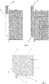
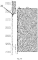
- Exemplary thermal-insulation and drying panel 1 is a shape composed of a cuboid inner layer 3 which, once installed on the insulated building, is in contact with the building wall, and a cuboid outer layer 2 which, once installed on the insulated building is to be covered with a finishing material.
- the outer 2 and inner 3 layers are offset to each other along both perpendicular edges and form an integral entity (the thermal-insulation and drying panel 1).
- the inner layer 3 which is not covered by the outer layer 2, cavities 14 for fastening elements are provided, in particular oval, round or oblong in shape.
- the thermal-insulation and drying panel 1 is designed to be fixed on the insulated wall in a horizontal position (with a longer edge of the panel 1 in a horizontal orientation).
- each slot 6 has an extension (an extended portion 7 of ventilation slots), and an upper portion of each slot 6 is a non-extended portion 9, whereby a contracting portion 8 is provided between them.
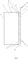
- oblong splines a horizontal spline 12 and a vertical spline 13
- keys a horizontal key 10 and a vertical key 11
- the horizontal key 10 is provided along the entire length of an upper edge of the outer layer 2, and the vertical key 11 is provided along a right edge of the outer layer 2 (when viewed from the outer layer 2 side of the thermal-insulation and drying panel 1).
- the horizontal spline 12 extends along a lower edge of the outer layer 2, with extended portions 7 of the ventilation slots 6 extending across the spline, thereby dividing the edge of the horizontal spline 12 into shorter sections, and the vertical spline 13 extends along a left edge of the outer layer 2 (when viewed from outer layer 2 side of the thermal-insulation and drying panel 1).
- All the splines 12, 13 and keys 10, 11 provided in the thermal-insulation and drying panel 1 have slightly convergent cross-section.
- the keys 10, 11 and the splines 12, 13 with trapezoid cross-section are provided, however it is clear that other cross-sections of the splines 12, 13 and the keys 10, 11 are possible.
- the main aim of modification of the cross-section is to facilitate the assembly of adjacent thermal-insulation and drying panels 1 together - even slightly convergent keys/splines facilitate sliding over and locking of one panel above the other.
- first positioning tongues 16 are provided, and on the lower edge of the outer layer 2 corresponding first positioning grooves 17 are provided.
- the first positioning tongues 16 and the corresponding first positioning grooves 17 are arranged at regular intervals, corresponding to the intervals between the ventilation slots 6.
- the first positioning tongues 16 and the first positioning grooves 17 are arranged essentially between the slots, at regular intervals from each side from the adjacent slots 6, but it is not the only possible and preferred configuration.
- first positioning tongues 16 and the first positioning grooves 17 are provided at regular intervals, but offset to the ventilation slots 6 or simply present directly in the same areas as the ventilation slots 6 (when viewed perpendicularly to the outer surface of the thermal-insulation and drying panel 1).
- first positioning tongues 16 and the first positioning grooves 17 each time have square cross-section and straight side walls, it is possible to use the first positioning tongues 16 and the first positioning grooves 17 having other shapes, e.g. oval, truncated pyramid, hemisphere, etc.
- first positioning tongues 16 and the first positioning grooves 17 having transverse dimensions greater than the width of cross section of the ventilation slots 6.
- the thermal-insulation and drying panels 1 of large thickness in particular with thicker outer layer 2, suitable for thermal insulation of buildings in a harsh climate, e.g. in northern Europe
- first positioning tongues 16 are located on the upper edge of the outer layer 2 and the first positioning grooves 17 are located on the lower edge of the outer layer 2, it is clear that they can be provided in a reverse configuration or even alternately - along the upper edge, tongue-groove-tongue-groove, etc., and along the lower edge - groove-tongue-groove, etc., respectively.
- the first positioning grooves 17 and the first positioning tongues 16 have corresponding shapes and are arranged in relation to each other in such a way that during the assembly of the thermal-insulation and drying panels 1 one above the other, they determined such mutual positioning of the panels 1 that the ventilation slots 6 of adjacent panels 1 were positioned facing each other maintaining the vertical continuity of the ventilation slots 6 and ensuring the free air flow along the ventilation slots 6.
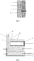
- This ventilation duct 15 has a cross-section with partially contracting sides, which after reaching a certain close-up start to extend in parallel to one another (the cross-section is therefore close to a trapezium with parallel bases, wherein to a shorter base edge a rectangle is joined having a shorter side being equal in length to the shorter base of the trapezium).
- the ventilation slots 6 provided in the inner layer 3 of the thermal-insulation and drying panel 1 penetrate the horizontal key 10 at least half of the height of the ventilation duct 15, defined by the ventilation duct 15 side walls extending parallel to each other, and preferably are contact the ventilation duct 15 along a section of at least or approximately 0.6 of the height of the ventilation duct 15.
- this contact area is much greater and thus the air flowing through the ventilation slots 6 to the ventilation duct 15 faces significantly lower flow resistance.
- vents 20 in addition to providing better airflow from one thermal-insulation and drying panel 1 to another, located above the first one, enables to arrange vents 20 in the thermal-insulation and drying panel 1.
- the vents 20 are essential due to the reduction of total length of vertical air ducts along the ventilation slots 6. In such situation vents 20 operate in pairs - the vent 20 provided in the lower area of air duct is an inlet (enables ambient air to enter the area between the thermal-insulation and drying panel 1 and the wall), while the vent 20 provided in the upper area of air duct is an outlet (enables the air to flow outside, thereby transporting the moisture away from the wall).
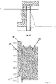
- vents 20 are placed in some of the thermal-insulation and drying panels 1 already after fixing the thermal-insulation and drying panels 1 to the wall, it is preferable to facilitate installation of these vents 20, in particular so that the vents 20 would allow the air to be effectively removed from underneath the thermal-insulation and drying panel 1. This is achieved by placing the vent 20 axis at the level of the horizontal ventilation duct 15 centre (and more precisely - the centre of the ventilation duct portion with parallel side walls) of a given thermal-insulation and drying panel 1 so that the vent 20 is connected to the horizontal ventilation duct 15 at right angle, which in turn may pose certain difficulty for untrained workers installing the system.
- a guidance in form of a line located on the front face of the outer layer of the thermal-insulation and drying panel 1, said front face, after installation being parallel to the building wall, whereby this line indicates half of the horizontal ventilation duct height. Arranging the vent at this line minimizes the risk of failure to fit the vent into the horizontal ventilation duct.
- vents 20 are arranged at right angle to the thermal-insulation and drying panel 1 , in other embodiments it might be preferred to arrange the vents 20 inclined downwards in the direction of the outer side of panel, e.g. at an angle of 2° - 8° in relation to the horizontal, e.g. at an angle of 3°, 4° or 5°. Such slight inclination of the vents 20 allows them to realise an additional function of gravitational drainage of condensate from the inside of the thermal-insulation and drying panel 1 to the environment.
- vents 20 are necessary of accordingly large geometric dimensions. It has been established that due to heat exchange processes (cooling of building) and moisture drainage (wall drying), the vent 20 should have outer opening of bore (opening net area) between 360 mm 2 and 1500 mm 2 . In case of vents 20 in form of tube sections, a diameter of such vent 20 may be e.g. 50 mm.
- the vent 20 outer opening is provided with an external grille/net 21 (preferably welded, glued or screwed to the vent 20) - in such case the opening bore is counted as a total area of mesh of such grille/net 21.
- the thermal-insulation and drying panel 1 according to the invention preferably is made of expanded material, in particular expanded polystyrene or possibly expanded polyurethane.
- thermal-insulation and drying panels 1 after arranging the thermal-insulation and drying panels 1 in the assembled position at the wall(s) it is preferred to additionally use two types of protective substances - sealing and anti-fungal.
- Sealing substances such as, e.g. foams, can be used, e.g. to fill voids between the panels 1 or fill in the gaps resulting from mechanical damage (accidental chipping off) of portions of the thermal-insulation and drying panels 1.
- Anti-fungal substances e.g. in form of sprayed aerosol, can be used after installation of the wall thermal-insulation and drying system, e.g.
- the wall thermal-insulation and drying system includes:
- the installation of the wall thermal-insulation and drying system comprises the following steps:
- corner elements 25 are also used by being arranged in such areas like wall corners, while in contact areas of the thermal-insulation and drying panels 1 with windows/doors, or for finishings in the building roof area, etc.
- truncated/prefabricated elements from solid expanded polystyrene are preferably used.
- Said corner elements 25 preferably are shaped as prisms of different bases - square, rectangular, trapezoid or triangular, or as a quarter round, whereby said elements can be solid/monolithic or can comprise hollow spaces (e.g. extending along the entire height of the corner element 25).
- the corner elements 25 have geometric dimensions adjusted to the thermal-insulation and drying panels 1 being used, i.e. width and thickness of the corner elements 25 is close to or preferably the same as thickness of the thermal-insulation and drying panels 1, and respectively height of the corner elements 25 is close to or preferably the same as the height of the thermal-insulation and drying panels 1.
- an optional and preferable step is to cover the vents 20 with the ventilation grilles 21 - unless the grilles 21 are pre-integrated (e.g. glued) with the vents 20.
- the grilles 21 are mounted on the vents 20 preferably by screwing threaded connections or using snap-fit connections. It is also important that, during possible further step of covering the outer surface of already assembled thermal-insulation and drying panels 1 (and corner elements 25 - if present) with a layer of finishing material, e.g. plaster, the vents 20/the ventilation grilles 21 remain unobstructed, and therefore airflow is not disabled.
- material(s) to be used for covering outer surfaces of already assembled thermal-insulation and drying panels should be selected in accordance with commonly used technologies of external plastering on expanded polystyrene substrates.
- Group of materials which are particularly preferable to be used includes: plaster, ceramic tiles, paint, mineral-based coating or plastic coating.
Landscapes
- Engineering & Computer Science (AREA)
- Architecture (AREA)
- Civil Engineering (AREA)
- Structural Engineering (AREA)
- Physics & Mathematics (AREA)
- Mechanical Engineering (AREA)
- Acoustics & Sound (AREA)
- Electromagnetism (AREA)
- Life Sciences & Earth Sciences (AREA)
- Wood Science & Technology (AREA)
- Building Environments (AREA)
Claims (15)
- Eine Wärmedämm- und Trocknungsplatte (1) mit einer Form, die aus zwei im wesentlichen quaderförmigen Schichten besteht: einer inneren Schicht (3) und einer äußeren Schicht (2), wobei die Schichten (2, 3) entlang zweier senkrechter Kanten zueinander versetzt sind und ein integrales Element bilden,wobei in einem Übergangsbereich der äußeren Schicht (2) in die innere Schicht (3) ein Verschiebebereich vorhanden ist,wobei eine erste Seite (4) der inneren Schicht (3) so gestaltet ist, dass sie mit einer gedämmten Wand im Kontakt ist, und die andere Seite (5) der äußeren Schicht (2), die nicht in Kontakt mit der inneren Schicht ist, in einem zusammengebauten Zustand so angeordnet ist, dass sie der Umgebung der gedämmten Wand zugewandt ist, und so gestaltet ist, dass sie mit einem Veredelungsmaterial bedeckt ist, wobei die Seiten der Platte (1), die nicht die erste Seite und die zweite Seite sind, Seitenwände der Platte (1) bilden,wobei in der inneren Schicht (3) an der ersten Seite (4), die für den Kontakt mit der gedämmten Wand gestaltet ist, Belüftungsschlitze (6) in regelmäßigen Abständen und parallel zueinander angeordnet sind, die sich senkrecht zu längeren Seiten der Platte (1) erstrecken,wobei untere Teile der Schlitze (6) erweitert sind, so dass entlang des Verlaufs der Belüftungsschlitze (6) innerhalb einer einzelnen Wärmedämm- und Trocknungsplatte (1) die Belüftungsschlitze (6), ausgehend von der Unterseite, einen erweiterten Teil (7) mit einer im Wesentlichen konstanten Breite, einen sich zusammenziehenden Teil (8) mit einer variablen Breite und einen nicht erweiterten Teil (9) mit einer im Wesentlichen konstanten Breite umfassen,wobei im Verschiebebereich zwischen der inneren Schicht (3) und der äußeren Schicht (2) längliche, sich entlang der Seitenwände der Wärmedämm- und Trocknungsplatte (1) erstreckende Nuten und Keile vorgesehen sind,wobei sich eine horizontale Nut (10) entlang einer oberen Kante der äußeren Schicht (2) erstreckt, während sich eine vertikale Nut (11) entlang einer rechten Kante der äußeren Schicht (2) erstreckt, wenn man sie von der Außenseite der Wärmedämm- und Trocknungsplatte (1) betrachtet,wobei sich ein horizontaler Keil (12) entlang einer unteren Kante der äußeren Schicht (2) erstreckt, so dass Erweiterungen von Belüftungsschlitzen (6) durch diese hindurchgehen, während sich ein vertikaler Keil (13) entlang einer linken Kante der äußeren Schicht (2) erstreckt, wenn man sie von der Außenseite der Wärmedämm- und Trocknungsplatte (1) betrachtet,wobei alle länglichen Nuten (10, 11) und Keile (12, 13) einen leicht konvergierenden Querschnitt aufweisen,wobei eine Tiefe des horizontalen Keils (10) in der Wärmedämm- und Trocknungsplatte (1) größer ist als eine Länge des horizontalen Keils (11),wobei an von der Außenschicht (2) nicht bedeckten Oberflächenabschnitten der Innenschicht (3) Hohlräume für Befestigungselemente (14) zur Befestigung der Wärmedämm- und Trockenplatte (1) an der gedämmten Wand vorgesehen sind,dadurch gekennzeichnet, dass die Unterseite der horizontalen Nut (10) zusätzlich in Richtung der Unterkante der Wärmedämm- und Trocknungsplatte (1) vertieft ist, wobei diese Vertiefung einen Lüftungskanal (15) bildet, der sich im Wesentlichen senkrecht zu den Belüftungsschlitzen (6) erstreckt, die den Lüftungskanal (15) mindestens in der halben Höhe des Lüftungskanals (15), gemessen von einem Boden des Kanals (15), berühren, und vorzugsweise den Lüftungskanal (15) mindestens in einem Abschnitt berühren, der das 0. 6-fachen der Höhe des Lüftungskanals (15).
- Die Wärmedämm- und Trocknungsplatte (1) nach Anspruch 1, dadurch gekennzeichnet, dass an der Oberseite der Platte (1) Positionierungselemente in Form von ersten Positionierungsvorsprungen (16) und/oder zweiten Positionierungsspalten (28) und an der Unterseite der Platte (1) entsprechende Positionierungselemente in Form von ersten Positionierungsvorsprungen (17) und/oder zweiten Positionierungsspalten (27) vorgesehen sind.
- Die Wärmedämm- und Trocknungsplatte (1) nach Anspruch 1 oder 2, dadurch gekennzeichnet, dass der obere Teil jedes mit dem Lüftungskanal (15) verbundenen Belüftungsschlitzes (6) bogenförmig ist, wobei der Bogenradius (26) vorzugsweise 35 mm beträgt.
- Die Wärmedämm- und Trocknungsplatte (1) nach einem der Ansprüche 1 bis 3, dadurch gekennzeichnet, dass die oberen Enden der Belüftungsschlitze (6) abgerundete Seitenkanten aufweisen, die Rundungen (18) bilden, wobei vorzugsweise die Rundungen (18) der Seitenkanten der oberen Enden der Lüftungsschlitze einen Radius von 5 mm bis 20 mm, vorzugsweise gleich 10 mm, aufweisen.
- Die Wärmedämm- und Trocknungsplatte (1) nach einem der Ansprüche 1 bis 4, dadurch gekennzeichnet, dass die Seite der Außenschicht (2), die dazu vogesehen ist, mit einem Veredelungsmaterial bedeckt zu werden, mit einer zusätzlichen Materialschicht bedeckt ist, die vorzugsweise aus einer Gruppe umfassend: Gips, Keramikfliesen, Farbe, Beschichtung auf Mineralbasis oder Kunststoffbeschichtung ausgewählt ist.
- Die Wärmedämm- und Trocknungsplatte (1) nach einem der Ansprüche 1 bis 5, dadurch gekennzeichnet, dass auf der äußersten Oberfläche der Wärmedämm- und Trocknungsplatte (1), die dazu vogesehen ist, mit einem Veredelungsmaterial bedeckt zu werden, eine Markierung (19) vorhanden ist, die sich parallel zum Lüftungskanal (15) erstreckt und die Hälfte der Höhe des Lüftungskanals (15) definiert.
- Die Wärmedämm- und Trocknungsplatte (1) nach einem der Ansprüche 1 bis 6, dadurch gekennzeichnet, dass die Belüftungsschlitze (6) in ihrem nicht erweiterten Teil eine Breite von 5 mm bis 10 mm, vorzugsweise gleich 7 mm, aufweisen und im erweiterten Teil 15 mm breit sind, wobei die Mittelpunkte benachbarter Belüftungsschlitze in einem Abstand von 35 mm bis 100 mm, vorzugsweise gleich 50 mm, angeordnet sind.
- Die Wärmedämm- und Trocknungsplatte (1) nach einem der Ansprüche 1-7, dadurch gekennzeichnet, dass die Gesamtdicke der Platte (1) zwischen 60 mm und 300 mm, insbesondere zwischen 120 mm und 300 mm, wie z.B. 120 mm, 180 mm oder 220 mm beträgt.
- Die Wärmedämm- und Trocknungsplatte (1) nach einem der Ansprüche 1-8, dadurch gekennzeichnet, dass sie aus einem leichten Material mit guten Wärmedämmeigenschaften, vorzugsweise aus geschäumtem Material, insbesondere aus geschäumtem Polystyrol oder Polyurethan, hergestellt ist.
- Ein System zur Wärmedämmung und Trocknung von Wänden, umfassend:Wärmedämm- und Trocknungsplatten (1) nach einem der Ansprüche 1-9,Befestigungsmittel, vorzugsweise die Wanddübeln und/oder ein Klebstoff zur Befestigung der Platten an einer Wand,Entlüftungsöffnungen (20), die in den Wärmedämm- und Trocknungsplatten (1) anzuordnen sind, wobei die Länge der Entlüftungsöffnungen (20) der Länge entspricht, die zwischen dem Lüftungskanal (15) und der Außenfläche der Wärmedämm- und Trocknungsplatte (1) gemessen wird, die dazu gestaltet ist, mit Veredelungsmaterial bedeckt zu werden,Lüftungsgitter (21), die zur Abdeckung der äußeren Öffnungen der Entlüftungsöffnungen (20) geeignet sind,eine Folie (22) zur Abtrennung einzelner vertikaler Luftkanäle, jeweils begrenzt durch die Entlüftungsöffnungen (20), die Belüftungsschlitze (6) und die Lüftungskanäle (15), wobei die Folie zur Anordnung zwischen dem horizontalen Keil (12) und der horizontalen Nut (10) vorgegebener und benachbarter Wärmedämm- und Trocknungsplatten (1) ausgebildet ist,Startrinnen (23), in die eine erste Reihe von Wärmedämm- und Trocknungsplatten (1) oder abgeschnittene Teile der Wärmedämm- und Trocknungsplatten (1), von unten beginnend, eingelegt werden,Startplatten (24), die in den Startrinnen (23) unter den Wärmedämm- und Trocknungsplatten (1) oder den abgeschnittenen Teilen der Wärmedämm- und Trocknungsplatten (1) angeordnet werden.
- Das System nach Anspruch 10, dadurch gekennzeichnet, dass es ferner umfasst:
Eckelemente (25) zum Anbringen an Ecken und/oder Seitenenden des Systems zur Wärmedämmung und Trocknung von Wänden, wobei die Eckelemente (25) einen quadratischen Querschnitt aufweisen, wobei eine Seitenbreite dieses quadratischen Querschnitts gleich der Gesamtdicke der Wärmedämm- und Trocknungsplatten (1) ist. - Ein Verfahren zur Installation eines Systems zur Wärmedämmung und Trocknung von Wänden, das die folgenden Schritte umfassend:a) Anbringen einer Startrinne (23) an einer Wand unter Verwendung von Befestigungsmitteln, vorzugsweise Wanddübeln und/oder Klebstoff zur Befestigung der Platten an der Wand;b) Einsetzen einer Startplatte (24) in die Startrinne (23),c) Auflegen der Wärmedämm- und Trocknungsplatte (1) oder des abgeschnittenen Teils der Wärmedämm- und Trocknungsplatte (1) auf die in die Startrinne (23) eingesetzte Startplatte (24),d) Befestigung der Wärmedämm- und Trocknungsplatten (1) oder der abgeschnittenen Teile der Wärmedämm- und Trocknungsplatten (1) an der Wand mit Hilfe von Befestigungsmitteln,e) Anordnen von Entlüftungsöffnungen (20) in den Wärmedämm- und Trocknungsplatten (1), so dass sie sich von der Außenfläche der Wärmedämm- und Trocknungsplatten (1) zu den horizontalen Lüftungskanälen (15) in den Wärmedämm- und Trocknungsplatten (1) erstrecken,wobei benachbarte horizontale Reihen der Wärmedämm- und Trocknungsplatten (1) mit einem horizontalen Versatz zueinander befestigt werden,wobei zwischen vorbestimmten horizontalen Reihen der Wärmedämm- und Trocknungsplatten (1) diehorizontale Nut (10) im oberen Teil der Wärmedämm- und Trocknungsplatte (1) mit der Folie (22) bedeckt ist, um vertikale Luftkanäle zu definieren, die vorzugsweise in regelmäßigen Abständen gleich der Höhe eines Geschosses angeordnet sind,dadurch gekennzeichnet, dass die Wärmedämm- und Trocknungsplatten (1) nach einem der Ansprüche 1-9 verwendet werden.
- Das Verfahren nach Anspruch 12, dadurch gekennzeichnet, dass die Kanten der an den Wänden befestigten Wärmedämm- und Trocknungsplatten (1) mit quaderförmigen Eckelementen (25) befestigt werden, die eine quadratische Grundfläche mit einer Seitenlänge gleich der Dicke der Wärmedämm- und Trocknungsplatten (1) aufweisen.
- Das Verfahren nach Anspruch 12 oder 13, dadurch gekennzeichnet, dass sich an den Schritt e) ein Schritt f) anschließt:
f) Abdeckung der Auslässe der Lüftungsöffnungen (20) mit Lüftungsgittern (21). - Das Verfahren nach einem der Ansprüche 12-14, dadurch gekennzeichnet, dass nach der Installation aller Wärmedämm- und Trocknungsplatten (1) deren äußere Oberfläche, die vogesehen ist, um mit Veredelungsmaterial bedeckt zu werden, mit Ausnahme der Lüftungsgitter (21) mit einer zusätzlichen Materialschicht bedeckt wird, die insbesondere aus einer Gruppeumfassend: die Gips, Kunststoff, Farbe und Keramikfliesen ausgewählt wird.
Priority Applications (2)
| Application Number | Priority Date | Filing Date | Title |
|---|---|---|---|
| PL19461612.4T PL3835504T3 (pl) | 2019-12-09 | 2019-12-09 | Płyta ocieplająco-osuszająca, system do izolacji cieplnej i osuszania ścian oraz sposób montażu systemu do izolacji cieplnej i osuszania ścian |
| EP19461612.4A EP3835504B1 (de) | 2019-12-09 | 2019-12-09 | Dämmungs- und trocknungsplatte, wärmedämmungs- und trocknungssystem für wände und montageverfahren für das wärmedämmungs- und trocknungssystem für wände |
Applications Claiming Priority (1)
| Application Number | Priority Date | Filing Date | Title |
|---|---|---|---|
| EP19461612.4A EP3835504B1 (de) | 2019-12-09 | 2019-12-09 | Dämmungs- und trocknungsplatte, wärmedämmungs- und trocknungssystem für wände und montageverfahren für das wärmedämmungs- und trocknungssystem für wände |
Publications (2)
| Publication Number | Publication Date |
|---|---|
| EP3835504A1 EP3835504A1 (de) | 2021-06-16 |
| EP3835504B1 true EP3835504B1 (de) | 2022-08-31 |
Family
ID=69167609
Family Applications (1)
| Application Number | Title | Priority Date | Filing Date |
|---|---|---|---|
| EP19461612.4A Active EP3835504B1 (de) | 2019-12-09 | 2019-12-09 | Dämmungs- und trocknungsplatte, wärmedämmungs- und trocknungssystem für wände und montageverfahren für das wärmedämmungs- und trocknungssystem für wände |
Country Status (2)
| Country | Link |
|---|---|
| EP (1) | EP3835504B1 (de) |
| PL (1) | PL3835504T3 (de) |
Families Citing this family (2)
| Publication number | Priority date | Publication date | Assignee | Title |
|---|---|---|---|---|
| CN113585647B (zh) * | 2021-08-23 | 2023-07-07 | 湖北欧宅新材料科技有限公司 | 一种易于拼装的竹木纤维集成墙板 |
| CN119571941B (zh) * | 2024-12-10 | 2026-02-13 | 中建二局第二建筑工程有限公司 | 一种基于嵌入式管道技术的装配式隔热外墙 |
Family Cites Families (3)
| Publication number | Priority date | Publication date | Assignee | Title |
|---|---|---|---|---|
| PL204238B1 (pl) | 2001-04-24 | 2009-12-31 | Izodom 2000 Polska Spo & Lstro | Budowlany moduł izolacyjny |
| EP2834427A1 (de) * | 2012-04-03 | 2015-02-11 | James Hardie Technology Limited | Integrierter faserzement und schaumstoff als isolierte verkleidung mit verstärkungen |
| US10480188B2 (en) * | 2017-03-13 | 2019-11-19 | Ross Power Investments Inc. | Insulation and ventilation systems for building structures |
-
2019
- 2019-12-09 PL PL19461612.4T patent/PL3835504T3/pl unknown
- 2019-12-09 EP EP19461612.4A patent/EP3835504B1/de active Active
Also Published As
| Publication number | Publication date |
|---|---|
| PL3835504T3 (pl) | 2022-12-05 |
| EP3835504A1 (de) | 2021-06-16 |
Similar Documents
| Publication | Publication Date | Title |
|---|---|---|
| US7367165B2 (en) | Moisture control strip | |
| KR100672867B1 (ko) | 통기용 퍼링 스트립 | |
| US4817506A (en) | Roof vent | |
| US20210115660A1 (en) | Soil gas barrier system, and ventilation panel for same | |
| US20130298497A1 (en) | Tile Kit and Method | |
| EP3835504B1 (de) | Dämmungs- und trocknungsplatte, wärmedämmungs- und trocknungssystem für wände und montageverfahren für das wärmedämmungs- und trocknungssystem für wände | |
| JPS60138141A (ja) | 屋根構造 | |
| US11913220B2 (en) | Thermal isolator | |
| US10472820B2 (en) | Exterior insulated finish wall assembly | |
| ITMI20000298A1 (it) | Pannello prefabbricato in calcestruzzo per l'edilizia industrializzata ad elevato isolamento termico e/o acustico | |
| US9151064B1 (en) | Construction device for releasing moisture from a building | |
| US20220018118A1 (en) | System and method for insulating an intermodal container | |
| US20130276385A1 (en) | Insulating system | |
| JP7075198B2 (ja) | 通気部材 | |
| EP2004924A1 (de) | Vorgegossene wandplatte | |
| WO2016043784A1 (en) | A construction device for releasing moisture from a building | |
| JP7162294B2 (ja) | 換気部材、換気部材の施工方法及び換気部材の製造方法 | |
| JP3081730B2 (ja) | 無落雪屋根の小屋裏の換気構造 | |
| ES2346616B1 (es) | Sistema de construccion con ladrillos y bloques aislantes termoacusticos perfeccionado. | |
| JP3031287U (ja) | 壁の通気止め | |
| JPH1183102A (ja) | 換気口ユニット | |
| ES2323209B1 (es) | Sistema para fachada ventilada simple. | |
| CA3059038C (en) | Soil gas barrier system, and ventilation panel for same | |
| JPH09328828A (ja) | 断熱気密パネルおよびそれを用いた断熱気密壁の施工方法 | |
| JP6958224B2 (ja) | 壁体通気構造 |
Legal Events
| Date | Code | Title | Description |
|---|---|---|---|
| PUAI | Public reference made under article 153(3) epc to a published international application that has entered the european phase |
Free format text: ORIGINAL CODE: 0009012 |
|
| STAA | Information on the status of an ep patent application or granted ep patent |
Free format text: STATUS: THE APPLICATION HAS BEEN PUBLISHED |
|
| AK | Designated contracting states |
Kind code of ref document: A1 Designated state(s): AL AT BE BG CH CY CZ DE DK EE ES FI FR GB GR HR HU IE IS IT LI LT LU LV MC MK MT NL NO PL PT RO RS SE SI SK SM TR |
|
| STAA | Information on the status of an ep patent application or granted ep patent |
Free format text: STATUS: REQUEST FOR EXAMINATION WAS MADE |
|
| 17P | Request for examination filed |
Effective date: 20211207 |
|
| RBV | Designated contracting states (corrected) |
Designated state(s): AL AT BE BG CH CY CZ DE DK EE ES FI FR GB GR HR HU IE IS IT LI LT LU LV MC MK MT NL NO PL PT RO RS SE SI SK SM TR |
|
| GRAP | Despatch of communication of intention to grant a patent |
Free format text: ORIGINAL CODE: EPIDOSNIGR1 |
|
| STAA | Information on the status of an ep patent application or granted ep patent |
Free format text: STATUS: GRANT OF PATENT IS INTENDED |
|
| RIC1 | Information provided on ipc code assigned before grant |
Ipc: E04C 2/20 20060101ALI20220318BHEP Ipc: E04F 13/00 20060101ALI20220318BHEP Ipc: E04C 2/52 20060101ALI20220318BHEP Ipc: E04B 1/76 20060101AFI20220318BHEP |
|
| INTG | Intention to grant announced |
Effective date: 20220421 |
|
| GRAJ | Information related to disapproval of communication of intention to grant by the applicant or resumption of examination proceedings by the epo deleted |
Free format text: ORIGINAL CODE: EPIDOSDIGR1 |
|
| STAA | Information on the status of an ep patent application or granted ep patent |
Free format text: STATUS: REQUEST FOR EXAMINATION WAS MADE |
|
| GRAS | Grant fee paid |
Free format text: ORIGINAL CODE: EPIDOSNIGR3 |
|
| STAA | Information on the status of an ep patent application or granted ep patent |
Free format text: STATUS: GRANT OF PATENT IS INTENDED |
|
| GRAP | Despatch of communication of intention to grant a patent |
Free format text: ORIGINAL CODE: EPIDOSNIGR1 |
|
| INTC | Intention to grant announced (deleted) | ||
| GRAA | (expected) grant |
Free format text: ORIGINAL CODE: 0009210 |
|
| STAA | Information on the status of an ep patent application or granted ep patent |
Free format text: STATUS: THE PATENT HAS BEEN GRANTED |
|
| INTG | Intention to grant announced |
Effective date: 20220720 |
|
| AK | Designated contracting states |
Kind code of ref document: B1 Designated state(s): AL AT BE BG CH CY CZ DE DK EE ES FI FR GB GR HR HU IE IS IT LI LT LU LV MC MK MT NL NO PL PT RO RS SE SI SK SM TR |
|
| REG | Reference to a national code |
Ref country code: CH Ref legal event code: EP Ref country code: GB Ref legal event code: FG4D |
|
| REG | Reference to a national code |
Ref country code: AT Ref legal event code: REF Ref document number: 1515381 Country of ref document: AT Kind code of ref document: T Effective date: 20220915 |
|
| REG | Reference to a national code |
Ref country code: DE Ref legal event code: R096 Ref document number: 602019018934 Country of ref document: DE |
|
| REG | Reference to a national code |
Ref country code: IE Ref legal event code: FG4D |
|
| REG | Reference to a national code |
Ref country code: NL Ref legal event code: FP |
|
| REG | Reference to a national code |
Ref country code: LT Ref legal event code: MG9D |
|
| PG25 | Lapsed in a contracting state [announced via postgrant information from national office to epo] |
Ref country code: SE Free format text: LAPSE BECAUSE OF FAILURE TO SUBMIT A TRANSLATION OF THE DESCRIPTION OR TO PAY THE FEE WITHIN THE PRESCRIBED TIME-LIMIT Effective date: 20220831 Ref country code: RS Free format text: LAPSE BECAUSE OF FAILURE TO SUBMIT A TRANSLATION OF THE DESCRIPTION OR TO PAY THE FEE WITHIN THE PRESCRIBED TIME-LIMIT Effective date: 20220831 Ref country code: NO Free format text: LAPSE BECAUSE OF FAILURE TO SUBMIT A TRANSLATION OF THE DESCRIPTION OR TO PAY THE FEE WITHIN THE PRESCRIBED TIME-LIMIT Effective date: 20221130 Ref country code: LV Free format text: LAPSE BECAUSE OF FAILURE TO SUBMIT A TRANSLATION OF THE DESCRIPTION OR TO PAY THE FEE WITHIN THE PRESCRIBED TIME-LIMIT Effective date: 20220831 Ref country code: LT Free format text: LAPSE BECAUSE OF FAILURE TO SUBMIT A TRANSLATION OF THE DESCRIPTION OR TO PAY THE FEE WITHIN THE PRESCRIBED TIME-LIMIT Effective date: 20220831 Ref country code: FI Free format text: LAPSE BECAUSE OF FAILURE TO SUBMIT A TRANSLATION OF THE DESCRIPTION OR TO PAY THE FEE WITHIN THE PRESCRIBED TIME-LIMIT Effective date: 20220831 |
|
| REG | Reference to a national code |
Ref country code: AT Ref legal event code: MK05 Ref document number: 1515381 Country of ref document: AT Kind code of ref document: T Effective date: 20220831 |
|
| PG25 | Lapsed in a contracting state [announced via postgrant information from national office to epo] |
Ref country code: IS Free format text: LAPSE BECAUSE OF FAILURE TO SUBMIT A TRANSLATION OF THE DESCRIPTION OR TO PAY THE FEE WITHIN THE PRESCRIBED TIME-LIMIT Effective date: 20221231 Ref country code: HR Free format text: LAPSE BECAUSE OF FAILURE TO SUBMIT A TRANSLATION OF THE DESCRIPTION OR TO PAY THE FEE WITHIN THE PRESCRIBED TIME-LIMIT Effective date: 20220831 Ref country code: GR Free format text: LAPSE BECAUSE OF FAILURE TO SUBMIT A TRANSLATION OF THE DESCRIPTION OR TO PAY THE FEE WITHIN THE PRESCRIBED TIME-LIMIT Effective date: 20221201 |
|
| PG25 | Lapsed in a contracting state [announced via postgrant information from national office to epo] |
Ref country code: SM Free format text: LAPSE BECAUSE OF FAILURE TO SUBMIT A TRANSLATION OF THE DESCRIPTION OR TO PAY THE FEE WITHIN THE PRESCRIBED TIME-LIMIT Effective date: 20220831 Ref country code: RO Free format text: LAPSE BECAUSE OF FAILURE TO SUBMIT A TRANSLATION OF THE DESCRIPTION OR TO PAY THE FEE WITHIN THE PRESCRIBED TIME-LIMIT Effective date: 20220831 Ref country code: PT Free format text: LAPSE BECAUSE OF FAILURE TO SUBMIT A TRANSLATION OF THE DESCRIPTION OR TO PAY THE FEE WITHIN THE PRESCRIBED TIME-LIMIT Effective date: 20230102 Ref country code: ES Free format text: LAPSE BECAUSE OF FAILURE TO SUBMIT A TRANSLATION OF THE DESCRIPTION OR TO PAY THE FEE WITHIN THE PRESCRIBED TIME-LIMIT Effective date: 20220831 Ref country code: DK Free format text: LAPSE BECAUSE OF FAILURE TO SUBMIT A TRANSLATION OF THE DESCRIPTION OR TO PAY THE FEE WITHIN THE PRESCRIBED TIME-LIMIT Effective date: 20220831 Ref country code: CZ Free format text: LAPSE BECAUSE OF FAILURE TO SUBMIT A TRANSLATION OF THE DESCRIPTION OR TO PAY THE FEE WITHIN THE PRESCRIBED TIME-LIMIT Effective date: 20220831 Ref country code: AT Free format text: LAPSE BECAUSE OF FAILURE TO SUBMIT A TRANSLATION OF THE DESCRIPTION OR TO PAY THE FEE WITHIN THE PRESCRIBED TIME-LIMIT Effective date: 20220831 |
|
| PG25 | Lapsed in a contracting state [announced via postgrant information from national office to epo] |
Ref country code: SK Free format text: LAPSE BECAUSE OF FAILURE TO SUBMIT A TRANSLATION OF THE DESCRIPTION OR TO PAY THE FEE WITHIN THE PRESCRIBED TIME-LIMIT Effective date: 20220831 Ref country code: EE Free format text: LAPSE BECAUSE OF FAILURE TO SUBMIT A TRANSLATION OF THE DESCRIPTION OR TO PAY THE FEE WITHIN THE PRESCRIBED TIME-LIMIT Effective date: 20220831 |
|
| REG | Reference to a national code |
Ref country code: DE Ref legal event code: R097 Ref document number: 602019018934 Country of ref document: DE |
|
| PG25 | Lapsed in a contracting state [announced via postgrant information from national office to epo] |
Ref country code: AL Free format text: LAPSE BECAUSE OF FAILURE TO SUBMIT A TRANSLATION OF THE DESCRIPTION OR TO PAY THE FEE WITHIN THE PRESCRIBED TIME-LIMIT Effective date: 20220831 |
|
| PLBE | No opposition filed within time limit |
Free format text: ORIGINAL CODE: 0009261 |
|
| STAA | Information on the status of an ep patent application or granted ep patent |
Free format text: STATUS: NO OPPOSITION FILED WITHIN TIME LIMIT |
|
| REG | Reference to a national code |
Ref country code: CH Ref legal event code: PL |
|
| 26N | No opposition filed |
Effective date: 20230601 |
|
| PG25 | Lapsed in a contracting state [announced via postgrant information from national office to epo] |
Ref country code: SI Free format text: LAPSE BECAUSE OF FAILURE TO SUBMIT A TRANSLATION OF THE DESCRIPTION OR TO PAY THE FEE WITHIN THE PRESCRIBED TIME-LIMIT Effective date: 20220831 Ref country code: LU Free format text: LAPSE BECAUSE OF NON-PAYMENT OF DUE FEES Effective date: 20221209 |
|
| PG25 | Lapsed in a contracting state [announced via postgrant information from national office to epo] |
Ref country code: LI Free format text: LAPSE BECAUSE OF NON-PAYMENT OF DUE FEES Effective date: 20221231 Ref country code: CH Free format text: LAPSE BECAUSE OF NON-PAYMENT OF DUE FEES Effective date: 20221231 |
|
| PG25 | Lapsed in a contracting state [announced via postgrant information from national office to epo] |
Ref country code: CY Free format text: LAPSE BECAUSE OF FAILURE TO SUBMIT A TRANSLATION OF THE DESCRIPTION OR TO PAY THE FEE WITHIN THE PRESCRIBED TIME-LIMIT Effective date: 20220831 |
|
| PG25 | Lapsed in a contracting state [announced via postgrant information from national office to epo] |
Ref country code: MK Free format text: LAPSE BECAUSE OF FAILURE TO SUBMIT A TRANSLATION OF THE DESCRIPTION OR TO PAY THE FEE WITHIN THE PRESCRIBED TIME-LIMIT Effective date: 20220831 Ref country code: HU Free format text: LAPSE BECAUSE OF FAILURE TO SUBMIT A TRANSLATION OF THE DESCRIPTION OR TO PAY THE FEE WITHIN THE PRESCRIBED TIME-LIMIT; INVALID AB INITIO Effective date: 20191209 |
|
| PG25 | Lapsed in a contracting state [announced via postgrant information from national office to epo] |
Ref country code: MC Free format text: LAPSE BECAUSE OF FAILURE TO SUBMIT A TRANSLATION OF THE DESCRIPTION OR TO PAY THE FEE WITHIN THE PRESCRIBED TIME-LIMIT Effective date: 20220831 |
|
| PG25 | Lapsed in a contracting state [announced via postgrant information from national office to epo] |
Ref country code: MC Free format text: LAPSE BECAUSE OF FAILURE TO SUBMIT A TRANSLATION OF THE DESCRIPTION OR TO PAY THE FEE WITHIN THE PRESCRIBED TIME-LIMIT Effective date: 20220831 |
|
| PG25 | Lapsed in a contracting state [announced via postgrant information from national office to epo] |
Ref country code: BG Free format text: LAPSE BECAUSE OF FAILURE TO SUBMIT A TRANSLATION OF THE DESCRIPTION OR TO PAY THE FEE WITHIN THE PRESCRIBED TIME-LIMIT Effective date: 20220831 |
|
| GBPC | Gb: european patent ceased through non-payment of renewal fee |
Effective date: 20231209 |
|
| PG25 | Lapsed in a contracting state [announced via postgrant information from national office to epo] |
Ref country code: MT Free format text: LAPSE BECAUSE OF FAILURE TO SUBMIT A TRANSLATION OF THE DESCRIPTION OR TO PAY THE FEE WITHIN THE PRESCRIBED TIME-LIMIT Effective date: 20220831 |
|
| PG25 | Lapsed in a contracting state [announced via postgrant information from national office to epo] |
Ref country code: GB Free format text: LAPSE BECAUSE OF NON-PAYMENT OF DUE FEES Effective date: 20231209 |
|
| PG25 | Lapsed in a contracting state [announced via postgrant information from national office to epo] |
Ref country code: GB Free format text: LAPSE BECAUSE OF NON-PAYMENT OF DUE FEES Effective date: 20231209 |
|
| PGFP | Annual fee paid to national office [announced via postgrant information from national office to epo] |
Ref country code: NL Payment date: 20241003 Year of fee payment: 6 |
|
| PGFP | Annual fee paid to national office [announced via postgrant information from national office to epo] |
Ref country code: DE Payment date: 20241003 Year of fee payment: 6 |
|
| PGFP | Annual fee paid to national office [announced via postgrant information from national office to epo] |
Ref country code: BE Payment date: 20241003 Year of fee payment: 6 Ref country code: PL Payment date: 20241003 Year of fee payment: 6 |
|
| PGFP | Annual fee paid to national office [announced via postgrant information from national office to epo] |
Ref country code: FR Payment date: 20241003 Year of fee payment: 6 |
|
| PGFP | Annual fee paid to national office [announced via postgrant information from national office to epo] |
Ref country code: IE Payment date: 20241003 Year of fee payment: 6 |
|
| PGFP | Annual fee paid to national office [announced via postgrant information from national office to epo] |
Ref country code: IT Payment date: 20241203 Year of fee payment: 6 |
|
| PG25 | Lapsed in a contracting state [announced via postgrant information from national office to epo] |
Ref country code: TR Free format text: LAPSE BECAUSE OF FAILURE TO SUBMIT A TRANSLATION OF THE DESCRIPTION OR TO PAY THE FEE WITHIN THE PRESCRIBED TIME-LIMIT Effective date: 20220831 |