EP3835012B1 - Rasierkopf - Google Patents
Rasierkopf Download PDFInfo
- Publication number
- EP3835012B1 EP3835012B1 EP20213042.3A EP20213042A EP3835012B1 EP 3835012 B1 EP3835012 B1 EP 3835012B1 EP 20213042 A EP20213042 A EP 20213042A EP 3835012 B1 EP3835012 B1 EP 3835012B1
- Authority
- EP
- European Patent Office
- Prior art keywords
- mounting
- blade
- protrusions
- bases
- shaving
- Prior art date
- Legal status (The legal status is an assumption and is not a legal conclusion. Google has not performed a legal analysis and makes no representation as to the accuracy of the status listed.)
- Active
Links
Images


Classifications
-
- B—PERFORMING OPERATIONS; TRANSPORTING
- B26—HAND CUTTING TOOLS; CUTTING; SEVERING
- B26B—HAND-HELD CUTTING TOOLS NOT OTHERWISE PROVIDED FOR
- B26B21/00—Razors of the open or knife type; Safety razors or other shaving implements of the planing type; Hair-trimming devices involving a razor-blade; Equipment therefor
- B26B21/40—Details or accessories
- B26B21/4012—Housing details, e.g. for cartridges
- B26B21/4031—Housing details, e.g. for cartridges characterised by special geometric shaving parameters, e.g. blade span or exposure
-
- B—PERFORMING OPERATIONS; TRANSPORTING
- B26—HAND CUTTING TOOLS; CUTTING; SEVERING
- B26B—HAND-HELD CUTTING TOOLS NOT OTHERWISE PROVIDED FOR
- B26B21/00—Razors of the open or knife type; Safety razors or other shaving implements of the planing type; Hair-trimming devices involving a razor-blade; Equipment therefor
- B26B21/40—Details or accessories
- B26B21/4012—Housing details, e.g. for cartridges
-
- B—PERFORMING OPERATIONS; TRANSPORTING
- B26—HAND CUTTING TOOLS; CUTTING; SEVERING
- B26B—HAND-HELD CUTTING TOOLS NOT OTHERWISE PROVIDED FOR
- B26B21/00—Razors of the open or knife type; Safety razors or other shaving implements of the planing type; Hair-trimming devices involving a razor-blade; Equipment therefor
- B26B21/08—Razors of the open or knife type; Safety razors or other shaving implements of the planing type; Hair-trimming devices involving a razor-blade; Equipment therefor involving changeable blades
- B26B21/14—Safety razors with one or more blades arranged transversely to the handle
- B26B21/22—Safety razors with one or more blades arranged transversely to the handle involving several blades to be used simultaneously
- B26B21/222—Safety razors with one or more blades arranged transversely to the handle involving several blades to be used simultaneously with the blades moulded into, or attached to, a changeable unit
-
- B—PERFORMING OPERATIONS; TRANSPORTING
- B26—HAND CUTTING TOOLS; CUTTING; SEVERING
- B26B—HAND-HELD CUTTING TOOLS NOT OTHERWISE PROVIDED FOR
- B26B21/00—Razors of the open or knife type; Safety razors or other shaving implements of the planing type; Hair-trimming devices involving a razor-blade; Equipment therefor
- B26B21/08—Razors of the open or knife type; Safety razors or other shaving implements of the planing type; Hair-trimming devices involving a razor-blade; Equipment therefor involving changeable blades
- B26B21/14—Safety razors with one or more blades arranged transversely to the handle
- B26B21/22—Safety razors with one or more blades arranged transversely to the handle involving several blades to be used simultaneously
-
- B—PERFORMING OPERATIONS; TRANSPORTING
- B26—HAND CUTTING TOOLS; CUTTING; SEVERING
- B26B—HAND-HELD CUTTING TOOLS NOT OTHERWISE PROVIDED FOR
- B26B21/00—Razors of the open or knife type; Safety razors or other shaving implements of the planing type; Hair-trimming devices involving a razor-blade; Equipment therefor
- B26B21/40—Details or accessories
- B26B21/4012—Housing details, e.g. for cartridges
- B26B21/4018—Guard elements
-
- B—PERFORMING OPERATIONS; TRANSPORTING
- B26—HAND CUTTING TOOLS; CUTTING; SEVERING
- B26B—HAND-HELD CUTTING TOOLS NOT OTHERWISE PROVIDED FOR
- B26B21/00—Razors of the open or knife type; Safety razors or other shaving implements of the planing type; Hair-trimming devices involving a razor-blade; Equipment therefor
- B26B21/40—Details or accessories
- B26B21/4068—Mounting devices; Manufacture of razors or cartridges
Definitions
- the present disclosure relates to a razor cartridge.
- the multi-blade razor cartridge may have a plurality of shaving blades disposed in a blade housing.
- the shaving blade may be supported by a blade mounting of the blade housing.
- the blade mounting may include a mounting base and a mounting protrusion extending from the mounting base, and the plurality of shaving blades may be supported by multiples of the mounting protrusion.
- Such razor cartridges are, for example, known from EP 2823941 A1 and EP 3072647 A1 .
- US 2009/113716 A1 discloses a shaving blade assembly pre-form comprising a blade frame comprising transverse connecting strips and a plurality of blades welded to the blade frame that span the transverse connecting strips along a length of the frame.
- the multi-blade razor cartridge can achieve the effect of cutting body hair by a single stroke with a plurality of shaving blades. This allows the multi-blade razor cartridge to provide the user with a clean shaving by a small number of strokes.
- the multi-blade razor cartridge needs to arrange a plurality of shaving blades within the limited space of the blade housing, a space-efficient shaving blade arrangement is required. To this end, it is necessary to narrow the transverse interval between the mounting protrusions supporting the shaving blades.
- the present invention provides a razor cartridge according to claim 1, claim 6 and claim 7.
- At least one embodiment of the present disclosure seeks to provide a razor cartridge including a blade mounting that is easy to manufacture while reducing the transverse interval between mounting protrusions.
- alphanumeric code such as first, second, i), ii), (a), (b), etc., in numbering components are used solely for the purpose of differentiating one component from the other but not to imply or suggest the substances, the order or sequence of the components.
- a part includes or “comprises” a component, the part is meant to further include other components, not excluding thereof unless there is a particular description contrary thereto.
- FIG. 1 is a perspective view of a razor cartridge 10 according to at least one embodiment of the present disclosure.
- FIG. 1 only one shaving blade 110 is shown for the convenience of description.
- the razor cartridge 10 includes at least one shaving blade 110 and a blade housing 120.
- the blade housing 120 may receive at least one shaving blade 110 in the longitudinal direction.
- the longitudinal direction refers to a direction along which the blade housing 120 is elongated.
- the longitudinal direction is a direction parallel to the Y-axis.
- At least one shaving blade 110 received on one side of the blade housing 120 may be maintained by a plurality of clips (not shown).
- the blade housing 120 may include a cap 121 and a guard 123, and has a blade mounting 122.
- the cap 121 may be disposed at the rear of the shaving blade 110, specifically, to be disposed on the top side of the blade housing 120 facing the cutting edge 1142 in FIG. 2 .
- the front and rear of the shaving blade 110 are defined based on the shaving direction of the razor cartridge 10. Accordingly, in FIG. 1 , the front and rear of the shaving blade 110 are, respectively, in the positive X-axis direction and the negative X-axis direction with respect to the shaving blade 110.
- the guard 123 may be disposed in front of the shaving blade 110 on the upper surface of the blade housing 120.
- the guard 123 can stretch the skin in the shaving direction while shaving before the cutting of the body hair by the shaving blade 110.
- This can erect the user's body hair in a direction perpendicular to the user's skin surface, whereby the shaving blade 110 can cut the body hair more easily.
- the blade mounting 122 accommodates at least one or more shaving blades 110 in the longitudinal direction.
- the blade mounting 122 has multiple mounting bases 124A-124C (or collectively 124) from which a plurality of mounting protrusions 126A-126C (or collectively 126) is erected for supporting the at least one shaving blade 110.
- the blade mounting 122 will be detailed with reference to FIG. 3 .
- FIGS. 2A to 2C are side views of different types of the shaving blade 110 according to some embodiments of the present disclosure.
- the shaving blade 110 includes a base portion 112 and an edge portion 114.
- the base portion 112 may be an area on the shaving blade 110, which is supported by a plurality of mounting protrusions 126.
- the edge portion 114 extends from the base portion 112 and may have a cutting edge 1142 at one end thereof.
- the shaving blades 110 according to some embodiments of the present disclosure may be classified into various types of blades, depending on the shape and manufacturing method thereof.
- FIGS. 2A to 2C to be described below illustrate various types of shaving blades 110 according to some embodiment of the present disclosure.
- the first shaving blade 110A may be an integral blade in which the base portion 112A and the edge portion 114A are integrally formed, a cutting edge 1142A formed at one end of the edge portion 114A.
- the base portion 112A of the first shaving blade 110A may include a bent region 116A.
- the second shaving blade 110B is a welded blade of which the edge portion 114B is fixed by being welded on one side of the base portion 112B.
- a cutting edge 1142B is formed at one end of the edge portion 114B.
- the base portion 112B of the second shaving blade 110B may include a bent region 116B, similar to the first shaving blade 110A.
- the base portion 112C and the edge portion 114C may be formed into an integral blade.
- a cutting edge 1142C is formed at one end of the edge portion 114C.
- the base portion 112C of the third shaving blade 110C may not include a bent region, unlike the first shaving blade 110C and the second shaving blade 110B. Accordingly, the third shaving blade 110C may have a substantially straight shape.
- the shaving blades shown in FIGS. 2A to 2C are merely some of the various shaving blades according to the present disclosure.
- the shaving blade according to the present disclosure may have a configuration other than the shaving blades illustrated in FIGS. 2A to 2C .
- FIG. 3 is a front view of the razor cartridge 10 according to at least one embodiment of the present disclosure.
- FIG. 3 illustrates only one shaving blade 110 for convenience of explanation, omitting the edge portion 114 thereof.
- the blade mounting 122 includes the multiple mounting bases 124 and mounting protrusions 126.
- the multiple mounting bases 124 are disposed to be spaced apart from each other along the longitudinal direction, and the mounting protrusions 126 are formed to protrude from the multiple mounting bases 124.
- the blade mounting 122 is shown to include three mounting bases 124, but the present disclosure is not limited thereto.
- the blade mounting 122 may include two or four or more mounting bases 124.
- the mounting protrusions 126 protruding from each of the multiple mounting bases 124 are disposed in a transverse direction perpendicular to the longitudinal direction.
- the transverse direction refers to a direction in which the blade housing 120 extends over a shorter span.
- the transverse direction is a direction parallel to the X-axis.
- each mounting base 124 is aligned along the transverse direction.
- each mounting base 124 is shown to be disposed collinearly along the transverse direction, but the present disclosure is not so limited.
- each mounting base 124 may be arranged in zigzags along the transverse direction, or they may be arranged out of alignment with each other.
- the transverse interval between the multiple mounting protrusions 126 is shown to be the same in all mounting bases 124, but the present disclosure is not limited thereto.
- the transverse interval between the multiple mounting protrusions 126 may be configured to be different for each mounting base 124 and/or for each mounting protrusion 126.
- FIG. 4 is a cross-sectional view of the razor cartridge 10 according to at least one embodiment of the present disclosure, taken in the direction IV-IV' of FIG. 1 .
- the base portion 112 of the shaving blade 110 is supported by the mounting protrusions 126 protruding from different mounting bases 124.
- Each shaving blade 110 is supported by each mounting protrusion 126 protruding from each mounting base 124.
- the shaving blade 110 is not supported by two or more mounting protrusions 126 from one mounting base 124, but it is supported by only one mounting protrusion 126 per mounting base 124.
- transverse interval W of the multiple mounting protrusions 126 disposed on each mounting base 124 is Z substantially wider than those between the conventional mounting protrusions. Specifically, transverse interval W between the multiple mounting protrusions 126 disposed on each mounting base 124 is equal to or greater than transverse spacing S of the cutting edges 1142 of the plurality of shaving blades 110.
- transverse interval W between the multiple mounting protrusions 126 disposed on each mounting base 124 may be equal to or greater than transverse width 'L' of the mounting protrusion 126.
- transverse interval W between the multiple mounting protrusions 126 refers to the shortest linear distance between one mounting protrusion 126 protruding from one mounting base 124 and the neighboring mounting protrusion 126 next to the one mounting protrusion 126.
- the blade mounting 122 allows transverse interval Wto be increased between the adjacent mounting protrusions 126 on one mounting base 124 by configuring the blade housing 120 to support a single shaving blade 110 with each mounting protrusion 126 protruding from each mounting base 124.
- the blade mounting 122 according to at least one embodiment of the present disclosure is advantageously easy to manufacture.
- transverse width 'L' of the mounting protrusion 126 may be 0.2 mm to 4.0 mm, preferably 0.38 mm to 1.28 mm.
- transverse interval W between the multiple mounting protrusions 126 may be 0.3 mm to 5.0 mm, preferably 0.62 mm to 1.52 mm.
- transverse interval S between the cutting edges 1142 may be 0.3 mm to 5.0 mm, preferably 0.5 mm to 1.4 mm.
- the present disclosure is not limited to these particular values or ranges.
- the base portion 112 of the shaving blade 110 may be supported by the mounting protrusions 126 by making point contact, linear contact, or surface contact therewith.
- the blade mounting 122 can somewhat widen the transverse interval between the mounting protrusions 126 such that the mounting protrusion 126 can be configured in various ways.
- the mounting protrusion 126 may have an advantageous shape for surface contact with the base portion 112 of the shaving blade 110.
- the base portion 112 may be supported more firmly by the mounting protrusions 126 by making surface contact with the mounting protrusions 126.
- the base portion 112 of the shaving blade 110 may be supported by at least three mounting protrusions 126 along the longitudinal direction.
- the base portion 112 may be supported by at least three mounting protrusions 126 each protruding from at least three mounting bases 124 spaced apart from each other along the longitudinal direction.
- any one of one surface and the other surface of the base portion 112 may be supported by at least one mounting protrusion 126, the other one of the one surface and the other surface of the base portion 112 may be supported by at least two mounting protrusions 126.
- one shaving blade 110 may be securely seated on the blade housing 120 by being supported by at least three mounting protrusions 126.
- the mounting protrusions 126 may be formed by injection molding on the mounting base 124, but the present disclosure is not limited thereto.
- the multiple mounting bases 124 may include a first mounting base 124A, a second mounting base 124B, and a third mounting base 124C.
- the blade mounting 122 may have multiple first mounting protrusions 126A arranged on the first mounting base 124A along the transverse direction.
- the second mounting base 124B may be spaced apart from the first mounting base 124A along the longitudinal direction in one direction.
- the blade mounting 122 may have multiple second mounting protrusions 126B arranged on the second mounting base 124B along the transverse direction.
- the third mounting base 124C may be spaced apart from the first mounting base 124A along the longitudinal direction in another direction.
- the blade mounting 122 may have multiple third mounting protrusions 126C arranged on the third mounting base 124C along the transverse direction.
- the multiple first mounting protrusions 126A may not be aligned with the multiple second mounting protrusions 126B and with the multiple third mounting protrusions 126C along the longitudinal direction.
- the multiple second mounting protrusions 126B may be aligned with the multiple third mounting protrusions 126C along the longitudinal direction.
- any one of the one surface and the other surface of the base portion 112 of the shaving blade 110 may be supported by the first mounting protrusion 126A, and the other one of the one surface and the other surface of the base portion 112 may be supported by the second mounting protrusion 126B and the third mounting protrusion 126C.
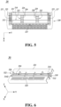
- FIG. 5 provides a blade housing that includes outer bases and outer protrusions.
- the following focuses on the distinctive features according to the second embodiment of the present disclosure, omitting a repetitive description of a configuration substantially the same as that of the aforementioned embodiments.
- FIG. 5 is a front view of a razor cartridge 20 according to the second embodiment of the present disclosure.
- FIG. 5 illustrates just one shaving blade 210, omitting an edge portion thereof for convenience of explanation.
- the blade housing 220 may include a cap 221, a guard 223, blade mountings 222, a plurality of outer bases 225, and a plurality of outer protrusions 227.
- the cap 221 may be disposed rearwardly of the shaving blade 210, and the guard 223 may be disposed in front of the shaving blade 210.
- the blade mountings 222 may receive at least one or more shaving blades 210 in the longitudinal direction.
- the blade mountings 222 may include multiple mounting bases 224 and multiple mounting protrusions 226.
- the multiple mounting bases 224 may be disposed to be spaced apart from each other in the longitudinal direction, and the multiple mounting protrusions 226 may protrude from each of the multiple mounting bases 224.
- the plurality of outer bases 225 may be disposed on both sides of the blade housing 220 along the longitudinal direction. Accordingly, the multiple blade mountings 222 may be disposed between the plurality of outer bases 225.
- the plurality of outer protrusions 227 may protrude from each outer base 225.
- the base portion 212 of the shaving blade 210 may be supported by the mounting protrusions 226 protruding from different mounting bases 224 and by at least two outer protrusions 227 protruding from one outer base 225.
- one of one surface and the other surface of the base portion 212 of the shaving blade 210 may be supported by one mounting protrusion 226 protruding from any one of the mounting bases 224, and the other one of the one surface and the other surface of the base portion 212 may be supported by one mounting protrusion 226 protruding from another mounting base 224.
- both surfaces of the base portion 212 of the shaving blade 210 may be supported by at least two outer protrusions 227 protruding from one outer base 225.
- the razor cartridge according to the second embodiment has the outer protrusions 227 disposed on both sides of the multiple mounting bases 224 and configured to support both surfaces of the base portion 212 of the shaving blade 210, and thereby keeps the shaving blade to be more firmly seated in the blade housing 220.
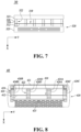
- FIGS. 6 and 7 provides outer bases and outer protrusions that are made of a plate.
- the following focuses on the distinctive features according to the third embodiment of the present disclosure, omitting a repetitive description of a configuration substantially the same as that of the aforementioned embodiments.
- FIG. 6 is a perspective view of a razor cartridge 30 according to the third embodiment of the present disclosure.
- FIG. 7 is a front view of a razor cartridge 30 according to the third embodiment of the present disclosure.
- FIGS. 6 and 7 illustrate just one shaving blade 310 with an edge portion 314 for convenience of description.
- FIG. 7 illustrates the shaving blade 310, omitting the edge portion 314 for convenience of explanation.
- the razor cartridge 30 may have a blade housing 320 that includes a cap 321, a guard 323, and a blade mounting 322.
- the cap 321 may be disposed rearwardly of the shaving blade 310, and the guard 323 may be disposed in front of the shaving blade 310.
- the blade mounting 322 may receive at least one shaving blade 310 in the longitudinal direction.
- the blade mounting 322 may include multiple mounting bases 324 and multiple mounting protrusions 326.
- the multiple mounting bases 324 may be disposed to be spaced apart from each other along the longitudinal direction, and the multiple mounting protrusions 326 may protrude from each of the multiple mounting bases 324.
- the base portion 312 may be supported by mounting protrusions 326 protruding from different mounting bases 324.
- a single shaving blade 310 may be supported by each mounting protrusion 326 protruding from each of the mounting bases 324.
- the base portion 312 of the single shaving blade 310 may be supported by a single mounting protrusion 326 protruding from a corresponding mounting base 324.
- the base portion 312 of the shaving blade 310 may be supported by at least three mounting protrusions 326 along the longitudinal direction. Specifically, the base portion 312 may be supported by at least three mounting protrusions 326 each protruding from at least three mounting bases 324 spaced apart from each other along the longitudinal direction.
- any one of one surface and the other surface of the base portion 312 may be supported by at least one mounting protrusion 326, the other one of the one surface and the other surface of the base portion 312 may be supported by at least two mounting protrusions 326.
- the mounting base 324 and the mounting protrusions 326 may be made of a single plate.
- the mounting protrusions 326 may be formed by being bent from the mounting base 324.
- the thickness of the plate may be 0.20 mm to 0.50 mm, and the mounting protrusions 326 may have the same thickness as the plate.
- the thickness of the mounting protrusions 326 is approximately eight times the thickness of the injection-molded mounting protrusion.
- the mounting protrusion 326 may have a thickness suitable for making surface contact with the base portion 312 of the shaving blade 310.
- the base portion 312 may be more firmly supported by the mounting protrusions 326 by making surface contact with the mounting protrusions 326.
- FIGS. 8 and 9 provide a blade mounting including four mounting bases.
- the following focuses on the distinctive features according to the fourth and fifth embodiments of the present disclosure, omitting a repetitive description of a configuration substantially the same as that of the aforementioned embodiments.
- FIG. 8 is a front view of a razor cartridge 40 according to the fourth embodiment of the present disclosure.
- FIG. 8 illustrates just one of a plurality of shaving blades 410, omitting an edge portion thereof for convenience of explanation.
- multiple mounting bases 424 may include a first mounting base 424A, a second mounting base 424B, a third mounting base 424C, and a fourth mounting base 424D.
- first mounting protrusions 426A may be disposed along the transverse direction.
- the second mounting base 424B may be spaced apart from the first mounting base 424A along the longitudinal direction in one direction. In the second mounting base 424B, multiple second mounting protrusions 426B may be disposed along the transverse direction.
- the third mounting base 424C may be spaced apart from the first mounting base 424A along the longitudinal direction in another direction opposite the one direction.
- multiple third mounting protrusions 426C may be disposed along the transverse direction.
- the fourth mounting base 424D may be disposed between the first mounting base 424A and the second mounting base 424B. Multiple fourth mounting protrusions 426D protruding from the fourth mounting base 424D may be disposed along the transverse direction.
- the multiple first mounting protrusions 426A may not be aligned with the multiple second mounting protrusions 426B and with the multiple third mounting protrusions 426C along the longitudinal direction.
- the multiple second mounting protrusions 426B may be aligned with the multiple third mounting protrusions 426C along the longitudinal direction, and the fourth mounting protrusion 426D may be arranged in parallel to the multiple first mounting protrusions 426A along the longitudinal direction.
- any one of one surface and the other surface of the base portion 412 of the shaving blade 410 may be supported by a first mounting protrusion 426A and a fourth mounting protrusion 426D, and the other of the one surface and the other surface of the base portion 412 may be supported by a second mounting protrusion 426B and a third mounting protrusion 426C.
- the base portion 412 to be supported by at least four mounting protrusions 426A-426D (or collectively 426), and the shaving blade 410 may be firmly seated on the blade housing 420.
- FIG. 9 is a front view of a razor cartridge 50 according to the fifth embodiment of the present disclosure.
- FIG. 9 illustrates just one of a plurality of shaving blades 510, omitting an edge portion thereof for convenience of explanation.
- multiple mounting bases 524 may include a first mounting base 524A, a second mounting base 524B, a third mounting base 524C, and a fifth mounting base 524E.
- first mounting protrusions 526A may be disposed along the transverse direction.
- the second mounting base 524B may be spaced apart from the first mounting base 524A along the longitudinal direction in one direction. In the second mounting base 524B, multiple second mounting protrusions 526B may be disposed along the transverse direction.
- the third mounting base 524C may be spaced apart from the first mounting base 524A along the longitudinal direction in another direction opposite the one direction.
- multiple third mounting protrusions 526C may be disposed along the transverse direction.
- multiple fifth mounting protrusions 526E may be disposed along the transverse direction, and the fifth mounting base 524E may be spaced apart from the second mounting base 524B along the longitudinal direction such that the second mounting base 524B is disposed between the first mounting base 524A and the fifth mounting base 524E.
- the multiple first mounting protrusions 526A and the multiple fifth mounting protrusions 526E may be arranged out of alignment with the multiple second mounting protrusions 526B and the multiple third mounting protrusions 526C along the longitudinal direction.
- the multiple second mounting protrusions 526B may be arranged in alignment with the multiple third mounting protrusions 526C along the longitudinal direction, and the multiple fifth mounting protrusions 526E may be arranged in alignment with the multiple first mounting protrusions 526A along the longitudinal direction.
- any one of one surface and the other surface of the base portion 512 of the shaving blade 510 may be supported by a first mounting protrusion 526A and a fifth mounting protrusion 526E, and the other of the one surface and the other surface of the base portion 512 may be supported by a second mounting protrusion 526B and a third mounting protrusion 526C.
- the base portion 512 may be supported by at least four mounting protrusions 526A, 526B, 526C, and 526E (or collectively 526), and the shaving blade 510 may be firmly seated on the blade housing 520.
- the following sixth embodiment of the present disclosure illustrated in FIG. 10 provides mounting bases each having multiple mounting protrusions with different transverse intervals for each of the mounting bases.
- the following focuses on the distinctive features according to the sixth embodiment, omitting a repetitive description of a configuration substantially the same as that of the aforementioned embodiments.
- FIG. 10 is a front view of a razor cartridge 60 according to the sixth embodiment of the present disclosure.
- FIG. 10 illustrates just two shaving blades 610A and 610B (or collectively 610) of a plurality of shaving blades for convenience of explanation. Therefore, the number of shaving blades 610 of the present disclosure is not limited to two, and an additional shaving blade may be further provided.
- FIG. 10 shows each shaving blade 610 having an edge portion for convenience of description.
- a blade housing 620 may be provided with a blade mounting 622 including multiple mounting bases 624 made of multiple sixth mounting bases 624F and multiple seventh mounting bases 624G.
- each of the sixth mounting bases 624F multiple sixth mounting protrusions 626F may be disposed along the transverse direction.
- the multiple seventh mounting bases 624G may be disposed to be spaced apart on both sides of the multiple sixth mounting bases 624F along the longitudinal direction.
- each of the seventh mounting bases 624G multiple seventh mounting protrusions 626G may be disposed along the transverse direction.
- the transverse interval between the multiple sixth mounting protrusions 626F may be a first distance D1
- the transverse interval between the multiple seventh mounting protrusions 626G may be a second distance D2 greater than first distance D1.
- the shaving blades 610 may have base portions 612A and 612B (or collectively 612) each having one surface facing the guard 623 and the other surface facing the cap 621.
- the base portion 612A of the front shaving blade 610A has one surface that is adjacent to the guard 623 and may be supported by two seventh mounting protrusions 626G protruding from different seventh mounting bases 624G, and the base portion 612A has the other surface supported by two sixth mounting protrusions 626F protruding from different sixth mounting bases 624F.
- the base portion 612B of the rear shaving blade 610B has one surface that is adjacent to the cap 621 and may be supported by two sixth mounting protrusions 626F protruding from the different sixth mounting bases 624F, and the base portion 612B has the other surface supported by two seventh mounting protrusions 626G protruding from the different seventh mounting bases 624G.
- the base portion 612A of the front shaving blade 610A and the base portion 612B of the rear shaving blade 610B may be supported by at least four mounting protrusions 626, respectively, and the front shaving blade 610A and the rear shaving blade 610B may be firmly seated on the blade housing 620.
- FIG. 10 illustrates that the blade mounting 622 is configured to have the multiple sixth mounting protrusions 626F with smaller transverse interval D1 therebetween and the multiple seventh mounting protrusions 626G with larger transverse interval D1 therebetween, the present disclosure is not limited thereto.
- the transverse interval between the multiple sixth mounting protrusions 626F may be larger than the transverse interval between the multiple seventh mounting protrusions 626G.
- one surface of the base portion 612A of the front shaving blade 610A may be supported by two sixth mounting protrusions 626F, and the other surface of the base portion 612A of the front shaving blade 610A may be supported by two protruding seventh mounting protrusions 626G.
- one surface of the base portion 612B of the rear shaving blade 610B may be supported by two seventh mounting protrusions 626G, and the other surface of the base portion 612B of the rear shaving blade 610B may be supported by two sixth mounting protrusions 626F.
Landscapes
- Life Sciences & Earth Sciences (AREA)
- Forests & Forestry (AREA)
- Engineering & Computer Science (AREA)
- Mechanical Engineering (AREA)
- Physics & Mathematics (AREA)
- Geometry (AREA)
- Packaging Of Annular Or Rod-Shaped Articles, Wearing Apparel, Cassettes, Or The Like (AREA)
Claims (13)
- Mehrfach-Wechselrasierklinge (10, 20, 30, 40, 50, 60), die umfasst:wenigstens eine Rasierklinge (110, 210, 310, 410, 510, 610), die jeweils einen Basisabschnitt (112, 212, 313, 412, 512, 612) sowie einen Kantenabschnitt (114, 314) mit einer Schneidkante (1142) enthält; undein Klingengehäuse (120, 220, 320, 420, 520, 620), das eine Klingenfassung (122, 222, 322, 422, 522, 622) enthält, die so ausgeführt ist, dass sie die wenigstens eine Rasierklinge (110, 210, 310, 410, 510, 610) in einer Längsrichtung aufnimmt, die einer Breitenrichtung des Klingengehäuses (120, 220, 320, 420, 520, 620) entspricht,wobeidie Klingenfassung (122, 222, 322, 422, 522, 622) enthält:mehrere Fassungs-Sockel (124, 224, 324, 424, 524, 624), die so angeordnet sind, dass sie in der Längsrichtung voneinander beabstandet sind; undwenigstens einen Fassungs-Vorsprung (126, 226, 326, 426, 526, 626), der von jedem der mehreren Fassungs-Sockel (124, 224, 324, 424, 524, 624) vorsteht, undwobei der Basisabschnitt (112, 212, 313, 412, 512, 612) einer Rasierklinge (110, 210, 310, 410, 510, 610) der wenigstens einen Rasierklinge (110, 210, 310, 410, 510, 610) über Fassungs-Vorsprünge (126, 226, 326, 426, 526, 626) gelagert ist, die von verschiedenen Fassungs-Sockeln (124, 224, 324, 424, 524, 624) der mehreren Fassungs-Sockel (124, 224, 324, 424, 524, 624) vorstehen,und der Basisabschnitt (112, 212, 313, 412, 512, 612) der Rasierklinge (110, 210, 310, 410, 510, 610) über einen einzelnen Fassungs-Vorsprung (126, 226, 326, 426, 526, 626) gelagert ist, der von jedem entsprechenden Fassungs-Sockel vorsteht.
- Mehrfach-Wechselrasierklinge (10, 30, 40, 50, 60) nach Anspruch 1, wobei der Basisabschnitt (112, 313, 412, 512, 612) der Rasierklinge (110, 310, 410, 510, 610) über wenigstens drei Fassungs-Vorsprünge (126, 326, 426, 526, 626) gelagert ist, wobei jeder der wenigstens drei Fassungs-Vorsprünge (126, 326, 426, 526, 626) von einem jeweils entsprechenden Fassungs-Sockel der mehreren Fassungs-Sockel (124, 324, 424, 524, 624) vorsteht, die mehreren Fassungs-Sockel (124, 324, 424, 524, 624) wenigstens drei Fassungs-Sockel (124, 324, 424, 524, 624) umfassen, die in der Längsrichtung voneinander beabstandet sind.
- Mehrfach-Wechselrasierklinge (10, 30, 40, 50, 60) nach Anspruch 1 oder 2, wobei der Basisabschnitt (112, 313, 412, 512, 612) der Rasierklinge (110, 310, 410, 510, 610) eine Fläche und eine gegenüberliegende Fläche aufweist, von denen eine über wenigstens einen oder mehr Fassungs-Vorsprünge (126, 326, 426, 526, 626) gelagert ist und von denen eine andere über wenigstens zwei oder mehr Fassungs-Vorsprünge (126, 326, 426, 526, 626) gelagert ist.
- Mehrfach-Wechselrasierklinge (10, 20, 30, 40, 50, 60) nach einem der Ansprüche 1 bis 3, wobei eine Vielzahl von Fassungs-Vorsprüngen (126, 226, 326, 426, 526, 626), die von jedem der mehreren Fassungs-Sockel (124, 224, 324, 424, 524, 624) vorstehen, in einer Querrichtung senkrecht zu der Längsrichtung angeordnet sind.
- Mehrfach-Wechselrasierklinge (10, 20, 30, 40, 50, 60) nach Anspruch 4, wobei die Fassungs-Vorsprünge (126, 226, 326, 426, 526, 626), die an jedem der mehreren Fassungs-Sockel (124, 224, 324, 424, 524, 624) angeordnet sind, in der Querrichtung ausgerichtet sind.
- Mehrfach-Wechselrasierklinge (10, 20, 30, 40, 50, 60), die umfasst:wenigstens eine Rasierklinge (110, 210, 310, 410, 510, 610), die jeweils einen Basisabschnitt (112, 212, 313, 412, 512, 612) sowie einen Kantenabschnitt (114, 314) mit einer Schneidkante (1142) enthält; undein Klingengehäuse (120, 220, 320, 420, 520, 620), das eine Klingenfassung (122, 222, 322, 422, 522, 622) enthält, die so ausgeführt ist, dass sie die wenigstens eine Rasierklinge (110, 210, 310, 410, 510, 610) in einer Längsrichtung aufnimmt, die einer Breitenrichtung des Klingengehäuses (120, 220, 320, 420, 520, 620) entspricht,wobei:die Klingenfassung (122, 222, 322, 422, 522, 622) enthält:mehrere Fassungs-Sockel (124, 224, 324, 424, 524, 624), die so angeordnet sind, dass sie in der Längsrichtung voneinander beabstandet sind; undwenigstens einen Fassungs-Vorsprung (126, 226, 326, 426, 526, 626), der von jedem der mehreren Fassungs-Sockel (124, 224, 324, 424, 524, 624) vorsteht, undwobei der Basisabschnitt (112, 212, 313, 412, 512, 612) einer Rasierklinge (110, 210, 310, 410, 510, 610) der wenigstens einen Rasierklinge (110, 210, 310, 410, 510, 610) über Fassungs-Vorsprünge (126, 226, 326, 426, 526, 626) gelagert ist, die von verschiedenen Fassungs-Sockeln (124, 224, 324, 424, 524, 624) der mehreren Fassungs-Sockel (124, 224, 324, 424, 524, 624) vorstehen,eine Vielzahl von Fassungs-Vorsprüngen (126, 226, 326, 426, 526, 626), die von jedem der mehreren Fassungs-Sockel (124, 224, 324, 424, 524, 624) vorstehen, in einer Querrichtung senkrecht zu der Längsrichtung angeordnet sind,die Fassungs-Vorsprünge (126, 226, 326, 426, 526, 626), die an jedem der mehreren Fassungs-Sockel (124, 224, 324, 424, 524, 624) angeordnet sind, in der Querrichtung ausgerichtet sind,
unddie Klingen-Fassung (122, 222, 322, 422, 522, 622) eine Vielzahl von Rasierklingen (110, 210, 310, 410, 510, 610) einschließlich der wenigstens einen Rasierklinge (110, 210, 310, 410, 510, 610) aufnimmt; unddie Fassungs-Vorsprünge (126, 226, 326, 426, 526, 626) an jedem der mehreren Fassungs-Sockel (124, 224, 324, 424, 524, 624) in Querabständen (W) angeordnet sind, die genauso groß sind wie oder größer als die Querabstände (S), in denen Schneidkanten (1142) der Rasierklingen (110, 210, 310, 410, 510, 610) angeordnet sind. - Mehrfach-Wechselrasierklinge (10, 20, 30, 40, 50, 60), die umfasst:wenigstens eine Rasierklinge (110, 210, 310, 410, 510, 610), die jeweils einen Basisabschnitt (112, 212, 313, 412, 512, 612) sowie einen Kantenabschnitt (114, 314) mit einer Schneidkante (1142) enthält; undein Klingengehäuse (120, 220, 320, 420, 520, 620), das eine Klingenfassung (122, 222, 322, 422, 522, 622) enthält, die so ausgeführt ist, dass sie die wenigstens eine Rasierklinge (110, 210, 310, 410, 510, 610) in einer Längsrichtung aufnimmt, die einer Breitenrichtung des Klingengehäuses (120, 220, 320, 420, 520, 620) entspricht,
unddie Klingenfassung (122, 222, 322, 422, 522, 622) enthält:mehrere Fassungs-Sockel (124, 224, 324, 424, 524, 624), die so angeordnet sind, dass sie in der Längsrichtung voneinander beabstandet sind; sowiewenigstens einen Fassungs-Vorsprung (126, 226, 326, 426, 526, 626), der von jedem der mehreren Fassungs-Sockel (124, 224, 324, 424, 524, 624) vorsteht, undder Basisabschnitt (112, 212, 313, 412, 512, 612) einer Rasierklinge (110, 210, 310, 410, 510, 610) der wenigstens einen Rasierklinge (110, 210, 310, 410, 510, 610) über Fassungs-Vorsprünge (126, 226, 326, 426, 526, 626) gelagert ist, die von verschiedenen Fassungs-Sockeln (124, 224, 324, 424, 524, 624) der mehreren Fassungs-Sockel (124, 224, 324, 424, 524, 624) vorstehen,eine Vielzahl von Fassungs-Vorsprüngen (126, 226, 326, 426, 526, 626), die von jedem der mehreren Fassungs-Sockel (124, 224, 324, 424, 524, 624) vorstehen, in einer Querrichtung senkrecht zu der Längsrichtung angeordnet sind,und die mehreren Fassungs-Sockel (124, 424, 524) umfassen:einen ersten Fassungs-Sockel (124A, 424A, 524A), der mehrere in der Querrichtung angeordnete erste Fassungs-Vorsprünge (126A, 426A, 526A) aufweist;einen zweiten Fassungs-Sockel (124B, 424B, 524B), der mehrere in der Querrichtung angeordnete zweite Fassungs-Vorsprünge (126B, 426B, 526B) aufweist und der von dem ersten Fassungs-Sockel (124A, 424A, 524A) in der Längsrichtung in einer Richtung beabstandet ist; undeinen dritten Fassungs-Sockel (124C, 424C, 524C), der mehrere in der Querrichtung angeordnete dritte Fassungs-Vorsprünge (126C, 426C, 526C) aufweist und der von dem ersten Fassungs-Sockel (124A, 424A, 524A) in der Längsrichtung in einer anderen Richtung beabstandet ist, die entgegengesetzt zu der einen Richtung ist;wobei die mehreren ersten Fassungs-Vorsprünge (126A, 426A, 526A) nicht mit den mehreren zweiten Fassungs-Vorsprüngen (126B, 426B, 526B) und den mehreren dritten Fassungs-Vorsprüngen (126C, 426C, 526C) in der Längsrichtung ausgerichtet sind, unddie mehreren zweiten Fassungs-Vorsprünge (126B, 426B, 526B) und die mehreren dritten Fassungs-Vorsprünge (126C, 426C, 526C) in der Längsrichtung ausgerichtet sind. - Mehrfach-Wechselrasierklinge (40) nach Anspruch 7, wobei die mehreren Fassungs-Sockel (424) des Weiteren umfassen:einen vierten Fassungs-Sockel (424D), der mehrere in der Querrichtung angeordnete vierte Fassungs-Vorsprünge (426D) aufweist und der zwischen dem ersten Fassungs-Sockel (424A) und dem zweiten Fassungs-Sockel (424B) angeordnet ist, undwobei die mehreren vierten Fassungs-Vorsprünge (426D) parallel zu den mehreren ersten Fassungs-Vorsprüngen (426A) in der Längsrichtung angeordnet sind.
- Mehrfach-Wechselrasierklinge (20) nach einem der Ansprüche 1 bis 8, wobei:das Klingengehäuse (220) des Weiteren eine Vielzahl äußerer Sockel (225), die an einer entsprechenden beider Seiten des Klingengehäuses (220) angeordnet sind, sowie eine Vielzahl äußerer Vorsprünge (227) enthält, die von jedem der äußeren Sockel (225) vorstehen; undder Basisabschnitt (212) der Rasierklinge (210) des Weiteren über wenigstens zwei äußere Vorsprünge (227) gelagert ist, die von einem der äußeren Sockel (225) vorstehen.
- Mehrfach-Wechselrasierklinge (20) nach Anspruch 9, wobei der Basisabschnitt (212) der Rasierklinge (210) eine Fläche und eine gegenüberliegende Fläche aufweist, die jeweils über wenigstens zwei äußere Vorsprünge (227) gelagert sind, die von einem der äußeren Sockel (225) vorstehen.
- Mehrfach-Wechselrasierklinge (10, 20, 30, 40, 50, 60) nach einem der Ansprüche 1 bis 10, wobei die Fassungs-Vorsprünge (126, 226, 326, 426, 526, 626) durch Biegen der Fassungs-Sockel (124, 224, 324, 424, 524, 624) ausgebildet werden.
- Mehrfach-Wechselrasierklinge (10, 20, 30, 40, 50, 60) nach Anspruch 11, wobei die Fassungs-Sockel (124, 224, 324, 524, 624) und die Fassungs-Vorsprünge (126, 226, 326, 426, 526, 626) aus einer Platte bestehen, und die Fassungs-Sockel (124, 224, 324, 424, 524, 624) sowie die Fassungs-Vorsprünge (126, 226, 326, 426, 526, 626) gleiche Dicke haben.
- Mehrfach-Wechselrasierklinge (10, 20, 30, 40, 50, 60) nach einem der Ansprüche 1 bis 10, wobei die Fassungs-Vorsprünge (126, 226, 326, 426, 526, 626) zusammen mit den Fassungs-Sockeln (124, 224, 324, 424, 524, 624) mittels Spritzgießen ausgebildet werden.
Applications Claiming Priority (1)
| Application Number | Priority Date | Filing Date | Title |
|---|---|---|---|
| KR1020190164111A KR102343058B1 (ko) | 2019-12-10 | 2019-12-10 | 면도기 카트리지 |
Publications (3)
| Publication Number | Publication Date |
|---|---|
| EP3835012A1 EP3835012A1 (de) | 2021-06-16 |
| EP3835012C0 EP3835012C0 (de) | 2023-10-11 |
| EP3835012B1 true EP3835012B1 (de) | 2023-10-11 |
Family
ID=73793038
Family Applications (1)
| Application Number | Title | Priority Date | Filing Date |
|---|---|---|---|
| EP20213042.3A Active EP3835012B1 (de) | 2019-12-10 | 2020-12-10 | Rasierkopf |
Country Status (3)
| Country | Link |
|---|---|
| US (1) | US12064888B2 (de) |
| EP (1) | EP3835012B1 (de) |
| KR (1) | KR102343058B1 (de) |
Families Citing this family (7)
| Publication number | Priority date | Publication date | Assignee | Title |
|---|---|---|---|---|
| US11345055B2 (en) * | 2018-09-05 | 2022-05-31 | The Gillette Company Llc | Razor cartridge structure |
| US12544944B2 (en) * | 2019-12-04 | 2026-02-10 | Mack-Ray Inc. | Dual sided razor |
| KR102343058B1 (ko) * | 2019-12-10 | 2021-12-24 | 주식회사 도루코 | 면도기 카트리지 |
| KR102496966B1 (ko) * | 2020-03-10 | 2023-02-07 | 주식회사 도루코 | 면도기 카트리지 |
| USD1014849S1 (en) * | 2021-04-05 | 2024-02-13 | Edgewell Personal Care Brands, Llc | Razor cartridge housing |
| KR102807693B1 (ko) * | 2021-11-30 | 2025-05-19 | 주식회사 도루코 | 면도기 카트리지 |
| USD1051499S1 (en) * | 2022-11-02 | 2024-11-12 | Ningbo Kaili Holding Group Co., Ltd. | Razor blade cartridge |
Citations (6)
| Publication number | Priority date | Publication date | Assignee | Title |
|---|---|---|---|---|
| WO2008002069A1 (en) | 2006-06-29 | 2008-01-03 | Dorco Co., Ltd | Shaver |
| US20090113716A1 (en) | 2007-11-02 | 2009-05-07 | Kevin James Wain | Razor Blade Assembly Pre-Form |
| US20090293281A1 (en) | 2008-05-30 | 2009-12-03 | Michael Hal Bruno | Blade support for multi-blade razor cartridges |
| EP2537648A1 (de) | 2011-06-20 | 2012-12-26 | The Gillette Company | Rasierklingenpatrone mit Hautkontaktelement |
| EP3072647A1 (de) | 2015-03-25 | 2016-09-28 | The Gillette Company | Rasierkopf |
| US20190299458A1 (en) | 2018-03-30 | 2019-10-03 | The Gillette Company Llc | Shaving razor cartridge and method of manufacture |
Family Cites Families (32)
| Publication number | Priority date | Publication date | Assignee | Title |
|---|---|---|---|---|
| BR9206813C1 (pt) | 1991-11-27 | 1999-12-28 | Gillette Co | Cartucho de aparelho de barbear de segurança substituìvel. |
| US6212777B1 (en) | 1993-09-29 | 2001-04-10 | The Gillette Company | Safety razors |
| CN1114521C (zh) | 1994-10-03 | 2003-07-16 | 吉莱特公司 | 剃刀组件 |
| US6516518B1 (en) | 1996-01-12 | 2003-02-11 | The Gillette Company | Razor blade unit |
| US6041926A (en) | 1996-04-10 | 2000-03-28 | The Gillette Company | Dispensing razor blade cartridges used with a handle |
| US5956851A (en) | 1996-04-10 | 1999-09-28 | The Gillette Company | Shaving system including handle and replaceable cartridges |
| US5687485A (en) | 1996-05-15 | 1997-11-18 | The Gillette Company | Razor handle |
| US5956848A (en) | 1997-02-27 | 1999-09-28 | The Gillette Company | Shaving system |
| US6684513B1 (en) | 2000-02-29 | 2004-02-03 | The Gillette Company | Razor blade technology |
| GB2408010B (en) * | 2003-11-17 | 2007-03-28 | Knowledge & Merchandising Inc | Shaving product |
| US10391652B2 (en) * | 2008-05-30 | 2019-08-27 | The Gillette Company Llc | Blade support for multi-blade razor cartirdges |
| JP5465869B2 (ja) | 2008-12-05 | 2014-04-09 | 株式会社貝印刃物開発センター | 替刃式剃刀 |
| RU2008150012A (ru) * | 2008-12-10 | 2010-06-20 | Александр Тарасович Володин (RU) | Лезвийный блок безопасной бритвы |
| KR20100091622A (ko) * | 2009-02-11 | 2010-08-19 | 주식회사 도루코 | 일체형 카트리지 |
| WO2013122900A1 (en) | 2012-02-13 | 2013-08-22 | Eveready Battery Company, Inc | Razor cartridge |
| US20140000114A1 (en) * | 2012-06-28 | 2014-01-02 | The Gillette Company | Shaving razor cartridge |
| EP2823941A1 (de) | 2013-07-10 | 2015-01-14 | The Gillette Company | Rasierklingenkartuschen |
| US10421204B2 (en) * | 2013-10-02 | 2019-09-24 | Dorco Co., Ltd. | Razor cartridges |
| JP6465893B2 (ja) * | 2013-12-18 | 2019-02-06 | ビック・バイオレクス・エス・エー | シェービング刃カートリッジ、そのようなシェービング刃カートリッジを製造するための方法、およびそのようなシェービング刃カートリッジを有する剃刀 |
| PL3072648T3 (pl) * | 2015-03-25 | 2017-12-29 | The Gillette Company Llc | Wkład maszynki do golenia |
| EP3072646B1 (de) * | 2015-03-25 | 2020-06-17 | The Gillette Company LLC | Rasierkopf |
| US10384360B2 (en) * | 2016-06-29 | 2019-08-20 | The Gillette Company Llc | Razor blade with a printed object |
| CN208246877U (zh) * | 2017-08-25 | 2018-12-18 | 宁波开利控股集团股份有限公司 | 一种矩阵式排列的漏须刀头 |
| KR101925281B1 (ko) * | 2017-11-29 | 2018-12-06 | 주식회사 도루코 | 면도기 카트리지 및 면도기 카트리지 어셈블리 |
| KR101876232B1 (ko) * | 2018-01-02 | 2018-07-10 | 주식회사 도루코 | 면도기 카트리지 |
| KR102081878B1 (ko) | 2018-05-21 | 2020-02-26 | 주식회사 도루코 | 면도기 카트리지 |
| EP3581350B1 (de) * | 2018-06-13 | 2022-07-27 | BIC Violex Single Member S.A. | Rasierapparat mit mehreren klingen |
| KR102106304B1 (ko) * | 2018-07-27 | 2020-05-04 | 주식회사 도루코 | 면도기 카트리지 |
| MX2021007698A (es) * | 2019-01-31 | 2021-09-21 | Bic Violex Sa | Cartucho de maquinilla de afeitar. |
| EP3771532B1 (de) * | 2019-07-31 | 2023-10-25 | BIC Violex Single Member S.A. | Rasierklingeneinsatz |
| KR102343058B1 (ko) * | 2019-12-10 | 2021-12-24 | 주식회사 도루코 | 면도기 카트리지 |
| EP3912774A1 (de) * | 2020-05-19 | 2021-11-24 | Société BIC | Rasierkopf mit magnetischem element |
-
2019
- 2019-12-10 KR KR1020190164111A patent/KR102343058B1/ko active Active
-
2020
- 2020-12-04 US US17/112,944 patent/US12064888B2/en active Active
- 2020-12-10 EP EP20213042.3A patent/EP3835012B1/de active Active
Patent Citations (7)
| Publication number | Priority date | Publication date | Assignee | Title |
|---|---|---|---|---|
| WO2008002069A1 (en) | 2006-06-29 | 2008-01-03 | Dorco Co., Ltd | Shaver |
| EP2032318A1 (de) | 2006-06-29 | 2009-03-11 | Dorco Co., Ltd | Rasierapparat |
| US20090113716A1 (en) | 2007-11-02 | 2009-05-07 | Kevin James Wain | Razor Blade Assembly Pre-Form |
| US20090293281A1 (en) | 2008-05-30 | 2009-12-03 | Michael Hal Bruno | Blade support for multi-blade razor cartridges |
| EP2537648A1 (de) | 2011-06-20 | 2012-12-26 | The Gillette Company | Rasierklingenpatrone mit Hautkontaktelement |
| EP3072647A1 (de) | 2015-03-25 | 2016-09-28 | The Gillette Company | Rasierkopf |
| US20190299458A1 (en) | 2018-03-30 | 2019-10-03 | The Gillette Company Llc | Shaving razor cartridge and method of manufacture |
Non-Patent Citations (26)
| Title |
|---|
| D10 - Bill of lading dated 29/11/2018 |
| D11 - Pictures |
| D12 - Technical drawings A18012003 Rev 1 |
| D13 - Technical drawings A18012002 Rev 1 |
| D14 - Affidavit of Mr Phaedon Papageorgis Papadopoulos |
| D15 - Sales data for the Flex 2 Hybrid cartridges in the US |
| D15a - Report summary for Flex 2 Hybrid Sales by Key Account exported on 02/19/2025 |
| D16 - Declaration of Miss Kristin Hornberger, 21.04.2025 |
| D17 - Engineering drawing labelled A18012003 Rev E, April 3, 2018 |
| D18 - Engineering drawing labelled A18012003 Rev 2, August 31, 2020 |
| D19 - Technical specifications document for the Flex 2 Hybrid razor version 2 and of October 1, 2019 |
| D20 - Technical specifications document for the Flex 2 Hybrid razor version 3 of September 13, 2024 |
| D21 - Comparison of selected views of D12, D17, and D18 |
| D22 - AMAZON: BIC® FLEX2™ HYBRID DISPOSABLE RAZOR, BLUE, 10 PACK |
| D23 - Affidavit of Mrs. Ourania Gavani |
| D23a - Tech Spec Montage (2 versions).pdf |
| D23b - Tech Spec of Packaging_1st version.pdf |
| D23c - Email from Ms D. Deswarte (BIC supply Chain Europe/MEA) 24-10-2018 |
| D23d - further evidence "ORACLE JD Edwards" |
| D24 - ISO 9001:2015 Clause 8.5.2 (Identification and Traceability) -NP |
| D25 - GS1 Global Traceability Standard (https://www.gs1.org/standards/gs1-global-traceability-standard/currentstandard#1-Introduction+1-1-Objective ) -NP |
| D26 - AMAZON WEBPAGE: DORCO SLEEK 6 BLADE RAZOR FOR MEN WITH 2 CARTRIDGES I MEN'S CARTRIDGE RAZORS WITH RAZOR HANDLE AND SMOOTH SHAVING BLADES I MEN'S RAZORS WITH MULTI-FLEX TECHNOLOGY |
| D27 - 3. AMAZON REVIEW THAT CAN BE EASILY ALTERED(PAGE ADDED) |
| D7 - Invoice dated 29/11/2018 |
| D8 - Item Spec Sheet for item Nr 7167844 |
| D9 - Item Spec Sheet for item Nr 7167845 |
Also Published As
| Publication number | Publication date |
|---|---|
| KR102343058B1 (ko) | 2021-12-24 |
| US20210170615A1 (en) | 2021-06-10 |
| EP3835012C0 (de) | 2023-10-11 |
| KR20210073350A (ko) | 2021-06-18 |
| US12064888B2 (en) | 2024-08-20 |
| EP3835012A1 (de) | 2021-06-16 |
Similar Documents
| Publication | Publication Date | Title |
|---|---|---|
| EP3835012B1 (de) | Rasierkopf | |
| US10981286B2 (en) | Razor system | |
| CN102046340B (zh) | 用于多刀片剃刀刀片架的刀片支撑体 | |
| US7191523B2 (en) | Safety razor | |
| EP2582497B1 (de) | Rasierkopf | |
| EP3492227B1 (de) | Rasierklingeneinheit | |
| CN104903059B (zh) | 狭缝式刀组件以及具有狭缝式刀组件的电动剃刀 | |
| US20140000114A1 (en) | Shaving razor cartridge | |
| KR102449754B1 (ko) | 면도기 시스템 | |
| AU2016235862A1 (en) | Shaving razor cartridge | |
| EP3072648B1 (de) | Rasierkopf | |
| KR20110134403A (ko) | 슬롯-밀링 공구 및 슬롯-밀링 공구용 슬롯-밀링 인서트 | |
| CN104870148A (zh) | 狭缝式刀组件和电动剃刀 | |
| KR100687842B1 (ko) | 왕복식 전기면도기용 내측 커터의 제조 방법 | |
| EP4319946B1 (de) | Rasierklingenkassette für nassrasierapparat mit klingenschlitzen | |
| KR102763342B1 (ko) | 교체 가능한 요소들을 갖는 블레이드 굴곡 조립체 | |
| CN220499204U (zh) | 一种可剃长胡须的多环往复式剃须刀 | |
| CN211022857U (zh) | 钉仓组件及使用该钉仓组件的腔内切割吻合器 | |
| KR102473133B1 (ko) | 면도기 카트리지 | |
| WO2018007130A1 (en) | Shaving cartridge |
Legal Events
| Date | Code | Title | Description |
|---|---|---|---|
| PUAI | Public reference made under article 153(3) epc to a published international application that has entered the european phase |
Free format text: ORIGINAL CODE: 0009012 |
|
| STAA | Information on the status of an ep patent application or granted ep patent |
Free format text: STATUS: THE APPLICATION HAS BEEN PUBLISHED |
|
| AK | Designated contracting states |
Kind code of ref document: A1 Designated state(s): AL AT BE BG CH CY CZ DE DK EE ES FI FR GB GR HR HU IE IS IT LI LT LU LV MC MK MT NL NO PL PT RO RS SE SI SK SM TR |
|
| STAA | Information on the status of an ep patent application or granted ep patent |
Free format text: STATUS: REQUEST FOR EXAMINATION WAS MADE |
|
| 17P | Request for examination filed |
Effective date: 20211216 |
|
| RBV | Designated contracting states (corrected) |
Designated state(s): AL AT BE BG CH CY CZ DE DK EE ES FI FR GB GR HR HU IE IS IT LI LT LU LV MC MK MT NL NO PL PT RO RS SE SI SK SM TR |
|
| GRAP | Despatch of communication of intention to grant a patent |
Free format text: ORIGINAL CODE: EPIDOSNIGR1 |
|
| STAA | Information on the status of an ep patent application or granted ep patent |
Free format text: STATUS: GRANT OF PATENT IS INTENDED |
|
| INTG | Intention to grant announced |
Effective date: 20230426 |
|
| GRAS | Grant fee paid |
Free format text: ORIGINAL CODE: EPIDOSNIGR3 |
|
| GRAA | (expected) grant |
Free format text: ORIGINAL CODE: 0009210 |
|
| STAA | Information on the status of an ep patent application or granted ep patent |
Free format text: STATUS: THE PATENT HAS BEEN GRANTED |
|
| AK | Designated contracting states |
Kind code of ref document: B1 Designated state(s): AL AT BE BG CH CY CZ DE DK EE ES FI FR GB GR HR HU IE IS IT LI LT LU LV MC MK MT NL NO PL PT RO RS SE SI SK SM TR |
|
| REG | Reference to a national code |
Ref country code: GB Ref legal event code: FG4D |
|
| REG | Reference to a national code |
Ref country code: CH Ref legal event code: EP |
|
| REG | Reference to a national code |
Ref country code: DE Ref legal event code: R096 Ref document number: 602020018993 Country of ref document: DE |
|
| REG | Reference to a national code |
Ref country code: IE Ref legal event code: FG4D |
|
| U01 | Request for unitary effect filed |
Effective date: 20231023 |
|
| U07 | Unitary effect registered |
Designated state(s): AT BE BG DE DK EE FI FR IT LT LU LV MT NL PT SE SI Effective date: 20231027 |
|
| U20 | Renewal fee for the european patent with unitary effect paid |
Year of fee payment: 4 Effective date: 20231129 |
|
| PG25 | Lapsed in a contracting state [announced via postgrant information from national office to epo] |
Ref country code: GR Free format text: LAPSE BECAUSE OF FAILURE TO SUBMIT A TRANSLATION OF THE DESCRIPTION OR TO PAY THE FEE WITHIN THE PRESCRIBED TIME-LIMIT Effective date: 20240112 |
|
| PG25 | Lapsed in a contracting state [announced via postgrant information from national office to epo] |
Ref country code: IS Free format text: LAPSE BECAUSE OF FAILURE TO SUBMIT A TRANSLATION OF THE DESCRIPTION OR TO PAY THE FEE WITHIN THE PRESCRIBED TIME-LIMIT Effective date: 20240211 |
|
| PG25 | Lapsed in a contracting state [announced via postgrant information from national office to epo] |
Ref country code: ES Free format text: LAPSE BECAUSE OF FAILURE TO SUBMIT A TRANSLATION OF THE DESCRIPTION OR TO PAY THE FEE WITHIN THE PRESCRIBED TIME-LIMIT Effective date: 20231011 |
|
| PG25 | Lapsed in a contracting state [announced via postgrant information from national office to epo] |
Ref country code: IS Free format text: LAPSE BECAUSE OF FAILURE TO SUBMIT A TRANSLATION OF THE DESCRIPTION OR TO PAY THE FEE WITHIN THE PRESCRIBED TIME-LIMIT Effective date: 20240211 Ref country code: GR Free format text: LAPSE BECAUSE OF FAILURE TO SUBMIT A TRANSLATION OF THE DESCRIPTION OR TO PAY THE FEE WITHIN THE PRESCRIBED TIME-LIMIT Effective date: 20240112 Ref country code: ES Free format text: LAPSE BECAUSE OF FAILURE TO SUBMIT A TRANSLATION OF THE DESCRIPTION OR TO PAY THE FEE WITHIN THE PRESCRIBED TIME-LIMIT Effective date: 20231011 |
|
| PG25 | Lapsed in a contracting state [announced via postgrant information from national office to epo] |
Ref country code: RS Free format text: LAPSE BECAUSE OF FAILURE TO SUBMIT A TRANSLATION OF THE DESCRIPTION OR TO PAY THE FEE WITHIN THE PRESCRIBED TIME-LIMIT Effective date: 20231011 Ref country code: PL Free format text: LAPSE BECAUSE OF FAILURE TO SUBMIT A TRANSLATION OF THE DESCRIPTION OR TO PAY THE FEE WITHIN THE PRESCRIBED TIME-LIMIT Effective date: 20231011 Ref country code: NO Free format text: LAPSE BECAUSE OF FAILURE TO SUBMIT A TRANSLATION OF THE DESCRIPTION OR TO PAY THE FEE WITHIN THE PRESCRIBED TIME-LIMIT Effective date: 20240111 Ref country code: HR Free format text: LAPSE BECAUSE OF FAILURE TO SUBMIT A TRANSLATION OF THE DESCRIPTION OR TO PAY THE FEE WITHIN THE PRESCRIBED TIME-LIMIT Effective date: 20231011 |
|
| REG | Reference to a national code |
Ref country code: DE Ref legal event code: R026 Ref document number: 602020018993 Country of ref document: DE |
|
| PLBI | Opposition filed |
Free format text: ORIGINAL CODE: 0009260 |
|
| PG25 | Lapsed in a contracting state [announced via postgrant information from national office to epo] |
Ref country code: CZ Free format text: LAPSE BECAUSE OF FAILURE TO SUBMIT A TRANSLATION OF THE DESCRIPTION OR TO PAY THE FEE WITHIN THE PRESCRIBED TIME-LIMIT Effective date: 20231011 |
|
| PG25 | Lapsed in a contracting state [announced via postgrant information from national office to epo] |
Ref country code: SK Free format text: LAPSE BECAUSE OF FAILURE TO SUBMIT A TRANSLATION OF THE DESCRIPTION OR TO PAY THE FEE WITHIN THE PRESCRIBED TIME-LIMIT Effective date: 20231011 |
|
| PG25 | Lapsed in a contracting state [announced via postgrant information from national office to epo] |
Ref country code: SM Free format text: LAPSE BECAUSE OF FAILURE TO SUBMIT A TRANSLATION OF THE DESCRIPTION OR TO PAY THE FEE WITHIN THE PRESCRIBED TIME-LIMIT Effective date: 20231011 Ref country code: SK Free format text: LAPSE BECAUSE OF FAILURE TO SUBMIT A TRANSLATION OF THE DESCRIPTION OR TO PAY THE FEE WITHIN THE PRESCRIBED TIME-LIMIT Effective date: 20231011 Ref country code: RO Free format text: LAPSE BECAUSE OF FAILURE TO SUBMIT A TRANSLATION OF THE DESCRIPTION OR TO PAY THE FEE WITHIN THE PRESCRIBED TIME-LIMIT Effective date: 20231011 Ref country code: CZ Free format text: LAPSE BECAUSE OF FAILURE TO SUBMIT A TRANSLATION OF THE DESCRIPTION OR TO PAY THE FEE WITHIN THE PRESCRIBED TIME-LIMIT Effective date: 20231011 |
|
| REG | Reference to a national code |
Ref country code: CH Ref legal event code: PL |
|
| 26 | Opposition filed |
Opponent name: BIC VIOLEX SINGLE MEMBER S.A. Effective date: 20240710 |
|
| PLAX | Notice of opposition and request to file observation + time limit sent |
Free format text: ORIGINAL CODE: EPIDOSNOBS2 |
|
| PG25 | Lapsed in a contracting state [announced via postgrant information from national office to epo] |
Ref country code: MC Free format text: LAPSE BECAUSE OF FAILURE TO SUBMIT A TRANSLATION OF THE DESCRIPTION OR TO PAY THE FEE WITHIN THE PRESCRIBED TIME-LIMIT Effective date: 20231011 |
|
| PG25 | Lapsed in a contracting state [announced via postgrant information from national office to epo] |
Ref country code: MC Free format text: LAPSE BECAUSE OF FAILURE TO SUBMIT A TRANSLATION OF THE DESCRIPTION OR TO PAY THE FEE WITHIN THE PRESCRIBED TIME-LIMIT Effective date: 20231011 |
|
| REG | Reference to a national code |
Ref country code: IE Ref legal event code: MM4A |
|
| PG25 | Lapsed in a contracting state [announced via postgrant information from national office to epo] |
Ref country code: IE Free format text: LAPSE BECAUSE OF NON-PAYMENT OF DUE FEES Effective date: 20231210 |
|
| PG25 | Lapsed in a contracting state [announced via postgrant information from national office to epo] |
Ref country code: CH Free format text: LAPSE BECAUSE OF NON-PAYMENT OF DUE FEES Effective date: 20231231 |
|
| PG25 | Lapsed in a contracting state [announced via postgrant information from national office to epo] |
Ref country code: IE Free format text: LAPSE BECAUSE OF NON-PAYMENT OF DUE FEES Effective date: 20231210 Ref country code: CH Free format text: LAPSE BECAUSE OF NON-PAYMENT OF DUE FEES Effective date: 20231231 |
|
| U20 | Renewal fee for the european patent with unitary effect paid |
Year of fee payment: 5 Effective date: 20241107 |
|
| PLBB | Reply of patent proprietor to notice(s) of opposition received |
Free format text: ORIGINAL CODE: EPIDOSNOBS3 |
|
| PG25 | Lapsed in a contracting state [announced via postgrant information from national office to epo] |
Ref country code: CY Free format text: LAPSE BECAUSE OF FAILURE TO SUBMIT A TRANSLATION OF THE DESCRIPTION OR TO PAY THE FEE WITHIN THE PRESCRIBED TIME-LIMIT; INVALID AB INITIO Effective date: 20201210 |
|
| PG25 | Lapsed in a contracting state [announced via postgrant information from national office to epo] |
Ref country code: HU Free format text: LAPSE BECAUSE OF FAILURE TO SUBMIT A TRANSLATION OF THE DESCRIPTION OR TO PAY THE FEE WITHIN THE PRESCRIBED TIME-LIMIT; INVALID AB INITIO Effective date: 20201210 |
|
| GBPC | Gb: european patent ceased through non-payment of renewal fee |
Effective date: 20241210 |
|
| PLAB | Opposition data, opponent's data or that of the opponent's representative modified |
Free format text: ORIGINAL CODE: 0009299OPPO |
|
| PLAY | Examination report in opposition despatched + time limit |
Free format text: ORIGINAL CODE: EPIDOSNORE2 |
|
| R26 | Opposition filed (corrected) |
Opponent name: BIC VIOLEX SINGLE MEMBER S.A. Effective date: 20240710 |
|
| PG25 | Lapsed in a contracting state [announced via postgrant information from national office to epo] |
Ref country code: GB Free format text: LAPSE BECAUSE OF NON-PAYMENT OF DUE FEES Effective date: 20241210 |
|
| PG25 | Lapsed in a contracting state [announced via postgrant information from national office to epo] |
Ref country code: TR Free format text: LAPSE BECAUSE OF FAILURE TO SUBMIT A TRANSLATION OF THE DESCRIPTION OR TO PAY THE FEE WITHIN THE PRESCRIBED TIME-LIMIT Effective date: 20231011 |
|
| PLBC | Reply to examination report in opposition received |
Free format text: ORIGINAL CODE: EPIDOSNORE3 |
|
| U1N | Appointed representative for the unitary patent procedure changed after the registration of the unitary effect |
Representative=s name: SONNENHAUSER, THOMAS MARTIN; DE |
|
| U20 | Renewal fee for the european patent with unitary effect paid |
Year of fee payment: 6 Effective date: 20251110 |