EP3834992B1 - Adapter und werkzeugmaschinensystem - Google Patents
Adapter und werkzeugmaschinensystem Download PDFInfo
- Publication number
- EP3834992B1 EP3834992B1 EP20213379.9A EP20213379A EP3834992B1 EP 3834992 B1 EP3834992 B1 EP 3834992B1 EP 20213379 A EP20213379 A EP 20213379A EP 3834992 B1 EP3834992 B1 EP 3834992B1
- Authority
- EP
- European Patent Office
- Prior art keywords
- terminal
- input
- voltage
- input terminal
- battery pack
- Prior art date
- Legal status (The legal status is an assumption and is not a legal conclusion. Google has not performed a legal analysis and makes no representation as to the accuracy of the status listed.)
- Active
Links
Images


Classifications
-
- H—ELECTRICITY
- H02—GENERATION; CONVERSION OR DISTRIBUTION OF ELECTRIC POWER
- H02J—ELECTRIC POWER NETWORKS; CIRCUIT ARRANGEMENTS OR SYSTEMS FOR SUPPLYING OR DISTRIBUTING ELECTRIC POWER; SYSTEMS FOR STORING ELECTRIC ENERGY
- H02J7/00—Circuit arrangements for charging or discharging batteries or for supplying loads from batteries
- H02J7/70—Circuit arrangements for charging or discharging batteries or for supplying loads from batteries characterised by the mechanical construction
- H02J7/731—Circuit arrangements for charging or discharging batteries or for supplying loads from batteries characterised by the mechanical construction specially adapted for holding portable devices containing batteries
-
- B—PERFORMING OPERATIONS; TRANSPORTING
- B25—HAND TOOLS; PORTABLE POWER-DRIVEN TOOLS; MANIPULATORS
- B25F—COMBINATION OR MULTI-PURPOSE TOOLS NOT OTHERWISE PROVIDED FOR; DETAILS OR COMPONENTS OF PORTABLE POWER-DRIVEN TOOLS NOT PARTICULARLY RELATED TO THE OPERATIONS PERFORMED AND NOT OTHERWISE PROVIDED FOR
- B25F1/00—Combination or multi-purpose hand tools
-
- B—PERFORMING OPERATIONS; TRANSPORTING
- B25—HAND TOOLS; PORTABLE POWER-DRIVEN TOOLS; MANIPULATORS
- B25F—COMBINATION OR MULTI-PURPOSE TOOLS NOT OTHERWISE PROVIDED FOR; DETAILS OR COMPONENTS OF PORTABLE POWER-DRIVEN TOOLS NOT PARTICULARLY RELATED TO THE OPERATIONS PERFORMED AND NOT OTHERWISE PROVIDED FOR
- B25F5/00—Details or components of portable power-driven tools not particularly related to the operations performed and not otherwise provided for
-
- H—ELECTRICITY
- H01—ELECTRIC ELEMENTS
- H01R—ELECTRICALLY-CONDUCTIVE CONNECTIONS; STRUCTURAL ASSOCIATIONS OF A PLURALITY OF MUTUALLY-INSULATED ELECTRICAL CONNECTING ELEMENTS; COUPLING DEVICES; CURRENT COLLECTORS
- H01R31/00—Coupling parts supported only by co-operation with counterpart
- H01R31/06—Intermediate parts for linking two coupling parts, e.g. adapter
-
- H—ELECTRICITY
- H02—GENERATION; CONVERSION OR DISTRIBUTION OF ELECTRIC POWER
- H02J—ELECTRIC POWER NETWORKS; CIRCUIT ARRANGEMENTS OR SYSTEMS FOR SUPPLYING OR DISTRIBUTING ELECTRIC POWER; SYSTEMS FOR STORING ELECTRIC ENERGY
- H02J7/00—Circuit arrangements for charging or discharging batteries or for supplying loads from batteries
- H02J7/855—Circuit arrangements for charging or discharging batteries or for supplying loads from batteries with circuits adapted for supplying loads from the battery
Definitions
- the invention relates to an adapter according to the preamble of claim 1 and a power tool system with the adapter according to the preamble of claim 15.
- a power tool system with the adapter according to the preamble of claim 15.
- Such an adapter and such a power tool system are known from US 2013/154584 A1 .
- the output interface disposed on the single-voltage battery pack is not coupleable with the input interface of the power tool mating with the multi-voltage battery pack, the output interface disposed on the multi-voltage battery pack is not coupleable with the input interface of the power tool mating with the single-voltage battery pack. So that the power tool mating with the single-voltage battery pack cannot mate with the multi-voltage battery pack. Furthermore, the power tool mating with the multi-voltage battery pack cannot match with the single-voltage battery pack.
- the object of the present disclosure is to provide an adapter, the adapter can connect a multi-voltage output interface of a multi-voltage battery pack with a single-voltage input interface of the power tool, or connect a single-voltage output interface of a single-voltage battery pack with a multi-voltage input interface of the power tool, so that the power tool having single-voltage input interface can couple with the multi-voltage battery pack, and the power tool having multi-voltage input interface can couple with the single-voltage battery pack, thereby expanding use range of the single-voltage battery pack and the multi-voltage battery pack.
- the present invention provides an adapter according to claim 1, which comprises an input port being coupleable with a single-voltage output interface of a single-voltage battery pack or a multi-voltage output interface of a multi-voltage battery pack, an output port electrically connected with the input port and being coupleable with a single-voltage input interface of a first power tool or a multi-voltage input interface of a second power tool, the single-voltage output interface of the single-voltage battery pack being coupleable to the single-voltage input interface of the first power tool and not coupleable to the multi-voltage input interface of the second power tool, the multi-voltage output interface of the multi-voltage battery pack being coupleable to the multi-voltage input interface of the second power tool and not coupleable to the single-voltage input interface of the first power tool, a switching mechanism being switchable between a first state and a second state, a housing for accommodating the input port, the output port and the switching mechanism, wherein when the input port is coupled with the single-volt
- the input port comprises a first input terminal, a second input terminal, a third input terminal and a fourth input terminal which are arranged in sequence.
- the switching mechanism comprises a base, and an elastic element engaged with the base, and a connecting terminal arranged on the base; when the elastic element is elastically deformed, the connecting terminal is electrically disconnected from the second input terminal and the third input terminal; when the elastic element resets, the connecting terminal is electrically connected with the second input terminal and the third input terminal.
- the switching mechanism comprises a base, an elastic element engaged with the base and a plurality of connecting terminals arranged on the base;
- the connecting terminals comprise a first connecting terminal and a second connecting terminal; when the elastic element is elastically deformed, the first connecting terminal is electrically disconnected from the first input terminal and the second input terminal, and the second connecting terminal is electrically disconnected from the third input terminal and the fourth input terminal; when the elastic element resets, the first connecting terminal is electrically connected with the first input terminal and the second input terminal, and the second connecting terminal is electrically connected with the third input terminal and the fourth input terminal.
- the switching mechanism comprises a base, an elastic element engaged with the base, and a connecting terminal or a plurality of connecting terminals for engaging with the input port, when the elastic element is elastically deformed, the base moves along a mating direction of the input port and the single-voltage output interface or along a vertical direction.
- the switching mechanism comprises a button partially positioned outside the housing and a switching terminal mounted on the button and engaged with the input terminal group; when the button is pressed, the switching terminal abuts against the second input terminal and the third input terminal under an action of the button so that the second input terminal and the third input terminal are electrically connected.
- the switching mechanism comprises a button partially positioned outside the housing and a plurality of switching terminal which is arranged on the button and engaged with the input terminal group; the switching terminals comprise a first switching terminal and a second switching terminal; when the button is pressed, the first switching terminal abuts against the first input terminal and the second input terminal under an action of the button so that the first input terminal and the second input terminal are electrically connected, and the second switching terminal abuts against the third input terminal and the fourth input terminal under an action of the button so that the third input terminal and the fourth input terminal are electrically connected.
- the switching mechanism comprises a button partially positioned outside the housing, and a switching terminal or a plurality of switching terminals for engaging with the input terminal group, the button moves along the mating direction of the input port and the multi-voltage output interface or along an vertical direction.
- the second input terminal is provided with a second contact terminal on an end thereof away from the single-voltage output interface or the multi-voltage output interface;
- the third input terminal is provided with a third contact terminal on an end thereof away from the single-voltage output interface or the multi-voltage output interface;
- the switching mechanism is provided with an abdicating groove; the second contact terminal elastically abuts against the third contact terminal by the abdicating groove and makes the second input terminal and the third input terminal be electrically connected.
- the switching mechanism is also provided with a first abutting portion; when the first abutting portion is located between the second contact terminal and the third contact terminal, the second contact terminal elastically abuts against the first input terminal, and the third contact terminal elastically abuts against the fourth input terminal.
- the switching mechanism is also provided with a second abutting portion; when the second abutting portion is located between the second contact terminal and the third contact terminal, the second contact terminal is electrically disconnected from the first input terminal and the third input terminal, and the third contact terminal is electrically disconnected from the second input terminal and the fourth input terminal.
- the switching mechanism moves along a vertical direction or a mating direction of the input port and the single-voltage output interface.
- the input port comprises a fixedly arranged input terminal group and a movably arranged input signal terminal; when the input port mates with the single-voltage output interface, the input terminal group is inserted into the single-voltage output interface, and the input signal terminal partially enters the adapter so that the input signal terminal is electrically disconnected from the single-voltage output interface; when the input port mates with the multi-voltage output interface, the input terminal group and the input signal terminal are inserted into the multi-voltage output interface.
- the input terminal group comprises a first input terminal, a second input terminal, a third input terminal and a fourth input terminal which are arranged in sequence, and the input signal terminal is positioned between the second input terminal and the third input terminal;
- the output port comprises an output terminal group and an output signal terminal;
- the output terminal group comprises a first output terminal, a second output terminal, a third output terminal and a fourth output terminal which are arranged in sequence, and the output signal terminal is positioned between the second output terminal and the third output terminal;
- the first output terminal is connected to the first input terminal, the second output terminal is connected to the input signal terminal, the fourth output terminal is connected to the fourth input terminal, and the second input terminal is connected to the output signal terminal.
- the input port further comprises an input signal terminal disposed on the base.
- the present 2. invention also provides a power tool system according to claim 15, which comprises a single-voltage battery pack having a single-voltage output interface, a first power tool having a single-voltage input interface being coupleable with the single-voltage output interface of the single-voltage battery pack, a multi-voltage battery pack having a multi-voltage output interface, a second power tool having a multi-voltage input interface being coupleable with the multi-voltage output interface of the multi-voltage battery pack, the single-voltage output interface of the single-voltage battery pack being not coupleable to the multi-voltage input interface of the second power tool and the multi-voltage output interface of the multi-voltage battery pack being not coupleable to the single-voltage input interface of the first power tool, an adapter comprises an input port being coupleable with the single-voltage output interface of the single-voltage battery pack or the multi-voltage output interface of the multi-voltage battery pack, an output port electrically connected with the input port and being coupleable with the single
- the adapter of the present disclosure can connect the multi-voltage output interface of the multi-voltage battery pack with the power tool having single-voltage input interface or connect the single-voltage output interface of the single-voltage battery pack with the power tool having multi-voltage input interface. So that the power tool mating with single-voltage battery pack can be powered by the multi-voltage battery pack via the adapter, and the power tool mating with multi-voltage battery pack can be powered by the single-voltage battery pack via the adapter, thereby expanding the use range of the single-voltage battery pack and the multi-voltage battery pack.
- FIG. 1 is a view of a single-voltage output interface 10' provided on a single-voltage battery pack and a single-voltage input interface 20' provided on a power tool that is mated with the single-voltage battery pack.
- the single-voltage output interface 10' comprises a first output terminal 11', a second output terminal 12', a third output terminal 13', and a fourth output terminal 14'.
- the single-voltage input interface 20' comprises a first input terminal 21', a second input terminal 22', a third input terminal 23', and a fourth input terminal 24'.
- the first output terminal 11' is a positive terminal
- the second output terminal 12' is a signal terminal
- the third output terminal 13 ' is a charging terminal
- the fourth output terminal 14' is a negative terminal
- the first input terminal 21' is a positive terminal
- the second input terminal 22' is a signal terminal
- the third input terminal 23' is a securing terminal (the third input terminal 23' can be omitted in some embodiments, if the single-voltage input interface 20' is mounted on a charger, the third input terminal 23' is a charging terminal)
- the fourth input terminal 24' is a negative terminal.
- the first output terminal 11' connects with the first input terminal 21'
- the second output terminal 12' connects with the second input terminal 22'
- the third output terminal 13' connects with the third input terminal 23' (there is no power delivered therebetween)
- the fourth output terminal 14' connects with the fourth input terminal 24'.
- FIG. 2 is a view of a multi-voltage output interface 10" disposed on a multi-voltage battery pack and a multi-voltage input interface 20" disposed on a power tool.
- the multi-voltage output interface 10" described herein has at least two coupling states so that the multi-voltage battery pack outputs at least two different voltages in different coupling states.
- the multi-voltage input interface 20" is an interface matched with the multi-voltage output interface so as to obtain the power output by the multi-voltage output interface 10".
- the dual-voltage battery pack comprises two sets of battery cells (a first set of battery cells comprising a plurality of battery cells connected in series and a second set of battery cells comprising a plurality of battery cells connected in series), every set of battery cells has a positive electrode and a negative electrode.
- the multi-voltage output interface 10" comprises a first output terminal 11" (first positive terminal) connected with the positive electrode of the first set of battery cells, a second output terminal 12" (second positive terminal) connected with the positive electrode of the second set of battery cells, an output signal terminal 15", a third output terminal 13" (first negative terminal) connected with the negative electrode of the first set of battery cells, and a fourth output terminal 14" (second negative terminal) connected with the negative electrode of the second set of battery cells, which are sequentially provided.
- the multi-voltage input interface 20" comprises a first input terminal 21" (positive), a second input terminal 22" (positive), an input signal terminal 25", a third input terminal 23" (negative) and a fourth input terminal 24" (negative).
- the second input terminal 22" and the third input terminal 23" are electrically connected.
- the multi-voltage interface 10" engages with the multi-voltage input interface 20
- the first output terminal 11" connects with the first input terminal 21
- the second output terminal 12 connects with the second input terminal 22
- the third output terminal 13 connects with the third input terminal 23
- the fourth output terminal 14 connects with the fourth input terminal 24
- the output signal terminal 15 connects with the input signal terminal 25" to transmit signal.
- the first set of battery cells and the second set of battery cells are connected in series. So that the multi-voltage input interface 20" of the power tool can obtains a series voltage output by the multi-voltage output interface 10".
- FIG. 3 is a view of the multi-voltage output interface 10" disposed on the multi-voltage battery pack and another multi-voltage input interface 30" disposed on another power tool.
- the multi-voltage input interface 30" comprises a first input terminal 31" (positive), a second input terminal 32" (positive), an input signal terminal 35", a third input terminal 33" (negative) and a fourth input terminal 34" (negative).
- the first input terminal 31" and the second input terminal 32" are electrically connected, and the third input terminal 33" and the fourth input terminal 34" are electrically connected,
- the multi-voltage interface 10" engages with the multi-voltage input interface 30
- the first output terminal 11" connects with the first input terminal 31
- the second output terminal 12 connects with the second input terminal 32
- the third output terminal 13 connects with the third input terminal 33
- the fourth output terminal 14 connects with the fourth input terminal 34
- the output signal terminal 15” connects with the input signal terminal 35" to transmit signals.
- the first set of battery cells and the second set of battery cells are parallel connected so that the multi-voltage input interface 30" can obtain a parallel voltage output by the multi-voltage output interface 10".
- the single-voltage battery pack is uncoupleable with the power tools that is matching with the multi-voltage battery pack, similar, the multi-voltage battery pack is also not matched with the power tool that is matching with the single-voltage battery pack. Therefore, the application ranges of the single-voltage battery pack and the multi-voltage battery pack are limited, and resource waste is caused.
- the adapter 100 provides an adapter 100 to solve the problems discussed above.
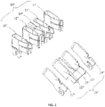
- the adapter 100 has a housing 10, and an input port 20, an output port 30 connected with the input port 20 and a first switching mechanism 40 mounted on the housing 10.
- the housing 10 is provided with a top wall 11, a bottom wall 12 opposite to the top wall 11, a front wall 13 near the input port 20 and the output port 30, a rear wall 14 opposite to the front wall 13, and two side walls 15 on both sides of the top wall 11.
- the top wall 11, the bottom wall 12, the front wall 13, the rear wall 14 and the side walls 15 together define a receiving cavity (not shown) for receiving the input port 20, the output port 30 and the first switching mechanism 40.
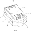
- An output terminal groove 111 communicated with the receiving cavity is arranged at one end of the top wall 11 close to the front wall 13.
- An input terminal groove 131 communicated with the receiving cavity is arranged between the front wall 13 and the bottom wall 12.
- the bottom wall 12 and the side wall 15 together form an inserting slot 151 for sliding insertion of a single-voltage output interface disposed on a single-voltage battery pack or a multi-voltage output interface disposed on a multi-voltage battery pack.
- a sliding rail 152 is formed on a side of the sidewall 15 facing the inserting slot 151 to guide the sliding insertion of the single-voltage battery pack or the multi-voltage battery pack.
- the sliding rail 152 is a groove.
- the sliding rail 152 may also be a protrusion, and the present disclosure is not limited to the specific structure of the sliding rail 152.
- the input port 20 is used to couple with the single-voltage output interface disposed on the single-voltage battery pack or the multi-voltage output interface disposed on the multi-voltage battery pack to obtain an output voltage of the single-voltage battery pack or the multi-voltage battery pack.
- the input port 20 has an input terminal group 21 fixedly installed in the input terminal groove 131 and an input signal terminal 22 movably installed.
- the input terminal group 21 comprises a first input terminal 211, a second input terminal 212, a third input terminal 213, and a fourth input terminal 214, which are sequentially disposed.
- the input signal terminal 22 is located between the second input terminal 212 and the third input terminal 213.
- the input signal terminals 22 are arranged by such way: when the input port 20 is coupled with the single-voltage output interface of the single-voltage battery pack, the input signal terminal 22 at least partially enters the adapter 100 so that the input signal terminal 22 is electrically disconnected from the single-voltage output interface, and the input terminal group 21 is inserted into the single-voltage output interface; when the input port 20 is coupled with the multi-voltage output interface of the multi-voltage battery pack, the input terminal group 21 and the input signal terminal 22 are inserted into the multi-voltage output interface.
- the output port 30 is electrically connected to the input port 20 which is coupled to an input interface provided on a power tool so as to output a voltage to the power tool.
- the output port 30 has an output terminal group 31 mounted in the output terminal groove 111 and an output signal terminal 32.
- the output terminal group 31 is provided with a first output terminal 311, a second output terminal 312, a third output terminal 313 and a fourth output terminal 314, which are sequentially arranged.
- the output signal terminal 32 is located between the second output terminal 312 and the third output terminal 313.
- the first input terminal 211 is electrically connected to the first output terminal 311, the second input terminal 212 is electrically connected to the output signal terminal 32, the fourth input terminal 214 is electrically connected to the fourth output terminal 314, and the input signal terminal 22 is electrically connected to the second output terminal 312.
- the first switching mechanism 40 has a base 41, an elastic element 42, and a connecting terminal 43.
- the input signal terminal 22 is mounted on the base 41; one end of the elastic element 42 is mounted on the base 41, and the other end of the elastic element 42 is mounted on the housing 10; the connecting terminal 43 is mounted on the base 41, the connecting terminal 43 has two ends electrically connected, in the normal state, the connecting terminal 43 electrically connects the second input terminal 212 and the third input terminal 213.
- the input port 20 When the input port 20 is connected to the single-voltage output interface 10' disposed on the single-voltage battery pack, and the output port 30 is connected to a multi-voltage input interface disposed on a power tool, the input signal terminal 22 is abutted against by the single-voltage battery pack and moves along a mating direction of the input port 20 and the single-voltage output interface.
- the input signal terminal 22 at least partially enters into the housing 10, so that the base 41 moves with the input signal terminal 22, at this time, the elastic element 42 is elastically deformed, the connecting terminal 43 is electrically disconnected from the second input terminal 212 and the third input terminal 213, and the input terminal group 21 of the adapter 100 is inserted into the single-voltage output interface 10' of the single-voltage battery pack to obtain the output voltage of the single-voltage battery pack.
- the first input terminal 211 connects with the first output terminal 11'
- the second input terminal 212 connects with the second output terminal 12' (signal terminal)
- the input signal terminal 22 connects with no terminals
- the third input terminal 213 connects with the third output terminal 13' but there is no power transmitted therebetween
- the fourth input terminal 214 connects with the fourth output terminal 14'.
- the input signal terminal 22 does not work, and the first switching mechanism 40 is in a first state;
- the second input terminal 212 serves as a signal terminal and communicates with the power tool via the output signal terminal 32;
- the first input terminal 211 and the fourth input terminal 214 transmit power of the single-voltage battery pack to the power tool having multi-voltage input interface 30" by the first output terminal 311 and the fourth output terminal 314.
- the first switching mechanism 40 When the input port 20 is connected to the multi-voltage output interface 10" provided on the multi-voltage battery pack and the output port 30 is connected to a single-voltage input interface 20' provided on a power tool, the first switching mechanism 40 is in a second state. At this time, the connecting terminal 43 is electrically connected to the second input terminal 212 and the third input terminal 213.
- the first input terminal 211 connects with the first output terminal 11
- the second input terminal 212 connects with the second output terminal 12
- the input signal terminal 22 connects with the output signal terminal 15
- the third input terminal connects with the third output terminal 13
- the fourth output terminal 214 connects with the fourth output terminal 14".
- the input signal terminal 22 works and communicates with the power tool having single-voltage input interface 20' by the second output terminal 312. As the second input terminal 212 and the third input terminal 213 are electrically connected by the connecting terminal 43, the sets of the battery cells accommodated in the multi-voltage battery pack are series connected. Furthermore, the first input terminal 21' of the single-voltage input interface 20' connects with the first output terminal 311 of the adapter 100, the second input terminal 22' (signal terminal) connects with the second output terminal 312, the third input terminal 23' (securing terminal) connects with the third output terminal 313, the fourth input terminal 24' connects with the fourth output terminal 314.
- the first input terminal 211 and the fourth input terminal 214 transmit the first voltage to the power tool having the single-voltage input interface 20' by the first output terminal 311 and the fourth output terminal 314.
- the multi-voltage battery pack is a dual-voltage battery pack
- the first voltage is a series voltage output by the dual-voltage battery pack.
- the connecting terminal 43 is used to electrically connect the second input terminal 212 and the third input terminal 213.
- the connecting terminals 43 may further include a first connecting terminal (not shown) and a second connecting terminal (not shown).
- the first connecting terminal and the second connecting terminal are configured to: when the elastic element 42 is elastically deformed, the first connecting terminal is electrically disconnected from the first input terminal 211 and the second input terminal 212, the second connecting terminal is electrically disconnected from the third input terminal 213 and the fourth input terminal 214, at that time the first switching mechanism 40 is in the first state; when the elastic element 42 resets, the first connecting terminal is electrically connected to the first input terminal 211 and the second input terminal 212, and the second connecting terminal is electrically connected to the third input terminal 213 and the fourth input terminal 214, so that the input port 20 obtains a second voltage output by the multi-voltage battery pack, and at this time, the first switching mechanism 40 is in the second state.
- the multi-voltage battery pack is a dual-voltage battery pack
- the second voltage is a parallel voltage output by the dual-voltage battery pack.
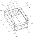
- the base 41 when the elastic element 42 is elastically deformed, the base 41 is configured to move along the mating direction of the input port 20 and the single-voltage output interface of the single voltage battery pack (i.e., direction BB in FIG. 5 ). However, it is understood that in other embodiments, the base 41 may be configured to move in a vertical direction (i.e., direction CC in FIG. 5 ). When the input port 20 is connected to the single-voltage output interface of the single voltage battery pack, the base 41 is vertically retracted into the adapter 100 under the action of the single-voltage battery pack.
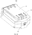
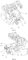
- FIG.7 shows an adapter 200 according to a second embodiment of the invention.
- the adapter 200 has a similar structure as the adapter 100, and comprises a housing 10, an input port 20, an output port 30, an abdicating mechanism 50 and a second switching mechanism 60.
- the housing 10, the input port 20, the output port 30 still use the numerals for the same structures in the adapter 100.
- the abdicating mechanism 50 comprises a base body 51 and an elastic member 52 engaged with the base body 51.
- the input signal terminal 22 is mounted on the base body 51.
- the elastic member 52 has one end mounted on the base body 51 and the other end mounted on the housing 10.
- the input signal terminal 22 When the input port 20 is coupled with the single-voltage output interface 10' arranged on the single-voltage battery pack, the input signal terminal 22 at least partially enters the housing 10 under the butting of the single-voltage battery pack, so that the input signal terminal 22 is electrically disconnected from the single-voltage output interface; at this time, the base body 51 moves under the action of the input signal terminal 22 or the single-voltage battery pack, and elastically deforms the elastic member 52.
- the second switching mechanism 60 comprises a button 61 partially located outside the housing 10 and a switching terminal 62 mounted on the button 61 and engaged with the input terminal group 21.
- the switching terminal 62 comprises a first switching terminal (not shown) and a second switch terminal (not shown), the first switching terminal and the second switching terminal are electrically connected with each other.
- the first switching terminal of the switching terminal 62 connects the second input terminal 212 and the second switching terminal of the switching terminal 62 connects the third input terminal 213 under the action of the button 61, so that the second input terminal 212 and the third input terminal 213 are electrically connected, the input port 20 obtains a first voltage output by the multi-voltage battery pack, and the second switching mechanism 60 is in a second state.
- the multi-voltage battery pack is a dual-voltage battery pack
- the first voltage is a series voltage output by the dual-voltage battery pack.
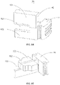
- FIG. 9 shows an alternative embodiment of the second switching mechanism 60 of the second embodiment of the adapter 200.
- An alternative second switching mechanism 70 comprises a button 71, and a first switching terminal 72 and a second switching terminal 73 mounted on the button 71.
- the first switching terminal 72 has two terminals electrically connected
- the second switching terminal 73 has two terminals electrically connected.
- the first switching terminal 72 connects the first input terminal 211 and the second input terminal 212 so that the first input terminal 211 and the second input terminal 212 are electrically connected
- the second switching terminal 73 connects the third input terminal 213 and the fourth input terminal 214 so that the third input terminal 213 and the fourth input terminal 214 are electrically connected, so that the input port 20 obtains a second voltage output by the multi-voltage battery pack
- the second switching mechanism 70 is in a second state.
- the multi-voltage battery pack is a dual-voltage battery pack
- the second voltage is a parallel voltage output by the dual-voltage battery pack.
- the single-voltage input interface 20' of the power tool couples with the output port 30 and is powered by the power output from the dual-voltage battery pack.
- buttons 61, 71 of the switching mechanisms 60, 70 both drive the switching terminal 62 or the first switching terminal 72 and the second switching terminal 73 to move along the mating direction of the input port 20 and the multi-voltage output interface 10" of the multi-voltage battery pack.
- the buttons 61, 71 may be arranged to drive the switch terminal 62 or the first switching terminal 72 and the second switching terminal 73 in a vertical direction (i.e., direction CC in FIG. 5 ).
- FIG. 10 shows an adapter 300 according to a third embodiment of the invention.
- the adapter 300 comprises a housing 10, an input port 80, an output port 30, an abdicating mechanism 50, and a third switching mechanism 90.
- the housing 10, the output port 30 and the abdicating mechanism 50 still use the numerals for the same structures in the adapter 200.
- the input port 80 comprises an input terminal group 81 and an input signal terminal 82.
- the input terminal group 81 comprises a first input terminal 811, a second input terminal 812, a third input terminal 813, and a fourth input terminal 814, which are arranged in this order, and the input signal terminal 82 is located between the second input terminal 812 and the third input terminal 813.
- the first input terminal 811 is electrically connected to the first output terminal 311
- the second input terminal 812 is electrically connected to the output signal terminal 32
- the fourth input terminal 814 is electrically connected to the fourth output terminal 314
- the second output terminal 312 is electrically connected to the input signal terminal 82.
- the first input terminal 811 is provided with a first contact terminal 8111 at an end thereof away from the single-voltage output interface 10' or the multi-voltage output interface 10"
- the second input terminal 812 is provided with a second contact terminal 8121 at an end thereof away from the single-voltage output interface 10' or the multi-voltage output interface 10"
- the third input terminal 813 is provided with a third contact terminal 8131 at an end thereof away from the single-voltage output interface 10' or the multi-voltage output interface 10”
- the fourth input terminal 814 is provided with a fourth contact terminal 8141 at an end thereof away from the single-voltage output interface 10' or the multi-voltage output interface 10".
- the third switching mechanism 90 comprises an operating portion 91 located outside the housing 10 and an abutting portion 92 located inside the housing 10.
- the abutting portion 92 comprises a first abutting portion 921, a second abutting portion 922, and an abdicating groove 923 located between the first abutting portion 921 and the second abutting portion 922, a thickness of the first abutting portion 921 is greater than that of the second abutting portion 922.
- the third switching mechanism 90 When the operating portion 91 is pushed so that the first abutting portion 921 is located between the second contact terminal 8121 and the third contact terminal 8131, the third switching mechanism 90 is in a second state, the second contact terminal 8121 elastically abuts against the first contact terminal 8111 under the action of the first abutting portion 921, and the third contact terminal 8131 elastically abuts against the fourth contact terminal 8141 under the action of the first abutting portion 921.
- the battery sets of the multi-voltage battery pack are paralleled connected. So that the input port 80 obtains a second voltage output by the multi-voltage battery pack and outputs to the output port 30 of the adapter 300.
- the multi-voltage battery pack is a dual-voltage battery pack
- the second voltage is a parallel voltage output by the dual-voltage battery pack, at that time, the first input terminal 811 and the second input terminal 812 are electrically connected, and the third input terminal 813 and the fourth input terminal 814 are electrically connected.
- the third switching mechanism 90 when the operating portion 91 is pushed so that the second abutting portion 922 is located between the second contact terminal 8121 and the third contact terminal 8131, the third switching mechanism 90 is in a first state, the second contact terminal 8121 is electrically disconnected from the first contact terminal 8111 and the third contact terminal 8131 is electrically disconnected from the second contact terminal 8141; in this case, the input port 90 may be connected to the single voltage output port 10' provided on the single voltage battery pack.
- the third switching mechanism 90 when the operation portion 91 is pushed so that the abdicating groove 923 is located between the second contact terminal 8121 and the third contact terminal 8131, the third switching mechanism 90 is in a second state, and the second contact terminal 8121 and the third contact terminal 8131 elastically abut against each other through the abdicating groove 923, so that the input port 80 obtains a first voltage output by the multi-voltage battery pack.
- the second state has two cases, one outputs the first voltage and the other outputs the second voltage.
- the multi-voltage battery pack is a dual-voltage battery pack
- the first voltage is a series voltage output by the dual-voltage battery pack
- the second input terminal 812 and the third input terminal 813 are electrically connected.
- the first abutting portion 921, the second abutting portion 922 and the abdicating groove 923 are vertically arranged, and the operating portion 91 moves vertically.
- the first abutting portion 921, the second abutting portion 922 and the abdicating groove 923 may also be arranged along the mating direction of the input port 80 and the single-voltage output interface, as shown in FIG. 15 ; then, the first abutting portion 921, the second abutting portion 922 and the abdicating groove 923 move along the mating direction of the input port 80 and the single- voltage output interface under the action of the operation portion 91.
- the present disclosure further discloses a tool system 400, which comprises a battery pack 401, a power tool 402, and an adapter 403 connecting the battery pack 401 and the power tool 402.
- the adapter 403 is the adapter 100 or the adapter 200 or the adapter 300.
- the power tool 402 is a power tool provided with a multi-voltage input interface 10"; when the battery pack 401 is a multi-voltage battery pack, the power tool 402 is a power tool provided with a single-voltage input interface 10'.
- the adapters 100, 200 and 300 of the present disclosure can connect the multi-voltage output interface disposed on the multi-voltage battery pack with the power tool having single-voltage input interface, or connect the single-voltage output interface disposed on the single-voltage battery pack with the power tool having multi-voltage input interface, so that the power tool disposed with single-voltage input interface can be powered by the multi-voltage battery pack, and the power tool disposed with multi-voltage input interface can be powered by the single-voltage battery pack, thereby expanding the application range of the single-voltage battery pack and the multi-voltage battery pack.
Landscapes
- Engineering & Computer Science (AREA)
- Mechanical Engineering (AREA)
- Power Engineering (AREA)
- Battery Mounting, Suspending (AREA)
Claims (15)
- Adapter (100; 200; 300), umfassend:einen Eingangsanschluss (20; 80), der mit einer Einzelspannungs-Ausgangsschnittstelle (10') eines Einzelspannungs-Akkupacks oder mit einer Mehrspannungs-Ausgangsschnittstelle (10") eines Mehrspannungs-Akkupacks koppelbar ist;einen Ausgangsanschluss (30), der mit dem Eingangsanschluss (20; 80) elektrisch verbunden ist und mit einer Einzelspannungs-Eingangsschnittstelle (20') eines ersten Elektrowerkzeugs oder mit einer Mehrspannungs-Eingangsschnittstelle (20"; 30") eines zweiten Elektrowerkzeugs koppelbar ist, wobei die Einzelspannungs-Ausgangsschnittstelle (10') des Einzelspannungs-Akkupacks mit der Einzelspannungs-Eingangsschnittstelle (20') des ersten Elektrowerkzeugs koppelbar ist, aber nicht mit der Mehrspannungs-Eingangsschnittstelle (20"; 30") des zweiten Elektrowerkzeugs koppelbar ist, und die Mehrspannungs-Ausgangsschnittstelle (10") des Mehrspannungs-Akkupacks mit der Mehrspannungs-Eingangsschnittstelle (20"; 30") des zweiten Elektrowerkzeugs koppelbar ist, aber nicht mit der Einzelspannungs-Eingangsschnittstelle (20') des ersten Elektrowerkzeugs koppelbar ist;einen Schaltmechanismus (40; 60, 70; 90), der zwischen einem ersten Zustand und einem zweiten Zustand umschaltbar ist; undein Gehäuse (10) zum Aufnehmen des Eingangsanschlusses (20; 80), des Ausgangsanschlusses (30) und des Schaltmechanismus (40; 60, 70; 90);dadurch gekennzeichnet, dassder Adapter so konfiguriert ist, dass, wenn der Eingangsanschluss (20; 80) mit der Einzelspannungs-Ausgangsschnittstelle (10') des Einzelspannungs-Akkupacks gekoppelt ist und der Schaltmechanismus (40; 60, 70; 90) in dem ersten Zustand ist, das zweite Elektrowerkzeug mit dem Ausgangsanschluss (30) koppelbar und von dem Einzelspannungs-Akkupack mit Leistung versorgbar ist, und, wenn der Eingangsanschluss (20; 80) mit der Mehrspannungs-Ausgangsschnittstelle (10") des Mehrspannungs-Akkupacks gekoppelt ist und der Schaltmechanismus (40; 60, 70; 90) in dem zweiten Zustand ist, das erste Elektrowerkzeug mit dem Ausgangsanschluss (30) koppelbar und von dem Mehrspannungs-Akkupack mit Leistung versorgbar ist.
- Adapter (100; 200; 300) nach Anspruch 1, wobei der Eingangsanschluss (20; 80) eine erste Eingangsklemme (211; 811), eine zweite Eingangsklemme (212; 812), eine dritte Eingangsklemme (213; 813) und eine vierte Eingangsklemme (214; 814) umfasst, die in Reihe angeordnet sind.
- Adapter (100) nach Anspruch 2, wobei der Schaltmechanismus (40) eine Basis (41) und ein elastisches Element (42), das mit der Basis (41) in Eingriff steht, und eine Verbindungsklemme (43), die an der Basis (41) angeordnet ist, umfasst; wenn das elastische Element (42) elastisch verformt ist, die Verbindungsklemme (43) elektrisch von der zweiten Eingangsklemme (212) und der dritten Eingangsklemme (213) trennbar ist; wenn das elastische Element (42) entspannt ist, die Verbindungsklemme (43) elektrisch mit der zweiten Eingangsklemme (212) und der dritten Eingangsklemme (213) verbindbar ist.
- Adapter (100) nach Anspruch 2, wobei der Schaltmechanismus (40) eine Basis (41), ein elastisches Element (42), das mit der Basis (41) in Eingriff steht, und eine Vielzahl von Verbindungsklemmen, die an der Basis (41) angeordnet sind, umfasst; die Verbindungsklemmen eine erste Verbindungsklemme und eine zweite Verbindungsklemme umfassen; wenn das elastische Element (42) elastisch verformt ist, die erste Verbindungsklemme elektrisch von der ersten Eingangsklemme (211) und der zweiten Eingangsklemme (212) trennbar ist und die zweite Verbindungsklemme elektrisch von der dritten Eingangsklemme (213) und der vierten Eingangsklemme (214) trennbar ist; wenn das elastische Element (42) entspannt ist, die erste Verbindungsklemme elektrisch mit der ersten Eingangsklemme (211) und der zweiten Eingangsklemme (212) verbindbar ist und die zweite Verbindungsklemme elektrisch mit der dritten Eingangsklemme (213) und der vierten Eingangsklemme (214) verbindbar ist.
- Adapter (100) nach Anspruch 2, wobei der Schaltmechanismus (40) eine Basis (41), ein elastisches Element (42), das mit der Basis (41) in Eingriff steht, und mindestens eine Verbindungsklemme zum Eingriff mit den Eingangsklemmen des Eingangsanschlusses (20) umfasst, wenn das elastische Element (42) elastisch verformt ist, die Basis (41) entlang einer Fügerichtung des Eingangsanschlusses (20) und der Einzelspannungs-Ausgangsschnittstelle (10') oder entlang einer vertikalen Richtung bewegbar ist.
- Adapter (200) nach Anspruch 2, wobei der Schaltmechanismus (60) einen Knopf (60), der teilweise außerhalb des Gehäuses (10) positioniert ist, und eine Schaltklemme (62), die an dem Knopf (60) angebracht ist und mit der Eingangsklemmengruppe (21) in Eingriff steht, umfasst; wenn der Knopf (60) gedrückt wird, die Schaltklemme (62) unter einer Wirkung des Knopfes (60) mit der zweiten Eingangsklemme (212) und der dritten Eingangsklemme (213) in Eingriff bringbar ist, so dass die zweite Eingangsklemme (212) und die dritte Eingangsklemme (213) elektrisch verbindbar sind.
- Adapter (200) nach Anspruch 2, wobei der Schaltmechanismus (70) einen Knopf (71), der teilweise außerhalb des Gehäuses (10) positioniert ist, und eine Vielzahl von Schaltklemmen, die an dem Knopf (71) angeordnet sind und mit der Eingangsklemmengruppe (21) in Eingriff stehen, umfasst; die Schaltklemmen eine erste Schaltklemme (72) und eine zweite Schaltklemme (73) umfassen; wenn der Knopf (71) gedrückt ist, die erste Schaltklemme (72) unter einer Wirkung des Knopfes (71) mit der ersten Eingangsklemme (211) und der zweiten Eingangsklemme (212) in Eingriff bringbar ist, so dass die erste Eingangsklemme (211) und die zweite Eingangsklemme (212) elektrisch verbindbar sind, und die zweite Schaltklemme (73) unter einer Wirkung des Knopfes (71) mit der dritten Eingangsklemme (213) und der vierten Eingangsklemme (214) in Eingriff bringbar ist, so dass die dritte Eingangsklemme (213) und die vierte Eingangsklemme (214) elektrisch verbindbar sind.
- Adapter (300) nach Anspruch 2, wobei die zweite Eingangsklemme (812) mit einer zweiten Kontaktklemme (8121) an einem von der Einzelspannungs-Ausgangsschnittstelle (10') oder der Mehrspannungs-Ausgangsschnittstelle (10") abgewandten Ende davon bereitgestellt ist; die dritte Eingangsklemme (813) mit einer dritten Kontaktklemme (8131) an einem von der Einzelspannungs-Ausgangsschnittstelle (10') oder der Mehrspannungs-Ausgangsschnittstelle (10") abgewandten Ende davon bereitgestellt ist; der Schaltmechanismus (90) mit einer zurücktretenden Nut (923) bereitgestellt ist; die zweite Kontaktklemme (8121) durch die zurücktretende Nut (923) mit der dritten Kontaktklemme (8131) elastisch kontaktierbar ist, um die zweite Eingangsklemme (812) und die dritte Eingangsklemme (813) elektrisch verbindbar zu machen.
- Adapter (300) nach Anspruch 8, wobei der Schaltmechanismus (90) auch mit einem ersten Anschlagabschnitt (921) bereitgestellt ist; wenn sich der erste Anschlagabschnitt (921) zwischen der zweiten Kontaktklemme (8121) und der dritten Kontaktklemme (8131) befindet, die zweite Kontaktklemme (8121) elastisch mit der ersten Eingangsklemme (811) verbindbar ist und die dritte Kontaktklemme (8131) elastisch mit der vierten Eingangsklemme (814) verbindbar ist.
- Adapter (300) nach Anspruch 8, wobei der Schaltmechanismus (90) auch mit einem zweiten Anschlagabschnitt (922) bereitgestellt ist; wenn sich der zweite Anschlagabschnitt (922) zwischen der zweiten Kontaktklemme (8121) und der dritten Kontaktklemme (8131) befindet, die zweite Kontaktklemme (8121) elektrisch von der ersten Eingangsklemme (811) und der dritten Eingangsklemme (813) trennbar ist und die dritte Kontaktklemme (8131) elektrisch von der zweiten Eingangsklemme (812) und der vierten Eingangsklemme (814) trennbar ist.
- Adapter (300) nach Anspruch 8, wobei der Schaltmechanismus (90) entlang einer vertikalen Richtung oder einer Fügerichtung des Eingangsanschlusses (20) und der Einzelspannungs-Ausgangsschnittstelle (10') bewegbar ist.
- Adapter (100) nach Anspruch 1, wobei der Eingangsanschluss (20) eine fest angeordnete Eingangsklemmengruppe (21) und eine beweglich angeordnete Eingangssignalklemme (22) umfasst; wenn der Eingangsanschluss (20) mit der Einzelspannungs-Ausgangsschnittstelle (10') gefügt ist, die Eingangsklemmengruppe (21) in die Einzelspannungs-Ausgangsschnittstelle (10') einführbar ist und die Eingangssignalklemme (22) teilweise in den Adapter einführbar ist, so dass die Eingangssignalklemme (22) elektrisch von der Einzelspannungs-Ausgangsschnittstelle trennbar ist; wenn der Eingangsanschluss (20) mit der Mehrspannungs-Ausgangsschnittstelle (10") gefügt ist, die Eingangsklemmengruppe (21) und die Eingangssignalklemme (22) in die Mehrspannungs-Ausgangsschnittstelle (10") einführbar sind.
- Adapter (100) nach Anspruch 12, wobei die Eingangsklemmengruppe (21) eine erste Eingangsklemme (211), eine zweite Eingangsklemme (212), eine dritte Eingangsklemme (213) und eine vierte Eingangsklemme (214) umfasst, die in Reihe angeordnet sind, und die Eingangssignalklemme (22) zwischen der zweiten Eingangsklemme (212) und der dritten Eingangsklemme (212) positioniert ist; der Ausgangsanschluss (30) eine Ausgangsklemmengruppe (31) und eine Ausgangssignalklemme (32) umfasst; die Ausgangsklemmengruppe (31) eine erste Ausgangsklemme (311), eine zweite Ausgangsklemme (312), eine dritte Ausgangsklemme (313) und eine vierte Ausgangsklemme (314) umfasst, die in Reihe angeordnet sind, und die Ausgangssignalklemme (32) zwischen der zweiten Ausgangsklemme (312) und der dritten Ausgangsklemme (313) positioniert ist; die erste Ausgangsklemme (311) mit der ersten Eingangsklemme (212) verbunden ist, die zweite Ausgangsklemme (312) mit der Eingangssignalklemme (22) verbunden ist, die vierte Ausgangsklemme (314) mit der vierten Eingangsklemme (214) verbunden ist und die zweite Eingangsklemme (212) mit der Ausgangssignalklemme (32) verbunden ist.
- Adapter (100) nach Anspruch 5, wobei der Eingangsanschluss (20) weiter eine Eingangssignalklemme (22) umfasst, die an der Basis (41) angeordnet ist.
- Elektrowerkzeugsystem (400), umfassend:ein Einzelspannungs-Akkupack mit einer Einzelspannungs-Ausgangsschnittstelle (10');und ein erstes Elektrowerkzeug mit einer Einzelspannungs-Eingangsschnittstelle (20'), die mit der Einzelspannungs-Ausgangsschnittstelle (10') des Einzelspannungs-Akkupacks koppelbar ist;gekennzeichnet durchein Mehrspannungs-Akkupack mit einer Mehrspannungs-Ausgangsschnittstelle (10");ein zweites Elektrowerkzeug mit einer Mehrspannungs-Eingangsschnittstelle (20", 30"), die mit der Mehrspannungs-Ausgangsschnittstelle (10") des Mehrspannungs-Akkupacks koppelbar ist, wobei die Einzelspannungs-Ausgangsschnittstelle (10') des Einzelspannungs-Akkupacks nicht mit der Mehrspannungs-Eingangsschnittstelle (20", 30") des zweiten Elektrowerkzeugs koppelbar ist und die Mehrspannungs-Ausgangsschnittstelle (10") des Mehrspannungs-Akkupacks nicht mit der Einzelspannungs-Eingangsschnittstelle (20') des ersten Elektrowerkzeugs koppelbar ist; undeinen Adapter (100, 200, 300) umfassend:einen Eingangsanschluss (20), der mit der Einzelspannungs-Ausgangsschnittstelle (10') des Einzelspannungs-Akkupacks oder der Mehrspannungs-Ausgangsschnittstelle (10") des Mehrspannungs-Akkupacks koppelbar ist;einen Ausgangsanschluss (30), der elektrisch mit dem Eingangsanschluss (20) verbunden ist und mit der Einzelspannungs-Eingangsschnittstelle (20') des ersten Elektrowerkzeugs oder der Mehrspannungs-Eingangsschnittstelle (20", 30") des zweiten Elektrowerkzeugs koppelbar ist;einen Schaltmechanismus (40, 60, 90), der zwischen einem ersten Zustand und einem zweiten Zustand umschaltbar ist;ein Gehäuse (10) zum Aufnehmen des Eingangsanschlusses (20), des Ausgangsanschlusses (30) und des Schaltmechanismus (40, 60, 90);wobei, wenn der Eingangsanschluss (20) mit der Einzelspannungs-Ausgangsschnittstelle (10') des Einzelspannungs-Akkupacks gekoppelt ist und sich der Schaltmechanismus in dem ersten Zustand befindet, das zweite Elektrowerkzeug mit dem Ausgangsanschluss (30) koppelbar ist und von dem Einzelspannungs-Akkupack mit Leistung versorgbar ist, und, wenn der Eingangsanschluss (20) mit der Mehrspannungs-Ausgangsschnittstelle (10") des Mehrspannungs-Akkupacks gekoppelt ist und sich der Schaltmechanismus in dem zweiten Zustand befindet, das erste Elektrowerkzeug mit dem Ausgangsanschluss (30) koppelbar ist und von dem Mehrspannungs-Akkupack mit Leistung versorgbar ist.
Applications Claiming Priority (1)
| Application Number | Priority Date | Filing Date | Title |
|---|---|---|---|
| CN201911271649.6A CN110912240B (zh) | 2019-12-12 | 2019-12-12 | 一种适配器以及电动工具系统 |
Publications (2)
| Publication Number | Publication Date |
|---|---|
| EP3834992A1 EP3834992A1 (de) | 2021-06-16 |
| EP3834992B1 true EP3834992B1 (de) | 2022-04-20 |
Family
ID=69825022
Family Applications (1)
| Application Number | Title | Priority Date | Filing Date |
|---|---|---|---|
| EP20213379.9A Active EP3834992B1 (de) | 2019-12-12 | 2020-12-11 | Adapter und werkzeugmaschinensystem |
Country Status (3)
| Country | Link |
|---|---|
| US (2) | US11309726B2 (de) |
| EP (1) | EP3834992B1 (de) |
| CN (1) | CN110912240B (de) |
Families Citing this family (18)
| Publication number | Priority date | Publication date | Assignee | Title |
|---|---|---|---|---|
| CN110912240B (zh) * | 2019-12-12 | 2025-09-16 | 格力博(江苏)股份有限公司 | 一种适配器以及电动工具系统 |
| CN212323756U (zh) * | 2020-04-13 | 2021-01-08 | 浙江动一新能源动力科技股份有限公司 | 一种转接座与移动电源的连接结构 |
| CN114156958A (zh) * | 2020-09-08 | 2022-03-08 | 南京德朔实业有限公司 | 电池包、采用该电池包的电动工具及电池包供电方法 |
| WO2022172776A1 (ja) * | 2021-02-12 | 2022-08-18 | 工機ホールディングス株式会社 | アダプタ及び電気機器 |
| WO2023093606A1 (zh) * | 2021-11-24 | 2023-06-01 | 格力博(江苏)股份有限公司 | 一种耦合装置及背负式园林工具系统 |
| EP4190502A1 (de) * | 2021-12-01 | 2023-06-07 | Hilti Aktiengesellschaft | Gefederte kontakte in einem teilgehäuse für einen akkumulator |
| EP4190499A1 (de) | 2021-12-01 | 2023-06-07 | Hilti Aktiengesellschaft | System, schnittstelle, werkzeugmaschine und energieversorgungsvorrichtung |
| EP4190498A1 (de) | 2021-12-01 | 2023-06-07 | Hilti Aktiengesellschaft | Systeme, die werkzeugmaschinen und eine energieversorgungsvorrichtungen umfassen, sowie energieversorgungsvorrichtung |
| EP4190501A1 (de) * | 2021-12-01 | 2023-06-07 | Hilti Aktiengesellschaft | Akkumulator mit halte- und aufnahmevorrichtung sowie gefederten anschlusselementen |
| CN114336846B (zh) * | 2021-12-29 | 2024-08-20 | 格力博(江苏)股份有限公司 | 一种电池包安装系统、供电系统及电动工具系统 |
| CN114285134B (zh) * | 2021-12-29 | 2024-11-26 | 格力博(江苏)股份有限公司 | 一种电池包安装系统、供电系统以及电动工具系统 |
| EP4459826A4 (de) * | 2021-12-29 | 2025-12-31 | Globe Jiangsu Co Ltd | System, stromversorgungssystem und elektrowerkzeugsystem |
| CN114336848B (zh) * | 2021-12-29 | 2024-08-30 | 格力博(江苏)股份有限公司 | 一种供电系统和电动工具系统 |
| CN114301131B (zh) * | 2021-12-29 | 2024-08-30 | 格力博(江苏)股份有限公司 | 一种电池包安装系统、供电系统及电动工具系统 |
| CN114285135B (zh) * | 2021-12-29 | 2024-08-20 | 格力博(江苏)股份有限公司 | 一种供电系统和电动工具系统 |
| CN114301132B (zh) * | 2021-12-29 | 2024-11-05 | 格力博(江苏)股份有限公司 | 一种电池包安装系统、供电系统及电动工具系统 |
| CN114336845B (zh) * | 2021-12-29 | 2024-11-26 | 格力博(江苏)股份有限公司 | 一种供电系统和电动工具系统 |
| CN114285133B (zh) * | 2021-12-29 | 2024-08-30 | 格力博(江苏)股份有限公司 | 一种供电系统和电动工具系统 |
Family Cites Families (18)
| Publication number | Priority date | Publication date | Assignee | Title |
|---|---|---|---|---|
| US20070210744A1 (en) * | 2006-03-10 | 2007-09-13 | Watson James B | Adapter for a power tool battery |
| JP5574138B2 (ja) * | 2006-09-19 | 2014-08-20 | 日立工機株式会社 | アダプタ、電池パックとアダプタの組み合わせ、及びそれらを備えた電動工具 |
| KR100918805B1 (ko) * | 2007-11-20 | 2009-09-25 | 김병호 | 대기전력 차단용 스위치 |
| DE102008040061A1 (de) | 2008-07-02 | 2010-01-07 | Robert Bosch Gmbh | Elektrowerkzeugmaschine |
| JP5461221B2 (ja) | 2010-02-12 | 2014-04-02 | 株式会社マキタ | 複数のバッテリパックを電源とする電動工具 |
| JP5491925B2 (ja) * | 2010-03-26 | 2014-05-14 | パナソニック株式会社 | 電動工具 |
| JP5887521B2 (ja) * | 2010-08-04 | 2016-03-16 | パナソニックIpマネジメント株式会社 | 電動工具システム |
| CN202003886U (zh) * | 2010-12-16 | 2011-10-05 | 崧腾企业股份有限公司 | 一种改良的开关总成 |
| EP3146615B1 (de) * | 2014-05-18 | 2020-01-15 | Black & Decker, Inc. | Elektrowerkzeugsystem |
| TWM540412U (zh) * | 2015-11-27 | 2017-04-21 | Shenzhen Xindesheng Electronic Technology Co Ltd | 串列匯流排連接器 |
| KR101857105B1 (ko) * | 2016-07-11 | 2018-05-11 | 이종현 | 전동공구 배터리 호환용 어댑터 |
| WO2018079724A1 (ja) * | 2016-10-31 | 2018-05-03 | 日立工機株式会社 | 電池パック及び電池パックを用いた電気機器 |
| JP2018073663A (ja) * | 2016-10-31 | 2018-05-10 | 日立工機株式会社 | 電池パック |
| WO2018119256A1 (en) * | 2016-12-23 | 2018-06-28 | Black & Decker Inc. | Cordless power tool system |
| CN109860443A (zh) * | 2017-11-30 | 2019-06-07 | 南京德朔实业有限公司 | 一种电池包组件 |
| DE202019100882U1 (de) * | 2019-02-18 | 2019-02-25 | Zhejiang Dingneng Electric Co.,Ltd. | Universal-Akkupaket mit Mehrfachspannungsausgang |
| CN110912240B (zh) * | 2019-12-12 | 2025-09-16 | 格力博(江苏)股份有限公司 | 一种适配器以及电动工具系统 |
| CN211377675U (zh) * | 2019-12-12 | 2020-08-28 | 格力博(江苏)股份有限公司 | 一种适配器以及电动工具系统 |
-
2019
- 2019-12-12 CN CN201911271649.6A patent/CN110912240B/zh active Active
-
2020
- 2020-12-11 EP EP20213379.9A patent/EP3834992B1/de active Active
- 2020-12-12 US US17/120,148 patent/US11309726B2/en active Active
-
2022
- 2022-03-20 US US17/699,166 patent/US11695289B2/en active Active
Also Published As
| Publication number | Publication date |
|---|---|
| CN110912240A (zh) | 2020-03-24 |
| US20220209557A1 (en) | 2022-06-30 |
| US11695289B2 (en) | 2023-07-04 |
| EP3834992A1 (de) | 2021-06-16 |
| US20210184477A1 (en) | 2021-06-17 |
| CN110912240B (zh) | 2025-09-16 |
| US11309726B2 (en) | 2022-04-19 |
Similar Documents
| Publication | Publication Date | Title |
|---|---|---|
| EP3834992B1 (de) | Adapter und werkzeugmaschinensystem | |
| EP3836299B1 (de) | Adapter und werkzeugmaschinensystem | |
| US11417993B2 (en) | Adapter and power tool system | |
| CN201032642Y (zh) | 电动工具电池的适配器 | |
| US6329788B1 (en) | Cordless power tool system | |
| EP1699097B1 (de) | Schnurloses elektrisches Werkzeugsystem | |
| EP2787557B1 (de) | Batteriepacks für Elektrowerkzeuge | |
| US7183745B2 (en) | Adapter for a power tool battery | |
| WO2020006701A1 (en) | Battery charger for multiple battery packs | |
| CN110024228A (zh) | 电动器具的或能量存储器的联接装置 | |
| CN212366135U (zh) | 电池包、工具系统及充电系统 | |
| CN210898615U (zh) | 一种适配器以及电动工具系统 | |
| CN114336848A (zh) | 一种供电系统和电动工具系统 | |
| CN211377675U (zh) | 一种适配器以及电动工具系统 | |
| AU2020100321A4 (en) | Battery pack for a power tool, battery charger for such battery pack, and power tool for such battery pack | |
| CN210898616U (zh) | 一种适配器以及电动工具系统 | |
| CN114285133B (zh) | 一种供电系统和电动工具系统 | |
| CN114285135B (zh) | 一种供电系统和电动工具系统 | |
| CN224138271U (zh) | 一种转换部件、双压电池包和电动工具系统 | |
| CN224138272U (zh) | 一种转换部件、双压电池包和电动工具系统 | |
| CN223333915U (zh) | 一种电池包及电动工具系统 | |
| AU2020102987A4 (en) | Battery charger for multiple battery packs | |
| CN120319987A (zh) | 一种双压电池包和电动工具系统 |
Legal Events
| Date | Code | Title | Description |
|---|---|---|---|
| PUAI | Public reference made under article 153(3) epc to a published international application that has entered the european phase |
Free format text: ORIGINAL CODE: 0009012 |
|
| STAA | Information on the status of an ep patent application or granted ep patent |
Free format text: STATUS: THE APPLICATION HAS BEEN PUBLISHED |
|
| AK | Designated contracting states |
Kind code of ref document: A1 Designated state(s): AL AT BE BG CH CY CZ DE DK EE ES FI FR GB GR HR HU IE IS IT LI LT LU LV MC MK MT NL NO PL PT RO RS SE SI SK SM TR |
|
| STAA | Information on the status of an ep patent application or granted ep patent |
Free format text: STATUS: REQUEST FOR EXAMINATION WAS MADE |
|
| 17P | Request for examination filed |
Effective date: 20210714 |
|
| RBV | Designated contracting states (corrected) |
Designated state(s): AL AT BE BG CH CY CZ DE DK EE ES FI FR GB GR HR HU IE IS IT LI LT LU LV MC MK MT NL NO PL PT RO RS SE SI SK SM TR |
|
| GRAP | Despatch of communication of intention to grant a patent |
Free format text: ORIGINAL CODE: EPIDOSNIGR1 |
|
| STAA | Information on the status of an ep patent application or granted ep patent |
Free format text: STATUS: GRANT OF PATENT IS INTENDED |
|
| INTG | Intention to grant announced |
Effective date: 20220201 |
|
| GRAS | Grant fee paid |
Free format text: ORIGINAL CODE: EPIDOSNIGR3 |
|
| GRAA | (expected) grant |
Free format text: ORIGINAL CODE: 0009210 |
|
| STAA | Information on the status of an ep patent application or granted ep patent |
Free format text: STATUS: THE PATENT HAS BEEN GRANTED |
|
| AK | Designated contracting states |
Kind code of ref document: B1 Designated state(s): AL AT BE BG CH CY CZ DE DK EE ES FI FR GB GR HR HU IE IS IT LI LT LU LV MC MK MT NL NO PL PT RO RS SE SI SK SM TR |
|
| REG | Reference to a national code |
Ref country code: GB Ref legal event code: FG4D |
|
| REG | Reference to a national code |
Ref country code: CH Ref legal event code: EP |
|
| REG | Reference to a national code |
Ref country code: IE Ref legal event code: FG4D |
|
| REG | Reference to a national code |
Ref country code: DE Ref legal event code: R096 Ref document number: 602020002764 Country of ref document: DE |
|
| REG | Reference to a national code |
Ref country code: AT Ref legal event code: REF Ref document number: 1484808 Country of ref document: AT Kind code of ref document: T Effective date: 20220515 |
|
| REG | Reference to a national code |
Ref country code: SE Ref legal event code: TRGR |
|
| REG | Reference to a national code |
Ref country code: LT Ref legal event code: MG9D |
|
| REG | Reference to a national code |
Ref country code: NL Ref legal event code: MP Effective date: 20220420 |
|
| REG | Reference to a national code |
Ref country code: AT Ref legal event code: MK05 Ref document number: 1484808 Country of ref document: AT Kind code of ref document: T Effective date: 20220420 |
|
| PG25 | Lapsed in a contracting state [announced via postgrant information from national office to epo] |
Ref country code: NL Free format text: LAPSE BECAUSE OF FAILURE TO SUBMIT A TRANSLATION OF THE DESCRIPTION OR TO PAY THE FEE WITHIN THE PRESCRIBED TIME-LIMIT Effective date: 20220420 |
|
| PG25 | Lapsed in a contracting state [announced via postgrant information from national office to epo] |
Ref country code: PT Free format text: LAPSE BECAUSE OF FAILURE TO SUBMIT A TRANSLATION OF THE DESCRIPTION OR TO PAY THE FEE WITHIN THE PRESCRIBED TIME-LIMIT Effective date: 20220822 Ref country code: NO Free format text: LAPSE BECAUSE OF FAILURE TO SUBMIT A TRANSLATION OF THE DESCRIPTION OR TO PAY THE FEE WITHIN THE PRESCRIBED TIME-LIMIT Effective date: 20220720 Ref country code: LT Free format text: LAPSE BECAUSE OF FAILURE TO SUBMIT A TRANSLATION OF THE DESCRIPTION OR TO PAY THE FEE WITHIN THE PRESCRIBED TIME-LIMIT Effective date: 20220420 Ref country code: HR Free format text: LAPSE BECAUSE OF FAILURE TO SUBMIT A TRANSLATION OF THE DESCRIPTION OR TO PAY THE FEE WITHIN THE PRESCRIBED TIME-LIMIT Effective date: 20220420 Ref country code: GR Free format text: LAPSE BECAUSE OF FAILURE TO SUBMIT A TRANSLATION OF THE DESCRIPTION OR TO PAY THE FEE WITHIN THE PRESCRIBED TIME-LIMIT Effective date: 20220721 Ref country code: FI Free format text: LAPSE BECAUSE OF FAILURE TO SUBMIT A TRANSLATION OF THE DESCRIPTION OR TO PAY THE FEE WITHIN THE PRESCRIBED TIME-LIMIT Effective date: 20220420 Ref country code: ES Free format text: LAPSE BECAUSE OF FAILURE TO SUBMIT A TRANSLATION OF THE DESCRIPTION OR TO PAY THE FEE WITHIN THE PRESCRIBED TIME-LIMIT Effective date: 20220420 Ref country code: BG Free format text: LAPSE BECAUSE OF FAILURE TO SUBMIT A TRANSLATION OF THE DESCRIPTION OR TO PAY THE FEE WITHIN THE PRESCRIBED TIME-LIMIT Effective date: 20220720 Ref country code: AT Free format text: LAPSE BECAUSE OF FAILURE TO SUBMIT A TRANSLATION OF THE DESCRIPTION OR TO PAY THE FEE WITHIN THE PRESCRIBED TIME-LIMIT Effective date: 20220420 |
|
| PG25 | Lapsed in a contracting state [announced via postgrant information from national office to epo] |
Ref country code: RS Free format text: LAPSE BECAUSE OF FAILURE TO SUBMIT A TRANSLATION OF THE DESCRIPTION OR TO PAY THE FEE WITHIN THE PRESCRIBED TIME-LIMIT Effective date: 20220420 Ref country code: PL Free format text: LAPSE BECAUSE OF FAILURE TO SUBMIT A TRANSLATION OF THE DESCRIPTION OR TO PAY THE FEE WITHIN THE PRESCRIBED TIME-LIMIT Effective date: 20220420 Ref country code: LV Free format text: LAPSE BECAUSE OF FAILURE TO SUBMIT A TRANSLATION OF THE DESCRIPTION OR TO PAY THE FEE WITHIN THE PRESCRIBED TIME-LIMIT Effective date: 20220420 Ref country code: IS Free format text: LAPSE BECAUSE OF FAILURE TO SUBMIT A TRANSLATION OF THE DESCRIPTION OR TO PAY THE FEE WITHIN THE PRESCRIBED TIME-LIMIT Effective date: 20220820 |
|
| REG | Reference to a national code |
Ref country code: DE Ref legal event code: R097 Ref document number: 602020002764 Country of ref document: DE |
|
| PG25 | Lapsed in a contracting state [announced via postgrant information from national office to epo] |
Ref country code: SM Free format text: LAPSE BECAUSE OF FAILURE TO SUBMIT A TRANSLATION OF THE DESCRIPTION OR TO PAY THE FEE WITHIN THE PRESCRIBED TIME-LIMIT Effective date: 20220420 Ref country code: SK Free format text: LAPSE BECAUSE OF FAILURE TO SUBMIT A TRANSLATION OF THE DESCRIPTION OR TO PAY THE FEE WITHIN THE PRESCRIBED TIME-LIMIT Effective date: 20220420 Ref country code: RO Free format text: LAPSE BECAUSE OF FAILURE TO SUBMIT A TRANSLATION OF THE DESCRIPTION OR TO PAY THE FEE WITHIN THE PRESCRIBED TIME-LIMIT Effective date: 20220420 Ref country code: EE Free format text: LAPSE BECAUSE OF FAILURE TO SUBMIT A TRANSLATION OF THE DESCRIPTION OR TO PAY THE FEE WITHIN THE PRESCRIBED TIME-LIMIT Effective date: 20220420 Ref country code: DK Free format text: LAPSE BECAUSE OF FAILURE TO SUBMIT A TRANSLATION OF THE DESCRIPTION OR TO PAY THE FEE WITHIN THE PRESCRIBED TIME-LIMIT Effective date: 20220420 Ref country code: CZ Free format text: LAPSE BECAUSE OF FAILURE TO SUBMIT A TRANSLATION OF THE DESCRIPTION OR TO PAY THE FEE WITHIN THE PRESCRIBED TIME-LIMIT Effective date: 20220420 |
|
| PLBE | No opposition filed within time limit |
Free format text: ORIGINAL CODE: 0009261 |
|
| STAA | Information on the status of an ep patent application or granted ep patent |
Free format text: STATUS: NO OPPOSITION FILED WITHIN TIME LIMIT |
|
| 26N | No opposition filed |
Effective date: 20230123 |
|
| PG25 | Lapsed in a contracting state [announced via postgrant information from national office to epo] |
Ref country code: AL Free format text: LAPSE BECAUSE OF FAILURE TO SUBMIT A TRANSLATION OF THE DESCRIPTION OR TO PAY THE FEE WITHIN THE PRESCRIBED TIME-LIMIT Effective date: 20220420 |
|
| PG25 | Lapsed in a contracting state [announced via postgrant information from national office to epo] |
Ref country code: SI Free format text: LAPSE BECAUSE OF FAILURE TO SUBMIT A TRANSLATION OF THE DESCRIPTION OR TO PAY THE FEE WITHIN THE PRESCRIBED TIME-LIMIT Effective date: 20220420 |
|
| REG | Reference to a national code |
Ref country code: BE Ref legal event code: MM Effective date: 20221231 |
|
| PG25 | Lapsed in a contracting state [announced via postgrant information from national office to epo] |
Ref country code: LU Free format text: LAPSE BECAUSE OF NON-PAYMENT OF DUE FEES Effective date: 20221211 |
|
| PG25 | Lapsed in a contracting state [announced via postgrant information from national office to epo] |
Ref country code: IE Free format text: LAPSE BECAUSE OF NON-PAYMENT OF DUE FEES Effective date: 20221211 |
|
| PG25 | Lapsed in a contracting state [announced via postgrant information from national office to epo] |
Ref country code: BE Free format text: LAPSE BECAUSE OF NON-PAYMENT OF DUE FEES Effective date: 20221231 |
|
| PG25 | Lapsed in a contracting state [announced via postgrant information from national office to epo] |
Ref country code: IT Free format text: LAPSE BECAUSE OF FAILURE TO SUBMIT A TRANSLATION OF THE DESCRIPTION OR TO PAY THE FEE WITHIN THE PRESCRIBED TIME-LIMIT Effective date: 20220420 |
|
| PG25 | Lapsed in a contracting state [announced via postgrant information from national office to epo] |
Ref country code: CY Free format text: LAPSE BECAUSE OF FAILURE TO SUBMIT A TRANSLATION OF THE DESCRIPTION OR TO PAY THE FEE WITHIN THE PRESCRIBED TIME-LIMIT Effective date: 20220420 |
|
| PG25 | Lapsed in a contracting state [announced via postgrant information from national office to epo] |
Ref country code: MK Free format text: LAPSE BECAUSE OF FAILURE TO SUBMIT A TRANSLATION OF THE DESCRIPTION OR TO PAY THE FEE WITHIN THE PRESCRIBED TIME-LIMIT Effective date: 20220420 |
|
| PG25 | Lapsed in a contracting state [announced via postgrant information from national office to epo] |
Ref country code: MC Free format text: LAPSE BECAUSE OF FAILURE TO SUBMIT A TRANSLATION OF THE DESCRIPTION OR TO PAY THE FEE WITHIN THE PRESCRIBED TIME-LIMIT Effective date: 20220420 |
|
| PG25 | Lapsed in a contracting state [announced via postgrant information from national office to epo] |
Ref country code: TR Free format text: LAPSE BECAUSE OF FAILURE TO SUBMIT A TRANSLATION OF THE DESCRIPTION OR TO PAY THE FEE WITHIN THE PRESCRIBED TIME-LIMIT Effective date: 20220420 Ref country code: MC Free format text: LAPSE BECAUSE OF FAILURE TO SUBMIT A TRANSLATION OF THE DESCRIPTION OR TO PAY THE FEE WITHIN THE PRESCRIBED TIME-LIMIT Effective date: 20220420 |
|
| REG | Reference to a national code |
Ref country code: CH Ref legal event code: PL |
|
| PG25 | Lapsed in a contracting state [announced via postgrant information from national office to epo] |
Ref country code: MT Free format text: LAPSE BECAUSE OF FAILURE TO SUBMIT A TRANSLATION OF THE DESCRIPTION OR TO PAY THE FEE WITHIN THE PRESCRIBED TIME-LIMIT Effective date: 20220420 |
|
| PG25 | Lapsed in a contracting state [announced via postgrant information from national office to epo] |
Ref country code: CH Free format text: LAPSE BECAUSE OF NON-PAYMENT OF DUE FEES Effective date: 20231231 |
|
| PG25 | Lapsed in a contracting state [announced via postgrant information from national office to epo] |
Ref country code: CH Free format text: LAPSE BECAUSE OF NON-PAYMENT OF DUE FEES Effective date: 20231231 |
|
| PG25 | Lapsed in a contracting state [announced via postgrant information from national office to epo] |
Ref country code: BG Free format text: LAPSE BECAUSE OF FAILURE TO SUBMIT A TRANSLATION OF THE DESCRIPTION OR TO PAY THE FEE WITHIN THE PRESCRIBED TIME-LIMIT Effective date: 20220420 |
|
| PG25 | Lapsed in a contracting state [announced via postgrant information from national office to epo] |
Ref country code: BG Free format text: LAPSE BECAUSE OF FAILURE TO SUBMIT A TRANSLATION OF THE DESCRIPTION OR TO PAY THE FEE WITHIN THE PRESCRIBED TIME-LIMIT Effective date: 20220420 |
|
| PG25 | Lapsed in a contracting state [announced via postgrant information from national office to epo] |
Ref country code: HU Free format text: LAPSE BECAUSE OF FAILURE TO SUBMIT A TRANSLATION OF THE DESCRIPTION OR TO PAY THE FEE WITHIN THE PRESCRIBED TIME-LIMIT; INVALID AB INITIO Effective date: 20201211 |
|
| PGFP | Annual fee paid to national office [announced via postgrant information from national office to epo] |
Ref country code: GB Payment date: 20251218 Year of fee payment: 6 |
|
| PGFP | Annual fee paid to national office [announced via postgrant information from national office to epo] |
Ref country code: FR Payment date: 20251218 Year of fee payment: 6 |
|
| PGFP | Annual fee paid to national office [announced via postgrant information from national office to epo] |
Ref country code: SE Payment date: 20251217 Year of fee payment: 6 |
|
| PGFP | Annual fee paid to national office [announced via postgrant information from national office to epo] |
Ref country code: DE Payment date: 20251222 Year of fee payment: 6 |