EP3834985B1 - Bearbeitungszentrum und verfahren zur bearbeitung von werkstücken - Google Patents
Bearbeitungszentrum und verfahren zur bearbeitung von werkstücken Download PDFInfo
- Publication number
- EP3834985B1 EP3834985B1 EP20211143.1A EP20211143A EP3834985B1 EP 3834985 B1 EP3834985 B1 EP 3834985B1 EP 20211143 A EP20211143 A EP 20211143A EP 3834985 B1 EP3834985 B1 EP 3834985B1
- Authority
- EP
- European Patent Office
- Prior art keywords
- unit
- additive
- subtractive
- operating axis
- axis
- Prior art date
- Legal status (The legal status is an assumption and is not a legal conclusion. Google has not performed a legal analysis and makes no representation as to the accuracy of the status listed.)
- Active
Links
- 238000003754 machining Methods 0.000 title claims description 108
- 238000000034 method Methods 0.000 title claims description 22
- 239000000654 additive Substances 0.000 claims description 129
- 230000000996 additive effect Effects 0.000 claims description 128
- 238000001125 extrusion Methods 0.000 claims description 76
- 230000008878 coupling Effects 0.000 claims description 53
- 238000010168 coupling process Methods 0.000 claims description 53
- 238000005859 coupling reaction Methods 0.000 claims description 53
- 238000004519 manufacturing process Methods 0.000 claims description 13
- 239000000463 material Substances 0.000 description 23
- 238000010146 3D printing Methods 0.000 description 14
- 238000010438 heat treatment Methods 0.000 description 11
- 239000012530 fluid Substances 0.000 description 5
- 238000003801 milling Methods 0.000 description 5
- 238000001816 cooling Methods 0.000 description 4
- 239000002131 composite material Substances 0.000 description 3
- 239000011265 semifinished product Substances 0.000 description 3
- OKTJSMMVPCPJKN-UHFFFAOYSA-N Carbon Chemical compound [C] OKTJSMMVPCPJKN-UHFFFAOYSA-N 0.000 description 2
- CWYNVVGOOAEACU-UHFFFAOYSA-N Fe2+ Chemical compound [Fe+2] CWYNVVGOOAEACU-UHFFFAOYSA-N 0.000 description 2
- 229910052799 carbon Inorganic materials 0.000 description 2
- 238000005516 engineering process Methods 0.000 description 2
- 229910052751 metal Inorganic materials 0.000 description 2
- 239000002184 metal Substances 0.000 description 2
- 239000004033 plastic Substances 0.000 description 2
- 229920003023 plastic Polymers 0.000 description 2
- 239000002023 wood Substances 0.000 description 2
- 239000004677 Nylon Substances 0.000 description 1
- 239000004952 Polyamide Substances 0.000 description 1
- BQCADISMDOOEFD-UHFFFAOYSA-N Silver Chemical compound [Ag] BQCADISMDOOEFD-UHFFFAOYSA-N 0.000 description 1
- 229910000831 Steel Inorganic materials 0.000 description 1
- RTAQQCXQSZGOHL-UHFFFAOYSA-N Titanium Chemical compound [Ti] RTAQQCXQSZGOHL-UHFFFAOYSA-N 0.000 description 1
- 229920000122 acrylonitrile butadiene styrene Polymers 0.000 description 1
- 239000004676 acrylonitrile butadiene styrene Substances 0.000 description 1
- 239000004411 aluminium Substances 0.000 description 1
- 229910052782 aluminium Inorganic materials 0.000 description 1
- XAGFODPZIPBFFR-UHFFFAOYSA-N aluminium Chemical compound [Al] XAGFODPZIPBFFR-UHFFFAOYSA-N 0.000 description 1
- 239000010941 cobalt Substances 0.000 description 1
- 229910017052 cobalt Inorganic materials 0.000 description 1
- GUTLYIVDDKVIGB-UHFFFAOYSA-N cobalt atom Chemical compound [Co] GUTLYIVDDKVIGB-UHFFFAOYSA-N 0.000 description 1
- 230000006866 deterioration Effects 0.000 description 1
- 239000000975 dye Substances 0.000 description 1
- 230000000694 effects Effects 0.000 description 1
- -1 filaments Substances 0.000 description 1
- PCHJSUWPFVWCPO-UHFFFAOYSA-N gold Chemical compound [Au] PCHJSUWPFVWCPO-UHFFFAOYSA-N 0.000 description 1
- 239000010931 gold Substances 0.000 description 1
- 229910052737 gold Inorganic materials 0.000 description 1
- 239000008187 granular material Substances 0.000 description 1
- 238000009434 installation Methods 0.000 description 1
- 239000007788 liquid Substances 0.000 description 1
- 239000007769 metal material Substances 0.000 description 1
- 229920001778 nylon Polymers 0.000 description 1
- 230000010355 oscillation Effects 0.000 description 1
- 239000008188 pellet Substances 0.000 description 1
- 229920000747 poly(lactic acid) Polymers 0.000 description 1
- 229920002647 polyamide Polymers 0.000 description 1
- 239000004626 polylactic acid Substances 0.000 description 1
- 239000000843 powder Substances 0.000 description 1
- 239000000047 product Substances 0.000 description 1
- 239000011347 resin Substances 0.000 description 1
- 229920005989 resin Polymers 0.000 description 1
- 230000000284 resting effect Effects 0.000 description 1
- 239000004332 silver Substances 0.000 description 1
- 229910052709 silver Inorganic materials 0.000 description 1
- 229910001220 stainless steel Inorganic materials 0.000 description 1
- 239000010959 steel Substances 0.000 description 1
- 229910052719 titanium Inorganic materials 0.000 description 1
- 239000010936 titanium Substances 0.000 description 1
- 230000000007 visual effect Effects 0.000 description 1
- 229910052727 yttrium Inorganic materials 0.000 description 1
Images


Classifications
-
- B—PERFORMING OPERATIONS; TRANSPORTING
- B29—WORKING OF PLASTICS; WORKING OF SUBSTANCES IN A PLASTIC STATE IN GENERAL
- B29C—SHAPING OR JOINING OF PLASTICS; SHAPING OF MATERIAL IN A PLASTIC STATE, NOT OTHERWISE PROVIDED FOR; AFTER-TREATMENT OF THE SHAPED PRODUCTS, e.g. REPAIRING
- B29C64/00—Additive manufacturing, i.e. manufacturing of three-dimensional [3D] objects by additive deposition, additive agglomeration or additive layering, e.g. by 3D printing, stereolithography or selective laser sintering
- B29C64/30—Auxiliary operations or equipment
-
- B—PERFORMING OPERATIONS; TRANSPORTING
- B23—MACHINE TOOLS; METAL-WORKING NOT OTHERWISE PROVIDED FOR
- B23Q—DETAILS, COMPONENTS, OR ACCESSORIES FOR MACHINE TOOLS, e.g. ARRANGEMENTS FOR COPYING OR CONTROLLING; MACHINE TOOLS IN GENERAL CHARACTERISED BY THE CONSTRUCTION OF PARTICULAR DETAILS OR COMPONENTS; COMBINATIONS OR ASSOCIATIONS OF METAL-WORKING MACHINES, NOT DIRECTED TO A PARTICULAR RESULT
- B23Q39/00—Metal-working machines incorporating a plurality of sub-assemblies, each capable of performing a metal-working operation
- B23Q39/02—Metal-working machines incorporating a plurality of sub-assemblies, each capable of performing a metal-working operation the sub-assemblies being capable of being brought to act at a single operating station
- B23Q39/021—Metal-working machines incorporating a plurality of sub-assemblies, each capable of performing a metal-working operation the sub-assemblies being capable of being brought to act at a single operating station with a plurality of toolheads per workholder, whereby the toolhead is a main spindle, a multispindle, a revolver or the like
- B23Q39/022—Metal-working machines incorporating a plurality of sub-assemblies, each capable of performing a metal-working operation the sub-assemblies being capable of being brought to act at a single operating station with a plurality of toolheads per workholder, whereby the toolhead is a main spindle, a multispindle, a revolver or the like with same working direction of toolheads on same workholder
- B23Q39/024—Metal-working machines incorporating a plurality of sub-assemblies, each capable of performing a metal-working operation the sub-assemblies being capable of being brought to act at a single operating station with a plurality of toolheads per workholder, whereby the toolhead is a main spindle, a multispindle, a revolver or the like with same working direction of toolheads on same workholder consecutive working of toolheads
-
- B—PERFORMING OPERATIONS; TRANSPORTING
- B23—MACHINE TOOLS; METAL-WORKING NOT OTHERWISE PROVIDED FOR
- B23P—METAL-WORKING NOT OTHERWISE PROVIDED FOR; COMBINED OPERATIONS; UNIVERSAL MACHINE TOOLS
- B23P23/00—Machines or arrangements of machines for performing specified combinations of different metal-working operations not covered by a single other subclass
- B23P23/04—Machines or arrangements of machines for performing specified combinations of different metal-working operations not covered by a single other subclass for both machining and other metal-working operations
-
- B—PERFORMING OPERATIONS; TRANSPORTING
- B22—CASTING; POWDER METALLURGY
- B22F—WORKING METALLIC POWDER; MANUFACTURE OF ARTICLES FROM METALLIC POWDER; MAKING METALLIC POWDER; APPARATUS OR DEVICES SPECIALLY ADAPTED FOR METALLIC POWDER
- B22F10/00—Additive manufacturing of workpieces or articles from metallic powder
- B22F10/60—Treatment of workpieces or articles after build-up
- B22F10/66—Treatment of workpieces or articles after build-up by mechanical means
-
- B—PERFORMING OPERATIONS; TRANSPORTING
- B22—CASTING; POWDER METALLURGY
- B22F—WORKING METALLIC POWDER; MANUFACTURE OF ARTICLES FROM METALLIC POWDER; MAKING METALLIC POWDER; APPARATUS OR DEVICES SPECIALLY ADAPTED FOR METALLIC POWDER
- B22F12/00—Apparatus or devices specially adapted for additive manufacturing; Auxiliary means for additive manufacturing; Combinations of additive manufacturing apparatus or devices with other processing apparatus or devices
- B22F12/22—Driving means
-
- B—PERFORMING OPERATIONS; TRANSPORTING
- B22—CASTING; POWDER METALLURGY
- B22F—WORKING METALLIC POWDER; MANUFACTURE OF ARTICLES FROM METALLIC POWDER; MAKING METALLIC POWDER; APPARATUS OR DEVICES SPECIALLY ADAPTED FOR METALLIC POWDER
- B22F12/00—Apparatus or devices specially adapted for additive manufacturing; Auxiliary means for additive manufacturing; Combinations of additive manufacturing apparatus or devices with other processing apparatus or devices
- B22F12/80—Plants, production lines or modules
- B22F12/82—Combination of additive manufacturing apparatus or devices with other processing apparatus or devices
-
- B—PERFORMING OPERATIONS; TRANSPORTING
- B23—MACHINE TOOLS; METAL-WORKING NOT OTHERWISE PROVIDED FOR
- B23P—METAL-WORKING NOT OTHERWISE PROVIDED FOR; COMBINED OPERATIONS; UNIVERSAL MACHINE TOOLS
- B23P15/00—Making specific metal objects by operations not covered by a single other subclass or a group in this subclass
-
- B—PERFORMING OPERATIONS; TRANSPORTING
- B23—MACHINE TOOLS; METAL-WORKING NOT OTHERWISE PROVIDED FOR
- B23Q—DETAILS, COMPONENTS, OR ACCESSORIES FOR MACHINE TOOLS, e.g. ARRANGEMENTS FOR COPYING OR CONTROLLING; MACHINE TOOLS IN GENERAL CHARACTERISED BY THE CONSTRUCTION OF PARTICULAR DETAILS OR COMPONENTS; COMBINATIONS OR ASSOCIATIONS OF METAL-WORKING MACHINES, NOT DIRECTED TO A PARTICULAR RESULT
- B23Q5/00—Driving or feeding mechanisms; Control arrangements therefor
- B23Q5/22—Feeding members carrying tools or work
- B23Q5/32—Feeding working-spindles
-
- B—PERFORMING OPERATIONS; TRANSPORTING
- B29—WORKING OF PLASTICS; WORKING OF SUBSTANCES IN A PLASTIC STATE IN GENERAL
- B29C—SHAPING OR JOINING OF PLASTICS; SHAPING OF MATERIAL IN A PLASTIC STATE, NOT OTHERWISE PROVIDED FOR; AFTER-TREATMENT OF THE SHAPED PRODUCTS, e.g. REPAIRING
- B29C64/00—Additive manufacturing, i.e. manufacturing of three-dimensional [3D] objects by additive deposition, additive agglomeration or additive layering, e.g. by 3D printing, stereolithography or selective laser sintering
- B29C64/10—Processes of additive manufacturing
- B29C64/106—Processes of additive manufacturing using only liquids or viscous materials, e.g. depositing a continuous bead of viscous material
-
- B—PERFORMING OPERATIONS; TRANSPORTING
- B29—WORKING OF PLASTICS; WORKING OF SUBSTANCES IN A PLASTIC STATE IN GENERAL
- B29C—SHAPING OR JOINING OF PLASTICS; SHAPING OF MATERIAL IN A PLASTIC STATE, NOT OTHERWISE PROVIDED FOR; AFTER-TREATMENT OF THE SHAPED PRODUCTS, e.g. REPAIRING
- B29C64/00—Additive manufacturing, i.e. manufacturing of three-dimensional [3D] objects by additive deposition, additive agglomeration or additive layering, e.g. by 3D printing, stereolithography or selective laser sintering
- B29C64/20—Apparatus for additive manufacturing; Details thereof or accessories therefor
- B29C64/227—Driving means
-
- B—PERFORMING OPERATIONS; TRANSPORTING
- B33—ADDITIVE MANUFACTURING TECHNOLOGY
- B33Y—ADDITIVE MANUFACTURING, i.e. MANUFACTURING OF THREE-DIMENSIONAL [3-D] OBJECTS BY ADDITIVE DEPOSITION, ADDITIVE AGGLOMERATION OR ADDITIVE LAYERING, e.g. BY 3-D PRINTING, STEREOLITHOGRAPHY OR SELECTIVE LASER SINTERING
- B33Y10/00—Processes of additive manufacturing
-
- B—PERFORMING OPERATIONS; TRANSPORTING
- B33—ADDITIVE MANUFACTURING TECHNOLOGY
- B33Y—ADDITIVE MANUFACTURING, i.e. MANUFACTURING OF THREE-DIMENSIONAL [3-D] OBJECTS BY ADDITIVE DEPOSITION, ADDITIVE AGGLOMERATION OR ADDITIVE LAYERING, e.g. BY 3-D PRINTING, STEREOLITHOGRAPHY OR SELECTIVE LASER SINTERING
- B33Y30/00—Apparatus for additive manufacturing; Details thereof or accessories therefor
-
- B—PERFORMING OPERATIONS; TRANSPORTING
- B33—ADDITIVE MANUFACTURING TECHNOLOGY
- B33Y—ADDITIVE MANUFACTURING, i.e. MANUFACTURING OF THREE-DIMENSIONAL [3-D] OBJECTS BY ADDITIVE DEPOSITION, ADDITIVE AGGLOMERATION OR ADDITIVE LAYERING, e.g. BY 3-D PRINTING, STEREOLITHOGRAPHY OR SELECTIVE LASER SINTERING
- B33Y40/00—Auxiliary operations or equipment, e.g. for material handling
- B33Y40/20—Post-treatment, e.g. curing, coating or polishing
-
- B—PERFORMING OPERATIONS; TRANSPORTING
- B22—CASTING; POWDER METALLURGY
- B22F—WORKING METALLIC POWDER; MANUFACTURE OF ARTICLES FROM METALLIC POWDER; MAKING METALLIC POWDER; APPARATUS OR DEVICES SPECIALLY ADAPTED FOR METALLIC POWDER
- B22F10/00—Additive manufacturing of workpieces or articles from metallic powder
- B22F10/10—Formation of a green body
- B22F10/18—Formation of a green body by mixing binder with metal in filament form, e.g. fused filament fabrication [FFF]
-
- B—PERFORMING OPERATIONS; TRANSPORTING
- B22—CASTING; POWDER METALLURGY
- B22F—WORKING METALLIC POWDER; MANUFACTURE OF ARTICLES FROM METALLIC POWDER; MAKING METALLIC POWDER; APPARATUS OR DEVICES SPECIALLY ADAPTED FOR METALLIC POWDER
- B22F12/00—Apparatus or devices specially adapted for additive manufacturing; Auxiliary means for additive manufacturing; Combinations of additive manufacturing apparatus or devices with other processing apparatus or devices
- B22F12/22—Driving means
- B22F12/222—Driving means for motion along a direction orthogonal to the plane of a layer
-
- B—PERFORMING OPERATIONS; TRANSPORTING
- B22—CASTING; POWDER METALLURGY
- B22F—WORKING METALLIC POWDER; MANUFACTURE OF ARTICLES FROM METALLIC POWDER; MAKING METALLIC POWDER; APPARATUS OR DEVICES SPECIALLY ADAPTED FOR METALLIC POWDER
- B22F12/00—Apparatus or devices specially adapted for additive manufacturing; Auxiliary means for additive manufacturing; Combinations of additive manufacturing apparatus or devices with other processing apparatus or devices
- B22F12/22—Driving means
- B22F12/224—Driving means for motion along a direction within the plane of a layer
-
- B—PERFORMING OPERATIONS; TRANSPORTING
- B22—CASTING; POWDER METALLURGY
- B22F—WORKING METALLIC POWDER; MANUFACTURE OF ARTICLES FROM METALLIC POWDER; MAKING METALLIC POWDER; APPARATUS OR DEVICES SPECIALLY ADAPTED FOR METALLIC POWDER
- B22F12/00—Apparatus or devices specially adapted for additive manufacturing; Auxiliary means for additive manufacturing; Combinations of additive manufacturing apparatus or devices with other processing apparatus or devices
- B22F12/22—Driving means
- B22F12/226—Driving means for rotary motion
-
- B—PERFORMING OPERATIONS; TRANSPORTING
- B22—CASTING; POWDER METALLURGY
- B22F—WORKING METALLIC POWDER; MANUFACTURE OF ARTICLES FROM METALLIC POWDER; MAKING METALLIC POWDER; APPARATUS OR DEVICES SPECIALLY ADAPTED FOR METALLIC POWDER
- B22F12/00—Apparatus or devices specially adapted for additive manufacturing; Auxiliary means for additive manufacturing; Combinations of additive manufacturing apparatus or devices with other processing apparatus or devices
- B22F12/50—Means for feeding of material, e.g. heads
- B22F12/52—Hoppers
-
- B—PERFORMING OPERATIONS; TRANSPORTING
- B23—MACHINE TOOLS; METAL-WORKING NOT OTHERWISE PROVIDED FOR
- B23Q—DETAILS, COMPONENTS, OR ACCESSORIES FOR MACHINE TOOLS, e.g. ARRANGEMENTS FOR COPYING OR CONTROLLING; MACHINE TOOLS IN GENERAL CHARACTERISED BY THE CONSTRUCTION OF PARTICULAR DETAILS OR COMPONENTS; COMBINATIONS OR ASSOCIATIONS OF METAL-WORKING MACHINES, NOT DIRECTED TO A PARTICULAR RESULT
- B23Q2230/00—Special operations in a machine tool
- B23Q2230/002—Using the spindle for performing a non machining or non measuring operation, e.g. cleaning, actuating a mechanism
-
- Y—GENERAL TAGGING OF NEW TECHNOLOGICAL DEVELOPMENTS; GENERAL TAGGING OF CROSS-SECTIONAL TECHNOLOGIES SPANNING OVER SEVERAL SECTIONS OF THE IPC; TECHNICAL SUBJECTS COVERED BY FORMER USPC CROSS-REFERENCE ART COLLECTIONS [XRACs] AND DIGESTS
- Y02—TECHNOLOGIES OR APPLICATIONS FOR MITIGATION OR ADAPTATION AGAINST CLIMATE CHANGE
- Y02P—CLIMATE CHANGE MITIGATION TECHNOLOGIES IN THE PRODUCTION OR PROCESSING OF GOODS
- Y02P10/00—Technologies related to metal processing
- Y02P10/25—Process efficiency
Definitions
- the invention relates to a numerically controlled machining centre, to perform subtractive machining on a workpiece (in particular a workpiece made of ferrous metal, carbon or other composite materials, wood), or to perform additive machining.
- the invention refers to a machining centre set up to perform machining by chip removal, such as milling, for example milling of whole workpiece, milling of edges, milling for making a decorative pattern; the machining centre is further set up to perform additive machining, i.e. to produce parts of components or semifinished products by 3D printing techniques.
- a machining centre is known e.g. from Patent Document EP 3 170 620 A1 .
- the machining centre can adopt a subtractive configuration, in which the additive unit is not operating and the subtractive unit can carry a tool for removing material from the workpiece, and at least one additive configuration, in which the motorised subtractive unit is connected to the additive unit with the possibility of driving the additive unit.
- the invention thus relates to a method for picking up, moving and releasing such a unit in the aforesaid machining centre.
- Machining centres are known that are provided with a conveying unit that is movable on a machining plane along an axis X and an axis Y of a tern of axes X, Y, Z arranged transversely, in particular orthogonally, to one another.
- the conveying unit can comprise an upright element, which is mounted slidably on a portal structure of the machining centre.
- the conveying unit is connected to one or more drivable motors to move the conveying unit substantially along the axes X and Y and along another axis Z of the trio of axes X, Y, Z.
- the machining centre further comprises a magazine provided with one or more seats for housing machining devices, like for example a spindle, or an extrusion/3D printing unit.
- the spindle or alternatively the 3D printing device can be connected to the upright element.
- the spindle can be mounted on the upright element, if it is desired to perform subtractive machining, or the extrusion/3D printing unit, if it is desired to perform additive machining.
- the spindle is provided with a connecting grip arranged for housing and/or rotating a work tool.
- the spindle When the spindle is connected to the upright element, the spindle can rotate the tool to perform machining by chip removal from the workpiece.
- the spindle is also motorised, can be adjustable in rotation around two rotation axes, one parallel to one of the axes X or Y, another parallel to the other axis Z.
- the extrusion/3D printing unit can be connected to the upright element when the machining centre adopts an additive configuration.
- the extrusion/3D printing unit is provided with feeding means, comprising for example electric connections, pressure and temperature sensors, heating elements suitable for heating and fluidizing the material, cooling pipes, and so on.
- feeding means comprising for example electric connections, pressure and temperature sensors, heating elements suitable for heating and fluidizing the material, cooling pipes, and so on.
- electric power nevertheless is required to be supplied to the feeding means.
- On the upright element energy supplying means is thus mounted, which is connected manually to the feeding means when the extrusion/3D printing unit is picked up by the conveying unit.
- the time taken by an operator to connect the feeding means to the energy supplying means is significant. Downtime or waiting time is added to this, before the feeding means is ready to perform the additive machining. For example, it is necessary to wait for the heating elements to reach the prescribed operating temperature after they have been connected to the energy supplying means. This translates into longer production times.
- the extrusion/3D printing unit is further provided with pipes for the transit of material to be moulded that are connected to further transit pipes provided on the conveying unit.
- the transit pipes for the material are connected each time the machining centre adopts an additive configuration and are disconnected when the machining centre adopts a subtractive configuration.
- part of the material to be moulded remains inside the pipes and, in contact with the air and the humidity present in the surrounding environment, often deteriorates and thus may not be suitable for being moulded.
- Machining centres comprising a subtractive unit arranged to perform machining by chip removal from a workpiece positioned on the machining plane.
- the subtractive unit is motorized to move along the axes X and/or Y and/or Z.
- the subtractive unit comprises an upright element to which a spindle is connected; the spindle is arranged to rotate a tool for removing chip from the workpiece.
- the machining centre further comprises an additive unit arranged to perform machining by additive production techniques on the machining plane.
- the additive unit is motorized to move along the axes X and/or Y and/or Z.
- the additive unit comprises a hopper arranged to receive and contain, at least temporarily, a quantity of material to be moulded, and an extrusion unit connected to the hopper and arranged to extrude the material machining plane in a heated and fluid state.
- the additive unit can move on the machining plane independently of the subtractive unit.
- Such a machining centre is structurally complex; the costs of stalling and running the subtractive unit and the additive unit are high, and managing the movements of the two units is cumbersome, above all because of the overall dimensions.
- One object of the invention is to improve the machining centres of known type for performing subtractive machining by chip removal or additive machining by 3D printing.
- One object of the invention is to simplify one step of picking up, moving and releasing an additive unit arranged to perform machining by additive production techniques in the machining centre.
- One object of the invention is to reduce the complexity, and the costs of installing and running the machining centre.
- One object of the invention is to reduce downtime, i.e. non-operational/waiting periods, of the machining centre.
- One object of the invention is to provide a machining centre that is able to adopt an additive configuration in which the additive unit and the subtractive unit have overall relatively compact overall dimensions.
- One advantage is to pick up and/or release in a shorter time and in a simplified manner an additive unit arranged to perform machining by additive production techniques.
- One advantage is to prepare the additive unit before the additive unit is picked up by the subtractive unit.
- One advantage is to make available coupling means that is simple to make and drive to couple the subtractive unit and the additive unit in an operating step.
- One advantage is to preserve over time and avoid deterioration of the material that is suitable for being moulded by additive production techniques.
- a machining centre comprises a subtractive unit arranged to perform chip removal on a workpiece positioned on a machining plane, the subtractive unit comprising a first carriage that is slidable along an operating axis and is connected to a motor unit that is drivable to move the motor unit along this axis.
- the machining centre further comprises an additive unit arranged to perform machining by additive production techniques on the machining plane, the additive unit comprising a second carriage that is slidable along the same operating axis as the first carriage of the subtractive unit.
- the additive unit is provided with first coupling means and the subtractive unit is provided with second coupling means couplable with the first coupling means; in one operating step the subtractive unit adopts a pick-up configuration in which the first coupling means is coupled with the second coupling means to connect the subtractive unit to the additive unit along this operating axis; in this pick-up configuration the subtractive unit is configured to move the additive unit along this operating axis.
- a method is implemented to pick up and move, in a machining centre, an additive unit arranged to perform machining by additive production techniques; the method comprises the steps of connecting the additive unit to a subtractive unit arranged to perform chip removal from a workpiece, and of moving the subtractive unit connected to the additive unit with respect to the machining plane along at least one operating axis.
- the step of connecting comprises coupling first coupling means, mounted on the additive unit, with second coupling means, mounted on the subtractive unit, substantially parallel to this operating axis.
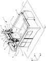
- a numerically controlled machining centre 1 is shown, usable in industries processing ferrous metal, carbon or other composite materials, plastics, wood or another similar material.
- the machining centre 1 may adopt a subtractive configuration, i.e. perform chip removal from a workpiece.
- the machining centre 1 may also adopt an additive configuration, i.e. make an object or a part of an object or components or semifinished products or finished products through an additive 3D printing technology.
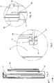
- a machining centre 1 comprising a frame 6 that rests on a resting plane T.
- the frame 6, in a plan view, may have a shape like a quadrilateral, for example the shape of a rectangle.
- the frame 6 may further have a dimension substantially greater than another two dimensions.
- the frame 6 is provided with perimeter walls suitably for bounding a machining plane P on which a workpiece can be arranged, which is not shown, to be machined when the machining centre 1 adopts a subtractive configuration, or on which an object can be made when the machining centre 1 adopts an additive configuration.
- the machining plane P may extend substantially along a pair of operating axes, for example an operating axis X, known below for the sake of simplicity also as axis X, and an operating axis Y, known below for the sake of simplicity also as axis Y.
- the axes X and Y are arranged transversely to one another and parallel to the machining plane P, the axis X and Y being part of a Cartesian tern of axes X, Y, Z.
- a first guide 7 On a wall of the frame 6, for example on a wall extending along the axis X, a first guide 7 may be obtained; in the same manner, on another wall of the frame opposite the aforesaid wall, a second guide 8 may be obtained.
- the first guide 7 and the second guide 8 may be parallel to one another and extend along the axis X.
- the first guide 7 and the second guide 8 may slidably support a portal structure 4, which is movable along the axis X and extends parallel to the axis Y.
- the portal structure 4 is connected to a motor 17 of known type, which is drivable to move the portal structure 4 between two ends of the first 7 and of the second 8 guide.
- the portal structure 4 may have for example an upturned "L" shape, and comprises a crosspiece element 5 operationally positioned above the machining plane P.
- the crosspiece element 5 extends substantially parallel to the axis Y.
- the crosspiece element 5 comprises a wall 9 or on which a third guide 10 and a fourth guide 11 are obtained.
- the third guide 10 and the fourth guide 11 extend substantially parallel to one another and to the axis Y, the third guide 10 is operationally positioned above the fourth guide 11.
- a subtractive unit 2 is mounted slidably.
- the subtractive unit 2 is arranged to perform machining by chip removal from a workpiece positioned on the machining plane P; the subtractive unit 2 is mounted slidably on the portal structure 4 and is motorized to slide along the axis Y and/or along another operating axis Z of the tern of axes X, Y, Z, the other operating axis Z being arranged transversely to the axes X and Y.
- the other operating axis Z can also be called the other axis Z.
- the subtractive unit 2 may comprise a first carriage 12 that is movable along the axis Y; the third guide 10 and the fourth guide 11 support slidably the first carriage 12.
- the first carriage 12 is connected to a motor unit 18 of known type that is drivable to move this first carriage 12 between two ends of the third 10 and fourth 11 guides.
- the first carriage 12 is provided with a fifth guide 13 extending substantially parallel to the other axis Z.
- the subtractive unit 2 comprises an upright element 14 extending parallel to the other axis Z mounted slidably on the fifth guide 13; a connecting member 15 is connected rotatably to the upright element 14 to rotate around a first rotation axis R1.
- the first rotation axis R1 may be oriented parallel to the other axis Z.
- the upright element 14 is connected to another motor unit, which is not shown, that is drivable to slide this upright element 14 on the fifth guide 13; the connecting member 15 is rotatable (by a connection to a motor unit which is not shown) around the axis of rotation R1.
- the subtractive unit 2 may further comprise a spindle 16, for example an electric spindle, connected rotatably to the connecting member 15 by a collar element 39 to rotate around an axis of rotation R2.
- the aforesaid axis of rotation R2 may be parallel to the axis Y.
- the spindle 16 is rotatable around the axis of rotation R2.
- the spindle 16 may comprise a power take-off 52 in which a tool may be housed and rotated, which is not shown, which is suitable for removing chips from the workpiece, for example a milling tool.
- the subtractive unit 2 is a unit with five controlled axes, i.e. the spindle 16 is moved by the subtractive unit 2 substantially along the axis X by the portal structure 4, substantially along the axis Y by the first carriage 12, substantially along the other axis Z by the upright element 14, is rotated around the first rotation axis R1 by the connecting member 15 and rotates around the axis of rotation R2.
- At least one receiving element 19 is mounted receivably, in particular a pair of receiving elements, as shown in Figures 5 and 6 .
- the receiving elements 19 are mounted on two mutually opposite side faces of the spindle 16.
- the receiving element 19 comprises a concave surface 19a.
- the concave surface 19a may be semicircular and may act as a seat for housing an inserting element or a pin, as will be explained below.
- the machining centre 1 further comprises an additive unit 3 arranged to perform machining by additive production techniques on the machining plane P.
- the additive unit 3 is arranged to produce workpieces, components or parts of components or semifinished products, by an additive technology, i.e. by 3D printing.
- the additive unit 3 is mounted on the portal structure 4 and is slidable parallel to the axis Y and to the other axis Z.
- the additive unit 3 comprises a second carriage 20 mounted slidably on the third guide 10 and fourth guide 11 of the crosspiece element 5 and is movable along the axis Y.
- the additive unit 3 further comprises a hopper 21, which can be mounted on the second carriage 20; the hopper 21 is arranged to receive and contain, at least temporarily, a quantity of material that is suitable for being processed by 3D printing.
- the hopper may receive plastics, like nylon, polyamide, ABS, PLA, or metal materials derived from aluminium, cobalt, titanium, gold, silver, stainless steels, composite materials and still others.
- the material may be further in the form of powder, filaments, pellets, granules, resins and so on.
- the aforesaid quantity of material may be standardized and possibly mixed with other materials, additives or dyes.
- a chain 22 may also be fixed arranged to contain feeding means, comprising for example a feeding pipe 23 connected to the hopper 21 and arranged to supply the hopper 21 with material for 3D printing.
- the feeding means may also comprise electric cables, conduits for the transit of pressurized air or for cooling liquids, and so on that for the sake of visual clarity have not been illustrated.
- the hopper 21 may be slidable on the second carriage 20 along the other axis Z.
- the hopper 21 may be slidable on a guide, which is not shown, provided/obtained on the second carriage 20 and extending along the other axis Z.
- the hopper 21 may be provided with braking means arranged to prevent undesired movements of the hopper 21 along the other axis Z.
- the additive unit 3 may comprise an extrusion unit 24 connected to the hopper 21 and arranged to extrude the material to be moulded on the machining plane P in a heated and fluid state.
- the extrusion unit 24 may be connected to the hopper 21 by another feeding pipe 23'.
- the feeding pipe 23' is flexible, as will be clearer subsequently.
- the extrusion unit 24 may comprise a cylindrical container 50 (made for example of nitrided steel) inside which at least one feed screw can rotate, which is not shown, of known type.
- the extrusion unit 24 may comprise heating means, for example electric resistors, arranged to heat the material.
- the heating means may be positioned inside the cylindrical container and near an end portion thereof. Owing to the heat supplied by the heating means and by the heat generated by the effect of the friction of the material with the inner walls of the cylindrical container 50, the material is taken to a fluid state.
- the extrusion unit 24 may further comprise an extrusion nozzle 51 placed at one end of the cylindrical container 50, from which the material exits in fluid state, and a cooling unit, which is not shown, arranged to cool almost completely the cylindrical container 50. Owing to the cooling unit, the material is made fluid substantially in the end portion where the heating means acts.
- the heating means may be positioned near the extrusion nozzle 51.
- the extrusion unit 24 is peripherally provided with protrusions, for example at least one protruding element extends parallel to the axis X and will be indicated by the numeric reference 34, at least another protruding element extends parallel to the axis Y and will be indicated by the numeric reference 34'.
- the extrusion unit 24 may comprise (with reference to the other axis Z) a connecting portion 54 on a lower face thereof; this connecting portion is arranged to removably engage the power take-off 52 of the spindle 16, as will be explained below.
- the extrusion unit further comprises speed reducing members arranged to transmit the motion from the connecting portion 54 to the feed screw.
- the speed reducing members may for example comprise belts, pulleys, chains, and cogs.
- the extrusion unit 24 may further comprise peripherally a pair of inserting elements 53, extending parallel to the other axis Z and sized to engage removably the receiving element 19 of the spindle 16, in particular the concave surface 19a, during one operating step, as will be explained below.
- the inserting elements 53 may comprise tubular elements, for example pins.
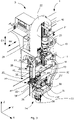
- Said additive unit 3 comprises a locking assembly 25 arranged to keep gripped and locked in position the extrusion unit 24, i.e. to prevent movement along the tern of axes X, Y, Z.
- the locking assembly 25 may further adopt a release configuration in which it frees the extrusion unit 24.
- the locking assembly 25 is movable between a locking configuration in which it locks in position the extrusion unit 24 and a release configuration in which it releases the aforesaid extrusion unit 24.
- the locking assembly is fixed to the second carriage 20 and is connected to the extrusion unit 24.
- the locking assembly 25 may comprise a first actuator 26 fixed to the second carriage 20 and extending along the other axis Z.
- the first actuator 26 may comprise an actuator of linear type, of mechanical type, or hydraulic type and so on.
- the first actuator 26 may comprise a stem 40, arranged inside a cylinder 41, and movable along a first sliding direction D1 parallel to the other axis Z. The first actuator 26 is thus drivable for moving the stem 40 in the first sliding direction D1 between two ends thereof.
- the locking assembly 25 may further comprise a second actuator 27 connected to the first actuator 26 and arranged transversely to the latter.
- the second actuator may extend in a second sliding direction D2 parallel to the axis Y and may be structurally the same as the first actuator 26.
- the second actuator 27 thus comprises a stem 40' that is movable inside a cylinder 41'.
- the second actuator 27 is thus drivable for moving the stem 40' in the second sliding direction D2 between two ends of the cylinder 41'.
- the second actuator 27 may be connected to the first actuator 26 by an elongated element 28 that extends parallel to the other axis Z.
- a face of the elongated element 28 may be connected (in a fixed manner) to an end portion of the stem 40 of the first actuator 26, and another face of the elongated element 28, may be connected (in a fixed manner) to an end portion of the stem 40' of the second actuator 27.
- the two faces of the elongated element 28 connected to the actuators may be mutually opposite.
- the elongated element 28 may extend parallel to the other axis Z, a face 29 of the elongated element 28 may be connected to an end of the stem 40 of the first actuator 26 by a first blade 30, oriented parallel to the axis Y.
- a through hole may be obtained that is sized to insert the end of the stem 40.
- the stem 40 may be further fixed to the hole by fixing means, for example bolts or similar elements.
- the other face of the elongated element 28, which is not shown and opposite the face 29, may be connected to an end of the stem 40' of the second actuator 27 by a second blade 31 oriented transversely to the second actuator 27, for example parallel to the pair of axes X, Z.
- the second blade 31 may be fixed to the other face of the elongated element 28 by fixing means, for example screws and similar elements; on the second blade 31 a through hole may be obtained that is sized for inserting the end of the stem 40' of the second actuator unit 27 by fixing means, for example bolts or similar elements.
- the stem 40' of the second actuator 27 is locked in position; when the second actuator 27 is driven, the cylinder 41' thereof is free to move in the second sliding direction D2.
- the locking assembly 25 may further comprise a supporting member 32 connected to the second actuator unit 27.
- the supporting member 32 may have a "U"-shaped plan shape; the supporting member 32 may comprise a base portion 36 extending parallel to the axis X and two arm portions 37 extending parallel to the axis Y, one of which is shown in Figure 3 .
- the supporting member 32 may be fixed to the second actuator unit 27, for example to the cylinder 41' of the second actuator unit 27.
- the supporting member 32 is fixed to the second actuator unit by at least one third blade 33 shaped for example as an "L".
- a face of the third blade 33 may be in fact fixed to the cylinder 41' of the second actuator unit 27 and another face may be fixed to the supporting member 32 by known fixing means, for example screws, bolts and the like.
- the supporting member 32 is provided with locking means 35, 38 arranged to lock and maintain in position said extrusion unit, in particular to engage the protruding elements 34, 34' of the extrusion unit 24 that have been disclosed previously, so as to prevent undesired movements thereof, as explained below.
- the locking means is mounted on the base portion 36 and/or on the arm portions 37, the locking means may comprise a plate 35 mounted on/fixed to the base portion 36 and extending parallel to the other axis Z. On the plate 35, a through slot is obtained arranged to engage the protruding element 34' provided on the perimeter of the extrusion unit 24 that extends parallel to the axis Y.
- the locking means may further comprise a hook plate 38 having a hook-shaped end portion shaped for engaging the protruding element 34 provided on the perimeter of the extrusion unit 24 that extends parallel to the axis X.
- the first actuator 26 and the second actuator 27 are drivable along the first sliding direction D1 and/or along the second sliding direction D2 to move the supporting member 32 between a locking configuration, in which the locking means, respectively the plate 35 and the hook plate 38, is engaged with the protruding elements 34, 34', preventing the movements of the extrusion unit 24 (for example undesired oscillations or movements), and a release configuration, in which the locking means 35, 38 is disengaged from the protruding elements 34, 34'.
- the actuating means 26 27 is in fact driven to move the supporting member 32 along the first D1 and/or the second sliding direction D2 so as to move the supporting member 32 away from the extrusion unit 24.
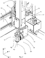
- the additive unit 3 is provided with first coupling means and the subtractive unit 2 is provided with second coupling means; the latter is couplable with the first coupling means.
- the subtractive unit 2 adopts a pick-up configuration in which it is connected to the additive unit 3.
- the first coupling means is coupled with the second coupling means.
- the subtractive unit 2, connected to the additive unit 3, is configured to move the additive unit 3 along the axis Y and/or along the other axis Z, as explained below. Further, the additive unit 3 is moved, connected to the subtractive unit 2 along the axis X by the portal structure 4.
- the first coupling means may comprise an actuator unit comprising for example a hollow body 43, for example a cylinder, and a piston 44.
- the actuator unit may be of the mechanical, hydraulic, pneumatic, electromechanical type and so on.
- the piston 44 may be housed in the hollow body 43 and may be movable inside the hollow body 43 along a direction parallel to the other axis Z.
- the piston 44 may have for example a cylindrical shape, or a frustoconical shape, or a pyramid shape.
- the piston 44 is movable inside the hollow body 43 between a lowered configuration in the piston 44 is substantially contained inside the hollow body 43 and a raised configuration in which the piston 44 protrudes from the hollow body 43. In the said operating step, the piston 44 adopts the raised configuration.
- the hollow body 43/piston 44 may, by way of non-limiting example, be connected to/mounted on the second carriage 20.
- the hollow body 43/piston 44 may be connected to/mounted on the hopper 21.
- the second coupling means comprises a covering element 45 that may be mounted on the upright element 14, or alternatively on the first carriage 12.
- the covering element 45 may comprise a surface facing the machining plane P, on this surface, a recess 49 is defined having a set measured depth parallel to the other axis Z.
- the covering element 45 may engage with the piston 44, as explained below.
- the recess 49 is sized to receive internally the piston 44.
- the subtractive unit 2 is nearer the additive unit 3, the covering element 45 is substantially aligned along the other axis Z with the piston 44, the piston 44 is in raised configuration and engaged with the covering element 45, in particular with the recess 49.
- the subtractive unit 2 is connected to the additive unit 3 along the axis Y.
- Moving the subtractive unit 2 along the operating axis Y involves moving the additive unit 3 along the axis Y.
- the first carriage 12 may slide on the third guide 10 and fourth guide 11 of the portal structure 4 and drag with it the second carriage 20. Accordingly, the entire additive unit 3 may move along the operating axis Y.
- the first coupling means further comprises a connecting element 46 extending substantially in a direction parallel to the other axis Z.
- the connecting element 46 may comprise an elongated element, for example a bar or a tubular element.
- the connecting element 46 may be mounted slidably on the second carriage 20 to slide along the other axis Z.
- the connecting element 46 may be further placed at a set distance from the second carriage 20 measured parallel to the axis X (for example by an arm structure, as shown in Figure 3 ).
- the connecting element 46 is connected to the hopper 21.
- the connecting element 46 is provided with at least one protruding portion 47 that extends in a direction parallel to the axis Y.
- the protruding portion 47 may comprise, for example, a tooth.
- the second coupling means comprises a housing plate 48.
- the housing plate 48 is also mounted on the upright element 14; operationally, the housing plate 48 is positioned below the covering element 45 along the other axis Z. Alternatively, it may be mounted on the first carriage 12.
- the housing plate 48 comprises a surface facing the additive unit 3, a notch 42 being defined on said surface having a set depth parallel to the axis Y.
- the housing plate 48 may engage with the protruding portion 47.
- the housing plate 48 is substantially aligned along the axis Y with the protruding portion 47 of the connecting element 46; the notch 42 further receives internally this protruding portion 47.
- the additive unit 3 is connected to the subtractive unit 2 along the other axis Z.
- Moving the subtractive unit 2 along the other axis Z involves moving the additive unit 3 along the other axis Z.
- the upright element 14 by moving along the other axis Z, drags with itself the connecting element 46; accordingly also the hopper 21, the chain 22 and the feeding pipe 23 move along the other axis Z.
- the supporting member 32 is disengaged from the extrusion unit 24; because the first 26 and/or the second actuator 27 have been driven to move the supporting member 32 along the first direction D1 and/or along the second sliding direction D2, and move the supporting member 32 away from the aforesaid extrusion unit 24.
- the extrusion unit 24 is connected to/coupled with the spindle 16, as explained below.
- the spindle 16 is rotated by about 180° around the axis of rotation R2 with respect to the initial configuration; in the initial configuration, the spindle is oriented substantially parallel to the other axis Z and the power take-off 52 thereof faces the machining plane P.
- the power take-off 52 is oriented upwards.
- the extrusion unit 24 is substantially positioned next to the spindle 16, with reference to the axis Y.
- the extrusion unit 24, in particular, is connected stiffly to and engaged with the rotated spindle 16; each inserting element for inserting the pair of inserting elements 53 is engaged with the concave surface 19a of the receiving element 19 of the rotated spindle 16.
- the connecting portion 54 is substantially aligned and engaged, along the other axis Z, with the power take-off 52.
- the rotated spindle 16 drags with itself the extrusion unit 24. Further, as already said previously, the upright element 14 drags with itself the connecting element 46 and the hopper 21, the chain 22 and the feeding pipe 23.
- the distance between the extrusion unit 24 and the hopper 21, measured along the other axis Z, remains substantially constant whilst the hopper 21 and the extrusion unit 24 are moved along the other axis Z.
- the length of the feeding pipe 23' that connects the hopper 21 to the extrusion unit 24 remains substantially unvaried.
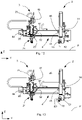
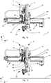
- FIG. 7 shows in fact one step in which the spindle 16 and the extrusion unit 24 are rotated by an angle ⁇ around the axis of rotation R2 with respect to a substantially vertical direction.
- the additive unit 3 is a unit with five controlled axes, even if the movements along these five controlled axes are imposed by the subtractive unit 2.
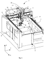
- the operation of the machining centre 1 may actuate a method to pick up and move the additive unit 3 with respect to the machining plane P.
- the method may comprise one step of connecting the additive unit 3 to the subtractive unit 2 as explained below.
- the additive unit 3 and the subtractive unit 2 are mounted slidably on the portal structure 4 that is movable substantially parallel to the axis X of the tern of axes (X, Y, Z) and extends substantially parallel to the axis Y.
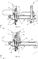
- FIG 12 one embodiment of a part of the machining centre 1 is shown, in particular of the portal structure 4 on which the subtractive unit 2 and the additive unit 3 are mounted slidably.
- the subtractive unit 2 and the additive unit 3 are spaced apart from one another in a direction parallel to the axis Y.
- the spindle 16 is further oriented substantially parallel to the other axis Z and the power take-off 52 faces the machining plane P.
- the extrusion unit 4 is further maintained gripped or locked in position by the locking assembly 25.
- a step is provided of rotating the spindle 16 with respect to the axis of rotation R2 by about 180° such that the spindle 16 is oriented substantially parallel to the other axis Z and the power take-off 52 faces upwards, as shown in figure 13 .
- the step of connecting may comprise the step of sliding the subtractive unit 2 on the portal structure 4 substantially along the operating axis Y to bring the subtractive unit 2 up to the additive unit 3.
- the step of connecting may comprise the step of bringing the subtractive unit 2 into contact with the additive unit 3.
- a step may be provided, for example before the subtractive unit 2 and the additive unit 3 are near, to adjust in position along the other axis Z the extrusion unit 24, or alternatively the spindle 16.
- the extrusion unit 24 is adjusted in position with respect to the spindle 16 (or vice versa) along the other axis Z.
- Adjusting in position may comprise driving the first actuator body 26 to move the locking assembly 25, and thus also the extrusion unit 24, in the first sliding direction D1, downwards or upwards.
- adjusting in position may comprise moving the upright element 14, and accordingly the spindle 16, along the other axis Z.
- the extrusion unit 24 is thus coupled with the spindle 16 (or vice versa) to engage the power take-off 52 with the connecting portion 54 and to insert/engage the inserting elements 53 with the receiving elements 19.
- the extrusion unit 24 and the spindle 16 are connected, i.e. coupled, along the axis Y and along the other axis Z.
- the first coupling means mounted on the additive unit 3 can couple with second coupling means mounted on the subtractive unit 2 along the aforesaid axis Y.
- the housing plate 48 in particular the notch 42, is substantially aligned along the axis Y with the protruding portion 47 of the connecting element 46.
- the protruding portion 47 engages the housing plate, in particular the protruding portion 47 is engaged with the notch 42.
- the protruding portion Being coupled along the operating axis Y, the protruding portion remains engaged in the notch 42 during movements of the subtractive unit 2 along the other operating axis Z; this coupling thus enables the subtractive unit 2 to be connected to the additive unit 3 along this other operating axis Z.
- a step may be provided of adjusting in position this housing plate 48, or this connecting element 46.
- the upright element 14 may be moved along the other axis Z.
- the step of connecting may further comprise the step of coupling the first coupling means with the second coupling means also along the other axis Z.
- the actuator body (comprising the hollow body 43 and the piston 44) is substantially aligned along the other operating axis Z with the covering element 45.
- the actuator body is further near the covering element 45 along this other operating axis Z.
- the piston 44 is substantially aligned with and near the recess 49 along the other axis Z.
- the piston 44 is in the lowered configuration, i.e. it is substantially contained inside the hollow body 43.
- Coupling along the other axis Z thus comprises moving the piston 44 along the other axis Z and engaging the piston 44 with the recess 49 of the covering element 45.
- the piston 44 Being coupled along the other operating axis Z, the piston 44 remains engaged in the recess 49 during movements of the subtractive unit 2 along the operating axis Y; this coupling thus enables the subtractive unit 2 to be connected to the additive unit 3 along this operating axis Y.
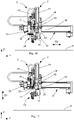
- the step of connecting the subtractive unit 2 with the additive unit 3 further comprises the step of removing and disengaging the locking assembly 25 from the extrusion unit 24.
- the locking assembly 25 is in fact arranged to lock and maintain in position the extrusion unit 24 and prevent a movement thereof along the tern of axes X, Y, Z.
- Moving away the locking assembly 25 comprises moving the supporting member 32 of the locking assembly 25 along the first sliding direction D1 and/or along the second sliding direction D2.
- Moving the supporting member 32 comprises driving the first actuator 26 in the first sliding direction D1 and/or the second actuator 27 in the second sliding direction D2. This step of moving away and disengaging the locking assembly 25 from the extrusion unit 24 is shown in Figures 16 and 17 .
- the step of moving the subtractive unit 2, connected to the additive unit 3, with respect to the machining plane P substantially parallel to the axis Y, and/or to other axis Z of the tern of axes X, Y, Z may be provided.
- the subtractive unit 2 moves with itself the additive unit 3, the latter being devoid of connections to motor units.
- the spindle 16 supplies the extrusion unit 24 for operation thereof.
- the power take-off 52 transmits a rotation motion to the connecting portion 54 and accordingly to the feed screw, which can move the material to be moulded to the extrusion nozzle 51.
- the hopper 21 moves with the upright element 14 by the coupling between the connecting element 46 and the housing plate 48; the extrusion unit 24 further moves with the spindle 16 by the coupling between the inserting elements 53 and the receiving elements 19 (in addition between the power take-off 52 and connecting portion 54).
- Moving the additive unit 3 by the subtractive unit 2 involves moving together substantially all the components of this additive unit, i.e. the second carriage 20, the extrusion unit 24, the hopper 21, the feeding means, the heating means and so on.
- the heating means of the extrusion unit can remain connected to energy supplying means; accordingly, it can be programmed to drive the heating means already for a given time before the additive unit is connected to the subtractive unit, so as to preheat the extrusion unit.
- the material to be deposited on the machining plane remains inside the feeding pipes (in a closed and isolated circuit) when the additive unit is in the rest step; this stops this material from coming into contact with the surrounding environment, for example with the humidity present in the surrounding environment, and getting ruined.
- Moving the additive unit (devoid of motors) by the subtractive unit, and transmitting motion to the extrusion unit by driving the spindle also enables the installation and operation costs of further motor unit to be reduced that are to be connected to this additive unit. Also the overall dimensions are reduced.
Claims (15)
- Bearbeitungszentrum (1), umfassend:- eine Bearbeitungsebene (P);- eine subtraktive Einheit (2), die dazu angeordnet ist, eine Spanabnahme an einem auf der Bearbeitungsebene (P) positionierten Werkstück durchzuführen, wobei die subtraktive Einheit (2) einen ersten Schlitten (12) umfasst, der entlang einer Arbeitsachse (Y) verschiebbar ist, wobei die subtraktive Einheit (2) mit einer Motoreinheit (18) verbunden ist, die so antreibbar ist, dass sie den ersten Schlitten (12) entlang der Arbeitsachse (Y) bewegt;- eine additive Einheit (3), die dazu angeordnet ist, eine Bearbeitung durch additive Fertigungstechniken auf der Bearbeitungsebene (P) durchzuführen, wobei die additive Einheit (3) einen zweiten Schlitten (20) umfasst, der entlang der Arbeitsachse (Y) verschiebbar ist;wobei die additive Einheit (3) mit einem ersten Kopplungsmittel (44, 46, 47) versehen ist und die subtraktive Einheit (2) mit einem zweiten Kopplungsmittel (45, 48) versehen ist, das mit dem ersten Kopplungsmittel (44, 46, 47) koppelbar ist; in einem Arbeitsschritt die subtraktive Einheit (2) eine Aufnahmekonfiguration annimmt, in der das erste Kopplungsmittel (44, 46, 47) mit dem zweiten Kupplungsmittel (45, 48) so gekoppelt ist, dass die subtraktive Einheit (2) mit der additiven Einheit (3) entlang der Arbeitsachse (Y) verbunden ist, wobei die subtraktive Einheit (2) in der Aufnahmekonfiguration so konfiguriert ist, dass sie die additive Einheit (3) entlang der Arbeitsachse (Y) bewegt.
- Bearbeitungszentrum (1) nach Anspruch 1, wobei die subtraktive Einheit (2) ferner entlang einer anderen Arbeitsachse (Z) verschiebbar ist, die quer zur Arbeitsachse (Y) verläuft.
- Bearbeitungszentrum (1) nach Anspruch 2, wobei die subtraktive Einheit (2) mit einer anderen Motoreinheit verbunden ist, die so antreibbar ist, dass sie die subtraktive Einheit (2) entlang der anderen Arbeitsachse (Z) bewegt.
- Bearbeitungszentrum (1) nach Anspruch 2 oder 3, wobei die additive Einheit (3) ferner entlang der anderen Arbeitsachse (Z) verschiebbar ist.
- Bearbeitungszentrum (1) nach einem der Ansprüche 2 bis 4, wobei in der Aufnahmekonfiguration das erste Kopplungsmittel (44, 46, 47) ferner mit dem zweiten Kopplungsmittel (45, 48) so gekoppelt ist, dass die subtraktive Einheit (2) mit der additiven Einheit (3) entlang der anderen Arbeitsachse (Z) verbunden ist; wobei in der Aufnahmekonfiguration die subtraktive Einheit (2) ferner so konfiguriert ist, dass sie die additive Einheit (3) entlang der anderen Arbeitsachse (Z) bewegt.
- Bearbeitungszentrum (1) nach einem der Ansprüche 2 bis 5, wobei die subtraktive Einheit (2) ein aufrechtes Element (14) umfasst, das parallel zu der anderen Arbeitsachse (Z) verschiebbar ist, und wobei die additive Einheit (3) einen Behälter (21), der parallel zu der anderen Arbeitsachse (Z) verschiebbar ist, und ein Zuführungsmittel (23, 23') umfasst, das mit dem Behälter (21) verbunden ist; wobei in dem Arbeitsschritt das aufrechte Element (14) insbesondere mit dem Behälter (21) und dem Zuführungsmittel (23, 23') verbunden ist; wobei in dem Arbeitsschritt das aufrechte Element (14) insbesondere so konfiguriert ist, dass es den Behälter (21) und das Zuführungsmittel (23, 23') entlang der anderen Arbeitsachse (Z) bewegt.
- Bearbeitungszentrum (1) nach einem der Ansprüche 2 bis 6, wobei das erste Kopplungsmittel (44, 46, 47) einen Kolben (44) umfasst, der entlang der anderen Arbeitsachse (Z) bewegbar ist, und das zweite Kopplungsmittel (45, 48) ein Abdeckelement (45) umfasst; wobei in dem Arbeitsschritt der Kolben (44) mit dem Abdeckelement (45) entlang der anderen Arbeitsachse (Z) so in Eingriff steht, dass die subtraktive Einheit (2) mit der additiven Einheit (3) entlang der Arbeitsachse (Y) verbunden ist.
- Bearbeitungszentrum (1) nach einem der Ansprüche 2 bis 7, wobei das erste Kopplungsmittel (44, 46, 47) ferner ein Verbindungselement (46) umfasst, das mit mindestens einem vorstehenden Abschnitt (47) versehen ist, der sich in einer Richtung parallel zu der Arbeitsachse (Y) erstreckt, und das zweite Kopplungsmittel (45, 48) eine Gehäuseplatte (48) umfasst; in dem Arbeitsschritt der vorstehende Abschnitt (47) mit der Gehäuseplatte (48) entlang der Arbeitsachse (Y) so in Eingriff steht, dass die subtraktive Einheit (2) mit der additiven Einheit (3) entlang der anderen Arbeitsachse (Z) verbunden ist.
- Bearbeitungszentrum (1) nach einem der vorhergehenden Ansprüche, wobei die additive Einheit (3) eine Extrusionseinheit (24) und die subtraktive Einheit (2) eine Spindel (16) umfasst, wobei die Spindel (16) in dem Arbeitsschritt mit der Extrusionseinheit (24) gekoppelt ist.
- Bearbeitungszentrum (1) nach Anspruch 9, wobei die additive Einheit (3) eine Verriegelungsanordnung (25) umfasst, die dazu angeordnet ist, dass die Extrusionseinheit (24) aufgenommen und in ihrer Position verriegelt hält; wobei die Verriegelungsanordnung (25) in dem Arbeitsschritt die Extrusionseinheit (24) aus der Aufnahme freigibt.
- Bearbeitungszentrum (1) nach Anspruch 10, wobei die Verriegelungsanordnung (25) ein Stützelement (32), das in Kontakt mit der Extrusionseinheit (24) so angeordnet ist, dass es die Extrusionseinheit (24) aufgenommen hält, und ein Betätigungsmittel (26, 27) umfasst, das mit dem Stützelement (32) verbunden ist; wobei in dem Arbeitsschritt das Betätigungsmittel (26, 27) so angetrieben wird, dass es das Stützelement (32) parallel zu der Arbeitsachse (Y) und/oder einer anderen Arbeitsachse (Z) bewegt, die quer zu der Arbeitsachse (Y) verläuft.
- Bearbeitungszentrum (1) nach Anspruch 11, wobei die Extrusionseinheit (24) am Umfang mit vorstehenden Elementen (34, 34') versehen ist und das Stützelement (32) mit einem Verriegelungsmittel (35, 38) versehen ist, das so geformt ist, dass es mit den vorstehenden Elementen (34, 34') in Eingriff kommt; wobei das Verriegelungsmittel (35, 38) in dem Arbeitsschritt von den vorstehenden Elementen (34, 34') gelöst wird.
- Verfahren zum Aufnehmen und Bewegen einer additiven Einheit (3), die so angeordnet ist, dass sie eine Bearbeitung durch additive Fertigungstechniken auf einer Bearbeitungsebene (P) eines Bearbeitungszentrums (1) durchführt, wobei das Verfahren gekennzeichnet ist durch die Schritte:- Verbinden der additiven Einheit (3) mit einer subtraktiven Einheit (2), die so angeordnet ist, dass sie eine Spanabnahme an einem Werkstück in dem Bearbeitungszentrum (1) durchführt;- Bewegen der subtraktiven Einheit (2), die mit der additiven Einheit (3) verbunden ist, in Bezug auf die Bearbeitungsebene (P) im Wesentlichen parallel zu einer Arbeitsachse (Y);wobei das Verbinden die folgenden Schritte umfasst:- Koppeln eines ersten Kopplungsmittels (44, 46, 47), das an der additiven Einheit (3) angebracht ist, mit einem zweiten Kopplungsmittel (45, 48), das an der subtraktiven Einheit (2) angebracht ist, im Wesentlichen parallel zu der Arbeitsachse (Y);- Koppeln einer Spindel (16) der subtraktiven Einheit (2) mit einer Extrusionseinheit (24) der additiven Einheit (3).
- Verfahren nach Anspruch 13, umfassend den Schritt zum Bewegen der subtraktiven Einheit (2), die mit der additiven Einheit (3) verbunden ist, in Bezug auf die Bearbeitungsebene (P) im Wesentlichen parallel zu einer anderen Arbeitsachse (Z), die quer zur Arbeitsachse (Y) angeordnet ist, wobei das Verbinden den Schritt zum weiteren Koppeln des ersten Kopplungsmittels (44, 46, 47) mit dem zweiten Kopplungsmittel (45, 48) im Wesentlichen parallel zu der anderen Arbeitsachse (Z) umfasst.
- Verfahren nach Anspruch 13 oder 14, wobei das Verbinden der additiven Einheit (3) mit einer subtraktiven Einheit (2) ferner den Schritt zum Freigeben der Extrusionseinheit (24) aus einer Aufnahme einer Verriegelungsanordnung (25) der additiven Einheit (3) umfasst, wobei die Verriegelungsanordnung (25) ein Stützelement (32) umfasst, das in Kontakt mit der Extrusionseinheit (24) so angeordnet ist, dass es die Extrusionseinheit (24) aufgenommen hält; wobei das Lösen von einer Aufnahme insbesondere Bewegen des Stützelements (32) parallel zu der Arbeitsachse (Y) und/oder parallel zu einer anderen Arbeitsachse (Z), die quer zu der Arbeitsachse (Y) angeordnet ist, umfasst.
Applications Claiming Priority (1)
| Application Number | Priority Date | Filing Date | Title |
|---|---|---|---|
| IT102019000023991A IT201900023991A1 (it) | 2019-12-13 | 2019-12-13 | Centro di lavoro e metodo per lavorare pezzi |
Publications (2)
| Publication Number | Publication Date |
|---|---|
| EP3834985A1 EP3834985A1 (de) | 2021-06-16 |
| EP3834985B1 true EP3834985B1 (de) | 2022-07-20 |
Family
ID=70155047
Family Applications (1)
| Application Number | Title | Priority Date | Filing Date |
|---|---|---|---|
| EP20211143.1A Active EP3834985B1 (de) | 2019-12-13 | 2020-12-02 | Bearbeitungszentrum und verfahren zur bearbeitung von werkstücken |
Country Status (6)
| Country | Link |
|---|---|
| US (1) | US11548226B2 (de) |
| EP (1) | EP3834985B1 (de) |
| CN (1) | CN112975415A (de) |
| ES (1) | ES2928936T3 (de) |
| IT (1) | IT201900023991A1 (de) |
| PL (1) | PL3834985T3 (de) |
Citations (45)
| Publication number | Priority date | Publication date | Assignee | Title |
|---|---|---|---|---|
| DE19533960A1 (de) | 1995-09-13 | 1997-03-20 | Fraunhofer Ges Forschung | Verfahren und Vorrichtung zur Herstellung von metallischen Werkstücken |
| CN1207067A (zh) | 1995-12-31 | 1999-02-03 | 株式会社新兴塞尔比克 | 无模成型方法及其装置 |
| DE10148967A1 (de) | 2000-10-05 | 2002-04-18 | Matsushita Electric Works Ltd | Verfahren und Vorrichtung zum Herstellen eines dreidimensionalen Gegenstandes |
| US20040089980A1 (en) | 2002-11-13 | 2004-05-13 | Roland Dg Corporation | Three-dimensional fabrication method and apparatus |
| US20050248065A1 (en) | 2004-05-07 | 2005-11-10 | Koji Owada | 3D modeling device and 3D modeling method for supplying material with high precision |
| JP2007146216A (ja) | 2005-11-25 | 2007-06-14 | Matsushita Electric Works Ltd | 三次元形状造形物製造装置 |
| WO2008146920A1 (ja) | 2007-05-30 | 2008-12-04 | Panasonic Electric Works Co., Ltd. | 積層造形装置 |
| CN103341976A (zh) | 2013-07-22 | 2013-10-09 | 陈功举 | 一种桌面3d打印方法及系统 |
| US8604381B1 (en) | 2006-10-12 | 2013-12-10 | Purdue Research Foundation | Integrated laser material processing cell |
| CN103598938A (zh) | 2013-11-12 | 2014-02-26 | 清华大学 | 一种加式和减式制造结合的仿生结构一体化成形设备 |
| CN104384936A (zh) | 2014-09-18 | 2015-03-04 | 大连理工大学 | 一种增减材复合制造机床 |
| CN104708822A (zh) | 2015-02-13 | 2015-06-17 | 济南爱华达新材料有限公司 | 一种新型多功能数控3d打印设备及使用方法 |
| CN105196063A (zh) | 2015-10-15 | 2015-12-30 | 上海威研精密科技有限公司 | 3d打印与铣削复合机床 |
| CN105415061A (zh) | 2015-12-30 | 2016-03-23 | 大连三垒机器股份有限公司 | 增减复合五轴加工中心机床 |
| CN205342452U (zh) | 2016-02-05 | 2016-06-29 | 哈尔滨鼎智瑞光科技有限公司 | 一种3d打印铣削复合机床 |
| CN105773073A (zh) | 2015-12-30 | 2016-07-20 | 北京航科精机科技有限公司 | 一种增材制造与铣削加工相结合实现制造复杂金属零件的方法 |
| CN105773970A (zh) | 2016-04-12 | 2016-07-20 | 哈尔滨鼎智瑞光科技有限公司 | 一种3d打印铣削复合机床 |
| EP3090811A1 (de) | 2015-03-23 | 2016-11-09 | SCM Group S.p.A. | Bearbeitungszentrum |
| EP3127685A1 (de) | 2014-03-31 | 2017-02-08 | Mitsubishi Heavy Industries, Ltd. | Vorrichtung zur dreidimensionalen laminierung und verfahren zur dreidimensionalen laminierung |
| CN206047583U (zh) | 2016-08-25 | 2017-03-29 | 中山汉通激光设备有限公司 | 一种激光复合加工数控磨床 |
| CN106624826A (zh) | 2017-01-17 | 2017-05-10 | 华南理工大学 | 一种微束等离子3d打印与铣削复合加工设备与方法 |
| CN106799613A (zh) | 2016-12-29 | 2017-06-06 | 大族激光科技产业集团股份有限公司 | 一种激光复合制造设备及复杂零件的加工方法 |
| WO2017110375A1 (ja) | 2015-12-22 | 2017-06-29 | ローランドディー.ジー.株式会社 | 三次元加工装置 |
| WO2017132767A1 (en) | 2016-02-05 | 2017-08-10 | Jing Guo | High-precision manufacturing machine |
| US20170246801A1 (en) | 2014-10-08 | 2017-08-31 | Hewlett-Packard Development Company, L.P. | Additive manufacturing device |
| WO2018003209A1 (ja) | 2016-06-27 | 2018-01-04 | アドバンスト・リサーチ・フォー・マニュファクチャリング・システムズ・リミテッド・ライアビリティ・カンパニー | 金型製造方法、非一時的なコンピュータ読取可能な記憶媒体、およびコントローラ |
| CN107604357A (zh) | 2017-10-19 | 2018-01-19 | 山东豪迈机械科技股份有限公司 | 一种激光熔覆机床及其工作方法与应用 |
| CN107671550A (zh) | 2017-11-22 | 2018-02-09 | 南京捷冉智能科技有限公司 | 多金属电弧式带铣刀3d打印装置及其打印方法 |
| CN207205821U (zh) | 2017-04-14 | 2018-04-10 | 华南理工大学 | 一种熔化极气体保护焊与多轴数控机床3d打印设备 |
| EP3342533A1 (de) | 2016-11-04 | 2018-07-04 | Yamazaki Mazak Corporation | Kombiniertes verarbeitungsvorrichtung und kombiniertes verarbeitungsverfahren |
| EP3363587A1 (de) | 2016-08-17 | 2018-08-22 | Yamazaki Mazak Corporation | Bearbeitungsvorrichtung für verbundstoff und bearbeitungsverfahren für verbundstoff |
| CN207888103U (zh) | 2018-01-25 | 2018-09-21 | 扬州大学 | 一种金属增材制造装置 |
| CN108588707A (zh) | 2018-05-02 | 2018-09-28 | 东北大学 | 一种床身导轨修复装置及其修复方法 |
| US20180326660A1 (en) | 2013-12-19 | 2018-11-15 | Karl Joseph Gifford | Systems and methods for 3D printing with multiple exchangeable printheads |
| CN108857435A (zh) | 2018-06-27 | 2018-11-23 | 浙江师徒智能科技有限公司 | 一种集成3d打印及铣刀功能的复合打印机 |
| WO2018226844A1 (en) | 2017-06-06 | 2018-12-13 | Dmg Mori Advanced Solutions, Inc. | Systems and methods for solidification rate control during additive manufacturing |
| CN109202082A (zh) | 2018-10-25 | 2019-01-15 | 武汉钢铁有限公司 | 增材、等材、减材复合金属3d激光成形装置及其方法 |
| CN109351967A (zh) | 2017-08-06 | 2019-02-19 | 江苏尤尼特激光智能装备有限公司 | 一种增减材激光加工机床及其使用方法 |
| US20190118467A1 (en) | 2015-05-06 | 2019-04-25 | Xioneer Systems Gmbh | Apparatus and method for forming a three-dimensional object |
| CN109940873A (zh) | 2017-12-21 | 2019-06-28 | 北京矩阵空间科技有限公司 | 一种3d打印装置 |
| JP6563622B1 (ja) | 2018-09-06 | 2019-08-21 | ヤマザキマザック株式会社 | 工具保管装置、工作機械及び複合加工機械 |
| CN209289760U (zh) | 2018-11-13 | 2019-08-23 | 上海市机械施工集团有限公司 | 一种龙门式3d增材减材一体化装置 |
| EP3530399A1 (de) | 2018-02-21 | 2019-08-28 | Hamilton Sundstrand Corporation | Indirekte oberflächenbehandlung während der hybriden fertigung |
| US20190270246A1 (en) | 2017-05-16 | 2019-09-05 | Dmg Mori Co., Ltd. | Additive-manufacturing head and manufacturing machine |
| CN110523988A (zh) | 2019-09-29 | 2019-12-03 | 华南理工大学 | 一种四激光四振镜激光选区熔化增减材成型装置与方法 |
Family Cites Families (9)
| Publication number | Priority date | Publication date | Assignee | Title |
|---|---|---|---|---|
| US9964944B2 (en) * | 2014-05-15 | 2018-05-08 | Hurco Companies, Inc. | Material processing unit controlled by rotation |
| DE102014015657A1 (de) * | 2014-10-24 | 2016-04-28 | Heinz Adams | Fräs-Dreh-Materialauftrags-Maschine |
| DE102014224176A1 (de) * | 2014-11-26 | 2016-06-02 | Weeke Bohrsysteme Gmbh | Vorrichtung zur Ausbildung von Volumenkörpern |
| US10065241B2 (en) * | 2015-11-17 | 2018-09-04 | General Electric Company | Combined additive manufacturing and machining system |
| GB2560737A (en) * | 2017-03-22 | 2018-09-26 | Hybrid Manufacturing Tech Limited | A machine tool |
| US11086296B2 (en) * | 2018-01-04 | 2021-08-10 | Hurco Companies, Inc. | Additive manufacturing tool |
| US20220291657A9 (en) * | 2018-09-27 | 2022-09-15 | Additive Alliance, Llc | Multi-tool fabrication machine |
| JP7146576B2 (ja) * | 2018-10-29 | 2022-10-04 | 芝浦機械株式会社 | 積層造形装置、積層造形方法、及びプログラム |
| TWI668073B (zh) | 2018-11-22 | 2019-08-11 | 陳鵬任 | 可連結取料機械手臂單元的cnc銑床 |
-
2019
- 2019-12-13 IT IT102019000023991A patent/IT201900023991A1/it unknown
-
2020
- 2020-12-02 EP EP20211143.1A patent/EP3834985B1/de active Active
- 2020-12-02 ES ES20211143T patent/ES2928936T3/es active Active
- 2020-12-02 PL PL20211143.1T patent/PL3834985T3/pl unknown
- 2020-12-11 CN CN202011459607.8A patent/CN112975415A/zh active Pending
- 2020-12-11 US US17/118,804 patent/US11548226B2/en active Active
Patent Citations (46)
| Publication number | Priority date | Publication date | Assignee | Title |
|---|---|---|---|---|
| DE19533960A1 (de) | 1995-09-13 | 1997-03-20 | Fraunhofer Ges Forschung | Verfahren und Vorrichtung zur Herstellung von metallischen Werkstücken |
| CN1207067A (zh) | 1995-12-31 | 1999-02-03 | 株式会社新兴塞尔比克 | 无模成型方法及其装置 |
| DE10148967A1 (de) | 2000-10-05 | 2002-04-18 | Matsushita Electric Works Ltd | Verfahren und Vorrichtung zum Herstellen eines dreidimensionalen Gegenstandes |
| US20040089980A1 (en) | 2002-11-13 | 2004-05-13 | Roland Dg Corporation | Three-dimensional fabrication method and apparatus |
| US20050248065A1 (en) | 2004-05-07 | 2005-11-10 | Koji Owada | 3D modeling device and 3D modeling method for supplying material with high precision |
| JP2007146216A (ja) | 2005-11-25 | 2007-06-14 | Matsushita Electric Works Ltd | 三次元形状造形物製造装置 |
| US8604381B1 (en) | 2006-10-12 | 2013-12-10 | Purdue Research Foundation | Integrated laser material processing cell |
| WO2008146920A1 (ja) | 2007-05-30 | 2008-12-04 | Panasonic Electric Works Co., Ltd. | 積層造形装置 |
| US20100006228A1 (en) | 2007-05-30 | 2010-01-14 | Satoshi Abe | Lamination shaping apparatus |
| CN103341976A (zh) | 2013-07-22 | 2013-10-09 | 陈功举 | 一种桌面3d打印方法及系统 |
| CN103598938A (zh) | 2013-11-12 | 2014-02-26 | 清华大学 | 一种加式和减式制造结合的仿生结构一体化成形设备 |
| US20180326660A1 (en) | 2013-12-19 | 2018-11-15 | Karl Joseph Gifford | Systems and methods for 3D printing with multiple exchangeable printheads |
| EP3127685A1 (de) | 2014-03-31 | 2017-02-08 | Mitsubishi Heavy Industries, Ltd. | Vorrichtung zur dreidimensionalen laminierung und verfahren zur dreidimensionalen laminierung |
| CN104384936A (zh) | 2014-09-18 | 2015-03-04 | 大连理工大学 | 一种增减材复合制造机床 |
| US20170246801A1 (en) | 2014-10-08 | 2017-08-31 | Hewlett-Packard Development Company, L.P. | Additive manufacturing device |
| CN104708822A (zh) | 2015-02-13 | 2015-06-17 | 济南爱华达新材料有限公司 | 一种新型多功能数控3d打印设备及使用方法 |
| EP3090811A1 (de) | 2015-03-23 | 2016-11-09 | SCM Group S.p.A. | Bearbeitungszentrum |
| US20190118467A1 (en) | 2015-05-06 | 2019-04-25 | Xioneer Systems Gmbh | Apparatus and method for forming a three-dimensional object |
| CN105196063A (zh) | 2015-10-15 | 2015-12-30 | 上海威研精密科技有限公司 | 3d打印与铣削复合机床 |
| WO2017110375A1 (ja) | 2015-12-22 | 2017-06-29 | ローランドディー.ジー.株式会社 | 三次元加工装置 |
| CN105773073A (zh) | 2015-12-30 | 2016-07-20 | 北京航科精机科技有限公司 | 一种增材制造与铣削加工相结合实现制造复杂金属零件的方法 |
| CN105415061A (zh) | 2015-12-30 | 2016-03-23 | 大连三垒机器股份有限公司 | 增减复合五轴加工中心机床 |
| CN205342452U (zh) | 2016-02-05 | 2016-06-29 | 哈尔滨鼎智瑞光科技有限公司 | 一种3d打印铣削复合机床 |
| WO2017132767A1 (en) | 2016-02-05 | 2017-08-10 | Jing Guo | High-precision manufacturing machine |
| CN105773970A (zh) | 2016-04-12 | 2016-07-20 | 哈尔滨鼎智瑞光科技有限公司 | 一种3d打印铣削复合机床 |
| WO2018003209A1 (ja) | 2016-06-27 | 2018-01-04 | アドバンスト・リサーチ・フォー・マニュファクチャリング・システムズ・リミテッド・ライアビリティ・カンパニー | 金型製造方法、非一時的なコンピュータ読取可能な記憶媒体、およびコントローラ |
| EP3363587A1 (de) | 2016-08-17 | 2018-08-22 | Yamazaki Mazak Corporation | Bearbeitungsvorrichtung für verbundstoff und bearbeitungsverfahren für verbundstoff |
| CN206047583U (zh) | 2016-08-25 | 2017-03-29 | 中山汉通激光设备有限公司 | 一种激光复合加工数控磨床 |
| EP3342533A1 (de) | 2016-11-04 | 2018-07-04 | Yamazaki Mazak Corporation | Kombiniertes verarbeitungsvorrichtung und kombiniertes verarbeitungsverfahren |
| CN106799613A (zh) | 2016-12-29 | 2017-06-06 | 大族激光科技产业集团股份有限公司 | 一种激光复合制造设备及复杂零件的加工方法 |
| CN106624826A (zh) | 2017-01-17 | 2017-05-10 | 华南理工大学 | 一种微束等离子3d打印与铣削复合加工设备与方法 |
| CN207205821U (zh) | 2017-04-14 | 2018-04-10 | 华南理工大学 | 一种熔化极气体保护焊与多轴数控机床3d打印设备 |
| US20190270246A1 (en) | 2017-05-16 | 2019-09-05 | Dmg Mori Co., Ltd. | Additive-manufacturing head and manufacturing machine |
| WO2018226844A1 (en) | 2017-06-06 | 2018-12-13 | Dmg Mori Advanced Solutions, Inc. | Systems and methods for solidification rate control during additive manufacturing |
| CN109351967A (zh) | 2017-08-06 | 2019-02-19 | 江苏尤尼特激光智能装备有限公司 | 一种增减材激光加工机床及其使用方法 |
| CN107604357A (zh) | 2017-10-19 | 2018-01-19 | 山东豪迈机械科技股份有限公司 | 一种激光熔覆机床及其工作方法与应用 |
| CN107671550A (zh) | 2017-11-22 | 2018-02-09 | 南京捷冉智能科技有限公司 | 多金属电弧式带铣刀3d打印装置及其打印方法 |
| CN109940873A (zh) | 2017-12-21 | 2019-06-28 | 北京矩阵空间科技有限公司 | 一种3d打印装置 |
| CN207888103U (zh) | 2018-01-25 | 2018-09-21 | 扬州大学 | 一种金属增材制造装置 |
| EP3530399A1 (de) | 2018-02-21 | 2019-08-28 | Hamilton Sundstrand Corporation | Indirekte oberflächenbehandlung während der hybriden fertigung |
| CN108588707A (zh) | 2018-05-02 | 2018-09-28 | 东北大学 | 一种床身导轨修复装置及其修复方法 |
| CN108857435A (zh) | 2018-06-27 | 2018-11-23 | 浙江师徒智能科技有限公司 | 一种集成3d打印及铣刀功能的复合打印机 |
| JP6563622B1 (ja) | 2018-09-06 | 2019-08-21 | ヤマザキマザック株式会社 | 工具保管装置、工作機械及び複合加工機械 |
| CN109202082A (zh) | 2018-10-25 | 2019-01-15 | 武汉钢铁有限公司 | 增材、等材、减材复合金属3d激光成形装置及其方法 |
| CN209289760U (zh) | 2018-11-13 | 2019-08-23 | 上海市机械施工集团有限公司 | 一种龙门式3d增材减材一体化装置 |
| CN110523988A (zh) | 2019-09-29 | 2019-12-03 | 华南理工大学 | 一种四激光四振镜激光选区熔化增减材成型装置与方法 |
Also Published As
| Publication number | Publication date |
|---|---|
| EP3834985A1 (de) | 2021-06-16 |
| US20210178687A1 (en) | 2021-06-17 |
| US11548226B2 (en) | 2023-01-10 |
| PL3834985T3 (pl) | 2022-11-28 |
| CN112975415A (zh) | 2021-06-18 |
| IT201900023991A1 (it) | 2021-06-13 |
| ES2928936T3 (es) | 2022-11-23 |
Similar Documents
| Publication | Publication Date | Title |
|---|---|---|
| EP0348715B1 (de) | Einrichtung zur selbsttätigen Einstellung von auf Werkstückpaletten angeordneten Tragkörpern | |
| CN101312805B (zh) | 机床 | |
| EP2570208A2 (de) | Arbeitsgriffvorrichtung und Arbeitsübertragungsverfahren einer rotierenden Drehmaschine | |
| US5474166A (en) | Automatic adjustment of pallet workpiece support members | |
| JPS6244367A (ja) | ブラウン管前面ガラスの自動研削の方法および装置 | |
| EP3819080B1 (de) | Elektronisch gesteuerte arbeitsstation zur automatisierten verarbeitung von glasplatten oder platten aus stein oder synthetischem material | |
| CN112606432B (zh) | 一种用于复合材料预浸带成型制造的铺带装置 | |
| US7143489B1 (en) | Multiple station tooling machine for manufacturing drill bits and other spirally grooved workpieces | |
| US20090269153A1 (en) | Servo drill spindle | |
| EP3834985B1 (de) | Bearbeitungszentrum und verfahren zur bearbeitung von werkstücken | |
| JP3231671B2 (ja) | 鍛造プレス機のビレット供給装置 | |
| US5946960A (en) | Bending machine for bending pipes and wire-like material in general | |
| US5255778A (en) | Automatic adjustment of pallet workpiece support members | |
| CN210255052U (zh) | 一种机器人控制的螺孔球阀装配机 | |
| CN214869322U (zh) | 一种中型铸件自动打磨设备 | |
| US5099978A (en) | Automatic adjustment of pallet workpiece support members | |
| CN109746355B (zh) | 一种钢索自动断料及铆合装置 | |
| US11806922B2 (en) | CNC machining centre | |
| CN219427821U (zh) | 一种立体蜡镶点钻机 | |
| CN213005356U (zh) | 自适应快速抓取机械手 | |
| CN215283942U (zh) | 一种曲面产品自动上料印刷一体机 | |
| CN218664185U (zh) | 一种工件自动化上料装置 | |
| CN220560842U (zh) | 用于塑封组件的自动组装设备 | |
| CN213969887U (zh) | 一种谐振罩全自动加工设备 | |
| KR200313282Y1 (ko) | 소형 고압용기의 성형장치 |
Legal Events
| Date | Code | Title | Description |
|---|---|---|---|
| PUAI | Public reference made under article 153(3) epc to a published international application that has entered the european phase |
Free format text: ORIGINAL CODE: 0009012 |
|
| STAA | Information on the status of an ep patent application or granted ep patent |
Free format text: STATUS: THE APPLICATION HAS BEEN PUBLISHED |
|
| AK | Designated contracting states |
Kind code of ref document: A1 Designated state(s): AL AT BE BG CH CY CZ DE DK EE ES FI FR GB GR HR HU IE IS IT LI LT LU LV MC MK MT NL NO PL PT RO RS SE SI SK SM TR |
|
| STAA | Information on the status of an ep patent application or granted ep patent |
Free format text: STATUS: REQUEST FOR EXAMINATION WAS MADE |
|
| 17P | Request for examination filed |
Effective date: 20210831 |
|
| RBV | Designated contracting states (corrected) |
Designated state(s): AL AT BE BG CH CY CZ DE DK EE ES FI FR GB GR HR HU IE IS IT LI LT LU LV MC MK MT NL NO PL PT RO RS SE SI SK SM TR |
|
| GRAP | Despatch of communication of intention to grant a patent |
Free format text: ORIGINAL CODE: EPIDOSNIGR1 |
|
| STAA | Information on the status of an ep patent application or granted ep patent |
Free format text: STATUS: GRANT OF PATENT IS INTENDED |
|
| INTG | Intention to grant announced |
Effective date: 20220208 |
|
| GRAS | Grant fee paid |
Free format text: ORIGINAL CODE: EPIDOSNIGR3 |
|
| GRAA | (expected) grant |
Free format text: ORIGINAL CODE: 0009210 |
|
| STAA | Information on the status of an ep patent application or granted ep patent |
Free format text: STATUS: THE PATENT HAS BEEN GRANTED |
|
| AK | Designated contracting states |
Kind code of ref document: B1 Designated state(s): AL AT BE BG CH CY CZ DE DK EE ES FI FR GB GR HR HU IE IS IT LI LT LU LV MC MK MT NL NO PL PT RO RS SE SI SK SM TR |
|
| REG | Reference to a national code |
Ref country code: CH Ref legal event code: EP |
|
| REG | Reference to a national code |
Ref country code: DE Ref legal event code: R096 Ref document number: 602020004095 Country of ref document: DE |
|
| REG | Reference to a national code |
Ref country code: AT Ref legal event code: REF Ref document number: 1505226 Country of ref document: AT Kind code of ref document: T Effective date: 20220815 |
|
| REG | Reference to a national code |
Ref country code: IE Ref legal event code: FG4D |
|
| REG | Reference to a national code |
Ref country code: NL Ref legal event code: FP |
|
| REG | Reference to a national code |
Ref country code: LT Ref legal event code: MG9D |
|
| REG | Reference to a national code |
Ref country code: ES Ref legal event code: FG2A Ref document number: 2928936 Country of ref document: ES Kind code of ref document: T3 Effective date: 20221123 |
|
| PG25 | Lapsed in a contracting state [announced via postgrant information from national office to epo] |
Ref country code: SE Free format text: LAPSE BECAUSE OF FAILURE TO SUBMIT A TRANSLATION OF THE DESCRIPTION OR TO PAY THE FEE WITHIN THE PRESCRIBED TIME-LIMIT Effective date: 20220720 Ref country code: RS Free format text: LAPSE BECAUSE OF FAILURE TO SUBMIT A TRANSLATION OF THE DESCRIPTION OR TO PAY THE FEE WITHIN THE PRESCRIBED TIME-LIMIT Effective date: 20220720 Ref country code: PT Free format text: LAPSE BECAUSE OF FAILURE TO SUBMIT A TRANSLATION OF THE DESCRIPTION OR TO PAY THE FEE WITHIN THE PRESCRIBED TIME-LIMIT Effective date: 20221121 Ref country code: NO Free format text: LAPSE BECAUSE OF FAILURE TO SUBMIT A TRANSLATION OF THE DESCRIPTION OR TO PAY THE FEE WITHIN THE PRESCRIBED TIME-LIMIT Effective date: 20221020 Ref country code: LV Free format text: LAPSE BECAUSE OF FAILURE TO SUBMIT A TRANSLATION OF THE DESCRIPTION OR TO PAY THE FEE WITHIN THE PRESCRIBED TIME-LIMIT Effective date: 20220720 Ref country code: LT Free format text: LAPSE BECAUSE OF FAILURE TO SUBMIT A TRANSLATION OF THE DESCRIPTION OR TO PAY THE FEE WITHIN THE PRESCRIBED TIME-LIMIT Effective date: 20220720 Ref country code: FI Free format text: LAPSE BECAUSE OF FAILURE TO SUBMIT A TRANSLATION OF THE DESCRIPTION OR TO PAY THE FEE WITHIN THE PRESCRIBED TIME-LIMIT Effective date: 20220720 |
|
| REG | Reference to a national code |
Ref country code: AT Ref legal event code: MK05 Ref document number: 1505226 Country of ref document: AT Kind code of ref document: T Effective date: 20220720 |
|
| PG25 | Lapsed in a contracting state [announced via postgrant information from national office to epo] |
Ref country code: IS Free format text: LAPSE BECAUSE OF FAILURE TO SUBMIT A TRANSLATION OF THE DESCRIPTION OR TO PAY THE FEE WITHIN THE PRESCRIBED TIME-LIMIT Effective date: 20221120 Ref country code: HR Free format text: LAPSE BECAUSE OF FAILURE TO SUBMIT A TRANSLATION OF THE DESCRIPTION OR TO PAY THE FEE WITHIN THE PRESCRIBED TIME-LIMIT Effective date: 20220720 Ref country code: GR Free format text: LAPSE BECAUSE OF FAILURE TO SUBMIT A TRANSLATION OF THE DESCRIPTION OR TO PAY THE FEE WITHIN THE PRESCRIBED TIME-LIMIT Effective date: 20221021 |
|
| PGFP | Annual fee paid to national office [announced via postgrant information from national office to epo] |
Ref country code: PL Payment date: 20221020 Year of fee payment: 3 |
|
| REG | Reference to a national code |
Ref country code: DE Ref legal event code: R026 Ref document number: 602020004095 Country of ref document: DE |
|
| PLBI | Opposition filed |
Free format text: ORIGINAL CODE: 0009260 |
|
| PG25 | Lapsed in a contracting state [announced via postgrant information from national office to epo] |
Ref country code: SM Free format text: LAPSE BECAUSE OF FAILURE TO SUBMIT A TRANSLATION OF THE DESCRIPTION OR TO PAY THE FEE WITHIN THE PRESCRIBED TIME-LIMIT Effective date: 20220720 Ref country code: RO Free format text: LAPSE BECAUSE OF FAILURE TO SUBMIT A TRANSLATION OF THE DESCRIPTION OR TO PAY THE FEE WITHIN THE PRESCRIBED TIME-LIMIT Effective date: 20220720 Ref country code: DK Free format text: LAPSE BECAUSE OF FAILURE TO SUBMIT A TRANSLATION OF THE DESCRIPTION OR TO PAY THE FEE WITHIN THE PRESCRIBED TIME-LIMIT Effective date: 20220720 Ref country code: AT Free format text: LAPSE BECAUSE OF FAILURE TO SUBMIT A TRANSLATION OF THE DESCRIPTION OR TO PAY THE FEE WITHIN THE PRESCRIBED TIME-LIMIT Effective date: 20220720 |
|
| PGFP | Annual fee paid to national office [announced via postgrant information from national office to epo] |
Ref country code: ES Payment date: 20230102 Year of fee payment: 3 |
|
| PLAB | Opposition data, opponent's data or that of the opponent's representative modified |
Free format text: ORIGINAL CODE: 0009299OPPO |
|
| PLAX | Notice of opposition and request to file observation + time limit sent |
Free format text: ORIGINAL CODE: EPIDOSNOBS2 |
|
| PLAN | Information deleted related to communication of a notice of opposition and request to file observations + time limit |
Free format text: ORIGINAL CODE: EPIDOSDOBS2 |
|
| PLAX | Notice of opposition and request to file observation + time limit sent |
Free format text: ORIGINAL CODE: EPIDOSNOBS2 |
|
| 26 | Opposition filed |
Opponent name: GEISS AG Effective date: 20230419 |
|
| PG25 | Lapsed in a contracting state [announced via postgrant information from national office to epo] |
Ref country code: SK Free format text: LAPSE BECAUSE OF FAILURE TO SUBMIT A TRANSLATION OF THE DESCRIPTION OR TO PAY THE FEE WITHIN THE PRESCRIBED TIME-LIMIT Effective date: 20220720 Ref country code: EE Free format text: LAPSE BECAUSE OF FAILURE TO SUBMIT A TRANSLATION OF THE DESCRIPTION OR TO PAY THE FEE WITHIN THE PRESCRIBED TIME-LIMIT Effective date: 20220720 |
|
| PGFP | Annual fee paid to national office [announced via postgrant information from national office to epo] |
Ref country code: IT Payment date: 20221231 Year of fee payment: 3 |
|
| R26 | Opposition filed (corrected) |
Opponent name: GEISS AG Effective date: 20230419 |
|
| P01 | Opt-out of the competence of the unified patent court (upc) registered |
Effective date: 20230519 |
|
| PG25 | Lapsed in a contracting state [announced via postgrant information from national office to epo] |
Ref country code: AL Free format text: LAPSE BECAUSE OF FAILURE TO SUBMIT A TRANSLATION OF THE DESCRIPTION OR TO PAY THE FEE WITHIN THE PRESCRIBED TIME-LIMIT Effective date: 20220720 |
|
| REG | Reference to a national code |
Ref country code: BE Ref legal event code: MM Effective date: 20221231 |
|
| PG25 | Lapsed in a contracting state [announced via postgrant information from national office to epo] |
Ref country code: SI Free format text: LAPSE BECAUSE OF FAILURE TO SUBMIT A TRANSLATION OF THE DESCRIPTION OR TO PAY THE FEE WITHIN THE PRESCRIBED TIME-LIMIT Effective date: 20220720 Ref country code: LU Free format text: LAPSE BECAUSE OF NON-PAYMENT OF DUE FEES Effective date: 20221202 |
|
| PLBB | Reply of patent proprietor to notice(s) of opposition received |
Free format text: ORIGINAL CODE: EPIDOSNOBS3 |
|
| PG25 | Lapsed in a contracting state [announced via postgrant information from national office to epo] |
Ref country code: IE Free format text: LAPSE BECAUSE OF NON-PAYMENT OF DUE FEES Effective date: 20221202 |
|
| PG25 | Lapsed in a contracting state [announced via postgrant information from national office to epo] |
Ref country code: BE Free format text: LAPSE BECAUSE OF NON-PAYMENT OF DUE FEES Effective date: 20221231 |
|
| PGFP | Annual fee paid to national office [announced via postgrant information from national office to epo] |
Ref country code: NL Payment date: 20231228 Year of fee payment: 4 Ref country code: FR Payment date: 20231221 Year of fee payment: 4 Ref country code: DE Payment date: 20231219 Year of fee payment: 4 Ref country code: CZ Payment date: 20231120 Year of fee payment: 4 |
|
| PGFP | Annual fee paid to national office [announced via postgrant information from national office to epo] |
Ref country code: PL Payment date: 20231127 Year of fee payment: 4 |