EP3834768A1 - Augmented reality headset with varied opacity for navigated robotic surgery - Google Patents
Augmented reality headset with varied opacity for navigated robotic surgery Download PDFInfo
- Publication number
- EP3834768A1 EP3834768A1 EP20212862.5A EP20212862A EP3834768A1 EP 3834768 A1 EP3834768 A1 EP 3834768A1 EP 20212862 A EP20212862 A EP 20212862A EP 3834768 A1 EP3834768 A1 EP 3834768A1
- Authority
- EP
- European Patent Office
- Prior art keywords
- augmented reality
- surgical
- headset
- opacity
- display screen
- Prior art date
- Legal status (The legal status is an assumption and is not a legal conclusion. Google has not performed a legal analysis and makes no representation as to the accuracy of the status listed.)
- Granted
Links
Images











Classifications
-
- A—HUMAN NECESSITIES
- A61—MEDICAL OR VETERINARY SCIENCE; HYGIENE
- A61B—DIAGNOSIS; SURGERY; IDENTIFICATION
- A61B90/00—Instruments, implements or accessories specially adapted for surgery or diagnosis and not covered by any of the groups A61B1/00 - A61B50/00, e.g. for luxation treatment or for protecting wound edges
- A61B90/50—Supports for surgical instruments, e.g. articulated arms
-
- A—HUMAN NECESSITIES
- A61—MEDICAL OR VETERINARY SCIENCE; HYGIENE
- A61B—DIAGNOSIS; SURGERY; IDENTIFICATION
- A61B34/00—Computer-aided surgery; Manipulators or robots specially adapted for use in surgery
- A61B34/10—Computer-aided planning, simulation or modelling of surgical operations
-
- A—HUMAN NECESSITIES
- A61—MEDICAL OR VETERINARY SCIENCE; HYGIENE
- A61B—DIAGNOSIS; SURGERY; IDENTIFICATION
- A61B34/00—Computer-aided surgery; Manipulators or robots specially adapted for use in surgery
- A61B34/20—Surgical navigation systems; Devices for tracking or guiding surgical instruments, e.g. for frameless stereotaxis
-
- A—HUMAN NECESSITIES
- A61—MEDICAL OR VETERINARY SCIENCE; HYGIENE
- A61B—DIAGNOSIS; SURGERY; IDENTIFICATION
- A61B34/00—Computer-aided surgery; Manipulators or robots specially adapted for use in surgery
- A61B34/25—User interfaces for surgical systems
-
- A—HUMAN NECESSITIES
- A61—MEDICAL OR VETERINARY SCIENCE; HYGIENE
- A61B—DIAGNOSIS; SURGERY; IDENTIFICATION
- A61B34/00—Computer-aided surgery; Manipulators or robots specially adapted for use in surgery
- A61B34/30—Surgical robots
-
- A—HUMAN NECESSITIES
- A61—MEDICAL OR VETERINARY SCIENCE; HYGIENE
- A61B—DIAGNOSIS; SURGERY; IDENTIFICATION
- A61B34/00—Computer-aided surgery; Manipulators or robots specially adapted for use in surgery
- A61B34/30—Surgical robots
- A61B34/37—Leader-follower robots
-
- A—HUMAN NECESSITIES
- A61—MEDICAL OR VETERINARY SCIENCE; HYGIENE
- A61B—DIAGNOSIS; SURGERY; IDENTIFICATION
- A61B34/00—Computer-aided surgery; Manipulators or robots specially adapted for use in surgery
- A61B34/70—Manipulators specially adapted for use in surgery
-
- A—HUMAN NECESSITIES
- A61—MEDICAL OR VETERINARY SCIENCE; HYGIENE
- A61B—DIAGNOSIS; SURGERY; IDENTIFICATION
- A61B90/00—Instruments, implements or accessories specially adapted for surgery or diagnosis and not covered by any of the groups A61B1/00 - A61B50/00, e.g. for luxation treatment or for protecting wound edges
- A61B90/06—Measuring instruments not otherwise provided for
-
- A—HUMAN NECESSITIES
- A61—MEDICAL OR VETERINARY SCIENCE; HYGIENE
- A61B—DIAGNOSIS; SURGERY; IDENTIFICATION
- A61B90/00—Instruments, implements or accessories specially adapted for surgery or diagnosis and not covered by any of the groups A61B1/00 - A61B50/00, e.g. for luxation treatment or for protecting wound edges
- A61B90/36—Image-producing devices or illumination devices not otherwise provided for
-
- A—HUMAN NECESSITIES
- A61—MEDICAL OR VETERINARY SCIENCE; HYGIENE
- A61B—DIAGNOSIS; SURGERY; IDENTIFICATION
- A61B90/00—Instruments, implements or accessories specially adapted for surgery or diagnosis and not covered by any of the groups A61B1/00 - A61B50/00, e.g. for luxation treatment or for protecting wound edges
- A61B90/36—Image-producing devices or illumination devices not otherwise provided for
- A61B90/361—Image-producing devices, e.g. surgical cameras
-
- A—HUMAN NECESSITIES
- A61—MEDICAL OR VETERINARY SCIENCE; HYGIENE
- A61B—DIAGNOSIS; SURGERY; IDENTIFICATION
- A61B90/00—Instruments, implements or accessories specially adapted for surgery or diagnosis and not covered by any of the groups A61B1/00 - A61B50/00, e.g. for luxation treatment or for protecting wound edges
- A61B90/36—Image-producing devices or illumination devices not otherwise provided for
- A61B90/37—Surgical systems with images on a monitor during operation
-
- G—PHYSICS
- G02—OPTICS
- G02B—OPTICAL ELEMENTS, SYSTEMS OR APPARATUS
- G02B27/00—Optical systems or apparatus not provided for by any of the groups G02B1/00 - G02B26/00, G02B30/00
- G02B27/0093—Optical systems or apparatus not provided for by any of the groups G02B1/00 - G02B26/00, G02B30/00 with means for monitoring data relating to the user, e.g. head-tracking, eye-tracking
-
- G—PHYSICS
- G02—OPTICS
- G02B—OPTICAL ELEMENTS, SYSTEMS OR APPARATUS
- G02B27/00—Optical systems or apparatus not provided for by any of the groups G02B1/00 - G02B26/00, G02B30/00
- G02B27/01—Head-up displays
- G02B27/017—Head mounted
-
- G—PHYSICS
- G02—OPTICS
- G02B—OPTICAL ELEMENTS, SYSTEMS OR APPARATUS
- G02B27/00—Optical systems or apparatus not provided for by any of the groups G02B1/00 - G02B26/00, G02B30/00
- G02B27/01—Head-up displays
- G02B27/017—Head mounted
- G02B27/0172—Head mounted characterised by optical features
-
- G—PHYSICS
- G06—COMPUTING OR CALCULATING; COUNTING
- G06F—ELECTRIC DIGITAL DATA PROCESSING
- G06F3/00—Input arrangements for transferring data to be processed into a form capable of being handled by the computer; Output arrangements for transferring data from processing unit to output unit, e.g. interface arrangements
- G06F3/01—Input arrangements or combined input and output arrangements for interaction between user and computer
- G06F3/011—Arrangements for interaction with the human body, e.g. for user immersion in virtual reality
-
- G—PHYSICS
- G06—COMPUTING OR CALCULATING; COUNTING
- G06F—ELECTRIC DIGITAL DATA PROCESSING
- G06F3/00—Input arrangements for transferring data to be processed into a form capable of being handled by the computer; Output arrangements for transferring data from processing unit to output unit, e.g. interface arrangements
- G06F3/01—Input arrangements or combined input and output arrangements for interaction between user and computer
- G06F3/017—Gesture based interaction, e.g. based on a set of recognized hand gestures
-
- G—PHYSICS
- G06—COMPUTING OR CALCULATING; COUNTING
- G06T—IMAGE DATA PROCESSING OR GENERATION, IN GENERAL
- G06T7/00—Image analysis
- G06T7/70—Determining position or orientation of objects or cameras
- G06T7/73—Determining position or orientation of objects or cameras using feature-based methods
- G06T7/74—Determining position or orientation of objects or cameras using feature-based methods involving reference images or patches
-
- G—PHYSICS
- G06—COMPUTING OR CALCULATING; COUNTING
- G06V—IMAGE OR VIDEO RECOGNITION OR UNDERSTANDING
- G06V20/00—Scenes; Scene-specific elements
- G06V20/20—Scenes; Scene-specific elements in augmented reality scenes
-
- A—HUMAN NECESSITIES
- A61—MEDICAL OR VETERINARY SCIENCE; HYGIENE
- A61B—DIAGNOSIS; SURGERY; IDENTIFICATION
- A61B17/00—Surgical instruments, devices or methods
- A61B2017/00017—Electrical control of surgical instruments
- A61B2017/00199—Electrical control of surgical instruments with a console, e.g. a control panel with a display
-
- A—HUMAN NECESSITIES
- A61—MEDICAL OR VETERINARY SCIENCE; HYGIENE
- A61B—DIAGNOSIS; SURGERY; IDENTIFICATION
- A61B17/00—Surgical instruments, devices or methods
- A61B2017/00017—Electrical control of surgical instruments
- A61B2017/00207—Electrical control of surgical instruments with hand gesture control or hand gesture recognition
-
- A—HUMAN NECESSITIES
- A61—MEDICAL OR VETERINARY SCIENCE; HYGIENE
- A61B—DIAGNOSIS; SURGERY; IDENTIFICATION
- A61B17/00—Surgical instruments, devices or methods
- A61B2017/00017—Electrical control of surgical instruments
- A61B2017/00221—Electrical control of surgical instruments with wireless transmission of data, e.g. by infrared radiation or radiowaves
-
- A—HUMAN NECESSITIES
- A61—MEDICAL OR VETERINARY SCIENCE; HYGIENE
- A61B—DIAGNOSIS; SURGERY; IDENTIFICATION
- A61B34/00—Computer-aided surgery; Manipulators or robots specially adapted for use in surgery
- A61B34/10—Computer-aided planning, simulation or modelling of surgical operations
- A61B2034/101—Computer-aided simulation of surgical operations
- A61B2034/102—Modelling of surgical devices, implants or prosthesis
-
- A—HUMAN NECESSITIES
- A61—MEDICAL OR VETERINARY SCIENCE; HYGIENE
- A61B—DIAGNOSIS; SURGERY; IDENTIFICATION
- A61B34/00—Computer-aided surgery; Manipulators or robots specially adapted for use in surgery
- A61B34/10—Computer-aided planning, simulation or modelling of surgical operations
- A61B2034/101—Computer-aided simulation of surgical operations
- A61B2034/105—Modelling of the patient, e.g. for ligaments or bones
-
- A—HUMAN NECESSITIES
- A61—MEDICAL OR VETERINARY SCIENCE; HYGIENE
- A61B—DIAGNOSIS; SURGERY; IDENTIFICATION
- A61B34/00—Computer-aided surgery; Manipulators or robots specially adapted for use in surgery
- A61B34/10—Computer-aided planning, simulation or modelling of surgical operations
- A61B2034/107—Visualisation of planned trajectories or target regions
-
- A—HUMAN NECESSITIES
- A61—MEDICAL OR VETERINARY SCIENCE; HYGIENE
- A61B—DIAGNOSIS; SURGERY; IDENTIFICATION
- A61B34/00—Computer-aided surgery; Manipulators or robots specially adapted for use in surgery
- A61B34/10—Computer-aided planning, simulation or modelling of surgical operations
- A61B2034/108—Computer aided selection or customisation of medical implants or cutting guides
-
- A—HUMAN NECESSITIES
- A61—MEDICAL OR VETERINARY SCIENCE; HYGIENE
- A61B—DIAGNOSIS; SURGERY; IDENTIFICATION
- A61B34/00—Computer-aided surgery; Manipulators or robots specially adapted for use in surgery
- A61B34/20—Surgical navigation systems; Devices for tracking or guiding surgical instruments, e.g. for frameless stereotaxis
- A61B2034/2046—Tracking techniques
- A61B2034/2051—Electromagnetic tracking systems
-
- A—HUMAN NECESSITIES
- A61—MEDICAL OR VETERINARY SCIENCE; HYGIENE
- A61B—DIAGNOSIS; SURGERY; IDENTIFICATION
- A61B34/00—Computer-aided surgery; Manipulators or robots specially adapted for use in surgery
- A61B34/20—Surgical navigation systems; Devices for tracking or guiding surgical instruments, e.g. for frameless stereotaxis
- A61B2034/2046—Tracking techniques
- A61B2034/2055—Optical tracking systems
-
- A—HUMAN NECESSITIES
- A61—MEDICAL OR VETERINARY SCIENCE; HYGIENE
- A61B—DIAGNOSIS; SURGERY; IDENTIFICATION
- A61B34/00—Computer-aided surgery; Manipulators or robots specially adapted for use in surgery
- A61B34/20—Surgical navigation systems; Devices for tracking or guiding surgical instruments, e.g. for frameless stereotaxis
- A61B2034/2046—Tracking techniques
- A61B2034/2065—Tracking using image or pattern recognition
-
- A—HUMAN NECESSITIES
- A61—MEDICAL OR VETERINARY SCIENCE; HYGIENE
- A61B—DIAGNOSIS; SURGERY; IDENTIFICATION
- A61B90/00—Instruments, implements or accessories specially adapted for surgery or diagnosis and not covered by any of the groups A61B1/00 - A61B50/00, e.g. for luxation treatment or for protecting wound edges
- A61B90/06—Measuring instruments not otherwise provided for
- A61B2090/064—Measuring instruments not otherwise provided for for measuring force, pressure or mechanical tension
-
- A—HUMAN NECESSITIES
- A61—MEDICAL OR VETERINARY SCIENCE; HYGIENE
- A61B—DIAGNOSIS; SURGERY; IDENTIFICATION
- A61B90/00—Instruments, implements or accessories specially adapted for surgery or diagnosis and not covered by any of the groups A61B1/00 - A61B50/00, e.g. for luxation treatment or for protecting wound edges
- A61B90/36—Image-producing devices or illumination devices not otherwise provided for
- A61B2090/364—Correlation of different images or relation of image positions in respect to the body
- A61B2090/365—Correlation of different images or relation of image positions in respect to the body augmented reality, i.e. correlating a live optical image with another image
-
- A—HUMAN NECESSITIES
- A61—MEDICAL OR VETERINARY SCIENCE; HYGIENE
- A61B—DIAGNOSIS; SURGERY; IDENTIFICATION
- A61B90/00—Instruments, implements or accessories specially adapted for surgery or diagnosis and not covered by any of the groups A61B1/00 - A61B50/00, e.g. for luxation treatment or for protecting wound edges
- A61B90/36—Image-producing devices or illumination devices not otherwise provided for
- A61B90/37—Surgical systems with images on a monitor during operation
- A61B2090/376—Surgical systems with images on a monitor during operation using X-rays, e.g. fluoroscopy
-
- A—HUMAN NECESSITIES
- A61—MEDICAL OR VETERINARY SCIENCE; HYGIENE
- A61B—DIAGNOSIS; SURGERY; IDENTIFICATION
- A61B90/00—Instruments, implements or accessories specially adapted for surgery or diagnosis and not covered by any of the groups A61B1/00 - A61B50/00, e.g. for luxation treatment or for protecting wound edges
- A61B90/50—Supports for surgical instruments, e.g. articulated arms
- A61B2090/502—Headgear, e.g. helmet, spectacles
-
- G—PHYSICS
- G02—OPTICS
- G02B—OPTICAL ELEMENTS, SYSTEMS OR APPARATUS
- G02B27/00—Optical systems or apparatus not provided for by any of the groups G02B1/00 - G02B26/00, G02B30/00
- G02B27/01—Head-up displays
- G02B27/017—Head mounted
- G02B2027/0178—Eyeglass type
-
- G—PHYSICS
- G06—COMPUTING OR CALCULATING; COUNTING
- G06T—IMAGE DATA PROCESSING OR GENERATION, IN GENERAL
- G06T2215/00—Indexing scheme for image rendering
- G06T2215/16—Using real world measurements to influence rendering
Definitions
- the present disclosure relates to medical devices and systems, and more particularly, computer assisted navigation in surgery using robotic surgical systems.
- Computer assisted navigation in surgery provides surgeons with enhanced visualization of surgical instruments with respect to radiographic images of the patient's anatomy.
- existing navigation systems have limitations on usability and ergonomics for the surgeon, including 1) necessitating that the surgeon turn his/her head away from the patient and surgical instrument to view navigation information, 2) imposing reliance on other personnel to operate software functions of various equipment in the operating room, and 3) intermittent pauses with providing navigation during surgery while personnel and/or objects obstruct the ability of a tracking component to track poses of the patient, the robot, and surgical instruments.
- FIG. 1 An Augmented Reality, AR in the followings, headset is operatively connected to the surgical system to provide an interactive environment through which a surgeon, assistant, and/or other personnel can view and manipulate patient images, view and manipulate computer generated navigation information, and/or control surgical equipment in an operating room.
- a surgeon, assistant, and/or other personnel can view and manipulate patient images, view and manipulate computer generated navigation information, and/or control surgical equipment in an operating room.
- Some embodiments of the present disclosure are directed to a surgical system that includes an AR headset and a AR headset controller.
- the AR headset is configured to be worn by a user during a surgical procedure and has a see-through display screen configured to display an AR image and to allow at least a portion of a real-world scene to pass therethrough for viewing by the user.
- the AR headset also includes an opacity filter positioned between at least one of the user's eyes and the real-world scene when the see-through display screen is viewed by the user.
- the opacity filter is configured to provide opaqueness to light from the real-world scene.
- the AR headset controller is configured to communicate with a navigation controller to receive navigation information from the navigation controller which provides guidance to the user during the surgical procedure on an anatomical structure, and configured to generate the AR image based on the navigation information for display on the see-through display screen.
- Some embodiments of the present disclosure are more generally directed to an AR headset that includes a see-through display screen and an opacity filter.
- the see-through display screen is configured to display an AR image and to allow at least a portion of a real-world scene to pass therethrough for viewing by a user.
- the opacity filter is configured to be positioned between at least one of the user's eyes and the real-world scene while the user is wearing the AR headset to view the see-through display screen.
- the opacity filter is also configured to provide opaqueness to light from the real-world scene.
- An augmented reality (AR) headset is operatively connected to the surgical system and configured to provide an interactive environment through which a surgeon, assistant, and/or other personnel can view and select among patient images, view and select among computer generated surgery navigation information, and/or control surgical equipment in the operating room.
- AR augmented reality
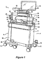
- FIG. 1 illustrates an embodiment of a surgical system 2 according to some embodiments of the present disclosure.
- a three-dimensional (“3D") image scan may be taken of a planned surgical area of a patient using, e.g., the C-Arm imaging device 104 of Fig. 10 or O-Arm imaging device 106 of Fig. 11 , or from another medical imaging device such as a computed tomography (CT) image or MRI.
- CT computed tomography
- This scan can be taken pre-operatively (e.g. few weeks before procedure, most common) or intra-operatively.
- any known 3D or 2D image scan may be used in accordance with various embodiments of the surgical system 2.
- the image scan is sent to a computer platform in communication with the surgical system 2, such as the computer platform 910 of the surgical system 900 ( Fig. 9 ) which may include the camera tracking system 6, the surgical robot 4 (e.g., robot 2 in Fig. 1 ), imaging devices (e.g., C-Arm 104, O-Arm 106, etc.), and an image database 950 for storing image scans of patients.
- a surgeon reviewing the image scan(s) on a display device of the computer platform 910 ( Fig. 9 ) generates a surgical plan defining a target pose for a surgical tool to be used during a surgical procedure on an anatomical structure of the patient.
- Example surgical tools can include, without limitation, drills, screw drivers, retractors, and implants such as a screws, spacers, interbody fusion devices, plates, rods, etc.
- the surgical plan defining the target plane is planned on the 3D image scan displayed on a display device.
- the term “pose” refers to the position and/or the rotational angle of one object (e.g., dynamic reference array, end effector, surgical tool, anatomical structure, etc.) relative to another object and/or to a defined coordinate system.
- a pose may therefore be defined based on only the multidimensional position of one object relative to another object and/or to a defined coordinate system, only on the multidimensional rotational angles of the object relative to another object and/or to a defined coordinate system, or on a combination of the multidimensional position and the multidimensional rotational angles.
- the term “pose” therefore is used to refer to position, rotational angle, or combination thereof.
- the surgical system 2 of Figure 1 can assist surgeons during medical procedures by, for example, holding tools, aligning tools, using tools, guiding tools, and/or positioning tools for use.
- surgical system 2 includes a surgical robot 4 and a camera tracking system 6.
- the ability to mechanically couple surgical robot 4 and camera tracking system 6 can allow for surgical system 2 to maneuver and move as a single unit, and allow surgical system 2 to have a small footprint in an area, allow easier movement through narrow passages and around turns, and allow storage within a smaller area.
- a surgical procedure may begin with the surgical system 2 moving from medical storage to a medical procedure room.
- the surgical system 2 may be maneuvered through doorways, halls, and elevators to reach a medical procedure room.
- the surgical system 2 may be physically separated into two separate and distinct systems, the surgical robot 4 and the camera tracking system 6.
- Surgical robot 4 may be positioned adjacent the patient at any suitable location to properly assist medical personnel.
- Camera tracking system 6 may be positioned at the base of the patient, at the patient shoulders, or any other location suitable to track the present pose and movement of the pose of tracks portions of the surgical robot 4 and the patient.
- Surgical robot 4 and camera tracking system 6 may be powered by an onboard power source and/or plugged into an external wall outlet.
- Surgical robot 4 may be used to assist a surgeon by holding and/or using tools during a medical procedure. To properly utilize and hold tools, surgical robot 4 may rely on a plurality of motors, computers, and/or actuators to function properly. Illustrated in Figure 1 , robot body 8 may act as the structure in which the plurality of motors, computers, and/or actuators may be secured within surgical robot 4. Robot body 8 may also provide support for robot telescoping support arm 16. The size of robot body 8 may provide a solid platform supporting attached components, and may house, conceal, and protect the plurality of motors, computers, and/or actuators that may operate attached components.
- Robot base 10 may act as a lower support for surgical robot 4.
- robot base 10 may support robot body 8 and may attach robot body 8 to a plurality of powered wheels 12. This attachment to wheels may allow robot body 8 to move in space efficiently.
- Robot base 10 may run the length and width of robot body 8.
- Robot base 10 may be about two inches to about 10 inches tall.
- Robot base 10 may cover, protect, and support powered wheels 12.
- At least one powered wheel 12 may be attached to robot base 10.
- Powered wheels 12 may attach to robot base 10 at any location. Each individual powered wheel 12 may rotate about a vertical axis in any direction.
- a motor may be disposed above, within, or adjacent to powered wheel 12. This motor may allow for surgical system 2 to maneuver into any location and stabilize and/or level surgical system 2.
- a rod, located within or adjacent to powered wheel 12, may be pressed into a surface by the motor.
- the rod not pictured, may be made of any suitable metal to lift surgical system 2.
- the rod may lift powered wheel 10, which may lift surgical system 2, to any height required to level or otherwise fix the orientation of the surgical system 2 in relation to a patient.
- the weight of surgical system 2 supported through small contact areas by the rod on each wheel, prevents surgical system 2 from moving during a medical procedure. This rigid positioning may prevent objects and/or people from moving surgical system 2 by accident.
- Moving surgical system 2 may be facilitated using robot railing 14.
- Robot railing 14 provides a person with the ability to move surgical system 2 without grasping robot body 8. As illustrated in Figure 1 , robot railing 14 may run the length of robot body 8, shorter than robot body 8, and/or may run longer the length of robot body 8. Robot railing 14 may further provide protection to robot body 8, preventing objects and or personnel from touching, hitting, or bumping into robot body 8.
- Robot body 8 may provide support for a Selective Compliance Articulated Robot Arm, hereafter referred to as a "SCARA.”
- a SCARA 24 may be beneficial to use within the surgical system 2 due to the repeatability and compactness of the robotic arm. The compactness of a SCARA may provide additional space within a medical procedure, which may allow medical professionals to perform medical procedures free of excess clutter and confining areas.
- SCARA 24 may comprise robot telescoping support 16, robot support arm 18, and/or robot arm 20.
- Robot telescoping support 16 may be disposed along robot body 8. As illustrated in Figure 1 , robot telescoping support 16 may provide support for the SCARA 24 and display 34. In some embodiments, robot telescoping support 16 may extend and contract in a vertical direction.
- the body of robot telescoping support 16 may be any width and/or height configured to support the stress and weight placed upon it.
- medical personnel may move SCARA 24 through a command submitted by the medical personnel.
- the command may originate from input received on display 34, a tablet, and/or an AR headset (e.g., headset 920 in Fig. 9 ) as will be explained in further detail below.
- the AR headset may eliminate the need for medical personnel to refer to any other display such as the display 34 or a tablet, which enables the SCARA 24 to be configured without the display 34 and/or the tablet.
- the command may be generated by the depression of a switch and/or the depression of a plurality of switches, and/or may be generated based on a hand gesture command and/or voice command that is sensed by the AR headset as will be explained in further detail below.
- an activation assembly 60 may include a switch and/or a plurality of switches.
- the activation assembly 60 may be operable to transmit a move command to the SCARA 24 allowing an operator to manually manipulate the SCARA 24.
- the switch, or plurality of switches When the switch, or plurality of switches, is depressed the medical personnel may have the ability to move SCARA 24 through applied hand movements.
- an operator may control movement of the SCARA 24 through hand gesture commands and/or voice commands that are sensed by the AR headset as will be explained in further detail below.
- the SCARA 24 may lock in place to prevent accidental movement by personnel and/or other objects. By locking in place, the SCARA 24 provides a solid platform through which the end effector 26 can guide a surgical tool during a medical procedure.
- Robot support arm 18 can be connected to robot telescoping support 16 by various mechanisms. In some embodiments, best seen in Figures 1 and 2 , robot support arm 18 rotates in any direction in regard to robot telescoping support 16. Robot support arm 18 may rotate three hundred and sixty degrees around robot telescoping support 16. Robot arm 20 may connect to robot support arm 18 at any suitable location and by various mechanisms that enable rotation in any direction relative to robot support arm 18. In one embodiment, the robot arm 20 can rotate three hundred and sixty degrees relative to the robot support arm 18. This free rotation allows an operator to position robot arm 20 according to a surgical plan.
- the end effector 26 shown in Figures 4 and 5 may attach to robot arm 20 in any suitable location.
- the end effector 26 can be configured to attach to an end effector coupler 22 of the robot arm 20 positioned by the surgical robot 4.
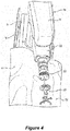
- the example end effector 26 includes a tubular guide that guides movement of an inserted surgical tool relative to an anatomical structure on which a surgical procedure is to be performed.
- a dynamic reference array 52 is attached to the end effector 26.
- Dynamic reference arrays also referred to as "DRAs" herein, are rigid bodies which may be disposed on an anatomical structure (e.g., bone) of a patient, one or more AR headsets being worn by personnel in the operating room, the end effector, the surgical robot, a surgical tool in a navigated surgical procedure.
- the computer platform 910 in combination with the camera tracking system 6 or other 3D localization system are configured to track in real-time the pose (e.g., positions and rotational orientations) of the DRA.
- the DRA can include fiducials, such as the illustrated arrangement of balls. This tracking of 3D coordinates of the DRA can allow the surgical system 2 to determine the pose of the DRA in any multidimensional space in relation to the target anatomical structure of the patient 50 in Figure 5 .
- a light indicator 28 may be positioned on top of the SCARA 24.
- Light indicator 28 may illuminate as any type of light to indicate "conditions" in which surgical system 2 is currently operating.
- the light may be produced by LED bulbs, which may form a ring around light indicator 28.
- Light indicator 28 may comprise a fully permeable material that can let light shine through the entirety of light indicator 28.
- Light indicator 28 may be attached to lower display support 30.
- Lower display support 30, as illustrated in Figure 2 may allow an operator to maneuver display 34 to any suitable location.
- Lower display support 30 may attach to light indicator 28 by any suitable mechanism.
- lower display support 30 may rotate about light indicator 28 or be rigidly attached thereto.
- Upper display support 32 may attach to lower display support 30 by any suitable mechanism.
- a tablet may be used in conjunction with display 34 and/or without display 34.
- the tablet may be disposed on upper display support 32, in place of display 34, and may be removable from upper display support 32 during a medical operation.
- the tablet may communicate with display 34.
- the tablet may be able to connect to surgical robot 4 by any suitable wireless and/or wired connection.
- the tablet may be able to program and/or control surgical system 2 during a medical operation. When controlling surgical system 2 with the tablet, all input and output commands may be duplicated on display 34.
- the use of a tablet may allow an operator to manipulate surgical robot 4 without having to move around patient 50 and/or to surgical robot 4.
- a surgeon and/or other personnel can wear AR headsets that may be used in conjunction with display 34 and/or a tablet or the AR head(s) may eliminate the need for use of the display 34 and/or tablet.
- camera tracking system 6 works in conjunction with surgical robot 4 through wired or wireless communication networks.
- camera tracking system 6 can include some similar components to the surgical robot 4.
- camera body 36 may provide the functionality found in robot body 8.
- Robot body 8 may provide the structure upon which camera 46 is mounted. The structure within robot body 8 may also provide support for the electronics, communication devices, and power supplies used to operate camera tracking system 6.
- Camera body 36 may be made of the same material as robot body 8.
- Camera tracking system 6 may communicate directly to an AR headset, tablet and/or display 34 by a wireless and/or wired network to enable the AR headset, tablet and/or display 34 to control the functions of camera tracking system 6.
- Camera body 36 is supported by camera base 38.
- Camera base 38 may function as robot base 10.
- camera base 38 may be wider than robot base 10.
- the width of camera base 38 may allow for camera tracking system 6 to connect with surgical robot 4.
- the width of camera base 38 may be large enough to fit outside robot base 10.
- the additional width of camera base 38 may allow surgical system 2 additional maneuverability and support for surgical system 2.
- a plurality of powered wheels 12 may attach to camera base 38.
- Powered wheel 12 may allow camera tracking system 6 to stabilize and level or set fixed orientation in regards to patient 50, similar to the operation of robot base 10 and powered wheels 12.
- This stabilization may prevent camera tracking system 6 from moving during a medical procedure and may keep camera 46 from losing track of a DRA connected to an AR headset and/or the surgical robot 4, and/or losing track of one or more DRAs 52 connected to an anatomical structure 54 and/or tool 58 within a designated area 56 as shown in Figures 3A and 5 .
- This stability and maintenance of tracking enhances the ability of surgical robot 4 to operate effectively with camera tracking system 6.
- the wide camera base 38 may provide additional support to camera tracking system 6.
- a wide camera base 38 may prevent camera tracking system 6 from tipping over when camera 46 is disposed over a patient, as illustrated in Figures 3A and 5 .
- Camera telescoping support 40 may support camera 46. In some embodiments, telescoping support 40 moves camera 46 higher or lower in the vertical direction.
- Camera handle 48 may be attached to camera telescoping support 40 at any suitable location and configured to allow an operator to move camera tracking system 6 into a planned position before a medical operation. In some embodiments, camera handle 48 is used to lower and raise camera telescoping support 40. Camera handle 48 may perform the raising and lowering of camera telescoping support 40 through the depression of a button, switch, lever, and/or any combination thereof.
- Lower camera support arm 42 may attach to camera telescoping support 40 at any suitable location, in embodiments, as illustrated in Figure 1 , lower camera support arm 42 may rotate three hundred and sixty degrees around telescoping support 40. This free rotation may allow an operator to position camera 46 in any suitable location.
- Lower camera support arm 42 may connect to telescoping support 40 by any suitable mechanism.
- Lower camera support arm 42 may be used to provide support for camera 46.
- Camera 46 may be attached to lower camera support arm 42 by any suitable mechanism.
- Camera 46 may pivot in any direction at the attachment area between camera 46 and lower camera support arm 42.
- a curved rail 44 may be disposed on lower camera support arm 42.
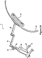
- Curved rail 44 may be disposed at any suitable location on lower camera support arm 42. As illustrated in Figure 3A , curved rail 44 may attach to lower camera support arm 42 by any suitable mechanism. Curved rail 44 may be of any suitable shape, a suitable shape may be a crescent, circular, oval, elliptical, and/or any combination thereof. Camera 46 may be moveably disposed along curved rail 44. Camera 46 may attach to curved rail 44 by, for example, rollers, brackets, braces, motors, and/or any combination thereof. Motors and rollers, not illustrated, may be used to move camera 46 along curved rail 44.
- the motors may responsively move camera 46 along curved rail 44. This motorized movement may allow camera 46 to move to a new position that is no longer obstructed by the object without moving camera tracking system 6. While camera 46 is obstructed from viewing one or more tracked DRAs, camera tracking system 6 may send a stop signal to an surgical robot 4, AR headset, display 34, and/or a tablet. The stop signal may prevent SCARA 24 from moving until camera 46 has reacquired tracked DRAs 52 and/or can warn an operator wearing the AR headset and/or viewing the display 34 and/or the tablet. This SCARA 24 can be configured to respond to receipt of a stop signal by stopping further movement of the base and/or end effector coupler 22 until the camera tracking system can resume tracking of DRAs.
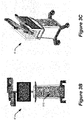
- Figures 3B and 3C illustrate a front view and isometric view of another camera camera tracking system 6' which may be used with the surgical system of Figure 1 or may be used independent of a surgical robot.
- the camera tracking system 6' may be used for providing navigated surgery without use of robotic guidance.
- One of the differences between the camera tracking system 6' of Figures 3B and 3C and the camera tracking system 6 of Figure 3A is that the camera tracking system 6' of Figures 3B and 3C includes a housing that transports the computer platform 910.
- the computer platform 910 can be configured to perform camera tracking operations to track DRAs, perform navigated surgery operations that provide surgical navigation information to a display device, e.g., AR headset and/or other display device, and perform other computational operations disclosed herein.
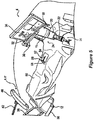
- Figure 6 illustrates a block diagram view of the components of the surgical system of Figure 5 used for the medical operation.
- the navigation camera 46 has a navigation field-of-view 600 in which the pose (e.g., position and orientation) of the reference array 602 attached to the patient, the reference array 604 attached to the surgical instrument, and the robot arm 20 are tracked.
- the navigation camera 46 may be part of the camera tracking system 6' of Figures 3B and 3C , which includes the computer platform 910 configured to perform the operations described below.
- the reference arrays enable tracking by reflecting light in known patterns, which are decoded to determine their respective poses by the tracking subsystem of the surgical robot 4.
- the navigation camera 46 may block (for example, by a medical personnel, instrument, etc.), further navigation of the surgical instrument may not be able to be performed and a responsive notification may temporarily halt further movement of the robot arm 20 and surgical robot 4, display a warning on the display 34, and/or provide an audible warning to medical personnel.
- the display 34 is accessible to the surgeon 610 and assistant 612 but viewing requires a head to be turned away from the patient and for eye focus to be changed to a different distance and location.
- the navigation software may be controlled by a tech personnel 614 based on vocal instructions from the surgeon.
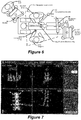
- Figure 7 illustrates various display screens that may be displayed on the display 34 of Figures 5 and 6 by the surgical robot 4 when using a navigation function of the surgical system 2.
- the display screens can include, without limitation, patient radiographs with overlaid graphical representations of models of instruments that are positioned in the display screens relative to the anatomical structure based on a developed surgical plan and/or based on poses of tracked reference arrays, various user selectable menus for controlling different stages of the surgical procedure and dimension parameters of a virtually projected implant (e.g. length, width, and/or diameter).
- processing components e.g., computer platform 910 and associated software described below are provided that enable pre-operatively planning of a surgical procedure, e.g., implant placement, and electronic transfer of the plan to computer platform 910 to provide navigation information to one or more users during the planned surgical procedure.
- a surgical procedure e.g., implant placement
- electronic transfer of the plan to computer platform 910 to provide navigation information to one or more users during the planned surgical procedure.
- various processing components e.g., computer platform 910 and associated software described below are provided that enable pre-operatively planning of a surgical procedure, e.g., implant placement, and electronic transfer of the plan to the surgical robot 4.
- the surgical robot 4 uses the plan to guide the robot arm 20 and connected end effector 26 to provide a target pose for a surgical tool relative to a patient anatomical structure for a step of the planned surgical procedure.
- Various embodiments below are directed to using one or more AR headsets that can be worn by the surgeon 610, the assistant 612, and/or other medical personnel to provide an improved user interface for receiving information from and/or providing control commands to the surgical robot, the camera tracking system 6/6', and/or other medical equipment in the operating room.
- FIG. 8 illustrates a block diagram of some electrical components of the surgical robot 4 according to some embodiments of the present disclosure.
- a load cell (not shown) may be configured to track force applied to end effector coupler 22.
- the load cell may communicate with a plurality of motors 850, 851, 852, 853, and/or 854.
- Controller 846 may take the force information from load cell and process it with a switch algorithm. The switch algorithm is used by the controller 846 to control a motor driver 842.
- the motor driver 842 controls operation of one or more of the motors 850, 851, 852, 853, and 854.
- Motor driver 842 may direct a specific motor to produce, for example, an equal amount of force measured by load cell through the motor.
- the force produced may come from a plurality of motors, e.g., 850-854, as directed by controller 846.
- motor driver 842 may receive input from controller 846.
- Controller 846 may receive information from load cell as to the direction of force sensed by load cell. Controller 846 may process this information using a motion controller algorithm. The algorithm may be used to provide information to specific motor drivers 842. To replicate the direction of force, controller 846 may activate and/or deactivate certain motor drivers 842.
- Controller 846 may control one or more motors, e.g. one or more of 850-854, to induce motion of end effector 26 in the direction of force sensed by load cell.
- This force-controlled motion may allow an operator to move SCARA 24 and end effector 26 effortlessly and/or with very little resistance. Movement of end effector 26 can be performed to position end effector 26 in any suitable pose (i.e., location and angular orientation relative to defined three-dimensional (3D) orthogonal reference axes) for use by medical personnel.
- Activation assembly 60 may form of a bracelet that wraps around end effector coupler 22.
- the activation assembly 60 may be located on any part of SCARA 24, any part of end effector coupler 22, may be worn by medical personnel (and communicate wirelessly), and/or any combination thereof.
- Activation assembly 60 may comprise of a primary button and a secondary button.
- Depressing primary button may allow an operator to move SCARA 24 and end effector coupler 22.
- SCARA 24 and end effector coupler 22 may not move until an operator programs surgical robot 4 to move SCARA 24 and end effector coupler 22, or is moved using primary button.
- it may require the depression of at least two non-adjacent primary activation switches before SCARA 24 and end effector coupler 22 will respond to operator commands. Depression of at least two primary activation switches may prevent the accidental movement of SCARA 24 and end effector coupler 22 during a medical procedure.
- load cell may measure the force magnitude and/or direction exerted upon end effector coupler 22 by an operator, i.e. medical personnel. This information may be transferred to one or more motors, e.g. one or more of 850-854, within SCARA 24 that may be used to move SCARA 24 and end effector coupler 22. Information as to the magnitude and direction of force measured by load cell may cause the one or more motors, e.g. one or more of 850-854, to move SCARA 24 and end effector coupler 22 in the same direction as sensed by the load cell.
- motors e.g. one or more of 850-854
- This force-controlled movement may allow the operator to move SCARA 24 and end effector coupler 22 easily and without large amounts of exertion due to the motors moving SCARA 24 and end effector coupler 22 at the same time the operator is moving SCARA 24 and end effector coupler 22.
- a secondary button may be used by an operator as a "selection" device.
- surgical robot 4 may notify medical personnel to certain conditions by the AR headset(s) 920, display 34 and/or light indicator 28.
- the AR headset(s) 920 are each configured to display images on a see-through display screen to form an augmented reality image that is overlaid on real-world objects viewable through the see-through display screen.
- Medical personnel may be prompted by surgical robot 4 to select a function, mode, and/or asses the condition of surgical system 2. Depressing secondary button a single time may activate certain functions, modes, and/or acknowledge information communicated to medical personnel through the AR headset(s) 920, display 34 and/or light indicator 28. Additionally, depressing the secondary button multiple times in rapid succession may activate additional functions, modes, and/or select information communicated to medical personnel through the AR headset(s) 920, display 34 and/or light indicator 28.
- electrical components of the surgical robot 4 include platform subsystem 802, computer subsystem 820, motion control subsystem 840, and tracking subsystem 830.
- Platform subsystem 802 includes battery 806, power distribution module 804, connector panel 808, and charging station 810.
- Computer subsystem 820 includes computer 822, display 824, and speaker 826.
- Motion control subsystem 840 includes driver circuit 842, motors 850, 851, 852, 853, 854, stabilizers 855, 856, 857, 858, end effector connector 844, and controller 846.
- Tracking subsystem 830 includes position sensor 832 and camera converter 834.
- Surgical robot 4 may also include a removable foot pedal 880 and removable tablet computer 890.
- Input power is supplied to surgical robot 4 via a power source which may be provided to power distribution module 804.
- Power distribution module 804 receives input power and is configured to generate different power supply voltages that are provided to other modules, components, and subsystems of surgical robot 4.
- Power distribution module 804 may be configured to provide different voltage supplies to connector panel 808, which may be provided to other components such as computer 822, display 824, speaker 826, driver 842 to, for example, power motors 850-854 and end effector coupler 844, and provided to camera converter 834 and other components for surgical robot 4.
- Power distribution module 804 may also be connected to battery 806, which serves as temporary power source in the event that power distribution module 804 does not receive power from an input power. At other times, power distribution module 804 may serve to charge battery 806.
- Connector panel 808 may serve to connect different devices and components to surgical robot 4 and/or associated components and modules.
- Connector panel 808 may contain one or more ports that receive lines or connections from different components.
- connector panel 808 may have a ground terminal port that may ground surgical robot 4 to other equipment, a port to connect foot pedal 880, a port to connect to tracking subsystem 830, which may include position sensor 832, camera converter 834, and DRA tracking cameras 870.
- Connector panel 808 may also include other ports to allow USB, Ethernet, HDMI communications to other components, such as computer 822.
- the connector panel 808 can include a wired and/or wireless interface for operatively connecting one or more AR headsets 920 to the tracking subsystem 830 and/or the computer subsystem 820.
- Control panel 816 may provide various buttons or indicators that control operation of surgical robot 4 and/or provide information from surgical robot 4 for observation by an operator.
- control panel 816 may include buttons to power on or off surgical robot 4, lift or lower vertical column 16, and lift or lower stabilizers 855-858 that may be designed to engage casters 12 to lock surgical robot 4 from physically moving.
- Other buttons may stop surgical robot 4 in the event of an emergency, which may remove all motor power and apply mechanical brakes to stop all motion from occurring.
- Control panel 816 may also have indicators notifying the operator of certain system conditions such as a line power indicator or status of charge for battery 806.
- one or more AR headsets 920 may communicate, e.g. via the connector panel 808, to control operation of the surgical robot 4 and/or to received and display information generated by surgical robot 4 for observation by persons wearing the AR headsets 920.
- Computer 822 of computer subsystem 820 includes an operating system and software to operate assigned functions of surgical robot 4.
- Computer 822 may receive and process information from other components (for example, tracking subsystem 830, platform subsystem 802, and/or motion control subsystem 840) in order to display information to the operator.
- computer subsystem 820 may provide output through the speaker 826 for the operator.
- the speaker may be part of the surgical robot, part of an AR headset 920, or within another component of the surgical system 2.
- the display 824 may correspond to the display 34 shown in Figures 1 and 2 .
- Tracking subsystem 830 may include position sensor 832 and camera converter 834. Tracking subsystem 830 may correspond to the camera tracking system 6 of Figure 3 .
- the DRA tracking cameras 870 operate with the position sensor 832 to determine the pose of DRAs 52. This tracking may be conducted in a manner consistent with the present disclosure including the use of infrared or visible light technology that tracks the location of active or passive elements of DRAs 52, such as LEDs or reflective markers, respectively.
- the tracking subsystem 830 and the computer subsystem 820 can be included in the computer platform 910, which can be transported by the camera tracking system 6' of Figures 3A and 3B .
- the tracking subsystem 830 can be configured to determine the poses, e.g., location and angular orientation of the tracked DRAs.
- the computer platform 910 can also include a navigation controller that is configured to use the determined poses to provide navigation information to users that guides their movement of tracked tools relative to position-registered patient images and/or tracked anatomical structures during a planned surgical procedure.
- the computer platform 910 can display information on the display of Figures 3B and 3C and/or to one or more AR headsets 920.
- the computer platform 910 when used with a surgical robot, can be configured to communicate with the computer subsystem 820 and other subsystems of Figure 8 to control movement of the end effector 26.
- the computer platform 910 can generate a graphical representation of a patient's anatomical structure, surgical tool, user's hand, etc. with a displayed size, shape, color, and/or pose that is controlled based on the determined pose(s) of one or more the tracked DRAs, and which the graphical representation that is displayed can be dynamically modified to track changes in the determined poses over time.
- Motion control subsystem 840 may be configured to physically move vertical column 16, upper arm 18, lower arm 20, or rotate end effector coupler 22.
- the physical movement may be conducted through the use of one or more motors 850-854.
- motor 850 may be configured to vertically lift or lower vertical column 16.
- Motor 851 may be configured to laterally move upper arm 18 around a point of engagement with vertical column 16 as shown in Figure 2 .
- Motor 852 may be configured to laterally move lower arm 20 around a point of engagement with upper arm 18 as shown in Figure 2 .
- Motors 853 and 854 may be configured to move end effector coupler 22 to provide translational movement and rotation along in about three-dimensional axes.
- the computer platform 910 shown in Figure 9 can provide control input to the controller 846 that guides movement of the end effector coupler 22 to position a passive end effector, which is connected thereto, with a planned pose (i.e., location and angular orientation relative to defined 3D orthogonal reference axes) relative to an anatomical structure that is to be operated on during a planned surgical procedure.
- Motion control subsystem 840 may be configured to measure position of the end effector coupler 22 and/or the end effector 26 using integrated position sensors (e.g. encoders).
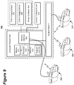
- Figure 9 illustrates a block diagram of components of a surgical system that includes imaging devices (e.g., C-Arm 104, O-Arm 106, etc.) connected to a computer platform 910 which can be operationally connected to a camera tracking system 6 ( Fig. 3A ) or 6' ( Figs. 3B,3C ) and/or to surgical robot 4 according to some embodiments of the present disclosure.
- imaging devices e.g., C-Arm 104, O-Arm 106, etc.
- a computer platform 910 which can be operationally connected to a camera tracking system 6 ( Fig. 3A ) or 6' ( Figs. 3B,3C ) and/or to surgical robot 4 according to some embodiments of the present disclosure.
- a camera tracking system 6 Fig. 3A
- 6' Figs. 3B,3C
- the computer platform 910 includes a display 912, at least one processor circuit 914 (also referred to as a processor for brevity), at least one memory circuit 916 (also referred to as a memory for brevity) containing computer readable program code 918, and at least one network interface 902 (also referred to as a network interface for brevity).
- the display 912 may be part of an AR headset 920 in accordance with some embodiments of the present disclosure.
- the network interface 902 can be configured to connect to a C-Arm imaging device 104 in Figure 10 , an O-Arm imaging device 106 in Figure 11 , another medical imaging device, an image database 950 containing patient medical images, components of the surgical robot 4, and/or other electronic equipment.
- the display 912 When used with a surgical robot 4, the display 912 may correspond to the display 34 of Figure 2 and/or the tablet 890 of Figure 8 and/or the AR headset 920 that is operatively connected to the surgical robot 4, the network interface 902 may correspond to the platform network interface 812 of Figure 8 , and the processor 914 may correspond to the computer 822 of Figure 8 .
- the network interface 902 of the AR headset 920 may be configured to communicate through a wired network, e.g., thin wire ethernet, and/or through wireless RF transceiver link according to one or more wireless communication protocols, e.g., WLAN, 3GPP 4G and/or 5G (New Radio) cellular communication standards, etc.
- wireless communication protocols e.g., WLAN, 3GPP 4G and/or 5G (New Radio) cellular communication standards, etc.
- the processor 914 may include one or more data processing circuits, such as a general purpose and/or special purpose processor, e.g., microprocessor and/or digital signal processor.
- the processor 914 is configured to execute the computer readable program code 918 in the memory 916 to perform operations, which may include some or all of the operations described herein as being performed for surgery planning, navigated surgery, and/or robotic surgery.
- the computer platform 910 can be configured to provide surgery planning functionality.
- the processor 914 can operate to display on the display device 912 and/or on the AR headset 920 an image of an anatomical structure, e.g., vertebra, that is received from one of the imaging devices 104 and 106 and/or from the image database 950 through the network interface 920.
- the processor 914 receives an operator's definition of where the anatomical structure shown in one or more images is to have a surgical procedure, e.g., screw placement, such as by the operator touch selecting locations on the display 912 for planned procedures or using a mouse-based cursor to define locations for planned procedures.
- the AR headset can be configured to sense in gesture-based commands formed by the wearer and/or sense voice based commands spoken by the wearer, which can be used to control selection among menu items and/or control how objects are displayed on the AR headset 920 as will be explained in further detail below.
- the computer platform 910 can be configured to enable anatomy measurement, which can be particularly useful for knee surgery, like measurement of various angles determining center of hip, center of angles, natural landmarks (e.g. transepicondylar line, Whitesides line, posterior condylar line), etc. Some measurements can be automatic while some others can involve human input or assistance.
- the computer platform 910 may be configured to allow an operator to input a choice of the correct implant for a patient, including choice of size and alignment.
- the computer platform 910 may be configured to perform automatic or semi-automatic (involving human input) segmentation (image processing) for CT images or other medical images.
- the surgical plan for a patient may be stored in a cloud-based server, which may correspond to database 950, for retrieval by the surgical robot 4.
- a surgeon may choose which cut to make (e.g. posterior femur, proximal tibia etc.) using a computer screen (e.g. touchscreen) or augmented reality interaction (e.g., hand gesture based commands and/or voice based commands) via, e.g., the AR headset 920.
- the computer platform 910 can generate navigation information which provides visual guidance to the surgeon for performing the surgical procedure.
- the computer platform 910 can provide guidance that allows the surgical robot 4 to automatically move the end effector 26 to a target pose so that the surgical tool is aligned with a target location to perform the surgical procedure on an anatomical structure.
- the surgical system 900 can use two DRAs to track patient anatomy position, such as one connected to patient tibia and one connected to patient femur.
- the system 900 may use standard navigated instruments for the registration and checks (e.g. a pointer similar to the one used in Globus ExcelsiusGPS system for spine surgery).
- a particularly challenging task in navigated surgery is how to plan the position of an implant in spine, knee, and other anatomical structures where surgeons struggle to perform the task on a computer screen which is a 2D representation of the 3D anatomical structure.
- the system 900 could address this problem by using the AR headset 920 to display a three-dimensional (3D) computer generated representations of the anatomical structure and a candidate implant device.
- the computer generated representations are scaled and posed relative to each other on the display screen under guidance of the computer platform 910 and which can be manipulated by a surgeon while viewed through the AR headset 920.
- a surgeon may, for example, manipulate the displayed computer-generated representations of the anatomical structure, the implant, a surgical tool, etc., using hand gesture based commands and/or voice based commands that are sensed by the AR headset 920.
- a surgeon can view a displayed virtual handle on a virtual implant, and can manipulate (e.g., grab and move) the virtual handle to move the virtual implant to a desired pose and adjust a planned implant placement relative to a graphical representation of an anatomical structure.
- the computer platform 910 could display navigation information through the AR headset 920 that facilitates the surgeon's ability to more accurately follow the surgical plan to insert the implant and/or to perform another surgical procedure on the anatomical structure.
- the progress of bone removal e.g., depth of cut
- Other features that may be displayed through the AR headset 920 can include, without limitation, gap or ligament balance along a range of joint motion, contact line on the implant along the range of joint motion, ligament tension and/or laxity through color or other graphical renderings, etc.
- the computer platform 910 can allow planning for use of standard surgical tools and/or implants, e.g., posterior stabilized implants and cruciate retaining implants, cemented and cementless implants, revision systems for surgeries related to, for example, total or partial knee and/or hip replacement and/or trauma.
- standard surgical tools and/or implants e.g., posterior stabilized implants and cruciate retaining implants, cemented and cementless implants, revision systems for surgeries related to, for example, total or partial knee and/or hip replacement and/or trauma.
- An automated imaging system can be used in conjunction with the computer platform 910 to acquire pre-operative, intra-operative, post-operative, and/or real-time image data of an anatomical structure.
- Example automated imaging systems are illustrated in Figures 10 and 11 .
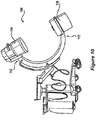
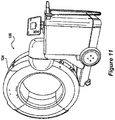
- the automated imaging system is a C-arm 104 ( Fig. 10 ) imaging device or an O-arm® 106 ( Fig. 11 ).
- O-arm® is copyrighted by Medtronic Navigation, Inc. having a place of business in Louisville, Colo., USA) It may be desirable to take x-rays of a patient from a number of different positions, without the need for frequent manual repositioning of the patient which may be required in an x-ray system.
- C-arm 104 x-ray diagnostic equipment may solve the problems of frequent manual repositioning and may be well known in the medical art of surgical and other interventional procedures.
- a C-arm includes an elongated C-shaped member terminating in opposing distal ends 112 of the "C" shape.
- C-shaped member is attached to an x-ray source 114 and an image receptor 116.
- the space within C-arm 104 of the arm provides room for the physician to attend to the patient substantially free of interference from the x-ray support structure.
- the C-arm is mounted to enable rotational movement of the arm in two degrees of freedom, (i.e. about two perpendicular axes in a spherical motion).
- C-arm is slidably mounted to an x-ray support structure, which allows orbiting rotational movement of the C-arm about its center of curvature, which may permit selective orientation of x-ray source 114 and image receptor 116 vertically and/or horizontally.
- the C-arm may also be laterally rotatable, (i.e. in a perpendicular direction relative to the orbiting direction to enable selectively adjustable positioning of x-ray source 114 and image receptor 116 relative to both the width and length of the patient).
- Spherically rotational aspects of the C-arm apparatus allow physicians to take x-rays of the patient at an optimal angle as determined with respect to the particular anatomical condition being imaged.
- the O-arm® 106 illustrated in Figure 11 includes a gantry housing 124 which may enclose an image capturing portion, not illustrated.
- the image capturing portion includes an x-ray source and/or emission portion and an x-ray receiving and/or image receiving portion, which may be disposed about one hundred and eighty degrees from each other and mounted on a rotor (not illustrated) relative to a track of the image capturing portion.
- the image capturing portion may be operable to rotate three hundred and sixty degrees during image acquisition.
- the image capturing portion may rotate around a central point and/or axis, allowing image data of the patient to be acquired from multiple directions or in multiple planes.
- the O-arm® 106 with the gantry housing 124 has a central opening for positioning around an object to be imaged, a source of radiation that is rotatable around the interior of gantry housing 124, which may be adapted to project radiation from a plurality of different projection angles.
- a detector system is adapted to detect the radiation at each projection angle to acquire object images from multiple projection planes in a quasi-simultaneous manner.
- the gantry may be attached to a support structure O-arm® support structure, such as a wheeled mobile cart with wheels, in a cantilevered fashion.
- a positioning unit translates and/or tilts the gantry to a planned position and orientation, preferably under control of a computerized motion control system.
- the gantry may include a source and detector disposed opposite one another on the gantry.
- the source and detector may be secured to a motorized rotor, which may rotate the source and detector around the interior of the gantry in coordination with one another.
- the source may be pulsed at multiple positions and orientations over a partial and/or full three hundred and sixty degree rotation for multi-planar imaging of a targeted object located inside the gantry.
- the gantry may further comprise a rail and bearing system for guiding the rotor as it rotates, which may carry the source and detector.
- Both and/or either O-arm® 106 and C-arm 104 may be used as automated imaging system to scan a patient and send information to the surgical system 2.
- Images captured by an imaging system can be displayed on the AR headset 920 and/or another display device of the computer platform 910, the surgical robot 4, and/or another component of the surgical system 900.
- the AR headset 920 may be connected to one or more of the imaging devices 104 and/or 106 and/or to the image database 950, e.g., via the computer platform 910, to display images therefrom.
- a user may provide control inputs through the AR headset 920, e.g., gesture and/or voice based commands, to control operation of one or more of the imaging devices 104 and/or 106 and/or the image database 950.
- Figure 12 illustrates a block diagram view of the components of a surgical system that include a pair of AR headsets 1200 and 1210 (head-mounted displays HMD1 and HMD2), which may correspond to the AR headset 920 shown in Figure 13 and operate in accordance with some embodiments of the present disclosure.
- a pair of AR headsets 1200 and 1210 head-mounted displays HMD1 and HMD2
- HMD1 and HMD2 head-mounted displays
- the assistant 612 and surgeon 610 are both wearing the AR headsets 1210 and 1210, respectively. It is optional for the assistant 612 to wear the AR headset 1210.
- the AR headsets 1200 and 1210 are configured to provide an interactive environment through which the wearers can view and interact with information related to a surgical procedure as will be described further below. This interactive AR based environment may eliminate a need for the tech 614 to be present in the operating room and may eliminate a need for use of the display 34 shown in Figure 6 .
- Each AR headset 1200 and 1210 can include one or more cameras that are be configured to provide an additional source of tracking of DRAs or other reference arrays attached to instruments, an anatomical structure, the end effector 26, and/or other equipment.
- AR headset 1200 has a field-of-view (FOV) 1202 for tracking DRAs and other objects
- AR headset 1210 has a FOV 1212 partially overlapping FOV 1202 for tracking DRAs and other objects
- the navigation camera 46 has another FOV 600 partially overlapping FOVs 1202 and 1212 for tracking DRAs and other objects.
- FOV field-of-view
- the tracking subsystem 830 and/or navigation controller 828 can continue to track the object seamlessly without loss of navigation. Additionally, if there is partial occlusion of the DRA from the perspective of one camera, but the entire DRA is visible via multiple camera sources, the tracking inputs of the cameras can be merged to continue navigation of the DRA.
- One of the AR headsets and/or the navigation camera 46 may view and track the DRA on another one of the AR headsets to enable the computer platform 910 ( Figs. 9 and 14 ), the tracking subsystem 830, and/or another computing component to determine the pose of the AR headset.
- the AR headsets 1200 and 1210 can be operatively connected to view video, pictures, and/or other information received from and/or to provide commands that control various equipment in the surgical room, including but not limited to neuromonitoring, microscopes, video cameras, and anesthesia systems. Data from the various equipment may be processed and displayed within the headset, for example the display of patient vitals or the microscope feed.
- FIG. 13 illustrates an AR headset 920 which is configured in accordance with some embodiments of the present disclosure.
- the AR headset includes a headband 1306 configured to secure the AR headset to a wearer's head, and includes a display screen 1302 and an electronic component enclosure 1304 supported by the headband 1306.
- the display screen 1302 may be a see-through LCD display device or a semi-reflective lens that reflects images projected by a display device toward the wearer's eyes.
- Figure 14 illustrates electrical components of the AR headset 920 that can be operatively connected to the computer platform 910, to one or more of the imaging devices, such as the C-arm imaging device 104, the O-arm imaging device 106, and/or the image database 950, and/or to the surgical robot 800 in accordance with some embodiments of the present disclosure.
- the imaging devices such as the C-arm imaging device 104, the O-arm imaging device 106, and/or the image database 950, and/or to the surgical robot 800 in accordance with some embodiments of the present disclosure.
- the AR headset 920 provides an improved human interface for performing navigated surgical procedures.
- the AR headset 920 can be configured to provide functionalities, e.g., via the computer platform 910, that include without limitation any one or more of: identification of hand gesture based commands and/or voice based commands, display AR graphical objects as an overlay which may be anchored to particular real-world objects viewed through the display screen 1450 and associated optics, display images in various defined display regions, display video feeds from cameras mounted to one or more AR headsets 920 and other cameras, and control surgical light (in-built or otherwise connectable), etc.
- functionalities e.g., via the computer platform 910, that include without limitation any one or more of: identification of hand gesture based commands and/or voice based commands, display AR graphical objects as an overlay which may be anchored to particular real-world objects viewed through the display screen 1450 and associated optics, display images in various defined display regions, display video feeds from cameras mounted to one or more AR headsets 920 and other cameras, and control surgical light (in-
- Electrical components of the AR headset 920 can include one or more cameras 1440, a microphone 1442, a gesture sensor 1444, a pose sensor (e.g., inertial measurement unit (IMU)) 1446, a display module 1448, and a display screen 1450 configured to display images for viewing by the wearer and to allow at least some ambient light to pass therethrough for viewing by the wearer.
- the one or more cameras 1440 may be configured operate as the gesture sensor 1444 by enabling identification of user hand gestures performed within the field of view of the camera(s) 1440.
- the gesture sensor 1444 may be a proximity sensor and/or a touch sensor that senses hand gestures performed proximately to the gesture sensor 1444 and/or senses physical contact, e.g.
- the pose sensor 1446 may include a multiaxis accelerometer, a tilt sensor, and/or another sensor that can sense rotation and/or acceleration of the AR headset 920 along one or more defined coordinate axes. Some or all of these electrical components may be contained in the component enclosure 1304 or may be contained in another enclosure configured to be worn elsewhere, such as on the hip or shoulder.
- the surgical system 2 includes a tracking system, e.g., 6/6' in Fig. 12 and tracking subsystem 830 in Fig. 8 and/or computer platform 910, and a surgical robot 4.
- the tracking system is configured to determine a pose of an anatomical structure and a pose of an end effector and/or a surgical tool.
- the surgical robot 4 includes one or more navigation controllers e.g., 828 in Fig. 14 , that are configured to determine a target pose for the surgical tool based on a surgical plan, e.g., from a surgical planning function performed by the computer platform 910 of Fig.
- the one or more navigation controllers are further configured to generate steering information based on the target pose for the surgical tool, the pose of the anatomical structure, and the pose of the surgical tool and/or the end effector, the steering information indicating where the surgical tool and/or the end effector need to be moved under control of the at least one motor.
- the electrical components of AR headset 920 can be operatively connected to the electrical components of the computer platform 910 through a wired/wireless interface 1452.
- the electrical components of AR headset 920 may be operatively connected, e.g., through the computer platform 910 or directly, to various imaging devices, e.g., the C-arm imaging device 104, the I/O-arm imaging device 106, the image database 950, and/or to other medical equipment through the wired/wireless interface 1452.
- the surgical system 2 further includes at least one AR headset controller 1430 (also referred to as "AR headset controller” for brevity) that is may reside in the AR headset 920 and/or in the computer platform 910.
- the AR headset controller 1430 is configured to receive navigation information from the navigation controller 828 which provides guidance to the user during the surgical procedure on an anatomical structure, and is configured to generate an AR image based on the navigation information for display on the see-through display screen 1450.
- the see-through display screen (also referred to as "display screen") 1450 is configured to display objects through an optical system in a manner such that when the wearer looks therethrough, the object appears to be displayed in the real world.
- the optical system can be positioned by the headband 1306 directly placed in front of the wearer's eyes.
- Various functionality is provided by software executed by the AR headset controller 1430 which can reside in the AR headset 920 and/or in an external component connected via wired cables and/or wireless communication links.
- the AR headset controller 1430 can be within a housing that is configured to be worn on a user's head or elsewhere on the user's body while viewing the display screen 1450 or may be remotely located from the user viewing the display screen while being communicatively connected to the display screen 1450.
- the AR headset controller 1430 can be configured to operationally process signaling from the cameras 1440, the microphone 142, and/or the pose sensor 1446, and is connected to display AR images on the display screen 1450, e.g., via the display module 1448.
- the AR headset controller 1430 illustrated as a block within the AR headset 920 is to be understood as being operationally connected to other illustrated components of the AR headset 920 but not necessarily residing within a common housing or being transportable by a user.
- the AR headset controller 1430 may reside within the computer platform 910 which, in turn, may reside with the housing of the computer tracking system 6' shown in Figures 3B and 3C .
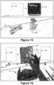
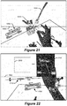
- Figures 15 - 25 illustrate example views provided to the wearer through the display screen 1450 of the AR headset 920 in accordance with some embodiments of the present disclosure.
- One potential drawback of using an AR headset in an operating room is the potential for bright ambient lighting to "wash-out” or reduce the contrast of displayed objects.
- These potential drawbacks can be reduced or eliminated by some embodiments described below where the display screen 1450 is configured to have horizontal bands of differing light transmissivity (opaqueness) and/or where attachable components of varying size adjust opacity of the user's view through the display screen 1450.
- These darkened band(s) of the optical system can function to increase the contrast of displayed objects to, for example, enable a surgeon to more accurately view medical radiographs.
- the see-through display screen 1450 is configured with at least two laterally extending bands, where an upper one of the at least two laterally extending bands has a lower light transmissivity, e.g., darker, (more opaqueness) than a lower one of the at least two laterally extending bands which constrain incident ambient light passing therethrough for viewing by the user.
- the at least one AR headset controller 1430 can be configured to display two dimensional images in the upper one of the at least two laterally extending bands and to display a three dimensional model of the anatomical structure provided by the at least one navigation controller 1430.
- the AR headset user interface further enables sterile software control and salient display of information features that address limitations of current navigation technology. Additionally, as described below, operational functionality is provided that enables wearers to virtually interact with navigation elements using hands, surgical instruments, and/or other objects.
- the AR headset operations can display both 2D images and 3D models in the different bands.
- the 2D images may preferably be displayed in a more opaque band (upper band of the display screen optics) and the 3D model may be more preferably displayed in the more transparent band, otherwise known as the environmental region (bottom band of the display screen optics). Below this band where the display screen optics end, the wearer has an unobstructed view of the patient.
- the separate bands are fluidic. It is possible that the 3D content moves to the opaque band depending on the position of the headset relative to the content, and 2D content can be placed in the transparent band and stabilized to the real world. Additionally, the entire display screen optics can be darkened to convert the headset into virtual reality for surgical planning or completely transparent during the operation. Any of the controls can be found in any of the band depending on the wearer's preference.
- Figure 15 illustrates two laterally extending bands across the display screen 1450 that are divided along dashed line 1500.
- the upper one of the at least two laterally extending bands has a lower light transmissivity (e.g., darker shading) than a lower one of the at least two laterally extending bands to reduce the amount of incident ambient light passing therethrough for viewing by the user.
- the at least one AR headset controller 1430 has displayed a plurality of two dimensional images in screen areas 1510 and 1512 within the upper one of the at least two laterally extending bands.
- the at least one AR headset controller 1430 has also displayed a three dimensional model of the anatomical structure in another screen area 1520 in the lower one of the at least two laterally extending bands, and displayed implant information 1530 identifying characteristics of a planned implant that is to be used in a surgical procedure.
- Displayed implant information 1530 identifies that a CEO threaded screw having diameter 5.5mm and length 43mm is planned to be implanted in spine location L2-L.
- Figures 16-19 illustrate example operations for a wearer to interact with various objects that are displayed on the display screen 1450 of the AR headset 920.
- the AR headset 920 can be configured to provide hand-tracking which enables the wearer to naturally and in a sterile-fashion interact with software functionality of the surgical system 2. These operations may be provided through processing of the video streams from the camera(s) 1440 of AR headset 920.
- the AR headset controller 1430 can be configured to identify and respond to a plurality of different hand based gestures, including but not limited to pinching, pushing, hand-signals, pre-defined motions (hand flipping).
- the wearer can access different menus and sub-menus and perform specific functions, such as menu selection, menu manipulation/re-positioning, image manipulation/re-positioning, and virtual projection manipulation/re-positioning.
- An example recognizable hand gesture can be pinching, which can be formed by the thumb and index finger connected with the other three fingers raised (shown in Figure 16 ). Specifying a specific hand gesture reduces the chance of false-positives when interacting with the gesture recognition functional software, especially in the operating room where a user will need to occasionally rest hands in the field-of-view of the camera(s) 1440. Hand gestures can be performed with either hand or both hands. Hand-tracking functionality may be displayed to the surgeon by augmenting different hand models over the hands (glove, mesh, ball-and-stick model).
- the gesture sensor 1444 which can include the camera(s) 1440, is configured to output to the AR headset controller 1430 an indication of a hand gesture formed by the user.
- the AR headset controller 1430 is configured to control graphical objects displayed on the display screen 1450 responsive to recognition of the hand gesture.
- the gesture sensor 1444 can include the camera(s) 1440 mounted to face away from the user to output a video stream of the user's hand while positioned in front of the AR headset 920 within a field-of-view of the camera(s) 1440.
- the AR headset controller 1430 can be configured to associate different recognizable hand gestures to different ones of a plurality of operations that control the graphical objects displayed on the display screen 1450.
- the plurality of operations may include at least one of the following: user command to expand a menu item 1530 in that is displayed on the display screen into a list of sub-menu items that are then displayed on the display screen; user command to select a menu item and/or one of a plurality of sub-menu item that is displayed on the display screen; and user command to operationally control size, location, and/or orientation of one of the graphical objects that is displayed on the display screen.
- the AR headset controller 1430 can be configured to display a computer generated hand model on the display screen with a pose that is dynamically updated to track a present pose of the user's hand identified in the video stream from the camera.
- the AR headset controller 1430 is configured to associate a recognizable hand gesture to a command to select a surgical implant from among a set of surgical implants that can be used for implantation into the anatomical structure, and to display a graphical representation of the surgical implant that is select on the display screen 1450.
- the AR headset controller 1430 is configured to associate different recognizable hand gestures to different ones of a plurality of operations by the surgical system, where the plurality of operations includes at least one of the following: command to control imaging of the anatomical structure by an imaging system; command to control which of a plurality of images of the anatomical structure is displayed on the display screen; and command to control movement of the robot arm of the surgical robot relative to the anatomical structure.
- the AR headset controller 1430 has displayed a plurality of images in screen areas 1620, 1630, and 1640.
- screen area 1620 the AR headset controller 1430 has rendered a computer generated hand model 1622 of the user's hand forming a pinch gesture displayed as a graphical overlay on video of a real-world object 1610, e.g., anatomical structure that resides on a table and viewed by the camera(s) 1440.
- the recognized pension gesture may be used to select among user selectable indicia display along a navigation bar 1600 under control location, size, and/or other characteristics of the screen areas 1620, 1630, and 1640.
- surgeons also wear helmets with attached surgical headlights to improve visualization of the patient.
- the headlight can be part of the AR headset 920 or connected thereto.
- the AR headset 920 may be configured to control the brightness setting of the light via an external control or through AR controls that include gesture-based command recognition and/or voice based command recognition.
- the AR headset wearer may use gesture-based commands and/or voice based commands, which are identifiable by the AR headset controller 1430, to change characteristics of a surgical tool and/or an implant device. For example, a surgeon may say "Change screw length to 6.5" to cause the screw length that is displayed in the display screen 1450 to be changed to indicate a size, shape, and/or pose that correspond to the requested screw length.
- the AR headset user interface further enables sterile software control and salient display of information features that address limitations of current navigation technology. Additionally, as described below, operational functionality is provided that enables wearers to virtually interact with navigation elements using hands and surgical instruments.
- Figure 17 depicts what a wearer may see through the display screen 1430.
- the software displays images for navigation, the standard being axial and sagittal views for spine navigation, but any and multiple 2D planes can be shown, such as the coronal plane (depicted in Figure 16 ).
- These images could be modified based on the needs of different procedures, such as arthroplasty.
- the images can be zoomed into and panned by the use of hand gestures. Additional views can be accessed through a displayed dropdown list 1710 via hand gestures.
- the wearer can select the digital loupes view as well as an image gallery from among the list 1710. In this gallery, the wearer is able to view images and manipulate images associated with the patient.
- 3D images such as MRI/CT scans
- the wearer can scroll through the slices using hand gestures.
- the 2D images appear/disappear.
- the 3D tab the 3D reconstructed model appears/disappears.
- the controller 1430 has displayed a plurality of images in screen areas 1700, 1702, and 1704.
- the user is using a pinch gesture to select a menu item (e.g., coronal image view) from among a plurality of many items 1710 (listing of available image views including standard, coronal, loupes, and gallery) being displayed on the display screen 1450.
- a menu item e.g., coronal image view
- many items 1710 listing of available image views including standard, coronal, loupes, and gallery
- the AR headset operations also allow the wearer to modify image properties within the display area 1800, such as window/level and the slicing type (orientation).
- the wearer can perform these modifications through selectable settings indicia 1810 illustrated in the example view of Figure 18 .
- a 3D graphical representation of the spine is obtained (which is based on imaging scans) and displayed on the display screen 1450 above the patient.
- This graphical representation may be configured by the AR headset controller 1430 to be the same size and oriented to have the same pose as the patient's actual anatomy or may be configured to be larger-to-scale, such as 2:1 for enhanced visualization.
- the graphical representation may be anchored to a location as determined based on a particular navigated reference array, in this case the patient reference array. This anchoring, or world/environment-stabilization may be performed through a combination of both inside-in and outside-in tracking.
- An IMU 1446 of the AR headset 920 can be configured to measure the relative orientation of the AR headset 920 (inside-out tracking).
- the navigation camera 46 of the camera tracking system 6 can be used to track a reference array on the AR headset 920 to measure pose, position and angular orientation, (outside-in tracking).
- This data can be used to update the projection of the display 3D graphical representation as the wearer's head moves, providing the perception to the wearer that the graphical representation has remained stationary.
- This type of effect may also be achieved through simultaneous localization and mapping (SLAM) techniques.
- SLAM simultaneous localization and mapping
- a plurality of the cameras 1440 are spaced apart and mounted to face away from the user.
- the tracking system 830 is operatively connected to process video streams from the plurality of cameras 1440 and configured to determine a pose of the anatomical structure and a pose of the end effector and/or the surgical tool.
- the tracking system 830 can be further configured to process the video streams from the plurality of cameras 1440 to determine pose of a reference array connected to the anatomical structure and pose of a reference array connected to the end effector and/or the surgical tool.
- the tracking system 830 processes a video stream from the tracking camera(s), e.g., 46 in Fig. 3A and DRA tracking camera 870 in Fig. 8 , to determine pose of a reference array connected to the AR headset 920.
- the AR headset controller 1430 can be configured to control a pose and scale of a three dimensional model of the anatomical structure that is displayed on the display screen 1450 based on the pose of the reference array connected to the anatomical structure and the pose of the reference array connected to the AR headset.
- the pose sensor 1446 of the AR headset 920 can be configured to output a sensed pose of the AR headset 920, and the AR headset controller 1430 can be operatively connected to the pose sensor 1446 and further configured to control a pose of a three dimensional model of the anatomical structure that is displayed on the display screen 1450 based on the pose of the reference array connected to the anatomical structure and the sensed pose of the AR headset 920.
- the wearer's head can move to look at different perspectives of the anatomy.
- the location and orientation of the graphical representation relative to the anchor can be moved dependent on the wearer's preference and can even be overlaid over patient anatomy.
- the graphical representation is illustrated as being a solid surface, offering enhanced visualization of the surface.
- the graphical representation may be a mesh to allow visualization of inside the anatomical structure, e.g, bone. This 3D graphical representation ultimately provides a more intuitive navigation setup for the wearer instead of on 2D images that burden the wearer to attempt to mentally visualize the 3D anatomical structure.
- a graphical representation 2000 of the tool can be displayed in 2D and/or 3D images in relation to a graphical representation 2010 of the anatomical structure.
- a wearer can use the viewed graphical representations to adjust a trajectory 2020, which can be illustrated as extending from the graphical representation 2000 of the tool through the graphical representation 2010 of the anatomical structure.
- This operation may be performed through the displayed or through a control command, e.g. button, on the instrument. Note that this can be done with the instrument interfacing the patient or the instrument interfacing with the 3D model itself.
- a screw trajectory can be modified using hand gestures, such as the pinch gesture shown in Figures 20 and 21 .
- the trajectory can also be adjusted in the 2D images as well, as shown in Figure 22 .
- a wearer has formed a hand gesture, e.g., pinch, that is interpreted as a command to select a smaller size type (e.g., smaller diameter and/or length) of screw which is then updated in the graphical representation 2210 of the screw shown as an overlay on the medical image 2200 and/or displayed in another graphical area 2202.
- a screw is used as the implant, but the implant can alternatively include, but not limited to, spacers, rods, and prostheses.
- an augmented trajectory guidance interface is displayed to help the wearer position the tool 2300 to the same trajectory 2020.
- a graphical indicator 2306 appears instructing which direction to move the instrument 2300 until the outer circle 2302 aligns with the inner circle 2304.
- the system operational functionality can enable a plurality of the AR headsets to be used in defined combined operational modes, including any one or more of: a collaboration mode, a teaching mode, and an independent mode.
- a collaboration mode a secondary wearer wearing a second AR headset has the ability to interface through the second AR headset to the control the display interface of a first AR headset worn by a primary wearer.
- the secondary wearer sees the same 3D model and relevant controls stabilized to the environment that is second by the primary wearer, the only difference being the content is flipped to be legible from his/her perspective.
- the secondary wearer can perform all trajectory modification actions as described previously which will update the primary wearer's view through the first AR headset.
- the primary wearer can change his/her view that is provided through the first AR headset to the second AR headset for viewing by the secondary user, such as to enable the second AR headset to display the images/scans from the perspective of the secondary wearer, and vice-versa.
- the views provided by the first and second AR headsets are controlled independent of each other, which enables the two wearers to perform independent navigation simultaneously.
- the surgical system 2 includes first and second AR headsets.
- At least one AR headset controller one of which may reside in or be connected to the first AR headset, is operatively connected to receive a first video stream from the camera of the first AR headset and configured to selective route the first video stream to the display device of the first AR headset and/or to the display device of the second AR headset responsive to electronic commands obtained from a user wearing the first AR headset.
- the least one AR headset controller one of which may reside in or be connected to the second AR headset, is operatively connected to receive a second video stream from the camera of the second AR headset and configured to selective route the second video stream to the display device of the first AR headset and/or to the display device of the second AR headset responsive to electronic commands obtained from a user wearing the second AR headset.
- the at least one AR headset controller can be configured to display notifications and warnings to the wearer within his/her field-of-view. Such warnings can inform, for example, that the patient reference array has moved, navigation integrity is lost, one or more reference arrays cannot be seen, potential for robot collision is predicted, etc. These notifications may be displayed on the display screen 1450 with or without affecting the operation of the user interface provided through the AR headset 920.
- the AR headset 920 and associated operations not only support navigated procedures, but also can be performed in conjunction with robotically assisted procedures.
- the pre-operative plan is loaded from the computer platform 910.
- the software shows the wearer the entire plan in 3D with the planned implants. The wearer can select the screw or provide adjustment to a surgical plan. Once the plan is finalized, the wearer through either the AR interface, foot-pedal, or other controls moves the robot onto the planned trajectory to guide placement of additional tools.
- Some embodiments may enable an AR headset wearer to accurately navigate a surgical tool to a target vector location within the reference space using AR overlaid 3D navigation objects, also referred to as an iron sight.
- the overlaid 3D navigation objects can provide amplified visual feedback to enable a wearer to correct tool depth, angle, and tip position relative to the operative navigation trajectory.
- a surgeon can plan a trajectory, e.g., via a surgical procedure planning function of the computer platform 910, that defines a specific vector position on a patient anatomical image.
- the image is localized to a patient static reference array which carries over the position of the vector.
- the patient static reference array is tracked by the cameras and compared to another tracked array connected to a surgical tool.
- Figures 26-28 illustrate graphical objects that can be displayed on the display screen of the AR headset to provide navigation assistance for positioning a surgical tool.
- the graphical objects include elongated objects, lines, circles, text, and other indicia that are displayed in relative positions that indicate planned versus present poses (e.g., position and angular orientation) of the surgical tool.
- Various embodiments can guide a user's positioning of the surgical tool relative to a planned location on the anatomical structure and guide the user's movement of the surgical tool along a planned trajectory.
- the depiction of the present tool position is not aligned properly in terms of trajectory with the planned position, such that the distal end of the tool is off trajectory from the planned position.
- the circles on the right side of the image provide the following indications.
- a small circle 2600 indicates the planned tool tip position, and is surrounded by a medium-size circle 2604 indicating the overall tool trajectory and position of the distal end of the tool.
- the circle 2602 to the right indicates the present position of the tool, which illustrates that the proximal end of the tool is closer in proximity to the planned position while the distal end of the tool is off axis or off trajectory.
- Corresponding operations by the AR headset controller 1430 can include to display on the display screen 1450 a graphical representation of the target pose for the surgical tool and display on the display screen 1450 a graphical representation of the pose of the surgical tool.
- the AR headset controller 1430 can be configured to determine a trajectory offset distance between where a planned trajectory of the target pose for the surgical tool intersects a target location on the anatomical structure and where a trajectory of the pose of the surgical tool intersects the target location on the anatomical structure.
- the AR headset controller 1430 can be configured to display each of the graphical representations of the target pose for the surgical tool and the pose of the surgical tool as elongated objects 2610 and 2620 (e.g., rectangular lines) each having a major axis extending between opposite ends, and control spacing between where one end of the elongated objects are displayed on the display screen responsive to the trajectory offset distance.
- object 2610 can indicate a planned pose of the surgical tool
- object 2620 can indicate a present pose of the surgical tool.
- the AR headset controller 1430 is configured to control an angle of incline between the elongated objects 2610 and 2620 displayed on the display screen responsive to an angle between the planned trajectory of the target pose for the surgical tool and the trajectory of the pose of the surgical tool.
- the AR headset controller 1430 is configured to display each of the graphical representations of the target pose for the surgical tool and the pose of the surgical tool as circular objects 2602-2604 and control spacing between centers of the circular objects displayed on the display screen responsive to the trajectory offset distance.
- the AR headset controller 1430 is configured to display the graphical representations of the target pose for the surgical tool and the pose of the surgical tool as objects that are spaced apart by a distance indicating an offset from a tip of the surgical tool to the target location on the anatomical structure.
- Figure 27 illustrates that the proximal tips of the planned and present locations of the surgical tool overlap, while the present pose 2620 of the surgical tool is inclined relative to the planned pose 2610.
- Figure 28 further illustrates that the proximal tips of the planned and present locations of the surgical tool overlap, and that the present pose of the surgical tool is coincident with the planned pose, such that the present pose of the surgical tool is accurately aligned with the planned pose.
- the AR headset controller 1430 is configured to display the graphical representations of the target pose for the surgical tool and the pose of the surgical tool relative to three orthogonal axes representing a three dimensional space.
- the AR headset controller 1430 controls spacing between where the graphical representations are displayed along a first one of the three orthogonal axes responsive to a depth offset distance between a tip of the surgical tool and the target location on the anatomical structure.
- the AR headset controller 1430 also controls spacing between where the graphical representations are displayed along a plane formed by a second and third one of the three orthogonal axes responsive to the trajectory offset distance between where a planned trajectory of the target pose for the surgical tool intersects a target location on the anatomical structure and where a trajectory of the pose of the surgical tool intersects the target location on the anatomical structure.
- This embodiment uses more data from the camera(s) tracking reference arrays to include depth tracking of the surgical tool in addition to general spatial data. This allows for greater accuracy of navigation to be provided to the wearer as the surgical tool is moved to the planned pose for the surgical procedure.
- An example flow of operations can include taking the position and angle data from one or more cameras, and projecting the data for display through the display screen 1450.
- a planned tool trajectory line 2900 is displayed along with three depth circles 2910, 2912, and 2914.
- Depth circle 2910 indicates a present depth of a reference array 2930 connected to a surgical tool 2932, relative to the depth circle 2912 indicating a present depth of a tip of the surgical tool 2932, and relative to the depth circle 2914 indicating a planned maximum insertion depth of the tip of the tool 2932.
- Offset circles 2920 and 2922 are displayed which indicate an offset between a reference array 2930 attach to a surgical tool 2932 and the planned tool trajectory line 2900.
- An objective of the illustrated navigation operation is to visually amplify the depth, angle, and tooltip position correction so that the wearer can more accurately lineup the tool to the planned trajectory 2900 and then navigate the tool downward to the planned maximum insertion depth within the anatomical structure.
- the displayed offset circles 2920 and 2922 are dynamically modified to indicate that the offset between the tool tip and tool of the tool relative to the trajectory 2900 is decreasing as the tool is moved closer to the planned trajectory 2900. After the tool become sufficiently aligned with the planned trajectory 2900, the wearer then moves the tool downward along the trajectory 2900 until the depth circles 2912 and 2914 converge at the planned maximum insertion depth.
- Figure 30 illustrates a graphic representation of an anatomical structure 3000, e.g., spinal vertebra, and the present position of a tool 2932 relative to a planned tool trajectory 2900.
- the offset circles, 2920 and 2922 and depth circles 2912 and 2914 of Figure 29 are also illustrated in Figure 30 providing navigation guidance to the wearer for moving the tool 2932 to become aligned with the planned tool trajectory 2900.
- the present tool tip position is illustrated as coinciding with the planned tool trajectory 2900, i.e., the tip location or lower depth rings can be seen to be in the correct position whereas the upper rings are shown to be offset.
- Figure 31 illustrates a subsequent view of the graphic representation of the anatomical structure 3000 after the wearer has moved the tool 2932 to become aligned with the planned tool trajectory 2900, such that offset circles of Figure 29 have become concentric. The surgeon can then move the tool 2932 downward along the planned tool trajectory 2900 until the depth circles of Figure 29 are aligned.
- the offset circles and/or depth circles may be rendered using color coding, e.g. changing from red to green, as they become aligned with proper positioning.
- Various further embodiments are directed to providing cross-platform integration of medical devices using one or more AR headsets. These operations may avoid a medical personnel feeling the need to remove the AR headset in order to perform certain actions with one or more medical devices and the operating room, such when navigating an imaging system to capture a desired patient image. Such intermittent removal of AR headset for interacting with a patient or an imaging system interface can raise issues with sterility and great undesirable interruptions between surgical procedure stages, such as while the personnel performs operations to recalibrate the AR headset.
- Various embodiments use custom mapped controls that are performed through the AR headset which are configured to navigate user interfaces of imaging systems and other medical devices during a surgical procedure.
- a wearer can interact with the AR headset using hand gesture commands and/or voice commands to control positioning of an imaging system, to plan an imaging shot on the imaging system, to initiate the imaging shot, and/or to use an obtained imaging shot to plan trajectories for one or more medical implants and associated surgical tools.
- the AR headset enables the wearer to enter information and control operation of medical devices which are operatively connected (wired/wireless communication connections) to the AR headset, through hand gesture commands, voice commands, and/or other commands that can be sensed by and/or input to the AR headset.
- the AR headset thereby enables the wearer to maintain focus on the surgical procedure as it is occurring in front of the wearer and maintain sterility and control of the surgical workflow.
- the AR headset is operatively connected to an imaging system and configured to provide information and/or commands to the imaging system based on identification of hand gesture commands, voice commands, and/or other commands that are sensed by and/or input to the AR headset.
- Navigation control of the imaging system can be mapped to the virtual space of the AR headset.
- the AR headset can be used to control movement of the imaging system into a desired position relative to the patient, adjust an imaging shot position, select scan settings for the imaging shot (e.g., patient information, type of scan, etc., and initiate the imaging shot spin through the use of virtual controls that can include hand gestures performed relative to virtual menus displayed on the display screen 1450 and/or voice commands.
- virtual controls can include hand gestures performed relative to virtual menus displayed on the display screen 1450 and/or voice commands.
- a dead-man switch e.g. a fail-safe switch which prevents movement of the imaging system when released, can be included in the form of a foot pedal for use by the AR headset wearer.
- the AR headset can be configured to provide an unencumbered view of the typical field of view in front of the wearer, which can be clear until menus items are initiated responsive to an identified and gesture command, voice command, and/or another command that is sensed by and/or input to the AR headset.
- a C-arm imaging device captures multiple images for a surgical procedure, the images can be stored in the image database 950.
- Perspectives and other views for the procedure unique to each imaging system provide the wearer multiple ways to ensure accuracy of the planned tool trajectory, as well as selection of the correct tool and implant for use during the surgical procedure.
- the AR headset is operatively connected to control transfer of surgical plan workflows and/or other information, e.g., images, from the computer platform 910 to the surgical robot 4, between two surgical robots 4, and/or between the surgical robot 4 and other medical devices.
- surgical plan workflows and/or other information e.g., images
- the AR headset is operatively connected to control cross-platform integration between one or more imaging systems, e.g., the C-arm imaging device 104 and/or the O-arm imaging device 106, and the computer platform 910.
- a wearer can manipulate control menus mapped in the virtual space of the AR headset to allow separate control of the imaging system and the computer platform 910. The wearer may navigate through control menus provided by the AR headset to plan and conduct imaging spins by the imaging system, and then rapidly conduct trajectory planning and tool selection through the computer platform 910 using the obtained images.
- a graphical indicator can be displayed as an overlay that indicates that the wearer can now interface through the AR headset to control various operational functions of the surgical robot 4.
- a graphical indicator can be displayed as an overlay that indicates that the wearer can now interface through the AR headset to control various operational functions of the rod bender, such as to shape rod implants based on present data from the computer platform 910 that is generated through planning of screw placement relative to one or more of the obtained medical image.
- An example workflow according to present embodiments can include, using the AR headset for navigation the wearer guides the C-arm imaging device 104 into position in order to take an imaging scan of the patient. Once in position, the wearer can use the AR headset display screen 1452 to find operational preferences for the imaging spin and to perform the imaging spin.
- the imaging spin generates a static image upon which the wearer uses to plan screw trajectories through the computer platform 910. Once the screw trajectories are planned, the wearer transfers the surgical plan to the surgical robot 4 to obtain navigated assistance during screw placement into the spine. Simultaneously, upon completion of trajectory planning, the wearer can send the completed trajectory plan to the rod bender device which begins bending of the spinal correction rod.
- the wearer can use the AR headset to aid in screw placement through operation of the surgical robot 4. Once the screws are successfully in place in the patient's spine, the wearer can use a virtual model of the spinal correction rod generated from the cross-platform integration between the surgical robot 4 and rod bender device to ensure accuracy of the rod fitment to the screw trajectory before rod placement is performed.
- the AR headset controller is configured to associate a set of defined hand gestures and/or a set of defined voice commands with a set of control commands for at least one external medical device, and identify occurrence of one of the defined hand gestures in a camera video stream and/or occurrence of one of the defined voice commands in an audio stream.
- the AR headset controller is configured to select a control command from among the set of control commands responsive to the identified occurrence of the one of the defined hand gestures and/or defined voice commands, and to communicate the selected control command to the external medical device.
- the set of control commands for the external medical device includes a command that controls at least one of movement of an imaging system, adjustment a region that is to be captured by the imaging system in an image, and initiate capture of the image by the imaging system.
- the set of control commands for the external medical device includes a command that controls at least one of transfer of a trajectory plan for a spinal correction rod to a rod bender device, initiating bending of the spinal correction rod by the rod bender device, and transfer of operational status information from the rod bender device to the AR headset for display.
- Figure 32 illustrates an AR headset 920 having a curved lens 3210 that extends laterally across and downward from a front part (e.g., headband) of the AR headset 920.
- the AR headset 920 of Figure 32 further includes an opacity filter 3200 that is configured as a laterally extending band on a surface of the curved lens 3210 in accordance with some embodiments of the present disclosure.
- the curved lens 3210 operates as a see-through display screen, also referred to as a combiner, that reflects light from display panels toward the user's eyes.
- the display panels can be located between the electronic component enclosure and the user's head, and angled to project virtual content toward the curved lens 3210 for reflection toward the user's eyes.
- the combiner is semi-transparent and semi-reflective allowing the user to see reflected virtual content superimposed on the user's view of a real-world scene.
- the opacity of the opacity filter 3200 controls how much light from the real-world scene passes through to the user's eyes.
- a high opacity configuration of the opacity filter 3200 results in high-contrast virtual images overlaid on a dim view of the real-world scene.
- a low opacity configuration of the opacity filter 3200 can result in more faint virtual images overlaid on a clearer view of the real-world scene.
- the opacity filter may provide a non-changing opacity, such as by applying an opaque material on a surface of the lens 3210, or may provide an electrically controllable opacity, as will be explain in further detail below.
- the surgical system includes an AR headset 920 and an AR headset controller, e.g., controller 1430 in Fig. 14 or controller 3410 in Fig. 34 .
- the AR headset 920 is configured to be worn by a user during a surgical procedure and has a see-through display screen 3210 that is configured to display an AR image and to allow at least a portion of a real-world scene to pass therethrough for viewing by the user.
- the AR headset 920 also includes an opacity filter positioned between at least one of the user's eyes and the real-world scene when the see-through display screen 3210 is viewed by the user.
- the opacity filter is configured to provide opaqueness to light from the real-world scene.
- the AR headset controller is configured to communicate with a navigation controller, e.g., controller(s) 828A, 828B, and/or 828C in Fig. 14 , to receive navigation information from the navigation controller which provides guidance to the user during the surgical procedure on an anatomical structure, and is further configured to generate the AR image based on the navigation information for display on the see-through display screen 3210.
- a navigation controller e.g., controller(s) 828A, 828B, and/or 828C in Fig. 14
- the AR headset controller is configured to communicate with a navigation controller, e.g., controller(s) 828A, 828B, and/or 828C in Fig. 14 , to receive navigation information from the navigation controller which provides guidance to the user during the surgical procedure on an anatomical structure, and is further configured to generate the AR image based on the navigation information for display on the see-through display screen 3210.
- the see-through display screen 3210 includes a curved lens that extends laterally across and downward from a front part of the AR headset 920, and the opacity filter is on a surface of the curved lens.
- the opacity filter is configured as at least two laterally extending bands, where an upper one of the at least two laterally extending bands has a lower light transmissivity than a lower one of the at least two laterally extending bands.
- the opacity filter is configured as a gradient having a more continuously changing opacity with distance downward from a top portion of the curved lens 3210 (see-through display screen).
- the gradient's darkest point can be located at the top portion of the curved lens 3210, and gradually becoming less opaque further down on the see-through curved lens 3210 until the opacity filter is transparent or not present on the curved lens 3210.
- the gradient can change from about 90% opacity to entirely transparent approximately at the mid-eye level of the curved lens 3210. With the headset properly calibrated and positioned, the mid-eye level can correspond to the point where the user would look straight out, and the end of the gradient would be located at the "horizon" line of the eye. The darker portion of the gradient will allow crisp, clear visuals of the virtual content and help to block the intrusive brightness of the overhead operating room lights.
- an opacity filter in this manner enables the AR headset 920 to provide virtual reality (VR) capabilities, by substantially or entirely blocking light from the real-world scene, along an upper portion of the curved lens 3210 and to provide AR capabilities along an middle or lower portion of the curved lens 3210. This allows the user to have the semi-translucence of AR where needed and allowing clear optics of the patient anatomy during procedures.
- Configuring the opacity filter 3200 as a gradient instead of as a more constant opacity band can enable the wearer to experience a more natural transition between a more VR type view to a more AR type view without experiencing abrupt changes in brightness of the real-world scene and depth of view that may otherwise strain the eyes such as during more rapid shifting between upward and downward views.
- the display panels and curved lens 3210 can be configured to provide a wide field of view see-through AR display system. In one example configuration they provide an 80° diagonal field-of-view (FOV) with 55° of vertical coverage for a user to view virtual content. Other diagonal FOV angles and vertical coverage angles can be provided through different size display panels, different curvature lens, and/or different distances and angular orientations between the display panels and lens.
- FOV field-of-view
- an opacity filter operates to vary opacity of the real-world scene viewed through the headset.
- the opacity filter and lens are configured to provide three different opacity views, such as: (a) a high opacity upper lens region where the real-world scene is significantly darkened and AR images (virtual content) are displayed with high contrast and viewing clarity, e.g., like a VR display; (b) a middle lens region having less opacity than the upper lens region and where more traditional AR is provided; and (c) a lower region before which the lens has ended so the user can look down to obtain a 100% unobstructed view of the real-world scene.
- the high opacity e.g., not less than 80% opaqueness, upper lens region, e.g., above the horizon, provides high contrast for display of AR images and where visual clarity of the real-world is less important.
- the lower opacity e.g., no more than 50% opaqueness, middle lens region, e.g., below the horizon, provides less contrast for simultaneous viewing of AR images overlaid one the real-world scene.
- the lower region where the lens ends e.g., 30° below the horizon, provides the user with unobstructed view of the real-world scene.
- Some further embodiments are directed to the AR headset controller being configured to select among a plurality of different regions of the see-through display screen for displaying different types of AR images based on a characteristic of the type of AR image and levels of opaqueness of regions of the opacity filter aligned with the different regions of the see-through display screen.
- AR images virtual content
- displays important AR images within a higher opacity region of the opacity filter can be advantageous because minimal physical world interaction takes place within that viewed area during surgery.
- Some examples of AR images (virtual content) that can be configured for display or can be selected by the AR headset controller for display in the higher opacity region of the opacity filter can include, but are not limited to any one or more of:
- the middle lens region having less opacity than the upper lens region can provide a more traditional AR region for displaying AR content.
- Some examples of AR images (virtual content) that can be configured for display or can be selected by the AR headset controller for display in the middle lens region of the opacity filter, can include, but are not limited to any one or more of:
- the AR headset controller can be configured to determine where different types of AR images are displayed.
- a plurality of different types of AR images are displayed sequentially or concurrently on the see-through display screen.
- the AR headset controller is configured to select among a plurality of different regions of the see-through display screen for displaying the type of AR image based on a characteristic of the type of AR image and levels of opaqueness of regions of the opacity filter aligned with the different regions of the see-through display screen.
- the AR headset controller may receive metadata that defines the type of AR image that will be received in a stream, and can responsively determine based on the metadata where it will display AR images in the stream.
- the metadata may be coded by a person to identify a preference for where the AR images in the stream should be displayed, or may identify characteristics, such as an indication of the type of images (e.g., 2D medical image, 3D graphical model, etc.) from which a ruleset can guide the AR headset controller decision as to where the AR images in the stream should be displayed.
- a user may input commands that move AR images between different regions of the see-through display screen and within a same region.
- the opacity filter 3200 can be configured as a laterally extending band.
- the AR headset controller is configured to display in a region of the see-through display screen aligned with the laterally extending band of the opacity filter at least one of: 2D Axial, Sagital, and/or Coronal view images of patient anatomy; a planned and/or currently tracked surgical tool pose; graphical model of surgical implant location; video from a medical instrument; and user selectable menu items triggering operations controlling medical equipment.
- the AR headset controller is further configured to display in another region of the see-through display screen that is not aligned with the laterally extending band of the opacity filter at least one of: a 3D graphical model of the anatomical structure and surgical planning information; 3D graphical model of a surgical instrument; animated 3D graphical model of a surgical instrument displayed with a pose relative to a graphical model of the anatomical structure that is modified to track in real-time measured poses of the surgical instrument relative to the anatomical structure; and a graphical model of the anatomical structure and the navigation information from the navigation controller which provides visual guidance to the user during the surgical procedure on the anatomical structure.
- an augmented view of the patient can also be obtained by pitching the head down a bit further to look through the middle lens region.
- the AR headset can be configured to provide the mixed capabilities and benefits of both VR and AR, straddling the VR-AR continuum in such a way as to maximize the utility for applications such as live interoperative surgery.
- the AR headset provides options for how much contrast is to be provided between displayed AR images (virtual content such as medical imagery) and the real-world scene, by selectively displaying the AR images within the high opacity upper lens region or in the lower opacity middle lens region.
- the user can make subtle head pitching movement to adjust the various regions relative to the real-world scene, e.g., to obtain an AR image overlay on an anatomical structure and to alternatively obtain an unobstructed view of the anatomical structure.
- the AR headset can be configured to identify hand gestures and/or voice commands that control what types of AR content is displayed where on the lens forming the see-through display screen.
- the opacity of the opacity filter controls how much light from the real-world scene passes through to the user's eyes.
- a high opacity configuration of the opacity filter results in high-contrast virtual images overlaid on a dim view of the real-world scene.
- a low opacity configuration of the opacity filter can result in more faint virtual images overlaid on a clearer view of the real-world scene.
- the operating room commonly contains both very bright lights (i.e., surgical lamps directed at the patient) as well as less well-lit areas resulting in an environment where a fixed opacity is unable to account for the different lighting conditions.
- the color of the content in an AR image can dramatically impact visibility in different environments. Since virtual content is overlaid on the real-world scene, any virtual content whose color matches that of the real-world scene will be much more difficult for the user to perceive clearly. For example, a blue virtual menu will be difficult to read in a room with blue walls, but will be easier to read in a room with white walls. In a surgical setting, anything that reduces clarity or legibility is an issue that should be avoided.
- Some embodiments of the present disclosure are directed to overcoming one or more of these problems by configuring the AR headset controller to electronically control opaqueness of regions of the opacity filter based on the brightness and/or color of the real-world scene and/or by configuring the AR headset controller to control the brightness and/or color of the AR image displayed on the see-through display screen based on the brightness and/or color of the real-world scene.
- Figure 33 illustrates a block diagram of an opacity filter 3310 that is configured to have changeable opacity levels responsive to electrical signalling from the AR headset controller 1430 in accordance with some embodiments of the present disclosure.
- the opacity filter 3310 may be formed from electro chromatic material that is configured to have light transmission properties that change in response to applied voltage.
- the opacity filter 3310 is formed from a liquid crystal device, such as a polymer-dispersed liquid crystal device, or other see-through device that is configured to have light transmission properties that are changeable in response to applied voltage and/or current.
- the AR headset controller 1430 can be configured to electronically control the opacity of different regions of the opacity filter 3310.
- Figure 33 illustrates that the AR headset controller 1430 can be configured to selectively control the opacity of different regions of the opacity filter 3310, such as by providing three different opacity laterally extending regions 3320, 3322, and 3326.
- the AR headset controller 1430 can be compared to control the opacity of smaller defined areas, such as area 3324 which may be positioned to be aligned with a VR object that is displayed on the see-through display screen 3324 to reduce real-world light passing through that object and thereby increase the object's contrast viewability.
- Figure 34 illustrates a block diagram of components of a surgical system that includes an AR headset 920 connected to AR processing circuitry 3400, which may reside in the computer platform 910, that includes an AR headset controller 1430 configured in accordance with some embodiments of the present disclosure.
- Figure 35-39 illustrate flowcharts of operations that can be performed by the AR headset controller 3410 to control how information is displayed on the see-through display screen and/or to control opacity of the opacity filter in accordance with some embodiments of the present disclosure.
- the AR headset 920 includes an AR emitter 3430 that is configured to project light for the AR images responsive to signalling from the AR headset controller 1430.
- the AR emitter 3430 projects light toward a combiner 3440 which is configured to combine the light of the AR images 3432 projected from the AR light emitter 3430 and light from the real-world scene 3434 into a combined overlay image 3436 that is viewable by the user 3450.
- the combiner 3440 configured in this manner operates as a see-through display screen.
- the opacity filter 3310 is aligned with the combiner 3440 so that light from the real-world scene 3434 passes through the opacity filter 3310, where the light can be filtered, before passing through the combiner 3440 along the line of sight of the user 3450.
- a rear surface of the opacity filter 3310 may be directly on a front surface of the combiner 3440, in the direction of light arrival from the real-world scene.
- an opacity filter is directly on the combiner 3440 and provides a fixed amount of shading.
- the opacity filter may include shading that is applied directly to a surface of the combiner 3440 to provide a fixed amount of opacity filtering of the real-world scene.
- one or more laterally extending bands of one or more levels of shading can be formed directly on a surface of the combiner 3440.
- a shading gradient can be formed directly on a surface of the combiner 3440.
- the shading may be used instead of an electronically controllable opacity filter 3310 or may be used in combination with an electronically controllable opacity filter 3310 to darken the real-world scene.
- the surgical system can include a camera that is configured to output video frames capturing the real-world scene.
- one or more forward cameras 1440 can be configured to view the real-world scene along a line of sight of the user.
- a camera 3460 may be positioned and configured to sense reflections from one of the user's eyes 3450 in order to capture the real-world scene viewed by the user.
- the camera 3460 may additionally be used to track where the user is looking and the AR headset controller 1430 may be configured to adjust opacity of the opacity filter 3310 and/or the brightness and/or color of the AR image that is displayed based on where signalling indicating where the user is looking.
- Various further embodiments are directed to the AR headset controller 1430 being configured to electronically control opaqueness of regions of the opacity filter 3310 based on the brightness and/or color of the real-world scene and/or directed to the AR headset controller 1430 being configured to control the brightness and/or color of the AR image displayed on the see-through display screen, i.e. projected by the AR emitter 3430 toward the combiner 3440, based on the brightness and/or color of the real-world scene.
- the AR headset controller 1430 is configured to determine 3500 brightness and/or color of a defined area within the video frames, and to control 3502 brightness and/or color of the AR image displayed on the see-through display screen, i.e. projected by the AR emitter 3430 toward the combiner 3440, based on the determined brightness and/or color of the defined area within the video frames.
- the AR headset controller 1430 may be part of AR processing circuitry 3400 that can be within a housing that is configured to be worn on a user's head or elsewhere on the user's body while viewing the display screen 1450 or may be remotely located from the user viewing the display screen while being communicatively connected to the display screen 1450, such as within a networked server.
- the AR headset controller 1430 is configured to determine 3600 brightness and/or color of a defined area within the video frames, and to control 3602 opacity of at least one area of the opacity filter 3310, e.g., band 3320 in Figure 33 , based on the determined brightness and/or color of the defined area within the video frames.
- the AR headset controller 1430 is configured to determine 3700 poses, e.g. locations and/or angular orientations along two or more defined axes, of the AR headset 920, and to control 3710 opacity, e.g. darkness and/or color, of at least one area of the opacity filter 3310 based on the determined poses of the AR headset 920.
- the AR headset controller 1430 can be configured to determine 3702 the poses of the AR headset relative to a surgical site containing an anatomical structure, and to control opacity of at least one area of the opacity filter based on the determined poses of the AR headset relative to the surgical site.
- the AR headset controller 1430 may darken area 3324 based on that area being determined to be a defined offset distance from the anatomical structure along a sightline of the user, so as to increase contrast for viewing an associated AR image.
- the AR headset controller 1430 may be configured to darken the opacity filter 3310 to increase the user's view ability of AR images while the user is looking upward away from a surgical site. For example, they are headset controller 1430 may be configured to increase 3712 opacity of at least an area of the opacity filter 3310 based on detecting that the AR headset is tilted upward away from the surgical site, and then decrease 3714 opacity of that area of opacity filter 3310 based on detecting that the AR headset has tilted downward toward the surgical site.
- the AR headset controller 1430 may be configured to control opacity of an area of the opacity filter based on brightness and/or color of an object that is identified within video frames from a camera 1440/3460.
- the AR headset controller 1430 is configured to identify 3800 an object within the video frames, determine 3802 brightness and/or color of the identified object within the video frames, determine 3804 poses of the AR headset 920 relative to a real-world object corresponding to the identified object within the video frames, and to control 3806 opacity (e.g., darkness and/or color) of at least one area of the opacity filter 3310 based on the determined brightness and/or color of the identified object within the video frames and based on the determined poses.
- opacity e.g., darkness and/or color
- the AR headset controller 1430 may be configured to control brightness and/or color of information displayed on the see-through display screen, i.e. projected by the AR emitter 3430 toward the combiner 3440, based on brightness and/or color of an object that is identified within video frames from a camera 1440/3460.
- the AR headset controller 1430 is configured to identify an object 3900 within the video frames, determine 3902 brightness and/or color of the identified object within the video frames, determine 3904 poses (e.g., location and/or angular orientation) of the AR headset 920 relative to a real-world object corresponding to the identified object within the video frames, and to control 3906 brightness and/or color of the AR image displayed on the see-through display screen based on the determined brightness and/or color of the identified object within the video frames and based on the determined poses.
- poses e.g., location and/or angular orientation
- the AR headset controller 1430 may be configured to control opacity of individual pixels or groups of pixels of the opacity filter 3310.
- the opacity filter 3310 can be configured to have a plurality of pixels that are arranged in a grid and which are electrically controllable to adjust pixel opacity to light transmissivity.
- the AR headset controller 1430 can be configured to electrically control the opacity filter 3310 to provide an increased opacity for at least some pixels that are selected among the grid based on being aligned with or offset a distance from at least a portion of a shape of an AR image displayed on the see-through display screen, i.e. projected by the AR emitter 3430 toward the combiner 3440.
- the user's view of bright lighting in the operating room can be dimmed by the AR headset controller 1430 providing increased opacity for a group of pixels of the opacity filter 3310 that are aligned with the lighting along a sightline of the user.
- an area that is offset a defined distance from an anatomical structure can be dimmed during a surgical procedure to provide increased viewability of AR images overlaid on that area, by the AR headset controller 1430 providing increased opacity for a group of pixels of the opacity filter 3310 that are aligned with that area along a sightline of the user.
- the area behind content of an AR image can be darkened and the darkened area can be moved to track movement of the AR headset and/or where the AR image is being displayed.
- the AR headset controller 1430 can be configured to electrically control the opacity filter 3310 to provide an increased opacity for at least some pixels that are selected among the grid to form a shape that is defined based on a perimeter of the shape of AR image displayed on the see-through display screen.
- the AR headset controller 1430 can be configured to electrically control the opacity filter 3310 to provide a region of pixels selected among the grid with a relatively high opacity based on being aligned with at least a portion of the shape of the AR image displayed on the see-through display screen, and to provide another region of pixels selected among the grid with a gradual transition in opacity based on being peripherally outside the shape of the AR image displayed on the see-through display screen.
- Using a visible light camera 1440/3460 to detect environmental lighting conditions on the combiner 3440 and electrically control opacity of the opacity filter 3310 can overcome a variety of visibility and contrast issues that arise during surgeries. This setup allows for dynamic adjustment of both combiner opacity and color based on lighting conditions, virtual content, and even user preference.
- Figure 32 shows an example of darkening a specific region (top laterally extending band) of the see-through display screen (combiner) based on the content shown there.
- the medical imagery can be display in the upper portion of the combiner. Whenever medical imagery occupies that space, the region would be darkened; when absent, the region would revert to its normal transparency. This dynamic adjustment allows for high contrast opacity exactly where and when it is needed but nowhere else.
- dynamic opacity adjustment allows for responsive changes to the environment's lighting conditions which is especially important in the operating room.
- the surgical site is frequently spot lit with high powered surgical lamps while other parts of the room are lit less intensely.
- the software can determine which parts of the combiner need to be darkened to account for the room's lighting.
- the AR headset controller 1430 can respond to sensing a bright light source in the left portion of the user's field of view by responsively darkening the left side of each combiner (when separate combiners are provided for each eye) or providing darkened spaced apart left regions on a single combiner with the regions being aligned with the user's left field of views for the corresponding eyes.
- the right side of the combiners is kept more transparent since the right portion of the user's field of view is not as intensely lit. If the surgeon were to move elsewhere in the room or turn on additional lighting, the darkened region could be adjusted to respond to the new lighting conditions.
- the lighting conditions of the room can be used to dynamically adjust the color palette of the virtual content to create better contrast.
- a visible light camera could be used to determine the overall brightness of the environment.
- the camera output video frames can be used to determine the dominant background color of different parts of the room.
- This information can be used by the AR headset controller 1430 to select an appropriate contrasting color for the virtual content that is rendered.
- the headset 920 can maintain good clarity and high contrast imagery regardless of environmental lighting conditions.
- dynamic opacity adjustment is performed to cater to surgeons' individual preferences. Since the opacity can be controlled via software executed by the AR headset controller 1430, the user can be given direct control over the appearance of mechanically predefined combiner sections. This style of direct control could be used in conjunction with other automatic adjustment processes (such as for specific content background or for environmental lighting conditions) by using the custom settings as a baseline and adjusting dynamically from that starting point.
- surgeons may prefer a more minimally obstructed view of the surgical site and desire only faint virtual objects; some surgeons may want high visibility to enable direct eye contact with assistants, technicians, and other doctors in the room; and others may prefer to navigate primarily with the virtual medical imagery and would therefore want almost complete opacity in some regions. Regardless of the reason, this technology allows the surgeon to customize their experience for the current case, the operating room, and, most importantly, their own preferences.
- the terms “comprise”, “comprising”, “comprises”, “include”, “including”, “includes”, “have”, “has”, “having”, or variants thereof are open-ended, and include one or more stated features, integers, elements, steps, components or functions but does not preclude the presence or addition of one or more other features, integers, elements, steps, components, functions or groups thereof.
- the common abbreviation “e.g.”, which derives from the Latin phrase “exempli gratia” may be used to introduce or specify a general example or examples of a previously mentioned item, and is not intended to be limiting of such item.
- the common abbreviation “i.e.”, which derives from the Latin phrase “id est,” may be used to specify a particular item from a more general recitation.
- Example embodiments are described herein with reference to block diagrams and/or flowchart illustrations of computer-implemented methods, apparatus (systems and/or devices) and/or computer program products. It is understood that a block of the block diagrams and/or flowchart illustrations, and combinations of blocks in the block diagrams and/or flowchart illustrations, can be implemented by computer program instructions that are performed by one or more computer circuits.
- These computer program instructions may be provided to a processor circuit of a general purpose computer circuit, special purpose computer circuit, and/or other programmable data processing circuit to produce a machine, such that the instructions, which execute via the processor of the computer and/or other programmable data processing apparatus, transform and control transistors, values stored in memory locations, and other hardware components within such circuitry to implement the functions/acts specified in the block diagrams and/or flowchart block or blocks, and thereby create means (functionality) and/or structure for implementing the functions/acts specified in the block diagrams and/or flowchart block(s).
Landscapes
- Health & Medical Sciences (AREA)
- Engineering & Computer Science (AREA)
- Life Sciences & Earth Sciences (AREA)
- Surgery (AREA)
- Nuclear Medicine, Radiotherapy & Molecular Imaging (AREA)
- Veterinary Medicine (AREA)
- Public Health (AREA)
- Biomedical Technology (AREA)
- Heart & Thoracic Surgery (AREA)
- Medical Informatics (AREA)
- Molecular Biology (AREA)
- Animal Behavior & Ethology (AREA)
- General Health & Medical Sciences (AREA)
- Physics & Mathematics (AREA)
- Robotics (AREA)
- Pathology (AREA)
- Oral & Maxillofacial Surgery (AREA)
- General Physics & Mathematics (AREA)
- Theoretical Computer Science (AREA)
- General Engineering & Computer Science (AREA)
- Human Computer Interaction (AREA)
- Optics & Photonics (AREA)
- Radiology & Medical Imaging (AREA)
- Gynecology & Obstetrics (AREA)
- Computer Vision & Pattern Recognition (AREA)
- Multimedia (AREA)
- Manipulator (AREA)
- Processing Or Creating Images (AREA)
Abstract
Description
- The present disclosure relates to medical devices and systems, and more particularly, computer assisted navigation in surgery using robotic surgical systems.
- Computer assisted navigation in surgery provides surgeons with enhanced visualization of surgical instruments with respect to radiographic images of the patient's anatomy. However, existing navigation systems have limitations on usability and ergonomics for the surgeon, including 1) necessitating that the surgeon turn his/her head away from the patient and surgical instrument to view navigation information, 2) imposing reliance on other personnel to operate software functions of various equipment in the operating room, and 3) intermittent pauses with providing navigation during surgery while personnel and/or objects obstruct the ability of a tracking component to track poses of the patient, the robot, and surgical instruments.
- Various embodiments disclosed herein are directed to improvements in computer assisted navigation during surgery. An Augmented Reality, AR in the followings, headset is operatively connected to the surgical system to provide an interactive environment through which a surgeon, assistant, and/or other personnel can view and manipulate patient images, view and manipulate computer generated navigation information, and/or control surgical equipment in an operating room.
- Some embodiments of the present disclosure are directed to a surgical system that includes an AR headset and a AR headset controller. The AR headset is configured to be worn by a user during a surgical procedure and has a see-through display screen configured to display an AR image and to allow at least a portion of a real-world scene to pass therethrough for viewing by the user. The AR headset also includes an opacity filter positioned between at least one of the user's eyes and the real-world scene when the see-through display screen is viewed by the user. The opacity filter is configured to provide opaqueness to light from the real-world scene. The AR headset controller is configured to communicate with a navigation controller to receive navigation information from the navigation controller which provides guidance to the user during the surgical procedure on an anatomical structure, and configured to generate the AR image based on the navigation information for display on the see-through display screen.
- Some embodiments of the present disclosure are more generally directed to an AR headset that includes a see-through display screen and an opacity filter. The see-through display screen is configured to display an AR image and to allow at least a portion of a real-world scene to pass therethrough for viewing by a user. The opacity filter is configured to be positioned between at least one of the user's eyes and the real-world scene while the user is wearing the AR headset to view the see-through display screen. The opacity filter is also configured to provide opaqueness to light from the real-world scene.
- Other surgical systems, AR headsets, and corresponding methods and computer program products according to embodiments will be or become apparent to one with skill in the art upon review of the following drawings and detailed description. It is intended that all such surgical systems, AR headsets, and corresponding methods and computer program products be included within this description, be within the scope of the present disclosure, and be protected by the accompanying claims. Moreover, it is intended that all embodiments disclosed herein can be implemented separately or combined in any way and/or combination.
- The accompanying drawings, which are included to provide a further understanding of the disclosure and are incorporated in a constitute a part of this application, illustrate certain nonlimiting embodiments of inventive concepts. In the drawings:
-
Figure 1 illustrates an embodiment of a surgical system according to some embodiments of the present disclosure; -
Figure 2 illustrates a surgical robot component of the surgical system ofFigure 1 according to some embodiments of the present disclosure; -
Figure 3A illustrates a camera tracking system component of the surgical system ofFigure 1 according to some embodiments of the present disclosure; -
Figures 3B and 3C illustrate a front view and isometric view of another camera tracking system component which may be used with the surgical system ofFigure 1 according to some embodiments of the present disclosure; -
Figure 4 illustrates an embodiment of an end effector that is connectable to a robot arm and configured according to some embodiments of the present disclosure; -
Figure 5 illustrates a medical operation in which a surgical robot and a camera system are disposed around a patient; -
Figure 6 illustrates a block diagram view of the components of the surgical system ofFigure 5 being used for the medical operation; -
Figure 7 illustrates various display screens that may be displayed on the display ofFigures 5 and6 when using a navigation function of the surgical system; -
Figure 8 illustrates a block diagram of some electrical components of a surgical robot according to some embodiments of the present disclosure; -
Figure 9 illustrates a block diagram of components of a surgical system that includes imaging devices connected to a computer platform which can be operationally connected to a camera tracking system and/or surgical robot according to some embodiments of the present disclosure; -
Figure 10 illustrates an embodiment of a C-Arm imaging device that can be used in combination with the surgical robot in accordance with some embodiments of the present disclosure; -
Figure 11 illustrates an embodiment of an O-Arm imaging device that can be used in combination with the surgical robot in accordance with some embodiments of the present disclosure; -
Figure 12 illustrates a block diagram view of the components of a surgical system that includes a pair of AR headsets operating in accordance with some embodiments of the present disclosure; -
Figure 13 illustrates an AR headset which is configured in accordance with some embodiments of the present disclosure; -
Figure 14 illustrates electrical components of the AR headset that can be operatively connected to a computer platform, imaging device(s), and/or a surgical robot in accordance with some embodiments of the present disclosure; -
Figures 15 - 25 illustrate example views through the display screen of an AR headset in accordance with some embodiments of the present disclosure; -
Figures 26-31 illustrate example views through the display screen of an AR headset for providing navigation assistance for a surgical tool during a medical procedure in accordance with some embodiments of the present disclosure; -
Figure 32 illustrates an AR headset having a curved lens that operates as a see-through display screen which extends laterally across and downward from a front part of the AR headset, and an opacity filter that is on a surface of the curved lens, in accordance with some embodiments of the present disclosure; -
Figure 33 illustrates a block diagram of another embodiment of an opacity filter configured to have changeable opacity responsive to signalling from an AR headset controller in accordance with some embodiments of the present disclosure; -
Figure 34 illustrates a block diagram of components of a surgical system that includes an AR headset connected to AR processing circuitry that includes an AR headset controller configured in accordance with some embodiments of the present disclosure; and -
Figure 35-39 illustrate flowcharts of operations that can be performed by the AR headset controller and the computer platform of the surgical system to control how information is displayed on the see-through display screen and/or to control opacity of the opacity filter in accordance with some embodiments of the present disclosure. - Inventive concepts will now be described more fully hereinafter with reference to the accompanying drawings, in which examples of embodiments of inventive concepts are shown. Inventive concepts may, however, be embodied in many different forms and should not be construed as limited to the embodiments set forth herein. Rather, these embodiments are provided so that this disclosure will be thorough and complete, and will fully convey the scope of various present inventive concepts to those skilled in the art. It should also be noted that these embodiments are not mutually exclusive. Components from one embodiment may be tacitly assumed to be present or used in another embodiment.
- Various embodiments disclosed herein are directed to improvements in computer assisted navigation during surgery. An augmented reality (AR) headset is operatively connected to the surgical system and configured to provide an interactive environment through which a surgeon, assistant, and/or other personnel can view and select among patient images, view and select among computer generated surgery navigation information, and/or control surgical equipment in the operating room.
-
Figure 1 illustrates an embodiment of a surgical system 2 according to some embodiments of the present disclosure. Prior to performance of an orthopedic or other surgical procedure, a three-dimensional ("3D") image scan may be taken of a planned surgical area of a patient using, e.g., the C-Arm imaging device 104 ofFig. 10 or O-Arm imaging device 106 ofFig. 11 , or from another medical imaging device such as a computed tomography (CT) image or MRI. This scan can be taken pre-operatively (e.g. few weeks before procedure, most common) or intra-operatively. However, any known 3D or 2D image scan may be used in accordance with various embodiments of the surgical system 2. The image scan is sent to a computer platform in communication with the surgical system 2, such as thecomputer platform 910 of the surgical system 900 (Fig. 9 ) which may include thecamera tracking system 6, the surgical robot 4 (e.g., robot 2 inFig. 1 ), imaging devices (e.g., C-Arm 104, O-Arm 106, etc.), and animage database 950 for storing image scans of patients. A surgeon reviewing the image scan(s) on a display device of the computer platform 910 (Fig. 9 ) generates a surgical plan defining a target pose for a surgical tool to be used during a surgical procedure on an anatomical structure of the patient. Example surgical tools, also referred to as tools, can include, without limitation, drills, screw drivers, retractors, and implants such as a screws, spacers, interbody fusion devices, plates, rods, etc. In some embodiments, the surgical plan defining the target plane is planned on the 3D image scan displayed on a display device. - As used herein, the term "pose" refers to the position and/or the rotational angle of one object (e.g., dynamic reference array, end effector, surgical tool, anatomical structure, etc.) relative to another object and/or to a defined coordinate system. A pose may therefore be defined based on only the multidimensional position of one object relative to another object and/or to a defined coordinate system, only on the multidimensional rotational angles of the object relative to another object and/or to a defined coordinate system, or on a combination of the multidimensional position and the multidimensional rotational angles. The term "pose" therefore is used to refer to position, rotational angle, or combination thereof.
- The surgical system 2 of
Figure 1 can assist surgeons during medical procedures by, for example, holding tools, aligning tools, using tools, guiding tools, and/or positioning tools for use. In some embodiments, surgical system 2 includes asurgical robot 4 and acamera tracking system 6. The ability to mechanically couplesurgical robot 4 andcamera tracking system 6 can allow for surgical system 2 to maneuver and move as a single unit, and allow surgical system 2 to have a small footprint in an area, allow easier movement through narrow passages and around turns, and allow storage within a smaller area. - A surgical procedure may begin with the surgical system 2 moving from medical storage to a medical procedure room. The surgical system 2 may be maneuvered through doorways, halls, and elevators to reach a medical procedure room. Within the room, the surgical system 2 may be physically separated into two separate and distinct systems, the
surgical robot 4 and thecamera tracking system 6.Surgical robot 4 may be positioned adjacent the patient at any suitable location to properly assist medical personnel.Camera tracking system 6 may be positioned at the base of the patient, at the patient shoulders, or any other location suitable to track the present pose and movement of the pose of tracks portions of thesurgical robot 4 and the patient.Surgical robot 4 andcamera tracking system 6 may be powered by an onboard power source and/or plugged into an external wall outlet. -
Surgical robot 4 may be used to assist a surgeon by holding and/or using tools during a medical procedure. To properly utilize and hold tools,surgical robot 4 may rely on a plurality of motors, computers, and/or actuators to function properly. Illustrated inFigure 1 , robot body 8 may act as the structure in which the plurality of motors, computers, and/or actuators may be secured withinsurgical robot 4. Robot body 8 may also provide support for robottelescoping support arm 16. The size of robot body 8 may provide a solid platform supporting attached components, and may house, conceal, and protect the plurality of motors, computers, and/or actuators that may operate attached components. -
Robot base 10 may act as a lower support forsurgical robot 4. In some embodiments,robot base 10 may support robot body 8 and may attach robot body 8 to a plurality ofpowered wheels 12. This attachment to wheels may allow robot body 8 to move in space efficiently.Robot base 10 may run the length and width of robot body 8.Robot base 10 may be about two inches to about 10 inches tall.Robot base 10 may cover, protect, and support poweredwheels 12. - In some embodiments, as illustrated in
Figure 1 , at least onepowered wheel 12 may be attached torobot base 10.Powered wheels 12 may attach torobot base 10 at any location. Each individual poweredwheel 12 may rotate about a vertical axis in any direction. A motor may be disposed above, within, or adjacent topowered wheel 12. This motor may allow for surgical system 2 to maneuver into any location and stabilize and/or level surgical system 2. A rod, located within or adjacent topowered wheel 12, may be pressed into a surface by the motor. The rod, not pictured, may be made of any suitable metal to lift surgical system 2. The rod may lift poweredwheel 10, which may lift surgical system 2, to any height required to level or otherwise fix the orientation of the surgical system 2 in relation to a patient. The weight of surgical system 2, supported through small contact areas by the rod on each wheel, prevents surgical system 2 from moving during a medical procedure. This rigid positioning may prevent objects and/or people from moving surgical system 2 by accident. - Moving surgical system 2 may be facilitated using
robot railing 14.Robot railing 14 provides a person with the ability to move surgical system 2 without grasping robot body 8. As illustrated inFigure 1 ,robot railing 14 may run the length of robot body 8, shorter than robot body 8, and/or may run longer the length of robot body 8.Robot railing 14 may further provide protection to robot body 8, preventing objects and or personnel from touching, hitting, or bumping into robot body 8. - Robot body 8 may provide support for a Selective Compliance Articulated Robot Arm, hereafter referred to as a "SCARA." A
SCARA 24 may be beneficial to use within the surgical system 2 due to the repeatability and compactness of the robotic arm. The compactness of a SCARA may provide additional space within a medical procedure, which may allow medical professionals to perform medical procedures free of excess clutter and confining areas.SCARA 24 may compriserobot telescoping support 16,robot support arm 18, and/orrobot arm 20.Robot telescoping support 16 may be disposed along robot body 8. As illustrated inFigure 1 ,robot telescoping support 16 may provide support for theSCARA 24 anddisplay 34. In some embodiments,robot telescoping support 16 may extend and contract in a vertical direction. The body ofrobot telescoping support 16 may be any width and/or height configured to support the stress and weight placed upon it. - In some embodiments, medical personnel may move
SCARA 24 through a command submitted by the medical personnel. The command may originate from input received ondisplay 34, a tablet, and/or an AR headset (e.g.,headset 920 inFig. 9 ) as will be explained in further detail below. The AR headset may eliminate the need for medical personnel to refer to any other display such as thedisplay 34 or a tablet, which enables theSCARA 24 to be configured without thedisplay 34 and/or the tablet. The command may be generated by the depression of a switch and/or the depression of a plurality of switches, and/or may be generated based on a hand gesture command and/or voice command that is sensed by the AR headset as will be explained in further detail below. - As shown in
Figure 5 , anactivation assembly 60 may include a switch and/or a plurality of switches. Theactivation assembly 60 may be operable to transmit a move command to theSCARA 24 allowing an operator to manually manipulate theSCARA 24. When the switch, or plurality of switches, is depressed the medical personnel may have the ability to moveSCARA 24 through applied hand movements. Alternatively or additionally, an operator may control movement of theSCARA 24 through hand gesture commands and/or voice commands that are sensed by the AR headset as will be explained in further detail below. Additionally, when theSCARA 24 is not receiving a command to move, theSCARA 24 may lock in place to prevent accidental movement by personnel and/or other objects. By locking in place, theSCARA 24 provides a solid platform through which theend effector 26 can guide a surgical tool during a medical procedure. -
Robot support arm 18 can be connected torobot telescoping support 16 by various mechanisms. In some embodiments, best seen inFigures 1 and2 ,robot support arm 18 rotates in any direction in regard torobot telescoping support 16.Robot support arm 18 may rotate three hundred and sixty degrees aroundrobot telescoping support 16.Robot arm 20 may connect torobot support arm 18 at any suitable location and by various mechanisms that enable rotation in any direction relative torobot support arm 18. In one embodiment, therobot arm 20 can rotate three hundred and sixty degrees relative to therobot support arm 18. This free rotation allows an operator to positionrobot arm 20 according to a surgical plan. - The
end effector 26 shown inFigures 4 and5 may attach torobot arm 20 in any suitable location. Theend effector 26 can be configured to attach to anend effector coupler 22 of therobot arm 20 positioned by thesurgical robot 4. Theexample end effector 26 includes a tubular guide that guides movement of an inserted surgical tool relative to an anatomical structure on which a surgical procedure is to be performed. - In some embodiments, a
dynamic reference array 52 is attached to theend effector 26. Dynamic reference arrays, also referred to as "DRAs" herein, are rigid bodies which may be disposed on an anatomical structure (e.g., bone) of a patient, one or more AR headsets being worn by personnel in the operating room, the end effector, the surgical robot, a surgical tool in a navigated surgical procedure. Thecomputer platform 910 in combination with thecamera tracking system 6 or other 3D localization system are configured to track in real-time the pose (e.g., positions and rotational orientations) of the DRA. The DRA can include fiducials, such as the illustrated arrangement of balls. This tracking of 3D coordinates of the DRA can allow the surgical system 2 to determine the pose of the DRA in any multidimensional space in relation to the target anatomical structure of the patient 50 inFigure 5 . - As illustrated in
Figure 1 , alight indicator 28 may be positioned on top of theSCARA 24.Light indicator 28 may illuminate as any type of light to indicate "conditions" in which surgical system 2 is currently operating. In some embodiments, the light may be produced by LED bulbs, which may form a ring aroundlight indicator 28.Light indicator 28 may comprise a fully permeable material that can let light shine through the entirety oflight indicator 28.Light indicator 28 may be attached tolower display support 30.Lower display support 30, as illustrated inFigure 2 may allow an operator to maneuverdisplay 34 to any suitable location.Lower display support 30 may attach tolight indicator 28 by any suitable mechanism. In some embodiments,lower display support 30 may rotate aboutlight indicator 28 or be rigidly attached thereto.Upper display support 32 may attach tolower display support 30 by any suitable mechanism. - In some embodiments, a tablet may be used in conjunction with
display 34 and/or withoutdisplay 34. The tablet may be disposed onupper display support 32, in place ofdisplay 34, and may be removable fromupper display support 32 during a medical operation. In addition the tablet may communicate withdisplay 34. The tablet may be able to connect tosurgical robot 4 by any suitable wireless and/or wired connection. In some embodiments, the tablet may be able to program and/or control surgical system 2 during a medical operation. When controlling surgical system 2 with the tablet, all input and output commands may be duplicated ondisplay 34. The use of a tablet may allow an operator to manipulatesurgical robot 4 without having to move aroundpatient 50 and/or tosurgical robot 4. - As will be explained below, in some embodiments a surgeon and/or other personnel can wear AR headsets that may be used in conjunction with
display 34 and/or a tablet or the AR head(s) may eliminate the need for use of thedisplay 34 and/or tablet. - As illustrated in
Figures 3A and5 ,camera tracking system 6 works in conjunction withsurgical robot 4 through wired or wireless communication networks. Referring toFigures 1 ,3 and5 ,camera tracking system 6 can include some similar components to thesurgical robot 4. For example,camera body 36 may provide the functionality found in robot body 8. Robot body 8 may provide the structure upon whichcamera 46 is mounted. The structure within robot body 8 may also provide support for the electronics, communication devices, and power supplies used to operatecamera tracking system 6.Camera body 36 may be made of the same material as robot body 8.Camera tracking system 6 may communicate directly to an AR headset, tablet and/ordisplay 34 by a wireless and/or wired network to enable the AR headset, tablet and/ordisplay 34 to control the functions ofcamera tracking system 6. -
Camera body 36 is supported bycamera base 38.Camera base 38 may function asrobot base 10. In the embodiment ofFigure 1 ,camera base 38 may be wider thanrobot base 10. The width ofcamera base 38 may allow forcamera tracking system 6 to connect withsurgical robot 4. As illustrated inFigure 1 , the width ofcamera base 38 may be large enough to fitoutside robot base 10. Whencamera tracking system 6 andsurgical robot 4 are connected, the additional width ofcamera base 38 may allow surgical system 2 additional maneuverability and support for surgical system 2. - As with
robot base 10, a plurality ofpowered wheels 12 may attach tocamera base 38.Powered wheel 12 may allowcamera tracking system 6 to stabilize and level or set fixed orientation in regards topatient 50, similar to the operation ofrobot base 10 andpowered wheels 12. This stabilization may preventcamera tracking system 6 from moving during a medical procedure and may keepcamera 46 from losing track of a DRA connected to an AR headset and/or thesurgical robot 4, and/or losing track of one or more DRAs 52 connected to ananatomical structure 54 and/ortool 58 within a designatedarea 56 as shown inFigures 3A and5 . This stability and maintenance of tracking enhances the ability ofsurgical robot 4 to operate effectively withcamera tracking system 6. Additionally, thewide camera base 38 may provide additional support tocamera tracking system 6. Specifically, awide camera base 38 may preventcamera tracking system 6 from tipping over whencamera 46 is disposed over a patient, as illustrated inFigures 3A and5 . -
Camera telescoping support 40 may supportcamera 46. In some embodiments, telescopingsupport 40moves camera 46 higher or lower in the vertical direction. Camera handle 48 may be attached tocamera telescoping support 40 at any suitable location and configured to allow an operator to movecamera tracking system 6 into a planned position before a medical operation. In some embodiments, camera handle 48 is used to lower and raisecamera telescoping support 40. Camera handle 48 may perform the raising and lowering ofcamera telescoping support 40 through the depression of a button, switch, lever, and/or any combination thereof. - Lower
camera support arm 42 may attach tocamera telescoping support 40 at any suitable location, in embodiments, as illustrated inFigure 1 , lowercamera support arm 42 may rotate three hundred and sixty degrees around telescopingsupport 40. This free rotation may allow an operator to positioncamera 46 in any suitable location. Lowercamera support arm 42 may connect to telescopingsupport 40 by any suitable mechanism. Lowercamera support arm 42 may be used to provide support forcamera 46.Camera 46 may be attached to lowercamera support arm 42 by any suitable mechanism.Camera 46 may pivot in any direction at the attachment area betweencamera 46 and lowercamera support arm 42. In embodiments acurved rail 44 may be disposed on lowercamera support arm 42. -
Curved rail 44 may be disposed at any suitable location on lowercamera support arm 42. As illustrated inFigure 3A ,curved rail 44 may attach to lowercamera support arm 42 by any suitable mechanism.Curved rail 44 may be of any suitable shape, a suitable shape may be a crescent, circular, oval, elliptical, and/or any combination thereof.Camera 46 may be moveably disposed alongcurved rail 44.Camera 46 may attach tocurved rail 44 by, for example, rollers, brackets, braces, motors, and/or any combination thereof. Motors and rollers, not illustrated, may be used to movecamera 46 alongcurved rail 44. As illustrated inFigure 3A , during a medical procedure, if an object preventscamera 46 from viewing one or more DRAs being tracked, the motors may responsively movecamera 46 alongcurved rail 44. This motorized movement may allowcamera 46 to move to a new position that is no longer obstructed by the object without movingcamera tracking system 6. Whilecamera 46 is obstructed from viewing one or more tracked DRAs,camera tracking system 6 may send a stop signal to ansurgical robot 4, AR headset,display 34, and/or a tablet. The stop signal may preventSCARA 24 from moving untilcamera 46 has reacquired tracked DRAs 52 and/or can warn an operator wearing the AR headset and/or viewing thedisplay 34 and/or the tablet. ThisSCARA 24 can be configured to respond to receipt of a stop signal by stopping further movement of the base and/orend effector coupler 22 until the camera tracking system can resume tracking of DRAs. -
Figures 3B and 3C illustrate a front view and isometric view of another camera camera tracking system 6' which may be used with the surgical system ofFigure 1 or may be used independent of a surgical robot. For example, the camera tracking system 6' may be used for providing navigated surgery without use of robotic guidance. One of the differences between the camera tracking system 6' ofFigures 3B and 3C and thecamera tracking system 6 ofFigure 3A , is that the camera tracking system 6' ofFigures 3B and 3C includes a housing that transports thecomputer platform 910. Thecomputer platform 910 can be configured to perform camera tracking operations to track DRAs, perform navigated surgery operations that provide surgical navigation information to a display device, e.g., AR headset and/or other display device, and perform other computational operations disclosed herein. -
Figure 6 illustrates a block diagram view of the components of the surgical system ofFigure 5 used for the medical operation. Referring toFigure 6 , thenavigation camera 46 has a navigation field-of-view 600 in which the pose (e.g., position and orientation) of thereference array 602 attached to the patient, thereference array 604 attached to the surgical instrument, and therobot arm 20 are tracked. Thenavigation camera 46 may be part of the camera tracking system 6' ofFigures 3B and 3C , which includes thecomputer platform 910 configured to perform the operations described below. The reference arrays enable tracking by reflecting light in known patterns, which are decoded to determine their respective poses by the tracking subsystem of thesurgical robot 4. If the line-of-sight between thepatient reference array 602 and thenavigation camera 46 is blocked (for example, by a medical personnel, instrument, etc.), further navigation of the surgical instrument may not be able to be performed and a responsive notification may temporarily halt further movement of therobot arm 20 andsurgical robot 4, display a warning on thedisplay 34, and/or provide an audible warning to medical personnel. Thedisplay 34 is accessible to thesurgeon 610 andassistant 612 but viewing requires a head to be turned away from the patient and for eye focus to be changed to a different distance and location. The navigation software may be controlled by atech personnel 614 based on vocal instructions from the surgeon. -
Figure 7 illustrates various display screens that may be displayed on thedisplay 34 ofFigures 5 and6 by thesurgical robot 4 when using a navigation function of the surgical system 2. The display screens can include, without limitation, patient radiographs with overlaid graphical representations of models of instruments that are positioned in the display screens relative to the anatomical structure based on a developed surgical plan and/or based on poses of tracked reference arrays, various user selectable menus for controlling different stages of the surgical procedure and dimension parameters of a virtually projected implant (e.g. length, width, and/or diameter). - For navigated surgery, various processing components (e.g., computer platform 910) and associated software described below are provided that enable pre-operatively planning of a surgical procedure, e.g., implant placement, and electronic transfer of the plan to
computer platform 910 to provide navigation information to one or more users during the planned surgical procedure. - For robotic navigation, various processing components (e.g., computer platform 910) and associated software described below are provided that enable pre-operatively planning of a surgical procedure, e.g., implant placement, and electronic transfer of the plan to the
surgical robot 4. Thesurgical robot 4 uses the plan to guide therobot arm 20 andconnected end effector 26 to provide a target pose for a surgical tool relative to a patient anatomical structure for a step of the planned surgical procedure. - Various embodiments below are directed to using one or more AR headsets that can be worn by the
surgeon 610, theassistant 612, and/or other medical personnel to provide an improved user interface for receiving information from and/or providing control commands to the surgical robot, thecamera tracking system 6/6', and/or other medical equipment in the operating room. -
Figure 8 illustrates a block diagram of some electrical components of thesurgical robot 4 according to some embodiments of the present disclosure. Referring toFigure 8 , a load cell (not shown) may be configured to track force applied to endeffector coupler 22. In some embodiments the load cell may communicate with a plurality ofmotors controller 846.Controller 846 may take the force information from load cell and process it with a switch algorithm. The switch algorithm is used by thecontroller 846 to control amotor driver 842. Themotor driver 842 controls operation of one or more of themotors Motor driver 842 may direct a specific motor to produce, for example, an equal amount of force measured by load cell through the motor. In some embodiments, the force produced may come from a plurality of motors, e.g., 850-854, as directed bycontroller 846. Additionally,motor driver 842 may receive input fromcontroller 846.Controller 846 may receive information from load cell as to the direction of force sensed by load cell.Controller 846 may process this information using a motion controller algorithm. The algorithm may be used to provide information tospecific motor drivers 842. To replicate the direction of force,controller 846 may activate and/or deactivatecertain motor drivers 842.Controller 846 may control one or more motors, e.g. one or more of 850-854, to induce motion ofend effector 26 in the direction of force sensed by load cell. This force-controlled motion may allow an operator to moveSCARA 24 andend effector 26 effortlessly and/or with very little resistance. Movement ofend effector 26 can be performed to positionend effector 26 in any suitable pose (i.e., location and angular orientation relative to defined three-dimensional (3D) orthogonal reference axes) for use by medical personnel. -
Activation assembly 60, best illustrated inFigure 5 , may form of a bracelet that wraps aroundend effector coupler 22. Theactivation assembly 60 may be located on any part ofSCARA 24, any part ofend effector coupler 22, may be worn by medical personnel (and communicate wirelessly), and/or any combination thereof.Activation assembly 60 may comprise of a primary button and a secondary button. - Depressing primary button may allow an operator to move
SCARA 24 andend effector coupler 22. According to one embodiment, once set in place,SCARA 24 andend effector coupler 22 may not move until an operator programssurgical robot 4 to moveSCARA 24 andend effector coupler 22, or is moved using primary button. In some examples, it may require the depression of at least two non-adjacent primary activation switches beforeSCARA 24 andend effector coupler 22 will respond to operator commands. Depression of at least two primary activation switches may prevent the accidental movement ofSCARA 24 andend effector coupler 22 during a medical procedure. - Activated by primary button, load cell may measure the force magnitude and/or direction exerted upon
end effector coupler 22 by an operator, i.e. medical personnel. This information may be transferred to one or more motors, e.g. one or more of 850-854, withinSCARA 24 that may be used to moveSCARA 24 andend effector coupler 22. Information as to the magnitude and direction of force measured by load cell may cause the one or more motors, e.g. one or more of 850-854, to moveSCARA 24 andend effector coupler 22 in the same direction as sensed by the load cell. This force-controlled movement may allow the operator to moveSCARA 24 andend effector coupler 22 easily and without large amounts of exertion due to themotors moving SCARA 24 andend effector coupler 22 at the same time the operator is movingSCARA 24 andend effector coupler 22. - In some examples, a secondary button may be used by an operator as a "selection" device. During a medical operation,
surgical robot 4 may notify medical personnel to certain conditions by the AR headset(s) 920,display 34 and/orlight indicator 28. The AR headset(s) 920 are each configured to display images on a see-through display screen to form an augmented reality image that is overlaid on real-world objects viewable through the see-through display screen. Medical personnel may be prompted bysurgical robot 4 to select a function, mode, and/or asses the condition of surgical system 2. Depressing secondary button a single time may activate certain functions, modes, and/or acknowledge information communicated to medical personnel through the AR headset(s) 920,display 34 and/orlight indicator 28. Additionally, depressing the secondary button multiple times in rapid succession may activate additional functions, modes, and/or select information communicated to medical personnel through the AR headset(s) 920,display 34 and/orlight indicator 28. - With further reference to
Figure 8 , electrical components of thesurgical robot 4 includeplatform subsystem 802,computer subsystem 820,motion control subsystem 840, andtracking subsystem 830.Platform subsystem 802 includesbattery 806,power distribution module 804,connector panel 808, and chargingstation 810.Computer subsystem 820 includescomputer 822,display 824, andspeaker 826.Motion control subsystem 840 includesdriver circuit 842,motors stabilizers end effector connector 844, andcontroller 846.Tracking subsystem 830 includesposition sensor 832 andcamera converter 834.Surgical robot 4 may also include aremovable foot pedal 880 andremovable tablet computer 890. - Input power is supplied to
surgical robot 4 via a power source which may be provided topower distribution module 804.Power distribution module 804 receives input power and is configured to generate different power supply voltages that are provided to other modules, components, and subsystems ofsurgical robot 4.Power distribution module 804 may be configured to provide different voltage supplies toconnector panel 808, which may be provided to other components such ascomputer 822,display 824,speaker 826,driver 842 to, for example, power motors 850-854 andend effector coupler 844, and provided tocamera converter 834 and other components forsurgical robot 4.Power distribution module 804 may also be connected tobattery 806, which serves as temporary power source in the event thatpower distribution module 804 does not receive power from an input power. At other times,power distribution module 804 may serve to chargebattery 806. -
Connector panel 808 may serve to connect different devices and components tosurgical robot 4 and/or associated components and modules.Connector panel 808 may contain one or more ports that receive lines or connections from different components. For example,connector panel 808 may have a ground terminal port that may groundsurgical robot 4 to other equipment, a port to connectfoot pedal 880, a port to connect to trackingsubsystem 830, which may includeposition sensor 832,camera converter 834, andDRA tracking cameras 870.Connector panel 808 may also include other ports to allow USB, Ethernet, HDMI communications to other components, such ascomputer 822. In accordance with some embodiments, theconnector panel 808 can include a wired and/or wireless interface for operatively connecting one ormore AR headsets 920 to thetracking subsystem 830 and/or thecomputer subsystem 820. -
Control panel 816 may provide various buttons or indicators that control operation ofsurgical robot 4 and/or provide information fromsurgical robot 4 for observation by an operator. For example,control panel 816 may include buttons to power on or offsurgical robot 4, lift or lowervertical column 16, and lift or lower stabilizers 855-858 that may be designed to engagecasters 12 to locksurgical robot 4 from physically moving. Other buttons may stopsurgical robot 4 in the event of an emergency, which may remove all motor power and apply mechanical brakes to stop all motion from occurring.Control panel 816 may also have indicators notifying the operator of certain system conditions such as a line power indicator or status of charge forbattery 806. In accordance with some embodiments, one ormore AR headsets 920 may communicate, e.g. via theconnector panel 808, to control operation of thesurgical robot 4 and/or to received and display information generated bysurgical robot 4 for observation by persons wearing theAR headsets 920. -
Computer 822 ofcomputer subsystem 820 includes an operating system and software to operate assigned functions ofsurgical robot 4.Computer 822 may receive and process information from other components (for example,tracking subsystem 830,platform subsystem 802, and/or motion control subsystem 840) in order to display information to the operator. Further,computer subsystem 820 may provide output through thespeaker 826 for the operator. The speaker may be part of the surgical robot, part of anAR headset 920, or within another component of the surgical system 2. Thedisplay 824 may correspond to thedisplay 34 shown inFigures 1 and2 . -
Tracking subsystem 830 may includeposition sensor 832 andcamera converter 834.Tracking subsystem 830 may correspond to thecamera tracking system 6 ofFigure 3 . TheDRA tracking cameras 870 operate with theposition sensor 832 to determine the pose of DRAs 52. This tracking may be conducted in a manner consistent with the present disclosure including the use of infrared or visible light technology that tracks the location of active or passive elements of DRAs 52, such as LEDs or reflective markers, respectively. - Functional operations of the
tracking subsystem 830 and thecomputer subsystem 820 can be included in thecomputer platform 910, which can be transported by the camera tracking system 6' ofFigures 3A and3B . Thetracking subsystem 830 can be configured to determine the poses, e.g., location and angular orientation of the tracked DRAs. Thecomputer platform 910 can also include a navigation controller that is configured to use the determined poses to provide navigation information to users that guides their movement of tracked tools relative to position-registered patient images and/or tracked anatomical structures during a planned surgical procedure. Thecomputer platform 910 can display information on the display ofFigures 3B and 3C and/or to one ormore AR headsets 920. Thecomputer platform 910, when used with a surgical robot, can be configured to communicate with thecomputer subsystem 820 and other subsystems ofFigure 8 to control movement of theend effector 26. For example, as will be explained below thecomputer platform 910 can generate a graphical representation of a patient's anatomical structure, surgical tool, user's hand, etc. with a displayed size, shape, color, and/or pose that is controlled based on the determined pose(s) of one or more the tracked DRAs, and which the graphical representation that is displayed can be dynamically modified to track changes in the determined poses over time. -
Motion control subsystem 840 may be configured to physically movevertical column 16,upper arm 18,lower arm 20, or rotateend effector coupler 22. The physical movement may be conducted through the use of one or more motors 850-854. For example,motor 850 may be configured to vertically lift or lowervertical column 16.Motor 851 may be configured to laterally moveupper arm 18 around a point of engagement withvertical column 16 as shown inFigure 2 .Motor 852 may be configured to laterally movelower arm 20 around a point of engagement withupper arm 18 as shown inFigure 2 .Motors end effector coupler 22 to provide translational movement and rotation along in about three-dimensional axes. Thecomputer platform 910 shown inFigure 9 can provide control input to thecontroller 846 that guides movement of theend effector coupler 22 to position a passive end effector, which is connected thereto, with a planned pose (i.e., location and angular orientation relative to defined 3D orthogonal reference axes) relative to an anatomical structure that is to be operated on during a planned surgical procedure.Motion control subsystem 840 may be configured to measure position of theend effector coupler 22 and/or theend effector 26 using integrated position sensors (e.g. encoders). -
Figure 9 illustrates a block diagram of components of a surgical system that includes imaging devices (e.g., C-Arm 104, O-Arm 106, etc.) connected to acomputer platform 910 which can be operationally connected to a camera tracking system 6 (Fig. 3A ) or 6' (Figs. 3B,3C ) and/or tosurgical robot 4 according to some embodiments of the present disclosure. Alternatively, at least some operations disclosed herein as being performed by thecomputer platform 910 may additionally or alternatively be performed by components of a surgical system. - Referring to
Figure 9 , thecomputer platform 910 includes a display 912, at least one processor circuit 914 (also referred to as a processor for brevity), at least one memory circuit 916 (also referred to as a memory for brevity) containing computerreadable program code 918, and at least one network interface 902 (also referred to as a network interface for brevity). The display 912 may be part of anAR headset 920 in accordance with some embodiments of the present disclosure. Thenetwork interface 902 can be configured to connect to a C-Arm imaging device 104 inFigure 10 , an O-Arm imaging device 106 inFigure 11 , another medical imaging device, animage database 950 containing patient medical images, components of thesurgical robot 4, and/or other electronic equipment. - When used with a
surgical robot 4, the display 912 may correspond to thedisplay 34 ofFigure 2 and/or thetablet 890 ofFigure 8 and/or theAR headset 920 that is operatively connected to thesurgical robot 4, thenetwork interface 902 may correspond to theplatform network interface 812 ofFigure 8 , and theprocessor 914 may correspond to thecomputer 822 ofFigure 8 . Thenetwork interface 902 of theAR headset 920 may be configured to communicate through a wired network, e.g., thin wire ethernet, and/or through wireless RF transceiver link according to one or more wireless communication protocols, e.g., WLAN, 3GPP 4G and/or 5G (New Radio) cellular communication standards, etc. - The
processor 914 may include one or more data processing circuits, such as a general purpose and/or special purpose processor, e.g., microprocessor and/or digital signal processor. Theprocessor 914 is configured to execute the computerreadable program code 918 in thememory 916 to perform operations, which may include some or all of the operations described herein as being performed for surgery planning, navigated surgery, and/or robotic surgery. - The
computer platform 910 can be configured to provide surgery planning functionality. Theprocessor 914 can operate to display on the display device 912 and/or on theAR headset 920 an image of an anatomical structure, e.g., vertebra, that is received from one of theimaging devices image database 950 through thenetwork interface 920. Theprocessor 914 receives an operator's definition of where the anatomical structure shown in one or more images is to have a surgical procedure, e.g., screw placement, such as by the operator touch selecting locations on the display 912 for planned procedures or using a mouse-based cursor to define locations for planned procedures. When the image is displayed in theAR headset 920, the AR headset can be configured to sense in gesture-based commands formed by the wearer and/or sense voice based commands spoken by the wearer, which can be used to control selection among menu items and/or control how objects are displayed on theAR headset 920 as will be explained in further detail below. - The
computer platform 910 can be configured to enable anatomy measurement, which can be particularly useful for knee surgery, like measurement of various angles determining center of hip, center of angles, natural landmarks (e.g. transepicondylar line, Whitesides line, posterior condylar line), etc. Some measurements can be automatic while some others can involve human input or assistance. Thecomputer platform 910 may be configured to allow an operator to input a choice of the correct implant for a patient, including choice of size and alignment. Thecomputer platform 910 may be configured to perform automatic or semi-automatic (involving human input) segmentation (image processing) for CT images or other medical images. The surgical plan for a patient may be stored in a cloud-based server, which may correspond todatabase 950, for retrieval by thesurgical robot 4. - During orthopedic surgery, for example, a surgeon may choose which cut to make (e.g. posterior femur, proximal tibia etc.) using a computer screen (e.g. touchscreen) or augmented reality interaction (e.g., hand gesture based commands and/or voice based commands) via, e.g., the
AR headset 920. Thecomputer platform 910 can generate navigation information which provides visual guidance to the surgeon for performing the surgical procedure. When used with thesurgical robot 4, thecomputer platform 910 can provide guidance that allows thesurgical robot 4 to automatically move theend effector 26 to a target pose so that the surgical tool is aligned with a target location to perform the surgical procedure on an anatomical structure. - In some embodiments, the
surgical system 900 can use two DRAs to track patient anatomy position, such as one connected to patient tibia and one connected to patient femur. Thesystem 900 may use standard navigated instruments for the registration and checks (e.g. a pointer similar to the one used in Globus ExcelsiusGPS system for spine surgery). - A particularly challenging task in navigated surgery is how to plan the position of an implant in spine, knee, and other anatomical structures where surgeons struggle to perform the task on a computer screen which is a 2D representation of the 3D anatomical structure. The
system 900 could address this problem by using theAR headset 920 to display a three-dimensional (3D) computer generated representations of the anatomical structure and a candidate implant device. The computer generated representations are scaled and posed relative to each other on the display screen under guidance of thecomputer platform 910 and which can be manipulated by a surgeon while viewed through theAR headset 920. A surgeon may, for example, manipulate the displayed computer-generated representations of the anatomical structure, the implant, a surgical tool, etc., using hand gesture based commands and/or voice based commands that are sensed by theAR headset 920. - For example, a surgeon can view a displayed virtual handle on a virtual implant, and can manipulate (e.g., grab and move) the virtual handle to move the virtual implant to a desired pose and adjust a planned implant placement relative to a graphical representation of an anatomical structure. Afterward, during surgery, the
computer platform 910 could display navigation information through theAR headset 920 that facilitates the surgeon's ability to more accurately follow the surgical plan to insert the implant and/or to perform another surgical procedure on the anatomical structure. When the surgical procedure involves bone removal, the progress of bone removal, e.g., depth of cut, can be displayed in real-time through theAR headset 920. Other features that may be displayed through theAR headset 920 can include, without limitation, gap or ligament balance along a range of joint motion, contact line on the implant along the range of joint motion, ligament tension and/or laxity through color or other graphical renderings, etc. - The
computer platform 910, in some embodiments, can allow planning for use of standard surgical tools and/or implants, e.g., posterior stabilized implants and cruciate retaining implants, cemented and cementless implants, revision systems for surgeries related to, for example, total or partial knee and/or hip replacement and/or trauma. - An automated imaging system can be used in conjunction with the
computer platform 910 to acquire pre-operative, intra-operative, post-operative, and/or real-time image data of an anatomical structure. Example automated imaging systems are illustrated inFigures 10 and11 . In some embodiments, the automated imaging system is a C-arm 104 (Fig. 10 ) imaging device or an O-arm® 106 (Fig. 11 ). (O-arm® is copyrighted by Medtronic Navigation, Inc. having a place of business in Louisville, Colo., USA) It may be desirable to take x-rays of a patient from a number of different positions, without the need for frequent manual repositioning of the patient which may be required in an x-ray system. C-arm 104 x-ray diagnostic equipment may solve the problems of frequent manual repositioning and may be well known in the medical art of surgical and other interventional procedures. As illustrated inFigure 10 , a C-arm includes an elongated C-shaped member terminating in opposing distal ends 112 of the "C" shape. C-shaped member is attached to anx-ray source 114 and animage receptor 116. The space within C-arm 104 of the arm provides room for the physician to attend to the patient substantially free of interference from the x-ray support structure. - The C-arm is mounted to enable rotational movement of the arm in two degrees of freedom, (i.e. about two perpendicular axes in a spherical motion). C-arm is slidably mounted to an x-ray support structure, which allows orbiting rotational movement of the C-arm about its center of curvature, which may permit selective orientation of
x-ray source 114 andimage receptor 116 vertically and/or horizontally. The C-arm may also be laterally rotatable, (i.e. in a perpendicular direction relative to the orbiting direction to enable selectively adjustable positioning ofx-ray source 114 andimage receptor 116 relative to both the width and length of the patient). Spherically rotational aspects of the C-arm apparatus allow physicians to take x-rays of the patient at an optimal angle as determined with respect to the particular anatomical condition being imaged. - The O-
arm® 106 illustrated inFigure 11 includes agantry housing 124 which may enclose an image capturing portion, not illustrated. The image capturing portion includes an x-ray source and/or emission portion and an x-ray receiving and/or image receiving portion, which may be disposed about one hundred and eighty degrees from each other and mounted on a rotor (not illustrated) relative to a track of the image capturing portion. The image capturing portion may be operable to rotate three hundred and sixty degrees during image acquisition. The image capturing portion may rotate around a central point and/or axis, allowing image data of the patient to be acquired from multiple directions or in multiple planes. - The O-
arm® 106 with thegantry housing 124 has a central opening for positioning around an object to be imaged, a source of radiation that is rotatable around the interior ofgantry housing 124, which may be adapted to project radiation from a plurality of different projection angles. A detector system is adapted to detect the radiation at each projection angle to acquire object images from multiple projection planes in a quasi-simultaneous manner. The gantry may be attached to a support structure O-arm® support structure, such as a wheeled mobile cart with wheels, in a cantilevered fashion. A positioning unit translates and/or tilts the gantry to a planned position and orientation, preferably under control of a computerized motion control system. The gantry may include a source and detector disposed opposite one another on the gantry. The source and detector may be secured to a motorized rotor, which may rotate the source and detector around the interior of the gantry in coordination with one another. The source may be pulsed at multiple positions and orientations over a partial and/or full three hundred and sixty degree rotation for multi-planar imaging of a targeted object located inside the gantry. The gantry may further comprise a rail and bearing system for guiding the rotor as it rotates, which may carry the source and detector. Both and/or either O-arm® 106 and C-arm 104 may be used as automated imaging system to scan a patient and send information to the surgical system 2. - Images captured by an imaging system can be displayed on the
AR headset 920 and/or another display device of thecomputer platform 910, thesurgical robot 4, and/or another component of thesurgical system 900. TheAR headset 920 may be connected to one or more of theimaging devices 104 and/or 106 and/or to theimage database 950, e.g., via thecomputer platform 910, to display images therefrom. A user may provide control inputs through theAR headset 920, e.g., gesture and/or voice based commands, to control operation of one or more of theimaging devices 104 and/or 106 and/or theimage database 950. -
Figure 12 illustrates a block diagram view of the components of a surgical system that include a pair ofAR headsets 1200 and 1210 (head-mounted displays HMD1 and HMD2), which may correspond to theAR headset 920 shown inFigure 13 and operate in accordance with some embodiments of the present disclosure. - Referring to the example scenario of
Figure 12 , theassistant 612 andsurgeon 610 are both wearing theAR headsets AR headset 1210. TheAR headsets tech 614 to be present in the operating room and may eliminate a need for use of thedisplay 34 shown inFigure 6 . EachAR headset end effector 26, and/or other equipment. In the example ofFigure 12 ,AR headset 1200 has a field-of-view (FOV) 1202 for tracking DRAs and other objects,AR headset 1210 has aFOV 1212 partially overlappingFOV 1202 for tracking DRAs and other objects, and thenavigation camera 46 has anotherFOV 600 partially overlappingFOVs - If one or more cameras is obstructed from viewing a DRA attached to a tracked object, e.g., a surgical instrument, but the DRA is in view of one or more other cameras the
tracking subsystem 830 and/ornavigation controller 828 can continue to track the object seamlessly without loss of navigation. Additionally, if there is partial occlusion of the DRA from the perspective of one camera, but the entire DRA is visible via multiple camera sources, the tracking inputs of the cameras can be merged to continue navigation of the DRA. One of the AR headsets and/or thenavigation camera 46 may view and track the DRA on another one of the AR headsets to enable the computer platform 910 (Figs. 9 and14 ), thetracking subsystem 830, and/or another computing component to determine the pose of the AR headset. - The
AR headsets -
Figure 13 illustrates anAR headset 920 which is configured in accordance with some embodiments of the present disclosure. The AR headset includes aheadband 1306 configured to secure the AR headset to a wearer's head, and includes adisplay screen 1302 and anelectronic component enclosure 1304 supported by theheadband 1306. Thedisplay screen 1302 may be a see-through LCD display device or a semi-reflective lens that reflects images projected by a display device toward the wearer's eyes. -
Figure 14 illustrates electrical components of theAR headset 920 that can be operatively connected to thecomputer platform 910, to one or more of the imaging devices, such as the C-arm imaging device 104, the O-arm imaging device 106, and/or theimage database 950, and/or to thesurgical robot 800 in accordance with some embodiments of the present disclosure. - The
AR headset 920 provides an improved human interface for performing navigated surgical procedures. TheAR headset 920 can be configured to provide functionalities, e.g., via thecomputer platform 910, that include without limitation any one or more of: identification of hand gesture based commands and/or voice based commands, display AR graphical objects as an overlay which may be anchored to particular real-world objects viewed through thedisplay screen 1450 and associated optics, display images in various defined display regions, display video feeds from cameras mounted to one ormore AR headsets 920 and other cameras, and control surgical light (in-built or otherwise connectable), etc. - Electrical components of the
AR headset 920 can include one ormore cameras 1440, amicrophone 1442, agesture sensor 1444, a pose sensor (e.g., inertial measurement unit (IMU)) 1446, adisplay module 1448, and adisplay screen 1450 configured to display images for viewing by the wearer and to allow at least some ambient light to pass therethrough for viewing by the wearer. The one ormore cameras 1440 may be configured operate as thegesture sensor 1444 by enabling identification of user hand gestures performed within the field of view of the camera(s) 1440. Alternatively thegesture sensor 1444 may be a proximity sensor and/or a touch sensor that senses hand gestures performed proximately to thegesture sensor 1444 and/or senses physical contact, e.g. tapping on the sensor or theenclosure 1304. Thepose sensor 1446, e.g., IMU, may include a multiaxis accelerometer, a tilt sensor, and/or another sensor that can sense rotation and/or acceleration of theAR headset 920 along one or more defined coordinate axes. Some or all of these electrical components may be contained in thecomponent enclosure 1304 or may be contained in another enclosure configured to be worn elsewhere, such as on the hip or shoulder. - As explained above, the surgical system 2 includes a tracking system, e.g., 6/6' in
Fig. 12 andtracking subsystem 830 inFig. 8 and/orcomputer platform 910, and asurgical robot 4. The tracking system is configured to determine a pose of an anatomical structure and a pose of an end effector and/or a surgical tool. Thesurgical robot 4 includes one or more navigation controllers e.g., 828 inFig. 14 , that are configured to determine a target pose for the surgical tool based on a surgical plan, e.g., from a surgical planning function performed by thecomputer platform 910 ofFig. 9 , defining where a surgical procedure is to be performed using the surgical tool on the anatomical structure and based on the pose of the anatomical structure. The one or more navigation controllers are further configured to generate steering information based on the target pose for the surgical tool, the pose of the anatomical structure, and the pose of the surgical tool and/or the end effector, the steering information indicating where the surgical tool and/or the end effector need to be moved under control of the at least one motor. - The electrical components of
AR headset 920 can be operatively connected to the electrical components of thecomputer platform 910 through a wired/wireless interface 1452. The electrical components ofAR headset 920 may be operatively connected, e.g., through thecomputer platform 910 or directly, to various imaging devices, e.g., the C-arm imaging device 104, the I/O-arm imaging device 106, theimage database 950, and/or to other medical equipment through the wired/wireless interface 1452. - The surgical system 2 further includes at least one AR headset controller 1430 (also referred to as "AR headset controller" for brevity) that is may reside in the
AR headset 920 and/or in thecomputer platform 910. TheAR headset controller 1430 is configured to receive navigation information from thenavigation controller 828 which provides guidance to the user during the surgical procedure on an anatomical structure, and is configured to generate an AR image based on the navigation information for display on the see-throughdisplay screen 1450. - The see-through display screen (also referred to as "display screen") 1450 is configured to display objects through an optical system in a manner such that when the wearer looks therethrough, the object appears to be displayed in the real world. The optical system can be positioned by the
headband 1306 directly placed in front of the wearer's eyes. Various functionality is provided by software executed by theAR headset controller 1430 which can reside in theAR headset 920 and/or in an external component connected via wired cables and/or wireless communication links. - The
AR headset controller 1430 can be within a housing that is configured to be worn on a user's head or elsewhere on the user's body while viewing thedisplay screen 1450 or may be remotely located from the user viewing the display screen while being communicatively connected to thedisplay screen 1450. TheAR headset controller 1430 can be configured to operationally process signaling from thecameras 1440, the microphone 142, and/or thepose sensor 1446, and is connected to display AR images on thedisplay screen 1450, e.g., via thedisplay module 1448. Thus, theAR headset controller 1430 illustrated as a block within theAR headset 920 is to be understood as being operationally connected to other illustrated components of theAR headset 920 but not necessarily residing within a common housing or being transportable by a user. For example, theAR headset controller 1430 may reside within thecomputer platform 910 which, in turn, may reside with the housing of the computer tracking system 6' shown inFigures 3B and 3C . -
Figures 15 - 25 illustrate example views provided to the wearer through thedisplay screen 1450 of theAR headset 920 in accordance with some embodiments of the present disclosure. - One potential drawback of using an AR headset in an operating room is the potential for bright ambient lighting to "wash-out" or reduce the contrast of displayed objects. These potential drawbacks can be reduced or eliminated by some embodiments described below where the
display screen 1450 is configured to have horizontal bands of differing light transmissivity (opaqueness) and/or where attachable components of varying size adjust opacity of the user's view through thedisplay screen 1450. These darkened band(s) of the optical system can function to increase the contrast of displayed objects to, for example, enable a surgeon to more accurately view medical radiographs. - In one illustrative embodiment, the see-through
display screen 1450 is configured with at least two laterally extending bands, where an upper one of the at least two laterally extending bands has a lower light transmissivity, e.g., darker, (more opaqueness) than a lower one of the at least two laterally extending bands which constrain incident ambient light passing therethrough for viewing by the user. The at least oneAR headset controller 1430 can be configured to display two dimensional images in the upper one of the at least two laterally extending bands and to display a three dimensional model of the anatomical structure provided by the at least onenavigation controller 1430. - The AR headset user interface further enables sterile software control and salient display of information features that address limitations of current navigation technology. Additionally, as described below, operational functionality is provided that enables wearers to virtually interact with navigation elements using hands, surgical instruments, and/or other objects.
- The AR headset operations can display both 2D images and 3D models in the different bands. The 2D images may preferably be displayed in a more opaque band (upper band of the display screen optics) and the 3D model may be more preferably displayed in the more transparent band, otherwise known as the environmental region (bottom band of the display screen optics). Below this band where the display screen optics end, the wearer has an unobstructed view of the patient. It is noted that the separate bands are fluidic. It is possible that the 3D content moves to the opaque band depending on the position of the headset relative to the content, and 2D content can be placed in the transparent band and stabilized to the real world. Additionally, the entire display screen optics can be darkened to convert the headset into virtual reality for surgical planning or completely transparent during the operation. Any of the controls can be found in any of the band depending on the wearer's preference.
-
Figure 15 illustrates two laterally extending bands across thedisplay screen 1450 that are divided along dashedline 1500. Although not illustrated by shading inFigure 15 , it is to be understood that the upper one of the at least two laterally extending bands has a lower light transmissivity (e.g., darker shading) than a lower one of the at least two laterally extending bands to reduce the amount of incident ambient light passing therethrough for viewing by the user. The at least oneAR headset controller 1430 has displayed a plurality of two dimensional images inscreen areas AR headset controller 1430 has also displayed a three dimensional model of the anatomical structure in anotherscreen area 1520 in the lower one of the at least two laterally extending bands, and displayedimplant information 1530 identifying characteristics of a planned implant that is to be used in a surgical procedure. Displayedimplant information 1530 identifies that a CEO threaded screw having diameter 5.5mm and length 43mm is planned to be implanted in spine location L2-L. -
Figures 16-19 illustrate example operations for a wearer to interact with various objects that are displayed on thedisplay screen 1450 of theAR headset 920. - The
AR headset 920 can be configured to provide hand-tracking which enables the wearer to naturally and in a sterile-fashion interact with software functionality of the surgical system 2. These operations may be provided through processing of the video streams from the camera(s) 1440 ofAR headset 920. TheAR headset controller 1430 can be configured to identify and respond to a plurality of different hand based gestures, including but not limited to pinching, pushing, hand-signals, pre-defined motions (hand flipping). - The wearer can access different menus and sub-menus and perform specific functions, such as menu selection, menu manipulation/re-positioning, image manipulation/re-positioning, and virtual projection manipulation/re-positioning. An example recognizable hand gesture can be pinching, which can be formed by the thumb and index finger connected with the other three fingers raised (shown in
Figure 16 ). Specifying a specific hand gesture reduces the chance of false-positives when interacting with the gesture recognition functional software, especially in the operating room where a user will need to occasionally rest hands in the field-of-view of the camera(s) 1440. Hand gestures can be performed with either hand or both hands. Hand-tracking functionality may be displayed to the surgeon by augmenting different hand models over the hands (glove, mesh, ball-and-stick model). - In one embodiment, the
gesture sensor 1444, which can include the camera(s) 1440, is configured to output to theAR headset controller 1430 an indication of a hand gesture formed by the user. TheAR headset controller 1430 is configured to control graphical objects displayed on thedisplay screen 1450 responsive to recognition of the hand gesture. - As explained above, the
gesture sensor 1444 can include the camera(s) 1440 mounted to face away from the user to output a video stream of the user's hand while positioned in front of theAR headset 920 within a field-of-view of the camera(s) 1440. TheAR headset controller 1430 can be configured to associate different recognizable hand gestures to different ones of a plurality of operations that control the graphical objects displayed on thedisplay screen 1450. The plurality of operations may include at least one of the following: user command to expand amenu item 1530 in that is displayed on the display screen into a list of sub-menu items that are then displayed on the display screen; user command to select a menu item and/or one of a plurality of sub-menu item that is displayed on the display screen; and user command to operationally control size, location, and/or orientation of one of the graphical objects that is displayed on the display screen. - The
AR headset controller 1430 can be configured to display a computer generated hand model on the display screen with a pose that is dynamically updated to track a present pose of the user's hand identified in the video stream from the camera. - In a further embodiment, the
AR headset controller 1430 is configured to associate a recognizable hand gesture to a command to select a surgical implant from among a set of surgical implants that can be used for implantation into the anatomical structure, and to display a graphical representation of the surgical implant that is select on thedisplay screen 1450. In another embodiment, theAR headset controller 1430 is configured to associate different recognizable hand gestures to different ones of a plurality of operations by the surgical system, where the plurality of operations includes at least one of the following: command to control imaging of the anatomical structure by an imaging system; command to control which of a plurality of images of the anatomical structure is displayed on the display screen; and command to control movement of the robot arm of the surgical robot relative to the anatomical structure. - In
Figure 16 , theAR headset controller 1430 has displayed a plurality of images inscreen areas screen area 1620 theAR headset controller 1430 has rendered a computer generatedhand model 1622 of the user's hand forming a pinch gesture displayed as a graphical overlay on video of a real-world object 1610, e.g., anatomical structure that resides on a table and viewed by the camera(s) 1440. The recognized pension gesture may be used to select among user selectable indicia display along anavigation bar 1600 under control location, size, and/or other characteristics of thescreen areas - Typically, surgeons also wear helmets with attached surgical headlights to improve visualization of the patient. In one variant, the headlight can be part of the
AR headset 920 or connected thereto. TheAR headset 920 may be configured to control the brightness setting of the light via an external control or through AR controls that include gesture-based command recognition and/or voice based command recognition. - The AR headset wearer may use gesture-based commands and/or voice based commands, which are identifiable by the
AR headset controller 1430, to change characteristics of a surgical tool and/or an implant device. For example, a surgeon may say "Change screw length to 6.5" to cause the screw length that is displayed in thedisplay screen 1450 to be changed to indicate a size, shape, and/or pose that correspond to the requested screw length. - The AR headset user interface further enables sterile software control and salient display of information features that address limitations of current navigation technology. Additionally, as described below, operational functionality is provided that enables wearers to virtually interact with navigation elements using hands and surgical instruments.
-
Figure 17 depicts what a wearer may see through thedisplay screen 1430. In the upper band, which can be more opaque than the lower band, the software displays images for navigation, the standard being axial and sagittal views for spine navigation, but any and multiple 2D planes can be shown, such as the coronal plane (depicted inFigure 16 ). These images could be modified based on the needs of different procedures, such as arthroplasty. The images can be zoomed into and panned by the use of hand gestures. Additional views can be accessed through a displayeddropdown list 1710 via hand gestures. The wearer can select the digital loupes view as well as an image gallery from among thelist 1710. In this gallery, the wearer is able to view images and manipulate images associated with the patient. For three dimensional (3D) images such as MRI/CT scans, the wearer can scroll through the slices using hand gestures. By selecting the two dimensional (2D) tab, the 2D images appear/disappear. By selecting the 3D tab, the 3D reconstructed model appears/disappears. - In the example of
Figure 17 , thecontroller 1430 has displayed a plurality of images inscreen areas display screen 1450. - Referring to
Figure 18 , the AR headset operations also allow the wearer to modify image properties within thedisplay area 1800, such as window/level and the slicing type (orientation). The wearer can perform these modifications through selectable settings indicia 1810 illustrated in the example view ofFigure 18 . - Referring to
Figure 19 , when 3D is enabled, a 3D graphical representation of the spine is obtained (which is based on imaging scans) and displayed on thedisplay screen 1450 above the patient. This graphical representation may be configured by theAR headset controller 1430 to be the same size and oriented to have the same pose as the patient's actual anatomy or may be configured to be larger-to-scale, such as 2:1 for enhanced visualization. The graphical representation may be anchored to a location as determined based on a particular navigated reference array, in this case the patient reference array. This anchoring, or world/environment-stabilization may be performed through a combination of both inside-in and outside-in tracking. - An
IMU 1446 of theAR headset 920 can be configured to measure the relative orientation of the AR headset 920 (inside-out tracking). Thenavigation camera 46 of thecamera tracking system 6 can be used to track a reference array on theAR headset 920 to measure pose, position and angular orientation, (outside-in tracking). This data can be used to update the projection of the display 3D graphical representation as the wearer's head moves, providing the perception to the wearer that the graphical representation has remained stationary. This type of effect may also be achieved through simultaneous localization and mapping (SLAM) techniques. - In one embodiment, a plurality of the
cameras 1440 are spaced apart and mounted to face away from the user. Thetracking system 830 is operatively connected to process video streams from the plurality ofcameras 1440 and configured to determine a pose of the anatomical structure and a pose of the end effector and/or the surgical tool. Thetracking system 830 can be further configured to process the video streams from the plurality ofcameras 1440 to determine pose of a reference array connected to the anatomical structure and pose of a reference array connected to the end effector and/or the surgical tool. - In still a further embodiment, the
tracking system 830 processes a video stream from the tracking camera(s), e.g., 46 inFig. 3A andDRA tracking camera 870 inFig. 8 , to determine pose of a reference array connected to theAR headset 920. TheAR headset controller 1430 can be configured to control a pose and scale of a three dimensional model of the anatomical structure that is displayed on thedisplay screen 1450 based on the pose of the reference array connected to the anatomical structure and the pose of the reference array connected to the AR headset. Thepose sensor 1446 of theAR headset 920 can be configured to output a sensed pose of theAR headset 920, and theAR headset controller 1430 can be operatively connected to thepose sensor 1446 and further configured to control a pose of a three dimensional model of the anatomical structure that is displayed on thedisplay screen 1450 based on the pose of the reference array connected to the anatomical structure and the sensed pose of theAR headset 920. - This allows the wearer's head to move to look at different perspectives of the anatomy. The location and orientation of the graphical representation relative to the anchor can be moved dependent on the wearer's preference and can even be overlaid over patient anatomy. Additionally, in this particular example, the graphical representation is illustrated as being a solid surface, offering enhanced visualization of the surface. In different variants, the graphical representation may be a mesh to allow visualization of inside the anatomical structure, e.g, bone. This 3D graphical representation ultimately provides a more intuitive navigation setup for the wearer instead of on 2D images that burden the wearer to attempt to mentally visualize the 3D anatomical structure.
- Referring to
Figure 20 , when asurgical tool 2002 is brought in vicinity of a tracked anatomical structure and within the field of view of the cameras 1440 (Fig. 14 ) and 46 (Fig. 6 ) tracking areference array surgical tool 2002, agraphical representation 2000 of the tool can be displayed in 2D and/or 3D images in relation to agraphical representation 2010 of the anatomical structure. A wearer can use the viewed graphical representations to adjust atrajectory 2020, which can be illustrated as extending from thegraphical representation 2000 of the tool through thegraphical representation 2010 of the anatomical structure. This operation may be performed through the displayed or through a control command, e.g. button, on the instrument. Note that this can be done with the instrument interfacing the patient or the instrument interfacing with the 3D model itself. - Once a screw trajectory is set, its dimensions (length, width), orientation, and depth can be modified using hand gestures, such as the pinch gesture shown in
Figures 20 and21 . The trajectory can also be adjusted in the 2D images as well, as shown inFigure 22 . For example, inFigure 22 a wearer has formed a hand gesture, e.g., pinch, that is interpreted as a command to select a smaller size type (e.g., smaller diameter and/or length) of screw which is then updated in thegraphical representation 2210 of the screw shown as an overlay on themedical image 2200 and/or displayed in anothergraphical area 2202. Note that in these examples, a screw is used as the implant, but the implant can alternatively include, but not limited to, spacers, rods, and prostheses. - Referring to
Figure 23 , once the trajectory is set, when another navigatedtool 2300 comes within vicinity of the plannedtrajectory 2020 of the tool 2002 (illustrated as object 2000), an augmented trajectory guidance interface is displayed to help the wearer position thetool 2300 to thesame trajectory 2020. In a particular example ofFigure 23 , agraphical indicator 2306 appears instructing which direction to move theinstrument 2300 until theouter circle 2302 aligns with theinner circle 2304. Once thesecircles instrument 2300 down into the patient until thecircles - Referring to
Figure 24 , the system operational functionality can enable a plurality of the AR headsets to be used in defined combined operational modes, including any one or more of: a collaboration mode, a teaching mode, and an independent mode. In a collaboration mode, a secondary wearer wearing a second AR headset has the ability to interface through the second AR headset to the control the display interface of a first AR headset worn by a primary wearer. As shown inFigure 24 , the secondary wearer sees the same 3D model and relevant controls stabilized to the environment that is second by the primary wearer, the only difference being the content is flipped to be legible from his/her perspective. The secondary wearer can perform all trajectory modification actions as described previously which will update the primary wearer's view through the first AR headset. In teaching mode, the primary wearer can change his/her view that is provided through the first AR headset to the second AR headset for viewing by the secondary user, such as to enable the second AR headset to display the images/scans from the perspective of the secondary wearer, and vice-versa. In independent mode, the views provided by the first and second AR headsets are controlled independent of each other, which enables the two wearers to perform independent navigation simultaneously. - For example, in one embodiment the surgical system 2 includes first and second AR headsets. At least one AR headset controller, one of which may reside in or be connected to the first AR headset, is operatively connected to receive a first video stream from the camera of the first AR headset and configured to selective route the first video stream to the display device of the first AR headset and/or to the display device of the second AR headset responsive to electronic commands obtained from a user wearing the first AR headset. The least one AR headset controller, one of which may reside in or be connected to the second AR headset, is operatively connected to receive a second video stream from the camera of the second AR headset and configured to selective route the second video stream to the display device of the first AR headset and/or to the display device of the second AR headset responsive to electronic commands obtained from a user wearing the second AR headset.
- Referring to
Figure 25 , the at least one AR headset controller can be configured to display notifications and warnings to the wearer within his/her field-of-view. Such warnings can inform, for example, that the patient reference array has moved, navigation integrity is lost, one or more reference arrays cannot be seen, potential for robot collision is predicted, etc. These notifications may be displayed on thedisplay screen 1450 with or without affecting the operation of the user interface provided through theAR headset 920. - As explained above, the
AR headset 920 and associated operations not only support navigated procedures, but also can be performed in conjunction with robotically assisted procedures. In the latter case, the pre-operative plan is loaded from thecomputer platform 910. The software shows the wearer the entire plan in 3D with the planned implants. The wearer can select the screw or provide adjustment to a surgical plan. Once the plan is finalized, the wearer through either the AR interface, foot-pedal, or other controls moves the robot onto the planned trajectory to guide placement of additional tools. - Various operations that can be performed by the surgical system 2 to provide navigation assistance through AR headset for a surgical tool during a medical procedure are now described with reference to the example embodiments of
Figures 26-31 . - Some embodiments may enable an AR headset wearer to accurately navigate a surgical tool to a target vector location within the reference space using AR overlaid 3D navigation objects, also referred to as an iron sight. The overlaid 3D navigation objects can provide amplified visual feedback to enable a wearer to correct tool depth, angle, and tip position relative to the operative navigation trajectory.
- A surgeon can plan a trajectory, e.g., via a surgical procedure planning function of the
computer platform 910, that defines a specific vector position on a patient anatomical image. The image is localized to a patient static reference array which carries over the position of the vector. The patient static reference array is tracked by the cameras and compared to another tracked array connected to a surgical tool. -
Figures 26-28 illustrate graphical objects that can be displayed on the display screen of the AR headset to provide navigation assistance for positioning a surgical tool. The graphical objects include elongated objects, lines, circles, text, and other indicia that are displayed in relative positions that indicate planned versus present poses (e.g., position and angular orientation) of the surgical tool. Various embodiments can guide a user's positioning of the surgical tool relative to a planned location on the anatomical structure and guide the user's movement of the surgical tool along a planned trajectory. - As shown in
Figure 26 , the depiction of the present tool position is not aligned properly in terms of trajectory with the planned position, such that the distal end of the tool is off trajectory from the planned position. The circles on the right side of the image provide the following indications. Asmall circle 2600 indicates the planned tool tip position, and is surrounded by a medium-size circle 2604 indicating the overall tool trajectory and position of the distal end of the tool. Thecircle 2602 to the right indicates the present position of the tool, which illustrates that the proximal end of the tool is closer in proximity to the planned position while the distal end of the tool is off axis or off trajectory. - Corresponding operations by the
AR headset controller 1430 can include to display on the display screen 1450 a graphical representation of the target pose for the surgical tool and display on the display screen 1450 a graphical representation of the pose of the surgical tool. TheAR headset controller 1430 can be configured to determine a trajectory offset distance between where a planned trajectory of the target pose for the surgical tool intersects a target location on the anatomical structure and where a trajectory of the pose of the surgical tool intersects the target location on the anatomical structure. - The
AR headset controller 1430 can be configured to display each of the graphical representations of the target pose for the surgical tool and the pose of the surgical tool aselongated objects 2610 and 2620 (e.g., rectangular lines) each having a major axis extending between opposite ends, and control spacing between where one end of the elongated objects are displayed on the display screen responsive to the trajectory offset distance. For example, as shown inFigure 26 ,object 2610 can indicate a planned pose of the surgical tool andobject 2620 can indicate a present pose of the surgical tool. - In one embodiment, the
AR headset controller 1430 is configured to control an angle of incline between theelongated objects - In another embodiment, the
AR headset controller 1430 is configured to display each of the graphical representations of the target pose for the surgical tool and the pose of the surgical tool as circular objects 2602-2604 and control spacing between centers of the circular objects displayed on the display screen responsive to the trajectory offset distance. - In another embodiment, the
AR headset controller 1430 is configured to display the graphical representations of the target pose for the surgical tool and the pose of the surgical tool as objects that are spaced apart by a distance indicating an offset from a tip of the surgical tool to the target location on the anatomical structure. -
Figure 27 illustrates that the proximal tips of the planned and present locations of the surgical tool overlap, while thepresent pose 2620 of the surgical tool is inclined relative to theplanned pose 2610. - Using the visual navigation information, the wearer moves the tool toward the planned pose, and as the present pose converges toward the planned pose, the convergence causes the displayed circles to converge become concentric with each other. As the circles overlay, the circles correspondingly become more filled, such as shown in
Figure 28. Figure 28 further illustrates that the proximal tips of the planned and present locations of the surgical tool overlap, and that the present pose of the surgical tool is coincident with the planned pose, such that the present pose of the surgical tool is accurately aligned with the planned pose. - In some additional or alternative embodiments, the
AR headset controller 1430 is configured to display the graphical representations of the target pose for the surgical tool and the pose of the surgical tool relative to three orthogonal axes representing a three dimensional space. TheAR headset controller 1430 controls spacing between where the graphical representations are displayed along a first one of the three orthogonal axes responsive to a depth offset distance between a tip of the surgical tool and the target location on the anatomical structure. TheAR headset controller 1430 also controls spacing between where the graphical representations are displayed along a plane formed by a second and third one of the three orthogonal axes responsive to the trajectory offset distance between where a planned trajectory of the target pose for the surgical tool intersects a target location on the anatomical structure and where a trajectory of the pose of the surgical tool intersects the target location on the anatomical structure. - This embodiment uses more data from the camera(s) tracking reference arrays to include depth tracking of the surgical tool in addition to general spatial data. This allows for greater accuracy of navigation to be provided to the wearer as the surgical tool is moved to the planned pose for the surgical procedure. An example flow of operations can include taking the position and angle data from one or more cameras, and projecting the data for display through the
display screen 1450. In the illustrated example ofFigure 29 , a plannedtool trajectory line 2900 is displayed along with threedepth circles Depth circle 2910 indicates a present depth of areference array 2930 connected to asurgical tool 2932, relative to thedepth circle 2912 indicating a present depth of a tip of thesurgical tool 2932, and relative to thedepth circle 2914 indicating a planned maximum insertion depth of the tip of thetool 2932. Offsetcircles reference array 2930 attach to asurgical tool 2932 and the plannedtool trajectory line 2900. - An objective of the illustrated navigation operation is to visually amplify the depth, angle, and tooltip position correction so that the wearer can more accurately lineup the tool to the planned
trajectory 2900 and then navigate the tool downward to the planned maximum insertion depth within the anatomical structure. The displayed offsetcircles trajectory 2900 is decreasing as the tool is moved closer to the plannedtrajectory 2900. After the tool become sufficiently aligned with the plannedtrajectory 2900, the wearer then moves the tool downward along thetrajectory 2900 until thedepth circles -
Figure 30 illustrates a graphic representation of ananatomical structure 3000, e.g., spinal vertebra, and the present position of atool 2932 relative to aplanned tool trajectory 2900. The offset circles, 2920 and 2922 anddepth circles Figure 29 , are also illustrated inFigure 30 providing navigation guidance to the wearer for moving thetool 2932 to become aligned with the plannedtool trajectory 2900. The present tool tip position is illustrated as coinciding with the plannedtool trajectory 2900, i.e., the tip location or lower depth rings can be seen to be in the correct position whereas the upper rings are shown to be offset. -
Figure 31 illustrates a subsequent view of the graphic representation of theanatomical structure 3000 after the wearer has moved thetool 2932 to become aligned with the plannedtool trajectory 2900, such that offset circles ofFigure 29 have become concentric. The surgeon can then move thetool 2932 downward along the plannedtool trajectory 2900 until the depth circles ofFigure 29 are aligned. - The offset circles and/or depth circles may be rendered using color coding, e.g. changing from red to green, as they become aligned with proper positioning.
- Various further embodiments are directed to providing cross-platform integration of medical devices using one or more AR headsets. These operations may avoid a medical personnel feeling the need to remove the AR headset in order to perform certain actions with one or more medical devices and the operating room, such when navigating an imaging system to capture a desired patient image. Such intermittent removal of AR headset for interacting with a patient or an imaging system interface can raise issues with sterility and great undesirable interruptions between surgical procedure stages, such as while the personnel performs operations to recalibrate the AR headset.
- Various embodiments use custom mapped controls that are performed through the AR headset which are configured to navigate user interfaces of imaging systems and other medical devices during a surgical procedure. For example, a wearer can interact with the AR headset using hand gesture commands and/or voice commands to control positioning of an imaging system, to plan an imaging shot on the imaging system, to initiate the imaging shot, and/or to use an obtained imaging shot to plan trajectories for one or more medical implants and associated surgical tools.
- Various previously known medical devices, such as various surgical robots and imaging systems are known to provide only a physical user interface for manipulation during planning of a surgical procedure and during implementation performance of the surgical procedure. If the surgeon were wearing an AR headset, the surgeon may feel the need to remove the AR headset in order to travel to and freely control the physical user interface of various medical devices in the operating room.
- In accordance with various embodiments herein, the AR headset enables the wearer to enter information and control operation of medical devices which are operatively connected (wired/wireless communication connections) to the AR headset, through hand gesture commands, voice commands, and/or other commands that can be sensed by and/or input to the AR headset. The AR headset thereby enables the wearer to maintain focus on the surgical procedure as it is occurring in front of the wearer and maintain sterility and control of the surgical workflow.
- In one embodiment, the AR headset is operatively connected to an imaging system and configured to provide information and/or commands to the imaging system based on identification of hand gesture commands, voice commands, and/or other commands that are sensed by and/or input to the AR headset. Navigation control of the imaging system can be mapped to the virtual space of the AR headset. The AR headset can be used to control movement of the imaging system into a desired position relative to the patient, adjust an imaging shot position, select scan settings for the imaging shot (e.g., patient information, type of scan, etc., and initiate the imaging shot spin through the use of virtual controls that can include hand gestures performed relative to virtual menus displayed on the
display screen 1450 and/or voice commands. By using virtual controls, physical contact between the wearer's hands and the imaging system is avoided. For improved safety, a dead-man switch, e.g. a fail-safe switch which prevents movement of the imaging system when released, can be included in the form of a foot pedal for use by the AR headset wearer. - The AR headset can be configured to provide an unencumbered view of the typical field of view in front of the wearer, which can be clear until menus items are initiated responsive to an identified and gesture command, voice command, and/or another command that is sensed by and/or input to the AR headset. When a C-arm imaging device captures multiple images for a surgical procedure, the images can be stored in the
image database 950. Perspectives and other views for the procedure unique to each imaging system provide the wearer multiple ways to ensure accuracy of the planned tool trajectory, as well as selection of the correct tool and implant for use during the surgical procedure. - In some other embodiments, the AR headset is operatively connected to control transfer of surgical plan workflows and/or other information, e.g., images, from the
computer platform 910 to thesurgical robot 4, between twosurgical robots 4, and/or between thesurgical robot 4 and other medical devices. - In one embodiment, the AR headset is operatively connected to control cross-platform integration between one or more imaging systems, e.g., the C-
arm imaging device 104 and/or the O-arm imaging device 106, and thecomputer platform 910. A wearer can manipulate control menus mapped in the virtual space of the AR headset to allow separate control of the imaging system and thecomputer platform 910. The wearer may navigate through control menus provided by the AR headset to plan and conduct imaging spins by the imaging system, and then rapidly conduct trajectory planning and tool selection through thecomputer platform 910 using the obtained images. - In a further embodiment, as the sight line of the AR headset wearer becomes directed towards a
surgical robot 4, a graphical indicator can be displayed as an overlay that indicates that the wearer can now interface through the AR headset to control various operational functions of thesurgical robot 4. - In another further embodiment, as the sight line of the AR headset wearer becomes directed towards a rod bender device, e.g., used for spinal alignment procedures, a graphical indicator can be displayed as an overlay that indicates that the wearer can now interface through the AR headset to control various operational functions of the rod bender, such as to shape rod implants based on present data from the
computer platform 910 that is generated through planning of screw placement relative to one or more of the obtained medical image. - These and other related cross-platform operations that integrate an AR headset with various medical devices can reduce unnecessary downtime between stages of a surgical planning and execution procedure. By allowing the areas processes and workflows to transmit information between the various devices, more than one of the devices can be simultaneously working on the same workflow. These operations can avoid typical pauses that occur during a surgical procedure in the operating room while surgeons sequentially move through stages to obtain spinal images, plan screw placement within a spine using the spinal images, and shape a rod for connection to the spine.
- An example workflow according to present embodiments can include, using the AR headset for navigation the wearer guides the C-
arm imaging device 104 into position in order to take an imaging scan of the patient. Once in position, the wearer can use the ARheadset display screen 1452 to find operational preferences for the imaging spin and to perform the imaging spin. The imaging spin generates a static image upon which the wearer uses to plan screw trajectories through thecomputer platform 910. Once the screw trajectories are planned, the wearer transfers the surgical plan to thesurgical robot 4 to obtain navigated assistance during screw placement into the spine. Simultaneously, upon completion of trajectory planning, the wearer can send the completed trajectory plan to the rod bender device which begins bending of the spinal correction rod. While the rod bender device is bending the spinal correction rod using the completed trajectory plan, the wearer can use the AR headset to aid in screw placement through operation of thesurgical robot 4. Once the screws are successfully in place in the patient's spine, the wearer can use a virtual model of the spinal correction rod generated from the cross-platform integration between thesurgical robot 4 and rod bender device to ensure accuracy of the rod fitment to the screw trajectory before rod placement is performed. - Thus, in some further embodiments, the AR headset controller is configured to associate a set of defined hand gestures and/or a set of defined voice commands with a set of control commands for at least one external medical device, and identify occurrence of one of the defined hand gestures in a camera video stream and/or occurrence of one of the defined voice commands in an audio stream. The AR headset controller is configured to select a control command from among the set of control commands responsive to the identified occurrence of the one of the defined hand gestures and/or defined voice commands, and to communicate the selected control command to the external medical device.
- In one embodiment, the set of control commands for the external medical device includes a command that controls at least one of movement of an imaging system, adjustment a region that is to be captured by the imaging system in an image, and initiate capture of the image by the imaging system.
- In one embodiment, the set of control commands for the external medical device includes a command that controls at least one of transfer of a trajectory plan for a spinal correction rod to a rod bender device, initiating bending of the spinal correction rod by the rod bender device, and transfer of operational status information from the rod bender device to the AR headset for display.
-
Figure 32 illustrates anAR headset 920 having acurved lens 3210 that extends laterally across and downward from a front part (e.g., headband) of theAR headset 920. In contrast to theAR headset 920 shown inFigure 13 , theAR headset 920 ofFigure 32 further includes anopacity filter 3200 that is configured as a laterally extending band on a surface of thecurved lens 3210 in accordance with some embodiments of the present disclosure. - In the embodiment of
Figure 32 , thecurved lens 3210 operates as a see-through display screen, also referred to as a combiner, that reflects light from display panels toward the user's eyes. The display panels can be located between the electronic component enclosure and the user's head, and angled to project virtual content toward thecurved lens 3210 for reflection toward the user's eyes. The combiner is semi-transparent and semi-reflective allowing the user to see reflected virtual content superimposed on the user's view of a real-world scene. The opacity of theopacity filter 3200 controls how much light from the real-world scene passes through to the user's eyes. A high opacity configuration of theopacity filter 3200 results in high-contrast virtual images overlaid on a dim view of the real-world scene. A low opacity configuration of theopacity filter 3200 can result in more faint virtual images overlaid on a clearer view of the real-world scene. The opacity filter may provide a non-changing opacity, such as by applying an opaque material on a surface of thelens 3210, or may provide an electrically controllable opacity, as will be explain in further detail below. - According to some embodiments the surgical system includes an
AR headset 920 and an AR headset controller, e.g.,controller 1430 inFig. 14 or controller 3410 inFig. 34 . TheAR headset 920 is configured to be worn by a user during a surgical procedure and has a see-throughdisplay screen 3210 that is configured to display an AR image and to allow at least a portion of a real-world scene to pass therethrough for viewing by the user. TheAR headset 920 also includes an opacity filter positioned between at least one of the user's eyes and the real-world scene when the see-throughdisplay screen 3210 is viewed by the user. The opacity filter is configured to provide opaqueness to light from the real-world scene. The AR headset controller is configured to communicate with a navigation controller, e.g., controller(s) 828A, 828B, and/or 828C inFig. 14 , to receive navigation information from the navigation controller which provides guidance to the user during the surgical procedure on an anatomical structure, and is further configured to generate the AR image based on the navigation information for display on the see-throughdisplay screen 3210. - In a further embodiment, the see-through
display screen 3210 includes a curved lens that extends laterally across and downward from a front part of theAR headset 920, and the opacity filter is on a surface of the curved lens. In another embodiment, the opacity filter is configured as at least two laterally extending bands, where an upper one of the at least two laterally extending bands has a lower light transmissivity than a lower one of the at least two laterally extending bands. - In another embodiment, the opacity filter is configured as a gradient having a more continuously changing opacity with distance downward from a top portion of the curved lens 3210 (see-through display screen). The gradient's darkest point can be located at the top portion of the
curved lens 3210, and gradually becoming less opaque further down on the see-throughcurved lens 3210 until the opacity filter is transparent or not present on thecurved lens 3210. In an example further embodiment, the gradient can change from about 90% opacity to entirely transparent approximately at the mid-eye level of thecurved lens 3210. With the headset properly calibrated and positioned, the mid-eye level can correspond to the point where the user would look straight out, and the end of the gradient would be located at the "horizon" line of the eye. The darker portion of the gradient will allow crisp, clear visuals of the virtual content and help to block the intrusive brightness of the overhead operating room lights. - Using an opacity filter in this manner enables the
AR headset 920 to provide virtual reality (VR) capabilities, by substantially or entirely blocking light from the real-world scene, along an upper portion of thecurved lens 3210 and to provide AR capabilities along an middle or lower portion of thecurved lens 3210. This allows the user to have the semi-translucence of AR where needed and allowing clear optics of the patient anatomy during procedures. Configuring theopacity filter 3200 as a gradient instead of as a more constant opacity band can enable the wearer to experience a more natural transition between a more VR type view to a more AR type view without experiencing abrupt changes in brightness of the real-world scene and depth of view that may otherwise strain the eyes such as during more rapid shifting between upward and downward views. - The display panels and
curved lens 3210 can be configured to provide a wide field of view see-through AR display system. In one example configuration they provide an 80° diagonal field-of-view (FOV) with 55° of vertical coverage for a user to view virtual content. Other diagonal FOV angles and vertical coverage angles can be provided through different size display panels, different curvature lens, and/or different distances and angular orientations between the display panels and lens. - As explained above, an opacity filter operates to vary opacity of the real-world scene viewed through the headset. In one embodiment, the opacity filter and lens are configured to provide three different opacity views, such as: (a) a high opacity upper lens region where the real-world scene is significantly darkened and AR images (virtual content) are displayed with high contrast and viewing clarity, e.g., like a VR display; (b) a middle lens region having less opacity than the upper lens region and where more traditional AR is provided; and (c) a lower region before which the lens has ended so the user can look down to obtain a 100% unobstructed view of the real-world scene.
- Accordingly, the high opacity, e.g., not less than 80% opaqueness, upper lens region, e.g., above the horizon, provides high contrast for display of AR images and where visual clarity of the real-world is less important. The lower opacity, e.g., no more than 50% opaqueness, middle lens region, e.g., below the horizon, provides less contrast for simultaneous viewing of AR images overlaid one the real-world scene. The lower region where the lens ends, e.g., 30° below the horizon, provides the user with unobstructed view of the real-world scene.
- Some further embodiments are directed to the AR headset controller being configured to select among a plurality of different regions of the see-through display screen for displaying different types of AR images based on a characteristic of the type of AR image and levels of opaqueness of regions of the opacity filter aligned with the different regions of the see-through display screen. For example, AR images (virtual content) that is more important can be displayed above the horizon, such as within the high opacity upper lens region, to ensure it can be clearly viewed irrespective of bright operating room lighting, etc. Displaying important AR images within a higher opacity region of the opacity filter can be advantageous because minimal physical world interaction takes place within that viewed area during surgery. Some examples of AR images (virtual content) that can be configured for display or can be selected by the AR headset controller for display in the higher opacity region of the opacity filter, can include, but are not limited to any one or more of:
- 1) 2D Axial, Sagittal and/or Coronal views of patient anatomy;
- 2) overlay of planned vs currently tracked tool and surgical implant locations;
- 3) gallery of preoperative images;
- 4) video feeds from microscopes and other similar systems or remote video conferencing; and
- 5) options and configuration settings and buttons.
- The middle lens region having less opacity than the upper lens region can provide a more traditional AR region for displaying AR content. Some examples of AR images (virtual content) that can be configured for display or can be selected by the AR headset controller for display in the middle lens region of the opacity filter, can include, but are not limited to any one or more of:
- 1) floating 3D models of patient anatomy with surgical planning information;
- 2) real-time tracking of surgical instruments relative to floating patient anatomy;
- 3) augmented overlay of patient anatomy with instructions and guidance; and
- 4) augmented overlay of surgical equipment.
- The AR headset controller can be configured to determine where different types of AR images are displayed. In one embodiment, a plurality of different types of AR images are displayed sequentially or concurrently on the see-through display screen. For each of the plurality of types of AR images the AR headset controller is configured to select among a plurality of different regions of the see-through display screen for displaying the type of AR image based on a characteristic of the type of AR image and levels of opaqueness of regions of the opacity filter aligned with the different regions of the see-through display screen. For example, the AR headset controller may receive metadata that defines the type of AR image that will be received in a stream, and can responsively determine based on the metadata where it will display AR images in the stream. The metadata may be coded by a person to identify a preference for where the AR images in the stream should be displayed, or may identify characteristics, such as an indication of the type of images (e.g., 2D medical image, 3D graphical model, etc.) from which a ruleset can guide the AR headset controller decision as to where the AR images in the stream should be displayed. A user may input commands that move AR images between different regions of the see-through display screen and within a same region.
- As shown in
Figure 32 , theopacity filter 3200 can be configured as a laterally extending band. In some embodiments, the AR headset controller is configured to display in a region of the see-through display screen aligned with the laterally extending band of the opacity filter at least one of: 2D Axial, Sagital, and/or Coronal view images of patient anatomy; a planned and/or currently tracked surgical tool pose; graphical model of surgical implant location; video from a medical instrument; and user selectable menu items triggering operations controlling medical equipment. The AR headset controller is further configured to display in another region of the see-through display screen that is not aligned with the laterally extending band of the opacity filter at least one of: a 3D graphical model of the anatomical structure and surgical planning information; 3D graphical model of a surgical instrument; animated 3D graphical model of a surgical instrument displayed with a pose relative to a graphical model of the anatomical structure that is modified to track in real-time measured poses of the surgical instrument relative to the anatomical structure; and a graphical model of the anatomical structure and the navigation information from the navigation controller which provides visual guidance to the user during the surgical procedure on the anatomical structure. - It is noted that while an unobstructed view of a prone patient is easily obtained by looking downwards with both the eyes and head, an augmented view of the patient can also be obtained by pitching the head down a bit further to look through the middle lens region.
- In this manner the AR headset can be configured to provide the mixed capabilities and benefits of both VR and AR, straddling the VR-AR continuum in such a way as to maximize the utility for applications such as live interoperative surgery. The AR headset provides options for how much contrast is to be provided between displayed AR images (virtual content such as medical imagery) and the real-world scene, by selectively displaying the AR images within the high opacity upper lens region or in the lower opacity middle lens region. The user can make subtle head pitching movement to adjust the various regions relative to the real-world scene, e.g., to obtain an AR image overlay on an anatomical structure and to alternatively obtain an unobstructed view of the anatomical structure. The AR headset can be configured to identify hand gestures and/or voice commands that control what types of AR content is displayed where on the lens forming the see-through display screen.
- As explained above, the opacity of the opacity filter controls how much light from the real-world scene passes through to the user's eyes. A high opacity configuration of the opacity filter results in high-contrast virtual images overlaid on a dim view of the real-world scene. A low opacity configuration of the opacity filter can result in more faint virtual images overlaid on a clearer view of the real-world scene. In a surgical setting, neither the real-world view of the operation nor the clarity of the virtually displayed medical imagery should be compromised. Additionally, the operating room commonly contains both very bright lights (i.e., surgical lamps directed at the patient) as well as less well-lit areas resulting in an environment where a fixed opacity is unable to account for the different lighting conditions.
- In addition to the overall opacity of the opacity filter, the color of the content in an AR image can dramatically impact visibility in different environments. Since virtual content is overlaid on the real-world scene, any virtual content whose color matches that of the real-world scene will be much more difficult for the user to perceive clearly. For example, a blue virtual menu will be difficult to read in a room with blue walls, but will be easier to read in a room with white walls. In a surgical setting, anything that reduces clarity or legibility is an issue that should be avoided.
- Some embodiments of the present disclosure are directed to overcoming one or more of these problems by configuring the AR headset controller to electronically control opaqueness of regions of the opacity filter based on the brightness and/or color of the real-world scene and/or by configuring the AR headset controller to control the brightness and/or color of the AR image displayed on the see-through display screen based on the brightness and/or color of the real-world scene.
-
Figure 33 illustrates a block diagram of anopacity filter 3310 that is configured to have changeable opacity levels responsive to electrical signalling from theAR headset controller 1430 in accordance with some embodiments of the present disclosure. Theopacity filter 3310 may be formed from electro chromatic material that is configured to have light transmission properties that change in response to applied voltage. In another embodiment, theopacity filter 3310 is formed from a liquid crystal device, such as a polymer-dispersed liquid crystal device, or other see-through device that is configured to have light transmission properties that are changeable in response to applied voltage and/or current. - The
AR headset controller 1430 can be configured to electronically control the opacity of different regions of theopacity filter 3310.Figure 33 illustrates that theAR headset controller 1430 can be configured to selectively control the opacity of different regions of theopacity filter 3310, such as by providing three different opacity laterally extendingregions AR headset controller 1430 can be compared to control the opacity of smaller defined areas, such asarea 3324 which may be positioned to be aligned with a VR object that is displayed on the see-throughdisplay screen 3324 to reduce real-world light passing through that object and thereby increase the object's contrast viewability. -
Figure 34 illustrates a block diagram of components of a surgical system that includes anAR headset 920 connected toAR processing circuitry 3400, which may reside in thecomputer platform 910, that includes anAR headset controller 1430 configured in accordance with some embodiments of the present disclosure.Figure 35-39 illustrate flowcharts of operations that can be performed by the AR headset controller 3410 to control how information is displayed on the see-through display screen and/or to control opacity of the opacity filter in accordance with some embodiments of the present disclosure. - Referring to
Figure 34 , theAR headset 920 includes anAR emitter 3430 that is configured to project light for the AR images responsive to signalling from theAR headset controller 1430. The AR emitter 3430 projects light toward acombiner 3440 which is configured to combine the light of theAR images 3432 projected from theAR light emitter 3430 and light from the real-world scene 3434 into a combinedoverlay image 3436 that is viewable by theuser 3450. Thecombiner 3440 configured in this manner operates as a see-through display screen. Theopacity filter 3310 is aligned with thecombiner 3440 so that light from the real-world scene 3434 passes through theopacity filter 3310, where the light can be filtered, before passing through thecombiner 3440 along the line of sight of theuser 3450. A rear surface of theopacity filter 3310 may be directly on a front surface of thecombiner 3440, in the direction of light arrival from the real-world scene. - In some embodiments, an opacity filter is directly on the
combiner 3440 and provides a fixed amount of shading. The opacity filter may include shading that is applied directly to a surface of thecombiner 3440 to provide a fixed amount of opacity filtering of the real-world scene. For example, one or more laterally extending bands of one or more levels of shading can be formed directly on a surface of thecombiner 3440. Alternatively, a shading gradient can be formed directly on a surface of thecombiner 3440. The shading may be used instead of an electronicallycontrollable opacity filter 3310 or may be used in combination with an electronicallycontrollable opacity filter 3310 to darken the real-world scene. - The surgical system can include a camera that is configured to output video frames capturing the real-world scene. In the embodiment of
Figure 34 , one or moreforward cameras 1440 can be configured to view the real-world scene along a line of sight of the user. Alternatively or additionally, acamera 3460 may be positioned and configured to sense reflections from one of the user'seyes 3450 in order to capture the real-world scene viewed by the user. Thecamera 3460 may additionally be used to track where the user is looking and theAR headset controller 1430 may be configured to adjust opacity of theopacity filter 3310 and/or the brightness and/or color of the AR image that is displayed based on where signalling indicating where the user is looking. - Various further embodiments are directed to the
AR headset controller 1430 being configured to electronically control opaqueness of regions of theopacity filter 3310 based on the brightness and/or color of the real-world scene and/or directed to theAR headset controller 1430 being configured to control the brightness and/or color of the AR image displayed on the see-through display screen, i.e. projected by theAR emitter 3430 toward thecombiner 3440, based on the brightness and/or color of the real-world scene. - Referring to the operational embodiment of
Figure 35 , theAR headset controller 1430 is configured to determine 3500 brightness and/or color of a defined area within the video frames, and to control 3502 brightness and/or color of the AR image displayed on the see-through display screen, i.e. projected by theAR emitter 3430 toward thecombiner 3440, based on the determined brightness and/or color of the defined area within the video frames. - The
AR headset controller 1430 may be part ofAR processing circuitry 3400 that can be within a housing that is configured to be worn on a user's head or elsewhere on the user's body while viewing thedisplay screen 1450 or may be remotely located from the user viewing the display screen while being communicatively connected to thedisplay screen 1450, such as within a networked server. - Referring to operational embodiment of
Figure 36 , theAR headset controller 1430 is configured to determine 3600 brightness and/or color of a defined area within the video frames, and to control 3602 opacity of at least one area of theopacity filter 3310, e.g.,band 3320 inFigure 33 , based on the determined brightness and/or color of the defined area within the video frames. - Referring to operational embodiments of
Figure 37 , theAR headset controller 1430 is configured to determine 3700 poses, e.g. locations and/or angular orientations along two or more defined axes, of theAR headset 920, and to control 3710 opacity, e.g. darkness and/or color, of at least one area of theopacity filter 3310 based on the determined poses of theAR headset 920. TheAR headset controller 1430 can be configured to determine 3702 the poses of the AR headset relative to a surgical site containing an anatomical structure, and to control opacity of at least one area of the opacity filter based on the determined poses of the AR headset relative to the surgical site. For example, inFigure 33 theAR headset controller 1430 may darkenarea 3324 based on that area being determined to be a defined offset distance from the anatomical structure along a sightline of the user, so as to increase contrast for viewing an associated AR image. - The
AR headset controller 1430 may be configured to darken theopacity filter 3310 to increase the user's view ability of AR images while the user is looking upward away from a surgical site. For example, they areheadset controller 1430 may be configured to increase 3712 opacity of at least an area of theopacity filter 3310 based on detecting that the AR headset is tilted upward away from the surgical site, and then decrease 3714 opacity of that area ofopacity filter 3310 based on detecting that the AR headset has tilted downward toward the surgical site. - The
AR headset controller 1430 may be configured to control opacity of an area of the opacity filter based on brightness and/or color of an object that is identified within video frames from acamera 1440/3460. Referring to operational embodiments ofFigure 38 , theAR headset controller 1430 is configured to identify 3800 an object within the video frames, determine 3802 brightness and/or color of the identified object within the video frames, determine 3804 poses of theAR headset 920 relative to a real-world object corresponding to the identified object within the video frames, and to control 3806 opacity (e.g., darkness and/or color) of at least one area of theopacity filter 3310 based on the determined brightness and/or color of the identified object within the video frames and based on the determined poses. - The
AR headset controller 1430 may be configured to control brightness and/or color of information displayed on the see-through display screen, i.e. projected by theAR emitter 3430 toward thecombiner 3440, based on brightness and/or color of an object that is identified within video frames from acamera 1440/3460. Referring to operational embodiments ofFigure 39 , theAR headset controller 1430 is configured to identify anobject 3900 within the video frames, determine 3902 brightness and/or color of the identified object within the video frames, determine 3904 poses (e.g., location and/or angular orientation) of theAR headset 920 relative to a real-world object corresponding to the identified object within the video frames, and to control 3906 brightness and/or color of the AR image displayed on the see-through display screen based on the determined brightness and/or color of the identified object within the video frames and based on the determined poses. - The
AR headset controller 1430 may be configured to control opacity of individual pixels or groups of pixels of theopacity filter 3310. For example, theopacity filter 3310 can be configured to have a plurality of pixels that are arranged in a grid and which are electrically controllable to adjust pixel opacity to light transmissivity. TheAR headset controller 1430 can be configured to electrically control theopacity filter 3310 to provide an increased opacity for at least some pixels that are selected among the grid based on being aligned with or offset a distance from at least a portion of a shape of an AR image displayed on the see-through display screen, i.e. projected by theAR emitter 3430 toward thecombiner 3440. For example, the user's view of bright lighting in the operating room can be dimmed by theAR headset controller 1430 providing increased opacity for a group of pixels of theopacity filter 3310 that are aligned with the lighting along a sightline of the user. In a similar manner, an area that is offset a defined distance from an anatomical structure can be dimmed during a surgical procedure to provide increased viewability of AR images overlaid on that area, by theAR headset controller 1430 providing increased opacity for a group of pixels of theopacity filter 3310 that are aligned with that area along a sightline of the user. - In some other embodiments, the area behind content of an AR image can be darkened and the darkened area can be moved to track movement of the AR headset and/or where the AR image is being displayed. For example, the
AR headset controller 1430 can be configured to electrically control theopacity filter 3310 to provide an increased opacity for at least some pixels that are selected among the grid to form a shape that is defined based on a perimeter of the shape of AR image displayed on the see-through display screen. TheAR headset controller 1430 can be configured to electrically control theopacity filter 3310 to provide a region of pixels selected among the grid with a relatively high opacity based on being aligned with at least a portion of the shape of the AR image displayed on the see-through display screen, and to provide another region of pixels selected among the grid with a gradual transition in opacity based on being peripherally outside the shape of the AR image displayed on the see-through display screen. - Using a
visible light camera 1440/3460 to detect environmental lighting conditions on thecombiner 3440 and electrically control opacity of theopacity filter 3310 can overcome a variety of visibility and contrast issues that arise during surgeries. This setup allows for dynamic adjustment of both combiner opacity and color based on lighting conditions, virtual content, and even user preference. - There are many use cases where dynamically controlling the combiner opacity in a VR headset will provide better clarity for the user.
- In one use case, some content needs to be seen clearly in all cases. For instance, the medical imagery used for live surgical navigation should be shown with the highest possible clarity. Dynamic combiner opacity would allow these images to always be displayed on a dark background.
-
Figure 32 shows an example of darkening a specific region (top laterally extending band) of the see-through display screen (combiner) based on the content shown there. In this example, the medical imagery can be display in the upper portion of the combiner. Whenever medical imagery occupies that space, the region would be darkened; when absent, the region would revert to its normal transparency. This dynamic adjustment allows for high contrast opacity exactly where and when it is needed but nowhere else. - In a second use case, dynamic opacity adjustment allows for responsive changes to the environment's lighting conditions which is especially important in the operating room. The surgical site is frequently spot lit with high powered surgical lamps while other parts of the room are lit less intensely. Using visible light cameras attached to the
headset 920, or any other way to determine the lighting conditions in the environment, the software can determine which parts of the combiner need to be darkened to account for the room's lighting. For example, theAR headset controller 1430 can respond to sensing a bright light source in the left portion of the user's field of view by responsively darkening the left side of each combiner (when separate combiners are provided for each eye) or providing darkened spaced apart left regions on a single combiner with the regions being aligned with the user's left field of views for the corresponding eyes. The right side of the combiners is kept more transparent since the right portion of the user's field of view is not as intensely lit. If the surgeon were to move elsewhere in the room or turn on additional lighting, the darkened region could be adjusted to respond to the new lighting conditions. - Similarly, the lighting conditions of the room can be used to dynamically adjust the color palette of the virtual content to create better contrast. In the same way that a visible light camera could be used to determine the overall brightness of the environment. The camera output video frames can be used to determine the dominant background color of different parts of the room. This information can be used by the
AR headset controller 1430 to select an appropriate contrasting color for the virtual content that is rendered. Between the dynamically controlled combiner opacity and the adjustment of the virtual content's color palette, theheadset 920 can maintain good clarity and high contrast imagery regardless of environmental lighting conditions. - In a third use case, dynamic opacity adjustment is performed to cater to surgeons' individual preferences. Since the opacity can be controlled via software executed by the
AR headset controller 1430, the user can be given direct control over the appearance of mechanically predefined combiner sections. This style of direct control could be used in conjunction with other automatic adjustment processes (such as for specific content background or for environmental lighting conditions) by using the custom settings as a baseline and adjusting dynamically from that starting point. There are many reasons the user might want to customize the opacity: some surgeons may prefer a more minimally obstructed view of the surgical site and desire only faint virtual objects; some surgeons may want high visibility to enable direct eye contact with assistants, technicians, and other doctors in the room; and others may prefer to navigate primarily with the virtual medical imagery and would therefore want almost complete opacity in some regions. Regardless of the reason, this technology allows the surgeon to customize their experience for the current case, the operating room, and, most importantly, their own preferences. - In the above-description of various embodiments of present inventive concepts, it is to be understood that the terminology used herein is for the purpose of describing particular embodiments only and is not intended to be limiting of present inventive concepts. Unless otherwise defined, all terms (including technical and scientific terms) used herein have the same meaning as commonly understood by one of ordinary skill in the art to which present inventive concepts belongs. It will be further understood that terms, such as those defined in commonly used dictionaries, should be interpreted as having a meaning that is consistent with their meaning in the context of this specification and the relevant art and will not be interpreted in an idealized or overly formal sense expressly so defined herein.
- When an element is referred to as being "connected", "coupled", "responsive", or variants thereof to another element, it can be directly connected, coupled, or responsive to the other element or intervening elements may be present. In contrast, when an element is referred to as being "directly connected", "directly coupled", "directly responsive", or variants thereof to another element, there are no intervening elements present. Like numbers refer to like elements throughout. Furthermore, "coupled", "connected", "responsive", or variants thereof as used herein may include wirelessly coupled, connected, or responsive. As used herein, the singular forms "a", "an" and "the" are intended to include the plural forms as well, unless the context clearly indicates otherwise. Well-known functions or constructions may not be described in detail for brevity and/or clarity. The term "and/or" includes any and all combinations of one or more of the associated listed items.
- It will be understood that although the terms first, second, third, etc. may be used herein to describe various elements/operations, these elements/operations should not be limited by these terms. These terms are only used to distinguish one element/operation from another element/operation. Thus, a first element/operation in some embodiments could be termed a second element/operation in other embodiments without departing from the teachings of present inventive concepts. The same reference numerals or the same reference designators denote the same or similar elements throughout the specification.
- As used herein, the terms "comprise", "comprising", "comprises", "include", "including", "includes", "have", "has", "having", or variants thereof are open-ended, and include one or more stated features, integers, elements, steps, components or functions but does not preclude the presence or addition of one or more other features, integers, elements, steps, components, functions or groups thereof. Furthermore, as used herein, the common abbreviation "e.g.", which derives from the Latin phrase "exempli gratia," may be used to introduce or specify a general example or examples of a previously mentioned item, and is not intended to be limiting of such item. The common abbreviation "i.e.", which derives from the Latin phrase "id est," may be used to specify a particular item from a more general recitation.
- Example embodiments are described herein with reference to block diagrams and/or flowchart illustrations of computer-implemented methods, apparatus (systems and/or devices) and/or computer program products. It is understood that a block of the block diagrams and/or flowchart illustrations, and combinations of blocks in the block diagrams and/or flowchart illustrations, can be implemented by computer program instructions that are performed by one or more computer circuits. These computer program instructions may be provided to a processor circuit of a general purpose computer circuit, special purpose computer circuit, and/or other programmable data processing circuit to produce a machine, such that the instructions, which execute via the processor of the computer and/or other programmable data processing apparatus, transform and control transistors, values stored in memory locations, and other hardware components within such circuitry to implement the functions/acts specified in the block diagrams and/or flowchart block or blocks, and thereby create means (functionality) and/or structure for implementing the functions/acts specified in the block diagrams and/or flowchart block(s).
- These computer program instructions may also be stored in a tangible computer-readable medium that can direct a computer or other programmable data processing apparatus to function in a particular manner, such that the instructions stored in the computer-readable medium produce an article of manufacture including instructions which implement the functions/acts specified in the block diagrams and/or flowchart block or blocks. Accordingly, embodiments of present inventive concepts may be embodied in hardware and/or in software (including firmware, resident software, micro-code, etc.) that runs on a processor such as a digital signal processor, which may collectively be referred to as "circuitry," "a module" or variants thereof.
- It should also be noted that in some alternate implementations, the functions/acts noted in the blocks may occur out of the order noted in the flowcharts. For example, two blocks shown in succession may in fact be executed substantially concurrently or the blocks may sometimes be executed in the reverse order, depending upon the functionality/acts involved. Moreover, the functionality of a given block of the flowcharts and/or block diagrams may be separated into multiple blocks and/or the functionality of two or more blocks of the flowcharts and/or block diagrams may be at least partially integrated. Finally, other blocks may be added/inserted between the blocks that are illustrated, and/or blocks/operations may be omitted without departing from the scope of inventive concepts. Moreover, although some of the diagrams include arrows on communication paths to show a primary direction of communication, it is to be understood that communication may occur in the opposite direction to the depicted arrows.
- Many variations and modifications can be made to the embodiments without substantially departing from the principles of the present inventive concepts. All such variations and modifications are intended to be included herein within the scope of present inventive concepts. Accordingly, the above disclosed subject matter is to be considered illustrative, and not restrictive, and the appended examples of embodiments are intended to cover all such modifications, enhancements, and other embodiments, which fall within the spirit and scope of present inventive concepts. Thus, to the maximum extent allowed by law, the scope of present inventive concepts are to be determined by the broadest permissible interpretation of the present disclosure including the following examples of embodiments and their equivalents, and shall not be restricted or limited by the foregoing detailed description.
- The invention could be defined inter alia by the following examples:
- 1. A surgical system comprising: an Augmented Reality, AR, headset configured to be worn by a user during a surgical procedure and including a see-through display screen configured to display an Augmented Reality image and to allow at least a portion of a real-world scene to pass therethrough for viewing by the user, and an opacity filter positioned between at least one of the user's eyes and the real-world scene when the see-through display screen is viewed by the user, wherein the opacity filter is configured to provide opaqueness to light from the real-world scene; and Augmented Reality headset controller configured to communicate with a navigation controller to receive navigation information from the navigation controller which provides guidance to the user during the surgical procedure on an anatomical structure, and configured to generate the augmented reality image based on the navigation information for display on the see-through display screen.
- 2. The surgical system of Example 1, wherein the see-through display screen includes a curved lens that extends laterally across and downward from a front part of the Augmented Reality headset, and the opacity filter is on a surface of the curved lens.
- 3. The surgical system of Example 1, wherein the opacity filter is configured with at least two laterally extending bands, wherein an upper one of the at least two laterally extending bands has a lower light transmissivity than a lower one of the at least two laterally extending bands.
- 4. The surgical system of Example 1, wherein: the opacity filter is configured as a laterally extending band; the Augmented Reality headset controller is configured to display in a region of the see-through display screen aligned with the laterally extending band of the opacity filter at least one of: 2D Axial, Sagital, and/or Coronal view images of patient anatomy; a planned and/or currently tracked surgical tool pose; graphical model of surgical implant location; video from a medical instrument; and user selectable menu items triggering operations controlling medical equipment, and to display in another region of the see-through display screen that is not aligned with the laterally extending band of the opacity filter at least one of: a 3D graphical model of the anatomical structure and surgical planning information; 3D graphical model of a surgical instrument; animated 3D graphical model of a surgical instrument displayed with a pose relative to a graphical model of the anatomical structure that is modified to track in real-time measured poses of the surgical instrument relative to the anatomical structure; and a graphical model of the anatomical structure and the navigation information from the navigation controller which provides visual guidance to the user during the surgical procedure on the anatomical structure.
- 5. The surgical system of Example 1, further comprising: an Augmented Reality emitter configured to project light of the Augmented Reality images responsive to signalling from the Augmented Reality headset controller, wherein the opacity filter is configured as a laterally extending band, wherein the see-through display screen includes a combiner configured to combine the light of the Augmented Reality images projected from the Augmented Reality light emitter and light from the real-world scene into a combined overlay image viewable by the user, and wherein the laterally extending band of the opacity filter is on a surface of the combiner.
- 6. The surgical system of Example 1, further comprising: an Augmented Reality emitter configured to project light of the AR images responsive to signalling from the Augmented Reality headset controller, wherein the see-through display screen includes a combiner configured to combine light of the Augmented Reality images projected from the Augmented Reality emitter and light from the real-world scene into a combined image viewable by the user, and wherein the opacity filter includes a opacity gradient that extends on a surface of the combiner.
- 7. The surgical system of Example 1, wherein for each of a plurality of types of Augmented Reality images the Augmented Reality headset controller is configured to select among a plurality of different regions of the see-through display screen for displaying the type of Augmented Reality image based on a characteristic of the type of Augmented Reality image and levels of opaqueness of regions of the opacity filter aligned with the different regions of the see-through display screen.
- 8. The surgical system of Example 1, further comprising: a camera configured to output video frames capturing the real-world scene, wherein the Augmented Reality headset controller is configured to determine brightness and/or color of a defined area within the video frames, and to control opacity of at least one area of the opacity filter based on the determined brightness and/or color of the defined area within the video frames.
- 9. The surgical system of Example 1, further comprising: a camera configured to output video frames capturing the real-world scene, wherein the Augmented Reality headset controller is configured to determine brightness and/or color of a defined area within the video frames, and to control brightness and/or color of the Augmented Reality image displayed on the see-through display screen based on the determined brightness and/or color of the defined area within the video frames.
- 10. The surgical system of Example 1, wherein the Augmented Reality headset controller is configured to determine poses of the Augmented Reality headset, and to control opacity of at least one area of the opacity filter based on the determined poses of the Augmented Reality headset.
- 11. The surgical system of Example 10, wherein the Augmented Reality headset controller is configured to determine the poses of the Augmented Reality headset relative to a surgical site containing the anatomical structure, and to control opacity of at least one area of the opacity filter based on the determined poses of the Augmented Reality headset relative to the surgical site.
- 12. The surgical system of Example 1, further comprising: a camera configured to output video frames capturing the real-world scene, wherein the Augmented Reality headset controller is configured to identify an object within the video frames, determine brightness and/or color of the identified object within the video frames, determine poses of the Augmented Reality headset relative to a real-world object corresponding to the identified object within the video frames, and to control opacity of at least one area of the opacity filter based on the determined brightness and/or color of the identified object within the video frames and based on the determined poses.
- 13. The surgical system of Example 1, further comprising: a camera configured to output video frames capturing the real-world scene, wherein the Augmented Reality headset controller is configured to identify an object within the video frames, determine brightness and/or color of the identified object within the video frames, determine poses of the Augmented Reality headset relative to a real-world object corresponding to the identified object within the video frames, and to control brightness and/or color of the Augmented Reality image displayed on the see-through display screen based on the determined brightness and/or color of the identified object within the video frames and based on the determined poses.
- 14. The surgical system of Example 1, wherein: the opacity filter includes a plurality of pixels arranged in a grid and electrically controllable to adjust pixel opacity to light transmissivity; and wherein the Augmented Reality headset controller is configured to electrically control the opacity filter to provide an increased opacity for at least some pixels that are selected among the grid based on being aligned with or offset a distance from at least a portion of a shape of an AR image displayed on the see-through display screen.
- 15. The surgical system of Example 14, wherein the Augmented Reality headset controller is configured to electrically control the opacity filter to provide an increased opacity for at least some pixels that are selected among the grid to form a shape that is defined based on a perimeter of the shape of Augmented Reality image displayed on the see-through display screen.
- 16. The surgical system of Example 14, wherein the Augmented Reality headset controller is configured to electrically control the opacity filter to provide a region of pixels selected among the grid with a relatively high opacity based on being aligned with at least a portion of the shape of the Augmented Reality image displayed on the see-through display screen, and to provide another region of pixels selected among the grid with a gradual transition in opacity based on being peripherally outside the shape of the Augmented Reality image displayed on the see-through display screen.
- 17. An Augmented Reality headset comprising: a see-through display screen configured to display an AR image and to allow at least a portion of a real-world scene to pass therethrough for viewing by a user; and an opacity filter is configured to be positioned between at least one of the user's eyes and the real-world scene while the user is wearing the Augmented Reality headset to view the see-through display screen, wherein the opacity filter is configured to provide opaqueness to light from the real-world scene.
- 18. The Augmented Reality headset of Example 17, further comprising: an Augmented Reality headset controller configured to communicate with a navigation controller, wherein the Augmented Reality headset controller is configured to receive navigation information from the navigation controller which provides visual guidance to the user during a surgical procedure, and to generate the Augmented Reality image based on the navigation information for display on the see-through display screen, wherein the see-through display screen includes a curved lens that extends laterally across and downward from a front bar of the Augmented Reality headset, the opacity filter is configured as a laterally extending band on a surface of the curved lens, and the Augmented Reality headset controller is configured to display in a region of the see-through display screen aligned with the laterally extending band of the opacity filter Augmented Reality images that are generated using one set of types of navigation information and to display in another region of the see-through display screen that is not aligned with the laterally extending band of the opacity filter Augmented Reality images that are generated using a different set of types of navigation information.
- 19. The Augmented Reality headset of Example 17, further comprising: an Augmented Reality headset controller configured to communicate with a navigation controller, wherein the Augmented Reality headset controller is configured to receive navigation information from the navigation controller which provides visual guidance to the user during a surgical procedure, and to generate the Augmented Reality image based on the navigation information for display on the see-through display screen; and an Augmented Reality emitter configured to project light of the Augmented Reality images responsive to signalling from the Augmented Reality headset controller, wherein the see-through display screen includes a combiner configured to combine light of the Augmented Reality images projected from the Augmented Reality emitter and light from the real-world scene into a combined image viewable by the user, and wherein the opacity filter is on a surface of the combiner.
- 20. The Augmented Reality headset of Example 17, further comprising: a camera configured to output video frames capturing the real-world scene; and an AR headset controller configured to communicate with a navigation controller to receive navigation information providing guidance to the user during a surgical procedure, generate the AR image based on the navigation information for display on the see-through display screen, determine brightness and/or color of a defined area within the video frames, and control opacity of at least one area of the opacity filter based on the determined brightness and/or color of the defined area within the video frames.
- 21. The Augmented Reality headset of Example 17, further comprising: a camera configured to output video frames capturing the real-world scene; and an AR headset controller configured to communicate with a navigation controller to receive navigation information providing guidance to the user during a surgical procedure, generate the AR image based on the navigation information for display on the see-through display screen, determine brightness and/or color of a defined area within the video frames, and control brightness and/or color of the AR image displayed on the see-through display screen based on the determined brightness and/or color of the defined area within the video frames.
Claims (15)
- A surgical system comprising: an Augmented Reality, AR, headset configured to be worn by a user during a surgical procedure and including- a see-through display screen configured to display an Augmented Reality image and to allow at least a portion of a real-world scene to pass therethrough for viewing by the user, and- an opacity filter positioned between at least one of the user's eyes and the real-world scene when the see-through display screen is viewed by the user, wherein the opacity filter is configured to provide opaqueness to light from the real-world scene; and- Augmented Reality headset controller configured to communicate with a navigation controller to receive navigation information from the navigation controller which provides guidance to the user during the surgical procedure on an anatomical structure, and configured to generate the augmented reality image based on the navigation information for display on the see-through display screen.
- The surgical system of Claim 1, wherein the see-through display screen includes a curved lens that extends laterally across and downward from a front part of the Augmented Reality headset, and the opacity filter is on a surface of the curved lens.
- The surgical system of Claim 1, wherein the opacity filter is configured with at least two laterally extending bands, wherein an upper one of the at least two laterally extending bands has a lower light transmissivity than a lower one of the at least two laterally extending bands.
- The surgical system of Claim 1, wherein: the opacity filter is configured as a laterally extending band; the Augmented Reality headset controller is configured to display in a region of the see-through display screen aligned with the laterally extending band of the opacity filter at least one of: 2D Axial, Sagital, and/or Coronal view images of patient anatomy; a planned and/or currently tracked surgical tool pose; graphical model of surgical implant location; video from a medical instrument; and user selectable menu items triggering operations controlling medical equipment, and to display in another region of the see-through display screen that is not aligned with the laterally extending band of the opacity filter at least one of: a 3D graphical model of the anatomical structure and surgical planning information; 3D graphical model of a surgical instrument; animated 3D graphical model of a surgical instrument displayed with a pose relative to a graphical model of the anatomical structure that is modified to track in real-time measured poses of the surgical instrument relative to the anatomical structure; and a graphical model of the anatomical structure and the navigation information from the navigation controller which provides visual guidance to the user during the surgical procedure on the anatomical structure.
- The surgical system of Claim 1, further comprising: an Augmented Reality emitter configured to project light of the Augmented Reality images responsive to signalling from the Augmented Reality headset controller,- wherein the opacity filter is configured as a laterally extending band,- wherein the see-through display screen includes a combiner configured to combine the light of the Augmented Reality images projected from the Augmented Reality light emitter and light from the real-world scene into a combined overlay image viewable by the user, and- wherein the laterally extending band of the opacity filter is on a surface of the combiner.
- The surgical system of Claim 1, further comprising:- an Augmented Reality emitter configured to project light of the AR images responsive to signalling from the Augmented Reality headset controller,- wherein the see-through display screen includes a combiner configured to combine light of the Augmented Reality images projected from the Augmented Reality emitter and light from the real-world scene into a combined image viewable by the user, and- wherein the opacity filter includes a opacity gradient that extends on a surface of the combiner.
- The surgical system of Claim 1, wherein for each of a plurality of types of Augmented Reality images the Augmented Reality headset controller is configured to select among a plurality of different regions of the see-through display screen for displaying the type of Augmented Reality image based on a characteristic of the type of Augmented Reality image and levels of opaqueness of regions of the opacity filter aligned with the different regions of the see-through display screen.
- The surgical system of Claim 1, further comprising: a camera configured to output video frames capturing the real-world scene, wherein the Augmented Reality headset controller is configured to determine brightness and/or color of a defined area within the video frames, and to control opacity of at least one area of the opacity filter based on the determined brightness and/or color of the defined area within the video frames.
- The surgical system of Claim 1, further comprising: a camera configured to output video frames capturing the real-world scene, wherein the Augmented Reality headset controller is configured to determine brightness and/or color of a defined area within the video frames, and to control brightness and/or color of the Augmented Reality image displayed on the see-through display screen based on the determined brightness and/or color of the defined area within the video frames.
- The surgical system of Claim 1, wherein the Augmented Reality headset controller is configured to determine poses of the Augmented Reality headset, and to control opacity of at least one area of the opacity filter based on the determined poses of the Augmented Reality headset.
- The surgical system of Claim 10, wherein the Augmented Reality headset controller is configured to determine the poses of the Augmented Reality headset relative to a surgical site containing the anatomical structure, and to control opacity of at least one area of the opacity filter based on the determined poses of the Augmented Reality headset relative to the surgical site.
- The surgical system of Claim 1, further comprising: a camera configured to output video frames capturing the real-world scene, wherein the Augmented Reality headset controller is configured to identify an object within the video frames, determine brightness and/or color of the identified object within the video frames, determine poses of the Augmented Reality headset relative to a real-world object corresponding to the identified object within the video frames, and to control opacity of at least one area of the opacity filter based on the determined brightness and/or color of the identified object within the video frames and based on the determined poses.
- The surgical system of Claim 1, further comprising: a camera configured to output video frames capturing the real-world scene, wherein the Augmented Reality headset controller is configured to identify an object within the video frames, determine brightness and/or color of the identified object within the video frames, determine poses of the Augmented Reality headset relative to a real-world object corresponding to the identified object within the video frames, and to control brightness and/or color of the Augmented Reality image displayed on the see-through display screen based on the determined brightness and/or color of the identified object within the video frames and based on the determined poses.
- The surgical system of Claim 1, wherein: the opacity filter includes a plurality of pixels arranged in a grid and electrically controllable to adjust pixel opacity to light transmissivity; and wherein the Augmented Reality headset controller is configured to electrically control the opacity filter to provide an increased opacity for at least some pixels that are selected among the grid based on being aligned with or offset a distance from at least a portion of a shape of an AR image displayed on the see-through display screen.
- The surgical system of Claim 14, wherein the Augmented Reality headset controller is configured to electrically control the opacity filter to provide an increased opacity for at least some pixels that are selected among the grid to form a shape that is defined based on a perimeter of the shape of Augmented Reality image displayed on the see-through display screen and wherein, preferably, the Augmented Reality headset controller is configured to electrically control the opacity filter to provide a region of pixels selected among the grid with a relatively high opacity based on being aligned with at least a portion of the shape of the Augmented Reality image displayed on the see-through display screen, and to provide another region of pixels selected among the grid with a gradual transition in opacity based on being peripherally outside the shape of the Augmented Reality image displayed on the see-through display screen.
Applications Claiming Priority (1)
| Application Number | Priority Date | Filing Date | Title |
|---|---|---|---|
| US16/708,937 US11992373B2 (en) | 2019-12-10 | 2019-12-10 | Augmented reality headset with varied opacity for navigated robotic surgery |
Publications (2)
| Publication Number | Publication Date |
|---|---|
| EP3834768A1 true EP3834768A1 (en) | 2021-06-16 |
| EP3834768B1 EP3834768B1 (en) | 2024-02-28 |
Family
ID=73789999
Family Applications (1)
| Application Number | Title | Priority Date | Filing Date |
|---|---|---|---|
| EP20212862.5A Active EP3834768B1 (en) | 2019-12-10 | 2020-12-09 | Augmented reality headset with varied opacity for navigated robotic surgery |
Country Status (4)
| Country | Link |
|---|---|
| US (3) | US11992373B2 (en) |
| EP (1) | EP3834768B1 (en) |
| JP (1) | JP7112471B2 (en) |
| CN (1) | CN112932661B (en) |
Cited By (1)
| Publication number | Priority date | Publication date | Assignee | Title |
|---|---|---|---|---|
| GB2593473B (en) * | 2020-03-23 | 2024-09-04 | Cmr Surgical Ltd | Virtual console for controlling a surgical robot |
Families Citing this family (97)
| Publication number | Priority date | Publication date | Assignee | Title |
|---|---|---|---|---|
| FR2955481B1 (en) | 2010-01-27 | 2013-06-14 | Tornier Sa | DEVICE AND METHOD FOR GLENOIDAL CHARACTERIZATION OF PROSTHETIC OR RESURFACING OMOPLATE |
| US10736697B2 (en) | 2013-10-10 | 2020-08-11 | Imascap Sas | Methods, systems and devices for pre-operatively planned shoulder surgery guides and implants |
| GB2536650A (en) | 2015-03-24 | 2016-09-28 | Augmedics Ltd | Method and system for combining video-based and optic-based augmented reality in a near eye display |
| WO2017028916A1 (en) * | 2015-08-19 | 2017-02-23 | Brainlab Ag | Reference array holder |
| IL291915B2 (en) | 2016-03-04 | 2024-03-01 | Magic Leap Inc | Reducing current leakage in AR/VR display systems |
| CN109154723B (en) | 2016-03-25 | 2021-08-17 | 奇跃公司 | Virtual and augmented reality systems and methods |
| KR102567007B1 (en) | 2017-02-24 | 2023-08-16 | 마시모 코오퍼레이션 | Medical monitoring data display system |
| US11024064B2 (en) * | 2017-02-24 | 2021-06-01 | Masimo Corporation | Augmented reality system for displaying patient data |
| JP7159208B2 (en) | 2017-05-08 | 2022-10-24 | マシモ・コーポレイション | A system for pairing a medical system with a network controller by using a dongle |
| US12521201B2 (en) | 2017-12-07 | 2026-01-13 | Augmedics Ltd. | Spinous process clamp |
| US12458411B2 (en) | 2017-12-07 | 2025-11-04 | Augmedics Ltd. | Spinous process clamp |
| WO2019211741A1 (en) | 2018-05-02 | 2019-11-07 | Augmedics Ltd. | Registration of a fiducial marker for an augmented reality system |
| EP3810017A1 (en) | 2018-06-19 | 2021-04-28 | Tornier, Inc. | Virtual checklists for orthopedic surgery |
| US11966055B2 (en) * | 2018-07-19 | 2024-04-23 | Magic Leap, Inc. | Content interaction driven by eye metrics |
| US11923084B2 (en) | 2018-09-07 | 2024-03-05 | Cilag Gmbh International | First and second communication protocol arrangement for driving primary and secondary devices through a single port |
| US12239353B2 (en) | 2018-09-07 | 2025-03-04 | Cilag Gmbh International | Energy module for driving multiple energy modalities through a port |
| US11804679B2 (en) | 2018-09-07 | 2023-10-31 | Cilag Gmbh International | Flexible hand-switch circuit |
| US12144136B2 (en) | 2018-09-07 | 2024-11-12 | Cilag Gmbh International | Modular surgical energy system with module positional awareness with digital logic |
| US12035956B2 (en) | 2018-09-07 | 2024-07-16 | Cilag Gmbh International | Instrument tracking arrangement based on real time clock information |
| US11766296B2 (en) | 2018-11-26 | 2023-09-26 | Augmedics Ltd. | Tracking system for image-guided surgery |
| US11648081B2 (en) * | 2019-04-02 | 2023-05-16 | Intuitive Surgical Operations, Inc. | System and method for image detection during instrument grasping and stapling |
| JP7322183B2 (en) | 2019-05-14 | 2023-08-07 | ホウメディカ・オステオニクス・コーポレイション | Bone wall tracking and guidance for orthopedic implant placement |
| US11980506B2 (en) | 2019-07-29 | 2024-05-14 | Augmedics Ltd. | Fiducial marker |
| US12178666B2 (en) | 2019-07-29 | 2024-12-31 | Augmedics Ltd. | Fiducial marker |
| USD939545S1 (en) | 2019-09-05 | 2021-12-28 | Cilag Gmbh International | Display panel or portion thereof with graphical user interface for energy module |
| EP3819699B1 (en) | 2019-11-08 | 2024-02-21 | Leica Instruments (Singapore) Pte. Ltd. | Optical system and corresponding apparatus, method and computer program |
| WO2021108265A1 (en) | 2019-11-26 | 2021-06-03 | Tornier, Inc. | Tracking surgical pin |
| US12465374B2 (en) | 2019-12-18 | 2025-11-11 | Howmedica Osteonics Corp. | Surgical guidance for surgical tools |
| US11382712B2 (en) | 2019-12-22 | 2022-07-12 | Augmedics Ltd. | Mirroring in image guided surgery |
| US11950968B2 (en) * | 2020-03-13 | 2024-04-09 | Trumpf Medizin Systeme Gmbh + Co. Kg | Surgical augmented reality |
| EP3882682B1 (en) | 2020-03-20 | 2025-12-17 | Leica Instruments (Singapore) Pte. Ltd. | Illumination system, system, method and computer program for a microscope system |
| WO2021221749A1 (en) | 2020-04-29 | 2021-11-04 | Howmedica Osteonics Corp. | Mixed-reality humeral-head sizing and placement |
| US11448868B2 (en) * | 2020-05-07 | 2022-09-20 | Kgg Inc | Ergonomic EZ scope digital imaging system |
| EP3912587A1 (en) * | 2020-05-19 | 2021-11-24 | Orthosoft ULC | Stabilization system for navigation camera in computer-assisted surgery |
| US20220008145A1 (en) * | 2020-05-22 | 2022-01-13 | Jack Wade | Virtual pointer for real-time endoscopic video using gesture and voice commands |
| US12636096B2 (en) * | 2020-05-29 | 2026-05-26 | Covidien Lp | System and method for integrated control of 3D visualization through a surgical robotic system |
| US11389252B2 (en) | 2020-06-15 | 2022-07-19 | Augmedics Ltd. | Rotating marker for image guided surgery |
| US12239385B2 (en) | 2020-09-09 | 2025-03-04 | Augmedics Ltd. | Universal tool adapter |
| US12502163B2 (en) | 2020-09-09 | 2025-12-23 | Augmedics Ltd. | Universal tool adapter for image-guided surgery |
| US12064293B2 (en) | 2020-10-02 | 2024-08-20 | Cilag Gmbh International | Field programmable surgical visualization system |
| US11748924B2 (en) | 2020-10-02 | 2023-09-05 | Cilag Gmbh International | Tiered system display control based on capacity and user operation |
| US11672534B2 (en) | 2020-10-02 | 2023-06-13 | Cilag Gmbh International | Communication capability of a smart stapler |
| US11830602B2 (en) | 2020-10-02 | 2023-11-28 | Cilag Gmbh International | Surgical hub having variable interconnectivity capabilities |
| US20220104896A1 (en) * | 2020-10-02 | 2022-04-07 | Ethicon Llc | Interactive information overlay on multiple surgical displays |
| US12472032B2 (en) | 2020-10-02 | 2025-11-18 | Cilag Gmbh International | Monitoring of user visual gaze to control which display system displays the primary information |
| US11992372B2 (en) * | 2020-10-02 | 2024-05-28 | Cilag Gmbh International | Cooperative surgical displays |
| US11877897B2 (en) | 2020-10-02 | 2024-01-23 | Cilag Gmbh International | Situational awareness of instruments location and individualization of users to control displays |
| US12484897B2 (en) | 2020-10-02 | 2025-12-02 | Cilag Gmbh International | Surgical instrument with adaptive configuration control |
| US12580072B2 (en) | 2020-10-02 | 2026-03-17 | Cilag Gmbh International | Cloud analytics packages |
| US11963683B2 (en) | 2020-10-02 | 2024-04-23 | Cilag Gmbh International | Method for operating tiered operation modes in a surgical system |
| US12213801B2 (en) | 2020-10-02 | 2025-02-04 | Cilag Gmbh International | Surgical visualization and particle trend analysis system |
| US20210121245A1 (en) * | 2020-10-06 | 2021-04-29 | Transenterix Surgical, Inc. | Surgeon interfaces using augmented reality |
| US12193759B2 (en) * | 2020-12-30 | 2025-01-14 | Canon U.S.A., Inc. | Real-time correction of regional tissue deformation during endoscopy procedure |
| WO2022159301A1 (en) * | 2021-01-19 | 2022-07-28 | Covidien Lp | System and method for transparent overlay in surgical robotic system |
| US11871101B2 (en) * | 2021-03-10 | 2024-01-09 | Kevin Thomas | ALS camera system |
| US11963727B2 (en) | 2021-03-30 | 2024-04-23 | Cilag Gmbh International | Method for system architecture for modular energy system |
| US12228987B2 (en) | 2021-03-30 | 2025-02-18 | Cilag Gmbh International | Method for energy delivery for modular energy system |
| US11950860B2 (en) | 2021-03-30 | 2024-04-09 | Cilag Gmbh International | User interface mitigation techniques for modular energy systems |
| US12661188B2 (en) | 2021-03-30 | 2026-06-23 | Cilag Gmbh International | Method for intelligent instruments for modular energy system |
| US11980411B2 (en) | 2021-03-30 | 2024-05-14 | Cilag Gmbh International | Header for modular energy system |
| US12639250B2 (en) | 2021-03-30 | 2026-05-26 | Cilag Gmbh International | Intelligent data ports for modular energy systems |
| US12004824B2 (en) | 2021-03-30 | 2024-06-11 | Cilag Gmbh International | Architecture for modular energy system |
| US11857252B2 (en) | 2021-03-30 | 2024-01-02 | Cilag Gmbh International | Bezel with light blocking features for modular energy system |
| US12040749B2 (en) | 2021-03-30 | 2024-07-16 | Cilag Gmbh International | Modular energy system with dual amplifiers and techniques for updating parameters thereof |
| US11968776B2 (en) | 2021-03-30 | 2024-04-23 | Cilag Gmbh International | Method for mechanical packaging for modular energy system |
| US12235697B2 (en) | 2021-03-30 | 2025-02-25 | Cilag Gmbh International | Backplane connector attachment mechanism for modular energy system |
| US11978554B2 (en) | 2021-03-30 | 2024-05-07 | Cilag Gmbh International | Radio frequency identification token for wireless surgical instruments |
| US12369994B2 (en) | 2021-03-30 | 2025-07-29 | Cilag Gmbh International | Modular energy system with multi-energy port splitter for multiple energy devices |
| US12488512B2 (en) * | 2021-04-14 | 2025-12-02 | Cilag Gmbh International | Utilizing contextual parameters of one or more surgical devices to predict a frequency interval for displaying surgical information |
| US11896445B2 (en) | 2021-07-07 | 2024-02-13 | Augmedics Ltd. | Iliac pin and adapter |
| US20240325088A1 (en) * | 2021-07-12 | 2024-10-03 | The Medical College Of Wisconsin, Inc. | Augmented Reality-Driven Guidance for Interventional Procedures |
| WO2023287862A1 (en) * | 2021-07-13 | 2023-01-19 | Proprio, Inc. | Methods and systems for displaying preoperative and intraoperative image data of a scene |
| US12150821B2 (en) | 2021-07-29 | 2024-11-26 | Augmedics Ltd. | Rotating marker and adapter for image-guided surgery |
| WO2023021451A1 (en) | 2021-08-18 | 2023-02-23 | Augmedics Ltd. | Augmented reality assistance for osteotomy and discectomy |
| US12482192B2 (en) * | 2021-11-03 | 2025-11-25 | The Regents Of The University California | Collaborative mixed-reality system for immersive surgical telementoring |
| US12688792B2 (en) * | 2022-02-02 | 2026-07-21 | 25Segments Ag | Computer implemented method, a computing device and a system for assisting bending of a reinforcing rod for attachment to a plurality of chirurgical implants |
| USD1037273S1 (en) * | 2022-02-09 | 2024-07-30 | Neutrace Inc. | Display screen or portion thereof with a graphical user interface for a medical device |
| USD1037275S1 (en) * | 2022-02-09 | 2024-07-30 | Neutrace Inc. | Display screen with transitional graphical user interface for an electro-anatomical mapping application |
| USD1037274S1 (en) * | 2022-02-09 | 2024-07-30 | Neutrace Inc. | Display screen or portion thereof with a graphical user interface for a medical device |
| USD1037272S1 (en) * | 2022-02-09 | 2024-07-30 | Neutrace Inc. | Display screen or portion thereof with a graphical user interface for a medical device |
| USD1039535S1 (en) * | 2022-02-09 | 2024-08-20 | Neutrace Inc. | Display screen with transitional graphical user interface for an electro-anatomical mapping study viewer application |
| CA3243753A1 (en) * | 2022-02-16 | 2023-08-24 | Icahn School Of Medicine At Mount Sinai | Implant placement guides and methods |
| WO2023203521A1 (en) | 2022-04-21 | 2023-10-26 | Augmedics Ltd. | Systems and methods for medical image visualization |
| US12079460B2 (en) | 2022-06-28 | 2024-09-03 | Cilag Gmbh International | Profiles for modular energy system |
| US12697178B2 (en) | 2022-06-28 | 2026-08-04 | Cilag Gmbh International | Surgical footswitch assignment for modular energy system |
| CN115363773A (en) * | 2022-07-27 | 2022-11-22 | 上海由格医疗技术有限公司 | Orthopedic surgery robot system based on optical positioning navigation and control method thereof |
| KR102770936B1 (en) * | 2022-09-05 | 2025-02-21 | 서울대학교병원 | headset-based vision system for providing multiple medical view and surgery assistance |
| IL319523A (en) | 2022-09-13 | 2025-05-01 | Augmedics Ltd | Augmented reality eyewear for image-guided medical intervention |
| CN115565479B (en) * | 2022-09-20 | 2025-03-28 | 杭州海康慧影科技有限公司 | Multi-display screen image display method, device and storage medium |
| US20240130801A1 (en) * | 2022-10-18 | 2024-04-25 | Worcester Polytechnic Institute | Robotic assisted imaging |
| US20240277412A1 (en) * | 2023-02-22 | 2024-08-22 | Medicrea International | System and method for validating a procedure |
| US12569114B2 (en) | 2023-07-26 | 2026-03-10 | Smith & Nephew, Inc. | Methods and systems for intraoperatively selecting and displaying cross-sectional images |
| DE112023006984T5 (en) * | 2023-09-29 | 2026-07-09 | Brainlab Se | Mixed reality view |
| US12458467B2 (en) * | 2023-12-31 | 2025-11-04 | Xironetic Llc | Systems and methods for augmented reality-aided implant placement |
| WO2025150057A1 (en) * | 2024-01-10 | 2025-07-17 | INDIAN INSTITUTE OF TECHNOLOGY MADRAS (IIT Madras) | "system for image-guided surgery" |
| WO2026024549A1 (en) * | 2024-07-24 | 2026-01-29 | Encore Medical, L.P. | Systems and methods for augmented reality guided surgical procedures |
| EP4686975A1 (en) * | 2024-07-29 | 2026-02-04 | BHS Technologies GmbH | Robotic microscope system, method for controlling such robotic microscope system and computer program product |
Citations (4)
| Publication number | Priority date | Publication date | Assignee | Title |
|---|---|---|---|---|
| US20120068913A1 (en) * | 2010-09-21 | 2012-03-22 | Avi Bar-Zeev | Opacity filter for see-through head mounted display |
| US20130050432A1 (en) * | 2011-08-30 | 2013-02-28 | Kathryn Stone Perez | Enhancing an object of interest in a see-through, mixed reality display device |
| US20170007351A1 (en) * | 2015-07-12 | 2017-01-12 | Steven Sounyoung Yu | Head-Worn Image Display Apparatus for Microsurgery and Other Uses |
| US20190175058A1 (en) * | 2017-12-07 | 2019-06-13 | Medtronic Xomed, Inc. | System and Method for Assisting Visualization During a Procedure |
Family Cites Families (863)
| Publication number | Priority date | Publication date | Assignee | Title |
|---|---|---|---|---|
| DE2614083B2 (en) | 1976-04-01 | 1979-02-08 | Siemens Ag, 1000 Berlin Und 8000 Muenchen | X-ray film device for the production of transverse slice images |
| US4722056A (en) | 1986-02-18 | 1988-01-26 | Trustees Of Dartmouth College | Reference display systems for superimposing a tomagraphic image onto the focal plane of an operating microscope |
| US5354314A (en) | 1988-12-23 | 1994-10-11 | Medical Instrumentation And Diagnostics Corporation | Three-dimensional beam localization apparatus and microscope for stereotactic diagnoses or surgery mounted on robotic type arm |
| US5246010A (en) | 1990-12-11 | 1993-09-21 | Biotrine Corporation | Method and apparatus for exhalation analysis |
| US5417210A (en) | 1992-05-27 | 1995-05-23 | International Business Machines Corporation | System and method for augmentation of endoscopic surgery |
| US6963792B1 (en) | 1992-01-21 | 2005-11-08 | Sri International | Surgical method |
| US5631973A (en) | 1994-05-05 | 1997-05-20 | Sri International | Method for telemanipulation with telepresence |
| US5657429A (en) | 1992-08-10 | 1997-08-12 | Computer Motion, Inc. | Automated endoscope system optimal positioning |
| US5397323A (en) | 1992-10-30 | 1995-03-14 | International Business Machines Corporation | Remote center-of-motion robot for surgery |
| EP0646263B1 (en) | 1993-04-20 | 2000-05-31 | General Electric Company | Computer graphic and live video system for enhancing visualisation of body structures during surgery |
| US5961456A (en) | 1993-05-12 | 1999-10-05 | Gildenberg; Philip L. | System and method for displaying concurrent video and reconstructed surgical views |
| DE69417229T2 (en) | 1993-05-14 | 1999-07-08 | Sri International, Menlo Park, Calif. | SURGERY DEVICE |
| US5526812A (en) | 1993-06-21 | 1996-06-18 | General Electric Company | Display system for enhancing visualization of body structures during medical procedures |
| JP3378401B2 (en) | 1994-08-30 | 2003-02-17 | 株式会社日立メディコ | X-ray equipment |
| US6646541B1 (en) | 1996-06-24 | 2003-11-11 | Computer Motion, Inc. | General purpose distributed operating room control system |
| US6978166B2 (en) | 1994-10-07 | 2005-12-20 | Saint Louis University | System for use in displaying images of a body part |
| DE69532829T2 (en) | 1994-10-07 | 2005-01-27 | St. Louis University | DEVICE FOR USE WITH A SURGICAL NAVIGATION SYSTEM |
| US5882206A (en) | 1995-03-29 | 1999-03-16 | Gillio; Robert G. | Virtual surgery system |
| US5887121A (en) | 1995-04-21 | 1999-03-23 | International Business Machines Corporation | Method of constrained Cartesian control of robotic mechanisms with active and passive joints |
| US6122541A (en) | 1995-05-04 | 2000-09-19 | Radionics, Inc. | Head band for frameless stereotactic registration |
| US5649956A (en) | 1995-06-07 | 1997-07-22 | Sri International | System and method for releasably holding a surgical instrument |
| US5825982A (en) | 1995-09-15 | 1998-10-20 | Wright; James | Head cursor control interface for an automated endoscope system for optimal positioning |
| US5772594A (en) | 1995-10-17 | 1998-06-30 | Barrick; Earl F. | Fluoroscopic image guided orthopaedic surgery system with intraoperative registration |
| US5855583A (en) | 1996-02-20 | 1999-01-05 | Computer Motion, Inc. | Method and apparatus for performing minimally invasive cardiac procedures |
| SG64340A1 (en) | 1996-02-27 | 1999-04-27 | Inst Of Systems Science Nation | Curved surgical instruments and methods of mapping a curved path for stereotactic surgery |
| US6167145A (en) | 1996-03-29 | 2000-12-26 | Surgical Navigation Technologies, Inc. | Bone navigation system |
| US5792135A (en) | 1996-05-20 | 1998-08-11 | Intuitive Surgical, Inc. | Articulated surgical instrument for performing minimally invasive surgery with enhanced dexterity and sensitivity |
| US6167296A (en) | 1996-06-28 | 2000-12-26 | The Board Of Trustees Of The Leland Stanford Junior University | Method for volumetric image navigation |
| US6847336B1 (en) * | 1996-10-02 | 2005-01-25 | Jerome H. Lemelson | Selectively controllable heads-up display system |
| US7302288B1 (en) | 1996-11-25 | 2007-11-27 | Z-Kat, Inc. | Tool position indicator |
| US7727244B2 (en) | 1997-11-21 | 2010-06-01 | Intuitive Surgical Operation, Inc. | Sterile surgical drape |
| US8529582B2 (en) | 1996-12-12 | 2013-09-10 | Intuitive Surgical Operations, Inc. | Instrument interface of a robotic surgical system |
| US6205411B1 (en) | 1997-02-21 | 2001-03-20 | Carnegie Mellon University | Computer-assisted surgery planner and intra-operative guidance system |
| US6012216A (en) | 1997-04-30 | 2000-01-11 | Ethicon, Inc. | Stand alone swage apparatus |
| US5820559A (en) | 1997-03-20 | 1998-10-13 | Ng; Wan Sing | Computerized boundary estimation in medical images |
| US5911449A (en) | 1997-04-30 | 1999-06-15 | Ethicon, Inc. | Semi-automated needle feed method and apparatus |
| US6231565B1 (en) | 1997-06-18 | 2001-05-15 | United States Surgical Corporation | Robotic arm DLUs for performing surgical tasks |
| EP2362283B1 (en) | 1997-09-19 | 2015-11-25 | Massachusetts Institute Of Technology | Robotic apparatus |
| US6226548B1 (en) | 1997-09-24 | 2001-05-01 | Surgical Navigation Technologies, Inc. | Percutaneous registration apparatus and method for use in computer-assisted surgical navigation |
| US5951475A (en) | 1997-09-25 | 1999-09-14 | International Business Machines Corporation | Methods and apparatus for registering CT-scan data to multiple fluoroscopic images |
| US5987960A (en) | 1997-09-26 | 1999-11-23 | Picker International, Inc. | Tool calibrator |
| JP2001522063A (en) | 1997-10-30 | 2001-11-13 | ザ マイクロオプティカル コーポレイション | Eyeglass interface system |
| US6157853A (en) | 1997-11-12 | 2000-12-05 | Stereotaxis, Inc. | Method and apparatus using shaped field of repositionable magnet to guide implant |
| US6212419B1 (en) | 1997-11-12 | 2001-04-03 | Walter M. Blume | Method and apparatus using shaped field of repositionable magnet to guide implant |
| US6031888A (en) | 1997-11-26 | 2000-02-29 | Picker International, Inc. | Fluoro-assist feature for a diagnostic imaging device |
| US6165170A (en) | 1998-01-29 | 2000-12-26 | International Business Machines Corporation | Laser dermablator and dermablation |
| US7371210B2 (en) | 1998-02-24 | 2008-05-13 | Hansen Medical, Inc. | Flexible instrument |
| FR2779339B1 (en) | 1998-06-09 | 2000-10-13 | Integrated Surgical Systems Sa | MATCHING METHOD AND APPARATUS FOR ROBOTIC SURGERY, AND MATCHING DEVICE COMPRISING APPLICATION |
| US6477400B1 (en) | 1998-08-20 | 2002-11-05 | Sofamor Danek Holdings, Inc. | Fluoroscopic image guided orthopaedic surgery system with intraoperative registration |
| DE19839825C1 (en) | 1998-09-01 | 1999-10-07 | Siemens Ag | Diagnostic X=ray device |
| US6033415A (en) | 1998-09-14 | 2000-03-07 | Integrated Surgical Systems | System and method for performing image directed robotic orthopaedic procedures without a fiducial reference system |
| DE19842798C1 (en) | 1998-09-18 | 2000-05-04 | Howmedica Leibinger Gmbh & Co | Calibration device |
| WO2000021442A1 (en) | 1998-10-09 | 2000-04-20 | Surgical Navigation Technologies, Inc. | Image guided vertebral distractor |
| US6659939B2 (en) | 1998-11-20 | 2003-12-09 | Intuitive Surgical, Inc. | Cooperative minimally invasive telesurgical system |
| US8527094B2 (en) | 1998-11-20 | 2013-09-03 | Intuitive Surgical Operations, Inc. | Multi-user medical robotic system for collaboration or training in minimally invasive surgical procedures |
| US7125403B2 (en) | 1998-12-08 | 2006-10-24 | Intuitive Surgical | In vivo accessories for minimally invasive robotic surgery |
| US6325808B1 (en) | 1998-12-08 | 2001-12-04 | Advanced Realtime Control Systems, Inc. | Robotic system, docking station, and surgical tool for collaborative control in minimally invasive surgery |
| US6322567B1 (en) | 1998-12-14 | 2001-11-27 | Integrated Surgical Systems, Inc. | Bone motion tracking system |
| US6451027B1 (en) | 1998-12-16 | 2002-09-17 | Intuitive Surgical, Inc. | Devices and methods for moving an image capture device in telesurgical systems |
| US7016457B1 (en) | 1998-12-31 | 2006-03-21 | General Electric Company | Multimode imaging system for generating high quality images |
| DE19905974A1 (en) | 1999-02-12 | 2000-09-07 | Siemens Ag | Computer tomography scanning method using multi-line detector |
| US6560354B1 (en) | 1999-02-16 | 2003-05-06 | University Of Rochester | Apparatus and method for registration of images to physical space using a weighted combination of points and surfaces |
| US6501981B1 (en) | 1999-03-16 | 2002-12-31 | Accuray, Inc. | Apparatus and method for compensating for respiratory and patient motions during treatment |
| US6778850B1 (en) | 1999-03-16 | 2004-08-17 | Accuray, Inc. | Frameless radiosurgery treatment system and method |
| US6144875A (en) | 1999-03-16 | 2000-11-07 | Accuray Incorporated | Apparatus and method for compensating for respiratory and patient motion during treatment |
| US6470207B1 (en) | 1999-03-23 | 2002-10-22 | Surgical Navigation Technologies, Inc. | Navigational guidance via computer-assisted fluoroscopic imaging |
| JP2000271110A (en) | 1999-03-26 | 2000-10-03 | Hitachi Medical Corp | Medical X-ray equipment |
| US6565554B1 (en) | 1999-04-07 | 2003-05-20 | Intuitive Surgical, Inc. | Friction compensation in a minimally invasive surgical apparatus |
| US6424885B1 (en) | 1999-04-07 | 2002-07-23 | Intuitive Surgical, Inc. | Camera referenced control in a minimally invasive surgical apparatus |
| US6594552B1 (en) | 1999-04-07 | 2003-07-15 | Intuitive Surgical, Inc. | Grip strength with tactile feedback for robotic surgery |
| US6301495B1 (en) | 1999-04-27 | 2001-10-09 | International Business Machines Corporation | System and method for intra-operative, image-based, interactive verification of a pre-operative surgical plan |
| US6503195B1 (en) | 1999-05-24 | 2003-01-07 | University Of North Carolina At Chapel Hill | Methods and systems for real-time structured light depth extraction and endoscope using real-time structured light depth extraction |
| US6139544A (en) | 1999-05-26 | 2000-10-31 | Endocare, Inc. | Computer guided cryosurgery |
| DE19927953A1 (en) | 1999-06-18 | 2001-01-11 | Siemens Ag | X=ray diagnostic apparatus |
| US6314311B1 (en) | 1999-07-28 | 2001-11-06 | Picker International, Inc. | Movable mirror laser registration system |
| US6788018B1 (en) | 1999-08-03 | 2004-09-07 | Intuitive Surgical, Inc. | Ceiling and floor mounted surgical robot set-up arms |
| US7594912B2 (en) | 2004-09-30 | 2009-09-29 | Intuitive Surgical, Inc. | Offset remote center manipulator for robotic surgery |
| US8271130B2 (en) | 2009-03-09 | 2012-09-18 | Intuitive Surgical Operations, Inc. | Master controller having redundant degrees of freedom and added forces to create internal motion |
| US8004229B2 (en) | 2005-05-19 | 2011-08-23 | Intuitive Surgical Operations, Inc. | Software center and highly configurable robotic systems for surgery and other uses |
| US6312435B1 (en) | 1999-10-08 | 2001-11-06 | Intuitive Surgical, Inc. | Surgical instrument with extended reach for use in minimally invasive surgery |
| US8644907B2 (en) | 1999-10-28 | 2014-02-04 | Medtronic Navigaton, Inc. | Method and apparatus for surgical navigation |
| US6499488B1 (en) | 1999-10-28 | 2002-12-31 | Winchester Development Associates | Surgical sensor |
| US7366562B2 (en) | 2003-10-17 | 2008-04-29 | Medtronic Navigation, Inc. | Method and apparatus for surgical navigation |
| US6379302B1 (en) | 1999-10-28 | 2002-04-30 | Surgical Navigation Technologies Inc. | Navigation information overlay onto ultrasound imagery |
| US6235038B1 (en) | 1999-10-28 | 2001-05-22 | Medtronic Surgical Navigation Technologies | System for translation of electromagnetic and optical localization systems |
| US8239001B2 (en) | 2003-10-17 | 2012-08-07 | Medtronic Navigation, Inc. | Method and apparatus for surgical navigation |
| AU4311901A (en) | 1999-12-10 | 2001-06-18 | Michael I. Miller | Method and apparatus for cross modality image registration |
| US7635390B1 (en) | 2000-01-14 | 2009-12-22 | Marctec, Llc | Joint replacement component having a modular articulating surface |
| US6377011B1 (en) | 2000-01-26 | 2002-04-23 | Massachusetts Institute Of Technology | Force feedback user interface for minimally invasive surgical simulator and teleoperator and other similar apparatus |
| WO2001056007A1 (en) | 2000-01-28 | 2001-08-02 | Intersense, Inc. | Self-referenced tracking |
| WO2001064124A1 (en) | 2000-03-01 | 2001-09-07 | Surgical Navigation Technologies, Inc. | Multiple cannula image guided tool for image guided procedures |
| AU2001248161A1 (en) | 2000-03-15 | 2001-09-24 | Orthosoft Inc. | Automatic calibration system for computer-aided surgical instruments |
| US6535756B1 (en) | 2000-04-07 | 2003-03-18 | Surgical Navigation Technologies, Inc. | Trajectory storage apparatus and method for surgical navigation system |
| US6856826B2 (en) | 2000-04-28 | 2005-02-15 | Ge Medical Systems Global Technology Company, Llc | Fluoroscopic tracking and visualization system |
| US6484049B1 (en) | 2000-04-28 | 2002-11-19 | Ge Medical Systems Global Technology Company, Llc | Fluoroscopic tracking and visualization system |
| US6856827B2 (en) | 2000-04-28 | 2005-02-15 | Ge Medical Systems Global Technology Company, Llc | Fluoroscopic tracking and visualization system |
| US6614453B1 (en) | 2000-05-05 | 2003-09-02 | Koninklijke Philips Electronics, N.V. | Method and apparatus for medical image display for surgical tool planning and navigation in clinical environments |
| US6645196B1 (en) | 2000-06-16 | 2003-11-11 | Intuitive Surgical, Inc. | Guided tool change |
| US6782287B2 (en) | 2000-06-27 | 2004-08-24 | The Board Of Trustees Of The Leland Stanford Junior University | Method and apparatus for tracking a medical instrument based on image registration |
| US6837892B2 (en) | 2000-07-24 | 2005-01-04 | Mazor Surgical Technologies Ltd. | Miniature bone-mounted surgical robot |
| US6902560B1 (en) | 2000-07-27 | 2005-06-07 | Intuitive Surgical, Inc. | Roll-pitch-roll surgical tool |
| DE10037491A1 (en) | 2000-08-01 | 2002-02-14 | Stryker Leibinger Gmbh & Co Kg | Process for three-dimensional visualization of structures inside the body |
| US6823207B1 (en) | 2000-08-26 | 2004-11-23 | Ge Medical Systems Global Technology Company, Llc | Integrated fluoroscopic surgical navigation and imaging workstation with command protocol |
| JP4022145B2 (en) | 2000-09-25 | 2007-12-12 | ゼット − キャット、インコーポレイテッド | Fluoroscopic superposition structure with optical and / or magnetic markers |
| DE10194615D2 (en) | 2000-10-23 | 2003-10-02 | Deutsches Krebsforsch | Method, device and navigation aid for navigation during medical interventions |
| US6718194B2 (en) | 2000-11-17 | 2004-04-06 | Ge Medical Systems Global Technology Company, Llc | Computer assisted intramedullary rod surgery system with enhanced features |
| US6666579B2 (en) | 2000-12-28 | 2003-12-23 | Ge Medical Systems Global Technology Company, Llc | Method and apparatus for obtaining and displaying computed tomography images using a fluoroscopy imaging system |
| US6840938B1 (en) | 2000-12-29 | 2005-01-11 | Intuitive Surgical, Inc. | Bipolar cauterizing instrument |
| CN100491914C (en) | 2001-01-30 | 2009-05-27 | Z-凯特公司 | Tool calibrator and tracker system |
| US7220262B1 (en) | 2001-03-16 | 2007-05-22 | Sdgi Holdings, Inc. | Spinal fixation system and related methods |
| US7176936B2 (en) | 2001-03-27 | 2007-02-13 | Siemens Corporate Research, Inc. | Augmented reality guided instrument positioning with modulated guiding graphics |
| US6856324B2 (en) | 2001-03-27 | 2005-02-15 | Siemens Corporate Research, Inc. | Augmented reality guided instrument positioning with guiding graphics |
| US7605826B2 (en) | 2001-03-27 | 2009-10-20 | Siemens Corporate Research, Inc. | Augmented reality guided instrument positioning with depth determining graphics |
| US6919867B2 (en) | 2001-03-29 | 2005-07-19 | Siemens Corporate Research, Inc. | Method and apparatus for augmented reality visualization |
| FR2822674B1 (en) | 2001-04-03 | 2003-06-27 | Scient X | STABILIZED INTERSOMATIC MELTING SYSTEM FOR VERTEBERS |
| US8046057B2 (en) | 2001-04-11 | 2011-10-25 | Clarke Dana S | Tissue structure identification in advance of instrument |
| US6994708B2 (en) | 2001-04-19 | 2006-02-07 | Intuitive Surgical | Robotic tool with monopolar electro-surgical scissors |
| US7824401B2 (en) | 2004-10-08 | 2010-11-02 | Intuitive Surgical Operations, Inc. | Robotic tool with wristed monopolar electrosurgical end effectors |
| US8398634B2 (en) | 2002-04-18 | 2013-03-19 | Intuitive Surgical Operations, Inc. | Wristed robotic surgical tool for pluggable end-effectors |
| US6783524B2 (en) | 2001-04-19 | 2004-08-31 | Intuitive Surgical, Inc. | Robotic surgical tool with ultrasound cauterizing and cutting instrument |
| US6636757B1 (en) | 2001-06-04 | 2003-10-21 | Surgical Navigation Technologies, Inc. | Method and apparatus for electromagnetic navigation of a surgical probe near a metal object |
| US7607440B2 (en) | 2001-06-07 | 2009-10-27 | Intuitive Surgical, Inc. | Methods and apparatus for surgical planning |
| US7493153B2 (en) | 2001-06-13 | 2009-02-17 | Volume Interactions Pte., Ltd. | Augmented reality system controlled by probe position |
| US20040254454A1 (en) | 2001-06-13 | 2004-12-16 | Kockro Ralf Alfons | Guide system and a probe therefor |
| US6584339B2 (en) | 2001-06-27 | 2003-06-24 | Vanderbilt University | Method and apparatus for collecting and processing physical space data for use while performing image-guided surgery |
| EP1408846B1 (en) | 2001-06-29 | 2012-03-07 | Intuitive Surgical Operations, Inc. | Platform link wrist mechanism |
| US7063705B2 (en) | 2001-06-29 | 2006-06-20 | Sdgi Holdings, Inc. | Fluoroscopic locator and registration device |
| US20040243147A1 (en) | 2001-07-03 | 2004-12-02 | Lipow Kenneth I. | Surgical robot and robotic controller |
| ITMI20011759A1 (en) | 2001-08-09 | 2003-02-09 | Nuovo Pignone Spa | SCRAPER DEVICE FOR PISTON ROD OF ALTERNATIVE COMPRESSORS |
| US7708741B1 (en) | 2001-08-28 | 2010-05-04 | Marctec, Llc | Method of preparing bones for knee replacement surgery |
| US6728599B2 (en) | 2001-09-07 | 2004-04-27 | Computer Motion, Inc. | Modularity system for computer assisted surgery |
| US6587750B2 (en) | 2001-09-25 | 2003-07-01 | Intuitive Surgical, Inc. | Removable infinite roll master grip handle and touch sensor for robotic surgery |
| US6619840B2 (en) | 2001-10-15 | 2003-09-16 | Koninklijke Philips Electronics N.V. | Interventional volume scanner |
| US6839612B2 (en) | 2001-12-07 | 2005-01-04 | Institute Surgical, Inc. | Microwrist system for surgical procedures |
| ES2215985T3 (en) | 2001-12-18 | 2004-10-16 | Brainlab Ag | X-RAY IMAGE DATA SUPERPOSITION OF A PATIENT, OR SCANNER IMAGE DATA AND VIDEO IMAGES. |
| US20030210812A1 (en) | 2002-02-26 | 2003-11-13 | Ali Khamene | Apparatus and method for surgical navigation |
| US6947786B2 (en) | 2002-02-28 | 2005-09-20 | Surgical Navigation Technologies, Inc. | Method and apparatus for perspective inversion |
| US8996169B2 (en) | 2011-12-29 | 2015-03-31 | Mako Surgical Corp. | Neural monitor-based dynamic haptics |
| US20030179308A1 (en) | 2002-03-19 | 2003-09-25 | Lucia Zamorano | Augmented tracking using video, computed data and/or sensing technologies |
| WO2003081220A2 (en) | 2002-03-19 | 2003-10-02 | Breakaway Imaging, Llc | Computer tomograph with a detector following the movement of a pivotable x-ray source |
| US7164968B2 (en) | 2002-04-05 | 2007-01-16 | The Trustees Of Columbia University In The City Of New York | Robotic scrub nurse |
| US7099428B2 (en) | 2002-06-25 | 2006-08-29 | The Regents Of The University Of Michigan | High spatial resolution X-ray computed tomography (CT) system |
| US7248914B2 (en) | 2002-06-28 | 2007-07-24 | Stereotaxis, Inc. | Method of navigating medical devices in the presence of radiopaque material |
| US7630752B2 (en) | 2002-08-06 | 2009-12-08 | Stereotaxis, Inc. | Remote control of medical devices using a virtual device interface |
| US7231063B2 (en) | 2002-08-09 | 2007-06-12 | Intersense, Inc. | Fiducial detection system |
| WO2004015369A2 (en) | 2002-08-09 | 2004-02-19 | Intersense, Inc. | Motion tracking system and method |
| CA2437286C (en) | 2002-08-13 | 2008-04-29 | Garnette Roy Sutherland | Microsurgical robot system |
| US6892090B2 (en) | 2002-08-19 | 2005-05-10 | Surgical Navigation Technologies, Inc. | Method and apparatus for virtual endoscopy |
| US7331967B2 (en) | 2002-09-09 | 2008-02-19 | Hansen Medical, Inc. | Surgical instrument coupling mechanism |
| ES2204322B1 (en) | 2002-10-01 | 2005-07-16 | Consejo Sup. De Invest. Cientificas | FUNCTIONAL BROWSER. |
| JP3821435B2 (en) | 2002-10-18 | 2006-09-13 | 松下電器産業株式会社 | Ultrasonic probe |
| US6867753B2 (en) | 2002-10-28 | 2005-03-15 | University Of Washington | Virtual image registration in augmented display field |
| US7599730B2 (en) | 2002-11-19 | 2009-10-06 | Medtronic Navigation, Inc. | Navigation system for cardiac therapies |
| US7319897B2 (en) | 2002-12-02 | 2008-01-15 | Aesculap Ag & Co. Kg | Localization device display method and apparatus |
| US7318827B2 (en) | 2002-12-02 | 2008-01-15 | Aesculap Ag & Co. Kg | Osteotomy procedure |
| US8814793B2 (en) | 2002-12-03 | 2014-08-26 | Neorad As | Respiration monitor |
| US7386365B2 (en) | 2004-05-04 | 2008-06-10 | Intuitive Surgical, Inc. | Tool grip calibration for robotic surgery |
| US7945021B2 (en) | 2002-12-18 | 2011-05-17 | Varian Medical Systems, Inc. | Multi-mode cone beam CT radiotherapy simulator and treatment machine with a flat panel imager |
| US7505809B2 (en) | 2003-01-13 | 2009-03-17 | Mediguide Ltd. | Method and system for registering a first image with a second image relative to the body of a patient |
| US7542791B2 (en) | 2003-01-30 | 2009-06-02 | Medtronic Navigation, Inc. | Method and apparatus for preplanning a surgical procedure |
| US7660623B2 (en) | 2003-01-30 | 2010-02-09 | Medtronic Navigation, Inc. | Six degree of freedom alignment display for medical procedures |
| US6988009B2 (en) | 2003-02-04 | 2006-01-17 | Zimmer Technology, Inc. | Implant registration device for surgical navigation system |
| WO2004069040A2 (en) | 2003-02-04 | 2004-08-19 | Z-Kat, Inc. | Method and apparatus for computer assistance with intramedullary nail procedure |
| US7083615B2 (en) | 2003-02-24 | 2006-08-01 | Intuitive Surgical Inc | Surgical tool having electrocautery energy supply conductor with inhibited current leakage |
| US7570791B2 (en) | 2003-04-25 | 2009-08-04 | Medtronic Navigation, Inc. | Method and apparatus for performing 2D to 3D registration |
| JP4163991B2 (en) | 2003-04-30 | 2008-10-08 | 株式会社モリタ製作所 | X-ray CT imaging apparatus and imaging method |
| US9060770B2 (en) | 2003-05-20 | 2015-06-23 | Ethicon Endo-Surgery, Inc. | Robotically-driven surgical instrument with E-beam driver |
| US7194120B2 (en) | 2003-05-29 | 2007-03-20 | Board Of Regents, The University Of Texas System | Methods and systems for image-guided placement of implants |
| US7171257B2 (en) | 2003-06-11 | 2007-01-30 | Accuray Incorporated | Apparatus and method for radiosurgery |
| US9002518B2 (en) | 2003-06-30 | 2015-04-07 | Intuitive Surgical Operations, Inc. | Maximum torque driving of robotic surgical tools in robotic surgical systems |
| US7042184B2 (en) | 2003-07-08 | 2006-05-09 | Board Of Regents Of The University Of Nebraska | Microrobot for surgical applications |
| US7960935B2 (en) | 2003-07-08 | 2011-06-14 | The Board Of Regents Of The University Of Nebraska | Robotic devices with agent delivery components and related methods |
| AU2004203173A1 (en) | 2003-07-14 | 2005-02-03 | Sunnybrook And Women's College And Health Sciences Centre | Optical image-based position tracking for magnetic resonance imaging |
| DE602004024682D1 (en) | 2003-07-15 | 2010-01-28 | Koninkl Philips Electronics Nv | UNG |
| US7313430B2 (en) | 2003-08-28 | 2007-12-25 | Medtronic Navigation, Inc. | Method and apparatus for performing stereotactic surgery |
| US7835778B2 (en) | 2003-10-16 | 2010-11-16 | Medtronic Navigation, Inc. | Method and apparatus for surgical navigation of a multiple piece construct for implantation |
| US7840253B2 (en) | 2003-10-17 | 2010-11-23 | Medtronic Navigation, Inc. | Method and apparatus for surgical navigation |
| US20050171558A1 (en) | 2003-10-17 | 2005-08-04 | Abovitz Rony A. | Neurosurgery targeting and delivery system for brain structures |
| US20050096502A1 (en) | 2003-10-29 | 2005-05-05 | Khalili Theodore M. | Robotic surgical device |
| US9393039B2 (en) | 2003-12-17 | 2016-07-19 | Brainlab Ag | Universal instrument or instrument set for computer guided surgery |
| US7466303B2 (en) | 2004-02-10 | 2008-12-16 | Sunnybrook Health Sciences Center | Device and process for manipulating real and virtual objects in three-dimensional space |
| US7774044B2 (en) | 2004-02-17 | 2010-08-10 | Siemens Medical Solutions Usa, Inc. | System and method for augmented reality navigation in a medical intervention procedure |
| US20080287781A1 (en) | 2004-03-05 | 2008-11-20 | Depuy International Limited | Registration Methods and Apparatus |
| US7850642B2 (en) | 2004-03-05 | 2010-12-14 | Hansen Medical, Inc. | Methods using a robotic catheter system |
| US20080269596A1 (en) | 2004-03-10 | 2008-10-30 | Ian Revie | Orthpaedic Monitoring Systems, Methods, Implants and Instruments |
| US7657298B2 (en) | 2004-03-11 | 2010-02-02 | Stryker Leibinger Gmbh & Co. Kg | System, device, and method for determining a position of an object |
| US20050215879A1 (en) | 2004-03-12 | 2005-09-29 | Bracco Imaging, S.P.A. | Accuracy evaluation of video-based augmented reality enhanced surgical navigation systems |
| US8475495B2 (en) | 2004-04-08 | 2013-07-02 | Globus Medical | Polyaxial screw |
| WO2005112563A2 (en) | 2004-04-13 | 2005-12-01 | The University Of Georgia Research Foundation, Inc. | Virtual surgical system and methods |
| US9681925B2 (en) | 2004-04-21 | 2017-06-20 | Siemens Medical Solutions Usa, Inc. | Method for augmented reality instrument placement using an image based navigation system |
| KR100617974B1 (en) | 2004-04-22 | 2006-08-31 | 한국과학기술원 | Laparoscopic device capable of command following |
| US7567834B2 (en) | 2004-05-03 | 2009-07-28 | Medtronic Navigation, Inc. | Method and apparatus for implantation between two vertebral bodies |
| US7379790B2 (en) | 2004-05-04 | 2008-05-27 | Intuitive Surgical, Inc. | Tool memory-based software upgrades for robotic surgery |
| US7974674B2 (en) | 2004-05-28 | 2011-07-05 | St. Jude Medical, Atrial Fibrillation Division, Inc. | Robotic surgical system and method for surface modeling |
| US8528565B2 (en) | 2004-05-28 | 2013-09-10 | St. Jude Medical, Atrial Fibrillation Division, Inc. | Robotic surgical system and method for automated therapy delivery |
| FR2871363B1 (en) | 2004-06-15 | 2006-09-01 | Medtech Sa | ROBOTIZED GUIDING DEVICE FOR SURGICAL TOOL |
| US7327865B2 (en) | 2004-06-30 | 2008-02-05 | Accuray, Inc. | Fiducial-less tracking with non-rigid image registration |
| ITMI20041448A1 (en) | 2004-07-20 | 2004-10-20 | Milano Politecnico | APPARATUS FOR THE MERGER AND NAVIGATION OF ECOGRAPHIC AND VOLUMETRIC IMAGES OF A PATIENT USING A COMBINATION OF ACTIVE AND PASSIVE OPTICAL MARKERS FOR THE LOCALIZATION OF ECHOGRAPHIC PROBES AND SURGICAL INSTRUMENTS COMPARED TO THE PATIENT |
| US7440793B2 (en) | 2004-07-22 | 2008-10-21 | Sunita Chauhan | Apparatus and method for removing abnormal tissue |
| US7979157B2 (en) | 2004-07-23 | 2011-07-12 | Mcmaster University | Multi-purpose robotic operating system and method |
| US9072535B2 (en) | 2011-05-27 | 2015-07-07 | Ethicon Endo-Surgery, Inc. | Surgical stapling instruments with rotatable staple deployment arrangements |
| GB2422759B (en) | 2004-08-05 | 2008-07-16 | Elekta Ab | Rotatable X-ray scan apparatus with cone beam offset |
| US7702379B2 (en) | 2004-08-25 | 2010-04-20 | General Electric Company | System and method for hybrid tracking in surgical navigation |
| US7555331B2 (en) | 2004-08-26 | 2009-06-30 | Stereotaxis, Inc. | Method for surgical navigation utilizing scale-invariant registration between a navigation system and a localization system |
| DE102004042489B4 (en) | 2004-08-31 | 2012-03-29 | Siemens Ag | Medical examination or treatment facility with associated method |
| EP1796570B1 (en) | 2004-09-15 | 2008-05-21 | AO Technology AG | Calibrating device |
| CN101035464A (en) | 2004-10-06 | 2007-09-12 | 皇家飞利浦电子股份有限公司 | Computed tomography method |
| US7831294B2 (en) | 2004-10-07 | 2010-11-09 | Stereotaxis, Inc. | System and method of surgical imagining with anatomical overlay for navigation of surgical devices |
| US7983733B2 (en) | 2004-10-26 | 2011-07-19 | Stereotaxis, Inc. | Surgical navigation using a three-dimensional user interface |
| JP2008526422A (en) | 2005-01-13 | 2008-07-24 | メイザー サージカル テクノロジーズ リミテッド | Image guide robot system for keyhole neurosurgery |
| US7062006B1 (en) | 2005-01-19 | 2006-06-13 | The Board Of Trustees Of The Leland Stanford Junior University | Computed tomography with increased field of view |
| US7763015B2 (en) | 2005-01-24 | 2010-07-27 | Intuitive Surgical Operations, Inc. | Modular manipulator support for robotic surgery |
| US7837674B2 (en) | 2005-01-24 | 2010-11-23 | Intuitive Surgical Operations, Inc. | Compact counter balance for robotic surgical systems |
| US20060184396A1 (en) | 2005-01-28 | 2006-08-17 | Dennis Charles L | System and method for surgical navigation |
| WO2006086223A2 (en) | 2005-02-08 | 2006-08-17 | Blue Belt Technologies, Inc. | Augmented reality device and method |
| US7231014B2 (en) | 2005-02-14 | 2007-06-12 | Varian Medical Systems Technologies, Inc. | Multiple mode flat panel X-ray imaging system |
| EP1854303A1 (en) | 2005-02-17 | 2007-11-14 | Koninklijke Philips Electronics N.V. | Autostereoscopic display |
| ES2784219T3 (en) | 2005-03-07 | 2020-09-23 | Hector O Pacheco | Cannula for improved access to vertebral bodies for kyphoplasty, vertebroplasty, vertebral body biopsy or screw placement |
| CA2600731A1 (en) | 2005-03-11 | 2006-09-14 | Bracco Imaging S.P.A. | Methods and apparati for surgical navigation and visualization with microscope |
| US8465771B2 (en) | 2005-03-30 | 2013-06-18 | The University Of Western Ontario | Anisotropic hydrogels |
| US8375808B2 (en) | 2005-12-30 | 2013-02-19 | Intuitive Surgical Operations, Inc. | Force sensing for surgical instruments |
| US8496647B2 (en) | 2007-12-18 | 2013-07-30 | Intuitive Surgical Operations, Inc. | Ribbed force sensor |
| US7480402B2 (en) | 2005-04-20 | 2009-01-20 | Visionsense Ltd. | System and method for producing an augmented image of an organ of a patient |
| US7720523B2 (en) | 2005-04-20 | 2010-05-18 | General Electric Company | System and method for managing power deactivation within a medical imaging system |
| US8208988B2 (en) | 2005-05-13 | 2012-06-26 | General Electric Company | System and method for controlling a medical imaging device |
| JP4999012B2 (en) | 2005-06-06 | 2012-08-15 | インチュイティブ サージカル,インコーポレイテッド | Laparoscopic ultrasonic robotic surgical system |
| US8398541B2 (en) | 2006-06-06 | 2013-03-19 | Intuitive Surgical Operations, Inc. | Interactive user interfaces for robotic minimally invasive surgical systems |
| US9289267B2 (en) | 2005-06-14 | 2016-03-22 | Siemens Medical Solutions Usa, Inc. | Method and apparatus for minimally invasive surgery using endoscopes |
| JP2007000406A (en) | 2005-06-24 | 2007-01-11 | Ge Medical Systems Global Technology Co Llc | X-ray ct method and x-ray ct apparatus |
| US7840256B2 (en) | 2005-06-27 | 2010-11-23 | Biomet Manufacturing Corporation | Image guided tracking array and method |
| US8241271B2 (en) | 2005-06-30 | 2012-08-14 | Intuitive Surgical Operations, Inc. | Robotic surgical instruments with a fluid flow control system for irrigation, aspiration, and blowing |
| US20070038059A1 (en) | 2005-07-07 | 2007-02-15 | Garrett Sheffer | Implant and instrument morphing |
| US20080302950A1 (en) | 2005-08-11 | 2008-12-11 | The Brigham And Women's Hospital, Inc. | System and Method for Performing Single Photon Emission Computed Tomography (Spect) with a Focal-Length Cone-Beam Collimation |
| US7787699B2 (en) | 2005-08-17 | 2010-08-31 | General Electric Company | Real-time integration and recording of surgical image data |
| US8800838B2 (en) | 2005-08-31 | 2014-08-12 | Ethicon Endo-Surgery, Inc. | Robotically-controlled cable-based surgical end effectors |
| US20070073133A1 (en) | 2005-09-15 | 2007-03-29 | Schoenefeld Ryan J | Virtual mouse for use in surgical navigation |
| US7643862B2 (en) | 2005-09-15 | 2010-01-05 | Biomet Manufacturing Corporation | Virtual mouse for use in surgical navigation |
| US7835784B2 (en) | 2005-09-21 | 2010-11-16 | Medtronic Navigation, Inc. | Method and apparatus for positioning a reference frame |
| US8079950B2 (en) | 2005-09-29 | 2011-12-20 | Intuitive Surgical Operations, Inc. | Autofocus and/or autoscaling in telesurgery |
| EP1946243A2 (en) | 2005-10-04 | 2008-07-23 | Intersense, Inc. | Tracking objects with markers |
| US20090216113A1 (en) | 2005-11-17 | 2009-08-27 | Eric Meier | Apparatus and Methods for Using an Electromagnetic Transponder in Orthopedic Procedures |
| US7711406B2 (en) | 2005-11-23 | 2010-05-04 | General Electric Company | System and method for detection of electromagnetic radiation by amorphous silicon x-ray detector for metal detection in x-ray imaging |
| DE602005007509D1 (en) | 2005-11-24 | 2008-07-24 | Brainlab Ag | Medical referencing system with gamma camera |
| US7762825B2 (en) | 2005-12-20 | 2010-07-27 | Intuitive Surgical Operations, Inc. | Electro-mechanical interfaces to mount robotic surgical arms |
| US8182470B2 (en) | 2005-12-20 | 2012-05-22 | Intuitive Surgical Operations, Inc. | Telescoping insertion axis of a robotic surgical system |
| US8672922B2 (en) | 2005-12-20 | 2014-03-18 | Intuitive Surgical Operations, Inc. | Wireless communication in a robotic surgical system |
| WO2007075844A1 (en) | 2005-12-20 | 2007-07-05 | Intuitive Surgical, Inc. | Telescoping insertion axis of a robotic surgical system |
| US7819859B2 (en) | 2005-12-20 | 2010-10-26 | Intuitive Surgical Operations, Inc. | Control system for reducing internally generated frictional and inertial resistance to manual positioning of a surgical manipulator |
| US7689320B2 (en) | 2005-12-20 | 2010-03-30 | Intuitive Surgical Operations, Inc. | Robotic surgical system with joint motion controller adapted to reduce instrument tip vibrations |
| US8054752B2 (en) | 2005-12-22 | 2011-11-08 | Intuitive Surgical Operations, Inc. | Synchronous data communication |
| ES2292327B1 (en) | 2005-12-26 | 2009-04-01 | Consejo Superior Investigaciones Cientificas | MINI CAMERA GAMMA AUTONOMA AND WITH LOCATION SYSTEM, FOR INTRACHIRURGICAL USE. |
| US20070167702A1 (en) | 2005-12-30 | 2007-07-19 | Intuitive Surgical Inc. | Medical robotic system providing three-dimensional telestration |
| US7907166B2 (en) | 2005-12-30 | 2011-03-15 | Intuitive Surgical Operations, Inc. | Stereo telestration for robotic surgery |
| US7930065B2 (en) | 2005-12-30 | 2011-04-19 | Intuitive Surgical Operations, Inc. | Robotic surgery system including position sensors using fiber bragg gratings |
| EP1965717B1 (en) | 2005-12-30 | 2012-05-16 | Intuitive Surgical Operations, Inc. | Surgical instrument with modular force sensor |
| US20070248261A1 (en) | 2005-12-31 | 2007-10-25 | Bracco Imaging, S.P.A. | Systems and methods for collaborative interactive visualization of 3D data sets over a network ("DextroNet") |
| US7533892B2 (en) | 2006-01-05 | 2009-05-19 | Intuitive Surgical, Inc. | Steering system for heavy mobile medical equipment |
| KR100731052B1 (en) | 2006-01-23 | 2007-06-22 | 한양대학교 산학협력단 | Computer Integrated Surgery Support System for Microinvasive Surgery |
| US8162926B2 (en) | 2006-01-25 | 2012-04-24 | Intuitive Surgical Operations Inc. | Robotic arm with five-bar spherical linkage |
| US8142420B2 (en) | 2006-01-25 | 2012-03-27 | Intuitive Surgical Operations Inc. | Robotic arm with five-bar spherical linkage |
| US7845537B2 (en) | 2006-01-31 | 2010-12-07 | Ethicon Endo-Surgery, Inc. | Surgical instrument having recording capabilities |
| US20110290856A1 (en) | 2006-01-31 | 2011-12-01 | Ethicon Endo-Surgery, Inc. | Robotically-controlled surgical instrument with force-feedback capabilities |
| EP1815950A1 (en) | 2006-02-03 | 2007-08-08 | The European Atomic Energy Community (EURATOM), represented by the European Commission | Robotic surgical system for performing minimally invasive medical procedures |
| US8219178B2 (en) | 2007-02-16 | 2012-07-10 | Catholic Healthcare West | Method and system for performing invasive medical procedures using a surgical robot |
| US8219177B2 (en) | 2006-02-16 | 2012-07-10 | Catholic Healthcare West | Method and system for performing invasive medical procedures using a surgical robot |
| US8526688B2 (en) | 2006-03-09 | 2013-09-03 | General Electric Company | Methods and systems for registration of surgical navigation data and image data |
| US20070238981A1 (en) | 2006-03-13 | 2007-10-11 | Bracco Imaging Spa | Methods and apparatuses for recording and reviewing surgical navigation processes |
| US20070236514A1 (en) | 2006-03-29 | 2007-10-11 | Bracco Imaging Spa | Methods and Apparatuses for Stereoscopic Image Guided Surgical Navigation |
| JP5248474B2 (en) | 2006-03-30 | 2013-07-31 | コーニンクレッカ フィリップス エレクトロニクス エヌ ヴィ | Targeting method, targeting device, computer-readable medium, and program element |
| US20070233238A1 (en) | 2006-03-31 | 2007-10-04 | Medtronic Vascular, Inc. | Devices for Imaging and Navigation During Minimally Invasive Non-Bypass Cardiac Procedures |
| EP2046224A2 (en) | 2006-04-12 | 2009-04-15 | NAVAB, Nassir | Virtual penetrating mirror device for visualizing of virtual objects within an augmented reality environment |
| WO2007120744A2 (en) | 2006-04-14 | 2007-10-25 | William Beaumont Hospital | Scanning slot cone-beam computed tomography and scanning focus spot cone-beam computed tomography |
| US8021310B2 (en) | 2006-04-21 | 2011-09-20 | Nellcor Puritan Bennett Llc | Work of breathing display for a ventilation system |
| US8112292B2 (en) | 2006-04-21 | 2012-02-07 | Medtronic Navigation, Inc. | Method and apparatus for optimizing a therapy |
| US7940999B2 (en) | 2006-04-24 | 2011-05-10 | Siemens Medical Solutions Usa, Inc. | System and method for learning-based 2D/3D rigid registration for image-guided surgery using Jensen-Shannon divergence |
| EP2012698B8 (en) | 2006-05-04 | 2011-06-22 | NAVAB, Nassir | Interactive virtual mirror device for visualizing virtual objects in endoscopic applications |
| EP2024761B1 (en) | 2006-05-16 | 2014-05-07 | SurgicEye GmbH | Method and device for 3d acquisition, 3d visualization and computer guided surgery using nuclear probes |
| US20080004523A1 (en) | 2006-06-29 | 2008-01-03 | General Electric Company | Surgical tool guide |
| DE102006032127B4 (en) | 2006-07-05 | 2008-04-30 | Aesculap Ag & Co. Kg | Calibration method and calibration device for a surgical referencing unit |
| US20080013809A1 (en) | 2006-07-14 | 2008-01-17 | Bracco Imaging, Spa | Methods and apparatuses for registration in image guided surgery |
| EP1886640B1 (en) | 2006-08-08 | 2009-11-18 | BrainLAB AG | Planning method and system for adjusting a free-shaped bone implant |
| CN101505658B (en) | 2006-08-17 | 2015-08-19 | 皇家飞利浦电子股份有限公司 | computed tomography image acquisition |
| DE102006041033B4 (en) | 2006-09-01 | 2017-01-19 | Siemens Healthcare Gmbh | Method for reconstructing a three-dimensional image volume |
| US8231610B2 (en) | 2006-09-06 | 2012-07-31 | National Cancer Center | Robotic surgical system for laparoscopic surgery |
| US8150498B2 (en) | 2006-09-08 | 2012-04-03 | Medtronic, Inc. | System for identification of anatomical landmarks |
| US8150497B2 (en) | 2006-09-08 | 2012-04-03 | Medtronic, Inc. | System for navigating a planned procedure within a body |
| WO2008031077A2 (en) | 2006-09-08 | 2008-03-13 | Hansen Medical, Inc. | Robotic surgical system with forward-oriented field of view guide instrument navigation |
| US8532741B2 (en) | 2006-09-08 | 2013-09-10 | Medtronic, Inc. | Method and apparatus to optimize electrode placement for neurological stimulation |
| US8248413B2 (en) | 2006-09-18 | 2012-08-21 | Stryker Corporation | Visual navigation system for endoscopic surgery |
| US20080123910A1 (en) | 2006-09-19 | 2008-05-29 | Bracco Imaging Spa | Method and system for providing accuracy evaluation of image guided surgery |
| KR101525259B1 (en) | 2006-09-25 | 2015-06-02 | 메이저 로보틱스 엘티디. | C―arm computerized tomography system |
| US8660635B2 (en) | 2006-09-29 | 2014-02-25 | Medtronic, Inc. | Method and apparatus for optimizing a computer assisted surgical procedure |
| US8052688B2 (en) | 2006-10-06 | 2011-11-08 | Wolf Ii Erich | Electromagnetic apparatus and method for nerve localization during spinal surgery |
| US20080144906A1 (en) | 2006-10-09 | 2008-06-19 | General Electric Company | System and method for video capture for fluoroscopy and navigation |
| US20080109012A1 (en) | 2006-11-03 | 2008-05-08 | General Electric Company | System, method and apparatus for tableside remote connections of medical instruments and systems using wireless communications |
| US8551114B2 (en) | 2006-11-06 | 2013-10-08 | Human Robotics S.A. De C.V. | Robotic surgical device |
| US20080108912A1 (en) | 2006-11-07 | 2008-05-08 | General Electric Company | System and method for measurement of clinical parameters of the knee for use during knee replacement surgery |
| US20080108991A1 (en) | 2006-11-08 | 2008-05-08 | General Electric Company | Method and apparatus for performing pedicle screw fusion surgery |
| US8682413B2 (en) | 2006-11-15 | 2014-03-25 | General Electric Company | Systems and methods for automated tracker-driven image selection |
| EP2081494B1 (en) | 2006-11-16 | 2018-07-11 | Vanderbilt University | System and method of compensating for organ deformation |
| US7935130B2 (en) | 2006-11-16 | 2011-05-03 | Intuitive Surgical Operations, Inc. | Two-piece end-effectors for robotic surgical tools |
| US8727618B2 (en) | 2006-11-22 | 2014-05-20 | Siemens Aktiengesellschaft | Robotic device and method for trauma patient diagnosis and therapy |
| US7835557B2 (en) | 2006-11-28 | 2010-11-16 | Medtronic Navigation, Inc. | System and method for detecting status of imaging device |
| US8320991B2 (en) | 2006-12-01 | 2012-11-27 | Medtronic Navigation Inc. | Portable electromagnetic navigation system |
| US7683332B2 (en) | 2006-12-08 | 2010-03-23 | Rush University Medical Center | Integrated single photon emission computed tomography (SPECT)/transmission computed tomography (TCT) system for cardiac imaging |
| US7683331B2 (en) | 2006-12-08 | 2010-03-23 | Rush University Medical Center | Single photon emission computed tomography (SPECT) system for cardiac imaging |
| US8556807B2 (en) | 2006-12-21 | 2013-10-15 | Intuitive Surgical Operations, Inc. | Hermetically sealed distal sensor endoscope |
| US20080177203A1 (en) | 2006-12-22 | 2008-07-24 | General Electric Company | Surgical navigation planning system and method for placement of percutaneous instrumentation and implants |
| DE102006061178A1 (en) | 2006-12-22 | 2008-06-26 | Siemens Ag | Medical system for carrying out and monitoring a minimal invasive intrusion, especially for treating electro-physiological diseases, has X-ray equipment and a control/evaluation unit |
| US20080161680A1 (en) | 2006-12-29 | 2008-07-03 | General Electric Company | System and method for surgical navigation of motion preservation prosthesis |
| US9220573B2 (en) | 2007-01-02 | 2015-12-29 | Medtronic Navigation, Inc. | System and method for tracking positions of uniform marker geometries |
| US8684253B2 (en) | 2007-01-10 | 2014-04-01 | Ethicon Endo-Surgery, Inc. | Surgical instrument with wireless communication between a control unit of a robotic system and remote sensor |
| US20080183188A1 (en) | 2007-01-25 | 2008-07-31 | Warsaw Orthopedic, Inc. | Integrated Surgical Navigational and Neuromonitoring System |
| US8374673B2 (en) | 2007-01-25 | 2013-02-12 | Warsaw Orthopedic, Inc. | Integrated surgical navigational and neuromonitoring system having automated surgical assistance and control |
| US20080183068A1 (en) | 2007-01-25 | 2008-07-31 | Warsaw Orthopedic, Inc. | Integrated Visualization of Surgical Navigational and Neural Monitoring Information |
| US20080183074A1 (en) | 2007-01-25 | 2008-07-31 | Warsaw Orthopedic, Inc. | Method and apparatus for coordinated display of anatomical and neuromonitoring information |
| US7987001B2 (en) | 2007-01-25 | 2011-07-26 | Warsaw Orthopedic, Inc. | Surgical navigational and neuromonitoring instrument |
| US8672836B2 (en) | 2007-01-31 | 2014-03-18 | The Penn State Research Foundation | Method and apparatus for continuous guidance of endoscopy |
| CA2920567C (en) | 2007-02-01 | 2019-03-05 | Ravish V. Patwardhan | Surgical navigation system for guiding an access member |
| US20090036900A1 (en) | 2007-02-02 | 2009-02-05 | Hansen Medical, Inc. | Surgery methods using a robotic instrument system |
| US8600478B2 (en) | 2007-02-19 | 2013-12-03 | Medtronic Navigation, Inc. | Automatic identification of instruments used with a surgical navigation system |
| US8233963B2 (en) | 2007-02-19 | 2012-07-31 | Medtronic Navigation, Inc. | Automatic identification of tracked surgical devices using an electromagnetic localization system |
| US20080243142A1 (en) | 2007-02-20 | 2008-10-02 | Gildenberg Philip L | Videotactic and audiotactic assisted surgical methods and procedures |
| DE102007009017B3 (en) | 2007-02-23 | 2008-09-25 | Siemens Ag | Arrangement for supporting a percutaneous procedure |
| US10039613B2 (en) | 2007-03-01 | 2018-08-07 | Surgical Navigation Technologies, Inc. | Method for localizing an imaging device with a surgical navigation system |
| US8098914B2 (en) | 2007-03-05 | 2012-01-17 | Siemens Aktiengesellschaft | Registration of CT volumes with fluoroscopic images |
| US20080228068A1 (en) | 2007-03-13 | 2008-09-18 | Viswanathan Raju R | Automated Surgical Navigation with Electro-Anatomical and Pre-Operative Image Data |
| US8821511B2 (en) | 2007-03-15 | 2014-09-02 | General Electric Company | Instrument guide for use with a surgical navigation system |
| US20080235052A1 (en) | 2007-03-19 | 2008-09-25 | General Electric Company | System and method for sharing medical information between image-guided surgery systems |
| US8150494B2 (en) | 2007-03-29 | 2012-04-03 | Medtronic Navigation, Inc. | Apparatus for registering a physical space to image space |
| US7879045B2 (en) | 2007-04-10 | 2011-02-01 | Medtronic, Inc. | System for guiding instruments having different sizes |
| EP2142133B1 (en) | 2007-04-16 | 2012-10-10 | NeuroArm Surgical, Ltd. | Methods, devices, and systems for automated movements involving medical robots |
| EP2142132B1 (en) | 2007-04-16 | 2012-09-26 | NeuroArm Surgical, Ltd. | System for non-mechanically restricting and/or programming movement of a tool of a manipulator along a single axis |
| US8311611B2 (en) | 2007-04-24 | 2012-11-13 | Medtronic, Inc. | Method for performing multiple registrations in a navigated procedure |
| US20090012509A1 (en) | 2007-04-24 | 2009-01-08 | Medtronic, Inc. | Navigated Soft Tissue Penetrating Laser System |
| US8010177B2 (en) | 2007-04-24 | 2011-08-30 | Medtronic, Inc. | Intraoperative image registration |
| US8108025B2 (en) | 2007-04-24 | 2012-01-31 | Medtronic, Inc. | Flexible array for use in navigated surgery |
| US8301226B2 (en) | 2007-04-24 | 2012-10-30 | Medtronic, Inc. | Method and apparatus for performing a navigated procedure |
| US8062364B1 (en) | 2007-04-27 | 2011-11-22 | Knee Creations, Llc | Osteoarthritis treatment and device |
| DE102007022122B4 (en) | 2007-05-11 | 2019-07-11 | Deutsches Zentrum für Luft- und Raumfahrt e.V. | Gripping device for a surgery robot arrangement |
| US8057397B2 (en) | 2007-05-16 | 2011-11-15 | General Electric Company | Navigation and imaging system sychronized with respiratory and/or cardiac activity |
| US20080287771A1 (en) | 2007-05-17 | 2008-11-20 | General Electric Company | Surgical navigation system with electrostatic shield |
| US8934961B2 (en) | 2007-05-18 | 2015-01-13 | Biomet Manufacturing, Llc | Trackable diagnostic scope apparatus and methods of use |
| US20080300477A1 (en) | 2007-05-30 | 2008-12-04 | General Electric Company | System and method for correction of automated image registration |
| US20080300478A1 (en) | 2007-05-30 | 2008-12-04 | General Electric Company | System and method for displaying real-time state of imaged anatomy during a surgical procedure |
| US9301807B2 (en) | 2007-06-13 | 2016-04-05 | Intuitive Surgical Operations, Inc. | Surgical system counterbalance |
| FR2917598B1 (en) | 2007-06-19 | 2010-04-02 | Medtech | MULTI-APPLICATIVE ROBOTIC PLATFORM FOR NEUROSURGERY AND METHOD OF RECALING |
| US9468412B2 (en) | 2007-06-22 | 2016-10-18 | General Electric Company | System and method for accuracy verification for image based surgical navigation |
| GB0712690D0 (en) | 2007-06-29 | 2007-08-08 | Imp Innovations Ltd | Imagee processing |
| JP5591696B2 (en) | 2007-07-12 | 2014-09-17 | ボード オブ リージェンツ オブ ザ ユニバーシティ オブ ネブラスカ | Biopsy elements, arm devices, and medical devices |
| US7834484B2 (en) | 2007-07-16 | 2010-11-16 | Tyco Healthcare Group Lp | Connection cable and method for activating a voltage-controlled generator |
| JP2009045428A (en) | 2007-07-25 | 2009-03-05 | Terumo Corp | Operating mechanism, medical manipulator and surgical robot system |
| WO2009018086A2 (en) | 2007-07-27 | 2009-02-05 | The Cleveland Clinic Foundation | Oblique lumbar interbody fusion |
| US8035685B2 (en) | 2007-07-30 | 2011-10-11 | General Electric Company | Systems and methods for communicating video data between a mobile imaging system and a fixed monitor system |
| US8328818B1 (en) | 2007-08-31 | 2012-12-11 | Globus Medical, Inc. | Devices and methods for treating bone |
| US8092370B2 (en) | 2007-09-19 | 2012-01-10 | Sriort, LLC | Direct visualization robotic intra-operative radiation therapy applicator device |
| US20090080737A1 (en) | 2007-09-25 | 2009-03-26 | General Electric Company | System and Method for Use of Fluoroscope and Computed Tomography Registration for Sinuplasty Navigation |
| US9050120B2 (en) | 2007-09-30 | 2015-06-09 | Intuitive Surgical Operations, Inc. | Apparatus and method of user interface with alternate tool mode for robotic surgical tools |
| US9522046B2 (en) | 2010-08-23 | 2016-12-20 | Gip | Robotic surgery system |
| CN101848679B (en) | 2007-11-06 | 2014-08-06 | 皇家飞利浦电子股份有限公司 | Nuclear medicine SPECT-CT machine with integrated asymmetric flat panel cone-beam CT and SPECT system |
| DE102007055203A1 (en) | 2007-11-19 | 2009-05-20 | Kuka Roboter Gmbh | A robotic device, medical workstation and method for registering an object |
| US8561473B2 (en) | 2007-12-18 | 2013-10-22 | Intuitive Surgical Operations, Inc. | Force sensor temperature compensation |
| US8400094B2 (en) | 2007-12-21 | 2013-03-19 | Intuitive Surgical Operations, Inc. | Robotic surgical system with patient support |
| BRPI0821007A8 (en) | 2007-12-21 | 2015-11-10 | Koninklijke Philips Nv | SYSTEMS TO TRACK A MEDICAL INSTRUMENT DURING AN INTERVENTIONAL PROCEDURE AND TO MINIMIZE THE RADIATION DOSE DURING TRACKING A MEDICAL INSTRUMENT, AND, METHOD FOR TRACKING A MEDICAL INSTRUMENT |
| US8864798B2 (en) | 2008-01-18 | 2014-10-21 | Globus Medical, Inc. | Transverse connector |
| WO2009097539A2 (en) | 2008-01-30 | 2009-08-06 | The Trustees Of Columbia University In The City Of New York | Systems, devices, and methods for robot-assisted micro-surgical stenting |
| US20090198121A1 (en) | 2008-02-01 | 2009-08-06 | Martin Hoheisel | Method and apparatus for coordinating contrast agent injection and image acquisition in c-arm computed tomography |
| US8573465B2 (en) | 2008-02-14 | 2013-11-05 | Ethicon Endo-Surgery, Inc. | Robotically-controlled surgical end effector system with rotary actuated closure systems |
| US8696458B2 (en) | 2008-02-15 | 2014-04-15 | Thales Visionix, Inc. | Motion tracking system and method using camera and non-camera sensors |
| US7925653B2 (en) | 2008-02-27 | 2011-04-12 | General Electric Company | Method and system for accessing a group of objects in an electronic document |
| US20090228019A1 (en) | 2008-03-10 | 2009-09-10 | Yosef Gross | Robotic surgical system |
| US8282653B2 (en) | 2008-03-24 | 2012-10-09 | Board Of Regents Of The University Of Nebraska | System and methods for controlling surgical tool elements |
| US8808164B2 (en) | 2008-03-28 | 2014-08-19 | Intuitive Surgical Operations, Inc. | Controlling a robotic surgical tool with a display monitor |
| JP4965737B2 (en) | 2008-03-28 | 2012-07-04 | テレフオンアクチーボラゲット エル エム エリクソン(パブル) | Identification of tampered or defective base stations during handover |
| US8333755B2 (en) | 2008-03-31 | 2012-12-18 | Intuitive Surgical Operations, Inc. | Coupler to transfer controller motion from a robotic manipulator to an attached instrument |
| US7886743B2 (en) | 2008-03-31 | 2011-02-15 | Intuitive Surgical Operations, Inc. | Sterile drape interface for robotic surgical instrument |
| US7843158B2 (en) | 2008-03-31 | 2010-11-30 | Intuitive Surgical Operations, Inc. | Medical robotic system adapted to inhibit motions resulting in excessive end effector forces |
| US9002076B2 (en) | 2008-04-15 | 2015-04-07 | Medtronic, Inc. | Method and apparatus for optimal trajectory planning |
| US9345875B2 (en) | 2008-04-17 | 2016-05-24 | Medtronic, Inc. | Method and apparatus for cannula fixation for an array insertion tube set |
| US8532734B2 (en) | 2008-04-18 | 2013-09-10 | Regents Of The University Of Minnesota | Method and apparatus for mapping a structure |
| US8169468B2 (en) | 2008-04-26 | 2012-05-01 | Intuitive Surgical Operations, Inc. | Augmented stereoscopic visualization for a surgical robot |
| US8364243B2 (en) | 2008-04-30 | 2013-01-29 | Nanosys, Inc. | Non-fouling surfaces for reflective spheres |
| US9579161B2 (en) | 2008-05-06 | 2017-02-28 | Medtronic Navigation, Inc. | Method and apparatus for tracking a patient |
| WO2009151206A1 (en) | 2008-06-09 | 2009-12-17 | (주)미래컴퍼니 | Master interface for surgical robot and control method |
| TW201004607A (en) | 2008-07-25 | 2010-02-01 | Been-Der Yang | Image guided navigation system and method thereof |
| US8054184B2 (en) | 2008-07-31 | 2011-11-08 | Intuitive Surgical Operations, Inc. | Identification of surgical instrument attached to surgical robot |
| US20100030061A1 (en) | 2008-07-31 | 2010-02-04 | Canfield Monte R | Navigation system for cardiac therapies using gating |
| US8771170B2 (en) | 2008-08-01 | 2014-07-08 | Microaccess, Inc. | Methods and apparatus for transesophageal microaccess surgery |
| JP2010035984A (en) | 2008-08-08 | 2010-02-18 | Canon Inc | X-ray imaging apparatus |
| ES2608820T3 (en) | 2008-08-15 | 2017-04-17 | Stryker European Holdings I, Llc | System and method of visualization of the inside of a body |
| US8500728B2 (en) | 2008-08-18 | 2013-08-06 | Encision, Inc. | Enhanced control systems including flexible shielding and support systems for electrosurgical applications |
| DE102008041813B4 (en) | 2008-09-04 | 2013-06-20 | Carl Zeiss Microscopy Gmbh | Method for the depth analysis of an organic sample |
| US7900524B2 (en) | 2008-09-09 | 2011-03-08 | Intersense, Inc. | Monitoring tools |
| US8165658B2 (en) | 2008-09-26 | 2012-04-24 | Medtronic, Inc. | Method and apparatus for positioning a guide relative to a base |
| US8073335B2 (en) | 2008-09-30 | 2011-12-06 | Intuitive Surgical Operations, Inc. | Operator input device for a robotic surgical system |
| US8379791B2 (en) | 2008-10-10 | 2013-02-19 | Koninklijke Philips Electronics N.V. | Method and apparatus to improve CT image acquisition using a displaced geometry |
| KR100944412B1 (en) | 2008-10-13 | 2010-02-25 | (주)미래컴퍼니 | Surgical slave robot |
| WO2010044852A2 (en) | 2008-10-14 | 2010-04-22 | University Of Florida Research Foundation, Inc. | Imaging platform to provide integrated navigation capabilities for surgical guidance |
| JP5762962B2 (en) | 2008-10-20 | 2015-08-12 | ザ・ジョンズ・ホプキンス・ユニバーシティ | Environmental characteristic estimation and image display |
| EP2179703B1 (en) | 2008-10-21 | 2012-03-28 | BrainLAB AG | Integration of surgical instrument and display device for supporting image-based surgery |
| US8858912B2 (en) | 2008-10-31 | 2014-10-14 | The Invention Science Fund I, Llc | Frozen compositions and methods for piercing a substrate |
| KR101075363B1 (en) | 2008-10-31 | 2011-10-19 | 정창욱 | Surgical Robot System Having Tool for Minimally Invasive Surgery |
| US9033958B2 (en) | 2008-11-11 | 2015-05-19 | Perception Raisonnement Action En Medecine | Surgical robotic system |
| TWI435705B (en) | 2008-11-20 | 2014-05-01 | Been Der Yang | Surgical position device and image guided navigation system using the same |
| WO2010061810A1 (en) | 2008-11-27 | 2010-06-03 | 株式会社 日立メディコ | Radiation image pickup device |
| US8483800B2 (en) | 2008-11-29 | 2013-07-09 | General Electric Company | Surgical navigation enabled imaging table environment |
| EP2381858B1 (en) | 2008-12-01 | 2018-11-07 | Mazor Robotics Ltd. | Robot guided oblique spinal stabilization |
| ES2341079B1 (en) | 2008-12-11 | 2011-07-13 | Fundacio Clinic Per A La Recerca Biomedica | EQUIPMENT FOR IMPROVED VISION BY INFRARED VASCULAR STRUCTURES, APPLICABLE TO ASSIST PHYTOSCOPIC, LAPAROSCOPIC AND ENDOSCOPIC INTERVENTIONS AND SIGNAL TREATMENT PROCESS TO IMPROVE SUCH VISION. |
| US8021393B2 (en) | 2008-12-12 | 2011-09-20 | Globus Medical, Inc. | Lateral spinous process spacer with deployable wings |
| US8374723B2 (en) | 2008-12-31 | 2013-02-12 | Intuitive Surgical Operations, Inc. | Obtaining force information in a minimally invasive surgical procedure |
| US8594841B2 (en) | 2008-12-31 | 2013-11-26 | Intuitive Surgical Operations, Inc. | Visual force feedback in a minimally invasive surgical procedure |
| US8184880B2 (en) | 2008-12-31 | 2012-05-22 | Intuitive Surgical Operations, Inc. | Robust sparse image matching for robotic surgery |
| US8830224B2 (en) | 2008-12-31 | 2014-09-09 | Intuitive Surgical Operations, Inc. | Efficient 3-D telestration for local robotic proctoring |
| CN103349556B (en) | 2009-01-21 | 2015-09-23 | 皇家飞利浦电子股份有限公司 | For Large visual angle imaging and the detection of motion artifacts and the method and apparatus of compensation |
| EP2381877B1 (en) | 2009-01-29 | 2018-02-28 | Imactis | Method and device for navigation of a surgical tool |
| KR101038417B1 (en) | 2009-02-11 | 2011-06-01 | 주식회사 이턴 | Surgical Robot System and Its Control Method |
| JP5795540B2 (en) | 2009-03-06 | 2015-10-14 | コーニンクレッカ フィリップス エヌ ヴェ | Medical image observation system for displaying a region of interest on a medical image |
| US8418073B2 (en) | 2009-03-09 | 2013-04-09 | Intuitive Surgical Operations, Inc. | User interfaces for electrosurgical tools in robotic surgical systems |
| US8918207B2 (en) | 2009-03-09 | 2014-12-23 | Intuitive Surgical Operations, Inc. | Operator input device for a robotic surgical system |
| US9737235B2 (en) | 2009-03-09 | 2017-08-22 | Medtronic Navigation, Inc. | System and method for image-guided navigation |
| US8120301B2 (en) | 2009-03-09 | 2012-02-21 | Intuitive Surgical Operations, Inc. | Ergonomic surgeon control console in robotic surgical systems |
| US20120053597A1 (en) | 2009-03-10 | 2012-03-01 | Mcmaster University | Mobile robotic surgical system |
| US8335552B2 (en) | 2009-03-20 | 2012-12-18 | Medtronic, Inc. | Method and apparatus for instrument placement |
| CN102341046B (en) | 2009-03-24 | 2015-12-16 | 伊顿株式会社 | Surgical robot system and control method using augmented reality technology |
| US20100249571A1 (en) | 2009-03-31 | 2010-09-30 | General Electric Company | Surgical navigation system with wireless magnetoresistance tracking sensors |
| US8882803B2 (en) | 2009-04-01 | 2014-11-11 | Globus Medical, Inc. | Orthopedic clamp and extension rod |
| EP2429438A1 (en) | 2009-04-24 | 2012-03-21 | Medtronic, Inc. | Electromagnetic navigation of medical instruments for cardiothoracic surgery |
| WO2010144219A1 (en) | 2009-05-18 | 2010-12-16 | Loma Linda University | Method and devices for performing minimally invasive surgery |
| ES2388029B1 (en) | 2009-05-22 | 2013-08-13 | Universitat Politècnica De Catalunya | ROBOTIC SYSTEM FOR LAPAROSCOPIC SURGERY. |
| CN101897593B (en) | 2009-05-26 | 2014-08-13 | 清华大学 | A computer tomography device and method |
| JP5658747B2 (en) | 2009-05-28 | 2015-01-28 | コーニンクレッカ フィリップス エヌ ヴェ | Recalibration of recorded images during intervention using a needle device |
| WO2010141839A2 (en) | 2009-06-04 | 2010-12-09 | Virginia Tech Intellectual Properties, Inc. | Multi-parameter x-ray computed tomography |
| DE102009025077A1 (en) | 2009-06-10 | 2010-12-16 | Karl Storz Gmbh & Co. Kg | System for orientation support and representation of an instrument in the interior of an examination object, in particular in the human body |
| WO2011013164A1 (en) | 2009-07-27 | 2011-02-03 | 株式会社島津製作所 | Radiographic apparatus |
| WO2011015957A1 (en) | 2009-08-06 | 2011-02-10 | Koninklijke Philips Electronics N.V. | Method and apparatus for generating computed tomography images with offset detector geometries |
| US10828786B2 (en) | 2009-08-17 | 2020-11-10 | Mazor Robotics Ltd. | Device for improving the accuracy of manual operations |
| US9844414B2 (en) | 2009-08-31 | 2017-12-19 | Gregory S. Fischer | System and method for robotic surgical intervention in a magnetic resonance imager |
| EP2298223A1 (en) | 2009-09-21 | 2011-03-23 | Stryker Leibinger GmbH & Co. KG | Technique for registering image data of an object |
| US8465476B2 (en) | 2009-09-23 | 2013-06-18 | Intuitive Surgical Operations, Inc. | Cannula mounting fixture |
| US9044269B2 (en) | 2009-09-30 | 2015-06-02 | Brainlab Ag | Two-part medical tracking marker |
| NL1037348C2 (en) | 2009-10-02 | 2011-04-05 | Univ Eindhoven Tech | Surgical robot, instrument manipulator, combination of an operating table and a surgical robot, and master-slave operating system. |
| US8504136B1 (en) | 2009-10-06 | 2013-08-06 | University Of South Florida | See-through abdomen display for minimally invasive surgery |
| US8685098B2 (en) | 2010-06-25 | 2014-04-01 | Globus Medical, Inc. | Expandable fusion device and method of installation thereof |
| US8556979B2 (en) | 2009-10-15 | 2013-10-15 | Globus Medical, Inc. | Expandable fusion device and method of installation thereof |
| US8679183B2 (en) | 2010-06-25 | 2014-03-25 | Globus Medical | Expandable fusion device and method of installation thereof |
| US8062375B2 (en) | 2009-10-15 | 2011-11-22 | Globus Medical, Inc. | Expandable fusion device and method of installation thereof |
| US8784443B2 (en) | 2009-10-20 | 2014-07-22 | Truevision Systems, Inc. | Real-time surgical reference indicium apparatus and methods for astigmatism correction |
| JP2013508103A (en) | 2009-10-28 | 2013-03-07 | イムリス インク. | Automatic registration of images for image guided surgery |
| USD631966S1 (en) | 2009-11-10 | 2011-02-01 | Globus Medical, Inc. | Basilar invagination implant |
| US8521331B2 (en) | 2009-11-13 | 2013-08-27 | Intuitive Surgical Operations, Inc. | Patient-side surgeon interface for a minimally invasive, teleoperated surgical instrument |
| US20120059378A1 (en) | 2009-11-25 | 2012-03-08 | James David Farrell | Efficient Sculpting System |
| US20110137152A1 (en) | 2009-12-03 | 2011-06-09 | General Electric Company | System and method for cooling components of a surgical navigation system |
| US8277509B2 (en) | 2009-12-07 | 2012-10-02 | Globus Medical, Inc. | Transforaminal prosthetic spinal disc apparatus |
| EP2509504B1 (en) | 2009-12-10 | 2018-07-18 | Koninklijke Philips N.V. | Scanning system for differential phase contrast imaging |
| US8694075B2 (en) | 2009-12-21 | 2014-04-08 | General Electric Company | Intra-operative registration for navigated surgical procedures |
| US8938301B2 (en) | 2010-01-06 | 2015-01-20 | Evoke Neuroscience, Inc. | Headgear with displaceable sensors for electrophysiology measurement and training |
| US8353963B2 (en) | 2010-01-12 | 2013-01-15 | Globus Medical | Expandable spacer and method for use thereof |
| US9381045B2 (en) | 2010-01-13 | 2016-07-05 | Jcbd, Llc | Sacroiliac joint implant and sacroiliac joint instrument for fusing a sacroiliac joint |
| CN102711650B (en) | 2010-01-13 | 2015-04-01 | 皇家飞利浦电子股份有限公司 | Image integration based registration and navigation for endoscopic surgery |
| WO2011085814A1 (en) | 2010-01-14 | 2011-07-21 | Brainlab Ag | Controlling and/or operating a medical device by means of a light pointer |
| US9039769B2 (en) | 2010-03-17 | 2015-05-26 | Globus Medical, Inc. | Intervertebral nucleus and annulus implants and method of use thereof |
| US20140330288A1 (en) | 2010-03-25 | 2014-11-06 | Precision Automation And Robotics India Ltd. | Articulating Arm for a Robotic Surgical Instrument System |
| US20110238080A1 (en) | 2010-03-25 | 2011-09-29 | Date Ranjit | Robotic Surgical Instrument System |
| IT1401669B1 (en) | 2010-04-07 | 2013-08-02 | Sofar Spa | ROBOTIC SURGERY SYSTEM WITH PERFECT CONTROL. |
| WO2011127379A2 (en) | 2010-04-09 | 2011-10-13 | University Of Florida Research Foundation Inc. | Interactive mixed reality system and uses thereof |
| US8870880B2 (en) | 2010-04-12 | 2014-10-28 | Globus Medical, Inc. | Angling inserter tool for expandable vertebral implant |
| US8717430B2 (en) | 2010-04-26 | 2014-05-06 | Medtronic Navigation, Inc. | System and method for radio-frequency imaging, registration, and localization |
| IT1399603B1 (en) | 2010-04-26 | 2013-04-26 | Scuola Superiore Di Studi Universitari E Di Perfez | ROBOTIC SYSTEM FOR MINIMUM INVASIVE SURGERY INTERVENTIONS |
| CA2797302C (en) | 2010-04-28 | 2019-01-15 | Ryerson University | System and methods for intraoperative guidance feedback |
| US8842893B2 (en) | 2010-04-30 | 2014-09-23 | Medtronic Navigation, Inc. | Method and apparatus for image-based navigation |
| CN103118596B (en) | 2010-05-04 | 2015-11-25 | 开创治疗股份有限公司 | For the system using pseudo-characteristic to carry out abdominal surface coupling |
| US8738115B2 (en) | 2010-05-11 | 2014-05-27 | Siemens Aktiengesellschaft | Method and apparatus for selective internal radiation therapy planning and implementation |
| DE102010020284A1 (en) | 2010-05-12 | 2011-11-17 | Siemens Aktiengesellschaft | Determination of 3D positions and orientations of surgical objects from 2D X-ray images |
| US8603077B2 (en) | 2010-05-14 | 2013-12-10 | Intuitive Surgical Operations, Inc. | Force transmission for robotic surgical instrument |
| US8883210B1 (en) | 2010-05-14 | 2014-11-11 | Musculoskeletal Transplant Foundation | Tissue-derived tissuegenic implants, and methods of fabricating and using same |
| KR101181569B1 (en) | 2010-05-25 | 2012-09-10 | 정창욱 | Surgical robot system capable of implementing both of single port surgery mode and multi-port surgery mode and method for controlling same |
| US20110295370A1 (en) | 2010-06-01 | 2011-12-01 | Sean Suh | Spinal Implants and Methods of Use Thereof |
| US8945140B2 (en) | 2010-06-18 | 2015-02-03 | Vantage Surgical Systems, Inc. | Surgical procedures using instrument to boundary spacing information extracted from real-time diagnostic scan data |
| DE102010026674B4 (en) | 2010-07-09 | 2012-09-27 | Siemens Aktiengesellschaft | Imaging device and radiotherapy device |
| US8675939B2 (en) | 2010-07-13 | 2014-03-18 | Stryker Leibinger Gmbh & Co. Kg | Registration of anatomical data sets |
| EP2593922A1 (en) | 2010-07-14 | 2013-05-22 | BrainLAB AG | Method and system for determining an imaging direction and calibration of an imaging apparatus |
| US20120035507A1 (en) | 2010-07-22 | 2012-02-09 | Ivan George | Device and method for measuring anatomic geometries |
| US8740882B2 (en) | 2010-07-30 | 2014-06-03 | Lg Electronics Inc. | Medical robotic system and method of controlling the same |
| EP3659490B1 (en) | 2010-08-20 | 2025-10-01 | Veran Medical Technologies, Inc. | Apparatus and method for four dimensional soft tissue navigation |
| JP2012045278A (en) | 2010-08-30 | 2012-03-08 | Fujifilm Corp | X-ray imaging apparatus and x-ray imaging method |
| SG188303A1 (en) | 2010-09-01 | 2013-04-30 | Agency Science Tech & Res | A robotic device for use in image-guided robot assisted surgical training |
| KR20120030174A (en) | 2010-09-17 | 2012-03-28 | 삼성전자주식회사 | Surgery robot system and surgery apparatus and method for providing tactile feedback |
| EP2431003B1 (en) | 2010-09-21 | 2018-03-21 | Medizinische Universität Innsbruck | Registration device, system, kit and method for a patient registration |
| US8679125B2 (en) | 2010-09-22 | 2014-03-25 | Biomet Manufacturing, Llc | Robotic guided femoral head reshaping |
| US8657809B2 (en) | 2010-09-29 | 2014-02-25 | Stryker Leibinger Gmbh & Co., Kg | Surgical navigation system |
| US8718346B2 (en) | 2011-10-05 | 2014-05-06 | Saferay Spine Llc | Imaging system and method for use in surgical and interventional medical procedures |
| US8526700B2 (en) | 2010-10-06 | 2013-09-03 | Robert E. Isaacs | Imaging system and method for surgical and interventional medical procedures |
| US10456209B2 (en) | 2010-10-13 | 2019-10-29 | Gholam A. Peyman | Remote laser treatment system with dynamic imaging |
| US8884984B2 (en) * | 2010-10-15 | 2014-11-11 | Microsoft Corporation | Fusing virtual content into real content |
| US8325873B2 (en) | 2010-10-20 | 2012-12-04 | Medtronic Navigation, Inc. | Selected image acquisition technique to optimize patient model construction |
| US9913693B2 (en) | 2010-10-29 | 2018-03-13 | Medtronic, Inc. | Error correction techniques in surgical navigation |
| EP2452649A1 (en) | 2010-11-12 | 2012-05-16 | Deutsches Krebsforschungszentrum Stiftung des Öffentlichen Rechts | Visualization of anatomical data by augmented reality |
| WO2012078989A1 (en) | 2010-12-10 | 2012-06-14 | Wayne State University | Intelligent autonomous camera control for robotics with medical, military, and space applications |
| EP2651295A4 (en) | 2010-12-13 | 2015-11-18 | Ortho Kinematics Inc | Methods, systems and devices for clinical data reporting and surgical navigation |
| US8876866B2 (en) | 2010-12-13 | 2014-11-04 | Globus Medical, Inc. | Spinous process fusion devices and methods thereof |
| JP2014502541A (en) | 2010-12-22 | 2014-02-03 | ビューレイ・インコーポレイテッド | System and method for image guidance during medical procedures |
| US20130281821A1 (en) | 2011-01-13 | 2013-10-24 | Koninklijke Philips Electronics N.V. | Intraoperative camera calibration for endoscopic surgery |
| WO2012106310A1 (en) | 2011-02-04 | 2012-08-09 | The Penn State Research Foundation | Method and device for determining the location of an endoscope |
| WO2012107857A1 (en) | 2011-02-07 | 2012-08-16 | Koninklijke Philips Electronics N.V. | Medical imaging device for providing an image representation supporting the accurate positioning of an invention device in vessel intervention procedures |
| WO2012112907A2 (en) | 2011-02-17 | 2012-08-23 | Dartmouth College | System and method for providing registration between breast shapes before and during surgery |
| KR101181613B1 (en) | 2011-02-21 | 2012-09-10 | 윤상진 | Surgical robot system for performing surgery based on displacement information determined by user designation and control method therefor |
| US20120226145A1 (en) | 2011-03-03 | 2012-09-06 | National University Of Singapore | Transcutaneous robot-assisted ablation-device insertion navigation system |
| US9026247B2 (en) | 2011-03-30 | 2015-05-05 | University of Washington through its Center for Communication | Motion and video capture for tracking and evaluating robotic surgery and associated systems and methods |
| US9308050B2 (en) | 2011-04-01 | 2016-04-12 | Ecole Polytechnique Federale De Lausanne (Epfl) | Robotic system and method for spinal and other surgeries |
| WO2012139031A1 (en) | 2011-04-06 | 2012-10-11 | The Trustees Of Columbia University In The City Of New York | System, method and computer-accessible medium for providing a panoramic cone beam computed tomography (cbct) |
| US20120256092A1 (en) | 2011-04-06 | 2012-10-11 | General Electric Company | Ct system for use in multi-modality imaging system |
| US10426554B2 (en) | 2011-04-29 | 2019-10-01 | The Johns Hopkins University | System and method for tracking and navigation |
| US9265468B2 (en) | 2011-05-11 | 2016-02-23 | Broncus Medical, Inc. | Fluoroscopy-based surgical device tracking method |
| WO2012169642A1 (en) | 2011-06-06 | 2012-12-13 | 株式会社大野興業 | Method for manufacturing registration template |
| US8498744B2 (en) | 2011-06-30 | 2013-07-30 | Mako Surgical Corporation | Surgical robotic systems with manual and haptic and/or active control modes |
| EP3588217A1 (en) | 2011-07-11 | 2020-01-01 | Board of Regents of the University of Nebraska | Robotic surgical devices, systems and related methods |
| US8818105B2 (en) | 2011-07-14 | 2014-08-26 | Accuray Incorporated | Image registration for image-guided surgery |
| DE102011079561B4 (en) | 2011-07-21 | 2018-10-18 | Siemens Healthcare Gmbh | Method and X-ray device for timely presentation of a moving section of a body, computer program and data carrier |
| CN103717136B (en) | 2011-07-29 | 2017-03-29 | 皇家飞利浦有限公司 | Accurate visualization in X-ray to soft tissue motion |
| KR20130015146A (en) | 2011-08-02 | 2013-02-13 | 삼성전자주식회사 | Method and apparatus for processing medical image, robotic surgery system using image guidance |
| US9554866B2 (en) | 2011-08-09 | 2017-01-31 | Covidien Lp | Apparatus and method for using a remote control system in surgical procedures |
| US9123155B2 (en) | 2011-08-09 | 2015-09-01 | Covidien Lp | Apparatus and method for using augmented reality vision system in surgical procedures |
| DE202012013197U1 (en) | 2011-08-21 | 2015-05-21 | M.S.T. Medical Surgery Technologies Ltd. | Apparatus for Assisting Laparoscopic Surgery - Rule Based Approach |
| US10866783B2 (en) | 2011-08-21 | 2020-12-15 | Transenterix Europe S.A.R.L. | Vocally activated surgical control system |
| US9427330B2 (en) | 2011-09-06 | 2016-08-30 | Globus Medical, Inc. | Spinal plate |
| US9795282B2 (en) | 2011-09-20 | 2017-10-24 | M.S.T. Medical Surgery Technologies Ltd | Device and method for maneuvering endoscope |
| US8864833B2 (en) | 2011-09-30 | 2014-10-21 | Globus Medical, Inc. | Expandable fusion device and method of installation thereof |
| US9060794B2 (en) | 2011-10-18 | 2015-06-23 | Mako Surgical Corp. | System and method for robotic surgery |
| US8894688B2 (en) | 2011-10-27 | 2014-11-25 | Globus Medical Inc. | Adjustable rod devices and methods of using the same |
| DE102011054910B4 (en) | 2011-10-28 | 2013-10-10 | Ovesco Endoscopy Ag | Magnetic end effector and means for guiding and positioning same |
| WO2013071437A1 (en) | 2011-11-15 | 2013-05-23 | Macdonald Dettwiler & Associates Inc. | Method of real-time tracking of moving/flexible surfaces |
| FR2983059B1 (en) | 2011-11-30 | 2014-11-28 | Medtech | ROBOTIC-ASSISTED METHOD OF POSITIONING A SURGICAL INSTRUMENT IN RELATION TO THE BODY OF A PATIENT AND DEVICE FOR CARRYING OUT SAID METHOD |
| CN104053404A (en) | 2011-12-01 | 2014-09-17 | 尼奥绰德有限公司 | Surgical navigation for repairing heart valve leaflets |
| EP2787910B1 (en) | 2011-12-05 | 2022-08-03 | Mazor Robotics Ltd. | Active bed mount for surgical robot |
| JP2015506188A (en) | 2011-12-21 | 2015-03-02 | コーニンクレッカ フィリップス エヌ ヴェ | Video overlay and motion compensation of uncalibrated endoscopes of structures from volumetric modalities |
| KR101901580B1 (en) | 2011-12-23 | 2018-09-28 | 삼성전자주식회사 | Surgical robot and control method thereof |
| US9259278B2 (en) | 2011-12-30 | 2016-02-16 | Mako Surgical Corp. | System for image-based robotic surgery |
| US9265583B2 (en) | 2011-12-30 | 2016-02-23 | Mako Surgical Corp. | Method for image-based robotic surgery |
| FR2985167A1 (en) | 2011-12-30 | 2013-07-05 | Medtech | ROBOTISE MEDICAL METHOD FOR MONITORING PATIENT BREATHING AND CORRECTION OF ROBOTIC TRAJECTORY. |
| KR20130080909A (en) | 2012-01-06 | 2013-07-16 | 삼성전자주식회사 | Surgical robot and method for controlling the same |
| US8891847B2 (en) | 2012-01-23 | 2014-11-18 | Medtronic Navigation, Inc. | Automatic implant detection from image artifacts |
| US20130211232A1 (en) | 2012-02-01 | 2013-08-15 | The Johns Hopkins University | Arthroscopic Surgical Planning and Execution with 3D Imaging |
| US9138297B2 (en) | 2012-02-02 | 2015-09-22 | Intuitive Surgical Operations, Inc. | Systems and methods for controlling a robotic surgical system |
| US9138165B2 (en) | 2012-02-22 | 2015-09-22 | Veran Medical Technologies, Inc. | Systems, methods and devices for forming respiratory-gated point cloud for four dimensional soft tissue navigation |
| US9451915B1 (en) | 2012-02-29 | 2016-09-27 | Google Inc. | Performance of a diagnostic procedure using a wearable computing device |
| US10758209B2 (en) | 2012-03-09 | 2020-09-01 | The Johns Hopkins University | Photoacoustic tracking and registration in interventional ultrasound |
| US11207132B2 (en) | 2012-03-12 | 2021-12-28 | Nuvasive, Inc. | Systems and methods for performing spinal surgery |
| US8855822B2 (en) | 2012-03-23 | 2014-10-07 | Innovative Surgical Solutions, Llc | Robotic surgical system with mechanomyography feedback |
| KR101946000B1 (en) | 2012-03-28 | 2019-02-08 | 삼성전자주식회사 | Robot system and Control Method thereof for surgery |
| US8888821B2 (en) | 2012-04-05 | 2014-11-18 | Warsaw Orthopedic, Inc. | Spinal implant measuring system and method |
| US20130267838A1 (en) | 2012-04-09 | 2013-10-10 | Board Of Regents, The University Of Texas System | Augmented Reality System for Use in Medical Procedures |
| KR102214789B1 (en) | 2012-04-16 | 2021-02-09 | 칠드런스 내셔널 메디컬 센터 | Dual-mode stereo imaging system for tracking and control in surgical and interventional procedures |
| EP2838432A4 (en) | 2012-04-16 | 2015-12-30 | Neurologica Corp | Wireless imaging system |
| US9173620B2 (en) | 2012-04-16 | 2015-11-03 | Neurologica Corp. | Imaging system with rigidly mounted fiducial markers |
| US11452464B2 (en) | 2012-04-19 | 2022-09-27 | Koninklijke Philips N.V. | Guidance tools to manually steer endoscope using pre-operative and intra-operative 3D images |
| US10383765B2 (en) | 2012-04-24 | 2019-08-20 | Auris Health, Inc. | Apparatus and method for a global coordinate system for use in robotic surgery |
| US20140142591A1 (en) | 2012-04-24 | 2014-05-22 | Auris Surgical Robotics, Inc. | Method, apparatus and a system for robotic assisted surgery |
| US9020613B2 (en) | 2012-05-01 | 2015-04-28 | The Johns Hopkins University | Method and apparatus for robotically assisted cochlear implant surgery |
| WO2013165408A1 (en) | 2012-05-02 | 2013-11-07 | Empire Technology Development Llc | Four dimensional image registration using dynamical model for augmented reality in medical applications |
| US20140234804A1 (en) | 2012-05-02 | 2014-08-21 | Eped Inc. | Assisted Guidance and Navigation Method in Intraoral Surgery |
| US9125556B2 (en) | 2012-05-14 | 2015-09-08 | Mazor Robotics Ltd. | Robotic guided endoscope |
| JP2015516278A (en) | 2012-05-18 | 2015-06-11 | ケアストリーム ヘルス インク | Volumetric imaging system for cone-beam computed tomography |
| US11871901B2 (en) | 2012-05-20 | 2024-01-16 | Cilag Gmbh International | Method for situational awareness for surgical network or surgical network connected device capable of adjusting function based on a sensed situation or usage |
| KR20130132109A (en) | 2012-05-25 | 2013-12-04 | 삼성전자주식회사 | Supporting device and surgical robot system adopting the same |
| KR101427730B1 (en) | 2012-05-25 | 2014-09-23 | 주식회사 고영테크놀러지 | Camera registration method for augmented reality of surgical navigation system |
| US9358074B2 (en) | 2012-06-01 | 2016-06-07 | Intuitive Surgical Operations, Inc. | Multi-port surgical robotic system architecture |
| CN107595392B (en) | 2012-06-01 | 2020-11-27 | 直观外科手术操作公司 | Avoidance of manipulator arm collisions with patient using null space |
| US20130345757A1 (en) | 2012-06-22 | 2013-12-26 | Shawn D. Stad | Image Guided Intra-Operative Contouring Aid |
| WO2013191773A1 (en) | 2012-06-22 | 2013-12-27 | Board Of Regents Of The University Of Nebraska | Local Control Robotic Surgical Devices and Related Methods |
| EP2867864A1 (en) | 2012-06-28 | 2015-05-06 | Koninklijke Philips N.V. | Overlay and registration of preoperative data on live video using a portable device |
| JP6382802B2 (en) | 2012-06-28 | 2018-08-29 | コーニンクレッカ フィリップス エヌ ヴェKoninklijke Philips N.V. | Improving blood vessel visualization using a robot-operated endoscope |
| US9226751B2 (en) | 2012-06-28 | 2016-01-05 | Ethicon Endo-Surgery, Inc. | Surgical instrument system including replaceable end effectors |
| US8880223B2 (en) | 2012-07-16 | 2014-11-04 | Florida Institute for Human & Maching Cognition | Anthro-centric multisensory interface for sensory augmentation of telesurgery |
| EP2874556B1 (en) | 2012-07-17 | 2019-03-13 | Koninklijke Philips N.V. | Augmented reality imaging system for surgical instrument guidance |
| US20140022283A1 (en) | 2012-07-20 | 2014-01-23 | University Health Network | Augmented reality apparatus |
| US20140031664A1 (en) | 2012-07-30 | 2014-01-30 | Mako Surgical Corp. | Radiographic imaging device |
| KR101997566B1 (en) | 2012-08-07 | 2019-07-08 | 삼성전자주식회사 | Surgical robot system and control method thereof |
| US9770305B2 (en) | 2012-08-08 | 2017-09-26 | Board Of Regents Of The University Of Nebraska | Robotic surgical devices, systems, and related methods |
| EP2882331A4 (en) | 2012-08-08 | 2016-03-23 | Univ Nebraska | ROBOTIC SURGICAL SYSTEMS AND DEVICES, AND ASSOCIATED METHODS |
| US20120302875A1 (en) | 2012-08-08 | 2012-11-29 | Gregory Allen Kohring | System and method for inserting intracranial catheters |
| US10110785B2 (en) | 2012-08-10 | 2018-10-23 | Karl Storz Imaging, Inc. | Deployable imaging system equipped with solid state imager |
| CN108524001B (en) | 2012-08-15 | 2021-06-29 | 直观外科手术操作公司 | System for cancelling joint motion by utilizing null space |
| AU2013305559A1 (en) | 2012-08-24 | 2015-04-09 | University Of Houston | Robotic device and systems for image-guided and robot-assisted surgery |
| WO2014036034A1 (en) | 2012-08-27 | 2014-03-06 | University Of Houston | Robotic device and system software, hardware and methods of use for image-guided and robot-assisted surgery |
| US20140081659A1 (en) | 2012-09-17 | 2014-03-20 | Depuy Orthopaedics, Inc. | Systems and methods for surgical and interventional planning, support, post-operative follow-up, and functional recovery tracking |
| US20140080086A1 (en) | 2012-09-20 | 2014-03-20 | Roger Chen | Image Navigation Integrated Dental Implant System |
| US8892259B2 (en) | 2012-09-26 | 2014-11-18 | Innovative Surgical Solutions, LLC. | Robotic surgical system with mechanomyography feedback |
| US9563266B2 (en) | 2012-09-27 | 2017-02-07 | Immersivetouch, Inc. | Haptic augmented and virtual reality system for simulation of surgical procedures |
| US9757160B2 (en) | 2012-09-28 | 2017-09-12 | Globus Medical, Inc. | Device and method for treatment of spinal deformity |
| US20150238276A1 (en) | 2012-09-30 | 2015-08-27 | M.S.T. Medical Surgery Technologies Ltd. | Device and method for assisting laparoscopic surgery - directing and maneuvering articulating tool |
| KR102038632B1 (en) | 2012-11-06 | 2019-10-30 | 삼성전자주식회사 | surgical instrument, supporting device, and surgical robot system adopting the same |
| EP2732761A1 (en) | 2012-11-14 | 2014-05-21 | Hill-Rom Services, Inc. | Augmented reality system in the patient care environment |
| JP2016502435A (en) | 2012-11-14 | 2016-01-28 | インテュイティブ サージカル オペレーションズ, インコーポレイテッド | Smart drape for collision prevention |
| KR102079945B1 (en) | 2012-11-22 | 2020-02-21 | 삼성전자주식회사 | Surgical robot and method for controlling the surgical robot |
| US9008752B2 (en) | 2012-12-14 | 2015-04-14 | Medtronic, Inc. | Method to determine distribution of a material by an infused magnetic resonance image contrast agent |
| US9393361B2 (en) | 2012-12-14 | 2016-07-19 | Medtronic, Inc. | Method to determine a material distribution |
| US9001962B2 (en) | 2012-12-20 | 2015-04-07 | Triple Ring Technologies, Inc. | Method and apparatus for multiple X-ray imaging applications |
| DE102012025101A1 (en) | 2012-12-20 | 2014-06-26 | avateramedical GmBH | Active positioning device of a surgical instrument and a surgical robotic system comprising it |
| US20150005784A2 (en) | 2012-12-20 | 2015-01-01 | avateramedical GmBH | Device for Supporting and Positioning of a Surgical Instrument and/or an Endoscope for Use in Minimal-Invasive Surgery and a Surgical Robotic System |
| US9002437B2 (en) | 2012-12-27 | 2015-04-07 | General Electric Company | Method and system for position orientation correction in navigation |
| WO2014106262A1 (en) | 2012-12-31 | 2014-07-03 | Mako Surgical Corp. | System for image-based robotic surgery |
| US8948935B1 (en) | 2013-01-02 | 2015-02-03 | Google Inc. | Providing a medical support device via an unmanned aerial vehicle |
| KR20140090374A (en) | 2013-01-08 | 2014-07-17 | 삼성전자주식회사 | Single port surgical robot and control method thereof |
| CN103969269B (en) | 2013-01-31 | 2018-09-18 | Ge医疗系统环球技术有限公司 | Method and apparatus for geometric calibration CT scanner |
| US20140221819A1 (en) | 2013-02-01 | 2014-08-07 | David SARMENT | Apparatus, system and method for surgical navigation |
| KR102307790B1 (en) | 2013-02-04 | 2021-09-30 | 칠드런스 내셔널 메디컬 센터 | Hybrid control surgical robotic system |
| KR20140102465A (en) | 2013-02-14 | 2014-08-22 | 삼성전자주식회사 | Surgical robot and method for controlling the same |
| KR102117270B1 (en) | 2013-03-06 | 2020-06-01 | 삼성전자주식회사 | Surgical robot system and method for controlling the same |
| KR20140110685A (en) | 2013-03-08 | 2014-09-17 | 삼성전자주식회사 | Method for controlling of single port surgical robot |
| KR20140110620A (en) | 2013-03-08 | 2014-09-17 | 삼성전자주식회사 | surgical robot system and operating method thereof |
| JP6348130B2 (en) | 2013-03-11 | 2018-06-27 | アンスティテュ・オスピタロ−ユニベルシテール・ドゥ・シルルジー・ミニ−アンバシブ・ギデ・パル・リマージュ | Re-identifying anatomical locations using dual data synchronization |
| KR20140112207A (en) | 2013-03-13 | 2014-09-23 | 삼성전자주식회사 | Augmented reality imaging display system and surgical robot system comprising the same |
| US9314308B2 (en) | 2013-03-13 | 2016-04-19 | Ethicon Endo-Surgery, Llc | Robotic ultrasonic surgical device with articulating end effector |
| KR102119534B1 (en) | 2013-03-13 | 2020-06-05 | 삼성전자주식회사 | Surgical robot and method for controlling the same |
| US9743987B2 (en) | 2013-03-14 | 2017-08-29 | Board Of Regents Of The University Of Nebraska | Methods, systems, and devices relating to robotic surgical devices, end effectors, and controllers |
| US9629595B2 (en) | 2013-03-15 | 2017-04-25 | Hansen Medical, Inc. | Systems and methods for localizing, tracking and/or controlling medical instruments |
| CA2906772C (en) | 2013-03-15 | 2021-09-21 | Board Of Regents Of The University Of Nebraska | Robotic surgical devices, systems and related methods |
| KR102117273B1 (en) | 2013-03-21 | 2020-06-01 | 삼성전자주식회사 | Surgical robot system and method for controlling the same |
| EP2981205A4 (en) | 2013-04-04 | 2017-02-15 | Children's National Medical Center | Device and method for generating composite images for endoscopic surgery of moving and deformable anatomy |
| US20150084990A1 (en) | 2013-04-07 | 2015-03-26 | Laor Consulting Llc | Augmented reality medical procedure aid |
| KR20140121581A (en) | 2013-04-08 | 2014-10-16 | 삼성전자주식회사 | Surgical robot system |
| KR20140123122A (en) | 2013-04-10 | 2014-10-22 | 삼성전자주식회사 | Surgical Robot and controlling method of thereof |
| US9414859B2 (en) | 2013-04-19 | 2016-08-16 | Warsaw Orthopedic, Inc. | Surgical rod measuring system and method |
| US8964934B2 (en) | 2013-04-25 | 2015-02-24 | Moshe Ein-Gal | Cone beam CT scanning |
| KR20140129702A (en) | 2013-04-30 | 2014-11-07 | 삼성전자주식회사 | Surgical robot system and method for controlling the same |
| KR102171873B1 (en) | 2013-05-08 | 2020-10-29 | 삼성전자주식회사 | Haptic glove and Surgical robot system |
| US20140364720A1 (en) | 2013-06-10 | 2014-12-11 | General Electric Company | Systems and methods for interactive magnetic resonance imaging |
| US9952042B2 (en) | 2013-07-12 | 2018-04-24 | Magic Leap, Inc. | Method and system for identifying a user location |
| JP6252004B2 (en) | 2013-07-16 | 2017-12-27 | セイコーエプソン株式会社 | Information processing apparatus, information processing method, and information processing system |
| DE102013012397B4 (en) | 2013-07-26 | 2018-05-24 | Rg Mechatronics Gmbh | Surgical robot system |
| US10786283B2 (en) | 2013-08-01 | 2020-09-29 | Musc Foundation For Research Development | Skeletal bone fixation mechanism |
| KR101536115B1 (en) | 2013-08-26 | 2015-07-14 | 재단법인대구경북과학기술원 | Method for operating surgical navigational system and surgical navigational system |
| WO2015042120A1 (en) | 2013-09-18 | 2015-03-26 | Richard Awdeh | Surgical navigation system and method |
| US20150085970A1 (en) | 2013-09-23 | 2015-03-26 | General Electric Company | Systems and methods for hybrid scanning |
| US10507067B2 (en) | 2013-10-07 | 2019-12-17 | Technion Research & Development Foundation Ltd. | Needle steering by shaft manipulation |
| US9848922B2 (en) | 2013-10-09 | 2017-12-26 | Nuvasive, Inc. | Systems and methods for performing spine surgery |
| WO2015054543A1 (en) | 2013-10-09 | 2015-04-16 | Nuvasive, Inc. | Surgical spinal correction |
| ITBO20130599A1 (en) | 2013-10-31 | 2015-05-01 | Cefla Coop | METHOD AND APPARATUS TO INCREASE THE FIELD OF VIEW IN A COMPUTERIZED TOMOGRAPHIC ACQUISITION WITH CONE-BEAM TECHNIQUE |
| JP2016534813A (en) | 2013-10-31 | 2016-11-10 | ボストン サイエンティフィック ニューロモデュレイション コーポレイション | System for incorporating lead information from images |
| US9949637B1 (en) | 2013-11-25 | 2018-04-24 | Verily Life Sciences Llc | Fluorescent imaging on a head-mountable device |
| US20150146847A1 (en) | 2013-11-26 | 2015-05-28 | General Electric Company | Systems and methods for providing an x-ray imaging system with nearly continuous zooming capability |
| JP6483133B2 (en) | 2013-12-20 | 2019-03-13 | コーニンクレッカ フィリップス エヌ ヴェKoninklijke Philips N.V. | System and method for tracking an insertion device |
| US20160019715A1 (en) | 2014-07-15 | 2016-01-21 | Osterhout Group, Inc. | Content presentation in head worn computing |
| US11103122B2 (en) | 2014-07-15 | 2021-08-31 | Mentor Acquisition One, Llc | Content presentation in head worn computing |
| WO2015110859A1 (en) | 2014-01-21 | 2015-07-30 | Trophy | Method for implant surgery using augmented visualization |
| US10772684B2 (en) | 2014-02-11 | 2020-09-15 | Koninklijke Philips N.V. | Spatial visualization of internal mammary artery during minimally invasive bypass surgery |
| DE102014203097A1 (en) | 2014-02-20 | 2015-08-20 | Siemens Aktiengesellschaft | A method of assisting navigation of an endoscopic device |
| EP3107476B1 (en) | 2014-02-21 | 2024-04-24 | The University of Akron | Imaging and display system for guiding medical interventions |
| JP6264087B2 (en) | 2014-02-21 | 2018-01-24 | ソニー株式会社 | Display control device, display device, and display control system |
| US10152796B2 (en) | 2014-02-24 | 2018-12-11 | H. Lee Moffitt Cancer Center And Research Institute, Inc. | Methods and systems for performing segmentation and registration of images using neutrosophic similarity scores |
| US9280825B2 (en) | 2014-03-10 | 2016-03-08 | Sony Corporation | Image processing system with registration mechanism and method of operation thereof |
| DE102014204702A1 (en) | 2014-03-13 | 2015-09-17 | Siemens Aktiengesellschaft | A navigation aid for introducing an elongated medical penetration element into a patient |
| EP3116432B1 (en) | 2014-03-14 | 2020-07-22 | Brainlab AG | Improved overlay of anatomical information in a microscope image |
| KR102378585B1 (en) | 2014-03-17 | 2022-03-25 | 인튜어티브 서지컬 오퍼레이션즈 인코포레이티드 | System and method for breakaway clutching in an articulated arm |
| WO2015145395A1 (en) | 2014-03-28 | 2015-10-01 | Alma Mater Studiorum - Universita' Di Bologna | Augmented reality glasses for medical applications and corresponding augmented reality system |
| DE102014206004A1 (en) | 2014-03-31 | 2015-10-01 | Siemens Aktiengesellschaft | Triangulation-based depth and surface visualization |
| US11547499B2 (en) | 2014-04-04 | 2023-01-10 | Surgical Theater, Inc. | Dynamic and interactive navigation in a surgical environment |
| KR101570857B1 (en) | 2014-04-29 | 2015-11-24 | 큐렉소 주식회사 | Apparatus for adjusting robot surgery plans |
| EP3139843B1 (en) | 2014-05-05 | 2023-08-30 | Vicarious Surgical Inc. | Virtual reality surgical device |
| KR102375662B1 (en) | 2014-05-09 | 2022-03-16 | 엑스-바이오메디칼 | Portable surgical methods, systems, and apparatus |
| GB201408582D0 (en) | 2014-05-14 | 2014-06-25 | Ucl Business Plc | A system and method for computer-assisted planning of a trajectory for a surgical insertion into a skull |
| US9835862B1 (en) | 2014-05-15 | 2017-12-05 | Google Llc | Graphic interface for real-time vision enhancement |
| EP3146715B1 (en) | 2014-05-20 | 2022-03-23 | University Of Washington Through Its Center For Commercialization | Systems and methods for mediated-reality surgical visualization |
| WO2015189839A1 (en) | 2014-06-08 | 2015-12-17 | M.S.T. Medical Surgery Technologies Ltd. | Device and method for assisting laparoscopic surgery utilizing a touch screen |
| US10709509B2 (en) | 2014-06-17 | 2020-07-14 | Nuvasive, Inc. | Systems and methods for planning, performing, and assessing spinal correction during surgery |
| US20150366628A1 (en) | 2014-06-18 | 2015-12-24 | Covidien Lp | Augmented surgical reality environment system |
| WO2016005988A1 (en) | 2014-07-10 | 2016-01-14 | M.S.T. Medical Surgery Technologies Ltd. | Improved interface for laparoscopic surgeries - movement gestures |
| US20160015469A1 (en) | 2014-07-17 | 2016-01-21 | Kyphon Sarl | Surgical tissue recognition and navigation apparatus and method |
| CN110215279B (en) | 2014-07-25 | 2022-04-15 | 柯惠Lp公司 | Augmented surgical reality environment for robotic surgical system |
| US10152789B2 (en) | 2014-07-25 | 2018-12-11 | Covidien Lp | Augmented surgical reality environment |
| US9707400B2 (en) | 2014-08-15 | 2017-07-18 | Medtronic, Inc. | Systems, methods, and interfaces for configuring cardiac therapy |
| US9547940B1 (en) | 2014-09-12 | 2017-01-17 | University Of South Florida | Systems and methods for providing augmented reality in minimally invasive surgery |
| JP6574939B2 (en) | 2014-09-16 | 2019-09-18 | ソニー株式会社 | Display control device, display control method, display control system, and head-mounted display |
| CN110772323B (en) | 2014-09-17 | 2022-05-17 | 直观外科手术操作公司 | System and method for controlling movement of manipulator joints using augmented Jacobian matrix |
| US20160086380A1 (en) | 2014-09-22 | 2016-03-24 | Invuity, Inc | Hyperspectral imager |
| JP6480694B2 (en) | 2014-09-30 | 2019-03-13 | 京セラ株式会社 | Surgery support device and program |
| US9833254B1 (en) | 2014-10-03 | 2017-12-05 | Verily Life Sciences Llc | Controlled dissection of biological tissue |
| US9486128B1 (en) | 2014-10-03 | 2016-11-08 | Verily Life Sciences Llc | Sensing and avoiding surgical equipment |
| EP3009097A1 (en) | 2014-10-17 | 2016-04-20 | Imactis | Method for navigating a surgical instrument |
| US20170336870A1 (en) | 2014-10-23 | 2017-11-23 | Orpyx Medical Technologies Inc. | Foot gesture-based control device |
| US10499992B2 (en) | 2014-10-30 | 2019-12-10 | Edda Technology, Inc. | Method and system for estimating a deflated lung shape for video assisted thoracic surgery in augmented and mixed reality |
| GB201501157D0 (en) | 2015-01-23 | 2015-03-11 | Scopis Gmbh | Instrument guidance system for sinus surgery |
| CN107004044A (en) | 2014-11-18 | 2017-08-01 | 皇家飞利浦有限公司 | The user guidance system and method for augmented reality equipment, use |
| US10383654B2 (en) | 2014-11-20 | 2019-08-20 | Ohio State Innovation Foundation | Methods and systems for performing navigation-assisted medical procedures |
| US9839365B1 (en) | 2014-11-24 | 2017-12-12 | Verily Life Sciences Llc | Applications of vasculature mapping using laser speckle imaging |
| EP3226790B1 (en) | 2014-12-04 | 2023-09-13 | Mazor Robotics Ltd. | Shaper for vertebral fixation rods |
| US20160166329A1 (en) | 2014-12-15 | 2016-06-16 | General Electric Company | Tomographic imaging for interventional tool guidance |
| US9298884B1 (en) | 2014-12-17 | 2016-03-29 | Vitaax Llc | Remote instruction and monitoring of health care |
| US9645379B2 (en) | 2014-12-29 | 2017-05-09 | Novartis Ag | Magnification in ophthalmic procedures and associated devices, systems, and methods |
| US10154239B2 (en) | 2014-12-30 | 2018-12-11 | Onpoint Medical, Inc. | Image-guided surgery with surface reconstruction and augmented reality visualization |
| US9538962B1 (en) | 2014-12-31 | 2017-01-10 | Verily Life Sciences Llc | Heads-up displays for augmented reality network in a medical environment |
| US9931040B2 (en) | 2015-01-14 | 2018-04-03 | Verily Life Sciences Llc | Applications of hyperspectral laser speckle imaging |
| US10013808B2 (en) | 2015-02-03 | 2018-07-03 | Globus Medical, Inc. | Surgeon head-mounted display apparatuses |
| JP6336929B2 (en) | 2015-02-16 | 2018-06-06 | 富士フイルム株式会社 | Virtual object display device, method, program, and system |
| EP3258876B1 (en) | 2015-02-20 | 2023-10-18 | Covidien LP | Operating room and surgical site awareness |
| HK1246123A1 (en) | 2015-03-01 | 2018-09-07 | 阿里斯医疗诊断公司 | Reality-augmented morphological procedure |
| EP4194880B1 (en) | 2015-03-05 | 2024-12-25 | Atracsys Sàrl | Redundant reciprocal tracking system |
| KR101734094B1 (en) | 2015-03-09 | 2017-05-11 | 국립암센터 | Augmented Reality Image Projection System |
| US20160324580A1 (en) | 2015-03-23 | 2016-11-10 | Justin Esterberg | Systems and methods for assisted surgical navigation |
| GB2536650A (en) | 2015-03-24 | 2016-09-28 | Augmedics Ltd | Method and system for combining video-based and optic-based augmented reality in a near eye display |
| MX2017012039A (en) | 2015-03-25 | 2018-11-12 | Zaxis Labs | System and method for medical procedure planning. |
| WO2016154557A1 (en) | 2015-03-26 | 2016-09-29 | Universidade De Coimbra | Methods and systems for computer-aided surgery using intra-operative video acquired by a free moving camera |
| US20160287337A1 (en) | 2015-03-31 | 2016-10-06 | Luke J. Aram | Orthopaedic surgical system and method for patient-specific surgical procedure |
| EP3280344B1 (en) | 2015-04-07 | 2025-01-29 | King Abdullah University Of Science And Technology | System for utilizing augmented reality to improve surgery |
| US10959783B2 (en) | 2015-04-15 | 2021-03-30 | Mobius Imaging, Llc | Integrated medical imaging and surgical robotic system |
| US9436993B1 (en) | 2015-04-17 | 2016-09-06 | Clear Guide Medical, Inc | System and method for fused image based navigation with late marker placement |
| US9788756B2 (en) | 2015-04-20 | 2017-10-17 | Medtronic, Inc. | Systems, devices, methods, and computer-readable storage facilitating locating an implantable medical device within a body |
| GB201506842D0 (en) | 2015-04-22 | 2015-06-03 | Ucl Business Plc And Schooling Steven | Locally rigid vessel based registration for laparoscopic liver surgery |
| US10180404B2 (en) | 2015-04-30 | 2019-01-15 | Shimadzu Corporation | X-ray analysis device |
| US10235737B2 (en) | 2015-05-11 | 2019-03-19 | Elwha Llc | Interactive surgical drape, system, and related methods |
| US9970955B1 (en) | 2015-05-26 | 2018-05-15 | Verily Life Sciences Llc | Methods for depth estimation in laser speckle imaging |
| US10197816B2 (en) | 2015-05-26 | 2019-02-05 | Lumenis Ltd. | Laser safety glasses with an improved imaging system |
| CA2984438A1 (en) | 2015-06-26 | 2016-12-29 | Li-Cor, Inc. | Fluorescence biopsy specimen imager and methods |
| US10543045B2 (en) | 2015-07-13 | 2020-01-28 | Synaptive Medical (Barbados) Inc. | System and method for providing a contour video with a 3D surface in a medical navigation system |
| US10176642B2 (en) * | 2015-07-17 | 2019-01-08 | Bao Tran | Systems and methods for computer assisted operation |
| CA2976516C (en) | 2015-07-27 | 2022-11-22 | Synaptive Medical (Barbados) Inc. | Navigational feedback for intraoperative waypoint |
| DE102015215587A1 (en) | 2015-08-14 | 2017-02-16 | Nt-Trading Gmbh & Co. Kg | Method for producing a bone replacement piece |
| WO2017028916A1 (en) | 2015-08-19 | 2017-02-23 | Brainlab Ag | Reference array holder |
| US10105187B2 (en) | 2015-08-27 | 2018-10-23 | Medtronic, Inc. | Systems, apparatus, methods and computer-readable storage media facilitating surgical procedures utilizing augmented reality |
| US10888389B2 (en) | 2015-09-10 | 2021-01-12 | Duke University | Systems and methods for arbitrary viewpoint robotic manipulation and robotic surgical assistance |
| US10092361B2 (en) | 2015-09-11 | 2018-10-09 | AOD Holdings, LLC | Intraoperative systems and methods for determining and providing for display a virtual image overlaid onto a visual image of a bone |
| JP3220165U (en) | 2015-09-24 | 2019-02-21 | シナプティヴ メディカル (バルバドス) インコーポレイテッドSynaptive Medical (Barbados) Inc. | Electric all-field adaptive microscope |
| DK178899B1 (en) | 2015-10-09 | 2017-05-08 | 3Dintegrated Aps | A depiction system |
| BR112018007473A2 (en) | 2015-10-14 | 2018-10-23 | Surgical Theater LLC | augmented reality surgical navigation |
| JP6712453B2 (en) | 2015-10-16 | 2020-06-24 | 富士フイルム株式会社 | Augmented reality providing system and method, information processing device, and program |
| CN108135670B (en) | 2015-10-23 | 2021-02-26 | 柯惠Lp公司 | Surgical system for detecting gradual changes in perfusion |
| US10195076B2 (en) | 2015-10-23 | 2019-02-05 | Eye Labs, LLC | Head-mounted device providing diagnosis and treatment and multisensory experience |
| EP3367950A4 (en) | 2015-10-28 | 2019-10-02 | Endochoice, Inc. | DEVICE AND METHOD FOR FOLLOWING THE POSITION OF AN ENDOSCOPE IN THE BODY OF A PATIENT |
| EP3369021B1 (en) | 2015-10-29 | 2023-08-16 | Koninklijke Philips N.V. | Remote assistance workstation, method and system with a user interface for remote assistance with spatial placement tasks via augmented reality glasses |
| US10828125B2 (en) | 2015-11-03 | 2020-11-10 | Synaptive Medical (Barbados) Inc. | Dual zoom and dual field-of-view microscope |
| AU2016102387A4 (en) | 2015-11-04 | 2019-05-02 | Illusio, Inc. | Augmented reality imaging system for cosmetic surgical procedures |
| WO2017079387A1 (en) | 2015-11-05 | 2017-05-11 | Covidien Lp | System and method for detecting subsurface blood |
| CN109310363B (en) | 2015-11-07 | 2022-08-02 | 普渡研究基金会 | Intraoperative photoacoustic navigation device and method |
| DE102015222782A1 (en) | 2015-11-18 | 2017-05-18 | Sirona Dental Systems Gmbh | Method for visualizing a dental situation |
| ITUB20155830A1 (en) | 2015-11-23 | 2017-05-23 | R A W Srl | "NAVIGATION, TRACKING AND GUIDE SYSTEM FOR THE POSITIONING OF OPERATOR INSTRUMENTS" |
| US20170143284A1 (en) | 2015-11-25 | 2017-05-25 | Carestream Health, Inc. | Method to detect a retained surgical object |
| US10070939B2 (en) | 2015-12-04 | 2018-09-11 | Zaki G. Ibrahim | Methods for performing minimally invasive transforaminal lumbar interbody fusion using guidance |
| US10052170B2 (en) | 2015-12-18 | 2018-08-21 | MediLux Capitol Holdings, S.A.R.L. | Mixed reality imaging system, apparatus and surgical suite |
| DE102015226669B4 (en) | 2015-12-23 | 2022-07-28 | Siemens Healthcare Gmbh | Method and system for outputting augmented reality information |
| WO2017114828A1 (en) | 2015-12-29 | 2017-07-06 | Koninklijke Philips N.V. | Registration of a surgical image acquisition device using contour signatures |
| WO2017117517A1 (en) | 2015-12-30 | 2017-07-06 | The Johns Hopkins University | System and method for medical imaging |
| US10426339B2 (en) | 2016-01-13 | 2019-10-01 | Novartis Ag | Apparatuses and methods for parameter adjustment in surgical procedures |
| US9925013B2 (en) | 2016-01-14 | 2018-03-27 | Synaptive Medical (Barbados) Inc. | System and method for configuring positions in a surgical positioning system |
| EP3405104B1 (en) | 2016-01-22 | 2024-03-06 | Nuvasive, Inc. | Systems for facilitating spine surgery |
| US10842453B2 (en) | 2016-02-03 | 2020-11-24 | Globus Medical, Inc. | Portable medical imaging system |
| US10448910B2 (en) | 2016-02-03 | 2019-10-22 | Globus Medical, Inc. | Portable medical imaging system |
| US11058378B2 (en) | 2016-02-03 | 2021-07-13 | Globus Medical, Inc. | Portable medical imaging system |
| CN112370159A (en) | 2016-02-26 | 2021-02-19 | 思想外科有限公司 | System for guiding a user to position a robot |
| WO2017144934A1 (en) | 2016-02-26 | 2017-08-31 | Trophy | Guided surgery apparatus and method |
| EP3424021A4 (en) | 2016-03-01 | 2020-03-25 | Aris MD, Inc. | Systems and methods for rendering immersive environments |
| WO2017151734A1 (en) | 2016-03-01 | 2017-09-08 | Mirus Llc | Systems and methods for position and orientation tracking of anatomy and surgical instruments |
| WO2017151752A1 (en) | 2016-03-01 | 2017-09-08 | Mirus Llc | Augmented visualization during surgery |
| US20170256095A1 (en) * | 2016-03-02 | 2017-09-07 | Siemens Medical Solutions Usa, Inc. | Blocking screen in Augmented Reality |
| US20190088162A1 (en) | 2016-03-04 | 2019-03-21 | Covidien Lp | Virtual and/or augmented reality to provide physical interaction training with a surgical robot |
| US9962133B2 (en) | 2016-03-09 | 2018-05-08 | Medtronic Navigation, Inc. | Transformable imaging system |
| CN111329554B (en) | 2016-03-12 | 2021-01-05 | P·K·朗 | Devices and methods for surgery |
| EP3429497B1 (en) | 2016-03-14 | 2024-05-08 | Mohamed R. Mahfouz | Method of designing a dynamic patient-specific orthopedic implant |
| EP3432780A4 (en) | 2016-03-21 | 2019-10-23 | Washington University | VISUALIZATION IN VIRTUAL REALITY OR IN INCREASED REALITY OF 3D MEDICAL IMAGES |
| US10510268B2 (en) | 2016-04-05 | 2019-12-17 | Synaptive Medical (Barbados) Inc. | Multi-metric surgery simulator and methods |
| WO2017179350A1 (en) | 2016-04-11 | 2017-10-19 | 富士フイルム株式会社 | Device, method and program for controlling image display |
| US20170296292A1 (en) | 2016-04-16 | 2017-10-19 | Eitezaz MAHMOOD | Systems and Methods for Surgical Imaging |
| RU2740259C2 (en) | 2016-04-19 | 2021-01-12 | Конинклейке Филипс Н.В. | Ultrasonic imaging sensor positioning |
| US10194990B2 (en) | 2016-04-27 | 2019-02-05 | Arthrology Consulting, Llc | Method for augmenting a surgical field with virtual guidance content |
| US10191615B2 (en) | 2016-04-28 | 2019-01-29 | Medtronic Navigation, Inc. | Method and apparatus for image-based navigation |
| US10475236B2 (en) | 2016-05-03 | 2019-11-12 | Affera, Inc. | Medical device visualization |
| CA3022880A1 (en) | 2016-05-05 | 2017-11-09 | Robert D. Watson | Surgical stereoscopic visualization system with movable head mounted display |
| US11013414B2 (en) * | 2016-05-10 | 2021-05-25 | Synaptive Medical Inc. | Multispectral synchronized imaging |
| US10433915B2 (en) | 2016-05-16 | 2019-10-08 | TrackX Technology, LLC | System and method for image localization of effecters during a medical procedure |
| CN106296805B (en) | 2016-06-06 | 2019-02-26 | 厦门铭微科技有限公司 | A kind of augmented reality human body positioning navigation method and device based on Real-time Feedback |
| WO2017220165A1 (en) | 2016-06-24 | 2017-12-28 | Rwe International Se | Augmented reality system |
| WO2018010040A1 (en) | 2016-07-11 | 2018-01-18 | 王民良 | Image reality augmentation method and surgical guide of applying same to wearable glasses |
| US10610318B2 (en) | 2016-07-25 | 2020-04-07 | General Electric Company | Augmented reality catheter interface |
| US10398514B2 (en) | 2016-08-16 | 2019-09-03 | Insight Medical Systems, Inc. | Systems and methods for sensory augmentation in medical procedures |
| US10687901B2 (en) | 2016-08-17 | 2020-06-23 | Synaptive Medical (Barbados) Inc. | Methods and systems for registration of virtual space with real space in an augmented reality system |
| DE202017104953U1 (en) | 2016-08-18 | 2017-12-04 | Google Inc. | Processing fundus images using machine learning models |
| JP7328653B2 (en) | 2016-09-07 | 2023-08-17 | インテリジョイント サージカル インク. | Systems and methods for surgical navigation including image-guided navigation of a patient's head |
| US12444141B2 (en) | 2016-09-16 | 2025-10-14 | Zimmer, Inc. | Augmented reality surgical technique guidance |
| KR101687821B1 (en) | 2016-09-22 | 2016-12-20 | 장원석 | Method for dental surgery using augmented reality |
| US11839433B2 (en) | 2016-09-22 | 2023-12-12 | Medtronic Navigation, Inc. | System for guided procedures |
| US9931025B1 (en) | 2016-09-30 | 2018-04-03 | Auris Surgical Robotics, Inc. | Automated calibration of endoscopes with pull wires |
| CN108289600A (en) | 2016-10-03 | 2018-07-17 | 威博外科公司 | Immersion three dimensional display for robotic surgical |
| US20180092698A1 (en) | 2016-10-04 | 2018-04-05 | WortheeMed, Inc. | Enhanced Reality Medical Guidance Systems and Methods of Use |
| US20180116732A1 (en) | 2016-10-18 | 2018-05-03 | The Board Of Trustees Of The Leland Stanford Junior University | Real-time Three Dimensional Display of Flexible Needles Using Augmented Reality |
| KR101837301B1 (en) | 2016-10-28 | 2018-03-12 | 경북대학교 산학협력단 | Surgical navigation system |
| US10231784B2 (en) | 2016-10-28 | 2019-03-19 | Medtronic Ardian Luxembourg S.A.R.L. | Methods and systems for optimizing perivascular neuromodulation therapy using computational fluid dynamics |
| JP7203724B2 (en) * | 2016-11-11 | 2023-01-13 | インテュイティブ サージカル オペレーションズ, インコーポレイテッド | Surgical system with multi-modality image display |
| US10275927B2 (en) | 2016-11-16 | 2019-04-30 | Terarecon, Inc. | System and method for three-dimensional printing, holographic and virtual reality rendering from medical image processing |
| US10918445B2 (en) | 2016-12-19 | 2021-02-16 | Ethicon Llc | Surgical system with augmented reality display |
| CN108261167B (en) * | 2017-01-03 | 2019-12-03 | 上银科技股份有限公司 | Introscope control system |
| US10499997B2 (en) * | 2017-01-03 | 2019-12-10 | Mako Surgical Corp. | Systems and methods for surgical navigation |
| US10412377B2 (en) | 2017-01-11 | 2019-09-10 | Koninklijke Philips N.V. | Augmented display device for use in a medical imaging laboratory |
| WO2018138653A1 (en) * | 2017-01-30 | 2018-08-02 | Novartis Ag | Systems and method for augmented reality ophthalmic surgical microscope projection |
| US10643360B2 (en) | 2017-02-10 | 2020-05-05 | Arizona Board Of Regents On Behalf Of Arizona State University | Real-time medical image visualization systems and related methods |
| CA2958163C (en) | 2017-02-15 | 2019-02-12 | Synaptive Medical (Barbados) Inc. | Digitally enhanced surgical instruments |
| US11158415B2 (en) | 2017-02-16 | 2021-10-26 | Mako Surgical Corporation | Surgical procedure planning system with multiple feedback loops |
| US10010379B1 (en) | 2017-02-21 | 2018-07-03 | Novarad Corporation | Augmented reality viewing and tagging for medical procedures |
| KR101891704B1 (en) | 2017-02-28 | 2018-08-24 | 메디컬아이피 주식회사 | Method and apparatus for controlling 3D medical image |
| EP3592273B1 (en) | 2017-03-10 | 2023-10-04 | Biomet Manufacturing, LLC | Augmented reality supported knee surgery |
| US20180263727A1 (en) | 2017-03-15 | 2018-09-20 | Coredent Advancements, LLC | Surgical Guide and Associated Process for Dental Implants |
| TWI634870B (en) | 2017-03-20 | 2018-09-11 | 承鋆生醫股份有限公司 | Image registration and augmented reality system and method augmented reality thereof |
| US9892564B1 (en) | 2017-03-30 | 2018-02-13 | Novarad Corporation | Augmenting real-time views of a patient with three-dimensional data |
| WO2018187626A1 (en) | 2017-04-05 | 2018-10-11 | Sensus Healthcare, Inc. | Augmented reality glasses to help doctors visualize radiation patterns and overall tumor shape/size |
| US11071590B2 (en) | 2017-04-14 | 2021-07-27 | Stryker Corporation | Surgical systems and methods for facilitating ad-hoc intraoperative planning of surgical procedures |
| DE102017108235A1 (en) | 2017-04-18 | 2018-10-18 | Bredent Medical Gmbh & Co. Kg | Glasses with at least a partially transparent screen and method of operating glasses |
| CA3060617C (en) | 2017-04-20 | 2022-10-04 | The Cleveland Clinic Foundation | System and method for holographic image-guided non-vascular percutaneous procedures |
| US10716643B2 (en) | 2017-05-05 | 2020-07-21 | OrbisMV LLC | Surgical projection system and method |
| CN116236282B (en) | 2017-05-05 | 2026-06-16 | 史赛克欧洲运营有限公司 | Surgical navigation system |
| US10667869B2 (en) | 2017-05-17 | 2020-06-02 | General Electric Company | Guidance system for needle procedures |
| US10874327B2 (en) | 2017-05-19 | 2020-12-29 | Covidien Lp | Systems and methods for tracking and imaging a treatment probe having an integrated sensor |
| US10432913B2 (en) | 2017-05-31 | 2019-10-01 | Proximie, Inc. | Systems and methods for determining three dimensional measurements in telemedicine application |
| US10610179B2 (en) | 2017-06-05 | 2020-04-07 | Biosense Webster (Israel) Ltd. | Augmented reality goggles having X-ray protection |
| EP3412242A1 (en) | 2017-06-09 | 2018-12-12 | Siemens Healthcare GmbH | Dispensing of position information relating to a medical instrument |
| US10242292B2 (en) | 2017-06-13 | 2019-03-26 | Digital Surgery Limited | Surgical simulation for training detection and classification neural networks |
| US10390891B2 (en) | 2017-06-13 | 2019-08-27 | Biosense Webster (Israel) Ltd. | Hologram lens for positioning an orthopedic implant |
| US20180360655A1 (en) | 2017-06-16 | 2018-12-20 | Michael S. Berlin | Methods and systems for oct guided glaucoma surgery |
| US11229496B2 (en) | 2017-06-22 | 2022-01-25 | Navlab Holdings Ii, Llc | Systems and methods of providing assistance to a surgeon for minimizing errors during a surgical procedure |
| US11589933B2 (en) | 2017-06-29 | 2023-02-28 | Ix Innovation Llc | Guiding a robotic surgical system to perform a surgical procedure |
| US11071593B2 (en) | 2017-07-14 | 2021-07-27 | Synaptive Medical Inc. | Methods and systems for providing visuospatial information |
| US11166764B2 (en) | 2017-07-27 | 2021-11-09 | Carlsmed, Inc. | Systems and methods for assisting and augmenting surgical procedures |
| CN111163837B (en) | 2017-07-28 | 2022-08-02 | 医达科技公司 | Method and system for surgical planning in a mixed reality environment |
| US10770008B2 (en) * | 2017-07-31 | 2020-09-08 | Japan Display Inc. | Display device with dimming panel |
| US11432877B2 (en) | 2017-08-02 | 2022-09-06 | Medtech S.A. | Surgical field camera system that only uses images from cameras with an unobstructed sight line for tracking |
| ES2945711T3 (en) | 2017-08-15 | 2023-07-06 | Holo Surgical Inc | Surgical navigation system to provide an augmented reality image during the operation |
| EP3445048B8 (en) | 2017-08-15 | 2026-01-14 | Augmedics, Inc. | A graphical user interface for a surgical navigation system for providing an augmented reality image during operation |
| EP3336848B1 (en) | 2017-08-15 | 2023-09-27 | Siemens Healthcare GmbH | Method for operating a medical imaging device and medical imaging device |
| US11432879B2 (en) | 2017-08-18 | 2022-09-06 | Siemens Healthcare Gmbh | Method and apparatus for wide area multi-body 6D pose tracking system |
| US10987016B2 (en) | 2017-08-23 | 2021-04-27 | The Boeing Company | Visualization system for deep brain stimulation |
| US10607420B2 (en) | 2017-08-30 | 2020-03-31 | Dermagenesis, Llc | Methods of using an imaging apparatus in augmented reality, in medical imaging and nonmedical imaging |
| EP3449830B1 (en) | 2017-08-31 | 2020-01-29 | Siemens Healthcare GmbH | Control of a medical imaging device |
| US10861236B2 (en) | 2017-09-08 | 2020-12-08 | Surgical Theater, Inc. | Dual mode augmented reality surgical system and method |
| US10265138B2 (en) | 2017-09-18 | 2019-04-23 | MediVis, Inc. | Methods and systems for generating and using 3D images in surgical settings |
| US10874460B2 (en) | 2017-09-29 | 2020-12-29 | K2M, Inc. | Systems and methods for modeling spines and treating spines based on spine models |
| AU2018345760A1 (en) | 2017-10-02 | 2020-01-30 | Mcginley Engineered Solutions, Llc | Surgical instrument with real time navigation assistance |
| EP3467785A1 (en) | 2017-10-06 | 2019-04-10 | Thomson Licensing | A method and apparatus for encoding a point cloud representing three-dimensional objects |
| US11801098B2 (en) | 2017-10-30 | 2023-10-31 | Cilag Gmbh International | Method of hub communication with surgical instrument systems |
| US11911045B2 (en) | 2017-10-30 | 2024-02-27 | Cllag GmbH International | Method for operating a powered articulating multi-clip applier |
| US11272985B2 (en) | 2017-11-14 | 2022-03-15 | Stryker Corporation | Patient-specific preoperative planning simulation techniques |
| US11103314B2 (en) | 2017-11-24 | 2021-08-31 | Synaptive Medical Inc. | Methods and devices for tracking objects by surgical navigation systems |
| WO2019104329A1 (en) | 2017-11-27 | 2019-05-31 | Optecks, Llc | Medical three-dimensional (3d) scanning and mapping system |
| EP3720349B1 (en) | 2017-12-04 | 2024-09-11 | Bard Access Systems, Inc. | Systems and methods for visualizing anatomy, locating medical devices, or placing medical devices |
| EP3498212A1 (en) | 2017-12-12 | 2019-06-19 | Holo Surgical Inc. | A method for patient registration, calibration, and real-time augmented reality image display during surgery |
| US11179200B2 (en) | 2017-12-15 | 2021-11-23 | Medtronic, Inc. | Augmented reality solution to disrupt, transform and enhance cardiovascular surgical and/or procedural mapping navigation and diagnostics |
| US10413363B2 (en) | 2017-12-15 | 2019-09-17 | Medtronic, Inc. | Augmented reality solution to optimize the directional approach and therapy delivery of interventional cardiology tools |
| US11058497B2 (en) | 2017-12-26 | 2021-07-13 | Biosense Webster (Israel) Ltd. | Use of augmented reality to assist navigation during medical procedures |
| US11857152B2 (en) | 2017-12-28 | 2024-01-02 | Cilag Gmbh International | Surgical hub spatial awareness to determine devices in operating theater |
| US11424027B2 (en) | 2017-12-28 | 2022-08-23 | Cilag Gmbh International | Method for operating surgical instrument systems |
| US11937769B2 (en) | 2017-12-28 | 2024-03-26 | Cilag Gmbh International | Method of hub communication, processing, storage and display |
| US11896443B2 (en) | 2017-12-28 | 2024-02-13 | Cilag Gmbh International | Control of a surgical system through a surgical barrier |
| US11998193B2 (en) | 2017-12-28 | 2024-06-04 | Cilag Gmbh International | Method for usage of the shroud as an aspect of sensing or controlling a powered surgical device, and a control algorithm to adjust its default operation |
| US10621733B2 (en) | 2017-12-31 | 2020-04-14 | Google Llc | Enhanced visualization of breathing or heartbeat of an infant or other monitored subject |
| EP4708214A3 (en) | 2018-01-04 | 2026-05-27 | Augmedics Inc. | Identification of a predefined object in a set of images from a medical image scanner during a surgical procedure |
| US10535427B2 (en) | 2018-01-10 | 2020-01-14 | Medtronic, Inc. | System for planning implantation of a cranially mounted medical device |
| US11547481B2 (en) | 2018-01-11 | 2023-01-10 | Covidien Lp | Systems and methods for laparoscopic planning and navigation |
| WO2019145788A1 (en) | 2018-01-25 | 2019-08-01 | NeuroSteer Ltd. | Systems and methods for analyzing brain activity and applications pertaining to augmented reality |
| US11348257B2 (en) * | 2018-01-29 | 2022-05-31 | Philipp K. Lang | Augmented reality guidance for orthopedic and other surgical procedures |
| US20190239850A1 (en) | 2018-02-06 | 2019-08-08 | Steven Philip Dalvin | Augmented/mixed reality system and method for the guidance of a medical exam |
| AU2019200594B2 (en) * | 2018-02-08 | 2020-05-28 | Covidien Lp | System and method for local three dimensional volume reconstruction using a standard fluoroscope |
| US20190254753A1 (en) * | 2018-02-19 | 2019-08-22 | Globus Medical, Inc. | Augmented reality navigation systems for use with robotic surgical systems and methods of their use |
| KR102014359B1 (en) * | 2018-02-20 | 2019-08-26 | (주)휴톰 | Method and apparatus for providing camera location using surgical video |
| EP3540494B1 (en) | 2018-03-16 | 2022-11-23 | Leica Instruments (Singapore) Pte. Ltd. | Augmented reality surgical microscope and microscopy method |
| EP3773232B1 (en) | 2018-04-06 | 2025-10-22 | Medtronic, Inc. | Image-based navigation system |
| US10413364B1 (en) * | 2018-08-08 | 2019-09-17 | Sony Corporation | Internal organ localization of a subject for providing assistance during surgery |
| US11067809B1 (en) * | 2019-07-29 | 2021-07-20 | Facebook Technologies, Llc | Systems and methods for minimizing external light leakage from artificial-reality displays |
-
2019
- 2019-12-10 US US16/708,937 patent/US11992373B2/en active Active
-
2020
- 2020-12-09 EP EP20212862.5A patent/EP3834768B1/en active Active
- 2020-12-09 JP JP2020204490A patent/JP7112471B2/en active Active
- 2020-12-10 CN CN202011451581.2A patent/CN112932661B/en active Active
-
2024
- 2024-04-23 US US18/643,344 patent/US12336868B2/en active Active
-
2025
- 2025-06-06 US US19/230,653 patent/US20250295475A1/en active Pending
Patent Citations (4)
| Publication number | Priority date | Publication date | Assignee | Title |
|---|---|---|---|---|
| US20120068913A1 (en) * | 2010-09-21 | 2012-03-22 | Avi Bar-Zeev | Opacity filter for see-through head mounted display |
| US20130050432A1 (en) * | 2011-08-30 | 2013-02-28 | Kathryn Stone Perez | Enhancing an object of interest in a see-through, mixed reality display device |
| US20170007351A1 (en) * | 2015-07-12 | 2017-01-12 | Steven Sounyoung Yu | Head-Worn Image Display Apparatus for Microsurgery and Other Uses |
| US20190175058A1 (en) * | 2017-12-07 | 2019-06-13 | Medtronic Xomed, Inc. | System and Method for Assisting Visualization During a Procedure |
Cited By (2)
| Publication number | Priority date | Publication date | Assignee | Title |
|---|---|---|---|---|
| GB2593473B (en) * | 2020-03-23 | 2024-09-04 | Cmr Surgical Ltd | Virtual console for controlling a surgical robot |
| US12426977B2 (en) | 2020-03-23 | 2025-09-30 | Cmr Surgical Limited | Virtual console for controlling a surgical robot |
Also Published As
| Publication number | Publication date |
|---|---|
| CN112932661A (en) | 2021-06-11 |
| JP2021090753A (en) | 2021-06-17 |
| US20240268922A1 (en) | 2024-08-15 |
| US12336868B2 (en) | 2025-06-24 |
| US20210169578A1 (en) | 2021-06-10 |
| EP3834768B1 (en) | 2024-02-28 |
| JP7112471B2 (en) | 2022-08-03 |
| US20250295475A1 (en) | 2025-09-25 |
| CN112932661B (en) | 2024-11-26 |
| US11992373B2 (en) | 2024-05-28 |
Similar Documents
| Publication | Publication Date | Title |
|---|---|---|
| US12336868B2 (en) | Augmented reality headset with varied opacity for navigated robotic surgery | |
| US20250017685A1 (en) | Augmented reality headset for navigated robotic surgery | |
| US12115028B2 (en) | Leveraging two-dimensional digital imaging and communication in medicine imagery in three-dimensional extended reality applications | |
| US12295798B2 (en) | Displaying a virtual model of a planned instrument attachment to ensure correct selection of physical instrument attachment | |
| US20250169894A1 (en) | Extended reality instrument interaction zone for navigated robotic surgery | |
| EP3858281B1 (en) | Pose measurement chaining for extended reality surgical navigation in visible and near infrared spectrums | |
| EP3903714B1 (en) | Registration of surgical tool with reference array tracked by cameras of an extended reality headset for assisted navigation during surgery | |
| US20220304755A1 (en) | Extended reality visualization of optical tool tracking volume for computer assisted navigation in surgery | |
| EP3861956A1 (en) | Extended reality instrument interaction zone for navigated robotic surgery | |
| US20210251717A1 (en) | Extended reality headset opacity filter for navigated surgery | |
| HK40049855A (en) | Augmented reality headset with varied opacity for navigated robotic surgery | |
| HK40049855B (en) | Augmented reality headset with varied opacity for navigated robotic surgery | |
| HK40053176A (en) | Leveraging two-dimensional digital imaging and communication in medicine imagery in three-dimensional extended reality applications | |
| HK40049294A (en) | Extended reality instrument interaction zone for navigated robotic surgery | |
| HK40049289A (en) | Displaying a virtual model of a planned instrument attachment to ensure correct selection of physical instrument attachment | |
| HK40049857A (en) | Pose measurement chaining for extended reality surgical navigation in visible and near infrared spectrums | |
| HK40053541B (en) | Registration of surgical tool with reference array tracked by cameras of an extended reality headset for assisted navigation during surgery | |
| HK40049293A (en) | Extended reality visualization of optical tool tracking volume for computer assisted navigation in surgery | |
| HK40049293B (en) | Extended reality visualization of optical tool tracking volume for computer assisted navigation in surgery |
Legal Events
| Date | Code | Title | Description |
|---|---|---|---|
| PUAI | Public reference made under article 153(3) epc to a published international application that has entered the european phase |
Free format text: ORIGINAL CODE: 0009012 |
|
| STAA | Information on the status of an ep patent application or granted ep patent |
Free format text: STATUS: REQUEST FOR EXAMINATION WAS MADE |
|
| 17P | Request for examination filed |
Effective date: 20201209 |
|
| AK | Designated contracting states |
Kind code of ref document: A1 Designated state(s): AL AT BE BG CH CY CZ DE DK EE ES FI FR GB GR HR HU IE IS IT LI LT LU LV MC MK MT NL NO PL PT RO RS SE SI SK SM TR |
|
| REG | Reference to a national code |
Ref country code: HK Ref legal event code: DE Ref document number: 40049855 Country of ref document: HK |
|
| GRAP | Despatch of communication of intention to grant a patent |
Free format text: ORIGINAL CODE: EPIDOSNIGR1 |
|
| STAA | Information on the status of an ep patent application or granted ep patent |
Free format text: STATUS: GRANT OF PATENT IS INTENDED |
|
| INTG | Intention to grant announced |
Effective date: 20231129 |
|
| GRAS | Grant fee paid |
Free format text: ORIGINAL CODE: EPIDOSNIGR3 |
|
| GRAA | (expected) grant |
Free format text: ORIGINAL CODE: 0009210 |
|
| STAA | Information on the status of an ep patent application or granted ep patent |
Free format text: STATUS: THE PATENT HAS BEEN GRANTED |
|
| AK | Designated contracting states |
Kind code of ref document: B1 Designated state(s): AL AT BE BG CH CY CZ DE DK EE ES FI FR GB GR HR HU IE IS IT LI LT LU LV MC MK MT NL NO PL PT RO RS SE SI SK SM TR |
|
| REG | Reference to a national code |
Ref country code: GB Ref legal event code: FG4D |
|
| REG | Reference to a national code |
Ref country code: CH Ref legal event code: EP |
|
| REG | Reference to a national code |
Ref country code: DE Ref legal event code: R096 Ref document number: 602020026352 Country of ref document: DE |
|
| REG | Reference to a national code |
Ref country code: IE Ref legal event code: FG4D |
|
| REG | Reference to a national code |
Ref country code: LT Ref legal event code: MG9D |
|
| PG25 | Lapsed in a contracting state [announced via postgrant information from national office to epo] |
Ref country code: IS Free format text: LAPSE BECAUSE OF FAILURE TO SUBMIT A TRANSLATION OF THE DESCRIPTION OR TO PAY THE FEE WITHIN THE PRESCRIBED TIME-LIMIT Effective date: 20240628 |
|
| REG | Reference to a national code |
Ref country code: NL Ref legal event code: MP Effective date: 20240228 |
|
| PG25 | Lapsed in a contracting state [announced via postgrant information from national office to epo] |
Ref country code: LT Free format text: LAPSE BECAUSE OF FAILURE TO SUBMIT A TRANSLATION OF THE DESCRIPTION OR TO PAY THE FEE WITHIN THE PRESCRIBED TIME-LIMIT Effective date: 20240228 |
|
| PG25 | Lapsed in a contracting state [announced via postgrant information from national office to epo] |
Ref country code: GR Free format text: LAPSE BECAUSE OF FAILURE TO SUBMIT A TRANSLATION OF THE DESCRIPTION OR TO PAY THE FEE WITHIN THE PRESCRIBED TIME-LIMIT Effective date: 20240529 |
|
| PG25 | Lapsed in a contracting state [announced via postgrant information from national office to epo] |
Ref country code: HR Free format text: LAPSE BECAUSE OF FAILURE TO SUBMIT A TRANSLATION OF THE DESCRIPTION OR TO PAY THE FEE WITHIN THE PRESCRIBED TIME-LIMIT Effective date: 20240228 Ref country code: RS Free format text: LAPSE BECAUSE OF FAILURE TO SUBMIT A TRANSLATION OF THE DESCRIPTION OR TO PAY THE FEE WITHIN THE PRESCRIBED TIME-LIMIT Effective date: 20240528 Ref country code: NL Free format text: LAPSE BECAUSE OF FAILURE TO SUBMIT A TRANSLATION OF THE DESCRIPTION OR TO PAY THE FEE WITHIN THE PRESCRIBED TIME-LIMIT Effective date: 20240228 |
|
| PG25 | Lapsed in a contracting state [announced via postgrant information from national office to epo] |
Ref country code: ES Free format text: LAPSE BECAUSE OF FAILURE TO SUBMIT A TRANSLATION OF THE DESCRIPTION OR TO PAY THE FEE WITHIN THE PRESCRIBED TIME-LIMIT Effective date: 20240228 |
|
| PG25 | Lapsed in a contracting state [announced via postgrant information from national office to epo] |
Ref country code: RS Free format text: LAPSE BECAUSE OF FAILURE TO SUBMIT A TRANSLATION OF THE DESCRIPTION OR TO PAY THE FEE WITHIN THE PRESCRIBED TIME-LIMIT Effective date: 20240528 Ref country code: NO Free format text: LAPSE BECAUSE OF FAILURE TO SUBMIT A TRANSLATION OF THE DESCRIPTION OR TO PAY THE FEE WITHIN THE PRESCRIBED TIME-LIMIT Effective date: 20240528 Ref country code: NL Free format text: LAPSE BECAUSE OF FAILURE TO SUBMIT A TRANSLATION OF THE DESCRIPTION OR TO PAY THE FEE WITHIN THE PRESCRIBED TIME-LIMIT Effective date: 20240228 Ref country code: LT Free format text: LAPSE BECAUSE OF FAILURE TO SUBMIT A TRANSLATION OF THE DESCRIPTION OR TO PAY THE FEE WITHIN THE PRESCRIBED TIME-LIMIT Effective date: 20240228 Ref country code: IS Free format text: LAPSE BECAUSE OF FAILURE TO SUBMIT A TRANSLATION OF THE DESCRIPTION OR TO PAY THE FEE WITHIN THE PRESCRIBED TIME-LIMIT Effective date: 20240628 Ref country code: HR Free format text: LAPSE BECAUSE OF FAILURE TO SUBMIT A TRANSLATION OF THE DESCRIPTION OR TO PAY THE FEE WITHIN THE PRESCRIBED TIME-LIMIT Effective date: 20240228 Ref country code: GR Free format text: LAPSE BECAUSE OF FAILURE TO SUBMIT A TRANSLATION OF THE DESCRIPTION OR TO PAY THE FEE WITHIN THE PRESCRIBED TIME-LIMIT Effective date: 20240529 Ref country code: FI Free format text: LAPSE BECAUSE OF FAILURE TO SUBMIT A TRANSLATION OF THE DESCRIPTION OR TO PAY THE FEE WITHIN THE PRESCRIBED TIME-LIMIT Effective date: 20240228 Ref country code: ES Free format text: LAPSE BECAUSE OF FAILURE TO SUBMIT A TRANSLATION OF THE DESCRIPTION OR TO PAY THE FEE WITHIN THE PRESCRIBED TIME-LIMIT Effective date: 20240228 Ref country code: BG Free format text: LAPSE BECAUSE OF FAILURE TO SUBMIT A TRANSLATION OF THE DESCRIPTION OR TO PAY THE FEE WITHIN THE PRESCRIBED TIME-LIMIT Effective date: 20240228 |
|
| PG25 | Lapsed in a contracting state [announced via postgrant information from national office to epo] |
Ref country code: PL Free format text: LAPSE BECAUSE OF FAILURE TO SUBMIT A TRANSLATION OF THE DESCRIPTION OR TO PAY THE FEE WITHIN THE PRESCRIBED TIME-LIMIT Effective date: 20240228 Ref country code: PT Free format text: LAPSE BECAUSE OF FAILURE TO SUBMIT A TRANSLATION OF THE DESCRIPTION OR TO PAY THE FEE WITHIN THE PRESCRIBED TIME-LIMIT Effective date: 20240628 |
|
| REG | Reference to a national code |
Ref country code: AT Ref legal event code: MK05 Ref document number: 1660523 Country of ref document: AT Kind code of ref document: T Effective date: 20240228 |
|
| PG25 | Lapsed in a contracting state [announced via postgrant information from national office to epo] |
Ref country code: SE Free format text: LAPSE BECAUSE OF FAILURE TO SUBMIT A TRANSLATION OF THE DESCRIPTION OR TO PAY THE FEE WITHIN THE PRESCRIBED TIME-LIMIT Effective date: 20240228 Ref country code: PT Free format text: LAPSE BECAUSE OF FAILURE TO SUBMIT A TRANSLATION OF THE DESCRIPTION OR TO PAY THE FEE WITHIN THE PRESCRIBED TIME-LIMIT Effective date: 20240628 Ref country code: PL Free format text: LAPSE BECAUSE OF FAILURE TO SUBMIT A TRANSLATION OF THE DESCRIPTION OR TO PAY THE FEE WITHIN THE PRESCRIBED TIME-LIMIT Effective date: 20240228 Ref country code: LV Free format text: LAPSE BECAUSE OF FAILURE TO SUBMIT A TRANSLATION OF THE DESCRIPTION OR TO PAY THE FEE WITHIN THE PRESCRIBED TIME-LIMIT Effective date: 20240228 |
|
| PG25 | Lapsed in a contracting state [announced via postgrant information from national office to epo] |
Ref country code: DK Free format text: LAPSE BECAUSE OF FAILURE TO SUBMIT A TRANSLATION OF THE DESCRIPTION OR TO PAY THE FEE WITHIN THE PRESCRIBED TIME-LIMIT Effective date: 20240228 |
|
| PG25 | Lapsed in a contracting state [announced via postgrant information from national office to epo] |
Ref country code: SM Free format text: LAPSE BECAUSE OF FAILURE TO SUBMIT A TRANSLATION OF THE DESCRIPTION OR TO PAY THE FEE WITHIN THE PRESCRIBED TIME-LIMIT Effective date: 20240228 |
|
| PG25 | Lapsed in a contracting state [announced via postgrant information from national office to epo] |
Ref country code: EE Free format text: LAPSE BECAUSE OF FAILURE TO SUBMIT A TRANSLATION OF THE DESCRIPTION OR TO PAY THE FEE WITHIN THE PRESCRIBED TIME-LIMIT Effective date: 20240228 Ref country code: CZ Free format text: LAPSE BECAUSE OF FAILURE TO SUBMIT A TRANSLATION OF THE DESCRIPTION OR TO PAY THE FEE WITHIN THE PRESCRIBED TIME-LIMIT Effective date: 20240228 |
|
| PG25 | Lapsed in a contracting state [announced via postgrant information from national office to epo] |
Ref country code: AT Free format text: LAPSE BECAUSE OF FAILURE TO SUBMIT A TRANSLATION OF THE DESCRIPTION OR TO PAY THE FEE WITHIN THE PRESCRIBED TIME-LIMIT Effective date: 20240228 |
|
| PG25 | Lapsed in a contracting state [announced via postgrant information from national office to epo] |
Ref country code: SK Free format text: LAPSE BECAUSE OF FAILURE TO SUBMIT A TRANSLATION OF THE DESCRIPTION OR TO PAY THE FEE WITHIN THE PRESCRIBED TIME-LIMIT Effective date: 20240228 |
|
| PG25 | Lapsed in a contracting state [announced via postgrant information from national office to epo] |
Ref country code: SM Free format text: LAPSE BECAUSE OF FAILURE TO SUBMIT A TRANSLATION OF THE DESCRIPTION OR TO PAY THE FEE WITHIN THE PRESCRIBED TIME-LIMIT Effective date: 20240228 Ref country code: SK Free format text: LAPSE BECAUSE OF FAILURE TO SUBMIT A TRANSLATION OF THE DESCRIPTION OR TO PAY THE FEE WITHIN THE PRESCRIBED TIME-LIMIT Effective date: 20240228 Ref country code: RO Free format text: LAPSE BECAUSE OF FAILURE TO SUBMIT A TRANSLATION OF THE DESCRIPTION OR TO PAY THE FEE WITHIN THE PRESCRIBED TIME-LIMIT Effective date: 20240228 Ref country code: EE Free format text: LAPSE BECAUSE OF FAILURE TO SUBMIT A TRANSLATION OF THE DESCRIPTION OR TO PAY THE FEE WITHIN THE PRESCRIBED TIME-LIMIT Effective date: 20240228 Ref country code: DK Free format text: LAPSE BECAUSE OF FAILURE TO SUBMIT A TRANSLATION OF THE DESCRIPTION OR TO PAY THE FEE WITHIN THE PRESCRIBED TIME-LIMIT Effective date: 20240228 Ref country code: CZ Free format text: LAPSE BECAUSE OF FAILURE TO SUBMIT A TRANSLATION OF THE DESCRIPTION OR TO PAY THE FEE WITHIN THE PRESCRIBED TIME-LIMIT Effective date: 20240228 Ref country code: AT Free format text: LAPSE BECAUSE OF FAILURE TO SUBMIT A TRANSLATION OF THE DESCRIPTION OR TO PAY THE FEE WITHIN THE PRESCRIBED TIME-LIMIT Effective date: 20240228 |
|
| REG | Reference to a national code |
Ref country code: DE Ref legal event code: R097 Ref document number: 602020026352 Country of ref document: DE |
|
| PG25 | Lapsed in a contracting state [announced via postgrant information from national office to epo] |
Ref country code: IT Free format text: LAPSE BECAUSE OF FAILURE TO SUBMIT A TRANSLATION OF THE DESCRIPTION OR TO PAY THE FEE WITHIN THE PRESCRIBED TIME-LIMIT Effective date: 20240228 |
|
| PG25 | Lapsed in a contracting state [announced via postgrant information from national office to epo] |
Ref country code: IT Free format text: LAPSE BECAUSE OF FAILURE TO SUBMIT A TRANSLATION OF THE DESCRIPTION OR TO PAY THE FEE WITHIN THE PRESCRIBED TIME-LIMIT Effective date: 20240228 |
|
| PLBE | No opposition filed within time limit |
Free format text: ORIGINAL CODE: 0009261 |
|
| STAA | Information on the status of an ep patent application or granted ep patent |
Free format text: STATUS: NO OPPOSITION FILED WITHIN TIME LIMIT |
|
| 26N | No opposition filed |
Effective date: 20241129 |
|
| PG25 | Lapsed in a contracting state [announced via postgrant information from national office to epo] |
Ref country code: SI Free format text: LAPSE BECAUSE OF FAILURE TO SUBMIT A TRANSLATION OF THE DESCRIPTION OR TO PAY THE FEE WITHIN THE PRESCRIBED TIME-LIMIT Effective date: 20240228 |
|
| PG25 | Lapsed in a contracting state [announced via postgrant information from national office to epo] |
Ref country code: MC Free format text: LAPSE BECAUSE OF FAILURE TO SUBMIT A TRANSLATION OF THE DESCRIPTION OR TO PAY THE FEE WITHIN THE PRESCRIBED TIME-LIMIT Effective date: 20240228 |
|
| REG | Reference to a national code |
Ref country code: CH Ref legal event code: PL |
|
| PG25 | Lapsed in a contracting state [announced via postgrant information from national office to epo] |
Ref country code: LU Free format text: LAPSE BECAUSE OF NON-PAYMENT OF DUE FEES Effective date: 20241209 |
|
| REG | Reference to a national code |
Ref country code: BE Ref legal event code: MM Effective date: 20241231 |
|
| PG25 | Lapsed in a contracting state [announced via postgrant information from national office to epo] |
Ref country code: BE Free format text: LAPSE BECAUSE OF NON-PAYMENT OF DUE FEES Effective date: 20241231 |
|
| PG25 | Lapsed in a contracting state [announced via postgrant information from national office to epo] |
Ref country code: FR Free format text: LAPSE BECAUSE OF NON-PAYMENT OF DUE FEES Effective date: 20241231 |
|
| PG25 | Lapsed in a contracting state [announced via postgrant information from national office to epo] |
Ref country code: CH Free format text: LAPSE BECAUSE OF NON-PAYMENT OF DUE FEES Effective date: 20241231 |
|
| PG25 | Lapsed in a contracting state [announced via postgrant information from national office to epo] |
Ref country code: IE Free format text: LAPSE BECAUSE OF NON-PAYMENT OF DUE FEES Effective date: 20241209 |
|
| PGFP | Annual fee paid to national office [announced via postgrant information from national office to epo] |
Ref country code: DE Payment date: 20250930 Year of fee payment: 6 |
|
| PGFP | Annual fee paid to national office [announced via postgrant information from national office to epo] |
Ref country code: GB Payment date: 20251001 Year of fee payment: 6 |
|
| PG25 | Lapsed in a contracting state [announced via postgrant information from national office to epo] |
Ref country code: CY Free format text: LAPSE BECAUSE OF FAILURE TO SUBMIT A TRANSLATION OF THE DESCRIPTION OR TO PAY THE FEE WITHIN THE PRESCRIBED TIME-LIMIT Effective date: 20240228 |
|
| PG25 | Lapsed in a contracting state [announced via postgrant information from national office to epo] |
Ref country code: TR Free format text: LAPSE BECAUSE OF FAILURE TO SUBMIT A TRANSLATION OF THE DESCRIPTION OR TO PAY THE FEE WITHIN THE PRESCRIBED TIME-LIMIT Effective date: 20240228 |
|
| PG25 | Lapsed in a contracting state [announced via postgrant information from national office to epo] |
Ref country code: HU Free format text: LAPSE BECAUSE OF FAILURE TO SUBMIT A TRANSLATION OF THE DESCRIPTION OR TO PAY THE FEE WITHIN THE PRESCRIBED TIME-LIMIT; INVALID AB INITIO Effective date: 20201209 |