EP3834694B1 - Dishwasher and method for operating same - Google Patents
Dishwasher and method for operating same Download PDFInfo
- Publication number
- EP3834694B1 EP3834694B1 EP19860558.6A EP19860558A EP3834694B1 EP 3834694 B1 EP3834694 B1 EP 3834694B1 EP 19860558 A EP19860558 A EP 19860558A EP 3834694 B1 EP3834694 B1 EP 3834694B1
- Authority
- EP
- European Patent Office
- Prior art keywords
- sprayers
- supply source
- driven gear
- air
- dishwasher
- Prior art date
- Legal status (The legal status is an assumption and is not a legal conclusion. Google has not performed a legal analysis and makes no representation as to the accuracy of the status listed.)
- Active
Links
Images










Classifications
-
- A—HUMAN NECESSITIES
- A47—FURNITURE; DOMESTIC ARTICLES OR APPLIANCES; COFFEE MILLS; SPICE MILLS; SUCTION CLEANERS IN GENERAL
- A47L—DOMESTIC WASHING OR CLEANING; SUCTION CLEANERS IN GENERAL
- A47L15/00—Washing or rinsing machines for crockery or tableware
- A47L15/42—Details
- A47L15/4214—Water supply, recirculation or discharge arrangements; Devices therefor
- A47L15/4225—Arrangements or adaption of recirculation or discharge pumps
-
- A—HUMAN NECESSITIES
- A47—FURNITURE; DOMESTIC ARTICLES OR APPLIANCES; COFFEE MILLS; SPICE MILLS; SUCTION CLEANERS IN GENERAL
- A47L—DOMESTIC WASHING OR CLEANING; SUCTION CLEANERS IN GENERAL
- A47L15/00—Washing or rinsing machines for crockery or tableware
- A47L15/42—Details
- A47L15/4278—Nozzles
- A47L15/4282—Arrangements to change or modify spray pattern or direction
-
- A—HUMAN NECESSITIES
- A47—FURNITURE; DOMESTIC ARTICLES OR APPLIANCES; COFFEE MILLS; SPICE MILLS; SUCTION CLEANERS IN GENERAL
- A47L—DOMESTIC WASHING OR CLEANING; SUCTION CLEANERS IN GENERAL
- A47L15/00—Washing or rinsing machines for crockery or tableware
- A47L15/42—Details
- A47L15/48—Drying arrangements
- A47L15/486—Blower arrangements
-
- A—HUMAN NECESSITIES
- A47—FURNITURE; DOMESTIC ARTICLES OR APPLIANCES; COFFEE MILLS; SPICE MILLS; SUCTION CLEANERS IN GENERAL
- A47L—DOMESTIC WASHING OR CLEANING; SUCTION CLEANERS IN GENERAL
- A47L15/00—Washing or rinsing machines for crockery or tableware
- A47L15/14—Washing or rinsing machines for crockery or tableware with stationary crockery baskets and spraying devices within the cleaning chamber
- A47L15/18—Washing or rinsing machines for crockery or tableware with stationary crockery baskets and spraying devices within the cleaning chamber with movably-mounted spraying devices
- A47L15/20—Swingable spraying devices
-
- A—HUMAN NECESSITIES
- A47—FURNITURE; DOMESTIC ARTICLES OR APPLIANCES; COFFEE MILLS; SPICE MILLS; SUCTION CLEANERS IN GENERAL
- A47L—DOMESTIC WASHING OR CLEANING; SUCTION CLEANERS IN GENERAL
- A47L15/00—Washing or rinsing machines for crockery or tableware
- A47L15/14—Washing or rinsing machines for crockery or tableware with stationary crockery baskets and spraying devices within the cleaning chamber
- A47L15/18—Washing or rinsing machines for crockery or tableware with stationary crockery baskets and spraying devices within the cleaning chamber with movably-mounted spraying devices
- A47L15/22—Rotary spraying devices
-
- A—HUMAN NECESSITIES
- A47—FURNITURE; DOMESTIC ARTICLES OR APPLIANCES; COFFEE MILLS; SPICE MILLS; SUCTION CLEANERS IN GENERAL
- A47L—DOMESTIC WASHING OR CLEANING; SUCTION CLEANERS IN GENERAL
- A47L2601/00—Washing methods characterised by the use of a particular treatment
- A47L2601/03—Pressurised, gaseous medium, also used for delivering of cleaning liquid
Definitions
- the present disclosure relates to the technical field of kitchen appliances, and more particularly to a dishwasher and a method for operating same.
- a typical dishwasher uses independent motors: one for the rotating water pump and the other for the rotating air pump. In this way, since two motors are required to drive independently, resources such as time, energy, and water are usually wasted.
- the working process of the dishwasher includes: putting tableware in the dishwasher, selecting a washing procedure, pressing a corresponding selection switch, turning on a power supply, and enabling a procedure controller to start working. After the water reaches a certain temperature, it is sprayed through a spray hole of a spray arm, and the spray arm is rotated by a counterforce of the spray water, and continuously sprays water onto the tableware, thereby reducing the viscosity and adhesion of the grease, and then clear away dirt by spraying.
- the spray arm of the existing dishwasher is fixed on a base of the dishwasher, its drive force is a counterforce of the water spray, so a washing angle and washing range of the spray arm are relatively fixed. As a result, the existing dishwashers have dead spots in terms of cleaning, and the tableware cannot be thoroughly washed.
- WO 2017/084693 A1 discloses a dishwasher comprising a washing chamber, a rack adapted to accommodate items to be washed by washing liquid within the washing chamber ,an arm, and an arm moving arrangement arranged to move the arm within the washing chamber.
- the dishwasher further comprises a water pump configured to supply liquid to the spray nozzles of the rotating arm during a washing phase and an air pump configured to supply pressurized air to the spray nozzles of the rotating arm during a drying phase.
- one aspect of the present disclosure provides a dishwasher that drives an air pump and a water pump by a single motor to operate asynchronously or simultaneously, which can reduce the amount of water required for washing tableware in the dishwasher, can improve drying performance, and/or improve washing performance by accelerating water flow.
- Another aspect of the present disclosure further provides a method for operating the dishwasher.
- the dishwasher according to the invention includes: a washing tank; one or more sprayers arranged in the washing tank; and a liquid supply source and an air supply source that have a single motor and are operated by the single motor, a controller that is connected to the liquid supply source and the air supply source, wherein the liquid supply source includes a water pump driven by the single motor, and the water pump is in fluid communication with the one or more sprayers and is configured to supply liquid to the one or more sprayers to spray the liquid to tableware arranged in the washing tank; and wherein the air supply source includes an air pump driven by the single motor, and the air pump is in fluid communication with the one or more sprayers and is configured to supply pressurized air to the one or more sprayers to spray the pressurized air to the tableware arranged in the washing tank.
- the air pump and the water pump are driven by the single motor to operate asynchronously or simultaneously, the amount of water required for washing tableware in the dishwasher can be reduced, avoiding waste of resources such as time, energy, water, the drying performance can be improved, and/or the washing performance can be improved by accelerating water flow.
- the air pump and the water pump are mounted at opposite ends of the single motor, or the air pump and the water pump are mounted at one end of the single motor.
- the water pump is arranged between the air pump and the single motor, or the air pump is arranged between the water pump and the single motor.
- the single motor includes one or more clutches that operatively engage at least one of the water pump and the air pump.
- the air supply source further includes at least one air compressor in fluid communication with the one or more sprayers.
- the dishwasher further includes a hydraulic circuit connected among the liquid supply source, the air supply source, and the one or more sprayers.
- the hydraulic circuit includes a first check valve and a second check valve, the first check valve is configured to restrict the liquid from flowing back to the air supply source, and the second check valve is configured to restrict the pressurized air from flowing back to the liquid supply source.
- the hydraulic circuit includes a valve configured to selectively connect the one or more sprayers to either the liquid supply source or the air supply source.
- the one or more sprayers includes a first sprayer and a second sprayer; the dishwasher further includes a first valve and a second valve; the first valve and a second valve are connected to the first sprayer and the second sprayer, respectively, to control a fluid that flows to the first sprayer and the second sprayer.
- the dishwasher further includes a controller connected to the liquid supply source and the air supply source.
- the controller is configured to control the liquid supply source, the air supply source and/or the hydraulic circuit to selectively spray the liquid or the pressurized air through the one or more sprayers.
- the controller is configured to control the liquid supply source, the air supply source and/or the hydraulic circuit to spray the liquid through the one or more sprayers during a washing operation of a washing cycle, and to control the liquid supply source, the air supply source and/or the hydraulic circuit to spray the pressurized air through the one or more sprayers during a drying operation of the washing cycle.
- the controller is configured to control the liquid supply source, the air supply source and/or the hydraulic circuit to simultaneously spray the liquid and the pressurized air through the one or more sprayers.
- the dishwasher further includes one or more additional sprayers that are arranged in the washing tank and connected in fluid communication with only either the liquid supply source or the air supply source.
- the single motor includes one or more one-way bearings that operatively engage at least one of the water pump and the air pump.
- the dishwasher further includes a drive device configured to drive the sprayer, wherein the drive device includes: a mounting housing; a transmission assembly arranged in the mounting housing; and a drive motor having a drive shaft connected to the transmission assembly, the transmission assembly being connected to the sprayer.
- the drive device includes: a mounting housing; a transmission assembly arranged in the mounting housing; and a drive motor having a drive shaft connected to the transmission assembly, the transmission assembly being connected to the sprayer.
- the transmission assembly includes a driving gear connected to the drive motor and a driven gear connected to the driving gear, and the driven gear is connected to the sprayer.
- the driven gear includes a first driven gear and a second driven gear, and the first driven gear and the second driven gear mesh with two sides of the driving gear and are symmetrically distributed on the two sides of the driving gear;
- the one or more sprayers includes a first sprayer and a second sprayer, the first driven gear is connected to the first sprayer, and the second driven gear is connected to the second sprayer.
- the first driven gear is provided with a first limiting tooth
- the second driven gear is provided with a second limiting tooth
- the first limiting tooth is configured to limit a limit position of counterclockwise rotation of the driving gear
- the second limiting tooth is configured to limit a limit position of clockwise rotation of the driving gear
- the transmission assembly further includes a connecting rod
- the driven gear includes a first driven gear and a second driven gear
- the driving gear, the first driven gear, the connecting rod, and the second driven gear are in transmission connection in sequence
- the one or more sprayers include a first sprayer and a second sprayer, the first driven gear is connected to the first sprayer, and the second driven gear is connected to the second sprayer.
- the sprayer is a tubular spray element
- the drive device is configured to drive the tubular spray element to rotate around an axis of the tubular spray element
- the transmission assembly is provided with a transmission part
- a transmission end of the tubular spray element is provided with a mating part
- the mating part is in transmission connection to the transmission part
- an outer wall of the washing tank is provided with a plurality of fixing members
- a mounting housing is provided with connecting members configured to be fixed with the fixing members
- the connecting members are fitted and fixed with the fixing members.
- the fixing members include a first fixing member and a second fixing member spaced apart in a first direction, a plurality of the first fixing members are arranged at an interval in a second direction, and a plurality of the second fixing members are arranged at an interval in the second direction;
- the connecting member includes a first connecting member and a second connecting member spaced apart in the first direction, a plurality of the first connecting members are arranged at an inerval in the second direction, and a plurality of the second connecting members are arranged at an interval in the second direction; the first direction is perpendicular to the second direction.
- the first fixing member is provided with a mounting groove extending through the first fixing member in the first direction;
- the first connecting member is provided with a guide portion protruding beyond the first connecting member and extending along the first direction; and the guide portion is configured to be inserted into the mounting groove.
- a dishwasher includes: a washing tank; a water pump; an air pump, wherein the water pump and the air pump are operated by a single motor;
- One or more first sprayers arranged in the washing tack wherein the water pump is in fluid communication with the one or more first sprayers and is configured to supply liquid to the one or more first sprayers, to spray the liquid to tableware arranged in the washing tank; one or more second sprayers arranged in the washing tank, wherein the air pump is in fluid communication with the one or more second sprayers and is configured to supply pressurized air to the one or more second sprayers, to spray the pressurized air to the tableware arranged in the washing tank; and a hydraulic circuit in fluid communication with the one or more first sprayers and/or the one or more second sprayers, and configured to supply the liquid and the pressurized air from the water pump and/or the air pump driven by the single motor.
- the dishwasher further includes a drive device, wherein the drive device includes: a mounting housing, a transmission assembly arranged in the mounting housing; and a drive motor, the transmission assembly is arranged in the mounting housing; a drive motor having a drive shaft connected to the transmission assembly, the transmission assembly being connected to the first sprayer and the second sprayer.
- the drive device includes: a mounting housing, a transmission assembly arranged in the mounting housing; and a drive motor, the transmission assembly is arranged in the mounting housing; a drive motor having a drive shaft connected to the transmission assembly, the transmission assembly being connected to the first sprayer and the second sprayer.
- the transmission assembly includes a driving gear connected to the single motor and a driven gear connected to the driving gear;
- the driven gear includes a first driven gear and a second driven gear;
- the first driven gear and the second driven gear are configured to mesh with two sides of the driving gear and are symmetrically distributed on the two sides of the driving gear;
- the first driven gear is connected to the first sprayer, and the second driven gear is connected to the second sprayer.
- a method for operating a dishwasher includes: operating a single motor to drive an air pump and a water pump; supplying liquid to one or more sprayers arranged in the washing tank of the dishwasher through the water pump of the dishwasher, to spray the liquid onto the tableware arranged in the washing tank; and supplying pressurized air to one or more sprayers through the air pump of the dishwasher, to spray the pressurized air onto the tableware arranged in the washing tank.
- the liquid and the pressurized air are supplied simultaneously.
- supplying the pressurized air includes injecting the pressurized air into the liquid supplied by the water pump.
- the liquid and the pressurized air are supplied asynchronously.
- the supply of the liquid is performed during a washing operation of a washing cycle, and the supply of the pressurized air is performed during a drying operation of the washing cycle.
- one or more tubular spray elements can be discretely guided by one or more drive devices, so that fluids such as washing liquid and/or pressurized air are sprayed into a washing tank of a dishwasher when a washing cycle is performed.
- the tubular spray element can be considered to include an elongated body, and the elongated body may have a generally cylindrical shape in some embodiments, and may also have other cross-sectional profiles in other embodiments.
- the elongated body has one or more holes arranged on its outer surface and in fluid communication with a fluid supply source, for example, through one or more internal passages defined therein.
- the tubular spray element also has a longitudinal axis generally defined along its longest dimension, and rotates around this longitudinal axis.
- the drive device is connected to the tubular spray element to discretely guide the tubular spray element to a plurality of rotational positions around the longitudinal axis.
- the tubular spray element may also have a cross-sectional profile that varies along the longitudinal axis. Therefore, it can be understood that the tubular spray element does not need to have a circular cross-sectional profile along its length, as illustrated in some embodiments herein.
- one or more holes on the outer surface of the tubular spray element may be configured as nozzles, and may be fixed or moveable (for example, rotatable, swingable, etc.) relative to other holes on the tubular spray element.
- the outer surface of the tubular spray element may be defined on a plurality of components of the tubular spray element, that is, the outer surface does not need to be formed by a single integral component.
- a single brushed or brushless direct current motor can be used to drive a gear mechanism to rotate the corresponding tubular spray element, and each tubular spray element can be mounted on a base including a valve for cutting off and/or controlling a fluid, for example, a valve similar to a shutter in a camera, or a diaphragm valve that can be controlled by rotation in any direction.
- the base can also include the direct current motor.
- a controllable variable includes, for example, a speed, direction and/or activation of the tubular spray element.
- all the tubular spray elements can be opened, and spray the washing liquid at a low speed.
- a tubular spray element located near a wall of the washing tank can be controlled to rotate in a mode that does not directly spray the washing liquid on a side face of the washing tank, and hence noise generated by a washing operation can be reduced.
- a tubular spray element located in a center of the washing tank can be allowed to rotate in all directions, and can change its direction occasionally.
- a powerful area can be formed by turning off certain tubular spray elements (except for one or more elements located near a tableware basket), and hence a fluid pressure for powerful washing in active tubular spray elements can be increased.
- the tubular spray elements can be controlled to rotate in a relatively small radian (for example, about 5 to 10°) to concentrate the spray in a small area/range.
- the tubular spray elements can be opened and closed cyclically to reduce the amount of the washing liquid required.
- a flow velocity and/or pressure of the fluid supply can also vary with the cyclical opening and closure of the tubular spray elements, or can be a flow velocity and/or pressure required to comply with the use of the tubular spray elements for fluid distribution.
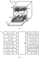
- FIG. 1 illustrates an exemplary dishwasher 10, in which various techniques and methods described herein can be realized.
- the dishwasher 10 is a household type built-in dishwasher 10, and therefore includes a front-loading door 12 that provides access to a washing tank 16 housed in a cabinet or a housing 14.
- the door 12 is generally hinged along a bottom edge and pivots between an open position illustrated in FIG. 1 and a closed position (not illustrated).
- a closed position not illustrated.
- one or more sliding shelves can be accessed, for example, a lower shelf 18 and an upper shelf 20, and various tableware to be washed are placed in the sliding shelves.
- the lower shelf 18 is supported by a roller 22, the upper shelf 20 is supported by a side rail 24, and each shelf can move between a loading (extending) position and a washing (retracting) position in a generally horizontal direction.
- Users' control over the dishwasher 10 is usually realized through a control panel (not shown in FIG. 1 ), and the control panel is usually arranged on the top or front of the door 12.
- the control panel can include various types of input and/or output apparatuses, such as various knobs, buttons, lights, switches, text and/or graphic display, touch screen, etc., and users can configure one or more settings through these apparatuses, and start and stop the washing cycle.
- the dishwasher 10 can include one or more tubular spray elements (TSEs) 26, so that the washing liquid is guided to the tableware placed in the shelves 18, 20.
- TSEs tubular spray elements
- the tubular spray elements 26 can rotate around their respective longitudinal axes, and can be discretely guided by one or more drive devices (not shown in FIG. 1 ) to control a direction in which each tubular spray element sprays the washing liquid.
- the washing liquid can be dispensed only by the tubular spray elements, which is however not limited in the present disclosure.
- one or more rotary spray arms can also be provided, for example, an upper spray arm 28, to guide an additional washing liquid onto the tableware.
- other sprayers such as wall-mounted sprayers, rack-mounted sprayers, swing type sprayers, fixed sprayers, rotary sprayers, centralized sprayers, etc.
- other sprayers can also be combined with one or more tubular spray elements.
- the embodiments discussed below will focus on implementing a method described below in a hinged door dishwasher.
- the method described herein can also be used in conjunction with other types of dishwashers in some embodiments.
- the method described herein can be used for commercial purposes.
- at least some of the methods described herein can be used in conjunction with dishwashers in other configurations, which includes dishwashers using sliding drawers or dishwaters with sinks, for example, dishwaters integrated in sinks.
- the dishwasher 10 can be controlled by a controller 30 which receives inputs from a plurality of components and drives the plurality of components in response thereto.
- the controller 30 can, for example, include one or more processors and a memory (not shown), and program codes can be stored in the memory to be executed by the one or more processors.
- the memory can be embedded in the controller 30, and can also be considered to include volatile memory and/or nonvolatile memory, cache memory, flash memory, programmable read-only memory, read-only memory, and etc., and include memory storage space physically located elsewhere in the controller 30, for example, in a mass storage device and/or a remote computer connected to the controller 30.
- the controller 30 can be connected to various components, such as an inlet valve 32 connected to introduce water into the washing tank 16, so that various washing liquids are formed when it is mixed with detergents, rinsing agents and/or other additives.
- the controller can also be connected to a heater 34, a pump 36, an air supply source 38, a drain valve 40 and a diverter 42.
- the heater 34 heats the fluid
- the pump 36 recirculates the washing liquid in the washing tank by pumping fluid to the washing arm and other spray devices in the dishwasher
- the air supply source 38 provides a pressurized air source to dry the tableware in the dishwasher
- the drain valve 40 is connected to the drain pipe to guide fluid out of the dishwasher
- the diverter 42 is used to control a route of the pumped fluid to different tubular spray elements, spray arms and/or other sprayers during the washing cycle.
- the single pump 36 can be used, and the drain valve 40 can be configured to guide the pumped fluid to the drain pipe or diverter 42 so that the pump 36 is used both to drain fluid from the dishwasher and to recirculate fluid in the dishwasher when the washing cycle is in progress.
- a separate pump can be used to drain the dishwasher and recirculate fluid.
- the diverter 42 may be a passive diverter which automatically sorts different outlets.
- the diverter 42 may be a controllable power diverter to direct fluid to a specific outlet as needed.
- the air supply source 38 can be realized as an air pump/air compressor or fan, and can include the heater and/or other air-conditioning devices to control temperature (for example, cooling and/or heating) and/or humidity (for example, removing moisture from the air and/or substances in the airflow) of the pressurized air output by the air supply source.
- the pump 36 and the air supply source 38 jointly realize a fluid supply of the dishwasher 10, so that a washing liquid source and a compressed gas source are provided for use respectively when a washing operation and a drying operation of the washing cycle are performed.
- the washing fluid can be considered as a fluid, which is usually a fluid that incorporates at least water, and in some cases, incorporates other components such as detergents, rinse aids, and other additives.
- the washing fluid can only include water during the rinsing operation. In some cases, the washing fluid can only include steam.
- the pressurized air is usually used for the drying operation, and can or cannot undergo heating and/or dehumidification treatment before being sprayed into the washing tank.
- the pressurized air cannot be used for a drying purpose in some embodiments, so the air supply source 38 can be omitted in some cases.
- the tubular spray element can only be used for spraying the washing fluid or spraying the pressurized air, while other sprayers or spray arms are used for other purposes. Therefore, the present disclosure is not limited to use the tubular spray element for spraying washing liquid and pressurized air.
- the controller 30 can also be connected to a distributor 44 to trigger the dispensing of detergent and/or rinsing agent into the washing tank at an appropriate time during the washing cycle.
- additional sensor and actuator including a temperature sensor 46 for determining the temperature of washing liquid, a door switch 48 for determining when to lock the door 12, and a door lock 50 for preventing the door from being opened during washing cycle can also be used.
- the controller 30 can be connected to a user interface 52 including various input/output apparatuses, such as rotary knobs, dials, sliders, switches, keys, lights, text and/or graphic displays, touch screen displays, loudspeakers, image capture device, microphones, etc., for receiving input from the user and communicating with the user.
- the controller 30 can also be connected to one or more network interfaces 54, for example, to connect to external apparatuses through a wired and/or wireless network (such as, Ethernet, Bluetooth, NFC, cellular, and other suitable networks).
- a wired and/or wireless network such as, Ethernet, Bluetooth, NFC, cellular, and other suitable networks.
- additional components can also be connected to the controller.
- one or more TSE drive devices 56 and/or one or more TSE valves 58 can be provided in some embodiments to control discretely one or more TSE arranged in the dishwasher 10.
- the controller 30 can be implemented outside the dishwasher, for example, in a mobile device, in a cloud computing environment, etc., so that at least a part of functions described herein can be implemented in a part implemented outside the controller.
- the controller 30 can be operated under the control of an operating system, and can execute or otherwise rely on various computer software applications, components, programs, objects, modules, and data structures, etc..
- the controller 30 can also be incorporated hardware logic to implement some or all of the functions disclosed herein.
- the sequence of operations executed by the controller 30 can be implemented by using program codes.
- the program codes include one or more instructions which reside at different times in various memories and storage devices, and the instructions execute operations that reflect required functions when one or more hardware-based processors read and execute the instructions.
- this program code can be distributed as a program produce in various forms, and the present disclosure is equally applicable regardless of the specific type of the computer readable medium used for actual execution and distribution including, for example, non-transitory computer readable storage medium.
- the various operations described herein can be combined, separated, reordered, undone, changed, omitted, parallelized, and/or supplemented with other technologies known in the art. Therefore, the present disclosure is not limited to specific sequence of operation described herein.
- FIGS. 1 to 2 Various changes and deformations of the dishwasher illustrated in FIGS. 1 to 2 are obvious to those of ordinary skill in the art, which will become apparent from the following description. Therefore, this application is not limited to the specific implementations discussed in the text.
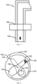
- the dishwasher can include one or more discretely orientable tubular spray elements, for example, a tubular spray element 100 connected to a drive device 102.
- the tubular spray element 100 can be configured as a tube or other elongated body arranged in the washing tank and rotates about a longitudinal axis L.
- the tubular spray element 100 is usually hollow, or at least includes one or more internal fluid channels in fluid communication with one or more holes 104 extending through its outer surface.
- Each hole 104 can be used to guide the spray fluid into the washing tank, and can be configured in various ways to provide various types of spray patterns, such as flow pattern, fan-shaped spray, concentrated spray, and etc.
- the holes 104 can also be configured as a fluid nozzle providing a swinging spray pattern.
- the holes 104 can all be positioned to guide fluid from the axis L along a same radial direction, thereby concentrating all spray fluid in a substantially same radial direction represented by an arrow R.
- the holes can be arranged differently around an outer surface of the tubular spray element, for example, providing sprays from two, three, or more radial directions to distribute the sprays on one or more arcs around a circumference of the tubular spray element, and so on.
- the tubular spray element 100 is in fluid communication with a fluid supply source 106, for example, by a port 108 of the drive device 102, to guide the fluid from the fluid supply source into the washing tank through one or more holes 104.
- the drive device 102 is connected to the tubular spray element 100, and is configured to guide discretely the tubular spray element 100 to each of a plurality of rotational positions around the longitudinal axis L. "Discrete guiding" means that the drive device 102 is capable of rotating the tubular spray element 100 approximately to a controlled angle of rotation (or at least within a range of the angle of rotation) about the longitudinal axis L.
- the drive device 102 can intelligently concentrate spray of the tubular spray element 100 among a plurality of rotation positions, instead of uncontrollably rotating the tubular spray element 100, or uncontrollably swing the tubular spray element 100 between two fixed rotation positions.
- rotating the tubular spray element to a controlled rotation angle can refer to an absolute rotation angle (for example, approximately 10° from an original position) or can refer to a relative rotation angle (for example, approximately 10° from a current position).
- the drive device 102 is also illustrated together with an electrical connection 110 for connecting to the controller 112, a housing 114 for housing various components in the drive device 102 is illustrated at the same time, which will be discussed in more detail below.
- the drive device 102 is configured as a base supporting an end part of the tubular spray element through a rotary connector, and placing effectively the tubular spray element in fluid communication with the port 108.
- spray pattern and cycle parameter can be increased and optimized for different situations.
- the tubular spray element near a center of the washing tank can be configured to rotate 360°, while a rotation of the tubular spray element located near a wall of the washing tank can be limited to about 180° to prevent spraying directly on any wall of the washing tank wall, and this is a major source of the dishwasher noise.
- a rotation speed of the tubular spray element can be changed during the entire rotation to provide a longer continuance time within some ranges of rotational position, thereby providing more concentrated washing for specific area in the washing tank, while still maintaining a 360° rotation.
- the control for the tubular spray element can include the control of rotational position, rotation speed or rate, and/or rotation direction.
- the drive device 102 includes a drive motor 116.
- the drive motor 116 may be an alternating current (AC) or a direct current (DC) motor, for example, a brushless direct current motor, a stepping motor, etc.
- the drive device 102 is mechanically connected to the tubular spray element 100 through a transmission assembly 101 such as a gearbox.
- the transmission assembly 101 includes a driving gear 118 and a driven gear 120 connected to the drive motor 116 and the tubular spray element 100 respectively.
- the drive device 102 is now described with reference to FIGS. 32 to 40 .
- the drive device 102 can control the rotation angle of the tubular spray element 100, thereby improving a cleaning effect of the tubular spray element.
- the dishwasher is a sink dishwasher arranged adjacent to a sink.
- the sink dishwasher can be made in one piece with the sink, and can also be detachably connected to the sink.
- the dishwasher provided in the present disclosure includes a washing tank 90, the tubular spray element 100, and the drive device 102, wherein the tubular spray element 100 is arranged in the washing tank 90, a first end of the tubular spray element 100 is a drive end, a second end of the tubular 100 is an inlet end, and a plurality of spraying holes are arranged on the tubular spray element 100; the drive device 102 is in transmission connection to the drive end of the tubular spray element 100, and is used to drive the tubular spray element 100 to rotate around the axis of the tubular spray element 100.
- the tubular spray element 100 rotates around the axis to change the spray angle, thereby changing the washing range.
- the tubular spray element 100 has a small volume, and occupies a small space, so the sink dishwasher has a larger accommodating space.
- the space occupied by the tubular spray element is equal to its actual volume, so it can ensure that the sink dishwasher has a larger accommodating space.
- the rotation angle of the tubular spray element 100 can be controlled accurately, thereby a washing angle and a washing range of the tubular spray element 100 can be controlled accurately, avoiding blind spots in cleaning, and ensuring the tableware can be washed thoroughly.
- the washing tank 90 has a plurality of wash zones, and each wash zone is correspondingly provided with one water supply system. Since different wash zones is in communication with different water supply systems, the different water supply systems can be set to different washing intensities, thereby different intensities of washing can be realized in different wash zones.
- the washing tank 90 includes a plurality of tank bodies partitioned from each other, and each of the tank bodies forms a wash zone.
- the washing tank 90 includes a first tank body 11 and a second tank body 17 arranged in a partition.
- the first tank body 11 forms a first wash zone
- the second tank body 17 forms a second wash zone.
- the water supply system includes a first water supply system 70 and a second water supply system 80.
- the first water supply system 70 is arranged corresponding to the first wash zone
- the second water supply system 80 is arranged corresponding to the second wash zone.
- the first wash zone can be set as a normal wash zone, and the second wash zone can be set as a powerful wash zone.
- the water supply system is a dual waterway system, and an intensity of the first water supply system 70 and the second water supply system 80 of the dual waterway system are set differently, so strong and weak partitions can realize in a single wash, thereby the user can clean tableware with different turbidity in a targeted manner.
- the tableware can also be cleaned in different degrees by passing through wash zones with different strengths in sequence. Specifically, the tableware to be cleaned can first enter the strong wash zone for washing, to wash food residues, and then enter the normal wash zone for washing, so as to clean oil stains thoroughly.
- the design of the present disclosure is not limited to this, in other embodiments, the first tank body 11 and the second tank body 17 can also be arranged in communication, in this way, the tableware can be conveniently transferred from the strength wash zone to the normal wash zone.
- the washing tank 90 is provided with a moveable partition 60, so that the washing tank 90 can be divided into the first tank body 11 and the second tank body 17.
- the partition 60 can separate the washing tank 90 into the first tank body 11 and the second tank body 17 when the partition 60 is mounted.
- the first tank body 11 is in communication with the second tank body 17 when the partition 60 is removed, so that the washing tank 90 can accommodate a larger volume of tableware, such as cookware, large dishes, etc.
- an inner wall face of the washing tank 90 is provided with a sliding chute extending in an up and down direction, and the partition 60 can be withdrawably mounted in the sliding chute.
- a hand clasping slot is arranged on an upper part of the partition 60, so that the partition 60 can be drawn conveniently.
- a sealing wall is protruded from the bottom wall of the washing tank 90 corresponding to the partition 60, and the bottom of the partition 60 is in sealing contact with the sealing wall.
- the top of the sealing wall is provided with a groove, and the bottom of the partition 60 is adapted to be embedded in the groove. In this way, not only the sealing performance of the partition 60 can be further improved, but the connection strength between the partition 60 and the washing tank 90 can also be improved.
- the partition 60 is arranged in the middle of the washing tank 90.
- the first water supply system 70 is arranged on an outer wall face of the bottom wall of the first tank body 11, the second water supply system 80 is arranged on the outer wall face of the bottom wall of the second tank body 17, and the first water supply system 70 and the second water supply system 80 are arranged symmetrically with respect to a plane where the partition is located. Since the partition 60 is located in the middle of the washing tank 90, the structures of the first tank body 11 and the second tank body 17 are symmetrical, and the first water supply system 70 and the second water supply system 80 have a similar structures and a same weight.
- the first water supply system 70 is mounted on the bottom wall face of the first tank body 11, and the second water supply system 80 is mounted on the bottom wall face of the second tank body 17, therefore the dishwasher can have a symmetrical and stable structure.
- a water softener and a motor pump of the water supply system are arranged on a diagonal line of the bottom wall of the tank body, and a water cup assembly of the water supply system is located between the water softener and the motor pump.
- the first water supply system 70 includes a first water softener 71, a first water cup assembly, a first motor pump 72, a first water supply pipe 73 connected in sequence, and a first connecting pipe in communication with the first water softener 71, the first water cup assembly, and the first motor pump 72;
- the first motor pump 72 and the first water softener 71 are arranged on the diagonal line of the bottom wall of the first tank body 11; and/or
- the second water supply system 80 includes a second water softener 81, a second water cup assembly, a second motor pump 82, a second water supply pipe 83 connected in sequence, and a second connecting pipe in communication with the second water softener 81, the second water cup assembly, and the second motor pump 82; the second motor pump 82 and the second water softener 81 are arranged on the diagonal line of the bottom wall of the second tank body 17.
- the first water supply system 70 and the second water supply system 80 are staggered distribution. Specifically, the first water softener 71 extends to a side of the second water supply system 80; and/or, the second motor pump 82 extends to a side of the first water supply system 70.
- the water supply system further includes a pressure keeping pipe in communication with the motor pump and the water supply pipe.
- a diameter of the pressure keeping pipe is larger than a diameter of the water supply pipe, so that the water pressure of the water supply pipe can be made more stable.
- the drive device 102 is used to drive the tubular spray element 100 to rotate around its axis.
- the drive device 100 includes a mounting housing 103, a transmission assembly 101, and a drive motor 116, wherein the transmission assembly 101 is arranged in the mounting housing 103, the drive motor 116 is arranged on the mounting housing 103, and the drive shaft of the drive motor 116 is connected to the transmission assembly 101.
- the drive device 102 proposed in the present disclosure can drive the tubular spray element 100 to rotate, the washing angle of the tubular spray element 100 can be controlled actively, the cleaning blind spots can be avoided, and the tableware can be cleaned thoroughly.
- the drive motor 116 is arranged on the mounting housing 103, and the transmission assembly 101 is arranged in the mounting housing 103, the modularization of the drive device 102 can be realized, thereby the trouble of separately mounting the transmission assembly 101 and the drive motor 116 can be avoided.
- the modular of the drive device 102 can be easily mounted in different mounting environments, therefore which can be widely used in the sink dishwashers, the cabinet dishwashers, desktop dishwashers, and other types of products.
- the drive device proposed in present disclosure is not only widely used in various dishwashers, but also can be used in cleaning apparatuses for fruit and vegetable mechanisms, medical apparatuses, and other devices.
- the transmission assembly 101 includes a driving gear 118 connected to the drive motor 116 and a driven gear connected to the driving gear 118.
- the transmission assembly 101 is a gear transmission assembly.
- the driven gear includes a first driven gear 221 and a second driven gear 223 adapted to mesh with both sides of the driving gear 118, and the first driven gear 221 and the second driven gear 223 are symmetrically distributed on both sides of the driving gear 118.
- the tubular spray element 100 includes a first tubular spray element and a second tubular spray element.
- the first driven gear 221 is connected to the first tubular spray element
- the second driven gear 223 is connected to the second tubular spray element. Since the first driven gear 221 and the second driven gear 223 are symmetrically distributed on both sides of the driving gear 118, the first driven gear 221 and the second driven gear 223 can rotate smoothly. More importantly, the first driven gear 221 and the second driven gear 223 are symmetrically distributed on both sides of the driving gear 118, thereby the structure of gear transmission assembly 101 can be made compact, and the miniaturization of the gear transmission assembly 101 can be realized.
- the first driven gear 221 is provided with a first limiting tooth 221a
- the second driven gear 223 is provided with a second limiting tooth 223a.
- the first limiting gear 221a is used to limit a limit position to rotate counter-clockwise
- the second limiting tooth 223a is used to limit a limit position to rotate clockwise.
- the mounting housing 103 includes a front housing 1031 and a rear housing 1032 that are detachably connected.
- the front housing 1031 and the rear housing 1032 are buckled to form a mounting cavity by fastening, and the transmission assembly 101 is provided in the mounting cavity.
- a periphery of the front housing 1031 is provided with a plurality of first fixing holes at an interval
- a periphery of the rear housing 1032 is provided with a plurality of second fixing holes corresponding to the plurality of first fixing holes.
- Positioning columns 111 are protrudingly provided on the inner wall face of the front housing 1031 close to the rear housing 1032, and the driving gear 118 and the driven gear are provided with mounting holes corresponding to the positioning columns 111.
- the positioning columns 111 are in clearance fit with the mounting holes, the mounting of the driving gear 118 and the driven gear can be conveniently realized by matching the positioning pin 111 and the mounting hole.
- the transmission assembly 101 is a gear-connecting rod transmission assembly.
- the gear-connecting rod transmission assembly 101 includes a drive motor 116, a driving gear 118, a connecting rod 119, and a driven gear 120 that are connected in turn, wherein the driven gear 120 includes a first driven gear 221 and a second driven gear 223.
- the tubular spray element 100 includes a first tubular spray element and a second tubular spray element.
- the first driven gear 221 is connected to the first tubular spray element
- the second driven gear 223 is connected to the second tubular spray element.
- the linkage mode of the gear-connecting rod 119 transmission assembly will now be illustrated.
- the drive motor 116 transmits the drive force to the driving gear 118, and the driving gear 118 is connected to the first driven gear 221; and then the first driven gear 221 transmits the drive force to the second driven gear 223 through the connecting rod 119; the first driven gear 221 is connected to the first tubular spray element, and the second driven gear 223 is connected to the second tubular spray element, thereby the drive force can be transmitted to the first tubular spray element and the second tubular spray element.
- the transmission assembly is provided with a transmission part, a transmission end of the tubular spray element is provided with a mating part, and the mating part is in transmission connection with the transmission part.
- the transmission part is a hexagon transmission shaft fixed on the driven gear of the transmission assembly.
- the mating part is a hexagon hole opened at the transmission end, and the hexagon transmission shaft is adapted to be inserted in the hexagon hole.
- the design of the present disclosure is not limited to this, in other embodiments, the positions of the hexagon transmission shaft and the hexagon hole can be reversed, that is, the transmission assembly is provided with the hexagon hole, and the transmission end of the tubular spray element is provided with the hexagon transmission shaft.
- a structure of the transmission part is not limited to a hexagon transmission shaft, but can also be a transmission shaft with a rectangular cross section, a transmission shaft with a triangular cross section, etc..
- a stepped shaft is also provided between the hexagon transmission shaft and the gear. In this way, a stable connection between the hexagon transmission shaft and the gear can be ensured.
- An outer wall of the washing tank 90 is provided with a plurality of fixing members, and the mounting housing 103 is provided with connecting members configured to be fixed with the fixing members.
- the connecting members are fitted and fixed with the fixing members.
- the fixing members include a first fixing member 19 and a second fixing member 15 spaced apart in a first direction, a plurality of the first fixing members 19 are arranged at an inerval in a second direction, and a plurality of the second fixing members 15 are arranged at an inerval in the second direction;
- the connecting member includes a first connecting member 121 and a second connecting member 123 spaced apart in the first direction, a plurality of the first connecting members 121 are arranged at an inerval in the second direction, and a plurality of the second connecting members 123 are arranged at an inerval in the second direction; the first direction is perpendicular to the second direction.
- the first direction is an up-down direction
- the second direction is a front-rear direction. Since the fixing members and the connecting member are both spaced in a plurality in the up-down direction and the front-rear direction, the stability of the drive device 102 and the washing tank 90 after mounting can be ensured.
- the first fixing member 19 is formed with a mounting groove extending through the first fixing member in the first direction; the first connecting member 121 is provided with a guide portion 121a protruding beyond the first connecting member and extending along the first direction, and the guide portion 121a is adapted to be inserted into the mounting groove.
- the mounting of the guide portion 121a and the mounting groove has a positioning function, so that the mounting of the drive assembly and the washing tank 90 can be facilitated.
- the mounting process of the drive assembly and the washing tank 90 will now be described in detail. Firstly, insert the guide portion 121a into the mounting groove. After the guide portion 121a is mounted in the mounting groove, the first fixing member 19 is aligned with the mounting hole on the first connecting member 121, and the second fixing member 15 is aligned with the mounting hole on the second connecting member 123. At this time, the drive assembly can be mounted on the outer wall of the washing tank 90 by inserting screws or rivets into the mounting holes.
- an optional position sensor 122 can be arranged within the tubular spray element driver 102 to determine the rotational position of the tubular spray element 100 about the axis L.
- the position sensor 122 may be an encoder or a Hall sensor, or the position sensor 122 can be implemented in other ways, for example, integrated in a stepper motor.
- the rotational position of the motor is used to determine the rotational position of the tubular spray element.
- the position sensor 122 can also only sense a limited rotational position around the axis L (for example, an original position, 30 or 45° increments, etc.).
- time and programing logic can be used to control the rotational position, for example, relative to the original position, and in some cases, the rotational position can be controlled without feedback from the motor or the position sensor.
- the position sensor 122 can also be arranged outside the drive device 102.
- the internal passage 124 of the tubular spray element 100 is in fluid communication with the internal passage 126, and the internal passage 126 leads to the port 108 (not illustrated in FIG. 4 ) in the drive device 102 through the rotary connector 128.
- the connector 128 is formed by the bearing 130 mounted within the passage 126, wherein, one or more deformable sheets are arranged at the end of the tubular spray element 100 to fix the tubular spray element 100 to the drive device 102.
- a seal 132 for example, a lip seal, can also be formed between the tubular spray element 100 and the drive device 102.
- Other ways of providing fluid-flow while rotatably connecting the tubular spray element can be used in other embodiments.
- valve 140 may also be desirable to combine the valve 140 into the drive device 142 to regulate the flow of fluid to the tubular spray element 144 (for clarity, other elements of the drive device 142 have been omitted in FIG. 5 ).
- the valve 140 in some embodiments may be a switching valve, or it in other embodiments may be a variable valve that controls the flow rate.
- the valve may be arranged outside the drive device, or separated from the drive device in other ways, and it can be dedicated to the tubular spray element or used to control a plurality of tubular spray elements.
- the valve 140 can be integrated or otherwise adjacent to the rotary connector between the tubular spray element 144 and the drive device 142.
- the water By adjusting the flow of fluid-flow to the tubular spray element, for example, by selectively closing the tubular spray element, the water can be saved and/or the full hydraulic power can be promoted by a smaller number of tubular spray elements, and a high pressure zone can be formed.
- the actuation of the valve 140 can be independent of the rotation of the tubular spray element, for example, using a diaphragm valve, a butterfly valve, a gate valve, a plunger valve, a bucket valve, a valve with a rotatable disc, a ball valve, etc.
- the valve 140 can be actuated by a solenoid, a motor or other independent mechanism from the mechanism that rotates the tubular spray element 144.
- the valve 140 can be actuated by the rotation of the tubular spray element 144.
- the tubular spray element 144 rotating to a predetermined rotational position can be a stop valve 140, for example, the valve 140 includes an arc-shaped passage that allows fluid-flow to flow only at a rotational position within a specific range.
- valve 150 in FIG. 6 the valve can be actuated by rotating excessively the tubular spray element.
- the valve 150 includes a port 152 that is selectively closed by a door 154 that pivots about a pin 156.
- the door 154 (for example, by a spring) is biased to a position illustrated by the solid line in FIG. 6 , and includes a branch portion 158 that is selectively connected to a stopper 160 at the predetermined rotational position that represents one end of the range R1 of the effective spray position of the tubular spray element.
- the branch portion 158 is connected to the stopper 160 to pivot the door 154 to a position 154' illustrated by the dotted line and the sealing port 152.
- the valve can be actuated by reverse rotation of the tubular spray element.
- the valve 170 includes two ports 172 that are selectively closed by a door 174 that pivots about a one-way bearing 176.
- the door 174 (for example, by a spring) is biased to a position illustrated by the solid line in FIG. 7 .
- the door 174 keeps in a position that allows the fluid-flow through the port 172 when the tubular spray element rotates in a clockwise direction. However, when rotating counterclockwise, the door 174 is rotated to a position 174' illustrated in the dotted line to seal the port 172 by the action of the one-way bearing 176.
- the valve 180 may be a variable valve, for example, a diaphragm valve, including a port 182 that is selectively adjusted by a plurality of diaphragm members 184.
- Each diaphragm member 184 includes a pin 186 that sits on a track 188 to change the size of opening of the port 182.
- the valve 188 can be independently actuated by the rotation of the tubular spray element (for example, by the solenoid or the motor), or, can be actuated via the rotation of the tubular spray element by using an appropriate mechanical connecting rod, for example, rotation to the predetermined position, excessive rotation, or reverse rotation.
- the valve 180 can be configured to close by a predetermined amount by reverse rotation, but remains open when rotated in both directions. Specifically, the valve 180 can be configured to open the valve when the pin 186 is placed on any branch portion of the U-shaped track; but when the pin 186 is placed in the center portion of the track, the valve is closed, and the track has a shortest radial distance from the center line of the valve.
- the valve 180 can be configured such that when the tubular spray element rotates in one direction and the pin 186 is placed at one end of the track 188, the valve is fully opened; and then, when the tubular spray element is reversely rotated in an opposite direction by a first preset amount (for example, a preset number of degrees), the pin 186 travels along the track 188 to the center portion to fully close the valve. Then, when the tubular spray element reversely rotates in the opposite direction and exceeds the first preset amount, the pin 186 continues to travel along the track 188 to the opposite end, thereby reopening the valve, so that the valve remains open by continuing to rotate in the reverse direction.
- a first preset amount for example, a preset number of degrees
- the tubular spray element can be mounted in the washing tank in various ways. As illustrated in FIGS. 1 and 3 (as described above), in some embodiments, the tubular spray element can be mounted on the wall (for example, side wall, rear wall, top wall, bottom wall or door) of the washing tank, and can be oriented in various directions, for example, horizontal, vertical, front-and-back, left-and-right or at a certain angle.
- the drive device can be arranged in the washing tank, for example, mounted on the wall of the washing tank or a supporting structure such as a shelf, or alternatively, part or all of the tubular spray element drive device can be placed outside the washing tank, for example, so that a part of the drive device or the tubular spray element protrudes through the hole in the washing tank.
- a magnetic drive device can be used to drive the tubular spray element in the washing tank, and the tubular spray element uses an externally mounted drive device.
- tubular spray element 200 in FIG. 9 unlike the tubular spray element 100 in FIG. 3 , which is mounted in a cantilever manner, the tubular spray element can also be mounted on the wall 202 of the washing tank. And the two ends thereof are supported by hubs 204, 206, one or two ends of which can include components of the drive device. At this point, the tubular spray element 200 extends generally parallel to the wall 202, rather than extending generally perpendicular to the wall 202 like the tubular spray element 100 in FIG. 3 .
- the tubular spray element may be a rack-mounted type.
- the tubular spray element 210 illustrated in FIG. 10 can be mounted on the shelf (not shown), and can be docked to a docking port 216 on the wall 212 of the washing tank through a docking portion 214.
- the drive device also is also a rack-mounted type. Therefore, in addition to the fluid connection between the docking portion 214 and the docking port 216, the docking portion 214 and the docking port 216 are also provided with a plurality of cooperating contacts 220, 121, so as to provide power to the drive device 218 and electrically communicate with the controller 224.
- the tubular spray element 230 may be a rack-mounted type, but for the drive device 232 mounted on the wall 234 of the washing tank instead of the rack-mounted type, the tubular spray element 230 may be separated from it.
- the docking portion 236 and the docking port 238 provide fluid communication with the tubular spray element, and at the same time can rotate the tubular spray element 230 about its longitudinal axis under the control of the drive device 232.
- the controller 240 provides control of the drive device 232.
- the drive device 232 can include a rotatable and keyed channel in which the end of the tubular spray element can be accommodated.
- a dishwasher 250 illustrated in FIG. 12 next, which includes a washing tank 250 and upper and lower shelves 254, 256, and has a plurality of tubular spray elements 258, 260, 262 distributed throughout the washing tank 252 for circulating the washing fluid inside the dishwasher.
- the tubular spray element 258 may be a rack-mounted type, supported by the lower side of the upper shelf 254, and extends form back to front in the washing tank 252.
- the tubular spray element 258 may also be docked with a rear wall-mounted drive device (not shown in FIG. 12 ), for example, as discussed above in connection with FIG. 11 .
- the tubular spray element 258 can be rotatably supported at one or more points along its respective longitudinal axis.
- the tubular spray element 258 can spray upwards into the upper shelf 254 and/or downwards into the lower shelf 256, and in some embodiments, can be used to concentrate the washing fluid on the cutlery basket or other areas of any shelf to provide centralized washing.
- the tubular spray element 260 can be wall-mounted below the lower shelf 256 in an manner, and its two ends can be supported by the side walls of the washing tank 252, extend from left to right, and are generally transverse to the tubular spray element 258.
- each tubular spray element 258, 260 can have a separate drive device, while in other embodiments, some or all of the tubular spray elements 258, 260 can be mechanically connected and driven by a common drive device.
- tubular spray elements 258, 260 can provide sufficient washing action and coverage by themselves.
- additional tubular spray elements can also be used, for example, the tubular spray element 262 above the upper shelf 254 supported on one or both of the top wall and the rear wall of the washing tank 252.
- additional spray arms and/or other sprayers can be used. It should also be understood that although FIG. 12 shows ten tubular spray elements, in other embodiments a greater or smaller number of tubular spray elements can be used.
- the example dishwasher 300 may include three drive devices 302, 304, 306 interconnected by fluid supply pipes 308, 310.
- the drive device 302 can directly drive the tubular spray element 312 similar to the driver 102 illustrated in FIG. 3 , and drive the additional tubular spray element 314, which extends generally transverse to the tubular spray element 312, and is mechanically connected by a mechanical connection including two gears 316, 318, and fluidly connected by a pipe 320.
- the driver 304 can directly drive the tubular spray element 322 and the additional tubular spray element 324, which extends generally transverse to the tubular spray element 322, and is mechanically connected by the mechanical connection including two gears 326, 328, and fluidly connected by the pipe 330.
- the driver 306 can directly drive a pair of tubular spray elements 332, 334 that extend along a similar longitudinal axis and include drive gears 336, 338, respectively.
- the tubular spray elements 340, 342, 344, and 346 are connected to the tubular spray elements 332, 334 at an angle of about 45°.
- the tubular spray elements 340, 342, 344, and 346 are mechanically connected to gears 336, 338 through corresponding mechanical connections including gears 348, 350, 352, and 354, and fluidly connected through headers 356, 358.
- FIG. 13 can be implemented at different heights in the washing tank, for example, bottom, top, and/or intermediate position, and can be mounted on the shelf or the wall of the washing tank. It should also be understood that different embodiments can support countless variations in the direction, number, and orientation of the tubular spray elements.
- the plurality of tubular spray elements can be driven by the same drive device, and can be provided in the washing tank, and can extend in different directions and/or in different planes to provide greater coverage in the washing tank.
- tubular spray element in addition to rotating around its longitudinal axis, can also be rotatable, or can be moved in other ways.
- a dishwasher 400 is illustrated in FIG. 14 , which includes a washing tank 406 and first and second tubular spray elements 402, 404.
- each tubular spray element 402, 404 can also rotate around a corresponding hub 408, 410 arranged at the opposite corner of the washing tank 406.
- Each hub 408, 410 defines an axis of rotation that is substantially transverse to the longitudinal axis of the corresponding tubular spray elements 402, 404, and is arranged near one end of the corresponding tubular spray elements 402, 404, such that the opposite ends of the corresponding tubular spray elements 402, 404 move along arc-shaped paths A1, A2, for example, to the positions 402', 404' illustrated in dotted lines.
- each hub 408, 410 may include the plurality of drive devices, including a drive device for rotating the tubular spray elements 402, 404 around their longitudinal axis, and a drive device for rotating the tubular spray elements 402, 404 around their transverse rotation axis.
- the two drive devices can also be interconnected and/or share the same components (for example, a gear and/or a motor).
- the drive device for rotating around the longitudinal axis and/or the transverse axis of rotation can be separated from the hubs 402, 404, and is mechanically connected in an appropriate manner understood by those of ordinary skill in the art who benefit from the present disclosure.
- the movement of the tubular spray element along the paths A1, A2 can substantially cover the entire cross-section (including the corners) of the washing tank 406, thereby minimizing the blind area where insufficient spray occurs.
- the tubular spray elements can be configured to rotate on different planes (for example, at different heights in the washing tank), or alternatively, the control of the position of each tubular spray element 402, 404 along the paths A1, A2 can be coordinated to avoid collision, even if the elements are in the same plane.
- FIG. 15 in addition to or instead of the rotatable illustrated in FIG. 14 , the tubular spray element can also be movable.
- FIG. 15 particularly shows a dishwasher 420, which includes a washing tank 422 and a pair of tubular spray elements 424, 426 supported by tracks 428, 430 to move approximately linearly along the axes A3, A4 (for example, reaching the positions illustrated in the dotted lines 424', 426'), the axes A3, A4 are generally transverse to the longitudinal axis of the corresponding tubular spray element 424, 426.
- Each track 428, 430 can include a plurality of drive devices, which include a drive device for moving the tubular spray elements 424, 426 around their longitudinal axes, and a drive device for moving the tubular spray elements 424, 426 along their transverse axes A3, A4.
- the two drive devices can also be interconnected and/or share the same components (for example, a gear and/or a motor).
- the tracks 428, 430 can be configured to use a single motor to "roll" the tubular spray elements 424, 426 between the corresponding positions 424, 424' and 426, 426' like a log, and in some cases, the valve can be configured to close the fluid-flow at a specific rotational position (for example, to avoid hitting the wall of the washing tank).
- the drive device for rotating about the longitudinal axis and/or moving along the transverse axis can be separated from the tracks 428, 430, and is mechanically connected in an appropriate manner understood by those of ordinary skill in the art who benefit from the present disclosure.
- a deflector can be used in combination with a tubular spray element to promote fluid diffusion and/or prevent fluid from hitting the tub wall.
- the deflector can have various outlines and shapes.
- the dishwasher includes a shelf 440, and a plurality of tubular spray elements 444 (illustrated from their respective ends) are provided below the shelf.
- the deflectors such as the deflector 446, 448, and 450, can be used to deal with of fluid distribution problems associated with having a fixed spray device.
- the deflector 446 can have an angular shape and be used to restrict fluid from being directed to the wall of the washing tank, while the deflector 448 can have a star-shaped cross-section, and can be used by a plurality of tubular spray elements 444 to direct the fluid upward into the shelf 442 or downward into the lower shelf (not shown) in a way only through properly guiding the tubular spray element.
- the deflector 450 can be planar in nature, and can cause one tubular spray element 444 to spray upward and the other tubular spray element to spray downward.
- the deflector can be integrated into the shelf, for example, integrated into its wire as illustrated by the deflector 446, or can be mounted on the shelf or otherwise supported by the shelf.
- the deflector can be mounted on the wall of the washing tank as illustrated by the deflectors 448 and 450.
- the deflector illustrated in FIGS. 16 to 17 is fixed in nature, in some embodiments the deflector can also be movable, for example, to redirect fluid in the plurality of directions, for example, such as deflection as illustrated by the deflector 450, it is connected to a motor 452 capable of rotating the deflector 450 around its longitudinal axis.
- the orientation of the deflector can be controllable, so that the spray fluid directed to the deflector through the tubular spray element can be controllably redirected.
- the deflector can use a plurality of different cross-sectional profiles, and in particular, can be configured for specific applications.
- the profile of the deflector can also change along its length.
- the dishwasher 460 includes a washing tank 462 having a plurality of tubular spray elements 464 and a plurality of deflectors therebetween, such as the deflectors 466, 468, and 470.
- the deflector 466 is corrugated along its length, and the deflector 468 forms curved along its shape.
- the deflector 470 has a combination of angle and curve.
- other profiles can be used.
- the tubular spray element for spraying the washing fluid (for example, the washing liquid) onto the tableware during the washing operation of the washing cycle
- the tubular spray element can also be used to spray the pressurized air onto the tableware during the drying operation of the washing cycle, for example, to blow away water collected on cups and tableware after rinsing is completed.
- the washing tank 482 can include upper and lower shelves 484, 486 and a plurality of tubular spray elements 488, 490, 492, and 494 configured as "air knives" to spray the pressurized air during the drying operation.
- the tubular spray elements 488, 490 can be arranged above the upper shelf 484 located on the top corner of the washing tank 482, thereby the tubular spray elements 488, 490 can be restricted to through a rotational movement of about 90°.
- the tubular spray elements 492, 494 are arranged between the shelves 484, 486 along the side wall of the washing tank 482, and are restricted to through a rotational movement of about 180°.
- tubular spray elements 488, 490, 492, and 494 are dedicated to spray pressurized air. Therefore, the tubular spray elements 488, 490, 492, and 494 can have hole sizes and are appropriately numbered according to their respective drying functions.
- an additional tubular spray element (not shown) can be used to spray the washing liquid, while in other embodiments, other sprayers can be used, such as wall-mounted sprayers, spray arms, rack-mounted sprayers, etc.
- the tubular spray element may be dual-purposed and can be used to spray washing liquid and pressurized air for washing and drying operations in the washing cycle.
- the washing tank 502 includes upper and lower shelves 504, 506. Above the upper shelf 504 is a pair of top tubular spray elements 508, which are configured to spray downward through a rotation of about 180°.
- a pair of central tubular spray elements 510 and a pair of side wall tubular spray elements 512 are located directly below the upper shelf 504 and above the lower shelf 506.
- the pair of central tubular spray elements 510 are configured for rotation of 360°
- the pair of side wall tubular spray elements 512 are configured for rotation of about 180°.
- a pair of lower central tubular spray elements 514 configured for rotation of about 180° and a pair of lower corner tubular spray elements 516 configured for rotation of about 90° are located below the lower shelf 506.
- the tubular spray element can also be arranged to extend from one side to the other in the washing tank, instead of extending from back to front, or can also be arranged to extend in other desired orientations.
- each of the tubular spray elements 508 to 516, or at least one subset of the tubular spray elements 508 to 516 can be used to spray washing liquid and pressurized air singly or in combination.
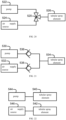
- FIG. 20 illustrates this arrangement, in which a three-way valve 520 selectively connects one or two of the pump 522 and the air supply source 524 to one or more tubular spray elements 526.
- valve 520 can connect only one of the pump 522 and the air supply source 524 to the tubular spray element 526 at a time, while in other embodiments, the valve 520 can be configured to coordinate the flow between the pump 522 and the air supply source 524.
- FIG. 21 illustrates an alternative arrangement, in which a pump 530 and an air supply source 532 are connected to one or more tubular spray elements 534 through corresponding one-way valves 536, 538, so that the pump 532 can be activated when the washing fluid needs to be sprayed, and the air supply source can be activated when the pressurized air needs to be sprayed.
- the one-way valves 536, 538 prevent backflow from occurring to another supply source, and in some embodiments, if necessary, the one-way valves 536, 538 also allow the two supply sources to work at the same time.
- FIG. 22 illustrates another alternative arrangement, in which different subsets of tubular spray elements 540, 542 are connected to a pump 544 and an air supply source 546, respectively.
- each tubular spray element 540, 542 can be optimized for its respective washing/drying function, and no mixing occurs between the pump 544 and the air supply source 546.
- the tubular spray elements can be closed individually, by selectively closing some tubular spray elements to reduce the amount of air required for drying, the air pressure can be generally maintained at a higher level. Otherwise, if all the tubular spray elements are active at the same time during the drying operation, the required air flow may ask for a larger capacity air pump or fan in the air supply source in order to generate sufficient air movement to forcibly move the water collected on any tableware. Since the volume of washing liquid that can be sprayed during the washing operation is relatively large, this worry may not be so great during the washing operation.
- FIG. 23 illustrates one such operation sequence for a dishwasher controller washing cycle, whereby during the washing operation (block 550), the plurality of tubular spray elements can be operated simultaneously to spray the washing liquid into the washing tank, and during the drying operation (block 552), the same tubular spray elements can be operated sequentially or individually to spray the pressurized air into the washing tank, thereby reducing the maximum amount of air that needs to be supplied in any given situation during the drying operation.
- FIG. 24 illustrates a dishwasher 600, which includes a washing tank 602, a door 604, an upper shelf 606 and a lower shelf 608.
- a dishwasher 600 which includes a washing tank 602, a door 604, an upper shelf 606 and a lower shelf 608.
- Various types of sprayers can also be used for washing tableware in this dishwasher, as well as to meet specific washing needs.
- some dishwasher designs can use rotatable spray arms, for example, the middle rotatable spray arm 610 and/or the lower rotatable spray arm 612 are respectively arranged below the upper shelf 606 and the lower shelf 608.
- Some designs can also include an upper rotatable spray arm (not visible in FIG. 24 ) arranged on the top wall of the washing tank 602.
- some dishwasher designs can include various sprayers or nozzles, for example, various wall-mounted nozzles 614 and/or various rack-mounted nozzles 616. Some sprayers or nozzles can be fixed, while other sprayers or nozzles can be rotatable, swingable, or otherwise movable to provide different spray patterns.
- some sprayers or nozzles can be configured for general coverage of the area inside the washing tank, some sprayers or nozzles can provide more powerful and/or concentrated sprays, and some sprayers or nozzles can be dedicated to specific tasks (for example, spray the items in the cutlery basket, the inside of the bottle, the surface of extremely dirty kitchenware, etc.).
- the tubular spray element can also be considered as a sprayer.
- these types of sprayers can also be connected to a liquid supply source 622 (for example, a pump) and an air supply source 624 through a hydraulic circuit 626.
- the hydraulic circuit 626 can spray the liquid (for example, washing liquid) and the pressurized air onto the tableware in the washing pipe through a sprayer.
- the hydraulic circuit 626 can include one or more supply pipes, ducts, diverters, etc., and one or more valves, for example, any of the various types of valves discussed above, including one-way valves and various valves that can be controlled by the controller 628.
- the controller 628 can also control either the liquid supply source 622 or the air supply source 624 (electrical connections are illustrated by dotted lines).
- the hydraulic circuit 626 can also be partially integrated into any one of the liquid supply source 622, the air supply source 624, and/or one or more sprayers 620.
- the hydraulic circuit cab be configured to inject the pressurized air from the air supply source 624 into the liquid-flow from the liquid supply source 622, although the present disclosure is not limited thereto.
- the hydraulic circuit can include many of the various arrangements discussed above in connection with FIGS. 20 to 23 .
- hydraulic circuit 626 can also deliver fluid to only part of the sprayer 620 and/or simultaneously deliver different fluid compositions to different sprayers or combinations of sprayers, and some additional sprayers in the dishwasher 600 can also be completely independent of the hydraulic circuit 626.
- the controller 628 can control the liquid supply source 622, the air supply source 624, the clutch 737, the air compressor 740, one or more motors (for example, a single motor of the liquid/air supply source), and/or the hydraulic circuit 626 to selectively spray liquid or pressurized air through the sprayer 620, that is, to spray the liquid through the liquid supply 622 or the pressurized air through the air supply 624, but not both at the same time.
- the controller 628 can control the liquid supply source 622, the air supply source 624, the clutch 737, the air compressor 740, one or more motors (for example, a single motor of the liquid/air supply source), and/or the hydraulic circuit 626 to selectively spray liquid or pressurized air through the sprayer 620, that is, to spray the liquid through the liquid supply 622 or the pressurized air through the air supply 624, but not both at the same time.
- the controller 628 can control the liquid supply source 622, the air supply source 624, and/or the hydraulic circuit 626 to simultaneously spray the liquid and the pressurized air through the sprayer 620, that is, substantially simultaneously spray the liquid from the liquid supply source 622 and the pressurized air from the air supply source 624. In some embodiments, this can effectively aerate the washing liquid, and in some embodiments, it can reduce water consumption. In addition, in some embodiments, this can allow the mechanical action of the sprayer to be changed or controlled.
- the control of the controller 628 can include the control of the hydraulic circuit 626, for example, by opening or closing one or more valves, by changing the position of a mixing valve or variable valve, by changing the fluid path between two different end points, etc.
- the controller 628 can also include the control of either the liquid supply source 622 or the air supply source 624, for example, by opening or closing any of the supply sources 622, 624 (for example, disengaging or engaging one or more clutches, changing the rotation of one or more motor shafts, different control of the one or more motors, turning the motors on or off), by changing the pressure or flow rate of any supply source 622, 624, or changing some other parameters of any supply source 622, 624 (for example, if supported, temperature, introduction of additives, pressure, etc.).
- the hydraulic circuit can be completely passive, and therefore the controller 628 cannot support the control of any components of the hydraulic circuit 626.
- the controller 628 can be configured to dynamically change the ratio of liquid and air when simultaneously supplying the liquid and the pressurized air to one or more sprayers (block 640) to control the output of one or more sprayers (block 642).
- Such changes can include, for example, temporarily opening or closing the liquid and/or air supply and/or valves connected to it to communicate alternate liquid and/or pressurized air, change the mixing valve to change the ratio of the delivered liquid and pressurized air, change the output, flow rate and/or pressure of one or two of the supply sources 622, 624, or other methods that can be understood by those of ordinary skill in the art. For example, in some cases, it may be necessary to inject the pressurized air into the washing liquid stream to make the sprayer produce a higher speed washing liquid.
- devices such as, but not limited to, dishwasher 700 can include a liquid supply source 722 and an air supply source 724 having a single actuator (For example, motor).
- a single motor 730 can selectively operate air and/or water supplied to one or more sprayers 720 (for example, the same or different sprayers).
- the single motor 730 can operate the air pump 725 of the air supply source and/or the water pump 723 of the water flow supply source to selectively operate water (for example, circulating water, recirculating water, and in some cases, such as detergent, rinsing agent and additional components of other additives), air or a combination of them are operated on one or more sprayers.
- the single motor 730 can also be used with the water pump 723, or drive an additional water pump to drain the contents of the washing tank during one or more dishwashing cycles.
- the single motor of the air supply source and the water flow supply source can be in fluid communication with the plurality of devices in the dishwasher or the equipment, and is not limited to one or more sprayers.
- other devices or functions in the equipment or dishwashers can include drying structures, materials, additives, filters or similar devices located in one or more chambers or air channels, ventilation, cooling/heating, recirculating air/water, drainage, etc.
- the air can be conditioned by heating, cooling and/or dehumidification.
- materials can be used for air conditioning, such as but not limited to metal shelf structure, zeolite, and lithium chloride, etc.
- a single motor of the air supply source and the water flow supply source can be used for laundry applications.
- the water pump 723 and the air pump 725 can form multiple configurations or configurations with a single or common motor 730.
- the water pump 723 and the air pump or blower 725 can be arranged at opposite ends 732, 734 of the motor 730, and connected to one or more shafts 736 protruding outwardly therefrom.
- the water pump 723 and the air pump 725 are arranged at the same end or side 732 of the motor 730, and are connected to one or more shafts 736 extending outwardly therefrom.
- the water pump 723 can be placed between the air pump 725 and the motor 730.
- the air pump 725 can be arranged between the water pump 723 and the motor 730.
- the air pump can be installed around the circumference of the water pump.
- the motor can be electric.
- the motor can be a variable speed or fixed speed motor.
- one or more air pumps 725 and one or more water pumps 723 can be operated together with the common motor 730 in various methods and ways to operate separately or together.
- the one or more clutches or connectors 737 can be used to start or stop the air pump 725 and/or the water pump 723.
- the one or more clutches 737 can be independently or collectively operated electronically and/or magnetically during one or more cycles.
- one or more clutches 737 can be arranged between the air pump 725 and the water pump 723 to operate the two pumps independently and/or simultaneously.
- one or more one-way bearings 739 can be used to start/stop the air pump 725 and/or the water pump 723.
- a one-way bearing 739 is used, which allows the drive shaft 736 to rotate clockwise to operate the water pump 723, and counterclockwise rotation of the drive shaft 736 can operate the air pump 725.
- the air pump 725 and the water pump 723 can rotate in the same direction or opposite directions.
- both the air pump and the water pump can be operated substantially simultaneously in a plurality of cycles (for example, when connectors, clutches, and/or one-way bearings are not used or are used).
- both the air pump and the water pump can be used simultaneously.
- the air pump and the water pump can be used together.
- the air compressor 740 can be used in the dishwasher 700. If an air compressor 740 is used, it can be in fluid communication with the air supply source, the hydraulic circuit, and/or the controller, thereby compressing the air separately supplied to one or more sprayers, and/or compressing the air mixed with water supplied to one or more sprayers. As illustrated in an embodiment in FIG. 30 , during one or more dishwashing cycles, the air compressor 740 can be in fluid communication with at least the air pump 725 to inject air with or without water/additives in one or more sprayers within one or more desired pressures or pressure ranges.
- these different types of sprayers can also be connected to one or two of a liquid supply source 722 (for example, a pump) and a air supply source 724 via a single motor 730 through a hydraulic circuit 726.
- the hydraulic circuit 726 causes one or two of the liquid (for example, washing liquid) and the pressurized air to be sprayed onto the tableware in the washing pipe via the sprayer.
- the hydraulic circuit 726 can include one or more supply pipes, conduits, diverters, etc., and one or more valves, for example, any of the various types of valves discussed above, including one-way valves and various valves that can be controlled by the controller 728, the controller 728 can also control either the liquid supply source 722 or the air supply source 724 (electrical connections are represented by dotted lines).
- the controller can operate the air compressor 740 to pressurize air or a combination of air and washing liquid.
- Part of the hydraulic circuit 726 can also be integrated into any one of the liquid supply source 722, the air supply source 724, the motor 730, and/or one or more sprayers 720.
- the hydraulic circuit can be configured to inject the pressurized air from the air supply source 724 into the liquid-flow from the liquid supply source 722, but the present disclosure is not limited to this.
- the hydraulic circuit 726 can include many of the various arrangements discussed above in combination with FIGS. 20 to 23 . It should also be understood that the hydraulic circuit 726 can also deliver fluid to only a part of the sprayer 720 and/or simultaneously deliver different fluid compositions to different sprayers or combinations of sprayers, and some additional sprayers in the dishwasher 700 can be completely independent of the hydraulic circuit 726.
- the controller 728 controls the liquid supply source 722, the air supply source 724 and can control the clutch 737, the air compressor 740, one or more motors (for example, a single motor 730 for the liquid/air supply source), and/ or the hydraulic circuit 726 to selectively spray the liquid or the pressurized air through the sprayer 720, that is, spray liquid from the liquid supply source 722 or spray pressurized air from the air supply source 724, but not both at the same time.
- different sprayers may spray air only, liquid only, or liquid and air.
Landscapes
- Engineering & Computer Science (AREA)
- Water Supply & Treatment (AREA)
- Washing And Drying Of Tableware (AREA)
Description
- This disclosure is based on and claims priority to
Chinese Patent Application Serial No. 201811208319.8, filed on October 16, 2018 US Patent Application Serial No. 16/129,192, filed on September 12, 2018 - The present disclosure relates to the technical field of kitchen appliances, and more particularly to a dishwasher and a method for operating same.
- A typical dishwasher uses independent motors: one for the rotating water pump and the other for the rotating air pump. In this way, since two motors are required to drive independently, resources such as time, energy, and water are usually wasted. In addition, the working process of the dishwasher includes: putting tableware in the dishwasher, selecting a washing procedure, pressing a corresponding selection switch, turning on a power supply, and enabling a procedure controller to start working. After the water reaches a certain temperature, it is sprayed through a spray hole of a spray arm, and the spray arm is rotated by a counterforce of the spray water, and continuously sprays water onto the tableware, thereby reducing the viscosity and adhesion of the grease, and then clear away dirt by spraying. Since the spray arm of the existing dishwasher is fixed on a base of the dishwasher, its drive force is a counterforce of the water spray, so a washing angle and washing range of the spray arm are relatively fixed. As a result, the existing dishwashers have dead spots in terms of cleaning, and the tableware cannot be thoroughly washed.
-
WO 2017/084693 A1 discloses a dishwasher comprising a washing chamber, a rack adapted to accommodate items to be washed by washing liquid within the washing chamber ,an arm, and an arm moving arrangement arranged to move the arm within the washing chamber. The dishwasher further comprises a water pump configured to supply liquid to the spray nozzles of the rotating arm during a washing phase and an air pump configured to supply pressurized air to the spray nozzles of the rotating arm during a drying phase. - To this end, one aspect of the present disclosure provides a dishwasher that drives an air pump and a water pump by a single motor to operate asynchronously or simultaneously, which can reduce the amount of water required for washing tableware in the dishwasher, can improve drying performance, and/or improve washing performance by accelerating water flow.
- Another aspect of the present disclosure further provides a method for operating the dishwasher.
- The dishwasher according to the invention includes: a washing tank; one or more sprayers arranged in the washing tank; and a liquid supply source and an air supply source that have a single motor and are operated by the single motor, a controller that is connected to the liquid supply source and the air supply source, wherein the liquid supply source includes a water pump driven by the single motor, and the water pump is in fluid communication with the one or more sprayers and is configured to supply liquid to the one or more sprayers to spray the liquid to tableware arranged in the washing tank; and wherein the air supply source includes an air pump driven by the single motor, and the air pump is in fluid communication with the one or more sprayers and is configured to supply pressurized air to the one or more sprayers to spray the pressurized air to the tableware arranged in the washing tank.
- For the dishwasher according to the invention, the air pump and the water pump are driven by the single motor to operate asynchronously or simultaneously, the amount of water required for washing tableware in the dishwasher can be reduced, avoiding waste of resources such as time, energy, water, the drying performance can be improved, and/or the washing performance can be improved by accelerating water flow.
- In some embodiments, the air pump and the water pump are mounted at opposite ends of the single motor, or the air pump and the water pump are mounted at one end of the single motor.
- In some embodiments, the water pump is arranged between the air pump and the single motor, or the air pump is arranged between the water pump and the single motor.
- In some embodiments, the single motor includes one or more clutches that operatively engage at least one of the water pump and the air pump.
- In some embodiments, the air supply source further includes at least one air compressor in fluid communication with the one or more sprayers.
- In some embodiments, the dishwasher further includes a hydraulic circuit connected among the liquid supply source, the air supply source, and the one or more sprayers.
- In some embodiments, the hydraulic circuit includes a first check valve and a second check valve, the first check valve is configured to restrict the liquid from flowing back to the air supply source, and the second check valve is configured to restrict the pressurized air from flowing back to the liquid supply source.
- In some embodiments, the hydraulic circuit includes a valve configured to selectively connect the one or more sprayers to either the liquid supply source or the air supply source.
- In some embodiments, the one or more sprayers includes a first sprayer and a second sprayer; the dishwasher further includes a first valve and a second valve; the first valve and a second valve are connected to the first sprayer and the second sprayer, respectively, to control a fluid that flows to the first sprayer and the second sprayer.
- In some embodiments, the dishwasher further includes a controller connected to the liquid supply source and the air supply source.
- In some embodiments, the controller is configured to control the liquid supply source, the air supply source and/or the hydraulic circuit to selectively spray the liquid or the pressurized air through the one or more sprayers.
- In some embodiments, the controller is configured to control the liquid supply source, the air supply source and/or the hydraulic circuit to spray the liquid through the one or more sprayers during a washing operation of a washing cycle, and to control the liquid supply source, the air supply source and/or the hydraulic circuit to spray the pressurized air through the one or more sprayers during a drying operation of the washing cycle.
- In some embodiments, the controller is configured to control the liquid supply source, the air supply source and/or the hydraulic circuit to simultaneously spray the liquid and the pressurized air through the one or more sprayers.
- In some embodiments, the dishwasher further includes one or more additional sprayers that are arranged in the washing tank and connected in fluid communication with only either the liquid supply source or the air supply source.
- In some embodiments, the single motor includes one or more one-way bearings that operatively engage at least one of the water pump and the air pump.
- In some embodiments, the dishwasher further includes a drive device configured to drive the sprayer, wherein the drive device includes: a mounting housing; a transmission assembly arranged in the mounting housing; and a drive motor having a drive shaft connected to the transmission assembly, the transmission assembly being connected to the sprayer.
- In some embodiments, the transmission assembly includes a driving gear connected to the drive motor and a driven gear connected to the driving gear, and the driven gear is connected to the sprayer.
- In some embodiments, the driven gear includes a first driven gear and a second driven gear, and the first driven gear and the second driven gear mesh with two sides of the driving gear and are symmetrically distributed on the two sides of the driving gear; the one or more sprayers includes a first sprayer and a second sprayer, the first driven gear is connected to the first sprayer, and the second driven gear is connected to the second sprayer.
- In some embodiments, the first driven gear is provided with a first limiting tooth, while the second driven gear is provided with a second limiting tooth; the first limiting tooth is configured to limit a limit position of counterclockwise rotation of the driving gear; and the second limiting tooth is configured to limit a limit position of clockwise rotation of the driving gear.
- In some embodiments, the transmission assembly further includes a connecting rod, the driven gear includes a first driven gear and a second driven gear, and the driving gear, the first driven gear, the connecting rod, and the second driven gear are in transmission connection in sequence; the one or more sprayers include a first sprayer and a second sprayer, the first driven gear is connected to the first sprayer, and the second driven gear is connected to the second sprayer.
- In some embodiments, the sprayer is a tubular spray element, and the drive device is configured to drive the tubular spray element to rotate around an axis of the tubular spray element.
- In some embodiments, the transmission assembly is provided with a transmission part, a transmission end of the tubular spray element is provided with a mating part, and the mating part is in transmission connection to the transmission part.
- In some embodiments, an outer wall of the washing tank is provided with a plurality of fixing members, a mounting housing is provided with connecting members configured to be fixed with the fixing members, and the connecting members are fitted and fixed with the fixing members.
- In some embodiments, the fixing members include a first fixing member and a second fixing member spaced apart in a first direction, a plurality of the first fixing members are arranged at an interval in a second direction, and a plurality of the second fixing members are arranged at an interval in the second direction; the connecting member includes a first connecting member and a second connecting member spaced apart in the first direction, a plurality of the first connecting members are arranged at an inerval in the second direction, and a plurality of the second connecting members are arranged at an interval in the second direction; the first direction is perpendicular to the second direction.
- In some embodiments, the first fixing member is provided with a mounting groove extending through the first fixing member in the first direction; the first connecting member is provided with a guide portion protruding beyond the first connecting member and extending along the first direction; and the guide portion is configured to be inserted into the mounting groove.
- A dishwasher according to embodiments of a second aspect of the present disclosure includes: a washing tank; a water pump; an air pump, wherein the water pump and the air pump are operated by a single motor;
- One or more first sprayers arranged in the washing tack, wherein the water pump is in fluid communication with the one or more first sprayers and is configured to supply liquid to the one or more first sprayers, to spray the liquid to tableware arranged in the washing tank; one or more second sprayers arranged in the washing tank, wherein the air pump is in fluid communication with the one or more second sprayers and is configured to supply pressurized air to the one or more second sprayers, to spray the pressurized air to the tableware arranged in the washing tank; and a hydraulic circuit in fluid communication with the one or more first sprayers and/or the one or more second sprayers, and configured to supply the liquid and the pressurized air from the water pump and/or the air pump driven by the single motor.
- In some embodiments, the dishwasher further includes a drive device, wherein the drive device includes: a mounting housing, a transmission assembly arranged in the mounting housing; and a drive motor, the transmission assembly is arranged in the mounting housing; a drive motor having a drive shaft connected to the transmission assembly, the transmission assembly being connected to the first sprayer and the second sprayer.
- In some embodiments, the transmission assembly includes a driving gear connected to the single motor and a driven gear connected to the driving gear; the driven gear includes a first driven gear and a second driven gear; the first driven gear and the second driven gear are configured to mesh with two sides of the driving gear and are symmetrically distributed on the two sides of the driving gear; the first driven gear is connected to the first sprayer, and the second driven gear is connected to the second sprayer.
- A method for operating a dishwasher according to embodiments of a third aspect of the present disclosure includes: operating a single motor to drive an air pump and a water pump; supplying liquid to one or more sprayers arranged in the washing tank of the dishwasher through the water pump of the dishwasher, to spray the liquid onto the tableware arranged in the washing tank; and supplying pressurized air to one or more sprayers through the air pump of the dishwasher, to spray the pressurized air onto the tableware arranged in the washing tank.
- In some embodiments, the liquid and the pressurized air are supplied simultaneously.
- In some embodiments, supplying the pressurized air includes injecting the pressurized air into the liquid supplied by the water pump.
- In some embodiments, the liquid and the pressurized air are supplied asynchronously.
- In some embodiments, the supply of the liquid is performed during a washing operation of a washing cycle, and the supply of the pressurized air is performed during a drying operation of the washing cycle.
- These and other advantages and characteristics that are characteristic of this disclosure are set forth in the appended claims and constitute a part of the specification. However, for a better understanding of this disclosure and the advantages and purposes that can be achieved by using this disclosure, please refer to the accompanying drawings and accompanying explanatory content, which describe exemplary embodiments of the disclosure. This overview is only used to introduce some concepts further described in the detailed description below. It is neither intended to identify key or essential features of the claimed subject matter nor is it intended to help limit the scope of the claimed subject matter.
-
-
FIG. 1 is a perspective view of a dishwasher according to some embodiments of the present disclosure. -
FIG. 2 is a block view of an exemplary control system of the dishwasher illustrated inFIG. 1 . -
FIG. 3 is a side perspective view of a tubular spray element and a drive device of the dishwasher illustrated inFIG. 1 . -
FIG. 4 is a partially cross-sectional view of a tubular spray element and a drive device illustrated inFIG. 3 . -
FIG. 5 is a partially cross-sectional view of another tubular spray element and drive device according to some embodiments of the present disclosure, which includes a valve for limiting the amount of flow to the tubular spray element. -
FIG. 6 illustrates an embodiment of the valve illustrated inFIG. 5 . -
FIG. 7 illustrates another embodiment of the valve illustrated inFIG. 5 . -
FIG. 8 illustrates yet another embodiment of the valve illustrated inFIG. 5 . -
Fig. 9 is a functional top plan view of an exemplary wall-mounted tubular spray element and drive device according to some embodiments of the present disclosure. -
FIG. 10 is a functional top plan view of an exemplary rack-mounted tubular spray element and drive device according to some embodiments of the present disclosure. -
FIG. 11 is a functional top plan view of another exemplary rack-mounted tubular spray element and drive device according to some embodiments of the present disclosure. -
Fig. 12 is a functional perspective view of a dishwasher including a plurality of tubular spray elements according to some embodiments of the present disclosure. -
FIG. 13 is a functional top plan view of an exemplary mechanically connected a plurality of tubular spray elements according to some embodiments of the present disclosure. -
FIG. 14 is a functional top plan view of an exemplary tubular spray element that can be rotated about a transverse axis according to some embodiments of the present disclosure. -
FIG. 15 is a functional top plan view of an exemplary tubular spray element that can be moved about a transverse axis according to some embodiments of the present disclosure. -
FIG. 16 is a functional front view of an exemplary tubular spray element system exemplary including different types of deflectors according to some embodiments of the present disclosure. -
FIG. 17 is a functional partial top plan view of another exemplary tubular spray element system including different types of deflectors according to some embodiments of the present disclosure. -
FIG. 18 is a functional front view of an exemplary tubular spray element system according to some embodiments of the present disclosure, the system being used to spray pressurized air during the drying operation of the washing cycle. -
FIG. 19 is a functional front view of an exemplary dual-purpose tubular spray element system according to some embodiments of the present disclosure, the system being used to selectively spray the washing fluid during the washing operation of the washing cycle, or the pressurized air during the drying operation of the washing cycle. -
FIG. 20 illustrates a block diagram of an exemplary tubular spray element system according to some embodiments of the present disclosure, which can selectively spray washing fluid and/or pressurized air. -
FIG. 21 illustrates a block diagram of another exemplary tubular spray element system according to some embodiments of the present disclosure, which can selectively spray washing fluid and/or pressurized air. -
FIG. 22 is a block diagram of another exemplary embodiment of a tubular spray element system according to some embodiments of the present disclosure, which can selectively spray washing fluid and/or pressurized air. -
FIG. 23 is a flowchart of an exemplary operation sequence for performing a washing cycle using the tubular spray element system according to some embodiments of the present disclosure. -
Fig. 24 is a perspective view of another dishwasher according to some embodiments of the present disclosure. -
FIG. 25 is a block diagram of hydraulic and electronic circuits of the dishwasher illustrated inFIG. 24 . -
FIG. 26 is a flowchart illustrating an exemplary operation sequence of simultaneously supplying liquid and pressurized air through one or more sprayers in the dishwasher illustrated inFIGS. 24 to 25 . -
FIG. 27 is a partial schematic diagram of another dishwasher, illustrating that an air supply source and a water flow supply source are operated by a single motor. -
FIG. 28 is a partial schematic diagram of another embodiment of an air supply source and a water flow supply source operated by a single motor. -
FIG. 29 is a partial schematic diagram of another embodiment of an air supply source and a water flow supply source operated by a single motor. -
FIG. 30 is a partial schematic diagram of another embodiment of an air supply source and a water flow supply source operated by a single motor. -
FIG. 31 is a block diagram of the hydraulic and electronic circuits of the dishwasher illustrated inFIG. 30 . -
FIG. 32 is a schematic structural diagram of an embodiment of a dishwasher of the present disclosure. -
FIG. 33 is a schematic diagram of a structure of the water supply system of the dishwasher. -
FIG. 34 is an exploded structural diagram of the installation of the drive device and the inner container of the dishwasher. -
FIG. 35 is a partially enlarged view of part A inFIG. 34 . -
FIG. 36 is a schematic cross-sectional view of the dishwasher. -
FIG. 37 is a partially enlarged view of part B inFIG. 36 . -
Fig. 38 is an exploded structural diagram of a first embodiment of the drive device. -
FIG. 39 is an exploded structural diagram of the first embodiment of the drive device from another angle of view. -
FIG. 40 is an exploded structural diagram of a second embodiment of the drive device. - Reference will be made in detail to embodiments of the present disclosure. The embodiments described herein with reference to drawings are explanatory, illustrative, and used to generally understand the present disclosure. The embodiments shall not be construed to limit the present disclosure. In the specification, it should be understood that terms such as "central", "longitudinal", "lateral", "length", "width", "thickness", "upper", "lower", "front", "rear", "left", "right", "vertical", "horizontal", "top", "bottom", "inner", "outer", "clockwise", "counterclockwise", "axial", "radially", "circumferential", etc. should be construed to refer to the orientation as then described or as illustrated in the drawings under discussion. These relative terms are for convenience of description and do not require that the present disclosure be constructed or operated in a particular orientation, so it is not to be constructed as a limit to the present disclosure.
- In some embodiments of the present disclosure, one or more tubular spray elements can be discretely guided by one or more drive devices, so that fluids such as washing liquid and/or pressurized air are sprayed into a washing tank of a dishwasher when a washing cycle is performed. In this regard, the tubular spray element can be considered to include an elongated body, and the elongated body may have a generally cylindrical shape in some embodiments, and may also have other cross-sectional profiles in other embodiments. The elongated body has one or more holes arranged on its outer surface and in fluid communication with a fluid supply source, for example, through one or more internal passages defined therein. The tubular spray element also has a longitudinal axis generally defined along its longest dimension, and rotates around this longitudinal axis. Moreover, the drive device is connected to the tubular spray element to discretely guide the tubular spray element to a plurality of rotational positions around the longitudinal axis. The tubular spray element may also have a cross-sectional profile that varies along the longitudinal axis. Therefore, it can be understood that the tubular spray element does not need to have a circular cross-sectional profile along its length, as illustrated in some embodiments herein. Additionally, in certain embodiments, one or more holes on the outer surface of the tubular spray element may be configured as nozzles, and may be fixed or moveable (for example, rotatable, swingable, etc.) relative to other holes on the tubular spray element. Furthermore, the outer surface of the tubular spray element may be defined on a plurality of components of the tubular spray element, that is, the outer surface does not need to be formed by a single integral component.
- In one embodiment, for example, a single brushed or brushless direct current motor can be used to drive a gear mechanism to rotate the corresponding tubular spray element, and each tubular spray element can be mounted on a base including a valve for cutting off and/or controlling a fluid, for example, a valve similar to a shutter in a camera, or a diaphragm valve that can be controlled by rotation in any direction. In some cases, the base can also include the direct current motor.
- As can be seen more clearly below, the combination of the direct current motor and the control valve dedicated to the tubular spray element opens up an additional factor that can be adjusted to improve efficiency, control and performance of the dishwasher. A controllable variable includes, for example, a speed, direction and/or activation of the tubular spray element. In certain embodiments, for a normal washing setup, all the tubular spray elements can be opened, and spray the washing liquid at a low speed. A tubular spray element located near a wall of the washing tank can be controlled to rotate in a mode that does not directly spray the washing liquid on a side face of the washing tank, and hence noise generated by a washing operation can be reduced. However, a tubular spray element located in a center of the washing tank can be allowed to rotate in all directions, and can change its direction occasionally. In some embodiments, a powerful area can be formed by turning off certain tubular spray elements (except for one or more elements located near a tableware basket), and hence a fluid pressure for powerful washing in active tubular spray elements can be increased. In addition, in some embodiments, the tubular spray elements can be controlled to rotate in a relatively small radian (for example, about 5 to 10°) to concentrate the spray in a small area/range. Moreover, in order to improve the efficiency, the tubular spray elements can be opened and closed cyclically to reduce the amount of the washing liquid required. In addition, it should be understood that, in some embodiments, a flow velocity and/or pressure of the fluid supply can also vary with the cyclical opening and closure of the tubular spray elements, or can be a flow velocity and/or pressure required to comply with the use of the tubular spray elements for fluid distribution.
- Now referring to the drawings, wherein like numerals refer to like parts throughout the views.
FIG. 1 illustrates anexemplary dishwasher 10, in which various techniques and methods described herein can be realized. Thedishwasher 10 is a household type built-indishwasher 10, and therefore includes a front-loading door 12 that provides access to a washing tank 16 housed in a cabinet or ahousing 14. Thedoor 12 is generally hinged along a bottom edge and pivots between an open position illustrated inFIG. 1 and a closed position (not illustrated). When thedoor 12 is in the open position, one or more sliding shelves can be accessed, for example, alower shelf 18 and anupper shelf 20, and various tableware to be washed are placed in the sliding shelves. Thelower shelf 18 is supported by aroller 22, theupper shelf 20 is supported by a side rail 24, and each shelf can move between a loading (extending) position and a washing (retracting) position in a generally horizontal direction. Users' control over thedishwasher 10 is usually realized through a control panel (not shown inFIG. 1 ), and the control panel is usually arranged on the top or front of thedoor 12. It should be understood that in different dishwasher designs, the control panel can include various types of input and/or output apparatuses, such as various knobs, buttons, lights, switches, text and/or graphic display, touch screen, etc., and users can configure one or more settings through these apparatuses, and start and stop the washing cycle. - In addition, in some embodiments of the present disclosure, the
dishwasher 10 can include one or more tubular spray elements (TSEs) 26, so that the washing liquid is guided to the tableware placed in theshelves tubular spray elements 26 can rotate around their respective longitudinal axes, and can be discretely guided by one or more drive devices (not shown inFIG. 1 ) to control a direction in which each tubular spray element sprays the washing liquid. In some embodiments, the washing liquid can be dispensed only by the tubular spray elements, which is however not limited in the present disclosure. For example, as illustrated inFIG. 1 , one or more rotary spray arms can also be provided, for example, anupper spray arm 28, to guide an additional washing liquid onto the tableware. In some embodiments of the present disclosure, other sprayers (such as wall-mounted sprayers, rack-mounted sprayers, swing type sprayers, fixed sprayers, rotary sprayers, centralized sprayers, etc.) can also be combined with one or more tubular spray elements. - The embodiments discussed below will focus on implementing a method described below in a hinged door dishwasher. However, it should be understood that the method described herein can also be used in conjunction with other types of dishwashers in some embodiments. For example, in some embodiments, the method described herein can be used for commercial purposes. In addition, at least some of the methods described herein can be used in conjunction with dishwashers in other configurations, which includes dishwashers using sliding drawers or dishwaters with sinks, for example, dishwaters integrated in sinks.
- Referring to
FIG. 2 , thedishwasher 10 can be controlled by acontroller 30 which receives inputs from a plurality of components and drives the plurality of components in response thereto. Thecontroller 30 can, for example, include one or more processors and a memory (not shown), and program codes can be stored in the memory to be executed by the one or more processors. The memory can be embedded in thecontroller 30, and can also be considered to include volatile memory and/or nonvolatile memory, cache memory, flash memory, programmable read-only memory, read-only memory, and etc., and include memory storage space physically located elsewhere in thecontroller 30, for example, in a mass storage device and/or a remote computer connected to thecontroller 30. - As illustrated in
FIG. 2 , thecontroller 30 can be connected to various components, such as aninlet valve 32 connected to introduce water into the washing tank 16, so that various washing liquids are formed when it is mixed with detergents, rinsing agents and/or other additives. The controller can also be connected to aheater 34, apump 36, anair supply source 38, adrain valve 40 and adiverter 42. Theheater 34 heats the fluid, and thepump 36 recirculates the washing liquid in the washing tank by pumping fluid to the washing arm and other spray devices in the dishwasher, and theair supply source 38 provides a pressurized air source to dry the tableware in the dishwasher, and thedrain valve 40 is connected to the drain pipe to guide fluid out of the dishwasher, and thediverter 42 is used to control a route of the pumped fluid to different tubular spray elements, spray arms and/or other sprayers during the washing cycle. In some embodiments, thesingle pump 36 can be used, and thedrain valve 40 can be configured to guide the pumped fluid to the drain pipe ordiverter 42 so that thepump 36 is used both to drain fluid from the dishwasher and to recirculate fluid in the dishwasher when the washing cycle is in progress. In further embodiments, a separate pump can be used to drain the dishwasher and recirculate fluid. In some embodiments, thediverter 42 may be a passive diverter which automatically sorts different outlets. However, in some other embodiments, thediverter 42 may be a controllable power diverter to direct fluid to a specific outlet as needed. In different embodiments, theair supply source 38 can be realized as an air pump/air compressor or fan, and can include the heater and/or other air-conditioning devices to control temperature (for example, cooling and/or heating) and/or humidity (for example, removing moisture from the air and/or substances in the airflow) of the pressurized air output by the air supply source. - In the illustrated embodiment, the
pump 36 and theair supply source 38 jointly realize a fluid supply of thedishwasher 10, so that a washing liquid source and a compressed gas source are provided for use respectively when a washing operation and a drying operation of the washing cycle are performed. The washing fluid can be considered as a fluid, which is usually a fluid that incorporates at least water, and in some cases, incorporates other components such as detergents, rinse aids, and other additives. For example, the washing fluid can only include water during the rinsing operation. In some cases, the washing fluid can only include steam. The pressurized air is usually used for the drying operation, and can or cannot undergo heating and/or dehumidification treatment before being sprayed into the washing tank. However, it should be understood that the pressurized air cannot be used for a drying purpose in some embodiments, so theair supply source 38 can be omitted in some cases. In addition, in some cases, the tubular spray element can only be used for spraying the washing fluid or spraying the pressurized air, while other sprayers or spray arms are used for other purposes. Therefore, the present disclosure is not limited to use the tubular spray element for spraying washing liquid and pressurized air. - The
controller 30 can also be connected to adistributor 44 to trigger the dispensing of detergent and/or rinsing agent into the washing tank at an appropriate time during the washing cycle. In some embodiments, additional sensor and actuator including a temperature sensor 46 for determining the temperature of washing liquid, adoor switch 48 for determining when to lock thedoor 12, and adoor lock 50 for preventing the door from being opened during washing cycle can also be used. In addition, thecontroller 30 can be connected to a user interface 52 including various input/output apparatuses, such as rotary knobs, dials, sliders, switches, keys, lights, text and/or graphic displays, touch screen displays, loudspeakers, image capture device, microphones, etc., for receiving input from the user and communicating with the user. In some embodiments, thecontroller 30 can also be connected to one or more network interfaces 54, for example, to connect to external apparatuses through a wired and/or wireless network (such as, Ethernet, Bluetooth, NFC, cellular, and other suitable networks). As understood by those skilled in the present disclosure, additional components can also be connected to the controller. For example, as described in more detail below, one or moreTSE drive devices 56 and/or one ormore TSE valves 58 can be provided in some embodiments to control discretely one or more TSE arranged in thedishwasher 10. - In addition, in some embodiments, at least a part of the
controller 30 can be implemented outside the dishwasher, for example, in a mobile device, in a cloud computing environment, etc., so that at least a part of functions described herein can be implemented in a part implemented outside the controller. In some embodiments, thecontroller 30 can be operated under the control of an operating system, and can execute or otherwise rely on various computer software applications, components, programs, objects, modules, and data structures, etc.. In addition, thecontroller 30 can also be incorporated hardware logic to implement some or all of the functions disclosed herein. In addition, in some embodiments, in order to implement the embodiments disclosed herein, the sequence of operations executed by thecontroller 30 can be implemented by using program codes. The program codes include one or more instructions which reside at different times in various memories and storage devices, and the instructions execute operations that reflect required functions when one or more hardware-based processors read and execute the instructions. In some embodiments, this program code can be distributed as a program produce in various forms, and the present disclosure is equally applicable regardless of the specific type of the computer readable medium used for actual execution and distribution including, for example, non-transitory computer readable storage medium. In addition, it should be understood that the various operations described herein can be combined, separated, reordered, undone, changed, omitted, parallelized, and/or supplemented with other technologies known in the art. Therefore, the present disclosure is not limited to specific sequence of operation described herein. - Various changes and deformations of the dishwasher illustrated in
FIGS. 1 to 2 are obvious to those of ordinary skill in the art, which will become apparent from the following description. Therefore, this application is not limited to the specific implementations discussed in the text. - Referring now to
FIG. 3 , in some embodiments, the dishwasher can include one or more discretely orientable tubular spray elements, for example, atubular spray element 100 connected to adrive device 102. Thetubular spray element 100 can be configured as a tube or other elongated body arranged in the washing tank and rotates about a longitudinal axis L. In addition, thetubular spray element 100 is usually hollow, or at least includes one or more internal fluid channels in fluid communication with one ormore holes 104 extending through its outer surface. Eachhole 104 can be used to guide the spray fluid into the washing tank, and can be configured in various ways to provide various types of spray patterns, such as flow pattern, fan-shaped spray, concentrated spray, and etc. In some cases, theholes 104 can also be configured as a fluid nozzle providing a swinging spray pattern. - In addition, as illustrated in
FIG. 3 , theholes 104 can all be positioned to guide fluid from the axis L along a same radial direction, thereby concentrating all spray fluid in a substantially same radial direction represented by an arrow R. However, in other embodiments, the holes can be arranged differently around an outer surface of the tubular spray element, for example, providing sprays from two, three, or more radial directions to distribute the sprays on one or more arcs around a circumference of the tubular spray element, and so on. - The
tubular spray element 100 is in fluid communication with afluid supply source 106, for example, by aport 108 of thedrive device 102, to guide the fluid from the fluid supply source into the washing tank through one ormore holes 104. Thedrive device 102 is connected to thetubular spray element 100, and is configured to guide discretely thetubular spray element 100 to each of a plurality of rotational positions around the longitudinal axis L. "Discrete guiding" means that thedrive device 102 is capable of rotating thetubular spray element 100 approximately to a controlled angle of rotation (or at least within a range of the angle of rotation) about the longitudinal axis L. Therefore, thedrive device 102 can intelligently concentrate spray of thetubular spray element 100 among a plurality of rotation positions, instead of uncontrollably rotating thetubular spray element 100, or uncontrollably swing thetubular spray element 100 between two fixed rotation positions. It should also be understood that rotating the tubular spray element to a controlled rotation angle can refer to an absolute rotation angle (for example, approximately 10° from an original position) or can refer to a relative rotation angle (for example, approximately 10° from a current position). - The
drive device 102 is also illustrated together with anelectrical connection 110 for connecting to thecontroller 112, ahousing 114 for housing various components in thedrive device 102 is illustrated at the same time, which will be discussed in more detail below. In illustrated embodiments, thedrive device 102 is configured as a base supporting an end part of the tubular spray element through a rotary connector, and placing effectively the tubular spray element in fluid communication with theport 108. - Through intelligent control provided by the
drive device 102 and/or thecontroller 112, spray pattern and cycle parameter can be increased and optimized for different situations. For example, the tubular spray element near a center of the washing tank can be configured to rotate 360°, while a rotation of the tubular spray element located near a wall of the washing tank can be limited to about 180° to prevent spraying directly on any wall of the washing tank wall, and this is a major source of the dishwasher noise. In another case, it may be desirable to guide or concentrate the tubular spray element to a fixed rotational position or a small range of rotational position (for example, about 5 to 10°) to provide concentrated spray liquid, steam and/or air, for example, to clean toasted residue on tableware or pot. In addition, in some cases, a rotation speed of the tubular spray element can be changed during the entire rotation to provide a longer continuance time within some ranges of rotational position, thereby providing more concentrated washing for specific area in the washing tank, while still maintaining a 360° rotation. In different embodiments of the present disclosure, the control for the tubular spray element can include the control of rotational position, rotation speed or rate, and/or rotation direction. - An exemplary embodiment of the
tubular spray element 100 and thedrive device 102 is illustrated inFIG. 4 in more detail, while thehousing 114 is omitted for clarity. In this embodiment, thedrive device 102 includes adrive motor 116. Thedrive motor 116 may be an alternating current (AC) or a direct current (DC) motor, for example, a brushless direct current motor, a stepping motor, etc., and thedrive device 102 is mechanically connected to thetubular spray element 100 through atransmission assembly 101 such as a gearbox. Thetransmission assembly 101 includes adriving gear 118 and a drivengear 120 connected to thedrive motor 116 and thetubular spray element 100 respectively. - The
drive device 102 is now described with reference toFIGS. 32 to 40 . Thedrive device 102 can control the rotation angle of thetubular spray element 100, thereby improving a cleaning effect of the tubular spray element. - In an embodiment of the present disclosure, as illustrated in
FIG. 32 , the dishwasher is a sink dishwasher arranged adjacent to a sink. Specifically, the sink dishwasher can be made in one piece with the sink, and can also be detachably connected to the sink. - Referring to
FIGS. 32 to 36 , the dishwasher provided in the present disclosure includes awashing tank 90, thetubular spray element 100, and thedrive device 102, wherein thetubular spray element 100 is arranged in thewashing tank 90, a first end of thetubular spray element 100 is a drive end, a second end of the tubular 100 is an inlet end, and a plurality of spraying holes are arranged on thetubular spray element 100; thedrive device 102 is in transmission connection to the drive end of thetubular spray element 100, and is used to drive thetubular spray element 100 to rotate around the axis of thetubular spray element 100. - Since the dishwasher proposed in the present disclosure uses the
tubular spray element 100 instead of the spray arm, thetubular spray element 100 rotates around the axis to change the spray angle, thereby changing the washing range. In this way, at least the following two beneficial effects can be realized. Firstly, thetubular spray element 100 has a small volume, and occupies a small space, so the sink dishwasher has a larger accommodating space. In addition, since thetubular spray element 100 rotates around its axis, the space occupied by the tubular spray element is equal to its actual volume, so it can ensure that the sink dishwasher has a larger accommodating space. Secondly, since thetubular spray element 100 is controlled by thedrive device 102, the rotation angle of thetubular spray element 100 can be controlled accurately, thereby a washing angle and a washing range of thetubular spray element 100 can be controlled accurately, avoiding blind spots in cleaning, and ensuring the tableware can be washed thoroughly. - Further, referring to
FIGS. 31 and33 , in order to obtain different cleaning effects, in an embodiment of the present disclosure, thewashing tank 90 has a plurality of wash zones, and each wash zone is correspondingly provided with one water supply system. Since different wash zones is in communication with different water supply systems, the different water supply systems can be set to different washing intensities, thereby different intensities of washing can be realized in different wash zones. - In an embodiment of the present disclosure, the
washing tank 90 includes a plurality of tank bodies partitioned from each other, and each of the tank bodies forms a wash zone. Specifically, in this embodiment, thewashing tank 90 includes afirst tank body 11 and asecond tank body 17 arranged in a partition. Thefirst tank body 11 forms a first wash zone, and thesecond tank body 17 forms a second wash zone. The water supply system includes a firstwater supply system 70 and a secondwater supply system 80. The firstwater supply system 70 is arranged corresponding to the first wash zone, and the secondwater supply system 80 is arranged corresponding to the second wash zone. - The first wash zone can be set as a normal wash zone, and the second wash zone can be set as a powerful wash zone. The water supply system is a dual waterway system, and an intensity of the first
water supply system 70 and the secondwater supply system 80 of the dual waterway system are set differently, so strong and weak partitions can realize in a single wash, thereby the user can clean tableware with different turbidity in a targeted manner. - In addition, the tableware can also be cleaned in different degrees by passing through wash zones with different strengths in sequence. Specifically, the tableware to be cleaned can first enter the strong wash zone for washing, to wash food residues, and then enter the normal wash zone for washing, so as to clean oil stains thoroughly.
- However, the design of the present disclosure is not limited to this, in other embodiments, the
first tank body 11 and thesecond tank body 17 can also be arranged in communication, in this way, the tableware can be conveniently transferred from the strength wash zone to the normal wash zone. - Further, referring to
FIG. 34 , in order to be able to change conveniently the volume of the accommodating space of thewashing tank 90, in an embodiment of the present disclosure, thewashing tank 90 is provided with amoveable partition 60, so that thewashing tank 90 can be divided into thefirst tank body 11 and thesecond tank body 17. Thepartition 60 can separate thewashing tank 90 into thefirst tank body 11 and thesecond tank body 17 when thepartition 60 is mounted. Thefirst tank body 11 is in communication with thesecond tank body 17 when thepartition 60 is removed, so that thewashing tank 90 can accommodate a larger volume of tableware, such as cookware, large dishes, etc. - A moveable mounting structure of the
partition 60 will now be described in detail, in this embodiment, an inner wall face of thewashing tank 90 is provided with a sliding chute extending in an up and down direction, and thepartition 60 can be withdrawably mounted in the sliding chute. As a preferred way, a hand clasping slot is arranged on an upper part of thepartition 60, so that thepartition 60 can be drawn conveniently. - Further, please continue to refer to
FIG. 34 , in order to improve the sealing performance of thepartition 60 and avoid water leak of thepartition 60, in an embodiment of the present disclosure, a sealing wall is protruded from the bottom wall of thewashing tank 90 corresponding to thepartition 60, and the bottom of thepartition 60 is in sealing contact with the sealing wall. After the sealing wall is set, the position of thepartition 60 can be raised, therefore water pressure at the joint of thepartition 60 and thewashing tank 90 can be reduced, thereby the sealing performance of thepartition 60 can be improved, and preventing the water in thefirst tank body 11 and thesecond tank body 17 from flowing to each other. - As a preferred way, the top of the sealing wall is provided with a groove, and the bottom of the
partition 60 is adapted to be embedded in the groove. In this way, not only the sealing performance of thepartition 60 can be further improved, but the connection strength between thepartition 60 and thewashing tank 90 can also be improved. - Further, the mounting structure of the water supply system will now be illustrated. In this embodiment, the
partition 60 is arranged in the middle of thewashing tank 90. The firstwater supply system 70 is arranged on an outer wall face of the bottom wall of thefirst tank body 11, the secondwater supply system 80 is arranged on the outer wall face of the bottom wall of thesecond tank body 17, and the firstwater supply system 70 and the secondwater supply system 80 are arranged symmetrically with respect to a plane where the partition is located. Since thepartition 60 is located in the middle of thewashing tank 90, the structures of thefirst tank body 11 and thesecond tank body 17 are symmetrical, and the firstwater supply system 70 and the secondwater supply system 80 have a similar structures and a same weight. The firstwater supply system 70 is mounted on the bottom wall face of thefirst tank body 11, and the secondwater supply system 80 is mounted on the bottom wall face of thesecond tank body 17, therefore the dishwasher can have a symmetrical and stable structure. - Further, please refer to
FIG. 33 . In order to make the structure of the dishwasher more stable, in an embodiment of the present disclosure, a water softener and a motor pump of the water supply system are arranged on a diagonal line of the bottom wall of the tank body, and a water cup assembly of the water supply system is located between the water softener and the motor pump. Specifically, the firstwater supply system 70 includes afirst water softener 71, a first water cup assembly, afirst motor pump 72, a firstwater supply pipe 73 connected in sequence, and a first connecting pipe in communication with thefirst water softener 71, the first water cup assembly, and thefirst motor pump 72; Thefirst motor pump 72 and thefirst water softener 71 are arranged on the diagonal line of the bottom wall of thefirst tank body 11; and/or - The second
water supply system 80 includes asecond water softener 81, a second water cup assembly, asecond motor pump 82, a secondwater supply pipe 83 connected in sequence, and a second connecting pipe in communication with thesecond water softener 81, the second water cup assembly, and thesecond motor pump 82; thesecond motor pump 82 and thesecond water softener 81 are arranged on the diagonal line of the bottom wall of thesecond tank body 17. - Further, please still refer to
FIG. 33 . In order to make the arrangement of the firstwater supply system 70 and the secondwater supply system 80 more compact, in an embodiment of the present disclosure, the firstwater supply system 70 and the secondwater supply system 80 are staggered distribution. Specifically, thefirst water softener 71 extends to a side of the secondwater supply system 80; and/or, thesecond motor pump 82 extends to a side of the firstwater supply system 70. - As a preferred way, the water supply system further includes a pressure keeping pipe in communication with the motor pump and the water supply pipe. A diameter of the pressure keeping pipe is larger than a diameter of the water supply pipe, so that the water pressure of the water supply pipe can be made more stable.
- Please refer to
FIGS. 34 to 39 , thedrive device 102 of the dishwasher will now be illustrated. Thedrive device 102 is used to drive thetubular spray element 100 to rotate around its axis. Thedrive device 100 includes a mountinghousing 103, atransmission assembly 101, and adrive motor 116, wherein thetransmission assembly 101 is arranged in the mountinghousing 103, thedrive motor 116 is arranged on the mountinghousing 103, and the drive shaft of thedrive motor 116 is connected to thetransmission assembly 101. - Firstly, since the
drive device 102 proposed in the present disclosure can drive thetubular spray element 100 to rotate, the washing angle of thetubular spray element 100 can be controlled actively, the cleaning blind spots can be avoided, and the tableware can be cleaned thoroughly. Secondly, since thedrive motor 116 is arranged on the mountinghousing 103, and thetransmission assembly 101 is arranged in the mountinghousing 103, the modularization of thedrive device 102 can be realized, thereby the trouble of separately mounting thetransmission assembly 101 and thedrive motor 116 can be avoided. Finally, the modular of thedrive device 102 can be easily mounted in different mounting environments, therefore which can be widely used in the sink dishwashers, the cabinet dishwashers, desktop dishwashers, and other types of products. - What needs to be emphasized here is that the drive device proposed in present disclosure is not only widely used in various dishwashers, but also can be used in cleaning apparatuses for fruit and vegetable mechanisms, medical apparatuses, and other devices.
- Further, in an embodiment of the present disclosure, the
transmission assembly 101 includes adriving gear 118 connected to thedrive motor 116 and a driven gear connected to thedriving gear 118. - As a preferred way, in this embodiment, the
transmission assembly 101 is a gear transmission assembly. The driven gear includes a first drivengear 221 and a second drivengear 223 adapted to mesh with both sides of thedriving gear 118, and the first drivengear 221 and the second drivengear 223 are symmetrically distributed on both sides of thedriving gear 118. Thetubular spray element 100 includes a first tubular spray element and a second tubular spray element. The first drivengear 221 is connected to the first tubular spray element, and the second drivengear 223 is connected to the second tubular spray element. Since the first drivengear 221 and the second drivengear 223 are symmetrically distributed on both sides of thedriving gear 118, the first drivengear 221 and the second drivengear 223 can rotate smoothly. More importantly, the first drivengear 221 and the second drivengear 223 are symmetrically distributed on both sides of thedriving gear 118, thereby the structure ofgear transmission assembly 101 can be made compact, and the miniaturization of thegear transmission assembly 101 can be realized. - Further, as illustrated in
FIG. 38 , considering that the rotation of thetubular spray element 100 has a certain range, in order to enable thetubular spray element 100 to stop rotating when the rotation reaches a boundary of the preset range. In an embodiment of the present disclosure, the first drivengear 221 is provided with a first limitingtooth 221a, and the second drivengear 223 is provided with a second limitingtooth 223a. The first limitinggear 221a is used to limit a limit position to rotate counter-clockwise, and the second limitingtooth 223a is used to limit a limit position to rotate clockwise. - Further, please refer to
FIG. 38 , the structure of the mountinghousing 103 will now be illustrated in detail. In this embodiment, the mountinghousing 103 includes afront housing 1031 and arear housing 1032 that are detachably connected. Thefront housing 1031 and therear housing 1032 are buckled to form a mounting cavity by fastening, and thetransmission assembly 101 is provided in the mounting cavity. - Specifically, a periphery of the
front housing 1031 is provided with a plurality of first fixing holes at an interval, and a periphery of therear housing 1032 is provided with a plurality of second fixing holes corresponding to the plurality of first fixing holes. After the first fixing holes and the second fixing holes are aligned, thefront housing 1031 and therear housing 1032 are detachably connected by screws or rivets. - Further, the mounting structure of the gear and the mounting
housing 103 will now be illustrated in detail. Positioningcolumns 111 are protrudingly provided on the inner wall face of thefront housing 1031 close to therear housing 1032, and thedriving gear 118 and the driven gear are provided with mounting holes corresponding to thepositioning columns 111. Thepositioning columns 111 are in clearance fit with the mounting holes, the mounting of thedriving gear 118 and the driven gear can be conveniently realized by matching thepositioning pin 111 and the mounting hole. - However, the design of the present disclosure is not limited to this. In other embodiments, the
transmission assembly 101 is a gear-connecting rod transmission assembly. The gear-connectingrod transmission assembly 101 includes adrive motor 116, adriving gear 118, a connectingrod 119, and a drivengear 120 that are connected in turn, wherein the drivengear 120 includes a first drivengear 221 and a second drivengear 223. Thetubular spray element 100 includes a first tubular spray element and a second tubular spray element. The first drivengear 221 is connected to the first tubular spray element, and the second drivengear 223 is connected to the second tubular spray element. - Specifically, as illustrated in
FIG. 40 , the linkage mode of the gear-connectingrod 119 transmission assembly will now be illustrated. Firstly, thedrive motor 116 transmits the drive force to thedriving gear 118, and thedriving gear 118 is connected to the first drivengear 221; and then the first drivengear 221 transmits the drive force to the second drivengear 223 through the connectingrod 119; the first drivengear 221 is connected to the first tubular spray element, and the second drivengear 223 is connected to the second tubular spray element, thereby the drive force can be transmitted to the first tubular spray element and the second tubular spray element. - Further, please refer to
FIGS. 35 and40 , the transmission structures of thedrive device 102 and the tubular spray element will now be illustrated in detail. The transmission assembly is provided with a transmission part, a transmission end of the tubular spray element is provided with a mating part, and the mating part is in transmission connection with the transmission part. Specifically, in this embodiment, the transmission part is a hexagon transmission shaft fixed on the driven gear of the transmission assembly. The mating part is a hexagon hole opened at the transmission end, and the hexagon transmission shaft is adapted to be inserted in the hexagon hole. - However, the design of the present disclosure is not limited to this, in other embodiments, the positions of the hexagon transmission shaft and the hexagon hole can be reversed, that is, the transmission assembly is provided with the hexagon hole, and the transmission end of the tubular spray element is provided with the hexagon transmission shaft. In addition, a structure of the transmission part is not limited to a hexagon transmission shaft, but can also be a transmission shaft with a rectangular cross section, a transmission shaft with a triangular cross section, etc.. As a preferred way, in this embodiment, a stepped shaft is also provided between the hexagon transmission shaft and the gear. In this way, a stable connection between the hexagon transmission shaft and the gear can be ensured.
- Further, please refer to
FIGS. 34 and35 , the mounting structure of thedrive device 102 and thewashing tank 90 for the dishwasher will now be described in detail. An outer wall of thewashing tank 90 is provided with a plurality of fixing members, and the mountinghousing 103 is provided with connecting members configured to be fixed with the fixing members. The connecting members are fitted and fixed with the fixing members. - Specifically, the fixing members include a first fixing
member 19 and a second fixingmember 15 spaced apart in a first direction, a plurality of thefirst fixing members 19 are arranged at an inerval in a second direction, and a plurality of thesecond fixing members 15 are arranged at an inerval in the second direction; the connecting member includes a first connectingmember 121 and a second connectingmember 123 spaced apart in the first direction, a plurality of the first connectingmembers 121 are arranged at an inerval in the second direction, and a plurality of the second connectingmembers 123 are arranged at an inerval in the second direction; the first direction is perpendicular to the second direction. Specifically, in this embodiment, the first direction is an up-down direction, and the second direction is a front-rear direction. Since the fixing members and the connecting member are both spaced in a plurality in the up-down direction and the front-rear direction, the stability of thedrive device 102 and thewashing tank 90 after mounting can be ensured. - As a preferred way, in an embodiment of the present disclosure, the first fixing
member 19 is formed with a mounting groove extending through the first fixing member in the first direction; the first connectingmember 121 is provided with aguide portion 121a protruding beyond the first connecting member and extending along the first direction, and theguide portion 121a is adapted to be inserted into the mounting groove. The mounting of theguide portion 121a and the mounting groove has a positioning function, so that the mounting of the drive assembly and thewashing tank 90 can be facilitated. - Specifically, the mounting process of the drive assembly and the
washing tank 90 will now be described in detail. Firstly, insert theguide portion 121a into the mounting groove. After theguide portion 121a is mounted in the mounting groove, the first fixingmember 19 is aligned with the mounting hole on the first connectingmember 121, and the second fixingmember 15 is aligned with the mounting hole on the second connectingmember 123. At this time, the drive assembly can be mounted on the outer wall of thewashing tank 90 by inserting screws or rivets into the mounting holes. - In other embodiments, other methods of mechanically connecting the
drive motor 116 to thetubular spray element 100 can be used. For example, different numbers and/or types of gears, belt and pulley drive devices, magnetic drive devices, hydraulic drive devices, connecting rods, friction, etc. - In addition, an
optional position sensor 122 can be arranged within the tubularspray element driver 102 to determine the rotational position of thetubular spray element 100 about the axis L. In some embodiments, theposition sensor 122 may be an encoder or a Hall sensor, or theposition sensor 122 can be implemented in other ways, for example, integrated in a stepper motor. The rotational position of the motor is used to determine the rotational position of the tubular spray element. Theposition sensor 122 can also only sense a limited rotational position around the axis L (for example, an original position, 30 or 45° increments, etc.). In addition, in some embodiments, time and programing logic can be used to control the rotational position, for example, relative to the original position, and in some cases, the rotational position can be controlled without feedback from the motor or the position sensor. In some embodiments, theposition sensor 122 can also be arranged outside thedrive device 102. - The
internal passage 124 of thetubular spray element 100 is in fluid communication with theinternal passage 126, and theinternal passage 126 leads to the port 108 (not illustrated inFIG. 4 ) in thedrive device 102 through therotary connector 128. In an example embodiment, theconnector 128 is formed by the bearing 130 mounted within thepassage 126, wherein, one or more deformable sheets are arranged at the end of thetubular spray element 100 to fix thetubular spray element 100 to thedrive device 102. Aseal 132, for example, a lip seal, can also be formed between thetubular spray element 100 and thedrive device 102. Other ways of providing fluid-flow while rotatably connecting the tubular spray element can be used in other embodiments. - Referring to
FIG. 5 , in some embodiments, it may also be desirable to combine thevalve 140 into thedrive device 142 to regulate the flow of fluid to the tubular spray element 144 (for clarity, other elements of thedrive device 142 have been omitted inFIG. 5 ). Thevalve 140 in some embodiments may be a switching valve, or it in other embodiments may be a variable valve that controls the flow rate. In another embodiment, the valve may be arranged outside the drive device, or separated from the drive device in other ways, and it can be dedicated to the tubular spray element or used to control a plurality of tubular spray elements. Thevalve 140 can be integrated or otherwise adjacent to the rotary connector between thetubular spray element 144 and thedrive device 142. By adjusting the flow of fluid-flow to the tubular spray element, for example, by selectively closing the tubular spray element, the water can be saved and/or the full hydraulic power can be promoted by a smaller number of tubular spray elements, and a high pressure zone can be formed. - In some embodiments, the actuation of the
valve 140 can be independent of the rotation of the tubular spray element, for example, using a diaphragm valve, a butterfly valve, a gate valve, a plunger valve, a bucket valve, a valve with a rotatable disc, a ball valve, etc. And, thevalve 140 can be actuated by a solenoid, a motor or other independent mechanism from the mechanism that rotates thetubular spray element 144. However, in other embodiments, thevalve 140 can be actuated by the rotation of thetubular spray element 144. In some embodiments, for example, thetubular spray element 144 rotating to a predetermined rotational position can be astop valve 140, for example, thevalve 140 includes an arc-shaped passage that allows fluid-flow to flow only at a rotational position within a specific range. - As another example, as illustrated in
valve 150 inFIG. 6 , the valve can be actuated by rotating excessively the tubular spray element. For example, thevalve 150 includes aport 152 that is selectively closed by adoor 154 that pivots about apin 156. The door 154 (for example, by a spring) is biased to a position illustrated by the solid line inFIG. 6 , and includes abranch portion 158 that is selectively connected to astopper 160 at the predetermined rotational position that represents one end of the range R1 of the effective spray position of the tubular spray element. When the rotation of the tubular spray element exceeds the range R1, for example, in the range R2, thebranch portion 158 is connected to thestopper 160 to pivot thedoor 154 to a position 154' illustrated by the dotted line and the sealingport 152. - As yet another example, as illustrated in the
valve 170 ofFIG. 7 , the valve can be actuated by reverse rotation of the tubular spray element. For example, thevalve 170 includes twoports 172 that are selectively closed by adoor 174 that pivots about a one-way bearing 176. The door 174 (for example, by a spring) is biased to a position illustrated by the solid line inFIG. 7 . Thedoor 174 keeps in a position that allows the fluid-flow through theport 172 when the tubular spray element rotates in a clockwise direction. However, when rotating counterclockwise, thedoor 174 is rotated to a position 174' illustrated in the dotted line to seal theport 172 by the action of the one-way bearing 176. - As yet another example, as illustrated in the
valve 180 ofFIG. 8 , thevalve 180 may be a variable valve, for example, a diaphragm valve, including aport 182 that is selectively adjusted by a plurality ofdiaphragm members 184. Eachdiaphragm member 184 includes apin 186 that sits on atrack 188 to change the size of opening of theport 182. In some embodiments, thevalve 188 can be independently actuated by the rotation of the tubular spray element (for example, by the solenoid or the motor), or, can be actuated via the rotation of the tubular spray element by using an appropriate mechanical connecting rod, for example, rotation to the predetermined position, excessive rotation, or reverse rotation. - It should also be noted that for the generally
U-shaped track 188, in some embodiments, thevalve 180 can be configured to close by a predetermined amount by reverse rotation, but remains open when rotated in both directions. Specifically, thevalve 180 can be configured to open the valve when thepin 186 is placed on any branch portion of the U-shaped track; but when thepin 186 is placed in the center portion of the track, the valve is closed, and the track has a shortest radial distance from the center line of the valve. Thevalve 180 can be configured such that when the tubular spray element rotates in one direction and thepin 186 is placed at one end of thetrack 188, the valve is fully opened; and then, when the tubular spray element is reversely rotated in an opposite direction by a first preset amount (for example, a preset number of degrees), thepin 186 travels along thetrack 188 to the center portion to fully close the valve. Then, when the tubular spray element reversely rotates in the opposite direction and exceeds the first preset amount, thepin 186 continues to travel along thetrack 188 to the opposite end, thereby reopening the valve, so that the valve remains open by continuing to rotate in the reverse direction. - Now referring to
FIGS. 9 to 11 , in different embodiments, the tubular spray element can be mounted in the washing tank in various ways. As illustrated inFIGS. 1 and3 (as described above), in some embodiments, the tubular spray element can be mounted on the wall (for example, side wall, rear wall, top wall, bottom wall or door) of the washing tank, and can be oriented in various directions, for example, horizontal, vertical, front-and-back, left-and-right or at a certain angle. It should also be understood that the drive device can be arranged in the washing tank, for example, mounted on the wall of the washing tank or a supporting structure such as a shelf, or alternatively, part or all of the tubular spray element drive device can be placed outside the washing tank, for example, so that a part of the drive device or the tubular spray element protrudes through the hole in the washing tank. Or, a magnetic drive device can be used to drive the tubular spray element in the washing tank, and the tubular spray element uses an externally mounted drive device. - In addition, as illustrated in the
tubular spray element 200 inFIG. 9 , unlike thetubular spray element 100 inFIG. 3 , which is mounted in a cantilever manner, the tubular spray element can also be mounted on thewall 202 of the washing tank. And the two ends thereof are supported byhubs tubular spray element 200 extends generally parallel to thewall 202, rather than extending generally perpendicular to thewall 202 like thetubular spray element 100 inFIG. 3 . - In other embodiments, the tubular spray element may be a rack-mounted type. For example, the
tubular spray element 210 illustrated inFIG. 10 can be mounted on the shelf (not shown), and can be docked to adocking port 216 on thewall 212 of the washing tank through adocking portion 214. In this embodiment, the drive device also is also a rack-mounted type. Therefore, in addition to the fluid connection between thedocking portion 214 and thedocking port 216, thedocking portion 214 and thedocking port 216 are also provided with a plurality of cooperatingcontacts drive device 218 and electrically communicate with thecontroller 224. - Alternatively, as illustrated in
FIG. 11 , thetubular spray element 230 may be a rack-mounted type, but for thedrive device 232 mounted on thewall 234 of the washing tank instead of the rack-mounted type, thetubular spray element 230 may be separated from it. Thedocking portion 236 and thedocking port 238 provide fluid communication with the tubular spray element, and at the same time can rotate thetubular spray element 230 about its longitudinal axis under the control of thedrive device 232. Thecontroller 240 provides control of thedrive device 232. In some cases, thedrive device 232 can include a rotatable and keyed channel in which the end of the tubular spray element can be accommodated. - A
dishwasher 250 illustrated inFIG. 12 next, which includes awashing tank 250 and upper andlower shelves tubular spray elements washing tank 252 for circulating the washing fluid inside the dishwasher. Thetubular spray element 258 may be a rack-mounted type, supported by the lower side of theupper shelf 254, and extends form back to front in thewashing tank 252. Thetubular spray element 258 may also be docked with a rear wall-mounted drive device (not shown inFIG. 12 ), for example, as discussed above in connection withFIG. 11 . In addition, through a connector (not shown) suspended from theupper shelf 254, thetubular spray element 258 can be rotatably supported at one or more points along its respective longitudinal axis. Thus, thetubular spray element 258 can spray upwards into theupper shelf 254 and/or downwards into thelower shelf 256, and in some embodiments, can be used to concentrate the washing fluid on the cutlery basket or other areas of any shelf to provide centralized washing. Thetubular spray element 260 can be wall-mounted below thelower shelf 256 in an manner, and its two ends can be supported by the side walls of thewashing tank 252, extend from left to right, and are generally transverse to thetubular spray element 258. In some embodiments, eachtubular spray element tubular spray elements - In some embodiments, the
tubular spray elements tubular spray element 262 above theupper shelf 254 supported on one or both of the top wall and the rear wall of thewashing tank 252. In addition, in some embodiments, additional spray arms and/or other sprayers can be used. It should also be understood that althoughFIG. 12 shows ten tubular spray elements, in other embodiments a greater or smaller number of tubular spray elements can be used. - Next, as illustrated in
Fig. 13 , in some embodiments, it may be necessary to use the same drive device to drive the plurality of tubular spray elements. For example, theexample dishwasher 300 may include threedrive devices fluid supply pipes drive device 302 can directly drive thetubular spray element 312 similar to thedriver 102 illustrated inFIG. 3 , and drive the additionaltubular spray element 314, which extends generally transverse to thetubular spray element 312, and is mechanically connected by a mechanical connection including twogears pipe 320. Similarly, thedriver 304 can directly drive thetubular spray element 322 and the additionaltubular spray element 324, which extends generally transverse to thetubular spray element 322, and is mechanically connected by the mechanical connection including twogears pipe 330. - In addition, the
driver 306 can directly drive a pair oftubular spray elements tubular spray elements tubular spray elements tubular spray elements gears connections including gears headers - It should be understood that the configuration illustrated in
FIG. 13 can be implemented at different heights in the washing tank, for example, bottom, top, and/or intermediate position, and can be mounted on the shelf or the wall of the washing tank. It should also be understood that different embodiments can support countless variations in the direction, number, and orientation of the tubular spray elements. In addition, it should be understood that, generally speaking, the plurality of tubular spray elements can be driven by the same drive device, and can be provided in the washing tank, and can extend in different directions and/or in different planes to provide greater coverage in the washing tank. - Now referring to
FIGS. 14 and 15 , it should be understood that in some embodiments of the present disclosure and in different planes, in addition to rotating around its longitudinal axis, the tubular spray element can also be rotatable, or can be moved in other ways. For example, adishwasher 400 is illustrated inFIG. 14 , which includes awashing tank 406 and first and secondtubular spray elements tubular spray element hub washing tank 406. Eachhub tubular spray elements tubular spray elements tubular spray elements - It should be understood that each
hub tubular spray elements tubular spray elements hubs - It should be understood that the movement of the tubular spray element along the paths A1, A2 can substantially cover the entire cross-section (including the corners) of the
washing tank 406, thereby minimizing the blind area where insufficient spray occurs. In addition, it should be understood that in order to avoid collisions between thetubular spray elements tubular spray element - Referring now to
FIG. 15 , in addition to or instead of the rotatable illustrated inFIG. 14 , the tubular spray element can also be movable.FIG. 15 particularly shows adishwasher 420, which includes awashing tank 422 and a pair oftubular spray elements tracks tubular spray element track tubular spray elements tubular spray elements tracks tubular spray elements corresponding positions tracks - Referring now to
FIGS. 16 to 17 , in some embodiments, a deflector can be used in combination with a tubular spray element to promote fluid diffusion and/or prevent fluid from hitting the tub wall. For example, as illustrated inFIG. 16 , in order to achieve good fluid distribution, the deflector can have various outlines and shapes. The dishwasher includes ashelf 440, and a plurality of tubular spray elements 444 (illustrated from their respective ends) are provided below the shelf. The deflectors, such as thedeflector deflector 446 can have an angular shape and be used to restrict fluid from being directed to the wall of the washing tank, while thedeflector 448 can have a star-shaped cross-section, and can be used by a plurality oftubular spray elements 444 to direct the fluid upward into theshelf 442 or downward into the lower shelf (not shown) in a way only through properly guiding the tubular spray element. Thedeflector 450 can be planar in nature, and can cause onetubular spray element 444 to spray upward and the other tubular spray element to spray downward. - In some embodiments, the deflector can be integrated into the shelf, for example, integrated into its wire as illustrated by the
deflector 446, or can be mounted on the shelf or otherwise supported by the shelf. In addition, in some embodiments, the deflector can be mounted on the wall of the washing tank as illustrated by thedeflectors FIGS. 16 to 17 is fixed in nature, in some embodiments the deflector can also be movable, for example, to redirect fluid in the plurality of directions, for example, such as deflection as illustrated by thedeflector 450, it is connected to amotor 452 capable of rotating thedeflector 450 around its longitudinal axis. For example, in some embodiments, the orientation of the deflector can be controllable, so that the spray fluid directed to the deflector through the tubular spray element can be controllably redirected. - It should be understood that the deflector can use a plurality of different cross-sectional profiles, and in particular, can be configured for specific applications. In addition, as illustrated by the
dishwasher 460 inFIG. 17 (it is a top plan view), the profile of the deflector can also change along its length. Specifically, thedishwasher 460 includes awashing tank 462 having a plurality oftubular spray elements 464 and a plurality of deflectors therebetween, such as thedeflectors deflector 466 is corrugated along its length, and thedeflector 468 forms curved along its shape. Thedeflector 470 has a combination of angle and curve. As understood by those of ordinary skill with the benefit of this disclosure, other profiles can be used. - Referring next to
FIGS. 18 to 23 , although the previous embodiments discussed herein mainly focus on the tubular spray element for spraying the washing fluid (for example, the washing liquid) onto the tableware during the washing operation of the washing cycle, in some embodiments, the tubular spray element can also be used to spray the pressurized air onto the tableware during the drying operation of the washing cycle, for example, to blow away water collected on cups and tableware after rinsing is completed. - As illustrated by the
dishwasher 480 inFIG. 18 , for example, thewashing tank 482 can include upper andlower shelves tubular spray elements tubular spray elements upper shelf 484 located on the top corner of thewashing tank 482, thereby thetubular spray elements tubular spray elements shelves washing tank 482, and are restricted to through a rotational movement of about 180°. In this embodiment, thetubular spray elements tubular spray elements - Alternatively, as illustrated by the
dishwasher 500 inFIG. 19 , the tubular spray element may be dual-purposed and can be used to spray washing liquid and pressurized air for washing and drying operations in the washing cycle. Thewashing tank 502 includes upper andlower shelves upper shelf 504 is a pair of toptubular spray elements 508, which are configured to spray downward through a rotation of about 180°. A pair of centraltubular spray elements 510 and a pair of side walltubular spray elements 512 are located directly below theupper shelf 504 and above thelower shelf 506. The pair of centraltubular spray elements 510 are configured for rotation of 360°, and the pair of side walltubular spray elements 512 are configured for rotation of about 180°. A pair of lower centraltubular spray elements 514 configured for rotation of about 180° and a pair of lower cornertubular spray elements 516 configured for rotation of about 90° are located below thelower shelf 506. In some embodiments, it should be understood that the tubular spray element can also be arranged to extend from one side to the other in the washing tank, instead of extending from back to front, or can also be arranged to extend in other desired orientations. - If required by a particular application, each of the
tubular spray elements 508 to 516, or at least one subset of thetubular spray elements 508 to 516 can be used to spray washing liquid and pressurized air singly or in combination. In order to support this dual-use function, it may be necessary to include one or more valves between the pump of the tubular spray element and the dishwasher and air supply source.FIG. 20 illustrates this arrangement, in which a three-way valve 520 selectively connects one or two of thepump 522 and theair supply source 524 to one or moretubular spray elements 526. In some embodiments, thevalve 520 can connect only one of thepump 522 and theair supply source 524 to thetubular spray element 526 at a time, while in other embodiments, thevalve 520 can be configured to coordinate the flow between thepump 522 and theair supply source 524. -
FIG. 21 illustrates an alternative arrangement, in which apump 530 and anair supply source 532 are connected to one or moretubular spray elements 534 through corresponding one-way valves pump 532 can be activated when the washing fluid needs to be sprayed, and the air supply source can be activated when the pressurized air needs to be sprayed. At the same time, when this supply source is not working, the one-way valves way valves -
FIG. 22 illustrates another alternative arrangement, in which different subsets oftubular spray elements pump 544 and anair supply source 546, respectively. In this arrangement, eachtubular spray element pump 544 and theair supply source 546. - It should be understood that, as described above, since the tubular spray elements can be closed individually, by selectively closing some tubular spray elements to reduce the amount of air required for drying, the air pressure can be generally maintained at a higher level. Otherwise, if all the tubular spray elements are active at the same time during the drying operation, the required air flow may ask for a larger capacity air pump or fan in the air supply source in order to generate sufficient air movement to forcibly move the water collected on any tableware. Since the volume of washing liquid that can be sprayed during the washing operation is relatively large, this worry may not be so great during the washing operation. Therefore, in some embodiments, it may be desirable to operate a plurality of tubular spray elements simultaneously during a washing operation, while simultaneously operating the plurality of tubular spray elements in sequence during the drying operation. For example,
FIG. 23 illustrates one such operation sequence for a dishwasher controller washing cycle, whereby during the washing operation (block 550), the plurality of tubular spray elements can be operated simultaneously to spray the washing liquid into the washing tank, and during the drying operation (block 552), the same tubular spray elements can be operated sequentially or individually to spray the pressurized air into the washing tank, thereby reducing the maximum amount of air that needs to be supplied in any given situation during the drying operation. - Referring now to
FIGS. 24 to 26 , although the various embodiments discussed above partially disclose the supply of liquid and pressurized air to one or more tubular spray elements, those of ordinary skill will also readily recognize that the technology discussed herein can also be used with sprayers other than tubular spray elements. For example,FIG. 24 illustrates adishwasher 600, which includes awashing tank 602, adoor 604, anupper shelf 606 and alower shelf 608. Various types of sprayers can also be used for washing tableware in this dishwasher, as well as to meet specific washing needs. For example, some dishwasher designs can use rotatable spray arms, for example, the middlerotatable spray arm 610 and/or the lowerrotatable spray arm 612 are respectively arranged below theupper shelf 606 and thelower shelf 608. Some designs can also include an upper rotatable spray arm (not visible inFIG. 24 ) arranged on the top wall of thewashing tank 602. In addition, in addition to or to replace rotatable spray arms, some dishwasher designs can include various sprayers or nozzles, for example, various wall-mountednozzles 614 and/or various rack-mountednozzles 616. Some sprayers or nozzles can be fixed, while other sprayers or nozzles can be rotatable, swingable, or otherwise movable to provide different spray patterns. In addition, some sprayers or nozzles can be configured for general coverage of the area inside the washing tank, some sprayers or nozzles can provide more powerful and/or concentrated sprays, and some sprayers or nozzles can be dedicated to specific tasks (for example, spray the items in the cutlery basket, the inside of the bottle, the surface of extremely dirty kitchenware, etc.). In addition, in some embodiments, in order to achieve the purpose of this aspect of the present disclosure, the tubular spray element can also be considered as a sprayer. - As illustrated in
FIG. 25 , and consistent with some embodiments of the present disclosure, these types of sprayers (collectively denoted by 620) can also be connected to a liquid supply source 622 (for example, a pump) and anair supply source 624 through ahydraulic circuit 626. Thehydraulic circuit 626 can spray the liquid (for example, washing liquid) and the pressurized air onto the tableware in the washing pipe through a sprayer. Thehydraulic circuit 626 can include one or more supply pipes, ducts, diverters, etc., and one or more valves, for example, any of the various types of valves discussed above, including one-way valves and various valves that can be controlled by thecontroller 628. Thecontroller 628 can also control either theliquid supply source 622 or the air supply source 624 (electrical connections are illustrated by dotted lines). Thehydraulic circuit 626 can also be partially integrated into any one of theliquid supply source 622, theair supply source 624, and/or one ormore sprayers 620. In some embodiments, the hydraulic circuit cab be configured to inject the pressurized air from theair supply source 624 into the liquid-flow from theliquid supply source 622, although the present disclosure is not limited thereto. In addition, the hydraulic circuit can include many of the various arrangements discussed above in connection withFIGS. 20 to 23 . It should also be understood that thehydraulic circuit 626 can also deliver fluid to only part of thesprayer 620 and/or simultaneously deliver different fluid compositions to different sprayers or combinations of sprayers, and some additional sprayers in thedishwasher 600 can also be completely independent of thehydraulic circuit 626. - In some embodiments, the
controller 628 can control theliquid supply source 622, theair supply source 624, the clutch 737, theair compressor 740, one or more motors (for example, a single motor of the liquid/air supply source), and/or thehydraulic circuit 626 to selectively spray liquid or pressurized air through thesprayer 620, that is, to spray the liquid through theliquid supply 622 or the pressurized air through theair supply 624, but not both at the same time. For example, as described above, it may be necessary to use the sprayer to spray liquid from theliquid supply source 622 during the washing operation of the washing cycle, while spraying the pressurized air from theair supply source 624 during the drying operation of the washing cycle. - In addition, in some embodiments, the
controller 628 can control theliquid supply source 622, theair supply source 624, and/or thehydraulic circuit 626 to simultaneously spray the liquid and the pressurized air through thesprayer 620, that is, substantially simultaneously spray the liquid from theliquid supply source 622 and the pressurized air from theair supply source 624. In some embodiments, this can effectively aerate the washing liquid, and in some embodiments, it can reduce water consumption. In addition, in some embodiments, this can allow the mechanical action of the sprayer to be changed or controlled. - The control of the
controller 628 can include the control of thehydraulic circuit 626, for example, by opening or closing one or more valves, by changing the position of a mixing valve or variable valve, by changing the fluid path between two different end points, etc. Thecontroller 628 can also include the control of either theliquid supply source 622 or theair supply source 624, for example, by opening or closing any of thesupply sources 622, 624 (for example, disengaging or engaging one or more clutches, changing the rotation of one or more motor shafts, different control of the one or more motors, turning the motors on or off), by changing the pressure or flow rate of anysupply source supply source 622, 624 (for example, if supported, temperature, introduction of additives, pressure, etc.). It should also be understood that in some embodiments, such as the use of the one-way valve as disclosed inFIG. 21 , the hydraulic circuit can be completely passive, and therefore thecontroller 628 cannot support the control of any components of thehydraulic circuit 626. - In some embodiments, it may also be desirable to supply the liquid and the pressurized air at the same time to dynamically change the ratio of liquid and pressurized air supplied to the sprayer, for example, to control the mechanical action of the sprayer. For example, as illustrated in
FIG. 26 , thecontroller 628 can be configured to dynamically change the ratio of liquid and air when simultaneously supplying the liquid and the pressurized air to one or more sprayers (block 640) to control the output of one or more sprayers (block 642). Such changes can include, for example, temporarily opening or closing the liquid and/or air supply and/or valves connected to it to communicate alternate liquid and/or pressurized air, change the mixing valve to change the ratio of the delivered liquid and pressurized air, change the output, flow rate and/or pressure of one or two of thesupply sources - Although a plurality of actuators can be used with the embodiments of the water flow supply source and the air supply source, in some embodiments, devices such as, but not limited to,
dishwasher 700 can include aliquid supply source 722 and anair supply source 724 having a single actuator (For example, motor). Asingle motor 730 can selectively operate air and/or water supplied to one or more sprayers 720 (for example, the same or different sprayers). Thesingle motor 730 can operate theair pump 725 of the air supply source and/or thewater pump 723 of the water flow supply source to selectively operate water (for example, circulating water, recirculating water, and in some cases, such as detergent, rinsing agent and additional components of other additives), air or a combination of them are operated on one or more sprayers. Thesingle motor 730 can also be used with thewater pump 723, or drive an additional water pump to drain the contents of the washing tank during one or more dishwashing cycles. It should be understood that the single motor of the air supply source and the water flow supply source can be in fluid communication with the plurality of devices in the dishwasher or the equipment, and is not limited to one or more sprayers. For example, other devices or functions in the equipment or dishwashers can include drying structures, materials, additives, filters or similar devices located in one or more chambers or air channels, ventilation, cooling/heating, recirculating air/water, drainage, etc. For example, the air can be conditioned by heating, cooling and/or dehumidification. In addition, for example, materials can be used for air conditioning, such as but not limited to metal shelf structure, zeolite, and lithium chloride, etc. In addition, for example, a single motor of the air supply source and the water flow supply source can be used for laundry applications. - The
water pump 723 and theair pump 725 can form multiple configurations or configurations with a single orcommon motor 730. In an embodiment illustrated inFIGS. 27 and30 , thewater pump 723 and the air pump orblower 725 can be arranged at opposite ends 732, 734 of themotor 730, and connected to one ormore shafts 736 protruding outwardly therefrom. In another embodiment illustrated inFIG. 28 , thewater pump 723 and theair pump 725 are arranged at the same end orside 732 of themotor 730, and are connected to one ormore shafts 736 extending outwardly therefrom. In an embodiment illustrated inFIG. 28 , thewater pump 723 can be placed between theair pump 725 and themotor 730. Or, in some embodiments, as illustrated inFIG. 29 , theair pump 725 can be arranged between thewater pump 723 and themotor 730. In addition, in some embodiments, the air pump can be installed around the circumference of the water pump. In various embodiments, the motor can be electric. Moreover, in some embodiments, the motor can be a variable speed or fixed speed motor. - In some embodiments, one or
more air pumps 725 and one or more water pumps 723 can be operated together with thecommon motor 730 in various methods and ways to operate separately or together. The one or more clutches orconnectors 737 can be used to start or stop theair pump 725 and/or thewater pump 723. The one ormore clutches 737 can be independently or collectively operated electronically and/or magnetically during one or more cycles. For example, in the embodiment illustrated inFIG. 28 , one ormore clutches 737 can be arranged between theair pump 725 and thewater pump 723 to operate the two pumps independently and/or simultaneously. In addition, in some embodiments, one or more one-way bearings 739 can be used to start/stop theair pump 725 and/or thewater pump 723. For example, in an embodiment illustrated inFIG. 30 , a one-way bearing 739 is used, which allows thedrive shaft 736 to rotate clockwise to operate thewater pump 723, and counterclockwise rotation of thedrive shaft 736 can operate theair pump 725. In addition, in one or more cycles, theair pump 725 and thewater pump 723 can rotate in the same direction or opposite directions. In addition, in some embodiments, both the air pump and the water pump can be operated substantially simultaneously in a plurality of cycles (for example, when connectors, clutches, and/or one-way bearings are not used or are used). Furthermore, for example, when aeration is used during one or more washing cycles, both the air pump and the water pump can be used simultaneously. In other examples, when drying and draining the water in the washing tank are performed simultaneously, the air pump and the water pump can be used together. - In addition, in some embodiments, the
air compressor 740 can be used in thedishwasher 700. If anair compressor 740 is used, it can be in fluid communication with the air supply source, the hydraulic circuit, and/or the controller, thereby compressing the air separately supplied to one or more sprayers, and/or compressing the air mixed with water supplied to one or more sprayers. As illustrated in an embodiment inFIG. 30 , during one or more dishwashing cycles, theair compressor 740 can be in fluid communication with at least theair pump 725 to inject air with or without water/additives in one or more sprayers within one or more desired pressures or pressure ranges. - As illustrated in
FIG. 31 , consistent with some embodiments of the present disclosure, these different types of sprayers (collectively denoted by 620) can also be connected to one or two of a liquid supply source 722 (for example, a pump) and aair supply source 724 via asingle motor 730 through ahydraulic circuit 726. Thehydraulic circuit 726 causes one or two of the liquid (for example, washing liquid) and the pressurized air to be sprayed onto the tableware in the washing pipe via the sprayer. Thehydraulic circuit 726 can include one or more supply pipes, conduits, diverters, etc., and one or more valves, for example, any of the various types of valves discussed above, including one-way valves and various valves that can be controlled by thecontroller 728, thecontroller 728 can also control either theliquid supply source 722 or the air supply source 724 (electrical connections are represented by dotted lines). The controller can operate theair compressor 740 to pressurize air or a combination of air and washing liquid. Part of thehydraulic circuit 726 can also be integrated into any one of theliquid supply source 722, theair supply source 724, themotor 730, and/or one ormore sprayers 720. In some embodiments, the hydraulic circuit can be configured to inject the pressurized air from theair supply source 724 into the liquid-flow from theliquid supply source 722, but the present disclosure is not limited to this. In addition, thehydraulic circuit 726 can include many of the various arrangements discussed above in combination withFIGS. 20 to 23 . It should also be understood that thehydraulic circuit 726 can also deliver fluid to only a part of thesprayer 720 and/or simultaneously deliver different fluid compositions to different sprayers or combinations of sprayers, and some additional sprayers in thedishwasher 700 can be completely independent of thehydraulic circuit 726. - According to the invention, the
controller 728 controls theliquid supply source 722, theair supply source 724 and can control the clutch 737, theair compressor 740, one or more motors (for example, asingle motor 730 for the liquid/air supply source), and/ or thehydraulic circuit 726 to selectively spray the liquid or the pressurized air through thesprayer 720, that is, spray liquid from theliquid supply source 722 or spray pressurized air from theair supply source 724, but not both at the same time. In addition, for example, different sprayers may spray air only, liquid only, or liquid and air. For example, as described above, it may be necessary to use the sprayer to spray the liquid from theliquid supply source 722 during the washing operation of the washing cycle, while spraying the pressurized air from theair supply source 724 during the drying operation of the washing cycle.
Claims (15)
- A dishwasher (10, 250, 300, 400, 420, 460, 480, 500, 600, 700), comprising:a washing tank (16, 90, 250, 252, 406, 422, 462, 482, 502, 602);one or more sprayers (620, 720) arranged in the washing tank (16, 90, 250, 252, 406, 422, 462, 482, 502, 602);a liquid supply source (622, 722) and an air supply source (524, 532, 546, 624, a controller (30, 112, 224, 628, 728) that is connected to the liquid supply source (622, 722) at and the air supply source (524, 532, 546, 624),characterized in that, 724), the liquid supply source (622, 722) and the air supply source (524, 532, 546, 624, 724) have a single motor (730) and are operated by the single motor (730),wherein the liquid supply source (622, 722) includes a water pump (723), the water pump (723) is driven by the single motor (730), the water pump (723) is in a fluid communication with the one or more sprayers (620, 720), and the water pump (723) is configured to supply a liquid to the one or more sprayers (620, 720), in order to spray the liquid to tableware arranged in the washing tank (16, 90, 250, 252, 406, 422, 462, 482, 502, 602); andwherein the air supply source (524, 532, 546, 624, 724) includes an air pump (725), the air pump (725) is driven by the single motor (730), the air pump (725) is in a fluid communication with the one or more sprayers (620, 720), and the air pump (725) is configured to supply a pressurized air to the one or more sprayers (620, 720), in order to spray the pressurized air to the tableware arranged in the washing tank (16, 90, 250, 252, 406, 422, 462, 482, 502, 602).
- The dishwasher (10, 250, 300, 400, 420, 460, 480, 500, 600, 700) according to claim 1, wherein the air pump (725) and the water pump (723) are mounted at opposite ends (732, 734) of the single motor (730), or the air pump (725) and the water pump (723) are mounted at an end (732) of the single motor (730); or, wherein the water pump (723) is arranged between the air pump (725) and the single motor (730), or the air pump (725) is arranged between the water pump (723) and the single motor (730); and/or
wherein the single motor (730) includes one or more clutches (737), the one or more clutches (737) operatively engages at least either the water pump (723) or the air pump (725); and/or wherein the air supply source (524, 532, 546, 624, 724) further includes at least an air compressor (740), the at least one air compressor (740) is in a fluid communication with the one or more sprayers (620, 720). - The dishwasher (10, 250, 300, 400, 420, 460, 480, 500, 600, 700) according to claim 1 or 2, further comprising a hydraulic circuit (726), the hydraulic circuit (726) connecting among the liquid supply source (622, 722), the air supply source (524, 532, 546, 624, 724), and the one or more sprayers (620, 720);wherein the hydraulic circuit (726) preferably includes a first check valve and a second check valve, the first check valve preferably is configured to restrict the liquid from flowing back to the air supply source (524, 532, 546, 624, 724), and the second check valve preferably is configured to restrict the pressurized air from flowing back to the liquid supply source (622, 722); orwherein the hydraulic circuit (726) preferably includes a valve, the valve is configured to selectively connect the one or more sprayers (620, 720) to both the liquid supply source (622, 722) and the air supply source (524, 532, 546, 624, 724).
- The dishwasher (10, 250, 300, 400, 420, 460, 480, 500, 600, 700) according to claim 3, wherein the one or more sprayers (620, 720) includes a first sprayer and a second sprayer; the dishwasher (10, 250, 300, 400, 420, 460, 480, 500, 600, 700) further includes a first valve and a second valve; the first valve and the second valve are respectively connected to the first sprayer and the second sprayer, in order to control a fluid flowing to the first sprayer and the second sprayer; and/or
wherein the controller (30, 112, 224, 628, 728) preferably is configured to control the liquid supply source (622, 722), the air supply source (524, 532, 546, 624, 724) and/or the hydraulic circuit (726) to selectively spray the liquid or the pressurized air through the one or more sprayers (620, 720). - The dishwasher (10, 250, 300, 400, 420, 460, 480, 500, 600, 700) according to claim 4, wherein the controller (30, 112, 224, 628, 728) is configured to control the liquid supply source (622, 722), the air supply source (524, 532, 546, 624, 724) and/or the hydraulic circuit (726) to spray the liquid through the one or more sprayers (620, 720) during a washing operation of a washing cycle, and to control the liquid supply source (622, 722), the air supply source (524, 532, 546, 624, 724) and/or the hydraulic circuit (726) to spray the pressurized air through the one or more sprayers (620, 720) during a drying operation of the washing cycle; and/or
wherein the controller (30, 112, 223, 628, 728) is configured to control the liquid supply source (622, 722), the air supply source (524, 532, 546, 624, 724) and/or the hydraulic circuit (726) to simultaneously spray the liquid and the pressurized air through the one or more sprayers (620, 720). - The dishwasher (10, 250, 300, 400, 420, 460, 480, 500, 600, 700) according to any one of claims 1 to 5, further comprising one or more additional sprayers (620, 720) arranged in the washing tank (16, 90, 250, 252, 406, 422, 462, 482, 502, 602), the additional sprayer (620, 720) is connected in a fluid communication with only either the liquid supply source (622, 722) or the air supply source (524, 532, 546, 624, 724); and/or wherein the single motor (730) includes one or more one-way bearings (739), the one or more one-way bearings (739) operatively engages at least either the water pump (723) or the air pump (725).
- The dishwasher (10, 250, 300, 400, 420, 460, 480, 500, 600, 700) according to any one of claims 1 to 3, further comprising a drive device (102, 142, 218, 232, 302, 304, 306) configured to drive the sprayer (620, 720), wherein the drive device (102, 142, 218, 232, 302, 304, 306) includes:a mounting housing (103);a transmission assembly (101) arranged in the mounting housing (103); anda drive motor (116), a drive shaft of the drive motor (116) being connected to the transmission assembly (101), the transmission assembly (101) being connected to the sprayer (620, 720); wherein the transmission assembly (101) preferably includes a driving gear (118) being connected to the drive motor (116) and preferably includes a driven gear (120) being connected to the driving gear (118), the driven gear (120) preferably is connected to the sprayer (620, 720); wherein the driven gear (120) preferably includes a first driven gear (221) and a second driven gear (223), the first driven gear (221) and the second driven gear (223) preferably mesh with two sides of the driving gear (118), the first driven gear (221) and the second driven gear (223) preferably are symmetrically distributed on the two sides of the driving gear (118);the one or more sprayers (620, 720) includes a first sprayer and a second sprayer, the first driven gear (221) is connected to the first sprayer, and the second driven gear (223) is connected to the second sprayer;wherein the first driven gear (221) preferably is provided with a first limiting tooth (221a), while the second driven gear (223) preferably is provided with a second limiting tooth (223a); the first limiting tooth (221a) preferably is configured to limit a limit position of a counterclockwise rotation of the driving gear (118); the second limiting tooth preferably is configured to limit a limit position of a clockwise rotation of the driving gear (118); and/orwherein the transmission assembly (101) preferably further includes a connecting rod (119), the driven gear (120) preferably includes a first driven gear (221) and a second driven gear (223), the driving gear (118), the first driven gear (221), the connecting rod (119), and the second driven gear (223) preferably are in a transmission connection in sequence;the one or more sprayers (620, 720) includes a first sprayer and a second sprayer, the first driven gear (221) is connected to the first sprayer, and the second driven gear (223) is connected to the second sprayer.
- The dishwasher (10, 250, 300, 400, 420, 460, 480, 500, 600, 700) according to claim 7, wherein the sprayer (620, 720) is a tubular spray element (100, 144, 200, 210, 230), the drive device (102, 142, 218, 232, 302, 304, 306) is configured to drive the tubular spray element (100, 144, 200, 210, 230) to rotate around an axis of the tubular spray element (100, 144, 200, 210, 230), wherein the transmission assembly (101) preferably is provided with a transmission part, a transmission end of the tubular spray element (100, 144, 200, 210, 230) preferably is provided with a mating part, the mating part is in a transmission connection with the transmission part.
- The dishwasher (10, 250, 300, 400, 420, 460, 480, 500, 600, 700) according to any one of claims 1 to 8, wherein an outer wall of the washing tank (16, 90, 250, 252, 406, 422, 462, 482, 502, 602) is provided with a plurality of fixing members (15, 19), the mounting housing (103) is provided with connecting members (121, 123) configured to be fixed with the fixing members (15, 19), the connecting members (121, 123) are fitted and fixed with the fixing members (15, 19);wherein the fixing members (15, 19) preferably include a first fixing member (19) and a second fixing member (15), the first fixing member (19) and the second fixing member (15) are arranged at an interval in a first direction, a plurality of the first fixing members (19) and a plurality of the second fixing members (15) are both arranged at an interval in the second direction;the connecting member (121, 123) includes a first connecting member (121) and a second connecting member (123), the first connecting member (121) and the second connecting member (123) are arranged at an interval in the first direction, a plurality of the first connecting members (121) and a plurality of the second connecting members (123) are both arranged at an interval in the second direction;the first direction is perpendicular to the second direction;wherein the first fixing member (19) preferably is provided with a mounting groove extending through the first fixing member (19) in the first direction; the first connecting member (121) is provided with a guide portion (121a) protruding and extending along the first direction; the guide portion (121a) is configured to be fitted and inserted into the mounting groove.
- The dishwasher (10, 250, 300, 400, 420, 460, 480, 500, 600, 700) according to one of claims 1 to 9, comprising:one or more first sprayers arranged in the washing tank (16, 90, 250, 252, 406, 422, 462, 482, 502, 602),one or more second sprayers arranged in the washing tank (16, 90, 250, 252, 406, 422, 462, 482, 502, 602),wherein the water pump (723) is in a fluid communication with the one or more first sprayers, and the water pump (723) is configured to supply a liquid to the one or more first sprayers, in order to spray the liquid to a tableware arranged in the washing tank (16, 90, 250, 252, 406, 422, 462, 482, 502, 602);wherein the air pump (725) is in a fluid communication with the one or more second sprayers, and the air pump (725) is configured to supply a pressurized air to the one or more second sprayers, in order to spray the pressurized air to the tableware arranged in the washing tank (16, 90, 250, 252, 406, 422, 462, 482, 502, 602); anda hydraulic circuit (726) in a fluid communication with the one or more first sprayers and/or the one or more second sprayers, and the hydraulic circuit (726) is configured to supply the liquid and the pressurized air from the water pump (723) and/or the air pump (725) driven by the single motor (730).
- The dishwasher (10, 250, 300, 400, 420, 460, 480, 500, 600, 700) according to claim 10, further comprising a drive device (102, 142, 218, 232, 302, 304, 306), wherein the drive device (102, 142, 218, 232, 302, 304, 306) includes:a mounting housing (103), a transmission assembly (101) and a drive motor (116),the transmission assembly (101) is arranged in the mounting housing (103),the drive motor (116) has a drive shaft connected to the transmission assembly (101), the transmission assembly (101) is connected to the first sprayer and the second sprayer;wherein the transmission assembly (101) preferably includes a driving gear (118) connected to the single motor (730) and a driven gear (120) connected to the driving gear (118), the driven gear (120) preferably includes a first driven gear (221) and a second driven gear (223), the first driven gear (221) and the second driven gear (223) preferably are configured to mesh with two sides of the driving gear (118), the first driven gear (221) and the second driven gear (223) preferably are symmetrically distributed on the two sides of the driving gear (118);the first driven gear (221) preferably is connected to the first sprayer, the second driven gear (223) preferably is connected to the second sprayer.
- A method for operating a dishwasher (10, 250, 300, 400, 420, 460, 480, 500, 600, 700) according to one of claims 1 to 11, comprising:operating the single motor (730) to drive the air pump (725) and the water pump (723);supplying a liquid to one or more sprayers (620, 720) arranged in the washing tank (16, 90, 250, 252, 406, 422, 462, 482, 502, 602) of the dishwasher (10, 250, 300, 400, 420, 460, 480, 500, 600, 700) through the water pump (723) of the dishwasher (10, 250, 300, 400, 420, 460, 480, 500, 600, 700), in order to spray the liquid onto tableware arranged in the washing tank (16, 90, 250, 252, 406, 422, 462, 482, 502, 602); andsupplying a pressurized air to the one or more sprayers (620, 720) through the air pump (725) of the dishwasher (10, 250, 300, 400, 420, 460, 480, 500, 600, 700), in order to spray the pressurized air onto the tableware arranged in the washing tank (16, 90, 250, 252, 406, 422, 462, 482, 502, 602).
- The method according to claim 12, wherein the liquid and the pressurized air are supplied simultaneously; and/or, wherein supplying the pressurized air includes injecting the pressurized air into the liquid supplied by the water pump (723).
- The method according to claim 12, wherein the liquid and the pressurized air are supplied asynchronously.
- The method according to claim 12 or 14, wherein the supply of the liquid is performed during a washing operation of a washing cycle, and the supply of the pressurized air is performed during a drying operation of the washing cycle.
Applications Claiming Priority (3)
| Application Number | Priority Date | Filing Date | Title |
|---|---|---|---|
| US16/129,192 US20200077868A1 (en) | 2018-09-12 | 2018-09-12 | Appliance with liquid and air pumps |
| CN201811208319.8A CN109222832B (en) | 2018-10-16 | 2018-10-16 | Drive and dishwasher |
| PCT/CN2019/087502 WO2020052267A1 (en) | 2018-09-12 | 2019-05-18 | Dishwasher and method for operating same |
Publications (4)
| Publication Number | Publication Date |
|---|---|
| EP3834694A1 EP3834694A1 (en) | 2021-06-16 |
| EP3834694A4 EP3834694A4 (en) | 2021-10-13 |
| EP3834694C0 EP3834694C0 (en) | 2023-10-04 |
| EP3834694B1 true EP3834694B1 (en) | 2023-10-04 |
Family
ID=69778178
Family Applications (1)
| Application Number | Title | Priority Date | Filing Date |
|---|---|---|---|
| EP19860558.6A Active EP3834694B1 (en) | 2018-09-12 | 2019-05-18 | Dishwasher and method for operating same |
Country Status (5)
| Country | Link |
|---|---|
| EP (1) | EP3834694B1 (en) |
| CN (1) | CN112543612B (en) |
| ES (1) | ES2961793T3 (en) |
| PL (1) | PL3834694T3 (en) |
| WO (1) | WO2020052267A1 (en) |
Families Citing this family (7)
| Publication number | Priority date | Publication date | Assignee | Title |
|---|---|---|---|---|
| ES2965294T3 (en) * | 2018-10-16 | 2024-04-12 | Foshan Shunde Midea Washing Appliances Mfg Co Ltd | Spray device, control procedure and dishwasher |
| CN111053513B (en) * | 2018-10-16 | 2024-06-21 | 广东美的白色家电技术创新中心有限公司 | Spray-wash units and dishwashers |
| CN113479458A (en) * | 2021-05-24 | 2021-10-08 | 西藏电建成勘院工程有限公司 | Article storage device suitable for geological exploration in plateau cold-cold area |
| CN113598681B (en) * | 2021-08-18 | 2023-06-02 | 国爱智能电器(中山)有限公司 | Scrubbing type dish washing device and use method |
| CN113768438B (en) * | 2021-10-15 | 2023-04-28 | 南京英维尔科技服务有限公司 | Dish washer capable of being cleaned by steam |
| CN116548888A (en) * | 2022-01-29 | 2023-08-08 | 佛山市顺德区美的洗涤电器制造有限公司 | Spray Components and Washing Appliances |
| US20260041305A1 (en) * | 2024-08-09 | 2026-02-12 | Whirlpool Corporation | Air knife assembly for a dishwasher |
Family Cites Families (19)
| Publication number | Priority date | Publication date | Assignee | Title |
|---|---|---|---|---|
| US5165431A (en) * | 1990-12-28 | 1992-11-24 | Whirlpool Corporation | Air flow control for a dishwasher |
| JP2003093859A (en) * | 2001-09-21 | 2003-04-02 | Kimihiko Okanoe | Gas/liquid mixer |
| JP2006043064A (en) * | 2004-08-03 | 2006-02-16 | Sanyo Electric Co Ltd | Dishwasher |
| CN200998241Y (en) * | 2007-01-19 | 2008-01-02 | 付宝元 | A multifunctional dish washing device |
| JP4788800B2 (en) * | 2009-04-24 | 2011-10-05 | パナソニック電工株式会社 | Cleaning method and cleaning device |
| US20140069473A1 (en) * | 2012-09-13 | 2014-03-13 | Whirlpool Corporation | Dishwasher with disk sprayer |
| CN104739346B (en) * | 2015-04-14 | 2017-09-29 | 佛山市顺德区美的洗涤电器制造有限公司 | The spray arm component and its dish-washing machine of dish-washing machine |
| JP6558049B2 (en) * | 2015-04-27 | 2019-08-14 | 三菱電機株式会社 | Cleaning device and kitchen sink |
| WO2017084693A1 (en) * | 2015-11-16 | 2017-05-26 | Electrolux Appliances Aktiebolag | A dishwasher and a method for removing washing liquid from a rack of a dishwasher |
| KR102612819B1 (en) * | 2016-12-27 | 2023-12-11 | 엘지전자 주식회사 | Dish Washer |
| CN206495762U (en) * | 2017-02-09 | 2017-09-15 | 金卓明 | A kind of air water pump all-in-one |
| CN207356050U (en) * | 2017-03-16 | 2018-05-15 | 商丘师范学院 | A kind of gas-vapor mix pots washer |
| CN107212832A (en) * | 2017-07-20 | 2017-09-29 | 古宏亮 | A kind of automatic dish-washing machine |
| CN108175348A (en) * | 2018-01-17 | 2018-06-19 | 浙江欧琳生活健康科技有限公司 | A kind of high-pressure gas-liquid mixing, washing sink |
| CN108185956A (en) * | 2018-02-08 | 2018-06-22 | 刘向宁 | Electric drive formula dish-washing machine |
| CN108125651A (en) * | 2018-02-08 | 2018-06-08 | 刘向宁 | Self-driving type dish-washing machine |
| CN108209634A (en) * | 2018-03-07 | 2018-06-29 | 佛山市顺德区美的洗涤电器制造有限公司 | Cleaning device and combined kitchen electric appliance |
| CN108392160A (en) * | 2018-03-21 | 2018-08-14 | 苏州路之遥科技股份有限公司 | A kind of cutter water washing device of drying function |
| CN108420379A (en) * | 2018-06-25 | 2018-08-21 | 南通汇金科技信息咨询服务有限公司 | A kind of fully dry dish-washing machine |
-
2019
- 2019-05-18 EP EP19860558.6A patent/EP3834694B1/en active Active
- 2019-05-18 WO PCT/CN2019/087502 patent/WO2020052267A1/en not_active Ceased
- 2019-05-18 ES ES19860558T patent/ES2961793T3/en active Active
- 2019-05-18 PL PL19860558.6T patent/PL3834694T3/en unknown
- 2019-05-18 CN CN201980052853.0A patent/CN112543612B/en active Active
Also Published As
| Publication number | Publication date |
|---|---|
| EP3834694C0 (en) | 2023-10-04 |
| PL3834694T3 (en) | 2024-02-05 |
| CN112543612A (en) | 2021-03-23 |
| ES2961793T3 (en) | 2024-03-13 |
| EP3834694A1 (en) | 2021-06-16 |
| CN112543612B (en) | 2023-07-21 |
| WO2020052267A1 (en) | 2020-03-19 |
| EP3834694A4 (en) | 2021-10-13 |
Similar Documents
| Publication | Publication Date | Title |
|---|---|---|
| US11800963B2 (en) | Dishwasher with discretely directable tubular spray elements | |
| EP3834694A1 (en) | Dishwasher and method for operating same | |
| US10524634B2 (en) | Dishwasher with combined liquid and air sprayers | |
| US20200077868A1 (en) | Appliance with liquid and air pumps | |
| US12268347B2 (en) | Dishwasher with rotatable diverter valve | |
| US11497374B2 (en) | Dishwasher with wall-mounted rotatable conduit | |
| US11045066B2 (en) | Dishwasher with keyed coupling to rack-mounted conduit | |
| US10631708B2 (en) | Dishwasher with docking arrangement for elevation-adjustable rack | |
| US11484180B2 (en) | Dishwasher with tubular spray element including multiple selectable spray patterns | |
| US11412912B2 (en) | Dishwasher with tubular spray element slip ring alignment | |
| US10292564B2 (en) | Spray arm assemblies for dishwasher appliances | |
| US12290225B2 (en) | Dishwasher with walking tubular spray element | |
| US12329341B2 (en) | Dishwasher with rack-mounted tubular spray element assembly | |
| US11564551B2 (en) | Dishwasher with molded tubular spray element | |
| US12245735B2 (en) | Dishwasher including tubular spray element with intermediate support and/or fluid inlet | |
| US11457794B2 (en) | Dishwasher with tubular spray element drinkware washing system | |
| US11826001B2 (en) | Dishwasher with tubular spray element including elongated metal tube and retaining tab for mounting support member thereto |
Legal Events
| Date | Code | Title | Description |
|---|---|---|---|
| STAA | Information on the status of an ep patent application or granted ep patent |
Free format text: STATUS: THE INTERNATIONAL PUBLICATION HAS BEEN MADE |
|
| PUAI | Public reference made under article 153(3) epc to a published international application that has entered the european phase |
Free format text: ORIGINAL CODE: 0009012 |
|
| STAA | Information on the status of an ep patent application or granted ep patent |
Free format text: STATUS: REQUEST FOR EXAMINATION WAS MADE |
|
| 17P | Request for examination filed |
Effective date: 20210311 |
|
| AK | Designated contracting states |
Kind code of ref document: A1 Designated state(s): AL AT BE BG CH CY CZ DE DK EE ES FI FR GB GR HR HU IE IS IT LI LT LU LV MC MK MT NL NO PL PT RO RS SE SI SK SM TR |
|
| A4 | Supplementary search report drawn up and despatched |
Effective date: 20210909 |
|
| RIC1 | Information provided on ipc code assigned before grant |
Ipc: A47L 15/22 20060101ALN20210903BHEP Ipc: A47L 15/20 20060101ALN20210903BHEP Ipc: A47L 15/48 20060101ALI20210903BHEP Ipc: A47L 15/42 20060101AFI20210903BHEP |
|
| DAV | Request for validation of the european patent (deleted) | ||
| DAX | Request for extension of the european patent (deleted) | ||
| REG | Reference to a national code |
Ref country code: DE Ref legal event code: R079 Free format text: PREVIOUS MAIN CLASS: A47L0015000000 Ipc: A47L0015420000 Ref country code: DE Ref legal event code: R079 Ref document number: 602019038863 Country of ref document: DE Free format text: PREVIOUS MAIN CLASS: A47L0015000000 Ipc: A47L0015420000 |
|
| GRAP | Despatch of communication of intention to grant a patent |
Free format text: ORIGINAL CODE: EPIDOSNIGR1 |
|
| STAA | Information on the status of an ep patent application or granted ep patent |
Free format text: STATUS: GRANT OF PATENT IS INTENDED |
|
| RIC1 | Information provided on ipc code assigned before grant |
Ipc: A47L 15/22 20060101ALN20230622BHEP Ipc: A47L 15/20 20060101ALN20230622BHEP Ipc: A47L 15/48 20060101ALI20230622BHEP Ipc: A47L 15/42 20060101AFI20230622BHEP |
|
| INTG | Intention to grant announced |
Effective date: 20230711 |
|
| GRAS | Grant fee paid |
Free format text: ORIGINAL CODE: EPIDOSNIGR3 |
|
| GRAA | (expected) grant |
Free format text: ORIGINAL CODE: 0009210 |
|
| STAA | Information on the status of an ep patent application or granted ep patent |
Free format text: STATUS: THE PATENT HAS BEEN GRANTED |
|
| AK | Designated contracting states |
Kind code of ref document: B1 Designated state(s): AL AT BE BG CH CY CZ DE DK EE ES FI FR GB GR HR HU IE IS IT LI LT LU LV MC MK MT NL NO PL PT RO RS SE SI SK SM TR |
|
| REG | Reference to a national code |
Ref country code: GB Ref legal event code: FG4D |
|
| REG | Reference to a national code |
Ref country code: CH Ref legal event code: EP |
|
| REG | Reference to a national code |
Ref country code: DE Ref legal event code: R096 Ref document number: 602019038863 Country of ref document: DE |
|
| REG | Reference to a national code |
Ref country code: IE Ref legal event code: FG4D |
|
| U01 | Request for unitary effect filed |
Effective date: 20231004 |
|
| U07 | Unitary effect registered |
Designated state(s): AT BE BG DE DK EE FI FR IT LT LU LV MT NL PT SE SI Effective date: 20231012 |
|
| REG | Reference to a national code |
Ref country code: ES Ref legal event code: FG2A Ref document number: 2961793 Country of ref document: ES Kind code of ref document: T3 Effective date: 20240313 |
|
| PG25 | Lapsed in a contracting state [announced via postgrant information from national office to epo] |
Ref country code: GR Free format text: LAPSE BECAUSE OF FAILURE TO SUBMIT A TRANSLATION OF THE DESCRIPTION OR TO PAY THE FEE WITHIN THE PRESCRIBED TIME-LIMIT Effective date: 20240105 |
|
| PG25 | Lapsed in a contracting state [announced via postgrant information from national office to epo] |
Ref country code: IS Free format text: LAPSE BECAUSE OF FAILURE TO SUBMIT A TRANSLATION OF THE DESCRIPTION OR TO PAY THE FEE WITHIN THE PRESCRIBED TIME-LIMIT Effective date: 20240204 |
|
| PG25 | Lapsed in a contracting state [announced via postgrant information from national office to epo] |
Ref country code: IS Free format text: LAPSE BECAUSE OF FAILURE TO SUBMIT A TRANSLATION OF THE DESCRIPTION OR TO PAY THE FEE WITHIN THE PRESCRIBED TIME-LIMIT Effective date: 20240204 Ref country code: GR Free format text: LAPSE BECAUSE OF FAILURE TO SUBMIT A TRANSLATION OF THE DESCRIPTION OR TO PAY THE FEE WITHIN THE PRESCRIBED TIME-LIMIT Effective date: 20240105 |
|
| PG25 | Lapsed in a contracting state [announced via postgrant information from national office to epo] |
Ref country code: RS Free format text: LAPSE BECAUSE OF FAILURE TO SUBMIT A TRANSLATION OF THE DESCRIPTION OR TO PAY THE FEE WITHIN THE PRESCRIBED TIME-LIMIT Effective date: 20231004 Ref country code: NO Free format text: LAPSE BECAUSE OF FAILURE TO SUBMIT A TRANSLATION OF THE DESCRIPTION OR TO PAY THE FEE WITHIN THE PRESCRIBED TIME-LIMIT Effective date: 20240104 Ref country code: HR Free format text: LAPSE BECAUSE OF FAILURE TO SUBMIT A TRANSLATION OF THE DESCRIPTION OR TO PAY THE FEE WITHIN THE PRESCRIBED TIME-LIMIT Effective date: 20231004 |
|
| U20 | Renewal fee for the european patent with unitary effect paid |
Year of fee payment: 6 Effective date: 20240521 |
|
| REG | Reference to a national code |
Ref country code: DE Ref legal event code: R097 Ref document number: 602019038863 Country of ref document: DE |
|
| PG25 | Lapsed in a contracting state [announced via postgrant information from national office to epo] |
Ref country code: CZ Free format text: LAPSE BECAUSE OF FAILURE TO SUBMIT A TRANSLATION OF THE DESCRIPTION OR TO PAY THE FEE WITHIN THE PRESCRIBED TIME-LIMIT Effective date: 20231004 |
|
| PG25 | Lapsed in a contracting state [announced via postgrant information from national office to epo] |
Ref country code: SK Free format text: LAPSE BECAUSE OF FAILURE TO SUBMIT A TRANSLATION OF THE DESCRIPTION OR TO PAY THE FEE WITHIN THE PRESCRIBED TIME-LIMIT Effective date: 20231004 |
|
| PG25 | Lapsed in a contracting state [announced via postgrant information from national office to epo] |
Ref country code: SM Free format text: LAPSE BECAUSE OF FAILURE TO SUBMIT A TRANSLATION OF THE DESCRIPTION OR TO PAY THE FEE WITHIN THE PRESCRIBED TIME-LIMIT Effective date: 20231004 Ref country code: SK Free format text: LAPSE BECAUSE OF FAILURE TO SUBMIT A TRANSLATION OF THE DESCRIPTION OR TO PAY THE FEE WITHIN THE PRESCRIBED TIME-LIMIT Effective date: 20231004 Ref country code: RO Free format text: LAPSE BECAUSE OF FAILURE TO SUBMIT A TRANSLATION OF THE DESCRIPTION OR TO PAY THE FEE WITHIN THE PRESCRIBED TIME-LIMIT Effective date: 20231004 Ref country code: CZ Free format text: LAPSE BECAUSE OF FAILURE TO SUBMIT A TRANSLATION OF THE DESCRIPTION OR TO PAY THE FEE WITHIN THE PRESCRIBED TIME-LIMIT Effective date: 20231004 |
|
| PLBE | No opposition filed within time limit |
Free format text: ORIGINAL CODE: 0009261 |
|
| STAA | Information on the status of an ep patent application or granted ep patent |
Free format text: STATUS: NO OPPOSITION FILED WITHIN TIME LIMIT |
|
| 26N | No opposition filed |
Effective date: 20240705 |
|
| REG | Reference to a national code |
Ref country code: CH Ref legal event code: PL |
|
| PG25 | Lapsed in a contracting state [announced via postgrant information from national office to epo] |
Ref country code: MC Free format text: LAPSE BECAUSE OF FAILURE TO SUBMIT A TRANSLATION OF THE DESCRIPTION OR TO PAY THE FEE WITHIN THE PRESCRIBED TIME-LIMIT Effective date: 20231004 |
|
| PG25 | Lapsed in a contracting state [announced via postgrant information from national office to epo] |
Ref country code: MC Free format text: LAPSE BECAUSE OF FAILURE TO SUBMIT A TRANSLATION OF THE DESCRIPTION OR TO PAY THE FEE WITHIN THE PRESCRIBED TIME-LIMIT Effective date: 20231004 Ref country code: CH Free format text: LAPSE BECAUSE OF NON-PAYMENT OF DUE FEES Effective date: 20240531 |
|
| PG25 | Lapsed in a contracting state [announced via postgrant information from national office to epo] |
Ref country code: IE Free format text: LAPSE BECAUSE OF NON-PAYMENT OF DUE FEES Effective date: 20240518 |
|
| U20 | Renewal fee for the european patent with unitary effect paid |
Year of fee payment: 7 Effective date: 20250522 |
|
| PGFP | Annual fee paid to national office [announced via postgrant information from national office to epo] |
Ref country code: PL Payment date: 20250422 Year of fee payment: 7 |
|
| PGFP | Annual fee paid to national office [announced via postgrant information from national office to epo] |
Ref country code: ES Payment date: 20250602 Year of fee payment: 7 |
|
| PG25 | Lapsed in a contracting state [announced via postgrant information from national office to epo] |
Ref country code: CY Free format text: LAPSE BECAUSE OF FAILURE TO SUBMIT A TRANSLATION OF THE DESCRIPTION OR TO PAY THE FEE WITHIN THE PRESCRIBED TIME-LIMIT; INVALID AB INITIO Effective date: 20190518 |
|
| PG25 | Lapsed in a contracting state [announced via postgrant information from national office to epo] |
Ref country code: HU Free format text: LAPSE BECAUSE OF FAILURE TO SUBMIT A TRANSLATION OF THE DESCRIPTION OR TO PAY THE FEE WITHIN THE PRESCRIBED TIME-LIMIT; INVALID AB INITIO Effective date: 20190518 |
|
| PGFP | Annual fee paid to national office [announced via postgrant information from national office to epo] |
Ref country code: GB Payment date: 20260331 Year of fee payment: 8 |