EP3833600B1 - Landestellenlokalisierung zur dynamischen steuerung eines flugzeugs zu einer landestelle - Google Patents
Landestellenlokalisierung zur dynamischen steuerung eines flugzeugs zu einer landestelle Download PDFInfo
- Publication number
- EP3833600B1 EP3833600B1 EP19847135.1A EP19847135A EP3833600B1 EP 3833600 B1 EP3833600 B1 EP 3833600B1 EP 19847135 A EP19847135 A EP 19847135A EP 3833600 B1 EP3833600 B1 EP 3833600B1
- Authority
- EP
- European Patent Office
- Prior art keywords
- aircraft
- image
- landing site
- flight
- camera
- Prior art date
- Legal status (The legal status is an assumption and is not a legal conclusion. Google has not performed a legal analysis and makes no representation as to the accuracy of the status listed.)
- Active
Links
Images







Classifications
-
- H—ELECTRICITY
- H04—ELECTRIC COMMUNICATION TECHNIQUE
- H04N—PICTORIAL COMMUNICATION, e.g. TELEVISION
- H04N7/00—Television systems
- H04N7/18—Closed-circuit television [CCTV] systems, i.e. systems in which the video signal is not broadcast
- H04N7/181—Closed-circuit television [CCTV] systems, i.e. systems in which the video signal is not broadcast for receiving images from a plurality of remote sources
-
- G—PHYSICS
- G05—CONTROLLING; REGULATING
- G05D—SYSTEMS FOR CONTROLLING OR REGULATING NON-ELECTRIC VARIABLES
- G05D1/00—Control of position, course, altitude or attitude of land, water, air or space vehicles, e.g. using automatic pilots
- G05D1/10—Simultaneous control of position or course in three dimensions
- G05D1/101—Simultaneous control of position or course in three dimensions specially adapted for aircraft
-
- G—PHYSICS
- G05—CONTROLLING; REGULATING
- G05D—SYSTEMS FOR CONTROLLING OR REGULATING NON-ELECTRIC VARIABLES
- G05D1/00—Control of position, course, altitude or attitude of land, water, air or space vehicles, e.g. using automatic pilots
- G05D1/0011—Control of position, course, altitude or attitude of land, water, air or space vehicles, e.g. using automatic pilots associated with a remote control arrangement
-
- G—PHYSICS
- G05—CONTROLLING; REGULATING
- G05D—SYSTEMS FOR CONTROLLING OR REGULATING NON-ELECTRIC VARIABLES
- G05D1/00—Control of position, course, altitude or attitude of land, water, air or space vehicles, e.g. using automatic pilots
- G05D1/0011—Control of position, course, altitude or attitude of land, water, air or space vehicles, e.g. using automatic pilots associated with a remote control arrangement
- G05D1/0038—Control of position, course, altitude or attitude of land, water, air or space vehicles, e.g. using automatic pilots associated with a remote control arrangement by providing the operator with simple or augmented images from one or more cameras located onboard the vehicle, e.g. tele-operation
-
- G—PHYSICS
- G05—CONTROLLING; REGULATING
- G05D—SYSTEMS FOR CONTROLLING OR REGULATING NON-ELECTRIC VARIABLES
- G05D1/00—Control of position, course, altitude or attitude of land, water, air or space vehicles, e.g. using automatic pilots
- G05D1/04—Control of altitude or depth
- G05D1/06—Rate of change of altitude or depth
- G05D1/0607—Rate of change of altitude or depth specially adapted for aircraft
- G05D1/0653—Rate of change of altitude or depth specially adapted for aircraft during a phase of take-off or landing
- G05D1/0676—Rate of change of altitude or depth specially adapted for aircraft during a phase of take-off or landing specially adapted for landing
-
- H—ELECTRICITY
- H04—ELECTRIC COMMUNICATION TECHNIQUE
- H04N—PICTORIAL COMMUNICATION, e.g. TELEVISION
- H04N7/00—Television systems
- H04N7/18—Closed-circuit television [CCTV] systems, i.e. systems in which the video signal is not broadcast
- H04N7/183—Closed-circuit television [CCTV] systems, i.e. systems in which the video signal is not broadcast for receiving images from a single remote source
- H04N7/185—Closed-circuit television [CCTV] systems, i.e. systems in which the video signal is not broadcast for receiving images from a single remote source from a mobile camera, e.g. for remote control
Definitions
- This disclosure relates generally to landing site localization, and more specifically to determining the location and orientation of an aircraft relative to a landing site (e.g., airport runway) during flight of the aircraft.
- a landing site e.g., airport runway
- US2016335901A1 proposes navigation systems and methods for communicating a landing location to an aircraft.
- the method comprises collecting data from multiple sensor systems of the aircraft over time while the aircraft is above the terrain.
- the method also comprises determining on-going pose estimates of the aircraft over time based on input data from the multiple sensor systems.
- the method further comprises detecting a non-natural marker in the image data from the camera system, with the non-natural marker being physically located on the terrain at a desired landing location for the aircraft.
- the method further comprises determining a bearing of the non-natural marker relative to the aircraft from the image data captured by the camera system.
- the method comprises determining a location of the non-natural marker in a global coordinate frame based on a 3D mapping of terrain below the aircraft and the determined bearing for the marker.
- US2015032299A1 proposes a system and method for automatic landing of an aircraft on a landing runway, including an on-board video camera intended to take images of the ground, image processor to extract from these images visual features of the landing runway, guidance system determining guidance commands of the aircraft to bring it into a nominal approach plane and to align it with the axis of the landing runway, from the respective positions of the visual features of the landing runway, in at least one of the images, where the guidance commands are supplied to a flight control computer.
- a paper entitled " Automatic Landing Assist System Using IMU+PnP for Robust Positioning of Fixed-Wing UAVs" (Ruchanurucks, Miti et al., Journal of Intelligent & Robotic Systems, vol. 90, no.
- US2016122038A1 proposes systems, methods, apparatuses, and landing platforms for visual and/or ground-based landing of unmanned aerial vehicles.
- the unmanned aerial vehicles may be capable of autonomously landing. Autonomous landings may be achieved by the unmanned air vehicles with the use of an imager and one or more optical markers on a landing platform.
- the optical markers may be rectilinear, monochromatic patterns that may be detected by a computing system on the unmanned aerial vehicle.
- the unmanned aerial vehicle may be able to automatically land by detecting one or more optical markers and calculating a relative location and/or orientation from the landing platform.
- the inventions described herein relate to improved systems and methods for landing site localization, and can be used for executing an automated aircraft landing at a desired landing site.
- a method for landing site localization as set out in claim 1 there is provided a method for landing site localization as set out in claim 1.
- a system having components coupled to the aircraft and components remote from the aircraft processes sensor-derived data, transmits information between aircraft system components and remote system components, and dynamically generates updated analyses of position and orientation of the aircraft relative to a desired landing site. Based on the position and orientation information, the system generates instructions for flight control of the aircraft toward a flight path to the landing site, and can update flight control instructions as new data is received and processed.
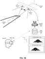
- FIG. 1A depicts a schematic of a system 100 for landing site localization, in accordance with one or more embodiments.
- the system 100 includes one or more flight data subsystems 110 coupled to (e.g., mounted to, onboard, within, etc.) an aircraft 105, a remote station 120 in communication with a data center 130 at a location remote from the aircraft 105, and an operator interface 140 in communication with the remote station 120 by way of the data center 130.
- the system 100 can also include a flight management system (FMS) 150 including interfaces between the remote station 120 to the FMS 150 and/or interfaces between the flight data subsystems 110 and the FMS 150.
- the system 100 provides structures, subsystem interfaces, and operation modes useful for implementation of automated flight operations, including operations associated with methods described in more detail in Section 2 below.
- the aircraft 105 shown in FIG. 1 is a fixed-wing aircraft.
- the aircraft has flight control surfaces for aerodynamically affecting flight of the aircraft relative to a pitch axis (i.e., a transverse axis), a yaw axis (i.e., a vertical axis), and a roll axis (i.e., longitudinal axis) of the aircraft.
- Flight control surfaces can include one or more of: ailerons, flaps, elevators, stabilizers (e.g., horizontal stabilizers), rudders, spoilers, slats, air brakes, vortex generators, trim surfaces, and any other suitable control surfaces.
- the aircraft also has a power plant for generation of mechanical power associated with flight operations, and in variations, the power plant can include one or more of: a piston engine (e.g., in-line engine, V-type engine, opposed engine, radial engine, etc.), a gas turbine engine (e.g., turbojet engine, turbofan engine), a pulse jet, a rocket, a Wankel engine, a Diesel engine, an electric engine, a hybrid engine, and any other suitable power plant system.
- the power plant is coupled to an energy source (e.g., fuel system, battery, solar cell, etc.) and a cooling system (e.g., forced convection cooling system, liquid cooling system, oil cooling system, etc.) for aircraft performance in flight.
- an energy source e.g., fuel system, battery, solar cell, etc.
- a cooling system e.g., forced convection cooling system, liquid cooling system, oil cooling system, etc.
- the flight data subsystems 110 include subsystems capable of generating data associated with dynamic states of the aircraft, environments about the aircraft, operation states of aircraft systems (e.g., power plant systems, energy systems, electrical systems, etc.), and any other suitable systems associated with operations of the aircraft on the ground or in flight.
- the flight data subsystems 110 also include subsystems capable of transmitting data to and from the aircraft 105 and other remote systems.
- the flight data subsystems 110 include subsystems that generate and receive information generated from subsystems coupled to the aircraft 105, as well as a flight computer 115 providing computational infrastructure (e.g., processing components, communication buses, memory, etc.) for communicating data between the subsystems.
- the flight computer 115 thus provides architecture for communication of data generated by subsystems, for communication with other systems remote from the aircraft 105, for control of subsystems, and/or for control of the aircraft.
- the flight data subsystems 110 can thus include specialized computer components designed for use in an aircraft, and in particular, can include components that are customized in configuration relative to each other and customized in relation to processing of signals received and processed to perform aspects of the methods described in Section 2 below.
- Flight management system 150 configured for automation of flight tasks in relation to a flight plan.
- the FMS 150 processes navigation database information (e.g., information associated with waypoints, airways, navigation aids, airports, runways, departure procedures, arrival procedures, holding patterns, etc.), aircraft subsystem statuses, and outputs of other subsystems (e.g., radar subsystems, sensor subsystems) and determines one or more desired flight paths based on the information.
- navigation database information e.g., information associated with waypoints, airways, navigation aids, airports, runways, departure procedures, arrival procedures, holding patterns, etc.
- other subsystems e.g., radar subsystems, sensor subsystems
- the FMS can cooperate with the flight computer 115 in receiving outputs of other subsystems of the flight data subsystems 110 and/or transmitting control instructions to affect operational states of other subsystems of the flight data subsystems 110.
- the FMS 150 can also include or interface with other control systems (e.g., of an autopilot) to transform calculated flight information into instructions for control of control surfaces of the aircraft 105 including one or more of: ailerons, flaps, elevators, stabilizers (e.g., horizontal stabilizers), rudders, spoilers, slats, air brakes, vortex generators, trim surfaces, and any other suitable control surfaces.
- the flight data subsystems 110 include a camera subsystem 111 mounted to the aircraft, where the camera subsystem 111 includes sensors configured to capture features of the landing site, features of objects in the vicinity of the landing site, features of calibration objects along a path of operation of the aircraft, features of other objects along a path of operation of the aircraft, and/or any other suitable object aspects to facilitate automated landing of the aircraft at a desired landing site.
- Sensors of the camera subsystem 111 can utilize the visible spectrum. Sensors of the camera subsystem 111 can additionally or alternatively include longwave infrared (LWIR) sensors (e.g., sensors operating in the 8-12 ⁇ m band).
- LWIR longwave infrared
- the camera subsystem 111 can also include optical elements (e.g., lenses, filters, mirrors, apertures etc.) for manipulating light reaching the sensors of the camera subsystem 111.
- the camera subsystem 111 can include one or more filters optically coupled to the sensors and configured to detect spectra of light emitted from airfield landing systems (e.g., lighting systems in accordance with Federal Aviation Administration Advisory Circular 150/5345-46E).
- Variations of the camera subsystem 111 can, however, have any other suitable sensor types and/or optical elements associated with visible spectra and/or non-visible spectra electromagnetic radiation.
- the camera subsystem 111 can have one or more cameras structurally mounted to the aircraft and positioned so as to enable detection of the landing site or other site relevant to operation of the aircraft, as the aircraft traverses through space. Multiple cameras can be used for system redundancy (e.g., in the event a subset of cameras have occluded optical elements) and/or for providing different field of view options depending on approach path and orientation to a landing site.
- the camera(s) of the camera subsystem 111 can be coupled to an interior portion of the aircraft 105, or can be coupled to an exterior portion of the aircraft 105. Mounting positions are associated with desired flight paths to a landing site (e.g., approach patterns, instructions from air traffic control, etc.).
- the camera subsystem 111 can have a camera that has a field of view of at least 270 degrees about the aircraft 105.
- the camera subsystem 111 can additionally or alternatively have a first camera mounted toward a port side of the aircraft (e.g., for left traffic operations), a second camera mounted toward a starboard side of the aircraft (e.g., for right traffic operations), a third camera mounted toward a nose portion of the aircraft (e.g., for straight-in approaches), and/or any other suitable cameras mounted at any other suitable portion of the aircraft 105.
- the camera(s) of the camera subsystem 111 can thus be fixed in position.
- the camera(s) of the camera subsystem 111 can alternatively be adjustable in position based on flight paths of the aircraft 105 to the landing site.
- the camera subsystem 111 can thus include actuators coupled to the camera(s) of the camera subsystem 111 and/or position encoders coupled to the actuators, in relation to electronic control of camera positions.
- the camera(s) of the camera subsystem 111 can be coupled to image stabilization subsystems (e.g., gimbals) to reduce artifacts due to vibration or other undesired image artifacts that would otherwise be included in image data generated from the camera subsystems 111.
- the camera subsystem 111 produces output images that have a characteristic resolution (e.g., associated with a sensor size), focal length, aspect ratio, and/or directionality (e.g., unidirectionality associated with 360 degree images), format color model, depth, and/or other aspects.
- the camera subsystem 111 can be configured for one or more of: monoscopic images, stereoscopic images, panoramic images, and/or any other suitable type of image output.
- the camera subsystem 111 can be configured to output video data, in relation to the method(s) described in Section 2 below.
- the camera subsystem 111 includes a first camera 111a mounted at a port side of the aircraft 105 and a second camera 111b mounted at a starboard side of the aircraft, where the first camera 111a and the second camera 111b collectively have modes for generation of stereoscopic images (e.g., left and right stereoscopic images associated with similar or identical time points of image capture). Stereoscopic images can then be transmitted to an operator wearing a head mounted display (HMD) 140b or otherwise interacting with a display of an operator interface for viewing stereoscopic images (e.g., in a 3D image format).
- HMD head mounted display
- the flight data subsystem 110 also includes one or more inertial measurement units (IMUs) 112 for measuring and outputting data associated with the aircraft's specific force, angular rate, magnetic field surrounding the aircraft 105, and/or other position, velocity, and acceleration-associated data. Outputs of the IMU can be processed with outputs of other aircraft subsystem outputs to determine poses of the aircraft 105 relative to a landing site (or other target), and/or pose trajectories of the aircraft 105 relative to a landing site (or other target).
- IMUs inertial measurement units
- the IMU 112 includes one or more accelerometers, one or more gyroscopes, and can include one or more magnetometers, where any or all of the accelerometer(s), gyroscope(s), and magnetometer(s) can be associated with a pitch axis, a yaw axis, and a roll axis of the aircraft 105.
- the IMUs 112 are coupled to the aircraft, and can be positioned internal to the aircraft or mounted to an exterior portion of the aircraft. In relation to measurement facilitation and/or post-processing of data form the IMU, the IMU can be coupled to a vibration dampener for mitigation of data artifacts from sources of vibration (e.g., engine vibration) or other undesired signal components.
- sources of vibration e.g., engine vibration
- the system 100 can include a radar subsystem that operates to detect radar responsive (e.g., reflective, scattering, absorbing, etc.) objects positioned relative to a flight path of the aircraft 105 (e.g., below the aircraft 105), in order to facilitate determination of pose or state of the aircraft 105 in supplementing methods described below.
- the system can include a light emitting subsystem that operates to detect light responsive (e.g., reflective, scattering, absorbing, etc.) objects positioned relative to a flight path of the aircraft 105 (e.g., below the aircraft 105), in order to facilitate determination of pose or state of the aircraft 105 in supplementing methods described below.
- the flight data subsystem 110 also includes a radio transmission subsystem 113 for communication with the aircraft 105, for transmission of aircraft identification information, or for transmission of other signals.
- the radio transmission subsystem 113 can include one or more multidirectional radios (e.g., bi-directional radios) onboard the aircraft, with antennas mounted to the aircraft in a manner that reduces signal transmission interference (e.g., through other structures of the aircraft).
- the radios of the radio transmission subsystem 113 operate in approved frequency bands (e.g., bands approved through Federal Communications Commission regulations, bands approved through Federal Aviation Administration advisory circulars, etc.).
- the flight data subsystem 110 can also include a satellite transmission subsystem 114 for interfacing with one or more satellites including satellite 14.
- the satellite transmission subsystem 114 transmits and/or receives satellite data for navigation purposes (e.g., on a scale associated with less precision than that used for landing at a landing site), for traffic avoidance in coordination with automatic dependent surveillance broadcast (ADS-B) functionality, for weather services (e.g., in relation to weather along flight path, in relation to winds aloft, in relation to wind on the ground, etc.), for flight information (e.g., associated with flight restrictions, for notices, etc.), and/or for any other suitable purpose.
- the satellite transmission subsystem 114 operates in approved frequency bands (e.g., bands approved through Federal Communications Commission regulations, bands approved through Federal Aviation Administration advisory circulars, etc.).
- the communication-related components of the flight data subsystems 110 can additionally or alternatively cooperate with or supplement data from other avionics components (e.g., a global positioning system and/or other localization subsystem 116), electrical components (e.g., lights), and/or sensors that support flight operations (e.g., in flight, during landing, on the ground, etc.), that support observability by other traffic, that support observability by other aircraft detection systems, that provide environmental information (e.g., pressure information, moisture information, visibility information, etc.) and/or perform other functions related to aircraft communications and observability.
- avionics components e.g., a global positioning system and/or other localization subsystem 116
- electrical components e.g., lights
- sensors that support flight operations (e.g., in flight, during landing, on the ground, etc.), that support observability by other traffic, that support observability by other aircraft detection systems, that provide environmental information (e.g., pressure information, moisture information, visibility information, etc.) and
- the system 100 also includes a remote station 120 that includes devices for wirelessly receiving data from and transmitting data to subsystems coupled to the aircraft.
- the remote station 120 includes one or more multidirectional radios (e.g., bi-directional radios) onboard the aircraft, with antennas mounted to the aircraft in a manner that reduces signal transmission interference (e.g., through other structures of the aircraft).
- the radios of the remote station operate in approved frequency bands (e.g., bands approved through Federal Communications Commission regulations, bands approved through Federal Aviation Administration advisory circulars, etc.).
- the remote station 120 is in communication with a data center 130 for storage and retrieval of data derived from subsystems of the aircraft 105 and/or outputs from the operator interface 140 described in more detail below.
- the data center uses storage and retrieval protocols and can use data encryption protocols for promoting security in relation to handling sensitive information pertaining to autonomous flight of the aircraft 105.
- the remote station 120 can also use communications technologies and/or protocols in relation to data transmission operations with the data center 130, subsystems of the aircraft 105, and/or the operator interface 140 described in more detail below.
- the remote station 120 can have communication links using technologies such as Ethernet, 802.11, worldwide interoperability for microwave access (WiMAX), 3G, 4G, code division multiple access (CDMA), digital subscriber line (DSL), or other communication technologies.
- technologies such as Ethernet, 802.11, worldwide interoperability for microwave access (WiMAX), 3G, 4G, code division multiple access (CDMA), digital subscriber line (DSL), or other communication technologies.
- Examples of networking protocols used for communications with the remote station 120 include user datagram protocol (UDP) and/or any other suitable protocol. Data exchanged with the remote station 120 can be represented using any suitable format.
- the aircraft 105 can be transitioned into a safety operation mode.
- the aircraft 105 enters a holding pattern until operation of the communications-related subsystems are restored to proper operation, or until the aircraft 105 can be operated safely/safely landed in another manner.
- the system 100 also includes an operator interface 140.
- the operator interface 140 receives processed data (e.g., image data) generated from the subsystems of the aircraft 105, provides representations of processed data to an operator or other entity (e.g., through a display), and receives inputs provided by the operator or other entity in response to provided representations of processed data.
- the operator interface 140 can include a conventional computer system, such as a desktop or laptop computer. Additionally or alternatively, the operator interface 140 can include a device having computer functionality, such as a personal digital assistant (PDA), a mobile telephone, a smartphone, a wearable computing device (e.g., a wrist-borne wearable computing device, a head-mounted wearable computing device, etc.), or another suitable device.
- PDA personal digital assistant
- the operator interface 140 is electronically coupled to the remote station 120 and/or the data center 130 by any combination of local area and/or wide area networks, using transmission and storage protocols, as described above, and can use both wired and/or wireless communication systems.
- the operator interface 140 can include a display for presentation of visually-observed digital content (e.g., images/videos from camera subsystem components of the aircraft 105), as shown in FIG. 1A .
- the operator interface can additionally or alternatively include a head mounted display 140b as shown in FIG. 1B for presentation of content to the operator, as described above.
- the operator interface 140 can include one or more of: a touch pad, a touch screen, a mouse, a joystick, an audio input device, an optical input device, and any other suitable input device for receiving inputs from the user.
- Portions of one or more of: the flight computer 115 onboard the aircraft 105, the FMS 150, the remote station 120, the data center 130, and the operator interface 140 can operate as a computing system that includes machine-readable instructions in non-transitory media for implementation of an embodiment of the method 200 described below, in relation to one or more of: transmitting an image taken from the camera subsystem 111 and capturing a landing site; receiving a reference position of a reference object associated with the landing site within the image; from the reference position, generating an image-estimated pose of the aircraft 105; updating a pose trajectory of the aircraft 105 upon processing the image-estimated pose and an output from the IMU 112 having a time stamp corresponding to the image; and based upon the pose trajectory, generating a set of instructions for flight control of the aircraft toward a flight path to the landing site (e.g., with the FMS 150, etc.).
- the system 100 can include an electronic interface between the remote station 110 and a flight management system of the aircraft (e.g., as supported by the computing system), the electronic interface operable in a mode that transmits the set of instructions to the flight management system and controls flight of the aircraft toward the flight path. Additional aspects of the method 200 are described in further detail in Section 2 below.
- system(s) described above can implement embodiments, variations, and/or examples of the method(s) described below, the system(s) can additionally or alternatively implement any other suitable method(s).
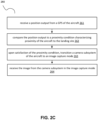
- FIG. 2A depicts a flowchart of a method 200 for landing site localization, in accordance with one or more embodiments.
- FIG. 2B depicts a schematics of a method flow according to embodiments shown in FIG. 2A .
- the method 200 functions to process sensor-derived data, transmit information between aircraft subsystems and systems remote from the aircraft, and dynamically generate updated estimates of position and orientation of the aircraft relative to a desired landing site, while the aircraft is in flight toward the desired landing site. Based on the position and orientation information, the method 200 can also generate instructions for flight control of the aircraft toward a flight path to the landing site, and can update flight control instructions as new data is received and processed.
- the method 200 can also include functionality for directly controlling flight of the aircraft toward the landing site in a reliable and safe manner.
- the method 200 can be implemented by one or more embodiments of the system 100 described above, in relation to FIGS. 1A and 1B .
- portions of the method 200 can be implemented by the computing system components described above, for instance, at a portion of the computing system operating at the remote station and/or at a portion of the computing system operating at a flight computer onboard the aircraft, with communication of inputs and outputs across computing system components as defined by the architecture described above.
- Blocks 210a and 210b include functionality for receiving an image taken from a camera subsystem coupled to an aircraft, where the image captures a landing site within a field of view of the camera subsystem.
- the remote station wirelessly receives one or more images taken from cameras of the camera subsystem coupled to the aircraft during flight of the aircraft in the vicinity of the landing site. Transmission of the images can occur through data transmission systems of the aircraft and remote station. The remote station and/or other computing system can then process the received image(s) according to subsequent blocks of the method.
- sensors of the camera subsystem involved in image capture can generate visible spectrum images and/or non-visible spectrum (e.g., LWIR) images.
- the camera subsystem can include and apply filtering (e.g., through filtering optical elements, through operations in software, etc.) to received image data to detect spectra of light emitted from airfield landing systems (e.g., lighting systems and/or markings in accordance with Federal Aviation Administration Advisory Circular 150/5345-46E, lighting systems and/or markings in accordance with International Civil Aviation Organization standards).
- the computing system can receive images generated from a port side of the aircraft, a starboard side of the aircraft, a belly region of the aircraft, and/or a nose-region of the aircraft for landing site localization.
- the computing system can receive images that have a characteristic resolution (e.g., associated with a sensor size), aspect ratio, and/or directionality (e.g., unidirectionality associated with 360 degree images), format color model, depth, and/or other aspects.
- the images can further include one or more of: monoscopic images, stereoscopic images, panoramic images, and/or any other suitable type of image.
- the computing system associated with Blocks 210a and 210b can receive video data and/or any other suitable type of data.
- FIG. 2C depicts a flowchart of a portion 260 of a method for landing site localization, in accordance with one or more embodiments, where the portion 260 of the method functions to trigger at least one of image capture and image transmission upon detection of a level of proximity between the aircraft and the landing site, as shown in FIG. 2A .
- the portion 260 of the method can reduce compute power (e.g., in relation to data processing and transmission, in relation to battery management requirements, etc.) that would otherwise be used to process images not capturing the landing site within a field of view.
- the computing system receives a position output from a global positioning system (GPS) of the aircraft.
- GPS global positioning system
- the position output can be derived from transmissions between a satellite and a GPS onboard the aircraft and describe a geographic distance between the aircraft and the landing site.
- the computing system e.g., navigation subsystems of the system
- the computing system can receive 261 position outputs derived from other distance measuring apparatus, such as a transponder-based distance measuring equipment (DME), a non-directional beacon (NDB), a lateral navigation (LNAV) system, a vertical navigation (VNAV) system, or an area navigation (RNAV) system.
- DME transponder-based distance measuring equipment
- NDB non-directional beacon
- LNAV lateral navigation
- VNAV vertical navigation
- RNAV area navigation
- a position output can be determined from dead reckoning using other sensors (e.g., IMU components, etc.), which can be beneficial in GPS-unavailable or GPS-denied scenarios.
- the computing system can receive position outputs in terms of geographic distances, line-of-sight-distances, or in any other suitable format.
- the landing site can be a paved runway (e.g., a runway in Class B airspace, a runway in Class C airspace, a runway in Class D airspace, a runway in other airspace), a landing strip (e.g., paved, grass, dirt), a water landing site, a landing site on snow, a landing site on sand, or any other landing site associated with an approach pattern and/or glide slope.
- the landing site can alternatively be a landing site associated with vertical takeoff and landing (VTOL) operations, such as those used by a helicopter or distributed electric propulsion (DEP) aircraft.
- VTOL vertical takeoff and landing
- DEP distributed electric propulsion
- the landing site can also have lighting systems and/or markings described in more detail below in Section 2.2.
- the computing system compares the position output to a proximity condition characterizing proximity of the aircraft to the landing site.
- the proximity condition is a threshold condition describing how close the aircraft is to the landing site (e.g., in terms of geographic distance, in terms of line-of-site distance, etc.). As such, a distance extracted from the position output is compared to a threshold distance.
- the proximity condition can be associated with a threshold distance of 15 miles from the landing site, 10 miles from the landing site, 5 miles from the landing site, or any other distance from the landing site.
- the threshold condition can additionally or alternatively be associated with entrance into airspace associated with the landing site, arrival at a position (e.g., 45 degree entry position, crosswind position, downwind position, base position, final position, etc.) associated with an approach path to the landing site.
- the threshold condition can additionally or alternatively be dynamically modified based on a speed of operation (e.g., cruise speed, approach speed, landing speed, etc.) of the aircraft, configuration of the aircraft (e.g., in terms of flap operation, spoiler operation, landing gear operation, etc.) and/or a weather condition (e.g., associated with winds, visibility, precipitation, etc.).
- a speed of operation e.g., cruise speed, approach speed, landing speed, etc.
- configuration of the aircraft e.g., in terms of flap operation, spoiler operation, landing gear operation, etc.
- a weather condition e.g., associated with winds, visibility, precipitation, etc.
- the threshold condition can be set to a greater distance threshold if the aircraft is
- the computing system determines if the proximity condition is met, and transitions a camera subsystem of the aircraft to an image capture mode.
- the computing system can determine if the distance of the aircraft to the landing site, extracted from the position output, is less than, equal to, or greater than the threshold distance, and then a remote station or other portion of the computing system can generate camera control instructions that are relayed to the camera subsystem through a camera control unit (e.g., portion of a flight computer) onboard the aircraft, in order to transition the camera subsystem to the image capture mode (or an image transmission mode).
- the remote station of the computing system can receive the image from the camera subsystem 264.
- the camera subsystem can be held in the image capture and/or transmission modes to transmit images at a desired frequency to the remote station.
- an onboard computing system can instruct camera subsystem 264 (or an image sensor system thereof) to capture an image using one or more different image capture modes, in order to maximize visibility of items of interest in the image.
- the system can take images corresponding to a range of exposure times, apertures, focal lengths, and/or any other suitable image-capture parameter.
- filtering if the camera subsystem 264 has selectable Bayer filters or other color filter arrays, color filtering can be applied during image capture as well.
- the selection criteria associated with different image capture modes can be chosen based upon one or more factors including: contrast information present in an image, time of day, sun ephemeris, moon ephemeris, weather conditions, airspeed, wind conditions, vibration conditions, and/or any other suitable geospatial/atmospheric information observable or known by the onboard computing system.
- Blocks 220a and 220b include functionality for determining a reference position of a reference object associated with the landing site.
- the computing system facilitates processing of the image(s) received from the camera subsystem of the aircraft at a location remote from the aircraft (e.g., at a remote station of the computing system), with manual input by a human entity and/or automatically through image processing and computer vision operations.
- the remote station of the computing system can determine a single position or multiple reference positions of a single reference object or multiple reference objects. As such, the relationships between the reference position(s) and the reference object(s) do not have to be one-to-one.
- the reference object(s) associated with Blocks 220a and 220b can include stationary objects.
- Stationary objects can include approach lighting systems (e.g., visual approach slope indicator lights, precision approach path indicator lights, other approach lights), runway lighting systems (e.g., lights associated with runway features, lights associated with clearances, lights associated with other air traffic control instructions), taxiway lighting systems (e.g., lights associated with taxiway features, lights associated with clearances, lights associated with other air traffic control instructions, etc.), beacons, other airport lights, and/or other non-airport lights in the vicinity of the landing site.
- Airport lighting objects can be regulated objects (e.g., according to International Civil Aviation Organization regulations).
- the reference object(s) associated with Blocks 220a and 220b can additionally or alternatively include airport markers associated with runway markings (e.g., centerlines, hold short bars, runway numbers, displaced thresholds, etc.), taxiway markings (e.g., centerlines, approach to hold short bars, instrument landing system position indicators, movement areas, non-movement areas, parking areas, etc.), airport signage, other airport markers, and/or other markers in the vicinity of the landing site.
- Airport markers can be regulated objects (e.g., according to International Civil Aviation Organization regulations).
- the reference object(s) associated with Blocks 220a and 220b can additionally or alternatively include large scale landing site objects (e.g., runways, taxiways, buildings, fields, transportation infrastructure, other infrastructure, geographic features, etc.), where edges, corners, or any other suitable feature of the objects can be detected and used as a landing site reference.
- large scale landing site objects e.g., runways, taxiways, buildings, fields, transportation infrastructure, other infrastructure, geographic features, etc.
- the remote station of the computing system can receive a packet from the entity, where the packet includes coordinates or other descriptors of the reference positions in space.
- outputs of Block 220a and 220b can characterize the position(s) of the reference object(s) associated with the landing site in a format that is computer machine-readable and able to be processed to produce additional outputs in downstream portions of the method.
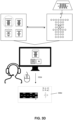
- FIG. 3A depicts a schematic of a variation of 220a and 220b, where the images(s) is/are transmitted to an entity at an operator interface, and upon selection of one or more positions of the reference objects(s) associated with the landing site captured in the images, the computing system receives packets characterizing the reference position(s) of the reference object(s).
- the computing system e.g., remote station in communication with a data center transmits the image to a display of the operator interface for observation by the entity at the operator interface.
- the entity can then select positions and/or boundary locations of the reference object(s), such as lighting at the landing site, or boundaries of a runway (e.g., positions of corners of a trapezoid defining corners of the runway, positions of points along a runway centerline, etc.) at the landing site.
- the computing system receives 320a packets containing coordinates of the locations of the reference object(s) upon selection of the coordinates by the entity through the operator interface.
- FIG. 3B depicts a schematic of another variation of 220a and 220b, where the images(s) is/are processed onboard automatically by the flight computer or transmitted to a remote computing entity that automatically applies image processing operations to the image(s) and outputs packets characterizing one or more positions of the reference objects(s) associated with the landing site captured in the images.
- Data packets can be stored in memory until used in downstream portions of the method.
- data packets can be transmitted remotely to the remote station for observation by a manual operator (as in the fully manual method) discussed previously.
- the computing system applies a filtering operation to the image to extract or otherwise increase the intensity of features of the reference object(s) captured in the image.
- the filtering operation can be a color filtering operation that isolates image pixels associated with a particular color (e.g., light wavelength, paint color, signage color, etc.) of the reference object to generate a color-filtered image.
- the filtering operation can also apply contrasting operations and/or saturation increasing operations to increase the contrast prior to or post application of a color filter.
- the filtering operation can also stack or aggregate multiple images in another manner in order to increase contrast.
- the computing system After application of the filtering operation, the computing system then applies a centroid algorithm to identify a center position of the reference objects, which in the image shown in FIG 3B include an array of light objects at the landing site.
- a centroid algorithm can omit application of a centroid algorithm and alternatively use another feature extraction approach (e.g., speeded up robust feature approach, oriented FAST and rotated BRIEF approach, scale invariant feature transform approach, etc.) locating a reference position of an object within an image.
- the computing system can also apply a transformation operation to transform the image (or filtered version thereof) from a 3D space to a 2D space, using a homography matrix operation, covariance matrix operation, or another transformation operation.
- the computing system can then automatically compare and match the centroid and/or extracted features of the transformed image to a database of airport lighting positions, including lighting positions at the landing site (e.g., using a random sample consensus operation, using an iterative closest point operation, etc.).
- transformations of the images can include scaling operations, perspective skewing operations, rotation operations, and/or any other suitable operations that transform inbound images to a form that maps onto a scale, perspective, rotation, or other format aspect of the images in the database of airport lighting positions.
- Matching can then be performed between transformed images that have analogous formats to the image formats in the database of airport lighting positions.
- Outputs of the transformation and matching processes are then used to generate data packets associated with coordinates of the locations of the reference objects (e.g., lights).
- the computing system receives 320b packets containing coordinates of the locations of the reference object(s) upon generation of the coordinates in an automated manner using image processing and matching operations.
- FIG. 3C depicts a schematic of an alternative variation to the variation of the portion of the method shown in FIG. 3B , where, in the alternative variation the computing system and/or remote computing entity omits application of a filtering operation to generate 320c the packet including the position(s) of the reference object(s).
- the computing system and/or remote computing entity can omit application of a transformation operation from 3D to 2D space in relation to comparing and matching images against a database of airport reference objects.
- FIG. 3D depicts a schematic of another variation of 220a and 220b, where the images(s) is/are transmitted to a remote computing entity that automatically applies image processing operations to the image(s), where the image processing operations can be similar to or identical to those performed in relation to FIGS. 3B and 3C .
- the remote computing entity can then transmit digital content derived from image processing to an entity at an operator interface.
- the entity at the operator interface can then verify the output of the remote computing entity, and upon verification by interaction with an input device of the operator interface, the computing system can receive packets characterizing one or more positions of the reference objects(s) associated with the landing site captured in the images.
- Blocks 230a and 230b include functionality for generating an image-estimated pose of the aircraft from outputs of Blocks 220a and 220b, respectively.
- the computing system e.g., a portion of the computing system operating at the remote station, a portion of the computing system operating at a flight computer onboard the aircraft
- receives the reference position(s) of the reference object(s) associated with the landing site and applies transformation processes to extract the image-estimated pose of the aircraft at the time that the image was taken.
- the reference position(s) can be transmitted to the computing system (or between portions of the computing system) with a unique identifier matching the image, such that reference positions can be associated with images and/or time stamps at which the images were taken.
- the computing system can receive coordinates of bounding corners of the runway within the image, and apply a transformation operation from a dimensional space associated with the image to a dimensional space associated with the camera or sensor from which the image was taken (e.g., using a homography matrix operation, using a covariance matrix operation, etc.).
- the transformation operation can include an image registration operation (e.g., registration with perspective projection, registration with orthogonal projection, etc.) to extract camera pose from the reference positions of the bounding corners of the runway.
- the computing system can perform a transformation operation from the dimensional space associated with the camera to the dimensional space associated with the pose of the aircraft to generate the image-estimated pose of the aircraft.
- Outputs of Blocks 230a and 230b can include, for each image processed, a position and orientation of the aircraft in 3D space, with global coordinates of the aircraft and rotations about axes of the aircraft.
- the computing system receives coordinates of a centroid of an array of airport lights.
- the computing system can additionally or alternatively receive parameters (e.g., matrix element coefficients) of a transformation process used in the comparing and matching operation of Blocks 320b, 320c, and 320d.
- the computing system can apply a transformation operation from a dimensional space associated with the centroid and/or database image to a dimensional space associated with the camera or sensor from which the image was taken (e.g., using a homography matrix operation, using a covariance matrix operation, etc.).
- the transformation operation can include an image registration operation (e.g., registration with perspective projection, registration with orthogonal projection, etc.) to extract camera pose from the reference positions. Then, the computing system can perform a transformation operation from the dimensional space associated with the camera to the dimensional space associated with the pose of the aircraft to generate 330b, 330c, 330d the image-estimated pose of the aircraft.
- Outputs of Blocks 330b-330d can include, for each image processed, a position and orientation of the aircraft in 3D space, with global coordinates of the aircraft and rotations about axes of the aircraft.
- the computing system can implement a calibration operation on the camera subsystem in order to generate image-estimated poses with a desired level of accuracy, and/or to inform decisions related to flight operations of the aircraft. For instance, an unsuccessful instance of the calibration operation can be used to transition the aircraft to a grounded status, thereby preventing flight of the aircraft until the reason for lack of success of the calibration operation is determined and resolved.
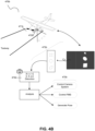
- FIG. 4A depicts an embodiment of a method 470a for camera subsystem calibration, in accordance with one or more embodiments
- FIG. 4B depicts a schematic of an embodiment of the method 470b shown in FIG. 4A .
- the methods shown in FIGS. 4A and 4B are used to precisely determine mounting positions and/or optical properties of camera subsystems used.
- the computing system (or other detection system onboard the aircraft) detects one or more marker objects near the aircraft using near-field communication methods, optical detection methods, methods based on geographic position of the aircraft, or any other suitable methods.
- the camera subsystem captures and transmits an image of the one or more marker objects near the aircraft (e.g., a path of motion of the aircraft, a parking position of the aircraft, etc.) and a computing system receives the image.
- the image is received and processed prior to takeoff of the aircraft (e.g., during a preflight inspection, during a taxiing operation of the aircraft), such that an informed flight decision can be made based on satisfactory calibration of the camera subsystem.
- variations of the methods 470a and 470b can additionally or alternatively perform instances of the calibration while the aircraft is in flight.
- the computing system Given known features (e.g., positions, shapes, colors, heights relative to the aircraft, heights relative to the camera subsystem, etc.) of the one or more marker objects, the computing system generates 473a, 473b an output analysis characterizing spatial configuration and operation of the camera subsystem upon processing a set of features of the marker object(s) extracted from the calibration image against a set of reference features of the marker object(s). Generating the output analysis can include generating 474a, 474b a camera position output, a camera orientation output, and a camera distortion output.
- the computing system can compare extracted features of the marker object(s) to one or more standard reference images of the marker objects. For instance, standard reference images can be images taken of the marker objects from different heights and/or orientations.
- generating the camera position output and the camera orientation output can include performing a transformation operation and/or matching operation from an image space associated with the calibration image to a reference space associated with the standard reference image(s), in order to extract the position and orientation of the camera used to take the calibration image.
- Generating the camera distortion output can include applying algorithms to determine distortion or other artifacts (e.g., noise) in the image, due to hardware (e.g., mounting issues, vibration issues) and/or software issues.
- control of the camera subsystem can include cleaning a sensor of the camera, adjusting a mounting position of the camera (e.g., through actuators and/or gimbals coupled to the camera), rebooting the camera, or re-performing the calibration operation due to an indeterminate result.
- control of the aircraft can include approving flight operations and providing instructions (e.g., to an FMS) that allow the aircraft to transition to a flight operation mode, or prohibiting flight operations (e.g., grounding the aircraft) and providing instructions that prevent the aircraft from transitioning to a flight operation mode.
- generating the image-estimated pose(s) of the aircraft can include generating the image-estimated pose(s) from the reference position(s) of the reference object(s) associated with the landing sight, and outputs of the calibration operation, based on known spatial orientation and operation parameters of the camera subsystem determined from the calibration operation.
- the computing system updates 240a, 240b a pose trajectory (e.g., time series of poses) of the aircraft using measurements taken from one or more IMUs onboard the aircraft.
- Blocks 240a and 240b thus function to, based on the recent image data from the aircraft taken during flight to the landing site, generate and update a pose trajectory of the aircraft, by combining image data of the landing site with IMU outputs.
- updating of pose estimates based on image-derived information can be used to mitigate drift in propagation of poses generated by dead-reckoning with IMU measurements.
- the IMU output can include a position value (e.g., associated with a global reference frame), a velocity value, an orientation value, and a time stamp.
- IMU outputs can additionally include an altitude value, an angular rate value, and any other value of a parameter derived from acceleration or angular rate data.
- the image-estimated poses can be processed with IMU outputs to determine or update pose values of the aircraft relative to the landing site, as opposed to another reference.
- the pose trajectory includes aircraft poses (e.g., coordinates in Cartesian space with rotational coordinates about rotational axes) associated with time stamps of images taken by the camera subsystem.
- the pose trajectory also includes aircraft poses associated with time stamps of IMU outputs (e.g., in relation to a buffer or data stream of IMU outputs).
- the pose trajectory can also include aircraft poses interpolated between time points of images and/or IMU outputs.
- the pose trajectory can also include poses extrapolated or projected to time points beyond time stamps associated with images and/or IMU outputs.
- Blocks 240a and 240b can include functionality for adjusting or correct past poses associated with time points prior to a current state of the aircraft, time points associated with a current state of the aircraft, and/or time points projected to times beyond a current state of the aircraft.
- the computing system processes an image-estimated pose having a time stamp with an IMU output having the same or a similar (e.g., nearest) time stamp to compute an updated pose of the aircraft relative to the a location of the landing site.
- Computing the updated pose can include performing a vector, array, or matrix manipulation process (e.g., transformation, addition, etc.) to combine information from an IMU output with information from the image-estimated pose.
- a vector, array, or matrix manipulation process e.g., transformation, addition, etc.
- the associated image-estimated pose components can be used to replace components of the matching IMU-based pose estimate.
- the computing system can then apply a forward propagation operation to IMU data (e.g., IMU data having time stamps unassociated with images, IMU data having time stamps associated with images) until another image-estimated pose is processed, thereby updating the pose trajectory with information computed from the image-estimated pose.
- IMU data e.g., IMU data having time stamps unassociated with images, IMU data having time stamps associated with images
- image-estimated pose components can be averaged with IMU measurements across a window of time associated with the image-estimated pose, and forward propagation with the averaging process can be performed until another image-estimated pose is processed.
- the method 200 can include functionality for controlling flight of the aircraft toward a flight path to the landing site.
- the computing system e.g., a portion of the computing system operating at the remote station, a portion of the computing system operating at a flight computer onboard the aircraft, etc.
- the computing system generates 250a, 250b instructions for flight control of the aircraft to the landing site.
- the flight computer or other computing components controlling operation of flight control surfaces receive the instructions and control operational configurations of one or more control surfaces of the aircraft to maintain or redirect flight of the aircraft toward the landing site.
- blocks 250a and 250b include functionality for controlling flight of the aircraft toward the flight path upon transmitting the set of instructions to a flight computer of the aircraft and manipulating one or more flight control surfaces of the aircraft based on the set of instructions.
- the computing system can use generated instructions to control configuration states of one or more of: ailerons of the aircraft (e.g., to affect flight about a roll axis), flaps of the aircraft (e.g., to affect rate of descent), elevators of the aircraft (e.g., to control flight about a pitch axis), rudders of the aircraft (e.g., to control flight about a yaw axis), spoilers of the aircraft (e.g., to control lift of the aircraft), slats of the aircraft (e.g., to control angle of attack of the aircraft), air brakes (e.g., to control drag of the aircraft), trim surfaces (e.g., to control trim of the aircraft relative to any axis and/or reduce system mechanical load), and any other suitable control surfaces of the aircraft.
- ailerons of the aircraft e.g., to affect flight about a roll axis
- flaps of the aircraft e.g., to affect rate of descent
- elevators of the aircraft e
- the computing system e.g., the flight computer
- configuration states of power plant components including one or more of: manifold pressure, revolutions (e.g., revolutions per minute), fuel mixture, electrical output from a battery, cooling system operational states (e.g., in relation to cowl flaps, in relation to liquid cooling systems, in relation to fins, etc..) for aircraft performance toward the landing site.
- the computing system e.g., the flight computer
- the computing system can also use generated instructions to control other aircraft system aspects.
- the generated instructions can be used to control communications with air traffic control at the landing site, in relation to automated reception and/or read back of instructions from air traffic control.
- the computing system In relation to pose or pose trajectory of the aircraft, the computing system generates instructions that account for aircraft orientation due to environmental effects and landing procedures due to environmental effects. For instance, the computing system can generate instructions upon detecting crosswinds and computing a crosswind control factor for the ailerons and rudders of the aircraft. In another example, computing system can generate instructions for a flight path to a preferred runway due to prevailing winds at the landing site (e.g., to avoid landing with a significant tail wind). In another example, the computing system can generate instructions for power plant settings in relation to winds at the landing site.
- the computing system can also generate instructions that account for landing site features and/or geographical features about the landing site. For instance, the computing system can generate instructions for producing a steeper or flatter approach (e.g., with slipped configuration settings, with flap settings, with landing gear settings, etc.) based on runway features (e.g., length, position relative to geography, position relative to obstacles along the approach path, etc.). In another example, the computing system can generate instructions for control surface settings and/or power plant settings based on runway features, such as uphill grade, downhill grade, roughness, wetness, type (e.g., grass, dirt, water, snow, etc.), width, and/or any other suitable landing site feature. In another example, the computing system can generate instructions for control of the aircraft and/or verification of appropriate pose relative to a desired runway, which can be beneficial if there are multiple parallel runways and/or taxiways about the desired runway for landing.
- runway features e.g., length, position relative to geography, position relative to obstacles along the approach path, etc.
- the computing system
- the computing system can also generate instructions that account for type of landing gear of the aircraft. For instance, the computing system can generate instructions to maintain orientation for a three-point landing for an aircraft with a conventional landing gear configuration (e.g., tailwheel). In another example, the computing system can generate instructions to adjust orientation for a wheel landing for an aircraft with a conventional landing gear configuration. In another example, the computing system can generate instructions to adjust orientation for an aircraft with a tricycle gear setting. In another example, the computing system can generate instructions to adjust orientation for an aircraft with a crosswind landing gear.
- a conventional landing gear configuration e.g., tailwheel
- the computing system can generate instructions to adjust orientation for a wheel landing for an aircraft with a conventional landing gear configuration.
- the computing system can generate instructions to adjust orientation for an aircraft with a tricycle gear setting.
- the computing system can generate instructions to adjust orientation for an aircraft with a crosswind landing gear.
- the computing system can generate instructions used by the flight computer to control aircraft operation for other aircraft aspects, other environmental aspects, and/or other landing site aspects.
- the method can optionally include functionality for using an image-estimated pose, pose trajectory, or other method output to perform a system check.
- FIG. 5 depicts a method for performing a system check, in accordance with one or more embodiments.
- the computing system e.g., portion at a remote station, portion onboard the aircraft
- the computing system can compare a position component of a pose of the aircraft associated with a given time stamp to a position of the aircraft determined from a GPS output at the given time stamp. The comparison can be used to determine if the image-derived position is significantly different from the GPS-derived position.
- Aircraft control instructions can include various instructions described in Section 2.5 above, or any other suitable instructions.
- Navigation system control instructions can include instructions for rebooting a navigation system, transitioning a navigation system to a deactivated or idle state, preventing a navigation system from controlling other aircraft subsystems (e.g., an autopilot system), and/or any other suitable navigation system control instructions.
- the method and associated system components can include functionality for supporting a pilot operating the aircraft.
- the method and/or system can operate in a co-pilot operation mode where any generated analyses of pose, analyses of pose trajectory, and/or instructions are transformed into notifications to the pilot (e.g., at a display, through an audio output device, etc.) in relation to suggestions for control of the aircraft.
- Notifications can include a notification to abort landing (if landing is deemed to be unsafe), a notification that indicates that the approach to the landing site is appropriate, a notification related to changes to course of the aircraft (e.g., relative to the landing site), a notification related to configuration of the aircraft in relation to approach to the landing site, and/or any other suitable notification.
- the method(s) described can, however, include any other suitable steps or functionality for determining aircraft poses while the aircraft is in flight, controlling flight operation of the aircraft (e.g., toward a landing site), and/or evaluating performance of subsystems of the aircraft based on computed pose information.
- the system and methods described can confer benefits and/or technological improvements, several of which are described herein.
- the system and method employ non-traditional use of sensors (e.g., image sensors, IMUs, etc.) to determine poses of an aircraft while the aircraft is in flight toward a landing site.
- Landing an aircraft in particular, requires dynamic monitoring and control of aircraft operational states, and the method and system employ sensors in a novel manner for control of flight of aircraft (e.g., fixed wing aircraft, other aircraft) in relation to landing.
- the system and method also reduces computing requirements and costs associated with standard systems for guided landing. For instance, by using images taken at a set of time points and IMU data, the system achieves determination of aircraft pose and control of aircraft flight operation with less data and computing power than other systems for automated landing.
- the system and method also include functionality for evaluating performance of other subsystems of the aircraft (e.g., image capture subsystems, navigation systems, etc.) to improve their performance or otherwise improve safety of a flight operation.
- other subsystems of the aircraft e.g., image capture subsystems, navigation systems, etc.
- a software module is implemented with a computer program product comprising a computer-readable medium containing computer program code, which can be executed by a computer processor for performing any or all of the steps, operations, or processes described.
- Embodiments may also relate to an apparatus for performing the operations herein.
- This apparatus may be specially constructed for the required purposes, and/or it may comprise a general-purpose computing device selectively activated or reconfigured by a computer program stored in the computer.
- a computer program may be stored in a non-transitory, tangible computer readable storage medium, or any type of media suitable for storing electronic instructions, which may be coupled to a computer system bus.
- any computing systems referred to in the specification may include a single processor or may be architectures employing multiple processor designs for increased computing capability.
- Embodiments may also relate to a product that is produced by a computing process described herein.
- a product may comprise information resulting from a computing process, where the information is stored on a non-transitory, tangible computer readable storage medium and may include any embodiment of a computer program product or other data combination described herein.
Landscapes
- Engineering & Computer Science (AREA)
- Radar, Positioning & Navigation (AREA)
- Remote Sensing (AREA)
- Aviation & Aerospace Engineering (AREA)
- Physics & Mathematics (AREA)
- General Physics & Mathematics (AREA)
- Automation & Control Theory (AREA)
- Multimedia (AREA)
- Signal Processing (AREA)
- Traffic Control Systems (AREA)
Claims (15)
- Verfahren zur Landestellenlokalisierung, wobei das Verfahren Folgendes umfasst:Empfangen eines Bildes, das eine Landestelle von einem Sichtfeld eines Luftfahrzeugs aus erfasst, wobei das Bild einen zugehörigen Zeitstempel aufweist;Bestimmen einer Referenzposition eines Referenzobjekts, das zu der Landestelle gehört;Erzeugen einer aus dem Bild geschätzten Stellung des Luftfahrzeugs aus der Referenzposition;Abgleichen der aus dem Bild geschätzten Stellung mit einer ersten Ausgabe einer Trägheitsmesseinheit, IMU, die einen Zeitstempel aufweist, welcher dem zum Bild gehörigen Zeitstempel am nächsten liegt;Aktualisieren einer Stellungstrajektorie des Luftfahrzeugs durch Vorwärtsübertragen von Komponenten der aus dem Bild geschätzten Stellung auf einen Satz von IMU-Ausgaben, die nach der ersten IMU-Ausgabe erzeugt werden; undErzeugen eines Satzes computerlesbarer Anweisungen zur Flugsteuerung des Luftfahrzeugs zu einer Flugbahn zur Landestelle hin, basierend auf der aktualisierten Stellungstrajektorie.
- Verfahren nach Anspruch 1, wobei die erste Ausgabe der Trägheitsmesseinheit, IMU, eine von einer Vielzahl von IMU-Ausgaben einer IMU ist, die aus einer IMU stammen, die mit dem Luftfahrzeug gekoppelt ist.
- Verfahren nach Anspruch 1 oder 2, wobei:das Bild in Reaktion auf das Erkennen empfangen wird, dass sich das Luftfahrzeug innerhalb eines Näheschwellenwertes zu der Landestelle befindet, wobei das Bild aus einem Kamerateilsystem aufgenommen wird, das an das Luftfahrzeug gekoppelt ist;das Bild an eine Entität fern dem Luftfahrzeug übertragen wird; unddas Bestimmen der Referenzposition des Referenzobjekts das Empfangen eines Pakets von der Entität umfasst, das die Referenzposition des Referenzobjekts kennzeichnet.
- Verfahren nach Anspruch 3, wobei das Empfangen des Pakets das Empfangen eines Satzes von Koordinatenelementen umfasst, die durch eine Eingangsvorrichtung ausgewählt werden, welche der Entität zugeordnet ist, wobei der Satz von Koordinatenelementen einer Begrenzung des Referenzobjekts entspricht.
- Verfahren nach einem der Ansprüche 1 bis 3, wobei das Erzeugen der aus dem Bild geschätzten Stellung Folgendes umfasst:Erzeugen eines umgewandelten Bildes beim Umwandeln des Bildes aus einem ersten dimensionalen Raum in einen zweiten dimensionalen Raum; undErzeugen der aus dem Bild geschätzten Stellung beim Durchführen eines Abgleichvorgangs mit dem umgewandelten Bild und einem Satz von Bildern von Kandidatenreferenzobjekten.
- Verfahren nach Anspruch 5, umfassend das Erzeugen eines farbgefilterten Bildes beim Verarbeiten des Bildes mit einem Farbfilter, der einem Farbmerkmal des Referenzobjekts entspricht,
wobei das Erzeugen des umgewandelten Bildes Folgendes umfasst:Erzeugen eines umgewandelten Bildes beim Umwandeln des farbgefilterten Bildes aus einem ersten dimensionalen Raum in einem zweiten dimensionalen Raum;wobei das Erzeugen der aus dem Bild geschätzten Stellung Folgendes umfasst:Extrahieren der Referenzposition aus dem umgewandelten Bild; undErzeugen der aus dem Bild geschätzten Stellung beim Verarbeiten der Referenzposition, des umgewandelten Bildes und des Satzes von Bildern von Referenzobjekten mit dem Abgleichvorgang hin. - Verfahren nach einem der Ansprüche 1 bis 3, wobei das Referenzobjekt mindestens eines von einer Landestellenbegrenzung, einem Muster von Landestellenmarkierungen und einem Satz von Landestellenleuchten umfasst.
- Verfahren nach einem der Ansprüche 1 bis 3, wobei das Abgleichen der Stellungstrajektorie das Ersetzen von Komponenten der IMU-Ausgabe durch Komponenten der aus dem Bild geschätzten Stellung umfasst.
- Verfahren nach einem der Ansprüche 1 bis 3, wobei das Empfangen des Bildes das Empfangen eines Langwellen-Infrarot-, LWIR-, Bildes umfasst.
- Verfahren nach Anspruch 3, wobei das Kamerateilsystem Folgendes umfasst:eine erste Kamera, die an eine Backbordseite des Luftfahrzeugs montiert ist, und eine zweite Kamera, die an eine Steuerbordseite des Luftfahrzeugs montiert ist,wobei das Bild ein Paar stereoskopischer Bilder umfasst; undwobei das Empfangen des Pakets, das die Referenzposition kennzeichnet, das Übertragen des Paares stereoskopischer Bilder an die Entität durch eine Benutzerschnittstellen-Vorrichtung, welche eine Anzeige umfasst, und das Empfangen einer Auswahl eines Begrenzungsmerkmals entsprechend der Referenzposition durch die Benutzerschnittstellen-Vorrichtung umfasst.
- Verfahren nach einem der Ansprüche 1 bis 3, ferner umfassend das Steuern des Fluges des Luftfahrzeugs hin zu der Flugbahn beim Übertragen des Satzes von Anweisungen an einen Flugcomputer des Luftfahrzeugs und das Handhaben einer Flugsteuerungsoberfläche des Luftfahrzeugs basierend auf dem Satz von Anweisungen.
- Verfahren nach einem der Ansprüche 1 bis 3, wobei das Empfangen des Bildes Folgendes umfasst:Empfangen einer Positionsausgabe von einem GPS, Global Positioning System, des Luftfahrzeugs;Vergleichen der Positionsausgabe mit einer Nähebedingung, die eine Nähe des Luftfahrzeugs zur Landestelle kennzeichnet;Überleiten eines Kamerateilsystems des Luftfahrzeugs in einen Bilderfassungsmodus auf das Erfüllen der Nähebedingung hin; undEmpfangen des Bildes von dem Kamerateilsystem in dem Bilderfassungsmodus.
- System zur Landestellenlokalisierung, wobei das System Folgendes umfasst:ein Kamerateilsystem, das mit einem Sichtfeld auf eine Flugbahn des Luftfahrzeugs an ein Luftfahrzeug montiert ist;eine Trägheitsmesseinheit, IMU, die an das Luftfahrzeug montiert ist;ein Datenübertragungs-Teilsystem in Kommunikation mit dem Kamerateilsystem und der IMU; undein Rechensystem, das maschinenlesbare Anweisungen in nicht-flüchtigen Medien umfasst, die bei Ausführung durch einen Computer den Computer veranlassen werden, ein Verfahren nach einem der vorhergehenden Ansprüche auszuführen.
- System nach Anspruch 13, wobei das Kamerateilsystem eine erste Kamera umfasst, die an eine Backbordseite des Luftfahrzeugs montiert ist, und eine zweite Kamera, die an eine Steuerbordseite des Luftfahrzeugs montiert ist, wobei das Bild ein Paar stereoskopischer Bilder umfasst und wobei das Rechensystem Anweisungen zum Erzeugen der aus dem Bild geschätzten Stellung des Luftfahrzeugs aus dem stereoskopischen Bild umfasst.
- System nach Anspruch 13, ferner umfassend eine elektronische Schnittstelle zwischen dem Rechensystem und einem Flugcomputer des Luftfahrzeugs, wobei der Flugcomputer an Betriebskonfigurationen von Steuerungsoberflächen des Luftfahrzeugs gekoppelt ist und diesen steuert und die elektronische Schnittstelle in einem Modus betreibbar ist, der den Satz von Anweisungen an den Flugcomputer überträgt und den Flug des Luftfahrzeugs hin zu der Flugbahn steuert.
Applications Claiming Priority (2)
| Application Number | Priority Date | Filing Date | Title |
|---|---|---|---|
| US16/057,704 US10935987B2 (en) | 2018-08-07 | 2018-08-07 | Landing site localization for dynamic control of an aircraft toward a landing site |
| PCT/US2019/041258 WO2020033099A1 (en) | 2018-08-07 | 2019-07-10 | Landing site localization for dynamic control of an aircraft toward a landing site |
Publications (3)
| Publication Number | Publication Date |
|---|---|
| EP3833600A1 EP3833600A1 (de) | 2021-06-16 |
| EP3833600A4 EP3833600A4 (de) | 2022-05-04 |
| EP3833600B1 true EP3833600B1 (de) | 2025-04-02 |
Family
ID=69406007
Family Applications (1)
| Application Number | Title | Priority Date | Filing Date |
|---|---|---|---|
| EP19847135.1A Active EP3833600B1 (de) | 2018-08-07 | 2019-07-10 | Landestellenlokalisierung zur dynamischen steuerung eines flugzeugs zu einer landestelle |
Country Status (3)
| Country | Link |
|---|---|
| US (1) | US10935987B2 (de) |
| EP (1) | EP3833600B1 (de) |
| WO (1) | WO2020033099A1 (de) |
Families Citing this family (17)
| Publication number | Priority date | Publication date | Assignee | Title |
|---|---|---|---|---|
| EP3934127B1 (de) * | 2018-10-12 | 2024-05-29 | OQ Technology S.à r.l. | Verfahren und system für nichtterrestrische zellulare drahtlose kommunikationsnetze |
| US11532237B2 (en) * | 2019-02-28 | 2022-12-20 | Rockwell Collins, Inc. | Autonomous aircraft sensor-based positioning and navigation system using markers |
| CN111746816B (zh) * | 2020-05-18 | 2022-03-08 | 陈穗 | 一种飞机降落辅助装置及降落方法 |
| CN112093034A (zh) * | 2020-09-22 | 2020-12-18 | 青海奥珞威信息科技有限公司 | 一种旋翼磁动力无人机起落架收放系统 |
| US11760472B2 (en) * | 2020-12-01 | 2023-09-19 | Textron Innovations Inc. | Rudders for rotorcraft yaw control systems |
| US12148183B2 (en) * | 2020-12-18 | 2024-11-19 | The Boeing Company | Determining a current pose estimate of an aircraft relative to a runway to support the aircraft on approach |
| US11628745B2 (en) | 2021-02-05 | 2023-04-18 | Beta Air, Llc | Apparatus for a ground-based battery management for an electric aircraft |
| WO2022216370A1 (en) * | 2021-02-17 | 2022-10-13 | Merlin Labs, Inc. | Method for aircraft localization and control |
| AU2022380638B2 (en) * | 2021-08-19 | 2024-11-28 | Merlin Labs, Inc. | Advanced flight processing system and/or method |
| US11875034B2 (en) * | 2021-09-27 | 2024-01-16 | Honeywell International Inc. | Systems and methods for flight deck customization and pilot performance analytics |
| CN114239745B (zh) * | 2021-12-22 | 2022-06-17 | 中国民航科学技术研究院 | 一种机场航班起降与跑道运行状态自动识别方法 |
| CN114527800B (zh) * | 2022-02-25 | 2025-03-04 | 广州极飞科技股份有限公司 | 一种无人机降落场选取方法、装置、系统及可读存储介质 |
| FR3139654B1 (fr) * | 2022-09-13 | 2025-02-21 | Safran Electronics & Defense | Procédé et dispositif de navigation pour un aéronef, système, aéronef, programme d'ordinateur et support d'informations associés |
| US12197236B2 (en) | 2022-10-20 | 2025-01-14 | Saudi Arabian Oil Company | System, apparatus, and method for providing augmented reality assistance to wayfinding and precision landing controls of an unmanned aerial vehicle to differently oriented inspection targets |
| US11972039B1 (en) * | 2022-12-02 | 2024-04-30 | ARMaps | Augmented reality skydiving system |
| CN116189480B (zh) * | 2022-12-20 | 2023-08-18 | 中国民航科学技术研究院 | 一种航班复飞动作自动识别方法 |
| US12525131B2 (en) * | 2023-03-29 | 2026-01-13 | Rockwell Collins, Inc. | Ground air traffic monitoring under low visibility conditions using augmented reality (using head-mounted display) |
Citations (1)
| Publication number | Priority date | Publication date | Assignee | Title |
|---|---|---|---|---|
| US20160122038A1 (en) * | 2014-02-25 | 2016-05-05 | Singularity University | Optically assisted landing of autonomous unmanned aircraft |
Family Cites Families (10)
| Publication number | Priority date | Publication date | Assignee | Title |
|---|---|---|---|---|
| US8019490B2 (en) | 2006-09-29 | 2011-09-13 | Applied Minds, Llc | Imaging and display system to aid helicopter landings in brownout conditions |
| JP5690539B2 (ja) * | 2010-09-28 | 2015-03-25 | 株式会社トプコン | 自動離着陸システム |
| FR3009117B1 (fr) * | 2013-07-24 | 2016-11-25 | Airbus Operations Sas | Procede et systeme d'atterrissage automatique autonome |
| ES2850149T3 (es) | 2014-12-31 | 2021-08-25 | Sz Dji Technology Co Ltd | Restricciones y control de altitud del vehículo |
| US20160335901A1 (en) * | 2015-04-07 | 2016-11-17 | Near Earth Autonomy, Inc. | Control of autonomous rotorcraft in limited communication environments |
| US10586464B2 (en) | 2015-07-29 | 2020-03-10 | Warren F. LeBlanc | Unmanned aerial vehicles |
| US9963246B2 (en) * | 2016-03-28 | 2018-05-08 | Amazon Technologies, Inc. | Combining depth and thermal information for object detection and avoidance |
| US10782411B2 (en) * | 2018-01-12 | 2020-09-22 | Uatc, Llc | Vehicle pose system |
| JP7143444B2 (ja) * | 2018-02-09 | 2022-09-28 | スカイディオ,インコーポレイテッド | 航空機のスマート着陸 |
| US10532825B2 (en) * | 2018-05-07 | 2020-01-14 | The Boeing Company | Sensor-based guidance for rotorcraft |
-
2018
- 2018-08-07 US US16/057,704 patent/US10935987B2/en active Active - Reinstated
-
2019
- 2019-07-10 WO PCT/US2019/041258 patent/WO2020033099A1/en not_active Ceased
- 2019-07-10 EP EP19847135.1A patent/EP3833600B1/de active Active
Patent Citations (1)
| Publication number | Priority date | Publication date | Assignee | Title |
|---|---|---|---|---|
| US20160122038A1 (en) * | 2014-02-25 | 2016-05-05 | Singularity University | Optically assisted landing of autonomous unmanned aircraft |
Also Published As
| Publication number | Publication date |
|---|---|
| WO2020033099A1 (en) | 2020-02-13 |
| US20200050217A1 (en) | 2020-02-13 |
| US10935987B2 (en) | 2021-03-02 |
| EP3833600A1 (de) | 2021-06-16 |
| EP3833600A4 (de) | 2022-05-04 |
Similar Documents
| Publication | Publication Date | Title |
|---|---|---|
| US11749126B2 (en) | Landing site localization for dynamic control of an aircraft toward a landing site | |
| EP3833600B1 (de) | Landestellenlokalisierung zur dynamischen steuerung eines flugzeugs zu einer landestelle | |
| US12498718B2 (en) | Landing site localization for dynamic control of an aircraft toward a landing site | |
| US20240321124A1 (en) | Cross-checking localization during aircraft terminal operations | |
| US11763687B2 (en) | Survey-augmented navigation system for an aircraft | |
| US10332409B2 (en) | Midair collision threat detection and assessment using visual information | |
| CN107924196B (zh) | 用于自动辅助航空器着陆的方法 | |
| US7818127B1 (en) | Collision avoidance for vehicle control systems | |
| US10051178B2 (en) | Imaging method and appartus | |
| KR101494654B1 (ko) | 무인항공기 착륙유도 방법 및 장치와 착륙제어 방법 및 장치 | |
| US12315268B2 (en) | Vision-based landing system | |
| RU2703412C2 (ru) | Способ обеспечения автоматической посадки летательного аппарата | |
| EP3077760B1 (de) | Nutzlastanlieferung | |
| US10203691B2 (en) | Imaging method and apparatus | |
| CN113295164B (zh) | 一种基于机场跑道的无人机视觉定位方法及装置 | |
| Huh et al. | A vision-based landing system for small unmanned aerial vehicles using an airbag | |
| CN114689030A (zh) | 一种基于机载视觉的无人机辅助定位方法及系统 | |
| CN112797982A (zh) | 一种基于机器视觉的无人机自主着陆测量方法 | |
| US20260072448A1 (en) | Landing Site Localization for Dynamic Control of an Aircraft Toward a Landing Site | |
| US20240094726A1 (en) | Verifying flight system calibration and performing automated navigation actions | |
| GB2522328A (en) | Payload delivery | |
| Moutinho et al. | Project DIVA: Guidance and vision surveillance techniques for an autonomous airship | |
| Hecker et al. | Integrity Enhancement of an Integrated Navigation System with Optical Sensors | |
| Esin | Vision-aided landing for fixed wing unmanned aerial vehicle |
Legal Events
| Date | Code | Title | Description |
|---|---|---|---|
| STAA | Information on the status of an ep patent application or granted ep patent |
Free format text: STATUS: THE INTERNATIONAL PUBLICATION HAS BEEN MADE |
|
| PUAI | Public reference made under article 153(3) epc to a published international application that has entered the european phase |
Free format text: ORIGINAL CODE: 0009012 |
|
| STAA | Information on the status of an ep patent application or granted ep patent |
Free format text: STATUS: REQUEST FOR EXAMINATION WAS MADE |
|
| 17P | Request for examination filed |
Effective date: 20210226 |
|
| AK | Designated contracting states |
Kind code of ref document: A1 Designated state(s): AL AT BE BG CH CY CZ DE DK EE ES FI FR GB GR HR HU IE IS IT LI LT LU LV MC MK MT NL NO PL PT RO RS SE SI SK SM TR |
|
| DAV | Request for validation of the european patent (deleted) | ||
| DAX | Request for extension of the european patent (deleted) | ||
| A4 | Supplementary search report drawn up and despatched |
Effective date: 20220407 |
|
| RIC1 | Information provided on ipc code assigned before grant |
Ipc: G05D 1/04 20060101ALI20220401BHEP Ipc: B64D 47/04 20060101AFI20220401BHEP |
|
| REG | Reference to a national code |
Ref country code: DE Ref legal event code: R079 Free format text: PREVIOUS MAIN CLASS: B64D0047040000 Ipc: G05D0001000000 Ref document number: 602019068209 Country of ref document: DE |
|
| GRAP | Despatch of communication of intention to grant a patent |
Free format text: ORIGINAL CODE: EPIDOSNIGR1 |
|
| STAA | Information on the status of an ep patent application or granted ep patent |
Free format text: STATUS: GRANT OF PATENT IS INTENDED |
|
| RIC1 | Information provided on ipc code assigned before grant |
Ipc: G05D 1/00 20060101AFI20240522BHEP |
|
| INTG | Intention to grant announced |
Effective date: 20240605 |
|
| GRAJ | Information related to disapproval of communication of intention to grant by the applicant or resumption of examination proceedings by the epo deleted |
Free format text: ORIGINAL CODE: EPIDOSDIGR1 |
|
| STAA | Information on the status of an ep patent application or granted ep patent |
Free format text: STATUS: REQUEST FOR EXAMINATION WAS MADE |
|
| GRAP | Despatch of communication of intention to grant a patent |
Free format text: ORIGINAL CODE: EPIDOSNIGR1 |
|
| STAA | Information on the status of an ep patent application or granted ep patent |
Free format text: STATUS: GRANT OF PATENT IS INTENDED |
|
| INTC | Intention to grant announced (deleted) | ||
| INTG | Intention to grant announced |
Effective date: 20241023 |
|
| GRAS | Grant fee paid |
Free format text: ORIGINAL CODE: EPIDOSNIGR3 |
|
| GRAA | (expected) grant |
Free format text: ORIGINAL CODE: 0009210 |
|
| STAA | Information on the status of an ep patent application or granted ep patent |
Free format text: STATUS: THE PATENT HAS BEEN GRANTED |
|
| AK | Designated contracting states |
Kind code of ref document: B1 Designated state(s): AL AT BE BG CH CY CZ DE DK EE ES FI FR GB GR HR HU IE IS IT LI LT LU LV MC MK MT NL NO PL PT RO RS SE SI SK SM TR |
|
| REG | Reference to a national code |
Ref country code: GB Ref legal event code: FG4D |
|
| REG | Reference to a national code |
Ref country code: CH Ref legal event code: EP |
|
| REG | Reference to a national code |
Ref country code: IE Ref legal event code: FG4D |
|
| REG | Reference to a national code |
Ref country code: DE Ref legal event code: R096 Ref document number: 602019068209 Country of ref document: DE |
|
| U01 | Request for unitary effect filed |
Effective date: 20250417 |
|
| U12 | Request for unitary effect withdrawn |
Effective date: 20250422 |
|
| REG | Reference to a national code |
Ref country code: NL Ref legal event code: MP Effective date: 20250402 |
|
| PG25 | Lapsed in a contracting state [announced via postgrant information from national office to epo] |
Ref country code: NL Free format text: LAPSE BECAUSE OF FAILURE TO SUBMIT A TRANSLATION OF THE DESCRIPTION OR TO PAY THE FEE WITHIN THE PRESCRIBED TIME-LIMIT Effective date: 20250402 |
|
| REG | Reference to a national code |
Ref country code: AT Ref legal event code: MK05 Ref document number: 1781873 Country of ref document: AT Kind code of ref document: T Effective date: 20250402 |
|
| PG25 | Lapsed in a contracting state [announced via postgrant information from national office to epo] |
Ref country code: ES Free format text: LAPSE BECAUSE OF FAILURE TO SUBMIT A TRANSLATION OF THE DESCRIPTION OR TO PAY THE FEE WITHIN THE PRESCRIBED TIME-LIMIT Effective date: 20250402 Ref country code: FI Free format text: LAPSE BECAUSE OF FAILURE TO SUBMIT A TRANSLATION OF THE DESCRIPTION OR TO PAY THE FEE WITHIN THE PRESCRIBED TIME-LIMIT Effective date: 20250402 |
|
| REG | Reference to a national code |
Ref country code: LT Ref legal event code: MG9D |
|
| PG25 | Lapsed in a contracting state [announced via postgrant information from national office to epo] |
Ref country code: NO Free format text: LAPSE BECAUSE OF FAILURE TO SUBMIT A TRANSLATION OF THE DESCRIPTION OR TO PAY THE FEE WITHIN THE PRESCRIBED TIME-LIMIT Effective date: 20250702 Ref country code: GR Free format text: LAPSE BECAUSE OF FAILURE TO SUBMIT A TRANSLATION OF THE DESCRIPTION OR TO PAY THE FEE WITHIN THE PRESCRIBED TIME-LIMIT Effective date: 20250703 |
|
| PG25 | Lapsed in a contracting state [announced via postgrant information from national office to epo] |
Ref country code: PL Free format text: LAPSE BECAUSE OF FAILURE TO SUBMIT A TRANSLATION OF THE DESCRIPTION OR TO PAY THE FEE WITHIN THE PRESCRIBED TIME-LIMIT Effective date: 20250402 |
|
| PG25 | Lapsed in a contracting state [announced via postgrant information from national office to epo] |
Ref country code: BG Free format text: LAPSE BECAUSE OF FAILURE TO SUBMIT A TRANSLATION OF THE DESCRIPTION OR TO PAY THE FEE WITHIN THE PRESCRIBED TIME-LIMIT Effective date: 20250402 |
|
| PGFP | Annual fee paid to national office [announced via postgrant information from national office to epo] |
Ref country code: GB Payment date: 20250829 Year of fee payment: 7 |
|
| PG25 | Lapsed in a contracting state [announced via postgrant information from national office to epo] |
Ref country code: HR Free format text: LAPSE BECAUSE OF FAILURE TO SUBMIT A TRANSLATION OF THE DESCRIPTION OR TO PAY THE FEE WITHIN THE PRESCRIBED TIME-LIMIT Effective date: 20250402 |
|
| PG25 | Lapsed in a contracting state [announced via postgrant information from national office to epo] |
Ref country code: AT Free format text: LAPSE BECAUSE OF FAILURE TO SUBMIT A TRANSLATION OF THE DESCRIPTION OR TO PAY THE FEE WITHIN THE PRESCRIBED TIME-LIMIT Effective date: 20250402 |
|
| PG25 | Lapsed in a contracting state [announced via postgrant information from national office to epo] |
Ref country code: RS Free format text: LAPSE BECAUSE OF FAILURE TO SUBMIT A TRANSLATION OF THE DESCRIPTION OR TO PAY THE FEE WITHIN THE PRESCRIBED TIME-LIMIT Effective date: 20250702 |
|
| PG25 | Lapsed in a contracting state [announced via postgrant information from national office to epo] |
Ref country code: IS Free format text: LAPSE BECAUSE OF FAILURE TO SUBMIT A TRANSLATION OF THE DESCRIPTION OR TO PAY THE FEE WITHIN THE PRESCRIBED TIME-LIMIT Effective date: 20250802 |
|
| REG | Reference to a national code |
Ref country code: DE Ref legal event code: R097 Ref document number: 602019068209 Country of ref document: DE |
|
| PG25 | Lapsed in a contracting state [announced via postgrant information from national office to epo] |
Ref country code: SM Free format text: LAPSE BECAUSE OF FAILURE TO SUBMIT A TRANSLATION OF THE DESCRIPTION OR TO PAY THE FEE WITHIN THE PRESCRIBED TIME-LIMIT Effective date: 20250402 Ref country code: DK Free format text: LAPSE BECAUSE OF FAILURE TO SUBMIT A TRANSLATION OF THE DESCRIPTION OR TO PAY THE FEE WITHIN THE PRESCRIBED TIME-LIMIT Effective date: 20250402 |
|
| PG25 | Lapsed in a contracting state [announced via postgrant information from national office to epo] |
Ref country code: CZ Free format text: LAPSE BECAUSE OF FAILURE TO SUBMIT A TRANSLATION OF THE DESCRIPTION OR TO PAY THE FEE WITHIN THE PRESCRIBED TIME-LIMIT Effective date: 20250402 |
|
| PG25 | Lapsed in a contracting state [announced via postgrant information from national office to epo] |
Ref country code: EE Free format text: LAPSE BECAUSE OF FAILURE TO SUBMIT A TRANSLATION OF THE DESCRIPTION OR TO PAY THE FEE WITHIN THE PRESCRIBED TIME-LIMIT Effective date: 20250402 |
|
| PG25 | Lapsed in a contracting state [announced via postgrant information from national office to epo] |
Ref country code: SK Free format text: LAPSE BECAUSE OF FAILURE TO SUBMIT A TRANSLATION OF THE DESCRIPTION OR TO PAY THE FEE WITHIN THE PRESCRIBED TIME-LIMIT Effective date: 20250402 Ref country code: RO Free format text: LAPSE BECAUSE OF FAILURE TO SUBMIT A TRANSLATION OF THE DESCRIPTION OR TO PAY THE FEE WITHIN THE PRESCRIBED TIME-LIMIT Effective date: 20250402 |
|
| PG25 | Lapsed in a contracting state [announced via postgrant information from national office to epo] |
Ref country code: IT Free format text: LAPSE BECAUSE OF FAILURE TO SUBMIT A TRANSLATION OF THE DESCRIPTION OR TO PAY THE FEE WITHIN THE PRESCRIBED TIME-LIMIT Effective date: 20250402 |
|
| REG | Reference to a national code |
Ref country code: DE Ref legal event code: R119 Ref document number: 602019068209 Country of ref document: DE |
|
| PLBE | No opposition filed within time limit |
Free format text: ORIGINAL CODE: 0009261 |
|
| STAA | Information on the status of an ep patent application or granted ep patent |
Free format text: STATUS: NO OPPOSITION FILED WITHIN TIME LIMIT |
|
| REG | Reference to a national code |
Ref country code: CH Ref legal event code: L10 Free format text: ST27 STATUS EVENT CODE: U-0-0-L10-L00 (AS PROVIDED BY THE NATIONAL OFFICE) Effective date: 20260211 |
|
| REG | Reference to a national code |
Ref country code: CH Ref legal event code: H13 Free format text: ST27 STATUS EVENT CODE: U-0-0-H10-H13 (AS PROVIDED BY THE NATIONAL OFFICE) Effective date: 20260224 |
|
| 26N | No opposition filed |
Effective date: 20260105 |
|
| PG25 | Lapsed in a contracting state [announced via postgrant information from national office to epo] |
Ref country code: LU Free format text: LAPSE BECAUSE OF NON-PAYMENT OF DUE FEES Effective date: 20250710 |
|
| REG | Reference to a national code |
Ref country code: BE Ref legal event code: MM Effective date: 20250731 |
|
| PG25 | Lapsed in a contracting state [announced via postgrant information from national office to epo] |
Ref country code: DE Free format text: LAPSE BECAUSE OF NON-PAYMENT OF DUE FEES Effective date: 20260203 |
|
| PG25 | Lapsed in a contracting state [announced via postgrant information from national office to epo] |
Ref country code: BE Free format text: LAPSE BECAUSE OF NON-PAYMENT OF DUE FEES Effective date: 20250731 |
|
| PG25 | Lapsed in a contracting state [announced via postgrant information from national office to epo] |
Ref country code: FR Free format text: LAPSE BECAUSE OF NON-PAYMENT OF DUE FEES Effective date: 20250731 |
|
| PG25 | Lapsed in a contracting state [announced via postgrant information from national office to epo] |
Ref country code: CH Free format text: LAPSE BECAUSE OF NON-PAYMENT OF DUE FEES Effective date: 20250731 |