EP3833596B1 - Segelboot mit einem umgedrehten u-förmigen mast - Google Patents
Segelboot mit einem umgedrehten u-förmigen mast Download PDFInfo
- Publication number
- EP3833596B1 EP3833596B1 EP19769573.7A EP19769573A EP3833596B1 EP 3833596 B1 EP3833596 B1 EP 3833596B1 EP 19769573 A EP19769573 A EP 19769573A EP 3833596 B1 EP3833596 B1 EP 3833596B1
- Authority
- EP
- European Patent Office
- Prior art keywords
- mainsail
- mast
- section
- sliding guide
- boat according
- Prior art date
- Legal status (The legal status is an assumption and is not a legal conclusion. Google has not performed a legal analysis and makes no representation as to the accuracy of the status listed.)
- Active
Links
- 230000008859 change Effects 0.000 claims description 7
- 230000008878 coupling Effects 0.000 claims description 6
- 238000010168 coupling process Methods 0.000 claims description 6
- 238000005859 coupling reaction Methods 0.000 claims description 6
- 241000826860 Trapezium Species 0.000 claims description 2
- 230000006978 adaptation Effects 0.000 claims description 2
- 230000000284 resting effect Effects 0.000 claims description 2
- XLYOFNOQVPJJNP-UHFFFAOYSA-N water Substances O XLYOFNOQVPJJNP-UHFFFAOYSA-N 0.000 claims description 2
- 230000008901 benefit Effects 0.000 description 4
- 210000000078 claw Anatomy 0.000 description 2
- 230000002860 competitive effect Effects 0.000 description 1
- 230000000694 effects Effects 0.000 description 1
- 230000003993 interaction Effects 0.000 description 1
- 230000004048 modification Effects 0.000 description 1
- 238000012986 modification Methods 0.000 description 1
- 230000001141 propulsive effect Effects 0.000 description 1
- 230000001105 regulatory effect Effects 0.000 description 1
- 230000000717 retained effect Effects 0.000 description 1
- 230000035945 sensitivity Effects 0.000 description 1
- 238000000926 separation method Methods 0.000 description 1
- 238000007493 shaping process Methods 0.000 description 1
- 239000007787 solid Substances 0.000 description 1
- 230000002195 synergetic effect Effects 0.000 description 1
Images


Classifications
-
- B—PERFORMING OPERATIONS; TRANSPORTING
- B63—SHIPS OR OTHER WATERBORNE VESSELS; RELATED EQUIPMENT
- B63B—SHIPS OR OTHER WATERBORNE VESSELS; EQUIPMENT FOR SHIPPING
- B63B15/00—Superstructures, deckhouses, wheelhouses or the like; Arrangements or adaptations of masts or spars, e.g. bowsprits
- B63B15/0083—Masts for sailing ships or boats
-
- B—PERFORMING OPERATIONS; TRANSPORTING
- B63—SHIPS OR OTHER WATERBORNE VESSELS; RELATED EQUIPMENT
- B63B—SHIPS OR OTHER WATERBORNE VESSELS; EQUIPMENT FOR SHIPPING
- B63B15/00—Superstructures, deckhouses, wheelhouses or the like; Arrangements or adaptations of masts or spars, e.g. bowsprits
-
- B—PERFORMING OPERATIONS; TRANSPORTING
- B63—SHIPS OR OTHER WATERBORNE VESSELS; RELATED EQUIPMENT
- B63H—MARINE PROPULSION OR STEERING
- B63H9/00—Marine propulsion provided directly by wind power
- B63H9/04—Marine propulsion provided directly by wind power using sails or like wind-catching surfaces
- B63H9/06—Types of sail; Constructional features of sails; Arrangements thereof on vessels
- B63H9/068—Sails pivotally mounted at mast tip
-
- B—PERFORMING OPERATIONS; TRANSPORTING
- B63—SHIPS OR OTHER WATERBORNE VESSELS; RELATED EQUIPMENT
- B63H—MARINE PROPULSION OR STEERING
- B63H9/00—Marine propulsion provided directly by wind power
- B63H9/04—Marine propulsion provided directly by wind power using sails or like wind-catching surfaces
- B63H9/06—Types of sail; Constructional features of sails; Arrangements thereof on vessels
- B63H9/061—Rigid sails; Aerofoil sails
- B63H9/0621—Rigid sails comprising one or more pivotally supported panels
-
- B—PERFORMING OPERATIONS; TRANSPORTING
- B63—SHIPS OR OTHER WATERBORNE VESSELS; RELATED EQUIPMENT
- B63H—MARINE PROPULSION OR STEERING
- B63H9/00—Marine propulsion provided directly by wind power
- B63H9/04—Marine propulsion provided directly by wind power using sails or like wind-catching surfaces
- B63H9/08—Connections of sails to masts, spars, or the like
-
- B—PERFORMING OPERATIONS; TRANSPORTING
- B63—SHIPS OR OTHER WATERBORNE VESSELS; RELATED EQUIPMENT
- B63B—SHIPS OR OTHER WATERBORNE VESSELS; EQUIPMENT FOR SHIPPING
- B63B15/00—Superstructures, deckhouses, wheelhouses or the like; Arrangements or adaptations of masts or spars, e.g. bowsprits
- B63B2015/0016—Masts characterized by mast configuration or construction
- B63B2015/0025—Bipodded masts, e.g. A-type masts
-
- B—PERFORMING OPERATIONS; TRANSPORTING
- B63—SHIPS OR OTHER WATERBORNE VESSELS; RELATED EQUIPMENT
- B63B—SHIPS OR OTHER WATERBORNE VESSELS; EQUIPMENT FOR SHIPPING
- B63B35/00—Vessels or similar floating structures specially adapted for specific purposes and not otherwise provided for
- B63B2035/009—Wind propelled vessels comprising arrangements, installations or devices specially adapted therefor, other than wind propulsion arrangements, installations, or devices, such as sails, running rigging, or the like, and other than sailboards or the like or related equipment
-
- B—PERFORMING OPERATIONS; TRANSPORTING
- B63—SHIPS OR OTHER WATERBORNE VESSELS; RELATED EQUIPMENT
- B63H—MARINE PROPULSION OR STEERING
- B63H9/00—Marine propulsion provided directly by wind power
- B63H9/04—Marine propulsion provided directly by wind power using sails or like wind-catching surfaces
- B63H9/08—Connections of sails to masts, spars, or the like
- B63H2009/086—Connections of sails to masts, spars, or the like by sliders, i.e. by shoes sliding in, or guided by channels, tracks or rails; for connecting luffs, leeches, battens, or the like to masts, spars or booms
-
- Y—GENERAL TAGGING OF NEW TECHNOLOGICAL DEVELOPMENTS; GENERAL TAGGING OF CROSS-SECTIONAL TECHNOLOGIES SPANNING OVER SEVERAL SECTIONS OF THE IPC; TECHNICAL SUBJECTS COVERED BY FORMER USPC CROSS-REFERENCE ART COLLECTIONS [XRACs] AND DIGESTS
- Y02—TECHNOLOGIES OR APPLICATIONS FOR MITIGATION OR ADAPTATION AGAINST CLIMATE CHANGE
- Y02T—CLIMATE CHANGE MITIGATION TECHNOLOGIES RELATED TO TRANSPORTATION
- Y02T70/00—Maritime or waterways transport
- Y02T70/50—Measures to reduce greenhouse gas emissions related to the propulsion system
- Y02T70/5218—Less carbon-intensive fuels, e.g. natural gas, biofuels
- Y02T70/5236—Renewable or hybrid-electric solutions
Definitions
- the present invention relates to a sailing boat, a related rig and a related mast.
- a sail means any device that captures the wind that is able to flex, e.g. for lowering. Therefore, by way of non-limiting example, it comprises any sail made of canvas or the like, including those with airfoil thickness.
- the invention is particularly adapted to be used for rigging a mainsail, i.e. the main or only sail of the boat.
- the weight of the rig is much greater than that of a rig with a sail, as it must not only comprise a rigid wing, but also a mast and relative manoeuvres that are strong enough to control it. Certain operations are impossible or are rendered more complicated, such as lowering. For these reasons, the control of such a wing is reserved to professionals, and is not feasible on pleasure boats. Last but not least is the very high cost.
- the aim of the present invention is to overcome all or part of the problems of the prior art, and in particular to exploit the performance of airfoils and Bermuda rigs.
- a preferred aim of the present invention is that of providing a wind propulsion system that is easy and cheap to produce, with higher performance and/or easier to manoeuvre than current rigs with Bermuda sails, lateen sails and with rigid wings.
- the present invention relates to a sailing boat comprising at least one hull (2) shaped to define an advancement direction in water (X), at least one rig (5) comprising at least one mast (15) fixed to the hull and at least one mainsail (10) supported by the mast, wherein
- the proposed rig has the possibility of also managing and "housing" mainsails with airfoil thickness and optimising the exploitation of any asymmetrical camber along the chord thanks to the inversion of the sail due to the overturning with which the change of tack takes place. This possibility is excluded by lateen sails with crab claw booms.
- the second sliding guide is free from constraining means to the mainsail interacting therewith exclusively by resting contact.
- the mainsail is made of canvas or the like.
- the mast is bipodal and inverted U shaped, where preferably the first and second section are substantially rectilinear.
- the mainsail is substantially trapezoidal or rectangular with the side of the major base arranged to form said proximal edge, where the trapezium or the rectangle, in the operating position, are symmetrical with respect to a substantially horizontal plane of symmetry.
- the mainsail has an airfoil thickness preferably with asymmetrical camber along the chord.
- the second sliding guide supports the mainsail at least in a distanced point in the horizontal direction with respect to the first sliding guide.
- said support point is a point where there is at least one stiffening element of the mainsail.
- the mainsail comprises a plurality of stiffening elements of the mainsail arranged in succession with each other in the sliding direction, alternating with flexion zones of said surface that allow the adaptation thereof to the sliding path.
- the stiffening elements preferably extend along the entire length of the mainsail, i.e. from an edge thereof constrained to the mast at the opposite free edge.
- the stiffening elements have a main extension line directed to connect such two edges, being for example sticks.
- the stiffening elements extend mainly in a substantially horizontal direction.
- the stiffening elements are sticks coupled to the mainsail (10), preferably to be in direct contact with the second sliding guide (45).
- the ratio between the distance of the successive stiffening elements and the extension of the second sliding guide is such for which, during the passage of the connecting section, at least one of each pair of adjacent stiffening elements is supported by the second guide.
- the second sliding guide maintains such surface arranged substantially parallel to the advancement direction.
- the mainsail has a free distal edge (71) such as to be movable towards and away from a vertical plane of symmetry (P) of the mast when the mainsail is in the operating positions, where the second sliding guide (45, 145) limits the mobility of the second edge section (71) downwards when the mainsail passes from the overturning section (34) of the first guide.
- P vertical plane of symmetry
- the mainsail in the operating configurations, does not have any section, or at the most it only has a top portion, placed at the second sliding guide.
- the second guide extends at the connecting section between the first and second section of the mast, and is absent at the first and second section of the mast, or at the most is usually present at the top of them, the mainsail preferably having an extension in the vertical direction that is less than or equal to the first or the second section of mast.
- first and second section of mast are substantially rectilinear.
- the connecting section extends along a first concave line downwards substantially continually joined to the top of the sections of mast
- the second sliding guide extends along a second concave line downwards that substantially starts at the top of the first and the second section of mast and is distanced from the connecting section remaining substantially facing it in the horizontal direction.
- the top of the sections of mast can for example be identified in general in the point in which there is a curvature for joining to the connecting section. It is immediately clear if the first and second section of mast are rectilinear or substantially rectilinear.
- the top may substantially be the point in which the mainsail stops when it is in the operating configuration.
- the second sliding guide comprises at least one rod projecting aft from the connecting section between the first and the second section of mast.
- the mainsail is such for which the first sliding guide comprises a rail and the proximal edge (70) of the mainsail (10) is fixed slidably to the mast through a plurality of carriages (40) slidably coupled to said rail, where the carriages each comprise a sliding point with respect to the rail (35) and a coupling point (41) to said proximal edge, and where each carriage comprises at least one articulated point (42) to allow the mainsail to change inclination with respect to the mast.
- the mainsail preferably comprises a plurality of stiffening elements connected to the carriages in said coupling points.
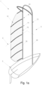
- the boat 1 comprises a hull 2 and a rig 5, comprising in turn a sail 10 hereinafter also referred to as mainsail, and a mast 15, which supports the mainsail on the hull.
- the hull 2 may be of any type, even possibly a multihull, such as for example a catamaran or a trimaran, and identifies with its shape an advancement direction indicated by the arrow X, as well as a plane of symmetry P parallel to such direction.
- the mast 15 has a first and a second section 30, 32 projecting upwards from the hull, preferably they are substantially rectilinear and have the function of supporting the mainsail in two respective operating propulsion positions specular to each other.
- a third section 34 joins the tops of the first and the second section, and is shaped so as to form a continuity of the extension direction of the entire mast. Such section has the function of the overturning section 34 of the mainsail 10 for passing from one of the operating configurations to the other in the change of tack.
- the shape of the mast is a bipodal overturned U.
- the mast has a distance between the first and the second section 30 and 32 such as to embrace all or most of the hull 2.
- Such characteristic is advantageous for increasing the habitability on board.
- cases are also envisaged in which this can be sacrificed, especially during a race, e.g. in the event in which it is decided to adopt as the wind capturing surface the one facing the opposite side to that facing the plane P. Therefore, in that case, the opening of the fork defined by the mast can also be very narrow.
- the mainsail 10 in the operating position has a main vertical extension and has a substantially trapezoidal or rectangular shape where the major base 70 is fixed slidably to the mast along the whole length thereof.
- the mainsail is symmetrical with respect to a substantially horizontal plane O so as to be able to be overturned between the two specular operating positions.
- the mainsail 10 in the operating position is entirely placed aft with respect to the mast 15.
- the mainsail has no boom, whereas as can be seen below it is preferable for there to be a plurality of stiffening sticks 25 distributed in the mainsail.
- the mast 15 comprises a first guide 35 for slidably guiding the mainsail 10 along its own extension line, preferably along the "entire" extension line.
- the first guide 35 is present in each of the three sections 30, 32, 34 and is continuous in the passages between them, so that the mainsail can be overturned by sliding between the two specular operating positions with respect to the plane of symmetry P.
- the line S of Figure 2 indicates the sliding direction.
- the operating configurations are those in which the mainsail is supported by the first or by the second section 30, 32 ( Figure 1 ) whereas the overturning configuration between them is the one in which the device passes at the overturning section 34 ( Figure 2 ).
- the section of Figure 3 shows an example of a sliding guide 35, created in the form of a channel inside the mast 15.
- the mast is preferably a U-shaped folded profile, so that the channel 35 travels along its entire extension line.
- Other examples are not excluded in which the guide is outside the mast, being for example a protuberance.
- the mainsail In general it is preferable for the mainsail to be supported by the mast 15 through a plurality of coupling carriages 40, visible in Figure 3 .
- the carriages are provided with one or more wheels slidably retained by the guide 35, which acts as a rail.
- the rail In the example illustrated the rail is internal and the carriage is inserted therein, however other solutions are not excluded, such as an external rail, e.g. T-shaped, with a carriage placed to embrace it.
- the carriages 40 provide predetermined joining points 41 between the mast and the proximal edge 70 of the mainsail, and preferably also allow the separation thereof. Such joining points 41 are placed in succession with each other in the sliding direction S and between one and the other there is at least one flexion zone 22 of the mainsail 10. For example, each carriage 40 is connected to a stiffening element 25.
- the carriages 40 can also act as coupling points for one or more ropes 99 (visible in Figure 1 ), also known as halyards, for hoisting, lowering and/or overturning the mainsail 10, e.g. such ropes can pass into the mast, e.g. in the first guide 35, so that they are also guided directly or indirectly along the extension of the mast 15, in particular in all three sections 30, 32 and 34.
- ropes 99 visible in Figure 1
- halyards for hoisting, lowering and/or overturning the mainsail 10
- ropes 99 can pass into the mast, e.g. in the first guide 35, so that they are also guided directly or indirectly along the extension of the mast 15, in particular in all three sections 30, 32 and 34.
- the mainsail 10 comprises at least one surface used to capture the wind 20 which, thanks to the overturning described above, always remains the same in each of the two specular operating configurations allowed by the mast.
- the mainsail 10 is generally able to flex, in particular it comprises an alternation of flexion zones 22 and rigid zones 24 in the sliding direction S, where the latter comprise stiffening elements 25.
- the capture device is therefore able to be deformed by flexion to follow the profile of the first sliding guide 35.
- the stiffening elements 25 preferably extend from the edge 70 of the mainsail connected to the mast, at the opposite free edge 71. They preferably have a substantially horizontal arrangement and are substantially parallel to each other.
- the mainsail 10 is a sail made of canvas or the like, where the surface used to capture the wind 20 is the face turned towards the plane of symmetry P.
- the stiffening elements 25 are sticks applied to the sail 20, e.g. externally on the wind capture surface, and the flexion zones 22 are the zones made of canvas or the like between one stick 24 and another.
- the mast 15 comprises at the joining section 34 a second guide 45 that defines a second path or sliding guide point for the mainsail.
- the second guide 45 is distanced in the horizontal direction and aft with respect to the first guide 35, and in general defines a path or sliding point facing the first guide 35.
- the second sliding guide 45 is preferably a support for the mainsail 10, which rests thereon in the passage configuration at the joining section 34, preferably without coupling constraints.
- the second sliding guide 45 is a support arch for supporting the mainsail anchored at the tops of the first and second section of mast 30, 32, from which it projects upwards away from the joining section 34 in the aft direction.
- the second sliding guide 45 can in general be optionally provided with wheels or sliding rollers 46.
- the wear of the mainsail due to rubbing against the second guide 45 can be limited by interposing the sticks between it and the wind capture surface 20.
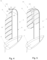
- FIGS 4 and 5 illustrate an alternative embodiment of a boat according to the present invention indicated overall by reference number 101 and that differs from the boat 1 of Figures 1 and 2 substantially due to the shape of the second sliding guide 145.
- the latter comprises a rod 145 projecting aft from the joining section 34.
- the rod extends, preferably substantially horizontally, from one connecting end 147 with the joining section 34, at a free end 148 closer to the stern.
- the rod preferably comprises one or more supports, e.g. one or more further rods 149 for support against the mast 15.
- the second guide 145 comprises more than one rod like the one described, e.g. arranged parallel to each other in succession along the extension direction of the first guide.
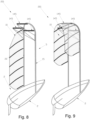
- Figure 6 shows an alternative embodiment of a mainsail 110 that differs from the mainsail 10 of Figures 1 and 2 due to the fact that it is a sail made of canvas or the like kept folded to form an airfoil by means of the plurality of stiffening sticks 125 shaped like a fork.
- Figure 7 generally shows the applicability of any airfoil to a mainsail according to the present invention. It is observed that the airfoil preferably has an asymmetrical camber along the chord, in particular it preferably has a concave side and a convex one, and the wind capture face 220 is the concave one.
- the figure shows the asymmetrical distribution of the thicknesses in a section of the airfoil of the sail highlighting the two central thicknesses with respect to the chord and indicating them with camber 1 and camber 2.
- the mainsail 10 is normally placed in one of the operating configurations in which it is supported on the first or on the second section of mast 30, 32. In such position the surface that captures the wind 20 is turned towards the plane of symmetry P, and its inclination with respect thereto can be modified to obtain a desired interaction with the wind.
- the wind that interacts with such face generates the propulsive thrust of the boat.
- a change of tack such as in the case of veering or tacking (also known as gybing)
- tacking also known as gybing
- the mainsail overturning manoeuvre is performed.
- the latter is placed sliding along the first sliding guide 35.
- the second sliding guide 45, 145 to prevent it falling down again due to the effect of its own weight or gusts of wind.
- the surface that captures the wind unlike Bermuda sails, remains the same in every configuration, to the advantage of the possibility to use optimised asymmetrical cambers.
- mainsails are not excluded where the two main faces can be used indifferently by choice as wind capture surfaces. This is the case for example of sails made of canvas or the like with a constant section thickness.
- the term “comprising” and its derivatives, as used herein, are intended as open-ended terms that specify the presence of declared characteristics, elements, components, groups, integers and/or steps, but do not exclude the presence of other undeclared characteristics, elements, components, groups, integers and/or steps.
- the above also applies to words that have similar meanings such as the terms “comprised”, “have” and their derivatives.
- the terms “part”, “section”, “portion”, “member” or “element” when used in the singular can have the double meaning of a single part or a plurality of parts.
Claims (14)
- Segelboot mit mindestens einem Rumpf (2), der geformt ist, eine Vorschubrichtung im Wasser (X) zu definieren, mindestens einem Rigg (5) mit mindestens einem am Rumpf befestigten Mast (15) und mindestens einem von dem Mast getragenen Großsegel (10), wobei- der Mast mindestens einen ersten und einen zweiten Abschnitt (30, 32) umfasst, die in Bezug auf den Rumpf nach oben ragen und einander gegenüberliegend in der orthogonalen Richtung zur Vorschubrichtung angeordnet sind, um das Großsegel in zwei gegenseitig gespiegelten und alternativen Betriebspositionen zu tragen, wobei die Abschnitte durch mindestens einen Überschlagabschnitt (34) für das Großsegel, der an ihrer Spitze angeordnet ist, verbunden und zueinander beabstandet sind, um den Übergang von einer gespiegelten Position zu der anderen zu ermöglichen, wobei die drei Mastabschnitte zu diesem Zweck eine erste Gleitführung (35) für das Großsegel definieren, die sich im Wesentlichen über die gesamte Ausdehnungslänge des Mastes erstreckt,- das Großsegel (10) ein Segel ist, das verformbar ist, um sich an den Weg der Gleitführung und für das Absenken anzupassen, und in den Betriebspositionen eine vorherrschende Ausdehnung in vertikaler Richtung aufweist,- das Großsegel eine Hauptkante (70) aufweist, die sich in der Nähe des Mastes (15) befindet und über ihre gesamte Länge verschiebbar an dem Gleitweg befestigt ist,- das Großsegel (10) in der Betriebsposition vollständig achtern in Bezug auf den Mast (15) angeordnet ist,dadurch gekennzeichnet, dass- der Mast eine zweite Gleitführung (45, 145) umfasst, die im Wesentlichen an seiner Spitze angeordnet und in Bezug auf den Überschlagabschnitt (34) achtern angeordnet ist, um eine gleitende Stütze für das Großsegel (10) von unten in vertikaler Richtung während des Durchgangs durch den Überschlagabschnitt (34) zu bilden.
- Boot nach Anspruch 1, dadurch gekennzeichnet, dass die zweite Gleitführung frei von Zwangsmitteln für das Großsegel ist und mit diesem ausschließlich durch Auflagekontakt zusammenwirkt.
- Boot nach einem der vorhergehenden Ansprüche, dadurch gekennzeichnet, dass das Großsegel (10) im Wesentlichen trapezförmig oder rechteckig ist, wobei die Seite (70) der Hauptbasis so angeordnet ist, dass sie die proximale Kante bildet, wobei das Trapez oder das Rechteck in der Betriebsposition symmetrisch in Bezug auf eine im Wesentlichen horizontale Symmetrieebene (O) ist.
- Boot nach einem der vorhergehenden Ansprüche, dadurch gekennzeichnet, dass das Großsegel eine flügelförmige Querschnittsdicke vorzugsweise mit asymmetrischer Wölbung entlang der Sehne aufweist.
- Boot nach einem der vorhergehenden Ansprüche, dadurch gekennzeichnet, dass die zweite Gleitführung (45, 145) das Großsegel (10) zumindest in einem beabstandeten Punkt in horizontaler Richtung nach achtern in Bezug auf den Überschlagabschnitt (34) abstützt.
- Boot nach einem der vorhergehenden Ansprüche, dadurch gekennzeichnet, dass das Großsegel eine Vielzahl von Versteifungselementen (25, 125, 325) des Großsegels umfasst, die in Gleitrichtung (S) aufeinander folgend angeordnet sind und sich mit Verformungszonen (22) abwechseln, die die Anpassung an den Gleitweg ermöglichen.
- Boot nach dem vorhergehenden Anspruch, dadurch gekennzeichnet, dass die Versteifungselemente Versteifungsstangen (25, 125) sind, die mit dem Großsegel (10) verbunden sind, vorzugsweise um in direktem Kontakt mit der zweiten Gleitführung (45) zu sein.
- Boot nach Anspruch 6 oder 7, dadurch gekennzeichnet, dass das Verhältnis zwischen dem Abstand der aufeinanderfolgenden Versteifungselemente und der Erstreckung der zweiten Gleitführung (45) so bemessen ist, dass während des Durchlaufs des Überschlagabschnitts (34) von jedem Paar benachbarter Versteifungselemente (25, 125, 325) mindestens eines von der zweiten Führung abgestützt ist.
- Boot nach einem der vorhergehenden Ansprüche, dadurch gekennzeichnet, dass die zweite Gleitführung (45, 145) das Großsegel (10) so abstützt, dass es im Wesentlichen parallel zu der Vorschubrichtung (X) angeordnet bleibt.
- Boot nach einem der vorhergehenden Ansprüche, dadurch gekennzeichnet, dass das Großsegel (10) eine freie distale Kante (71) aufweist, die zu einer vertikalen Symmetrieebene (P) des Mastes hin und von dieser weg beweglich ist, wenn sich das Großsegel in den Betriebspositionen befindet, wobei die zweite Gleitführung (45, 145) die Beweglichkeit des zweiten Kantenabschnitts (71) nach unten begrenzt, wenn das Großsegel den Überschlagabschnitt (34) der ersten Führung passiert.
- Boot nach einem der vorhergehenden Ansprüche, dadurch gekennzeichnet, dass das Großsegel in den Betriebsstellungen keinen Abschnitt oder höchstens einen oberen Teil aufweist, der an der zweiten Gleitführung angeordnet ist.
- Boot nach einem der vorhergehenden Ansprüche, dadurch gekennzeichnet, dass sich der Überschlagabschnitt (34) entlang einer ersten konkaven Linie nach unten erstreckt, die sich im Wesentlichen kontinuierlich an die Spitze der Mastabschnitte anschließt, und dass sich die zweite Gleitführung (45) entlang einer zweiten konkaven Linie nach unten erstreckt, die im Wesentlichen an der Spitze des ersten und des zweiten Mastabschnitts beginnt und zu dem Verbindungsabschnitt beabstandet ist, wobei sie diesem in horizontaler Richtung im Wesentlichen zugewandt ist.
- Boot nach einem der Ansprüche 1 bis 11, dadurch gekennzeichnet, dass die zweite Gleitführung (145) mindestens eine Stange umfasst, die ausgehend von dem Überschlagabschnitt zwischen dem ersten und dem zweiten Mastabschnitt achtern hervorragt.
- Boot nach einem der vorhergehenden Ansprüche, dadurch gekennzeichnet, dass das Großsegel so beschaffen ist, dass die erste Gleitführung eine Schiene umfasst und die proximale Kante (70) des Großsegels (10) gleitend an dem Mast durch eine Vielzahl von Schlitten (40) befestigt ist, die gleitend mit der Schiene gekoppelt sind, wobei die Schlitten jeweils einen Gleitpunkt in Bezug auf die Schiene (35) und einen Kopplungspunkt (41) mit der proximalen Kante umfassen, und wobei jeder Schlitten mindestens einen Anlenkpunkt (42) umfasst, um dem Großsegel zu ermöglichen, die Neigung in Bezug auf den Mast zu ändern.
Priority Applications (1)
| Application Number | Priority Date | Filing Date | Title |
|---|---|---|---|
| HRP20240084TT HRP20240084T1 (hr) | 2018-08-10 | 2019-08-05 | Jedrilica koja se sastoji jarbola u obliku obrnutog u |
Applications Claiming Priority (2)
| Application Number | Priority Date | Filing Date | Title |
|---|---|---|---|
| IT102018000008059A IT201800008059A1 (it) | 2018-08-10 | 2018-08-10 | Imbarcazione a propulsione eolica, relativo armo e relativo albero |
| PCT/IB2019/056633 WO2020031053A1 (en) | 2018-08-10 | 2019-08-05 | Sailing boat comprising an inverted u-shaped mast |
Publications (3)
| Publication Number | Publication Date |
|---|---|
| EP3833596A1 EP3833596A1 (de) | 2021-06-16 |
| EP3833596C0 EP3833596C0 (de) | 2023-10-18 |
| EP3833596B1 true EP3833596B1 (de) | 2023-10-18 |
Family
ID=64049601
Family Applications (1)
| Application Number | Title | Priority Date | Filing Date |
|---|---|---|---|
| EP19769573.7A Active EP3833596B1 (de) | 2018-08-10 | 2019-08-05 | Segelboot mit einem umgedrehten u-förmigen mast |
Country Status (11)
| Country | Link |
|---|---|
| US (1) | US11724777B2 (de) |
| EP (1) | EP3833596B1 (de) |
| JP (1) | JP7423599B2 (de) |
| KR (1) | KR20210041609A (de) |
| CN (1) | CN112839863A (de) |
| AU (1) | AU2019319120A1 (de) |
| HR (1) | HRP20240084T1 (de) |
| IT (1) | IT201800008059A1 (de) |
| MA (1) | MA53278A (de) |
| PL (1) | PL3833596T3 (de) |
| WO (1) | WO2020031053A1 (de) |
Families Citing this family (3)
| Publication number | Priority date | Publication date | Assignee | Title |
|---|---|---|---|---|
| IT202000003359A1 (it) * | 2020-02-19 | 2021-08-19 | Stramba S R L | Sistema di manovra di una vela |
| IT202000003356A1 (it) * | 2020-02-19 | 2021-08-19 | Stramba S R L | Sistema di manovra di una vela |
| IT202000003362A1 (it) * | 2020-02-19 | 2021-08-19 | Stramba S R L | Sistema di manovra di una vela |
Family Cites Families (8)
| Publication number | Priority date | Publication date | Assignee | Title |
|---|---|---|---|---|
| US449472A (en) * | 1891-03-31 | Hiram follett | ||
| US3112725A (en) * | 1960-11-15 | 1963-12-03 | Malrose Le Roy | Sailboat |
| FR2068031A5 (de) * | 1969-11-25 | 1971-08-20 | Mathon Paul | |
| US4388888A (en) * | 1981-04-24 | 1983-06-21 | Gushurst Jr Fred W | Adjustable airfoil |
| FR2825341A1 (fr) * | 2001-06-01 | 2002-12-06 | Strathcona Nt Pty Ltd | Vehicule a propulsion eolienne tel qu'un bateau a voile |
| DE102004012760A1 (de) * | 2004-03-15 | 2005-10-06 | Glasfieber Guergen & Meyenburg Kg | Mehrrumpfsegelfahrzeug |
| IT1393133B1 (it) * | 2009-03-09 | 2012-04-11 | Marcello Segato | Sistema velico perfezionato |
| ITUA20162557A1 (it) * | 2016-04-13 | 2017-10-13 | Stramba S R L | Armo per un mezzo nautico e mezzo nautico comprendente detto armo |
-
2018
- 2018-08-10 IT IT102018000008059A patent/IT201800008059A1/it unknown
-
2019
- 2019-08-05 JP JP2021505258A patent/JP7423599B2/ja active Active
- 2019-08-05 HR HRP20240084TT patent/HRP20240084T1/hr unknown
- 2019-08-05 PL PL19769573.7T patent/PL3833596T3/pl unknown
- 2019-08-05 AU AU2019319120A patent/AU2019319120A1/en active Pending
- 2019-08-05 US US17/263,250 patent/US11724777B2/en active Active
- 2019-08-05 WO PCT/IB2019/056633 patent/WO2020031053A1/en unknown
- 2019-08-05 KR KR1020217007339A patent/KR20210041609A/ko active IP Right Grant
- 2019-08-05 EP EP19769573.7A patent/EP3833596B1/de active Active
- 2019-08-05 MA MA053278A patent/MA53278A/fr unknown
- 2019-08-05 CN CN201980066247.4A patent/CN112839863A/zh active Pending
Also Published As
| Publication number | Publication date |
|---|---|
| KR20210041609A (ko) | 2021-04-15 |
| HRP20240084T1 (hr) | 2024-03-29 |
| WO2020031053A1 (en) | 2020-02-13 |
| EP3833596C0 (de) | 2023-10-18 |
| MA53278A (fr) | 2021-11-17 |
| PL3833596T3 (pl) | 2024-03-18 |
| CN112839863A (zh) | 2021-05-25 |
| EP3833596A1 (de) | 2021-06-16 |
| US20210163101A1 (en) | 2021-06-03 |
| AU2019319120A1 (en) | 2021-03-25 |
| IT201800008059A1 (it) | 2020-02-10 |
| US11724777B2 (en) | 2023-08-15 |
| JP7423599B2 (ja) | 2024-01-29 |
| JP2022500291A (ja) | 2022-01-04 |
Similar Documents
| Publication | Publication Date | Title |
|---|---|---|
| EP3833596B1 (de) | Segelboot mit einem umgedrehten u-förmigen mast | |
| US4263861A (en) | Sailing craft | |
| US8776708B2 (en) | Mechanised device for rigging a sail | |
| EP0232413B1 (de) | Regelsystem für bootsegel | |
| EP3052379B1 (de) | Verfahren zur handhabung und steuerung von profilsegeln | |
| RU2739297C2 (ru) | Оснастка для мореплавательных средств и мореплавательные средства, содержащие указанную оснастку | |
| US7574972B1 (en) | Three-dimensional sail apparatus | |
| US4723498A (en) | Sailboat rigging | |
| AU2014331535A1 (en) | Method for rigging and controlling a wing sail | |
| US5083520A (en) | Mast, in particular for sailing boat | |
| JP5538387B2 (ja) | 遠洋航行貨物船やヨット等専用の帆走システム | |
| EP2404820A1 (de) | Windbetriebenes Fahrzeug mit Flügelsegel | |
| DK2704944T3 (en) | Sailing, which has a float structure with a mast | |
| US8234991B2 (en) | Sail propulsion system | |
| US8893635B2 (en) | Canted sail rig | |
| AU585930B2 (en) | Rigging for a wind propelled craft | |
| CN110337403A (zh) | 稳定旋转帆索具 | |
| EP1557350A1 (de) | Hochleistungssegelboot mit Flügelelementen und Auftrieb erzeugenden Segeln | |
| US20110048307A1 (en) | Tunnel Rigging | |
| FI96106C (fi) | Harusisopurje ja sen säätöjärjestelmä | |
| GB2342633A (en) | Articulated sail rig | |
| WO2012094731A1 (en) | Microairfoil and method for rigging and control | |
| NZ719265B2 (en) | Method for rigging and controlling a wing sail | |
| GB2349623A (en) | Balanced articulated sail rig |
Legal Events
| Date | Code | Title | Description |
|---|---|---|---|
| REG | Reference to a national code |
Ref country code: HR Ref legal event code: TUEP Ref document number: P20240084T Country of ref document: HR |
|
| STAA | Information on the status of an ep patent application or granted ep patent |
Free format text: STATUS: UNKNOWN |
|
| STAA | Information on the status of an ep patent application or granted ep patent |
Free format text: STATUS: THE INTERNATIONAL PUBLICATION HAS BEEN MADE |
|
| PUAI | Public reference made under article 153(3) epc to a published international application that has entered the european phase |
Free format text: ORIGINAL CODE: 0009012 |
|
| STAA | Information on the status of an ep patent application or granted ep patent |
Free format text: STATUS: REQUEST FOR EXAMINATION WAS MADE |
|
| 17P | Request for examination filed |
Effective date: 20210303 |
|
| AK | Designated contracting states |
Kind code of ref document: A1 Designated state(s): AL AT BE BG CH CY CZ DE DK EE ES FI FR GB GR HR HU IE IS IT LI LT LU LV MC MK MT NL NO PL PT RO RS SE SI SK SM TR |
|
| DAX | Request for extension of the european patent (deleted) | ||
| RAV | Requested validation state of the european patent: fee paid |
Extension state: MA Effective date: 20210303 |
|
| REG | Reference to a national code |
Ref country code: DE Ref legal event code: R079 Ref document number: 602019039653 Country of ref document: DE Free format text: PREVIOUS MAIN CLASS: B63B0015000000 Ipc: B63H0009068000 Ref legal event code: R079 Ipc: B63H0009068000 |
|
| GRAP | Despatch of communication of intention to grant a patent |
Free format text: ORIGINAL CODE: EPIDOSNIGR1 |
|
| STAA | Information on the status of an ep patent application or granted ep patent |
Free format text: STATUS: GRANT OF PATENT IS INTENDED |
|
| RIC1 | Information provided on ipc code assigned before grant |
Ipc: B63B 15/00 20060101ALI20230414BHEP Ipc: B63H 9/08 20060101ALI20230414BHEP Ipc: B63H 9/068 20200101AFI20230414BHEP |
|
| INTG | Intention to grant announced |
Effective date: 20230510 |
|
| P01 | Opt-out of the competence of the unified patent court (upc) registered |
Effective date: 20230527 |
|
| GRAS | Grant fee paid |
Free format text: ORIGINAL CODE: EPIDOSNIGR3 |
|
| GRAA | (expected) grant |
Free format text: ORIGINAL CODE: 0009210 |
|
| STAA | Information on the status of an ep patent application or granted ep patent |
Free format text: STATUS: THE PATENT HAS BEEN GRANTED |
|
| AK | Designated contracting states |
Kind code of ref document: B1 Designated state(s): AL AT BE BG CH CY CZ DE DK EE ES FI FR GB GR HR HU IE IS IT LI LT LU LV MC MK MT NL NO PL PT RO RS SE SI SK SM TR |
|
| RAP3 | Party data changed (applicant data changed or rights of an application transferred) |
Owner name: STRAMBA S.R.L. |
|
| REG | Reference to a national code |
Ref country code: GB Ref legal event code: FG4D |
|
| REG | Reference to a national code |
Ref country code: CH Ref legal event code: EP |
|
| REG | Reference to a national code |
Ref country code: IE Ref legal event code: FG4D |
|
| REG | Reference to a national code |
Ref country code: DE Ref legal event code: R096 Ref document number: 602019039653 Country of ref document: DE |
|
| U01 | Request for unitary effect filed |
Effective date: 20231120 |
|
| U07 | Unitary effect registered |
Designated state(s): AT BE BG DE DK EE FI FR IT LT LU LV MT NL PT SE SI Effective date: 20231127 |
|
| P04 | Withdrawal of opt-out of the competence of the unified patent court (upc) registered |
Effective date: 20231122 |
|
| REG | Reference to a national code |
Ref country code: GR Ref legal event code: EP Ref document number: 20240400168 Country of ref document: GR Effective date: 20240209 |
|
| REG | Reference to a national code |
Ref country code: HR Ref legal event code: T1PR Ref document number: P20240084 Country of ref document: HR |
|
| PG25 | Lapsed in a contracting state [announced via postgrant information from national office to epo] |
Ref country code: IS Free format text: LAPSE BECAUSE OF FAILURE TO SUBMIT A TRANSLATION OF THE DESCRIPTION OR TO PAY THE FEE WITHIN THE PRESCRIBED TIME-LIMIT Effective date: 20240218 |