EP3833477B1 - Behälter zur behandlung einer flüssigkeit mit einem ionenaustauschsystem und entsprechendes ionenchromatographieverfahren - Google Patents
Behälter zur behandlung einer flüssigkeit mit einem ionenaustauschsystem und entsprechendes ionenchromatographieverfahren Download PDFInfo
- Publication number
- EP3833477B1 EP3833477B1 EP19745746.8A EP19745746A EP3833477B1 EP 3833477 B1 EP3833477 B1 EP 3833477B1 EP 19745746 A EP19745746 A EP 19745746A EP 3833477 B1 EP3833477 B1 EP 3833477B1
- Authority
- EP
- European Patent Office
- Prior art keywords
- container
- fluid
- particles
- chamber
- diffusers
- Prior art date
- Legal status (The legal status is an assumption and is not a legal conclusion. Google has not performed a legal analysis and makes no representation as to the accuracy of the status listed.)
- Active
Links
Images


Classifications
-
- G—PHYSICS
- G01—MEASURING; TESTING
- G01N—INVESTIGATING OR ANALYSING MATERIALS BY DETERMINING THEIR CHEMICAL OR PHYSICAL PROPERTIES
- G01N30/00—Investigating or analysing materials by separation into components using adsorption, absorption or similar phenomena or using ion-exchange, e.g. chromatography or field flow fractionation
- G01N30/02—Column chromatography
- G01N30/60—Construction of the column
- G01N30/6004—Construction of the column end pieces
- G01N30/6017—Fluid distributors
-
- B—PERFORMING OPERATIONS; TRANSPORTING
- B01—PHYSICAL OR CHEMICAL PROCESSES OR APPARATUS IN GENERAL
- B01D—SEPARATION
- B01D15/00—Separating processes involving the treatment of liquids with solid sorbents; Apparatus therefor
- B01D15/08—Selective adsorption, e.g. chromatography
- B01D15/10—Selective adsorption, e.g. chromatography characterised by constructional or operational features
- B01D15/22—Selective adsorption, e.g. chromatography characterised by constructional or operational features relating to the construction of the column
-
- B—PERFORMING OPERATIONS; TRANSPORTING
- B01—PHYSICAL OR CHEMICAL PROCESSES OR APPARATUS IN GENERAL
- B01D—SEPARATION
- B01D15/00—Separating processes involving the treatment of liquids with solid sorbents; Apparatus therefor
- B01D15/08—Selective adsorption, e.g. chromatography
- B01D15/26—Selective adsorption, e.g. chromatography characterised by the separation mechanism
- B01D15/36—Selective adsorption, e.g. chromatography characterised by the separation mechanism involving ionic interaction, e.g. ion-exchange, ion-pair, ion-suppression or ion-exclusion
- B01D15/361—Ion-exchange
- B01D15/363—Anion-exchange
-
- B—PERFORMING OPERATIONS; TRANSPORTING
- B01—PHYSICAL OR CHEMICAL PROCESSES OR APPARATUS IN GENERAL
- B01J—CHEMICAL OR PHYSICAL PROCESSES, e.g. CATALYSIS OR COLLOID CHEMISTRY; THEIR RELEVANT APPARATUS
- B01J41/00—Anion exchange; Use of material as anion exchangers; Treatment of material for improving the anion exchange properties
- B01J41/04—Processes using organic exchangers
- B01J41/07—Processes using organic exchangers in the weakly basic form
-
- B—PERFORMING OPERATIONS; TRANSPORTING
- B01—PHYSICAL OR CHEMICAL PROCESSES OR APPARATUS IN GENERAL
- B01J—CHEMICAL OR PHYSICAL PROCESSES, e.g. CATALYSIS OR COLLOID CHEMISTRY; THEIR RELEVANT APPARATUS
- B01J41/00—Anion exchange; Use of material as anion exchangers; Treatment of material for improving the anion exchange properties
- B01J41/08—Use of material as anion exchangers; Treatment of material for improving the anion exchange properties
- B01J41/12—Macromolecular compounds
- B01J41/13—Macromolecular compounds obtained otherwise than by reactions only involving unsaturated carbon-to-carbon bonds
-
- B—PERFORMING OPERATIONS; TRANSPORTING
- B01—PHYSICAL OR CHEMICAL PROCESSES OR APPARATUS IN GENERAL
- B01J—CHEMICAL OR PHYSICAL PROCESSES, e.g. CATALYSIS OR COLLOID CHEMISTRY; THEIR RELEVANT APPARATUS
- B01J47/00—Ion-exchange processes in general; Apparatus therefor
- B01J47/02—Column or bed processes
- B01J47/022—Column or bed processes characterised by the construction of the column or container
-
- B—PERFORMING OPERATIONS; TRANSPORTING
- B01—PHYSICAL OR CHEMICAL PROCESSES OR APPARATUS IN GENERAL
- B01J—CHEMICAL OR PHYSICAL PROCESSES, e.g. CATALYSIS OR COLLOID CHEMISTRY; THEIR RELEVANT APPARATUS
- B01J47/00—Ion-exchange processes in general; Apparatus therefor
- B01J47/02—Column or bed processes
- B01J47/04—Mixed-bed processes
-
- B—PERFORMING OPERATIONS; TRANSPORTING
- B01—PHYSICAL OR CHEMICAL PROCESSES OR APPARATUS IN GENERAL
- B01J—CHEMICAL OR PHYSICAL PROCESSES, e.g. CATALYSIS OR COLLOID CHEMISTRY; THEIR RELEVANT APPARATUS
- B01J47/00—Ion-exchange processes in general; Apparatus therefor
- B01J47/10—Ion-exchange processes in general; Apparatus therefor with moving ion-exchange material; with ion-exchange material in suspension or in fluidised-bed form
-
- G—PHYSICS
- G01—MEASURING; TESTING
- G01N—INVESTIGATING OR ANALYSING MATERIALS BY DETERMINING THEIR CHEMICAL OR PHYSICAL PROPERTIES
- G01N30/00—Investigating or analysing materials by separation into components using adsorption, absorption or similar phenomena or using ion-exchange, e.g. chromatography or field flow fractionation
- G01N30/02—Column chromatography
- G01N30/60—Construction of the column
- G01N30/6052—Construction of the column body
- G01N30/6069—Construction of the column body with compartments or bed substructure
-
- G—PHYSICS
- G01—MEASURING; TESTING
- G01N—INVESTIGATING OR ANALYSING MATERIALS BY DETERMINING THEIR CHEMICAL OR PHYSICAL PROPERTIES
- G01N30/00—Investigating or analysing materials by separation into components using adsorption, absorption or similar phenomena or using ion-exchange, e.g. chromatography or field flow fractionation
- G01N30/96—Investigating or analysing materials by separation into components using adsorption, absorption or similar phenomena or using ion-exchange, e.g. chromatography or field flow fractionation using ion-exchange
Definitions
- the application relates generally to ion chromatography and, more particularly, to an ion-exchange system and method thereof.
- Ion exchanger systems such as those employed in ion chromatography, can be used to remove or separate molecules from a fluid.
- the fluid may pass upwardly through a bed of ion-exchange resin contained in a container of the ion exchanger system to remove the molecules from the fluid.
- the ion exchanger system typically has an inlet at the bottom to receive the fluid into the container and an outlet at the top to remove the fluid from the container.
- the fluid can be pressurized and injected into the container.
- the amount of molecules removed from the fluid may depend on the time that the fluid is in contact with the bed of ion-exchange resin. However, a portion of the fluid may pass through the resin at a rate different from rates of other portions of the fluid passing through the resin.
- US 3 802 568 A discloses a device or apparatus for continuously treating fluids in an ion exchange bed.
- the device or apparatus comprises a lid, a hollow body, a bottom, an upper intermediate plate, and a lower intermediate plate.
- a container for treating a fluid with an ion-exchange system comprising a housing extending in an upright position along a longitudinal axis between a bottom port and an opposed top port, the housing having an internal chamber defined therein; a bottom plate disposed in the internal chamber perpendicular to the longitudinal axis at a predetermined height above the bottom port and having a plurality of openings defined therethrough, the bottom plate dividing the internal chamber between a main chamber and a bottom chamber, the bottom chamber defined between the bottom plate and the bottom port; and a plurality of diffusers in fluid flow communication with the bottom chamber extending from the bottom plate into the main chamber, each one of the plurality of diffusers being received in a respective one of the plurality of openings of the bottom plate and having a diffuser tube section projecting upwardly from the bottom plate and being in fluid flow communication with the bottom chamber, the diffuser tube section having radial openings circumferentially distributed along a length thereof to
- an ion chromatography method for treating a fluid with ion-exchange treatment particles disposed in a container comprising uniformly distributing the fluid in a bed of silex particles of the treatment particles through a plurality of bottom diffusers; raising the fluid from the bed of silex particles into, and through, a bed of ion-exchange particles of the treatment particles; and evacuating the fluid from the container.
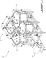
- Fig. 1 illustrates an ion-exchange system 10 that may be used in ion chromatography.
- the ion-exchange system 10 may be used for treating a fluid to remove ions, particles, and/or molecules from the fluid.
- the ion-exchange system may be used in the food and beverage industry as part of a purification and separation system.
- the ion-exchange system 10 may be used in juice debittering, juice clarification, and the like. It is understood that other suitable applications outside the beverage industry for removing ions, particles and/or molecules from the fluid using the ion-exchange system 10 are also contemplated.
- the ion-exchange system 10 includes four containers 12.
- the container 12 is intended to refer to a vessel, receptacle, tank, and the like.
- the container 12 may receive and treat the fluid with treatment particles that may be disposed therein.
- the treatment particles may contain a bed of ion-exchange particles or resin to treat the fluid.
- the ion-exchange particles are intended to refer to resins, beads, or the like, that can separate ions and/or molecules from the fluid.
- the ion-exchange resin may be selected to provide the desired separation and removal of the ions and/or molecules from the fluid.
- the ion-exchange particles or resin to treat the fluid is preferably a weak anion exchange resin such as a resin of the acrylic or styrene type.
- weak anion exchange resin is comprising ternary amines that are neutral at a pH greater than 10 and ionized at a pH lower than 10 and may therefore be useful for capturing chemical species (such as weak acids, in particular organic acids).
- the resin is an acrylic-type anion exchange resin having a capacity between 1.6-3.2.
- the container 12 may include any suitable material for containing the fluid and the treatment particles.
- the ion-exchange system may include a pump 14 to pressurize the fluid and a piping network 16 to carry the fluid into and out of the containers 12.
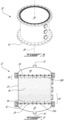
- Figs. 2A-2C illustrates the container 12.
- the container 12 has a housing 20 to receive the treatment particles, a bottom cover 22, an opposed top cover 24, and diffusers 26 positioned inside the container 12 to distribute the fluid in the housing 20.
- the fluid may be uniformly distributed across the housing 20 through the diffusers 26.
- relative terms such as, “top”, “bottom”, “side”, “horizontal”, “vertical”, “upright”, “above”, and the like are used herein to describe one element's relationship to another element as illustrated in the figures. It is understood that these relative terms are intended to encompass different orientations of the elements in addition to the orientation depicted in the figures.
- the housing 20 may extend in an upright position along a longitudinal axis 28 ( Fig. 2B ) between a bottom port 30 defined in the bottom cover 22 and an opposed top port 32 defined in the top cover 24.
- the bottom port 30 and the top port 32 may be openings.
- the fluid may be introduced in the container 12 from the bottom port 30 and/or the top port 32 and evacuated from the bottom port 30 and/or the top port 32, and vice versa.
- a fluid source (not shown) may provide the fluid to the container 12.
- the fluid may be pressurized and injected into the container 12.
- the pump 14 may pressurize the fluid.
- a vacuum pump may be connected to the top port 32 to evacuate the fluid from the container 12.
- the housing 20 may have a sidewall 34 extending around the longitudinal axis 28 from the bottom cover 22 to the top cover 24.
- the housing 20 may have a cylindrical shape. In some embodiments, the housing 20 may have an oval shape.
- the container 12 has an internal chamber defined therein.
- the internal chamber may be divided into sub-chambers.
- the container 12 may have a main chamber 36, a bottom chamber 38, and a top chamber 40.
- the main chamber 36 is disposed between the bottom chamber 38 and the top chamber 40.
- the main chamber 36 is defined in the housing 20 such that the sidewall 34 at least partially delimits the main chamber 36.
- the main chamber 36 is adapted to contain therein the treatment particles.
- the bottom chamber 38 is defined between the main chamber 36 and the bottom cover 22, and the top chamber 40 is defined between the main chamber 36 and the top cover 24.
- the bottom chamber 38 is free from the treatment particles.
- the top chamber 40 may be free from the treatment particles.
- the container 12 includes a bottom plate 42 disposed therein at a predetermined height above the bottom port 30 such that the bottom chamber 38 may be defined between the bottom plate 42 and the bottom port 30.
- the bottom plate 42 may be disposed perpendicular to the longitudinal axis 28.
- the bottom plate 42 delimits a bottom portion of the main chamber 36.
- the bottom plate 42 may extend across the sidewall 34 of the housing 20. In other words, a periphery of the bottom plate 42 may be in contact with the sidewall 34.
- the bottom plate 42 may form a common divider between the main chamber 36 and the bottom chamber 38.
- the container 12 may include a top plate 44 disposed therein at a predetermined depth below the top port 32 such that the top chamber 40 may be defined between the top plate 44 and the top port 32.
- the top plate 44 may be disposed perpendicular to the longitudinal axis 28.
- the top plate 44 delimits a top portion of the main chamber 36.
- the top plate 44 may extend across the sidewall 34 of the housing 20. In other words, a periphery of the top plate 44 may be in contact with the sidewall 34.
- the top plate 44 may form a common divider between the main chamber 36 and the top chamber 40.
- the diffusers 26 may include bottom diffusers 26A that extend from the bottom plate 42 into the main chamber 36.
- each diffuser 26 has a diffuser tube section 46 that projects upwardly from the bottom plate 42 into the main chamber 36.
- a predetermined height of the diffuser tube section 46 may be determined relative to the size and shape of the container 12. The predetermined height of the diffuser tube section 46 may depend on the selection of the treatment particles.
- the treatment particles may include the bed of ion-exchange particles disposed above a bed of silex particles.
- the silex particles are intended to refer to any suitable forms of quartz, flint, stones, or any of the other forms of silica and/or silicate, and the like.
- the height of the diffuser tube section 46 may extend only within the bed of silex particles. In some embodiments, the diffuser tube section 46 may not extend in the bed of ion-exchange particles.
- the bottom diffusers 26A may be uniformly distributed over the bottom plate 42.
- the bottom diffusers 26A are in fluid flow communication with the bottom chamber 38.
- the fluid may be injected into the bottom chamber 38 through the bottom port 30.
- the fluid may flow into the diffusers 26 to be radially discharged in the main chamber 36.
- the container 12 may include top diffusers 26B that extend from the top plate 44 into the main chamber 36.
- each diffuser has a diffuser tube section 46 that projects downwardly from the top plate 44 into the main chamber 36.
- a predetermined depth of the diffuser tube section 46 may be determined relative to the size and shape of the container 12. The predetermined depth of the diffuser tube section 46 may depend on the selection of the treatment particles.
- the treatment particles may include the bed of silex particles disposed above the bed of ion-exchange particles.
- the depth of the diffuser tube section 46 may extend only in the bed of silex particles.
- the diffuser tube section 46 of the top diffusers 26B may not extend in the bed of ion-exchange particles.
- the top diffusers 26B may be uniformly distributed over the top plate 44.
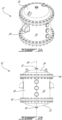
- top cover 24 is shown.
- the top port 32 is positioned in a center of the top cover 24. It is understood that other configurations of the top port 32 may be employed.
- the bottom cover 22 may be similar to the top cover 24.
- the bottom plate 42 is shown.
- the bottom plate 42 is perforated and includes openings 48 defined therethrough.
- Each opening 48 may receive a corresponding diffuser 26.
- the corresponding diffuser 26 may extend through the bottom plate 42 through a respective opening 48.
- each one of the openings 48 of the bottom plate 42 is in fluid flow communication with a corresponding diffuser tube section 46. That is, two or more openings 48 may be in fluid flow communication with the same diffuser tube section 46.
- the diffuser 26AA expands over four openings 48.
- the diffuser 26A expands over one opening 48.
- the bottom plate 42 may have a circular shape. In other embodiments, the bottom plate 42 may have a different shape, such as oval, and the like.
- a density of the diffusers 26 may be defined by a number of the diffusers 26 per unit area of the bottom plate 42. In some embodiments, the density of the diffusers 26 is between a minimum value and a maximum value of diffusers 26 per meter square (number of diffusers/m 2 ). In some embodiments, the density is between 50 and 70 diffusers/m 2 . In some embodiments, the density is between 60 and 65 diffusers/m 2 . In some embodiments, the density is, or about, 62.5 diffusers/m 2 . The density of the diffusers may be 0.016 m 2 /diffuser tube.
- the area of the bottom plate 42 is 0.64 m 2 .
- 40 diffusers 26 may be used and uniformly distributed over the bottom plate 42.
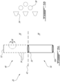
- the diffuser tube section 46 has a root opening 50 at one end and a closed opposite end 52.
- the diffuser tube section 46 may be in fluid flow communication with the bottom chamber 38 through the root opening 50.
- the diffuser tube section 46 may have radial openings 54 circumferentially distributed along a length thereof between the bottom plate 42 and the closed end 52. A flow path of the fluid may be defined from the root opening 50 to the radial openings 54.
- the diffuser 26 may include the diffuser tube section 46 and a root tube section 56.
- the root tube section 56 is intended to refer to any suitable tube to reach the fluid within the bottom chamber 38.
- the root tube section 56 may project from the bottom plate 42 into the bottom chamber 38.
- the root tube section 56 may be in fluid flow communication with the bottom chamber 38 through another root opening 50A.
- the diffuser 26 may be sized to provide a pressure drop therethrough.
- the pressure drop may be between 1 and 3 bars for a flow of the fluid at a volumetric flow rate between 60 and 70 meter cube per hour (m 3 /h).
- the diffusers 26 may be sized and shaped to uniformly distribute the fluid in the bed of silex particles.
- the diffuser tube section 46 may have a diameter that is between 14 mm and 17 mm.
- the height of the diffuser tube section 46 may be about 50 mm. It is understood that other sizes of the diameter and the height may be used.
- a flowrate of the fluid per diffuser 26 may vary between 25 litres per hour (L/h) and 1 500 L/h.
- the pump 14 may vary the flowrate of the fluid flowing to the diffusers 26.
- the diffuser 26 may be made from a stainless steel, titanium alloy, or a combination of stainless steel and titanium alloy.
- the diffuser 26 may be made from a titanium loaded stainless steel.
- the material of the diffuser 26 may be known as "Alloy 316 Ti”.
- the radial openings 54 may have V-shaped openings.
- the V-shaped openings 54 may block the silex particles 58 from entering into the diffusers 26.
- the size of the silex particle 58 may be greater than the size of the radial opening 54.
- the housing 20 may have a height along the longitudinal axis 28 and a diameter extending in a plane perpendicular to the longitudinal axis 28.
- the shape of the housing 20 may be referred to as "super square".
- the term super square is intended to refer to a shape of the housing 20 where the values of the height and the diameter are equal, or are near each other.
- a ratio of the height over the diameter may be between 0.75 and 1.25.
- the ratio of the height over the diameter is between 0.8 and 1.2.
- the ratio of the height over the diameter is between 0.9 and 1.1.
- the ratio of the height over the diameter is, or about, 1.
- the treatment particles may be provided inside the main chamber 36 to a filling height that extends from the bottom plate 42 toward the top plate.
- the filling height may be between 50% and 100% of the total height of the housing 20.
- the treatment particles may expand in volume during the treatment of the fluid.
- the container 12 may be sold separately from the treatment particles.
- the container 12 may be sold with the bed of silex particles 58 and the bed of ion-exchange particles.
- the ion-exchange system 10 may include the container 12 with an identical bottom half and top half. That is, for example, the top plate 44 and top diffusers 26B mirror the bottom plate 42 and bottom diffusers 26A.
- a regenerating or washing fluid may be used to regenerate or wash the ion-exchange particles. For example, after treating the fluid, the ion-exchange particles may be washed to remove the molecules that were separated from the fluid, the molecules retained by the ion-exchange particles, or both.
- a method may be provided for treating the fluid.
- the method may include uniformly distributing the fluid in the bed of silex particles 58 in the container 12, raising the fluid from the bed of silex particles into, and through, the bed of ion-exchange particles, and evacuating or retrieving the fluid from the container 12.
- the method may include a reverse washing flow from the top port 32 to the bottom port 30 to wash and regenerate the ion-exchange particles.
- the fluid may flow through the container 12 from the bottom port 30, to the bottom chamber 38, to the main chamber 36, to the top chamber 40, and flow out of the container 12 through the top port 32.
- the fluid may enter the housing 20 through the bottom port 30.
- the fluid may flow into the bottom diffusers 26A.
- the bottom diffusers 26A may uniformly discharge the fluid in the bed of silex particles 58.
- the fluid may rise from the bed of silex particles 58 into the bed of ion-exchange particles 60.
- the fluid may flow into the top diffusers 26B.
- the fluid may exit the container through the top port 32.
- the fluid may flow through the container 12 from the top port 32, to the top chamber 40, to the main chamber 36, to the bottom chamber 38, and flow out of the container 12 through the bottom port 30.
- the fluid may enter the housing 20 through the top port 32.
- the fluid may flow into the top diffusers 26B.
- the top diffusers 26B may uniformly discharge the fluid in the bed of silex particles 58.
- the fluid may flow from the bed of silex particles 58 into the bed of ion-exchange particles 60.
- the fluid may flow into the bottom diffusers 26A.
- the fluid may exit the container through the bottom port 30.
- the bottom diffusers may be identical to the top diffusers.
- the bottom plate 42 may be identical to the top plate.
Landscapes
- Chemical & Material Sciences (AREA)
- Chemical Kinetics & Catalysis (AREA)
- Organic Chemistry (AREA)
- Analytical Chemistry (AREA)
- General Health & Medical Sciences (AREA)
- Biochemistry (AREA)
- Physics & Mathematics (AREA)
- General Physics & Mathematics (AREA)
- Immunology (AREA)
- Pathology (AREA)
- Life Sciences & Earth Sciences (AREA)
- Health & Medical Sciences (AREA)
- Devices And Processes Conducted In The Presence Of Fluids And Solid Particles (AREA)
- Treatment Of Water By Ion Exchange (AREA)
Claims (16)
- Behälter (12) zur Behandlung eines Fluids mit einem lonenaustauschsystem (10), wobei der Behälter (12) Folgendes umfasst:ein Gehäuse (20), das sich in einer aufrechten Position entlang einer Längsachse (28) zwischen einer unteren Öffnung (30) und einer gegenüberliegenden oberen Öffnung (32) erstreckt, wobei das Gehäuse (20) eine darin definierte innere Kammer aufweist;eine untere Platte (42), die in der inneren Kammer senkrecht zur Längsachse (28) in einer vorbestimmten Höhe über der unteren Öffnung (30) angeordnet ist und eine Vielzahl von durch sie hindurch definierten Öffnungen (48) aufweist, wobei eine untere Kammer (38) zwischen der unteren Platte (42) und der unteren Öffnung (30) definiert ist; undeine Vielzahl von Diffusoren (26A) in Fluidströmungsverbindung mit der unteren Kammer (38), die sich von der unteren Platte (42) in eine Hauptkammer (36) erstrecken, wobei jeder der Vielzahl von Diffusoren (26A) in einer entsprechenden der Vielzahl von Öffnungen (48) der unteren Platte (42) aufgenommen ist und einen Diffusorrohrabschnitt (46) aufweist, der von der unteren Platte (42) nach oben ragt und in Fluidströmungsverbindung mit der unteren Kammer (38) steht, wobei der Diffusorrohrabschnitt (46) radiale Öffnungen (54) aufweist, die in Umfangsrichtung entlang seiner Länge verteilt sind, um das Fluid in der Hauptkammer (36) radial abzugeben,dadurch gekennzeichnet, dass die untere Platte (42) die innere Kammer zwischen der Hauptkammer (36) und der unteren Kammer (38) unterteilt.
- Behälter (12) nach Anspruch 1, wobei die Hauptkammer (36) eine Höhe entlang der Längsachse (28) und einen Durchmesser aufweist, der sich in einer Ebene senkrecht zur Längsachse (28) erstreckt, und ein Verhältnis der Höhe zum Durchmesser zwischen 0,75 und 1,25 beträgt.
- Behälter (12) nach Anspruch 1 oder 2, wobei eine Dichte der Vielzahl von Diffusoren (26A) zwischen 50 und 70 beträgt, wobei die Dichte der Vielzahl von Diffusoren (26A) als eine Anzahl der Vielzahl von Diffusoren (26A) pro Quadratmeter der unteren Platte (42) definiert ist.
- Behälter (12) nach einem der Ansprüche 1 bis 3, wobei jeder der Vielzahl von Diffusoren (26A) so ausgelegt ist, dass er einen Druckabfall durch ihn hindurch bereitstellt, wobei der Druckabfall zwischen 1 und 3 bar für eine Strömung des Fluids bei einer volumetrischen Durchflussrate zwischen 60 und 70 Kubikmetern pro Stunde beträgt.
- Behälter (12) nach einem der Ansprüche 1 bis 4, wobei eine Länge des Diffusorrohrabschnitts (46) so ausgelegt ist, dass er sich nur in einem Bett aus Silexpartikeln erstreckt.
- Behälter (12) nach einem der Ansprüche 1 bis 5, wobei der Diffusorrohrabschnitt (46) eine Wurzelöffnung (50A) an einem ersten Ende davon in Fluidströmungsverbindung mit der unteren Kammer (38) und ein geschlossenes zweites Ende gegenüber dem ersten Ende aufweist, wobei die radialen Diffusoröffnungen (54) so verteilt sind, dass sie das Fluid gleichmäßig in dem Bett aus Silexpartikeln (48) verteilen.
- Behälter (12) nach einem der Ansprüche 1 bis 6, wobei der Behälter (12) eine zylindrische Form aufweist.
- Behälter (12) nach einem der Ansprüche 1 bis 7, weiter einschließend eine obere Platte, wobei sich die Hauptkammer (36) entlang der Längsachse (28) zwischen der unteren Platte (42) und der oberen Platte (44) erstreckt, wobei die obere Platte (44) eine Vielzahl von Öffnungen (48) aufweist, die durch sie hindurch definiert sind.
- Behälter (12) nach Anspruch 8, umfassend eine Vielzahl von oberen Diffusoren (26B), die sich durch die obere Platte (44) erstrecken, wobei jeder der Vielzahl von oberen Diffusoren (26B) den Diffusorrohrabschnitt (46) aufweist, der in die Hauptkammer (36) parallel zur Längsachse (28) durch eine jeweilige der Vielzahl von Öffnungen der oberen Platte (44) ragt.
- Behälter (12) nach Anspruch 9, wobei eine Dichte der Vielzahl von oberen Diffusoren (26B) zwischen 50 und 70 beträgt, wobei die Dichte der Vielzahl von oberen Diffusoren (26B) als eine Anzahl der Vielzahl von oberen Diffusoren (26B) pro Quadratmeter der oberen Platte definiert ist.
- Behälter (12) nach Anspruch 9 oder 10, wobei jeder der Vielzahl von oberen Diffusoren (26B) so ausgelegt ist, dass er einen Druckabfall durch ihn hindurch bereitstellt, wobei der Druckabfall zwischen 1 und 3 bar für eine Strömung des Fluids bei einer volumetrischen Durchflussrate zwischen 60 und 70 Kubikmetern pro Stunde beträgt.
- Behälter (12) nach einem der Ansprüche 8 bis 11, weiter einschließend eine obere Kammer (40), die zwischen der oberen Platte (44) und der oberen Öffnung (32) definiert ist.
- Behälter (12) nach Anspruch 12, wobei die obere Kammer (40) dazu vorgesehen ist, oberhalb der oberen Platte (44) frei von Behandlungspartikeln zu sein, und die untere Kammer (38) dazu vorgesehen ist, unterhalb der unteren Platte (42) relativ zur Längsachse (28) frei von den Behandlungspartikeln zu sein.
- lonenaustauschsystem (10) zur Behandlung eines Fluids zur Entfernung von Partikeln, wobei das lonenaustauschsystem (10) den in einem der Ansprüche 1 bis 13 definierten Behälter (12) umfasst.
- lonenaustauschsystem (10) nach Anspruch 14, weiter einschließend Behandlungspartikel, die in der inneren Kammer angeordnet sind, um das Fluid zu behandeln, wobei die Behandlungspartikel ein Bett aus Silexpartikeln (48), das auf der unteren Platte (42) angeordnet ist, und ein Bett aus lonenaustauschpartikeln, das auf dem Bett aus Silexpartikeln (48) angeordnet ist, einschließen, und
wobei vorzugsweise eine obere Kammer (40) des Gehäuses (20) oberhalb einer oberen Platte (44) frei von den Behandlungspartikeln ist und die untere Kammer (38) unterhalb der unteren Platte (42) relativ zur Längsachse (28) frei von den Behandlungspartikeln ist. - lonenchromatographieverfahren zur Behandlung eines Fluids mit lonenaustausch-Behandlungspartikeln, die in einem Behälter (12) nach einem der Ansprüche 1 bis 13 angeordnet sind, wobei das Verfahren Folgendes umfasst:gleichmäßiges Verteilen des Fluids in einem Bett aus Silexpartikeln (58) der Behandlungspartikel durch eine Vielzahl von unteren Diffusoren (26A);Anheben des Fluids aus dem Bett aus Silexpartikeln (58) in und durch ein Bett aus lonenaustauscherpartikeln der Behandlungspartikel; undEvakuieren der Flüssigkeit aus dem Behälter (12).
Applications Claiming Priority (2)
| Application Number | Priority Date | Filing Date | Title |
|---|---|---|---|
| US201862716503P | 2018-08-09 | 2018-08-09 | |
| PCT/IB2019/054234 WO2020030988A1 (en) | 2018-08-09 | 2019-05-22 | Ion-exchange system for treating a fluid and an ion chromatography method thereof |
Publications (3)
| Publication Number | Publication Date |
|---|---|
| EP3833477A1 EP3833477A1 (de) | 2021-06-16 |
| EP3833477C0 EP3833477C0 (de) | 2024-09-04 |
| EP3833477B1 true EP3833477B1 (de) | 2024-09-04 |
Family
ID=67470434
Family Applications (1)
| Application Number | Title | Priority Date | Filing Date |
|---|---|---|---|
| EP19745746.8A Active EP3833477B1 (de) | 2018-08-09 | 2019-05-22 | Behälter zur behandlung einer flüssigkeit mit einem ionenaustauschsystem und entsprechendes ionenchromatographieverfahren |
Country Status (5)
| Country | Link |
|---|---|
| US (1) | US12109513B2 (de) |
| EP (1) | EP3833477B1 (de) |
| CA (1) | CA3108418A1 (de) |
| ES (1) | ES2989184T3 (de) |
| WO (1) | WO2020030988A1 (de) |
Families Citing this family (3)
| Publication number | Priority date | Publication date | Assignee | Title |
|---|---|---|---|---|
| EP4046712A1 (de) * | 2021-02-17 | 2022-08-24 | Hitachi Energy Switzerland AG | Ionenaustauschvorrichtung und -verfahren |
| AU2022359596A1 (en) * | 2021-10-08 | 2024-04-04 | Bl Technologies, Inc. | Underdrain and septa for media vessel and method of cleaning |
| EP4469202B1 (de) * | 2022-01-25 | 2025-10-01 | Foresa Technologies, S.L.U. | Ionenaustauschverfahren zur entsäuerung einer wässrigen formaldehydlösung, und anlage zur durchführung des verfahrens |
Family Cites Families (7)
| Publication number | Priority date | Publication date | Assignee | Title |
|---|---|---|---|---|
| US3575294A (en) | 1967-11-27 | 1971-04-20 | Nippon Rensui Kk | Counterflow, moving bed type, ion exchange apparatus |
| CH508144A (de) | 1969-04-25 | 1971-05-31 | Ingbuero Roshard | Düse für zwei entgegengesetzte Durchflussrichtungen mit unterschiedlichen Durchflussquerschnitten, sowie deren Verwendung |
| DE2156426C3 (de) * | 1971-11-13 | 1975-11-27 | L. & C. Steinmueller Gmbh, 5270 Gummersbach | lonenaustausch-Säule |
| GB9102057D0 (en) * | 1991-01-31 | 1991-03-13 | Permutit Co Ltd | Ion exchange apparatus |
| CZ375092A3 (en) | 1992-01-10 | 1993-10-13 | Rohm & Haas | Column for ion-exchange process application |
| CN106687189B (zh) | 2014-08-15 | 2020-12-15 | 哈洛资源公司 | 粒状过滤介质混合物以及在水净化中的用途 |
| WO2016046834A1 (en) | 2014-09-26 | 2016-03-31 | P Wadkar Sudhir | Flow modulation techniques for fluid processing units |
-
2019
- 2019-05-22 EP EP19745746.8A patent/EP3833477B1/de active Active
- 2019-05-22 US US17/260,284 patent/US12109513B2/en active Active
- 2019-05-22 ES ES19745746T patent/ES2989184T3/es active Active
- 2019-05-22 CA CA3108418A patent/CA3108418A1/en active Pending
- 2019-05-22 WO PCT/IB2019/054234 patent/WO2020030988A1/en not_active Ceased
Also Published As
| Publication number | Publication date |
|---|---|
| US12109513B2 (en) | 2024-10-08 |
| EP3833477C0 (de) | 2024-09-04 |
| WO2020030988A1 (en) | 2020-02-13 |
| CA3108418A1 (en) | 2020-02-13 |
| US20210291076A1 (en) | 2021-09-23 |
| ES2989184T3 (es) | 2024-11-25 |
| EP3833477A1 (de) | 2021-06-16 |
Similar Documents
| Publication | Publication Date | Title |
|---|---|---|
| EP3833477B1 (de) | Behälter zur behandlung einer flüssigkeit mit einem ionenaustauschsystem und entsprechendes ionenchromatographieverfahren | |
| EP0201640A1 (de) | Verfahren zur Behandlung von Fluiden | |
| US5908553A (en) | Water purifier with adjustable volume in dwell passage | |
| CN101104121A (zh) | 液体过滤筒 | |
| WO2008100245A2 (en) | A method and device for cleaning non-fixed media filters | |
| JP2011528615A (ja) | 飲料製造装置用水処理ユニット | |
| JPS62247812A (ja) | 加圧式上向流深層濾過方法及びそれに用いる濾過器 | |
| TWI535666B (zh) | 離子交換裝置 | |
| KR20190015399A (ko) | 프랙탈 유동 디바이스 및 사용 방법 | |
| JP7152998B2 (ja) | 多段装填用カートリッジ | |
| EP1431248A2 (de) | Verfahren zur Wasserbehandlung mit verringertem Abfallvolumen | |
| US11192076B2 (en) | Flow-promoting device, a reactor arrangement and the use of such flow-promoting device | |
| JPH11277058A (ja) | 流体処理媒体を収容する処理ユニット | |
| CN111362357A (zh) | 带有分配板组件的水处理槽及组装方法 | |
| US4416773A (en) | Valve mechanism for multiple distributor fluid treatment system | |
| US2874847A (en) | Ion exchange device and method | |
| JPH09103606A (ja) | 気体分離膜モジュール | |
| EP3127591A1 (de) | Vorrichtung zur behandlung von fluiden mit ultraschall | |
| WO2016179739A1 (en) | Process of use of adsorbent resin particles | |
| US3503513A (en) | Liquid treatment tank | |
| JP2021030161A (ja) | 可搬式カラムユニット、水処理装置、及び水処理方法 | |
| JP6941043B2 (ja) | 粒状体イオン吸着剤を充填する方法及び装置 | |
| RU2674207C1 (ru) | Устройство очистки воды от взвешенных примесей | |
| JPH0531304A (ja) | 工作機械用ろ過装置 | |
| JPS61268308A (ja) | 被処理液の濾過方法 |
Legal Events
| Date | Code | Title | Description |
|---|---|---|---|
| STAA | Information on the status of an ep patent application or granted ep patent |
Free format text: STATUS: UNKNOWN |
|
| STAA | Information on the status of an ep patent application or granted ep patent |
Free format text: STATUS: THE INTERNATIONAL PUBLICATION HAS BEEN MADE |
|
| PUAI | Public reference made under article 153(3) epc to a published international application that has entered the european phase |
Free format text: ORIGINAL CODE: 0009012 |
|
| STAA | Information on the status of an ep patent application or granted ep patent |
Free format text: STATUS: REQUEST FOR EXAMINATION WAS MADE |
|
| 17P | Request for examination filed |
Effective date: 20210202 |
|
| AK | Designated contracting states |
Kind code of ref document: A1 Designated state(s): AL AT BE BG CH CY CZ DE DK EE ES FI FR GB GR HR HU IE IS IT LI LT LU LV MC MK MT NL NO PL PT RO RS SE SI SK SM TR |
|
| RIN1 | Information on inventor provided before grant (corrected) |
Inventor name: REYNAUD, ERIC Inventor name: DECANINI, ERIC |
|
| DAV | Request for validation of the european patent (deleted) | ||
| DAX | Request for extension of the european patent (deleted) | ||
| STAA | Information on the status of an ep patent application or granted ep patent |
Free format text: STATUS: EXAMINATION IS IN PROGRESS |
|
| 17Q | First examination report despatched |
Effective date: 20230306 |
|
| GRAP | Despatch of communication of intention to grant a patent |
Free format text: ORIGINAL CODE: EPIDOSNIGR1 |
|
| STAA | Information on the status of an ep patent application or granted ep patent |
Free format text: STATUS: GRANT OF PATENT IS INTENDED |
|
| RIC1 | Information provided on ipc code assigned before grant |
Ipc: G01N 30/60 20060101ALI20240326BHEP Ipc: B01D 15/22 20060101ALI20240326BHEP Ipc: G01N 30/96 20060101ALI20240326BHEP Ipc: B01J 41/07 20170101ALI20240326BHEP Ipc: B01J 47/10 20170101ALI20240326BHEP Ipc: B01J 47/022 20170101AFI20240326BHEP |
|
| INTG | Intention to grant announced |
Effective date: 20240422 |
|
| GRAS | Grant fee paid |
Free format text: ORIGINAL CODE: EPIDOSNIGR3 |
|
| GRAA | (expected) grant |
Free format text: ORIGINAL CODE: 0009210 |
|
| STAA | Information on the status of an ep patent application or granted ep patent |
Free format text: STATUS: THE PATENT HAS BEEN GRANTED |
|
| AK | Designated contracting states |
Kind code of ref document: B1 Designated state(s): AL AT BE BG CH CY CZ DE DK EE ES FI FR GB GR HR HU IE IS IT LI LT LU LV MC MK MT NL NO PL PT RO RS SE SI SK SM TR |
|
| REG | Reference to a national code |
Ref country code: GB Ref legal event code: FG4D |
|
| REG | Reference to a national code |
Ref country code: CH Ref legal event code: EP |
|
| REG | Reference to a national code |
Ref country code: IE Ref legal event code: FG4D |
|
| REG | Reference to a national code |
Ref country code: DE Ref legal event code: R096 Ref document number: 602019058302 Country of ref document: DE |
|
| U01 | Request for unitary effect filed |
Effective date: 20240924 |
|
| RAP4 | Party data changed (patent owner data changed or rights of a patent transferred) |
Owner name: WEST INVEST SA |
|
| U07 | Unitary effect registered |
Designated state(s): AT BE BG DE DK EE FI FR IT LT LU LV MT NL PT RO SE SI Effective date: 20241021 |
|
| REG | Reference to a national code |
Ref country code: ES Ref legal event code: FG2A Ref document number: 2989184 Country of ref document: ES Kind code of ref document: T3 Effective date: 20241125 |
|
| PG25 | Lapsed in a contracting state [announced via postgrant information from national office to epo] |
Ref country code: PL Free format text: LAPSE BECAUSE OF FAILURE TO SUBMIT A TRANSLATION OF THE DESCRIPTION OR TO PAY THE FEE WITHIN THE PRESCRIBED TIME-LIMIT Effective date: 20240904 Ref country code: GR Free format text: LAPSE BECAUSE OF FAILURE TO SUBMIT A TRANSLATION OF THE DESCRIPTION OR TO PAY THE FEE WITHIN THE PRESCRIBED TIME-LIMIT Effective date: 20241205 |
|
| PG25 | Lapsed in a contracting state [announced via postgrant information from national office to epo] |
Ref country code: HR Free format text: LAPSE BECAUSE OF FAILURE TO SUBMIT A TRANSLATION OF THE DESCRIPTION OR TO PAY THE FEE WITHIN THE PRESCRIBED TIME-LIMIT Effective date: 20240904 |
|
| PG25 | Lapsed in a contracting state [announced via postgrant information from national office to epo] |
Ref country code: RS Free format text: LAPSE BECAUSE OF FAILURE TO SUBMIT A TRANSLATION OF THE DESCRIPTION OR TO PAY THE FEE WITHIN THE PRESCRIBED TIME-LIMIT Effective date: 20241204 |
|
| PG25 | Lapsed in a contracting state [announced via postgrant information from national office to epo] |
Ref country code: RS Free format text: LAPSE BECAUSE OF FAILURE TO SUBMIT A TRANSLATION OF THE DESCRIPTION OR TO PAY THE FEE WITHIN THE PRESCRIBED TIME-LIMIT Effective date: 20241204 Ref country code: PL Free format text: LAPSE BECAUSE OF FAILURE TO SUBMIT A TRANSLATION OF THE DESCRIPTION OR TO PAY THE FEE WITHIN THE PRESCRIBED TIME-LIMIT Effective date: 20240904 Ref country code: HR Free format text: LAPSE BECAUSE OF FAILURE TO SUBMIT A TRANSLATION OF THE DESCRIPTION OR TO PAY THE FEE WITHIN THE PRESCRIBED TIME-LIMIT Effective date: 20240904 Ref country code: GR Free format text: LAPSE BECAUSE OF FAILURE TO SUBMIT A TRANSLATION OF THE DESCRIPTION OR TO PAY THE FEE WITHIN THE PRESCRIBED TIME-LIMIT Effective date: 20241205 |
|
| PG25 | Lapsed in a contracting state [announced via postgrant information from national office to epo] |
Ref country code: IS Free format text: LAPSE BECAUSE OF FAILURE TO SUBMIT A TRANSLATION OF THE DESCRIPTION OR TO PAY THE FEE WITHIN THE PRESCRIBED TIME-LIMIT Effective date: 20250104 |
|
| PG25 | Lapsed in a contracting state [announced via postgrant information from national office to epo] |
Ref country code: SM Free format text: LAPSE BECAUSE OF FAILURE TO SUBMIT A TRANSLATION OF THE DESCRIPTION OR TO PAY THE FEE WITHIN THE PRESCRIBED TIME-LIMIT Effective date: 20240904 |
|
| PG25 | Lapsed in a contracting state [announced via postgrant information from national office to epo] |
Ref country code: CZ Free format text: LAPSE BECAUSE OF FAILURE TO SUBMIT A TRANSLATION OF THE DESCRIPTION OR TO PAY THE FEE WITHIN THE PRESCRIBED TIME-LIMIT Effective date: 20240904 |
|
| PG25 | Lapsed in a contracting state [announced via postgrant information from national office to epo] |
Ref country code: SK Free format text: LAPSE BECAUSE OF FAILURE TO SUBMIT A TRANSLATION OF THE DESCRIPTION OR TO PAY THE FEE WITHIN THE PRESCRIBED TIME-LIMIT Effective date: 20240904 |
|
| U20 | Renewal fee for the european patent with unitary effect paid |
Year of fee payment: 7 Effective date: 20250509 |
|
| PGFP | Annual fee paid to national office [announced via postgrant information from national office to epo] |
Ref country code: GB Payment date: 20250425 Year of fee payment: 7 Ref country code: ES Payment date: 20250606 Year of fee payment: 7 |
|
| PLBE | No opposition filed within time limit |
Free format text: ORIGINAL CODE: 0009261 |
|
| STAA | Information on the status of an ep patent application or granted ep patent |
Free format text: STATUS: NO OPPOSITION FILED WITHIN TIME LIMIT |
|
| PGFP | Annual fee paid to national office [announced via postgrant information from national office to epo] |
Ref country code: NO Payment date: 20250509 Year of fee payment: 7 |
|
| PGFP | Annual fee paid to national office [announced via postgrant information from national office to epo] |
Ref country code: CH Payment date: 20250601 Year of fee payment: 7 |
|
| 26N | No opposition filed |
Effective date: 20250605 |