EP3832685A1 - Schaltanordnung zum trennen einer leitenden verbindung - Google Patents
Schaltanordnung zum trennen einer leitenden verbindung Download PDFInfo
- Publication number
- EP3832685A1 EP3832685A1 EP19213408.8A EP19213408A EP3832685A1 EP 3832685 A1 EP3832685 A1 EP 3832685A1 EP 19213408 A EP19213408 A EP 19213408A EP 3832685 A1 EP3832685 A1 EP 3832685A1
- Authority
- EP
- European Patent Office
- Prior art keywords
- contact
- main
- switching arrangement
- contact arm
- pivot axis
- Prior art date
- Legal status (The legal status is an assumption and is not a legal conclusion. Google has not performed a legal analysis and makes no representation as to the accuracy of the status listed.)
- Granted
Links
Images




Classifications
-
- H—ELECTRICITY
- H01—ELECTRIC ELEMENTS
- H01H—ELECTRIC SWITCHES; RELAYS; SELECTORS; EMERGENCY PROTECTIVE DEVICES
- H01H33/00—High-tension or heavy-current switches with arc-extinguishing or arc-preventing means
- H01H33/02—Details
- H01H33/04—Means for extinguishing or preventing arc between current-carrying parts
-
- H—ELECTRICITY
- H01—ELECTRIC ELEMENTS
- H01H—ELECTRIC SWITCHES; RELAYS; SELECTORS; EMERGENCY PROTECTIVE DEVICES
- H01H31/00—Air-break switches for high tension without arc-extinguishing or arc-preventing means
- H01H31/02—Details
- H01H31/026—Movable parts and contacts mounted thereon
-
- H—ELECTRICITY
- H01—ELECTRIC ELEMENTS
- H01H—ELECTRIC SWITCHES; RELAYS; SELECTORS; EMERGENCY PROTECTIVE DEVICES
- H01H31/00—Air-break switches for high tension without arc-extinguishing or arc-preventing means
- H01H31/26—Air-break switches for high tension without arc-extinguishing or arc-preventing means with movable contact that remains electrically connected to one line in open position of switch
- H01H31/28—Air-break switches for high tension without arc-extinguishing or arc-preventing means with movable contact that remains electrically connected to one line in open position of switch with angularly-movable contact
-
- H—ELECTRICITY
- H01—ELECTRIC ELEMENTS
- H01H—ELECTRIC SWITCHES; RELAYS; SELECTORS; EMERGENCY PROTECTIVE DEVICES
- H01H33/00—High-tension or heavy-current switches with arc-extinguishing or arc-preventing means
- H01H33/02—Details
- H01H33/04—Means for extinguishing or preventing arc between current-carrying parts
- H01H33/12—Auxiliary contacts on to which the arc is transferred from the main contacts
- H01H33/121—Load break switches
-
- H—ELECTRICITY
- H01—ELECTRIC ELEMENTS
- H01H—ELECTRIC SWITCHES; RELAYS; SELECTORS; EMERGENCY PROTECTIVE DEVICES
- H01H33/00—High-tension or heavy-current switches with arc-extinguishing or arc-preventing means
- H01H33/70—Switches with separate means for directing, obtaining, or increasing flow of arc-extinguishing fluid
- H01H33/88—Switches with separate means for directing, obtaining, or increasing flow of arc-extinguishing fluid the flow of arc-extinguishing fluid being produced or increased by movement of pistons or other pressure-producing parts
- H01H33/90—Switches with separate means for directing, obtaining, or increasing flow of arc-extinguishing fluid the flow of arc-extinguishing fluid being produced or increased by movement of pistons or other pressure-producing parts this movement being effected by or in conjunction with the contact-operating mechanism
- H01H33/91—Switches with separate means for directing, obtaining, or increasing flow of arc-extinguishing fluid the flow of arc-extinguishing fluid being produced or increased by movement of pistons or other pressure-producing parts this movement being effected by or in conjunction with the contact-operating mechanism the arc-extinguishing fluid being air or gas
-
- H—ELECTRICITY
- H01—ELECTRIC ELEMENTS
- H01H—ELECTRIC SWITCHES; RELAYS; SELECTORS; EMERGENCY PROTECTIVE DEVICES
- H01H1/00—Contacts
- H01H1/12—Contacts characterised by the manner in which co-operating contacts engage
- H01H1/36—Contacts characterised by the manner in which co-operating contacts engage by sliding
- H01H1/42—Knife-and-clip contacts
-
- H—ELECTRICITY
- H01—ELECTRIC ELEMENTS
- H01H—ELECTRIC SWITCHES; RELAYS; SELECTORS; EMERGENCY PROTECTIVE DEVICES
- H01H1/00—Contacts
- H01H1/62—Heating or cooling of contacts
Definitions
- the invention relates to a switching arrangement for separating a current-carrying connection, a secondary contact being applied to a stationary contact, the secondary counter bearing.
- the secondary contact is arranged at the end of a pivotable secondary contact arm and pivoting causes the conductive connection to be separated.
- the disclosed high-voltage switch has a main current path which is rotatable about an axis and which, in the current-carrying position, rests with its free end on a stationary main contact.
- a secondary flow path is pivotably mounted on the main flow path, the pivot axis of the secondary flow path being arranged slightly offset parallel to the pivot axis of the main flow path.
- a spring is arranged in the bearing of the secondary flow path, which causes the system to rest on the stationary secondary contact.
- the spring is tensioned because the secondary current path continues to rest on the fixed secondary contact and is thus prevented from pivoting in the same way.
- the secondary current path slides past the fixed secondary contact and the secondary current path is pulled by the tensioned spring into the previous position relative to the main current path.
- the connection becomes the fixed secondary contact interrupted. This initially enables an arc-free separation from the main contact during the switching process. Only then does the separation from the fixed secondary contact take place.
- the object of the present invention is therefore to reduce the occurrence of arcs during the switching process.
- the generic switching arrangement is used in particular to separate an electrically conductive connection and first of all comprises a fixed auxiliary counter-bearing and a movable auxiliary contact arm.
- the secondary contact arm here rests in a contact position with a secondary contact arranged at the free end on the secondary counter bearing and thus establishes the current-carrying connection of the switching arrangement.
- the secondary contact arm has a secondary pivot axis about which the secondary contact arm can pivot. It is provided here that the secondary contact arm can be pivoted at least starting from a contact position when the secondary contact rests on the secondary thrust bearing around the secondary pivot axis in a first direction up to a limit position and in the opposite direction back to a rest position.
- the secondary contact arm is also adjustable transversely to the secondary pivot axis. It is possible to provide a straight adjustment movement transversely to the secondary pivot axis and, for example, approximately transversely to an extension of the secondary contact arm when it is in the starting position. In this regard, however, it should be emphasized that the adjustability transversely to the secondary pivot axis can also include pivoting in addition to a displacement and the adjustment movement to this extent is composed of a translation and a rotation. The adjustment movement transversely to the secondary pivot axis takes place here from an initial position through an intermediate position to an exemption.
- the secondary contact arm is in the contact position and that there is contact from the secondary contact to the secondary abutment.
- the secondary contact is arranged at a distance from the secondary counter-bearing in the starting position and is therefore not in the contact position.
- the contact position is proportionate to one short distance from the starting position to the intermediate position reached.
- a proportionately short section of the route is assumed to be less than 10% of the route.
- the secondary contact arm is in the starting position at the same time in the rest position.
- the secondary contact moves away from the secondary counter bearing and the current-carrying contact is interrupted.
- the secondary contact arm pivots back, so that shortly before, with or shortly after the release of the secondary contact arm is reached, the secondary contact arm moves into the rest position with the simultaneous pivoting movement about the secondary pivot axis.
- a flow element is arranged on the secondary contact arm at least in the area of the secondary contact.
- the flow element is to be designed in such a way that when the secondary contact arm is pivoted about the secondary pivot axis, an air flow is brought about onto the free end of the secondary contact and thus onto the arc.
- the flow element represents an air resistance against the pivoting movement, whereby the air displaced by the flow element when pivoting is to be guided as far as possible to the end of the secondary contact (and if possible does not flow past the free end above or below the secondary contact).
- the flow element is intended to direct an air flow onto the free end of the secondary contact arm.
- an arrangement is required which is effective in order to be able to bring about a corresponding air movement that differs from an embodiment without a flow element.
- the flow element is arranged on the side contact on a side lying in the direction of the secondary pivot axis.
- the flow element is arranged on both sides in the direction of the secondary pivot axis on the secondary contact. In this regard, it is irrelevant whether the flow element is formed by one component or is made in several parts.
- the flow element is advantageously made from a non-conductive material.
- the effective resistance area FS opposing a pivoting movement is considered, ie in the case of a rectangular shape the area formed by the product of the length in the direction of the longitudinal direction of the secondary contact arm multiplied by the effective width in the direction of the secondary pivot axis.
- a side arm length LN is considered to be the distance from the secondary pivot axis to the end of the secondary contact.
- Resistance area FS according to the formula: FS ⁇ 0 , 0005 * LN * LN .
- the resistance area is at least: FS ⁇ 0 , 001 * LN * LN .
- the resistance area should not be larger than: FS ⁇ 0 , 01 * LN * LN .
- the Resistance area at most: FS ⁇ 0 , 004 * LN * LN .
- a flow element of this size represents a particularly advantageous compromise between the desired air flow to the free end of the secondary contact to combat an arc while avoiding unnecessary air resistance to ensure rapid pivoting movement.
- the switching arrangement in a preferred embodiment has a secondary pivot bearing on which the secondary contact arm is pivotably mounted.
- the secondary pivot bearing thus defines the secondary pivot axis.
- the secondary contact arm when the intermediate position is exceeded, the secondary contact arm is pivoted back immediately.
- a tensioning device is used which is tensioned when the secondary contact arm is pivoted from the contact position into the limit position. If the limit position is exceeded due to the movement beyond the intermediate position, the clamping device causes the secondary contact arm to pivot back.
- the clamping device can be designed differently, in a preferred embodiment this is arranged in and / or on the secondary pivot bearing.
- a torsion spring can be used.
- a deflecting element is arranged on the secondary abutment.
- the secondary contact arm has either an elastic deformation area or an articulated joint which enables the secondary contact to be adjusted in the direction of the secondary pivot axis via the secondary counter bearing.
- a joint axis of the articulated joint is to be aligned perpendicular to the secondary pivot axis.
- the deflecting element has the task of guiding the secondary contact over the secondary abutment during the movement into the starting position.
- the deflecting element and the flow element according to the invention are arranged in the area of the secondary contact, it is advantageously provided that the flow element comes back to the starting position on the deflecting element to rest in sections with a corresponding adjustment movement.
- the flow element is designed in such a way that the secondary contact comes to rest directly on the deflecting element.
- either the secondary contact arm can be adjusted beyond the starting position into an operating position or alternatively via the Contact position can also be pivoted into an end position. In both cases it is thus made possible that the secondary contact can return to the contact position after crossing the deflecting element in the direction of the secondary pivot axis. In any case, it must be ensured that the main contact has reliable contact with the main counter bearing from the operating position to the starting position.
- the switchable secondary contact can be used as an independent switching arrangement, it is particularly advantageous to use a combination of a main contact with the secondary contact in a switching arrangement.
- This advantageous switching arrangement first of all has a main contact arm which comprises the main contact at a free end. At the end opposite the main contact there is a main pivot axis about which the main contact arm can be pivoted from the starting position via the intermediate position to the free position.
- the secondary pivot axis is arranged parallel to the main pivot axis on the main contact arm.
- pivoting the main contact arm leads to a simultaneous adjustment of the secondary contact arm transversely to the secondary pivot axis due to the adjustment of the secondary pivot axis.
- the system of the Secondary contact on the secondary thrust bearing from the contact position to the limit position to pivoting around the secondary pivot axis in opposite directions to the main contact arm.
- the main contact rests on a main counter bearing.
- the main abutment is also arranged in a fixed manner adjacent to the secondary abutment.
- the switching arrangement has, in addition to the secondary abutment, a likewise stationary, adjacently arranged main abutment.
- main pivot bearing is used, by means of which the main contact arm is pivotably mounted and which thus defines the main pivot axis.
- a particularly advantageous structure with regard to the arrangement of the secondary contact arm on the main contact arm is achieved by the arrangement of the secondary pivot bearing on the main contact arm.
- FIG. 1 the first embodiment of a pivot arrangement 01 according to the invention is schematically sketched in a plan view in the direction of the secondary pivot axis 22.
- the main contact arm 11 can be seen, which 11 is mounted with the main pivot bearing 13 so as to be pivotable about the main pivot axis 12.
- a main contact 14 is located at the end of the main pivot arm 11 opposite the main pivot axis 12. This 14 rests on a stationary main counter bearing 04 and thus this connection establishes the conductive connection provided for the normal case.
- the main contact arm 11 is in the starting position.
- a secondary pivot arm 21 is connected to the secondary pivot bearing 23, which arm 21 is correspondingly pivotable about the secondary pivot axis 22. With the connection via the secondary pivot bearing 23 to the main contact arm 11, its pivoting also leads to a displacement of the secondary pivot bearing 23.
- a secondary contact 25 is arranged, which 25 rests against a stationary secondary thrust bearing 05.
- the secondary contact arm 21 is in the contact position in this illustration.
- This view also shows the arrangement of a clamping device 24, which connects 24 the secondary contact arm 21 to the main contact arm 11.
- the arrangement of a flow element 27 on the secondary contact 25 is essential for the present invention. As shown in FIG Fig. 1 the flow element 27 is located above the secondary contact 25 and extends in the direction of the secondary pivot axis 22.
- the advantageous deflection element is not shown, which enables the passage of the secondary contact 25 on the secondary abutment 05 in the pivoting movement back from the free position into the starting position.
- the secondary contact is guided beyond the deflecting element.
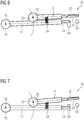
- Outlined for this Figure 6 an example in which the main contact arm 11 is pivoted further into an operating position. In this regard, it is irrelevant whether, for the normal state of the power line, the main contact arm 11 is pivoted into the operating position sketched here or back into the starting position.
- contact of the main contact 14 with the main counter bearing 04 is independent of the position of the main contact arm 11 from the position shown in FIG Fig. 6 outlined operating position up to in Fig. 1 given starting position sketched.
- the outlines Figure 7 a solution in which the secondary contact arm 21 is pivoted further into a distortion.
- the secondary contact 55 with the flow element 57, 58 arranged thereon is now formed in this exemplary embodiment by a flow element part 57 arranged on the top and a flow element part 58 arranged on the underside.
- the shovel-like shape is advantageous of the flow element 57, 58 can be seen, which 57, 58 extends from near the end of the secondary contact 55 to the secondary contact arm 51.
- the second embodiment of the switching arrangement 31 is now sketched in the starting position or contact position.
- the main contact arm 41 can be seen, which is mounted 41 so as to be pivotable about the main longitudinal axis 42 via the main pivot bearing 43.
- the secondary pivot bearing 53 with a secondary pivot axis 52 parallel to the main pivot axis 42 is arranged on the main contact arm 41 at a distance from the main pivot axis 42.
- the secondary contact arm 51 which 51 has a joint 56, is fastened to the secondary pivot axis 53.
- the axis of the joint 56 is oriented perpendicular to the secondary pivot axis 52 and transversely to the longitudinal extension of the secondary contact arm 51.
- the secondary contact 55 is located on the top and bottom of the flow element 57, 58 as in the previous one Figure 8 is arranged shown in detail. In this case, the secondary contact 55 rests against the stationary secondary abutment 35 in the contact position.
- the deflecting element 36 is arranged diagonally above the secondary thrust bearing 35 opposite the secondary contact 55, over which the secondary contact 55 with the part of the flow element 58 located on the underside slides when the arrangement with the main contact arm 41 and the secondary contact arm 51 is pivoted back and thus over the secondary thrust bearing 35 is led away.
- the switching arrangement 31 is sketched in the pivoting movement from the starting position into the intermediate position.
- the main contact 44 is located at a distance from the main thrust bearing 34.
- the secondary contact 55 rests on the secondary thrust bearing 35 undiminished.
- the switching arrangement 31 is sketched in the intermediate position of the main contact arm 41 and thus at the same time the limit position of the secondary contact arm 51.
- the contact of the secondary contact 55 is released from the secondary counter bearing 35 so that the subsequent movement
- the secondary contact arm 51 is pulled to the main contact arm 41 in an accelerated manner.
- an air flow onto the free end of the secondary contact 55 is brought about.
- a resulting arc is extinguished more quickly.
Landscapes
- Multiple-Way Valves (AREA)
- Contacts (AREA)
Abstract
Description
- Die Erfindung betrifft eine Schaltanordnung zum Trennen einer stromführenden Verbindung, wobei an einem feststehenden Kontakt, dem Nebengegenlager ein Nebenkontakt anliegt. Der Nebenkontakt ist hierbei am Ende eines schwenkbaren Nebenkontaktarms angeordnet und ein Schwenken bewirkt die Trennung der leitenden Verbindung.
- Aus dem Stand der Technik sind verschiedene Schaltanordnungen bekannt, bei denen mittels eines schwenkbaren Bauteils eine Trennung der stromleitenden Verbindung bewirkt werden kann. Eine bekannte Ausführungsform, welche der Erfindung zu Grunde liegt, ist aus der
DE 16 65 510 C3 bekannt. - Der offenbarte Hochspannungsschalter weist eine um eine Achse drehbaren Hauptstrombahn auf, welche mit seinem freien Ende in der stromführenden Stellung an einem feststehenden Hauptkontakt anliegt. Auf der Hauptstrombahn ist eine Nebenstrombahn schwenkbar gelagert, wobei die Schwenkachse der Nebenstrombahn geringfügig parallel versetzt zur Schwenkachse der Hauptstrombahn angeordnet ist. Neben dem feststehenden Hauptkontakt ist ein feststehender Nebenkontakt vorhanden, an dem die Nebenstrombahn in stromführender Stellung anliegt. Hierzu ist in der Lagerung der Nebenstrombahn eine Feder angeordnet, welche die Anlage am feststehenden Nebenkontakt bewirkt. Beim Drehen der Hauptstrombahn und damit dem Öffnen der Verbindung vom feststehenden Hauptkontakt wird die Feder gespannt, da die Nebenstrombahn weiterhin am feststehenden Nebenkontakt anliegt und somit an gleicher Schwenkbewegung gehindert wird. Kurz vor dem Erreichen der Endstellung der Hauptstrombahn gleitet die Nebenstrombahn am feststehenden Nebenkontakt vorbei und die Nebenstrombahn wird von der gespannten Feder in die vorherige Stellung relativ zur Hauptstrombahn gezogen. Dabei wird die Verbindung zum feststehenden Nebenkontakt unterbrochen. Somit wird beim Schaltvorgang zunächst eine lichtbogenfreie Trennung vom Hauptkontakt ermöglicht. Anschließend erfolgt erst die Trennung vom feststehenden Nebenkontakt.
- Wenngleich die über den feststehenden Nebenkontakt geleiteten Ströme beim Schaltvorgang geringer sind und somit der beim Trennen auftretende Lichtbogen geringer ist als es dieser bei einem einzelnen Hauptschalter wäre, so führt jeder Schaltvorgang mit dem entstehenden Lichtbogen zu einer Schädigung des feststehenden Nebenkontaktes bzw. der Nebenstrombahn.
- Aufgabe der vorliegenden Erfindung ist es daher das Auftreten von Lichtbögen beim Schaltvorgang zu verringern.
- Die gestellte Aufgabe wird durch eine erfindungsgemäße Ausführungsform einer Schaltanordnung nach der Lehre des Anspruchs 1 gelöst. Vorteilhafte Ausführungsformen sind Gegenstand der Unteransprüche.
- Die gattungsgemäße Schaltanordnung dient insbesondere zum Trennen einer elektrisch leitenden Verbindung und umfasst zunächst einmal ein feststehendes Nebengegenlager sowie einen bewegbaren Nebenkontaktarm. Der Nebenkontaktarm liegt hierbei in einer Kontaktstellung mit einem am freien Ende angeordneten Nebenkontakt am Nebengegenlager an und stellt somit die stromführende Verbindung der Schaltanordnung her.
- Der Nebenkontaktarm weist hierbei am zum Nebenkontakt gegenüberliegenden Ende eine Nebenschwenkachse auf, um die der Nebenkontaktarm schwenkbar ist. Hierbei ist vorgesehen, dass der Nebenkontaktarm zumindest ausgehend von einer Kontaktstellung bei einer Anlage des Nebenkontaktes am Nebengegenlager um die Nebenschwenkachse in einer ersten Richtung bis zu einer Grenzstellung und in entgegengesetzter Richtung zurück bis in eine Ruhestellung schwenkbar ist.
- Hierbei ist es möglich, dass die Ruhestellung mit der Kontaktstellung übereinstimmt.
- Gleichfalls ist der Nebenkontaktarm quer zur Nebenschwenkachse verstellbar. Dabei ist es möglich, eine geradlinige Verstellbewegung quer zur Nebenschwenkachse und beispielsweise ungefähr quer zu einer Erstreckung des Nebenkontaktarms, wenn sich dieser in der Ausgangsstellung befindet, vorzusehen. Diesbezüglich ist jedoch hervorzuheben, dass die Verstellbarkeit quer zur Nebenschwenkachse neben einer Verschiebung gleichfalls ein Schwenken beinhalten kann und sich die Verstellbewegung insofern aus einer Translation und einer Rotation zusammensetzt. Die Verstellbewegung quer zur Nebenschwenkachse erfolgt hierbei von einer Ausgangsstellung über eine Zwischenstellung bis in eine Freistellung.
- Dabei ist vorzusehen, dass mit einer Verstellung des Nebenkontaktarms von der Ausgangsstellung zur Zwischenstellung zugleich ein Schwenken von der Kontaktstellung zur Grenzstellung erfolgt. Damit befindet sich der Nebenkontaktarm bei Erreichen der Zwischenstellung zugleich in der Grenzstellung. Die gleichzeitige Verstellung wird hierbei durch die von der Kontaktstellung bis zur Grenzstellung gegebene Anlage des Nebenkontaktes am Nebengegenlager bewirkt. D.h. die Verstellbewegung ist ohne gleichzeitiges Schwenken nicht möglich.
- Hinsichtlich der Positionierung des Nebenkontaktes relativ zum Nebengegenlager in der Ausgangsstellung kann einerseits vorgesehen sein, dass sich der Nebenkontaktarm in der Kontaktstellung befindet und der Kontakt vom Nebenkontakt zum Nebengegenlager gegeben ist.
- Alternativ kann vorgesehen sein, dass der Nebenkontakt in der Ausgangsstellung beabstandet zum Nebengegenlager angeordnet ist und sich somit nicht in der Kontaktstellung befindet. In diesem Fall wird die Kontaktstellung bei einem anteilig kurzen Wegstück von der Ausgangsstellung zur Zwischenstellung erreicht. Ein anteilig kurzes Wegstück wird bei weniger als 10% des Weges angenommen. In diesem Fall befindet sich der Nebenkontaktarm in der Ausgangsstellung zugleich in der Ruhestellung.
- Bei einer weiteren Verstellung von der Zwischenstellung in Richtung der Freistellung entfernt sich der Nebenkontakt zunehmend vom Nebengegenlager und der stromführende Kontakt wird unterbrochen. Zugleich schwenkt der Nebenkontaktarm zurück, so dass kurz vor, mit oder kurz nach dem Erreichen der Freistellung der Nebenkontaktarm mit der gleichzeitigen Schwenkbewegung um die Nebenschwenkachse in die Ruhestellung gelangt.
- Mit dem Ablösen des Nebenkontaktes vom Nebengegenlager in der Zwischenstellung/Grenzstellung tritt üblicherweise (in Abhängigkeit von den anliegenden Spannungen und Strömen) ein Lichtbogen zwischen dem Nebenkontakt und dem Nebengegenlager auf. Zur Reduzierung dieses Effektes bzw. Reduzierung der Dauer des Lichtbogens ist erfindungsgemäß vorgesehen, dass am Nebenkontaktarm zumindest im Bereich des Nebenkontaktes ein Strömungselement angeordnet wird. Dabei ist das Strömungselement derart auszuführen, dass bei einem Schwenken des Nebenkontaktarms um die Nebenschwenkachse eine Luftströmung auf das freie Ende des Nebenkontaktes und somit auf den Lichtbogen bewirkt wird. Hierzu stellt das Strömungselement ein Luftwiderstand gegen die Schwenkbewegung dar, wobei die vom Strömungselement beim Schwenken verdrängte Luft entsprechend möglichst auf das Ende des Nebenkontaktes zu leiten ist (und möglichst nicht beabstandet vom freien Ende über oder unter dem Nebenkontakt vorbeiströmt).
- Durch die erfindungsgemäße Anordnung eines Strömungselements am schwenkbaren Nebenkontakt wird beim Trennen der Verbindung zum Nebengegenlager eine Luftströmung auf den entstehenden Lichtbogen bewirkt, welcher hierdurch schneller erlischt. Dieses führt zu einer geringeren Schädigung der Schaltanordnung als es bei einer gattungsgemäßen Ausführung der Fall ist. Im Umkehrschluss wird hierdurch die zulässige Spannung bzw. der zulässige Strom beim Trennvorgang erhöht und somit erweitert sich der Anwendungsbereich der jeweiligen Ausführung gegenüber der gattungsgemäßen Lösung.
- Das Strömungselement soll bestimmungsgemäß einen Luftstrom auf das freie Ende des Nebenkontaktarms leiten. Insofern ist eine Anordnung erforderlich, die wirksam ist um entsprechende Luftbewegung abweichend von einer Ausführung ohne Strömungselement bewirken zu können. Diesbezüglich wird in einer ersten vorteilhaften Ausführungsform das Strömungselement auf einer in Richtung der Nebenschwenkachse liegenden Seite am Nebenkontakt angeordnet. Besonders vorteilhaft ist es jedoch, wenn das Strömungselement beidseitig in Richtung der Nebenschwenkachse am Nebenkontakt angeordnet ist. Diesbezüglich ist es unerheblich, ob das Strömungselement von einem Bauteil gebildet wird oder mehrteilig ausgeführt ist.
- Eine vorteilhafte Verdrängung der Luft beim Schwenken des Nebenkontaktarms wird erzielt, wenn das Strömungselement auf der in Kontaktstellung zum Nebengegenlager weisenden Seite eine flache und/oder schaufelartige Gestalt aufweist. Hierbei erstreckt sich folglich das Strömungselement in Längsrichtung des Nebenkontaktarms sowie in Richtung der Nebenschwenkachse. Somit kann die Luft beim Schwenken des Nebenkontaktarms vorteilhaft in Längsrichtung des Nebenkontaktarms auf das freie Ende des Nebenkontaktes geleitet werden.
- Zur Gewährleistung des vorgesehenen Stromflusses vom Nebenkontakt zum Nebengegenlager unter Vermeidung undefinierter Stromflüsse ist das Strömungselement in vorteilhafter Weise aus einem nicht leitenden Material hergestellt.
- Eine besonders vertrackte Gestaltung des Strömungselements wird erzielt, wenn dieses eine hinreichende wirksame Größe aufweist demgegenüber jedoch nicht unnötig die Schwenkbewegung aufgrund des Luftwiderstandes behindert. Hierzu wird die bei einer Schwenkbewegung entgegenstehende wirksame Widerstandsfläche FS betrachtet, d.h. bei einer rechteckigen Gestalt die Fläche gebildet von dem Produkt aus der Länge in Richtung der Längsrichtung des Nebenkontaktarms multipliziert mit der wirksamen Breite in Richtung der Nebenschwenkachse. Zum Verhältnis wird hierzu eine Nebenarmlänge LN als der Abstand von der Nebenschwenkachse bis zum Ende des Nebenkontaktes betrachtet. Wenngleich der Nebenkontakt nur einen geringfügigen Beitrag liefert, so wird dieser, insofern sich das Strömungselement im Bereich des Nebenkontaktes befindet, in die Berücksichtigung der wirksamen Widerstandsfläche FS mit einbezogen.
Hierbei ergibt sich in vorteilhafter Weise eine
Widerstandsfläche FS gemäß der Formel:


Widerstandsfläche höchstens:
- Ein Strömungselement in dieser Größenordnung stellt einen besonders vorteilhaften Kompromiss zwischen der gewünschten Luftströmung auf das freie Ende des Nebenkontaktes zur Bekämpfung eines Lichtbogens unter Vermeidung eines unnötigen Luftwiderstandes zur Gewährleistung einer schnellen Schwenkbewegung dar.
- Zur Realisierung der Schwenkbewegung des Nebenkontaktarms weist die Schaltanordnung in bevorzugter Ausführung ein Nebenschwenklager auf, an dem der Nebenkontaktarm schwenkbar gelagert ist. Somit definiert das Nebenschwenklager die Nebenschwenkachse.
- Gattungsgemäß ist vorgesehen, dass bei Überschreiten der Zwischenstellung ein unmittelbares Zurückschwenken des Nebenkontaktarms erfolgt. Hierzu wird in bevorzugter Ausführung eine Spannvorrichtung eingesetzt, welche bei einem Schwenken des Nebenkontaktarms ausgehend von der Kontaktstellung in die Grenzstellung gespannt wird. Erfolgt das Überschreiten der Grenzstellung aufgrund der Bewegung über die Zwischenstellung hinaus bewirkt die Spannvorrichtung das Zurückschwenken des Nebenkontaktarms.
- Die Spannvorrichtung kann hierbei unterschiedlich ausgeführt sein, wobei in bevorzugter Ausführung diese im und/oder am Nebenschwenklager angeordnet wird. Beispielsweise kann eine Drehfeder eingesetzt werden.
- Um erneut einen Kontakt herstellen zu können, ist es erforderlich, den Nebenkontakt am Nebengegenlager in der entgegengesetzten Richtung vorbei führen zu können. Da in der Regel vorgesehen ist, dass sich der Nebenkontaktarm nicht über die Ruhestellung hinaus schwenken lässt, würde die Rückführung der Verstellbewegung von der Freistellung in die Ausgangsstellung zu einer Kollision führen. Daher ist vorteilhafte vorgesehen, dass am Nebengegenlager ein Ablenkelement angeordnet ist. Hierzu ist es erforderlich, dass der Nebenkontaktarm entweder einen elastischen Verformungsbereich oder ein Knickgelenk aufweist, welcher bzw. welches eine Verstellung des Nebenkontakt des in Richtung der Nebenschwenkachse über das Nebengegenlager ermöglicht. Insofern ist eine Gelenksachse des Knickgelenks senkrecht zur Nebenschwenkachse auszurichten. Hierbei hat das Ablenkelement die Aufgabe den Nebenkontakt bei der Bewegung in die Ausgangsstellung über das Nebengegenlager hinweg zu führen.
- Da das Ablenkelement sowie das erfindungsgemäße Strömungselement im Bereich des Nebenkontaktes angeordnet sind, ist vorteilhaft vorgesehen, dass das Strömungselement abschnittsweise bei entsprechender Verstellbewegung zurück in die Ausgangsstellung auf dem Ablenkelement zur Auflage kommt. Es kann jedoch auch vorgesehen sein, dass das Strömungselement so ausgeführt wird, dass der Nebenkontakt unmittelbar auf dem Ablenkelement zur Auflage kommt.
- Um sicherzustellen, dass mit dem Ende der Verstellbewegung zurück zur Ausgangsstellung der Nebenkontakt nicht am Ablenkelement hängen bleibt, ohne dass dieser die Kontaktstellung einnehmen kann, ist es weiterhin vorteilhaft, wenn entweder der Nebenkontaktarm über die Ausgangsstellung hinaus bis in eine Betriebsstellung verstellbar oder alternativ über die Kontaktstellung hinaus bis in eine Endstellung schwenkbar ist. In beiden Fällen wird somit ermöglicht, dass der Nebenkontakt nach dem Überqueren des Ablenkelements in Richtung der Nebenschwenkachse in die Kontaktstellung zurückkehren kann. Auf jeden Fall ist hierbei sicherzustellen, dass der Hauptkontakt von der Betriebsstellung bis zur Ausgangsstellung zuverlässig Kontakt zum Hauptgegenlager besitzt.
- Wenngleich der schaltbare Nebenkontakt als eigenständige Schaltanordnung Verwendung finden kann, so ist besonders vorteilhaft eine Kombination eines Hauptkontaktes mit dem Nebenkontakt in einer Schaltanordnung zu verwenden. Diese vorteilhafte Schaltanordnung weist zunächst einmal einen Hauptkontaktarm auf, welcher an einem freien Ende den Hauptkontakt umfasst. Am vom Hauptkontakt gegenüberliegenden Ende befindet sich eine Hauptschwenkachse, um die der Hauptkontaktarm von der Ausgangsstellung über die Zwischenstellung bis in die Freistellung schwenkbar ist. Dabei ist die Nebenschwenkachse parallel beanstandet zur Hauptschwenkachse am Hauptkontaktarm angeordnet.
- Entsprechend führt ein Schwenken des Hauptkontaktarms zu einer gleichzeitigen Verstellung des Nebenkontaktarms quer zur Nebenschwenkachse aufgrund der Verstellung der Nebenschwenkachse. Zugleich führt die Anlage des Nebenkontakts am Nebengegenlager von der Kontaktstellung bis zur Grenzstellung zu einem zum Hauptkontaktarm gegenläufigen Schwenken um die Nebenschwenkachse.
- In der Ausgangsstellung liegt der Hauptkontakt an einem Hauptgegenlager an. Das Hauptgegenlager ist hierbei benachbart zum Nebengegenlager gleichfalls feststehend angeordnet. Beim Schwenken des Hauptkontaktarms entfernt sich der Hauptkontakt vom Hauptgegenlager. Hierzu weist die Schaltanordnung zusätzlich zum Nebengegenlager ein gleichfalls feststehendes, benachbart angeordnetes Hauptgegenlager auf.
- Dabei ist vorgesehen, dass bereits ein hinreichender Abstand zwischen dem Hauptkontakt und dem Hauptgegenlager bei Erreichen der Zwischenstellung bzw. bezüglich des Nebenkontaktarm der Grenzstellung vorhanden ist, sodass kein Lichtbogen zwischen dem Hauptkontakt und dem Hauptgegenlager auftreten kann.
- Zur Lagerung des Hauptkontaktarms ist es vorteilhaft, wenn ein Hauptschwenklager eingesetzt wird, mittels dem der Hauptkontaktarm schwenkbar gelagert ist und welcher somit die Hauptschwenkachse definiert.
- Ein besonders vorteilhafter Aufbau hinsichtlich der Anordnung des Nebenkontaktarm am Hauptkontaktarm wird durch die Anordnung des Nebenschwenklagers am Hauptkontaktarm erreicht.
- In den nachfolgenden Figuren werden zwei beispielhafte Ausführungen für eine Schaltanordnung skizziert. Es zeigen:
- Fig. 1
- ein erstes Ausführungsbeispiel mit der Schaltanordnung in der Ausgangsstellung sowie Zwischenstellung;
- Fig. 2
- die Schaltanordnung aus
Fig. 1 in der Bewegung zur Zwischenstellung / Grenzstellung; - Fig. 3
- die Schaltanordnung aus
Fig. 1 in der Zwischenstellung / Grenzstellung; - Fig. 4
- die Schaltanordnung aus
Fig. 1 in der Bewegung von der Zwischenstellung / Grenzstellung in die Freistellung / Ruhestellung; - Fig. 5
- die Schaltanordnung aus
Fig. 1 in der Freistellung / Ruhestellung; - Fig. 6
- die Schaltanordnung aus
Fig. 1 in der Bewegung zur Betriebsstellung; - Fig. 7
- die Schaltanordnung aus
Fig. 1 in der Bewegung zur Endstellung; - Fig. 8
- zu einem zweiten Ausführungsbeispiel der Nebenkontakt mit Strömungselement im Detail;
- Fig. 9
- das zweite Ausführungsbeispiel in der Ausgangsstellung / Kontaktstellung;
- Fig. 10
- die Schaltanordnung aus
Fig. 9 in der Bewegung zur Zwischenstellung / Grenzstellung; - Fig. 11
- die Schaltanordnung aus
Fig. 9 in der Zwischenstellung / Grenzstellung. - In der
Figur 1 wird in einer Draufsicht in Richtung der Nebenschwenkachse 22 das erste Ausführungsbeispiel einer erfindungsgemäßen Schwenkanordnung 01 schematisch skizziert. Zu erkennen ist der Hauptkontaktarm 11, welcher 11 mit dem Hauptschwenklager 13 um die Hauptschwenkachse 12 schwenkbar gelagert ist. Am von der Hauptschwenkachse 12 gegenüberliegenden Ende des Hauptschwenkarms 11 befindet sich ein Hauptkontakt 14. Dieser 14 liegt auf einem feststehenden Hauptgegenlager 04 und somit stellt diese Verbindung die für den Regelfall vorgesehene leitende Verbindung her. - In dieser Darstellung befindet sich der Hauptkontaktarm 11 in der Ausgangsstellung.
- Auf dem Hauptkontaktarm 11 befindet sich beabstandet zur Hauptschwenkachse 12 ein Nebenschwenklager 23 mit der Nebenschwenkachse 22, welche 22 parallel zur Hauptschwenkachse 12 ausgerichtet ist. Mit dem Nebenschwenklager 23 ist ein Nebenschwenkarm 21 verbunden, welcher 21 entsprechend um die Nebenschwenkachse 22 schwenkbar ist. Mit der Verbindung über das Nebenschwenklager 23 mit dem Hauptkontaktarm 11 führt dessen Schwenken zugleich zu einer Verschiebung des Nebenschwenklagers 23. Am zur Nebenschwenkachse 22 gegenüberliegenden Ende des Nebenkontaktarms 21 ist ein Nebenkontakt 25 angeordnet, welcher 25 an einem feststehenden Nebengegenlager 05 anliegt.
- Weiterhin befindet sich der Nebenkontaktarm 21 in dieser Darstellung in der Kontaktstellung.
- Weiterhin dargestellt wird in dieser Ansicht die Anordnung einer Spannvorrichtung 24, welche 24 den Nebenkontaktarm 21 mit dem Hauptkontaktarm 11 verbindet.
- Wesentlich für die vorliegende Erfindung ist die Anordnung eines Strömungselements 27 am Nebenkontakt 25. Entsprechend der Darstellung in
Fig. 1 befindet sich das Strömungselement 27 oberhalb des Nebenkontakts 25 und erstreckt sich in Richtung der Nebenschwenkachse 22. - In der
Figur 2 wird nunmehr die Schaltanordnung 01 aus derFig. 1 in der Bewegung des Hauptkontaktarms 11 zur Zwischenstellung skizziert. Zu erkennen ist der nunmehr vorhandene Abstand zwischen dem Hauptkontakt 14 und dem Hauptgegenlager 04. Demgegenüber liegt der Nebenkontakt 25 unvermindert am Nebengegenlager 05 an und blockiert somit die gleichartige Bewegung des Nebenkontaktarms 21. Aufgrund dessen erfährt das Nebenschwenklager 23 mit dem Nebenkontaktarm 21 einerseits eine Verschiebung auf dem Hauptkontaktarm 11 und anderseits erfolgt ein zum Hauptkontaktarm 11 gegenläufiges Schwenken um die Nebenschwenkachse 22. Dabei erfolgt ein Spannen der Spannvorrichtung 24. - In der
Figur 3 wird nunmehr die Zwischenstellung des Hauptkontaktarms 11 und somit des Nebenschwenklagers 23 skizziert, in der sich zugleich der Nebenkontaktarm 11 in der Grenzstellung befindet. Dieses stellt den Übergang da, bis zu dem der Nebenkontakt 25 am Nebengegenlager 05 anliegt. Da mit weiterer Schwenkbewegung des Hauptkontaktarms 11 keine Anlage des Nebenkontaktes 25 am Nebengegenlager 25 gegeben ist erfolgt aufgrund der gespannten Spannvorrichtung 24 ein unvermitteltes Zurückziehen des Nebenkontaktarms 21 zum Hauptkontaktarm 11, wobei sich der Abstand zwischen Nebenkontakt 25 und Nebengegenlager 05 mit - gegenüber dem Abstand vom Hauptkontakt 14 zum Hauptgegenlager 04 - erhöhter Geschwindigkeit vergrößert. - Bei Ablösung des Kontaktes entsteht in vielen Fällen ein Lichtbogen zwischen dem Nebenkontakt 25 und dem Nebengegenlager 25, den es zu eliminieren bzw. zumindest zu reduzieren gilt. Dieses wird mit Hilfe des Strömungselementes bewirkt, welches mit der einsetzenden Schwenkbewegung des Nebenkontaktarms 11 nach Verlassen der Grenzstellung eine Luftströmung auf das freie Ende des Nebenkontakts 25 bewirkt. Der entstehende Lichtbogen wird sozusagen ausgeblasen.
- In der nachfolgenden
Figur 4 wird die Schwenkanordnung 01 in der weiteren Bewegung mit dem Hauptkontaktarm 11 zwischen der Zwischenstellung und der Freistellung und dem Nebenkontaktarm 21 zwischen der Grenzstellung und der Ruhestellung skizziert. - In der
Figur 5 wird exemplarisch die Schwenkanordnung 01 in der Freistellung zugleich Ruhestellung skizziert. - Nicht dargestellt ist in diesem Ausführungsbeispiel das vorteilhafte Ablenkungselement, welches in der Schwenkbewegung zurück aus der Freistellung in die Ausgangsstellung das Passieren des Nebenkontaktes 25 am Nebengegenlager 05 ermöglicht. Um sicherzustellen, dass der Nebenkontakt 25 nicht am Ablenkelement am Ende der Bewegung hängenbleibt und somit nicht in seine Kontaktstellung zurückkehren kann wird der Nebenkontakt bis über das Ablenkelement hinausgeführt. Hierzu skizziert
Figur 6 ein Beispiel, bei dem der Hauptkontaktarm 11 bis in eine Betriebsstellung weiter geschwenkt wird. Diesbezüglich ist es unerheblich, ob für den Normalzustand der Stromleitung der Hauptkontaktarm 11 in der hier skizzierten Betriebsstellung oder wieder in die Ausgangsstellung geschwenkt wird. Hier ist in jedem Fall ein Kontakt des Hauptkontaktes 14 zum Hauptgegenlager 04 unabhängig von der Stellung des Hauptkontaktarms 11 von der inFig. 6 skizzierten Betriebsstellung bis zur inFig. 1 skizzierten Ausgangsstellung gegeben. Alternativ hierzu skizziert dieFigur 7 eine Lösung, bei der der Nebenkontaktarm 21 weiter bis in eine Entstellung geschwenkt wird. - In der
Figur 8 wird nunmehr für ein weiteres Ausführungsbeispiel einer erfindungsgemäßen Schaltanordnung 31 der Nebenkontakt 55 mit dem daran angeordneten Strömungselement 57, 58 gebildet in diesem Ausführungsbeispiel von einem an der Oberseite angeordneten Strömungselementteil 57 sowie einem an der Unterseite angeordneten Strömungselementteil 58. In dieser Figur ist vorteilhaft die schaufelartige Gestalt des Strömungselements 57, 58 zu erkennen, welches 57, 58 sich von nahe dem Ende des Nebenkontaktes 55 bis auf den Nebenkontaktarm 51 erstreckt. - In der
Figur 9 ist nunmehr das zweite Ausführungsbeispiel der Schaltanordnung 31 in der Ausgangsstellung bzw. Kontaktstellung skizziert. Zu erkennen ist zunächst einmal der Hauptkontaktarm 41, welcher 41 über das Hauptschwenklager 43 um die Hauptlängsachse 42 schwenkbar gelagert ist. - Gegenüberliegend befindet sich der Hauptkontakt 44, welcher 44 auf dem feststehenden Hauptgegenlager 34 in der hier dargestellten Ausgangsstellung aufliegt.
- Auf dem Hauptkontaktarm 41 ist beanstandet zur Hauptschwenkachse 42 das Nebenschwenklager 53 mit einer Nebenschwenkachse 52 parallel zur Hauptschwingachse 42 angeordnet. Am Nebenschwenkachse 53 ist der Nebenkontaktarm 51 befestigt, welcher 51 über ein Gelenk 56 verfügt. Die Achse des Gelenks 56 ist hierbei senkrecht zur Nebenschwenkachse 52 und quer zur Längserstreckung des Nebenkontaktarms 51 ausgerichtet. Am Ende des Nebenkontaktarms 51 befindet sich der Nebenkontakt 55 an dessen Oberseite und Unterseite sich das Strömungselement 57,58 wie in der vorherigen
Figur 8 im Detail dargestellt angeordnet ist. Der Nebenkontakt 55 liegt hierbei in der Kontaktstellung an dem feststehenden Nebengegenlager 35 an. - Schräg oberhalb des Nebengegenlager 35 gegenüberliegend zum Nebenkontakt 55 ist das Ablenkelement 36 angeordnet, über dem 36 beim Zurückschwenken der Anordnung mit dem Hauptkontaktarm 41 und dem Nebenkontaktarm 51 der Nebenkontakt 55 mit dem an der Unterseite angeordneten Teil des Strömungselements 58 hinweggleitet und somit über das Nebengegenlager 35 hinweg geführt wird.
- In der nachfolgenden
Figur 10 wird die Schaltanordnung 31 in der Schwenkbewegung von der Ausgangsstellung in die Zwischenstellung skizziert. Hierbei befindet sich der Hauptkontakt 44 beanstandet zum Hauptgegenlager 34. demgegenüber liegt unvermindert der Nebenkontakt 55 am Nebengegenlager 35 an. - In der
Figur 11 wird die Schaltanordnung 31 in der Zwischenstellung des Hauptkontaktarm 41 und somit zugleich der Grenzstellung des Nebenkontaktarms 51 skizziert. In diesem Zustand löst sich der Kontakt des Nebenkontakts 55 vom Nebengegenlager 35 sodass in nachfolgender Bewegung der Nebenkontaktarm 51 beschleunigt zum Hauptkontaktarm 41 gezogen wird. Mit der einsetzenden Bewegung und der Anordnung des Strömungselements 57,58 am Nebenkontakt 55 wird eine Luftströmung auf das freie Ende des Nebenkontakt 55 bewirkt. Hierdurch wird ein entstehender Lichtbogen beschleunigt ausgelöscht.
Claims (14)
- Schaltanordnung (01,31), insbesondere zum Trennen einer elektrisch leitenden Verbindung,
mit einem feststehenden Nebengegenlager (05,35) und
mit einem Nebenkontaktarm (21,51), welcher (21,51) an einem Ende einen Nebenkontakt (25,55) umfasst und um eine am gegenüberliegenden Ende angeordnete Nebenschwenkachse (22, 52) von einer Kontaktstellung zu einer Grenzstellung und zurück zu einer Ruhestellung schwenkbar und quer zur Nebenschwenkachse (22,52) von einer Ausgangsstellung über eine Zwischenstellung in eine Freistellung verstellbar ist,
wobei bei einer Verstellung von der Ausgangsstellung zur Zwischenstellung der Nebenkontakt (25,55) am Nebengegenlager (05,35) anliegt und ein Schwenken von der Kontaktstellung zur Grenzstellung erfolgt und
wobei bei einer Verstellung von der Zwischenstellung zur Freistellung ein Zurückschwenken von der Grenzstellung in die Ruhestellung erfolgt und der Nebenkontakt (25,55) zunehmend vom Nebengegenlager (05,35) beabstandet ist, dadurch gekennzeichnet,
dass der Nebenkontaktarm (21,51) ein Strömungselement (27,57,58) umfasst, welches (27,57,58) am Nebenkontakt (25, 55) angeordnet ist und beim Zurückschwenken eine Luftströmung auf das freie Ende des Nebenkontakts (25,55) bewirkt. - Schaltanordnung (01,31,31) nach Anspruch 1,
dadurch gekennzeichnet,
dass das Strömungselement (27,57,58) in Richtung der Nebenschwenkachse (22,52) beidseitig am Nebenkontakt (25, 55) angeordnet ist. - Schaltanordnung (01,31) nach Anspruch 1 oder 2,
dadurch gekennzeichnet,
dass das Strömungselement (27,57,58) zumindest auf derjenigen Seite, mit der der Nebenkontakt (25,55) am Nebengegenlager (05,35) anliegt, eine flache und/oder schaufelartige Gestalt aufweist und sich in einer Längsrichtung des Nebenkontaktarms (21,51) und in der Richtung der Nebenschwenkachse (22,52) erstreckt. - Schaltanordnung (01,31) nach einer der Ansprüche 1 bis 3,
dadurch gekennzeichnet,
dass das Strömungselement (27,57,58) aus einem nichtleitenden Material besteht. - Schaltanordnung (01,31) nach einer der Ansprüche 1 bis 4,
dadurch gekennzeichnet,
dass der Nebenkontaktarm (21,51) von der Nebenschwenkachse (22,52) bis zum Ende des Nebenkontaktes (25, 55) eine Nebenarmlänge LN und das Strömungselement (27,57,58) eine wirksame Widerstandsfläche FS von zumindest FS = 0,0005 * LN * LN, insbesondere von zumindest FS = 0,001 * LN * LN, und maximal von FS = 0,01 * LN * LN, insbesondere maximal von FS = 0,004 * LN * LN, aufweist. - Schaltanordnung (01,31) nach einer der Ansprüche 1 bis 5,
gekennzeichnet durch
ein Nebenschwenklager (23,53), mittels dem (23,53) der Nebenkontaktarm (21,51) schwenkbar gelagert ist und welches (23,53) die Nebenschwenkachse (22,52) definiert. - Schaltanordnung (01,31) nach einer der Ansprüche 1 bis 6,
gekennzeichnet durch
eine Spannvorrichtung (24), welche (24) beim Schwenken des Nebenkontaktarms (21,51) in die Grenzstellung gespannt wird und bei Überschreiten der Zwischenstellung das Zurückschwenken des Nebenkontaktarms (21,51) bewirkt. - Schaltanordnung (31) nach Anspruch 7,
dadurch gekennzeichnet,
dass die Spannvorrichtung in und/oder am Nebenschwenklager (53) angeordnet ist. - Schaltanordnung (01,31) nach einer der Ansprüche 1 bis 8,
dadurch gekennzeichnet,
dass am Nebengegenlager (05,35) ein Ablenkelement (36) angeordnet ist und der Nebenkontaktarm (21,51) einen elastischen Verformungsbereich (26) oder ein Knickgelenk (56) senkrecht zur Nebenschwenkachse (22,52) aufweist, wobei der Nebenkontakt (25,55) bei einer Verstellung in die Ausgangsstellung vom Ablenkelement (36) über das Nebengegenlager (05,35) hinweg geführt wird. - Schaltanordnung (01,31) nach Anspruch 9,
dadurch gekennzeichnet,
dass das Strömungselement (27,57,58) beim Zurückschwenken auf dem Ablenkelement (36) zur Anlage kommt. - Schaltanordnung (01,31) nach Anspruch 9 oder 10,
dadurch gekennzeichnet,
dass der Nebenkontaktarm (21,51) über die Ausgangsstellung hinaus bis in eine Betriebsstellung verstellbar und/oder über die Kontaktstellung hinaus bis in eine Endstellung schwenkbar ist. - Schaltanordnung (01,31) nach einer der Ansprüche 1 bis 11,
gekennzeichnet durch
ein feststehendes Hauptgegenlager (04,34) und
einen Hauptkontaktarm (11,41), welcher (11,41) an einem Ende ein Hauptkontakt (14,44) und am gegenüberliegenden Ende eine Hauptschwenkachse (12,42) umfasst und um die Hauptschwenkachse (12,42) von der Ausgangsstellung, insbesondere von der Betriebsstellung, über die Zwischenstellung bis in die Freistellung schwenkbar ist, wobei die Nebenschwenkachse (22,52) parallel beabstandet zur Hauptschwenkachse (12,42) am Hauptkontaktarm (11,41) angeordnet ist, und wobei der Hauptkontakt (14,44) in der Ausgangsstellung am Hauptgegenlager (04,34) anliegt und beim Schwenken in die Freistellung zunehmend vom Hauptgegenlager (04,34) beabstandet ist. - Schaltanordnung (01,31) nach Anspruch 12,
gekennzeichnet durch
ein Hauptschwenklager (13), mittels dem (13) der Hauptkontaktarm (11,41) schwenkbar gelagert ist und welches (13) die Hauptschwenkachse (12,42) definiert. - Schaltanordnung (01,31) nach Anspruch 13,
dadurch gekennzeichnet,
dass das Nebenschwenklager (23,53) auf dem Hauptkontaktarm (11,41) angeordnet ist.
Priority Applications (2)
| Application Number | Priority Date | Filing Date | Title |
|---|---|---|---|
| PL19213408.8T PL3832685T3 (pl) | 2019-12-04 | 2019-12-04 | Układ przełączania do rozdzielania połączenia przewodzącego |
| EP19213408.8A EP3832685B1 (de) | 2019-12-04 | 2019-12-04 | Schaltanordnung zum trennen einer leitenden verbindung |
Applications Claiming Priority (1)
| Application Number | Priority Date | Filing Date | Title |
|---|---|---|---|
| EP19213408.8A EP3832685B1 (de) | 2019-12-04 | 2019-12-04 | Schaltanordnung zum trennen einer leitenden verbindung |
Publications (3)
| Publication Number | Publication Date |
|---|---|
| EP3832685A1 true EP3832685A1 (de) | 2021-06-09 |
| EP3832685C0 EP3832685C0 (de) | 2025-01-29 |
| EP3832685B1 EP3832685B1 (de) | 2025-01-29 |
Family
ID=68771418
Family Applications (1)
| Application Number | Title | Priority Date | Filing Date |
|---|---|---|---|
| EP19213408.8A Active EP3832685B1 (de) | 2019-12-04 | 2019-12-04 | Schaltanordnung zum trennen einer leitenden verbindung |
Country Status (2)
| Country | Link |
|---|---|
| EP (1) | EP3832685B1 (de) |
| PL (1) | PL3832685T3 (de) |
Citations (4)
| Publication number | Priority date | Publication date | Assignee | Title |
|---|---|---|---|---|
| DE681105C (de) * | 1935-05-03 | 1939-09-14 | Fritz Driescher Sen | Hochspannungslastschalter mit Lichtbogenloeschung durch einen Luftstrom |
| CH341209A (de) * | 1954-09-03 | 1959-09-30 | Frobert Dipl Ing Michaelis | Druckluft-Leistungstrennschalter |
| DE1073061B (de) * | 1957-10-02 | 1960-01-14 | Feiten &. Guilleaume Carlswerk Aktiengesellschaft, Köln-Mülheim | Leistungstrennschalter mit Lichtbogenlöscheinrichtung |
| DE1665510C3 (de) | 1968-02-09 | 1980-11-27 | Ruhrtal Elektrizitaetsgesellschaft Hartig Gmbh & Co, 4300 Essen | Hochspannungsschalter für Freiluftaufstellung |
-
2019
- 2019-12-04 PL PL19213408.8T patent/PL3832685T3/pl unknown
- 2019-12-04 EP EP19213408.8A patent/EP3832685B1/de active Active
Patent Citations (4)
| Publication number | Priority date | Publication date | Assignee | Title |
|---|---|---|---|---|
| DE681105C (de) * | 1935-05-03 | 1939-09-14 | Fritz Driescher Sen | Hochspannungslastschalter mit Lichtbogenloeschung durch einen Luftstrom |
| CH341209A (de) * | 1954-09-03 | 1959-09-30 | Frobert Dipl Ing Michaelis | Druckluft-Leistungstrennschalter |
| DE1073061B (de) * | 1957-10-02 | 1960-01-14 | Feiten &. Guilleaume Carlswerk Aktiengesellschaft, Köln-Mülheim | Leistungstrennschalter mit Lichtbogenlöscheinrichtung |
| DE1665510C3 (de) | 1968-02-09 | 1980-11-27 | Ruhrtal Elektrizitaetsgesellschaft Hartig Gmbh & Co, 4300 Essen | Hochspannungsschalter für Freiluftaufstellung |
Also Published As
| Publication number | Publication date |
|---|---|
| PL3832685T3 (pl) | 2025-06-02 |
| EP3832685C0 (de) | 2025-01-29 |
| EP3832685B1 (de) | 2025-01-29 |
Similar Documents
| Publication | Publication Date | Title |
|---|---|---|
| DE102019103320B4 (de) | Relais | |
| DE102019103298A1 (de) | Relais | |
| EP3016122B1 (de) | Mehrpolige Schaltersicherungsanordnung für Sammelschienensysteme | |
| DE602005000144T2 (de) | Schwenkbarer Erdungsschalter mit direkter Einführung und einfacher Bewegung | |
| DE69701227T2 (de) | Elektrischer schalter | |
| EP4018466B1 (de) | Baugruppe für einen hochspannungs-leistungsschalter und entsprechender hochspannungs-leistungsschalter | |
| DE102008049789A1 (de) | Kontaktvorrichtung mit unterschiedlichen Kontaktkräften in unterschiedlichen Betriebszuständen | |
| DE3021598C2 (de) | Drucktastenschalter | |
| EP3832685B1 (de) | Schaltanordnung zum trennen einer leitenden verbindung | |
| EP0471893A2 (de) | Kontaktfedersatz für hohe elektrische Ströme | |
| EP0177437B1 (de) | Kontaktanordnung für einen Leistungsschalter mit stromabhängiger Öffnung | |
| DE3906786C2 (de) | ||
| DE60110595T2 (de) | Schalter mit vor- und hauptkontakten | |
| DE10048659A1 (de) | Schaltkontaktanordnung eines Niederspannungs-Leistungsschalter mit Kontaktkraftfedern | |
| DE69508483T2 (de) | Elektromagnetischer Auslöser für einen Niederspannungsschutzschalter | |
| EP1930930A1 (de) | Getriebe für elektrischen Leistungsschalter | |
| EP3576125B1 (de) | Hochspannungsleistungsschalter | |
| DE102019112683B3 (de) | Schaltgerät mit selbstreinigenden Kontakten | |
| DE102010024386B4 (de) | Übertragungselement zur Übertragung von Antriebsbewegungen auf einen Bewegkontaktanschlussbolzen eines Schaltgeräts | |
| DE19910172B4 (de) | Leistungsschalter mit strombegrenzender Öffnung von Schaltkontakten | |
| DE1964363A1 (de) | Elektrischer Lasttrennschalter | |
| EP0637831B1 (de) | Kontaktaufreisseinrichtung für Schutzschaltgeräte | |
| DE19831658A1 (de) | Elektromechanisches Schaltrelais (3/98) | |
| EP0391339A2 (de) | Hochspannungsschaltgerät | |
| DE19949493A1 (de) | Erdungsschalter |
Legal Events
| Date | Code | Title | Description |
|---|---|---|---|
| PUAI | Public reference made under article 153(3) epc to a published international application that has entered the european phase |
Free format text: ORIGINAL CODE: 0009012 |
|
| STAA | Information on the status of an ep patent application or granted ep patent |
Free format text: STATUS: THE APPLICATION HAS BEEN PUBLISHED |
|
| AK | Designated contracting states |
Kind code of ref document: A1 Designated state(s): AL AT BE BG CH CY CZ DE DK EE ES FI FR GB GR HR HU IE IS IT LI LT LU LV MC MK MT NL NO PL PT RO RS SE SI SK SM TR |
|
| STAA | Information on the status of an ep patent application or granted ep patent |
Free format text: STATUS: REQUEST FOR EXAMINATION WAS MADE |
|
| 17P | Request for examination filed |
Effective date: 20211125 |
|
| RBV | Designated contracting states (corrected) |
Designated state(s): AL AT BE BG CH CY CZ DE DK EE ES FI FR GB GR HR HU IE IS IT LI LT LU LV MC MK MT NL NO PL PT RO RS SE SI SK SM TR |
|
| RAP1 | Party data changed (applicant data changed or rights of an application transferred) |
Owner name: SIEMENS ENERGY GLOBAL GMBH & CO. KG |
|
| STAA | Information on the status of an ep patent application or granted ep patent |
Free format text: STATUS: EXAMINATION IS IN PROGRESS |
|
| RIC1 | Information provided on ipc code assigned before grant |
Ipc: H01H 1/62 20060101ALN20230405BHEP Ipc: H01H 1/42 20060101ALN20230405BHEP Ipc: H01H 33/12 20060101ALI20230405BHEP Ipc: H01H 33/91 20060101ALI20230405BHEP Ipc: H01H 31/28 20060101ALI20230405BHEP Ipc: H01H 31/02 20060101ALI20230405BHEP Ipc: H01H 33/04 20060101AFI20230405BHEP |
|
| 17Q | First examination report despatched |
Effective date: 20230503 |
|
| GRAP | Despatch of communication of intention to grant a patent |
Free format text: ORIGINAL CODE: EPIDOSNIGR1 |
|
| STAA | Information on the status of an ep patent application or granted ep patent |
Free format text: STATUS: GRANT OF PATENT IS INTENDED |
|
| RIC1 | Information provided on ipc code assigned before grant |
Ipc: H01H 1/62 20060101ALN20240725BHEP Ipc: H01H 1/42 20060101ALN20240725BHEP Ipc: H01H 33/12 20060101ALI20240725BHEP Ipc: H01H 33/91 20060101ALI20240725BHEP Ipc: H01H 31/28 20060101ALI20240725BHEP Ipc: H01H 31/02 20060101ALI20240725BHEP Ipc: H01H 33/04 20060101AFI20240725BHEP |
|
| INTG | Intention to grant announced |
Effective date: 20240807 |
|
| GRAS | Grant fee paid |
Free format text: ORIGINAL CODE: EPIDOSNIGR3 |
|
| GRAA | (expected) grant |
Free format text: ORIGINAL CODE: 0009210 |
|
| STAA | Information on the status of an ep patent application or granted ep patent |
Free format text: STATUS: THE PATENT HAS BEEN GRANTED |
|
| AK | Designated contracting states |
Kind code of ref document: B1 Designated state(s): AL AT BE BG CH CY CZ DE DK EE ES FI FR GB GR HR HU IE IS IT LI LT LU LV MC MK MT NL NO PL PT RO RS SE SI SK SM TR |
|
| REG | Reference to a national code |
Ref country code: GB Ref legal event code: FG4D Free format text: NOT ENGLISH |
|
| REG | Reference to a national code |
Ref country code: CH Ref legal event code: EP |
|
| REG | Reference to a national code |
Ref country code: DE Ref legal event code: R096 Ref document number: 502019012875 Country of ref document: DE |
|
| REG | Reference to a national code |
Ref country code: IE Ref legal event code: FG4D Free format text: LANGUAGE OF EP DOCUMENT: GERMAN |
|
| U01 | Request for unitary effect filed |
Effective date: 20250212 |
|
| U07 | Unitary effect registered |
Designated state(s): AT BE BG DE DK EE FI FR IT LT LU LV MT NL PT RO SE SI Effective date: 20250219 |
|
| PG25 | Lapsed in a contracting state [announced via postgrant information from national office to epo] |
Ref country code: RS Free format text: LAPSE BECAUSE OF FAILURE TO SUBMIT A TRANSLATION OF THE DESCRIPTION OR TO PAY THE FEE WITHIN THE PRESCRIBED TIME-LIMIT Effective date: 20250429 |
|
| PG25 | Lapsed in a contracting state [announced via postgrant information from national office to epo] |
Ref country code: ES Free format text: LAPSE BECAUSE OF FAILURE TO SUBMIT A TRANSLATION OF THE DESCRIPTION OR TO PAY THE FEE WITHIN THE PRESCRIBED TIME-LIMIT Effective date: 20250129 |
|
| PG25 | Lapsed in a contracting state [announced via postgrant information from national office to epo] |
Ref country code: NO Free format text: LAPSE BECAUSE OF FAILURE TO SUBMIT A TRANSLATION OF THE DESCRIPTION OR TO PAY THE FEE WITHIN THE PRESCRIBED TIME-LIMIT Effective date: 20250429 Ref country code: IS Free format text: LAPSE BECAUSE OF FAILURE TO SUBMIT A TRANSLATION OF THE DESCRIPTION OR TO PAY THE FEE WITHIN THE PRESCRIBED TIME-LIMIT Effective date: 20250529 |
|
| PG25 | Lapsed in a contracting state [announced via postgrant information from national office to epo] |
Ref country code: HR Free format text: LAPSE BECAUSE OF FAILURE TO SUBMIT A TRANSLATION OF THE DESCRIPTION OR TO PAY THE FEE WITHIN THE PRESCRIBED TIME-LIMIT Effective date: 20250129 |
|
| PG25 | Lapsed in a contracting state [announced via postgrant information from national office to epo] |
Ref country code: GR Free format text: LAPSE BECAUSE OF FAILURE TO SUBMIT A TRANSLATION OF THE DESCRIPTION OR TO PAY THE FEE WITHIN THE PRESCRIBED TIME-LIMIT Effective date: 20250430 |
|
| PG25 | Lapsed in a contracting state [announced via postgrant information from national office to epo] |
Ref country code: SM Free format text: LAPSE BECAUSE OF FAILURE TO SUBMIT A TRANSLATION OF THE DESCRIPTION OR TO PAY THE FEE WITHIN THE PRESCRIBED TIME-LIMIT Effective date: 20250129 |
|
| PG25 | Lapsed in a contracting state [announced via postgrant information from national office to epo] |
Ref country code: CZ Free format text: LAPSE BECAUSE OF FAILURE TO SUBMIT A TRANSLATION OF THE DESCRIPTION OR TO PAY THE FEE WITHIN THE PRESCRIBED TIME-LIMIT Effective date: 20250129 |
|
| PG25 | Lapsed in a contracting state [announced via postgrant information from national office to epo] |
Ref country code: SK Free format text: LAPSE BECAUSE OF FAILURE TO SUBMIT A TRANSLATION OF THE DESCRIPTION OR TO PAY THE FEE WITHIN THE PRESCRIBED TIME-LIMIT Effective date: 20250129 |
|
| PLBE | No opposition filed within time limit |
Free format text: ORIGINAL CODE: 0009261 |
|
| STAA | Information on the status of an ep patent application or granted ep patent |
Free format text: STATUS: NO OPPOSITION FILED WITHIN TIME LIMIT |
|
| REG | Reference to a national code |
Ref country code: CH Ref legal event code: L10 Free format text: ST27 STATUS EVENT CODE: U-0-0-L10-L00 (AS PROVIDED BY THE NATIONAL OFFICE) Effective date: 20251210 |
|
| 26N | No opposition filed |
Effective date: 20251030 |
|
| PGFP | Annual fee paid to national office [announced via postgrant information from national office to epo] |
Ref country code: PL Payment date: 20251107 Year of fee payment: 7 |
|
| U20 | Renewal fee for the european patent with unitary effect paid |
Year of fee payment: 7 Effective date: 20251223 |
|
| PG25 | Lapsed in a contracting state [announced via postgrant information from national office to epo] |
Ref country code: MC Free format text: LAPSE BECAUSE OF FAILURE TO SUBMIT A TRANSLATION OF THE DESCRIPTION OR TO PAY THE FEE WITHIN THE PRESCRIBED TIME-LIMIT Effective date: 20250129 |
|
| REG | Reference to a national code |
Ref country code: CH Ref legal event code: H13 Free format text: ST27 STATUS EVENT CODE: U-0-0-H10-H13 (AS PROVIDED BY THE NATIONAL OFFICE) Effective date: 20260723 |