EP3832291B1 - Permeable measuring cell for receiving measuring means - Google Patents
Permeable measuring cell for receiving measuring means Download PDFInfo
- Publication number
- EP3832291B1 EP3832291B1 EP21154581.9A EP21154581A EP3832291B1 EP 3832291 B1 EP3832291 B1 EP 3832291B1 EP 21154581 A EP21154581 A EP 21154581A EP 3832291 B1 EP3832291 B1 EP 3832291B1
- Authority
- EP
- European Patent Office
- Prior art keywords
- measurement
- measurement cell
- measuring
- radiation
- fluid
- Prior art date
- Legal status (The legal status is an assumption and is not a legal conclusion. Google has not performed a legal analysis and makes no representation as to the accuracy of the status listed.)
- Active
Links
- 238000005259 measurement Methods 0.000 claims description 69
- 230000005855 radiation Effects 0.000 claims description 30
- 239000012530 fluid Substances 0.000 claims description 29
- 230000005670 electromagnetic radiation Effects 0.000 claims description 13
- 238000001139 pH measurement Methods 0.000 claims description 8
- 238000009529 body temperature measurement Methods 0.000 claims description 4
- 230000003993 interaction Effects 0.000 claims description 4
- 230000000704 physical effect Effects 0.000 claims description 3
- 239000000126 substance Substances 0.000 claims description 3
- 229910052729 chemical element Inorganic materials 0.000 claims description 2
- 210000004027 cell Anatomy 0.000 description 60
- 210000005056 cell body Anatomy 0.000 description 4
- 230000008878 coupling Effects 0.000 description 4
- 238000010168 coupling process Methods 0.000 description 4
- 238000005859 coupling reaction Methods 0.000 description 4
- 238000000034 method Methods 0.000 description 4
- 230000008569 process Effects 0.000 description 4
- 230000008859 change Effects 0.000 description 3
- 239000000463 material Substances 0.000 description 3
- 238000007789 sealing Methods 0.000 description 3
- 230000008901 benefit Effects 0.000 description 2
- 238000004140 cleaning Methods 0.000 description 2
- 238000009434 installation Methods 0.000 description 2
- 230000003287 optical effect Effects 0.000 description 2
- 238000004806 packaging method and process Methods 0.000 description 2
- 238000005192 partition Methods 0.000 description 2
- 230000009467 reduction Effects 0.000 description 2
- 238000004659 sterilization and disinfection Methods 0.000 description 2
- 238000004587 chromatography analysis Methods 0.000 description 1
- 238000011109 contamination Methods 0.000 description 1
- 230000001419 dependent effect Effects 0.000 description 1
- 238000001514 detection method Methods 0.000 description 1
- 238000011161 development Methods 0.000 description 1
- 230000018109 developmental process Effects 0.000 description 1
- 239000010791 domestic waste Substances 0.000 description 1
- 238000005516 engineering process Methods 0.000 description 1
- 230000010354 integration Effects 0.000 description 1
- 239000007788 liquid Substances 0.000 description 1
- 238000004519 manufacturing process Methods 0.000 description 1
- 230000035699 permeability Effects 0.000 description 1
- 229920012287 polyphenylene sulfone Polymers 0.000 description 1
- 230000004044 response Effects 0.000 description 1
- 229910001220 stainless steel Inorganic materials 0.000 description 1
- 239000010935 stainless steel Substances 0.000 description 1
- 230000001954 sterilising effect Effects 0.000 description 1
- 238000003860 storage Methods 0.000 description 1
- 238000000108 ultra-filtration Methods 0.000 description 1
- 238000010200 validation analysis Methods 0.000 description 1
- 238000004056 waste incineration Methods 0.000 description 1
Images

Classifications
-
- G—PHYSICS
- G01—MEASURING; TESTING
- G01N—INVESTIGATING OR ANALYSING MATERIALS BY DETERMINING THEIR CHEMICAL OR PHYSICAL PROPERTIES
- G01N27/00—Investigating or analysing materials by the use of electric, electrochemical, or magnetic means
- G01N27/02—Investigating or analysing materials by the use of electric, electrochemical, or magnetic means by investigating impedance
- G01N27/04—Investigating or analysing materials by the use of electric, electrochemical, or magnetic means by investigating impedance by investigating resistance
-
- G—PHYSICS
- G01—MEASURING; TESTING
- G01N—INVESTIGATING OR ANALYSING MATERIALS BY DETERMINING THEIR CHEMICAL OR PHYSICAL PROPERTIES
- G01N21/00—Investigating or analysing materials by the use of optical means, i.e. using sub-millimetre waves, infrared, visible or ultraviolet light
- G01N21/01—Arrangements or apparatus for facilitating the optical investigation
- G01N21/03—Cuvette constructions
- G01N21/05—Flow-through cuvettes
-
- G—PHYSICS
- G01—MEASURING; TESTING
- G01N—INVESTIGATING OR ANALYSING MATERIALS BY DETERMINING THEIR CHEMICAL OR PHYSICAL PROPERTIES
- G01N23/00—Investigating or analysing materials by the use of wave or particle radiation, e.g. X-rays or neutrons, not covered by groups G01N3/00 – G01N17/00, G01N21/00 or G01N22/00
-
- A—HUMAN NECESSITIES
- A61—MEDICAL OR VETERINARY SCIENCE; HYGIENE
- A61L—METHODS OR APPARATUS FOR STERILISING MATERIALS OR OBJECTS IN GENERAL; DISINFECTION, STERILISATION OR DEODORISATION OF AIR; CHEMICAL ASPECTS OF BANDAGES, DRESSINGS, ABSORBENT PADS OR SURGICAL ARTICLES; MATERIALS FOR BANDAGES, DRESSINGS, ABSORBENT PADS OR SURGICAL ARTICLES
- A61L2/00—Methods or apparatus for disinfecting or sterilising materials or objects other than foodstuffs or contact lenses; Accessories therefor
- A61L2/02—Methods or apparatus for disinfecting or sterilising materials or objects other than foodstuffs or contact lenses; Accessories therefor using physical phenomena
- A61L2/08—Radiation
- A61L2/081—Gamma radiation
-
- A—HUMAN NECESSITIES
- A61—MEDICAL OR VETERINARY SCIENCE; HYGIENE
- A61L—METHODS OR APPARATUS FOR STERILISING MATERIALS OR OBJECTS IN GENERAL; DISINFECTION, STERILISATION OR DEODORISATION OF AIR; CHEMICAL ASPECTS OF BANDAGES, DRESSINGS, ABSORBENT PADS OR SURGICAL ARTICLES; MATERIALS FOR BANDAGES, DRESSINGS, ABSORBENT PADS OR SURGICAL ARTICLES
- A61L2202/00—Aspects relating to methods or apparatus for disinfecting or sterilising materials or objects
- A61L2202/10—Apparatus features
- A61L2202/14—Means for controlling sterilisation processes, data processing, presentation and storage means, e.g. sensors, controllers, programs
-
- G—PHYSICS
- G01—MEASURING; TESTING
- G01N—INVESTIGATING OR ANALYSING MATERIALS BY DETERMINING THEIR CHEMICAL OR PHYSICAL PROPERTIES
- G01N21/00—Investigating or analysing materials by the use of optical means, i.e. using sub-millimetre waves, infrared, visible or ultraviolet light
- G01N21/01—Arrangements or apparatus for facilitating the optical investigation
- G01N21/03—Cuvette constructions
- G01N21/05—Flow-through cuvettes
- G01N2021/054—Bubble trap; Debubbling
Definitions
- the present invention relates to a flow-through measuring cell for accommodating measuring means for measuring chemical and/or physical properties of a fluid flowing through the measuring cell according to patent claim 1 and a system according to patent claim 11.
- pamphlet GB2282880 discloses a device for measuring properties of a liquid with a channel through which properties of the fluid are measured with various sensors.
- the accuracy of the measuring cells during the measurement and the rapid response are particularly important, which is why such measuring cells have hitherto been made from very high-quality materials, such as stainless steel. Another important aspect is the possibility of cleaning, especially since the measuring cell is often used inline.
- the volume of the measuring cell and the corresponding dead spaces also play a major role. So there is an effort to reduce the volume of the measuring space of the measuring cells as possible, for example To keep carryover at a phase change and corresponding material consumption of the expensive media as low as possible.
- the idling property of the measuring cell is also decisive, so that no residues of the fluid remain in the measuring chamber after the end of the measuring process.
- the invention is based on the idea of specifying a measuring cell in which both a measurement with electromagnetic radiation and a conductivity measurement and/or a pH measurement and/or a temperature measurement can be carried out with the smallest possible volume of the measuring space.
- a measuring room by the configuration of the flow-through measuring cell according to the invention, one of which is a radiation measurement with electromagnetic radiation.
- a certain beam path is required, in particular for the radiation measurement, so that the volume is reduced is hardly possible.
- the invention therefore consists in providing at least one further measurement in the same measuring space in order to reduce the volume previously required for both measurements overall and the number of measuring cells to be installed.
- the measuring cell consists at least predominantly, in particular at least 90%, preferably at least 95%, of chemical elements with an atomic number ⁇ 17.
- the measuring cell is thus gamma-permeable to such an extent that the measuring room can be completely and homogeneously exposed to gamma rays for disinfection.
- the measuring cell has a temperature measuring area for arranging, in particular for connecting, a temperature sensor, a temperature measurement can also be easily integrated into the measuring cell.
- the invention takes the opposite route to the prior art, in that the measuring cell is designed as a disposable measuring cell, in particular predominantly, preferably essentially completely, made of plastic.
- the measuring cell is designed as a disposable measuring cell, in particular predominantly, preferably essentially completely, made of plastic.
- the measuring chamber which is in particular predominantly tubular, has a volume of less than 50 ml, in particular less than 30 ml. In this way, a large number of measurements on the fluid flowing through the measuring cell are made possible in the smallest of spaces, and material consumption or carryover during the phase change is minimized.
- the measuring cell can be optimally installed in existing systems. This also facilitates the assembly of the measuring cell.
- a particularly good flow profile with optimum idling behavior can be achieved by designing the measuring cell in such a way that the fluid runs through at least one, in particular two, preferably exactly two, bends from the inlet opening to the outlet opening.
- the curvatures have an angle of curvature of at least 45°, preferably approximately 90°. In this way, several open spaces for attaching measuring equipment are created on the measuring cell.
- a beam path of the radiation measurement area runs transversely to the measurement space and transversely to the entry opening and/or exit opening. In this way, the radiation measurement is realized with the smallest possible space requirement in the measuring cell or on the measuring cell.
- the conductivity measurement recording and/or the pH measurement recording is/are arranged lengthwise to the measurement form and transversely to the inlet opening and/or outlet opening. This allows under optimal Use of space to achieve full integration of the measuring equipment mentioned with the lowest possible volume.
- the measuring cell can be used or is used as a disposable measuring cell for one measuring cycle, while the radiation measuring means and/or the conductivity measuring means and/or the pH measuring means can be used or are used for several measuring cycles .
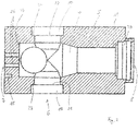
- figure 1 1 shows an essentially cuboid, flow-through measuring cell 1 with various means, described below, for accommodating measuring means for measuring chemical and/or physical properties of a fluid flowing through the measuring cell 1 .
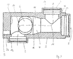
- FIG 3 It can be seen from schematic arrows (flow pattern) that the fluid enters a measuring chamber 4 through an inlet opening 2 for the inlet of the fluid.
- the measuring chamber 4 extends at an angle of 90° to the inlet opening 2 to the right, so that the fluid follows a curvature 10 and thus a curve represented schematically by an arrow.
- the fluid runs out of the measuring cell 1 through an outlet opening 3 .
- a bend 11 running in the opposite direction of the bend 10 is provided just before the outlet opening 3, so that the fluid again follows a curve of 90° represented by an arrow.
- Connection means 12, 13 are provided both at the inlet opening 2 and at the outlet opening 3, via which the measuring cell 1 can be connected to corresponding connections in the process flow as an inline measuring cell.
- a reduction 14, in particular conical, of the measuring chamber 4 in order to ensure that the flow of the fluid is as bubble-free or laminar as possible.
- Sealing means are provided on the connecting means 12, 13.
- adapters designed in particular as disposable adapters are advantageously provided for connecting various line connections, in particular pluggable.
- the adapters are in particular made of plastic and are packed at the same time as the measuring cell and made available as a measuring cell set. Such a measuring cell set offers the advantage that the inline installation can be carried out easily, quickly and safely on different line systems and thus the storage costs are also reduced.
- the measuring cell 1 consists essentially of a one-piece measuring cell body 5 made of plastic, in particular polyphenylene sulfone.
- plastic in particular polyphenylene sulfone.
- Inventive properties of the plastic are: precise machinability, high rigidity, gamma permeability and high Combustibility, ie at least 95% of the mass can be converted into the gas phase in the usual processes of household waste incineration.
- the measuring cell 1 can be coupled, in particular automatically, to the measuring means while avoiding a twisted or wrong connection.
- corresponding coupling means are provided on the line to be connected or on a receptacle for the measuring cell 1 on the line.
- the coding 15 or an additional coding comprises a parameter identifier for one or more parameters of the measuring cell 1.
- the parameter identifier can consist of a geometric configuration of the coding 15 or the additional coding, which is detected by the coupling means or separate detection means .
- Mechanical or electronic parameter identification is particularly advantageous.
- a transponder for identification with the aid of electromagnetic waves is particularly suitable as electronic parameter identification.
- the parameters are in particular the cell constant for the conductivity measurement and/or the optical path length of the respective measuring cell 1.
- the measuring chamber 4 has a measuring channel 16 , which is particularly tubular (preferably with a circular cross section) and extends over the entire length of the measuring cell 1 .
- a measuring channel 16 which is particularly tubular (preferably with a circular cross section) and extends over the entire length of the measuring cell 1 .
- the inlet opening 2 is arranged at an angle on the measuring channel 16
- the outlet opening 3 is arranged at an angle, namely in the opposite direction to the inlet opening 2.
- the axial direction of the inlet opening 2 and the axial direction of the outlet opening 3 are parallel to one another and run transversely or at an angle of 90° to the axial direction of the measuring channel 16.
- a radiation measuring area 6 for measuring the interaction of the fluid in the measuring cell 1 with electromagnetic radiation is located transversely or at an angle of 90° to the measuring channel and in particular also transversely or at an angle of 90° to the axial direction of the inlet opening 2 or the outlet opening 3.
- Electromagnetic radiation enters the measurement space 4 from a radiation source (not shown) through a radiation entry opening 19 and exits the measurement space 4 on the opposite side through a radiation exit opening 20, where it strikes a radiation measurement device.
- the beam path runs transversely or at an angle of 90° to the measuring channel 16 and the inlet opening 2 or the outlet opening 3.
- the axial direction of the aligned radiation inlet opening 19 and radiation inlet opening 20 coincides with the beam path.
- window receptacles 21, 22 are provided for receiving windows that are transparent to the electromagnetic radiation from the radiation source.
- the windows seal the measurement space 4 from the environment.
- the measuring cell 4 is designed such that no other components that interfere with the measurement are arranged in the beam path at least between the beam entry opening 19 and the beam exit opening 20, in particular between the windows.
- the optical path length i.e. the distance covered by the electromagnetic radiation when passing through the fluid, results from the contact of the window with stops 23, 24 of the window receptacle 21, 22.
- a conductivity measurement receptacle 7 for accommodating conductivity measurement means for measuring the conductivity of the fluid in the measurement cell 1 is provided at the first end 17 .
- the conductivity measurement recording 7 consists of four receiving openings 25 for current electrodes and two receiving openings 26 arranged between the receiving openings 25 for voltage electrodes.
- the current or voltage electrodes can be received in a sealed manner in the receiving openings 25 , 26 so that they terminate as flatly as possible with the first end 17 or protrude slightly into the measuring chamber 4 .
- the function of a conductivity sensor is in the DE19946315C2 described.
- the conductivity sensor according to DE19946315C2 in a receiving opening for receiving the housing 1 of the conductivity sensor according to FIG DE19946315C2 suitable and disclosed in combination with this as an invention.
- a mechanical coding 15 is provided which, with a corresponding pin, provides a recording device or coupling device for coupling the measuring cell 1 to the process line, with several, in particular asymmetrically, being attached to the measuring cell body 5
- the measuring cell body 5 distributed, coding 15 can be provided.
- the conductivity recording 7 is a temperature measuring area 9 in the form of a blind hole 27 reaching almost to the measuring chamber 4 .
- the blind hole 27 ends in the immediate vicinity of the first end 17 and in the area of the inlet opening 2.
- a thin partition 28 is provided, through which a measuring tip of a temperature sensor can be pierced, so that a reliable measurement and at the same time a good seal against the environment is made possible.
- a pH measuring receptacle 8 for accommodating pH value measuring means for measuring the pH value of the fluid in the measuring cell 1 is provided at the opposite second end 18 .
- the pH measurement receptacle 8 includes a receptacle opening 29 whose axial direction is aligned with the axial direction of the measurement channel 16 .
- a pH electrode that can be plugged into the receiving opening 29 can thus be plugged into the measuring chamber 4 in a sealing manner with respect to the surroundings of the measuring cell 1 and measures the pH value of the fluid flowing past.
- a tip of the pH electrode can advantageously be attached in the pH measuring receptacle 8 in such a way that it reaches at least below the outlet opening 3, in particular at least up to the middle of the outlet opening 3 in the measuring channel 16.
- the pH electrode can be fixed to the receiving opening 29 in a sealing manner.
- the measuring cell 1 can be aligned horizontally, as shown in the figures, so that the inlet opening 2 and/or the outlet opening 3 are aligned with the normal. This achieves optimal idling behavior.
- the installation space of the measuring cell 1 is further minimized if a beam path for measuring the electromagnetic radiation (radiation measuring area 6) runs horizontally.
Description
Die vorliegende Erfindung betrifft eine durchströmbare Messzelle zur Aufnahme von Messmitteln zur Messung von chemischen und/ oder physikalischen Eigenschaften eines die Messzelle durchströmenden Fluids gemäß Patentanspruch 1 sowie ein System gemäß Patentanspruch 11.The present invention relates to a flow-through measuring cell for accommodating measuring means for measuring chemical and/or physical properties of a fluid flowing through the measuring cell according to patent claim 1 and a system according to patent claim 11.
Insbesondere in der Biotechnologie und der Lebensmitteltechnologie sind durchströmbare Messzellen zur Steuerung und Validierung sowie Einhaltung von bestimmten Vorgaben nicht mehr wegzudenken. Anwendungsbeispiele sind die Chromatographie oder Ultrafiltration. Druckschrift
Besonders wichtig ist die Genauigkeit der Messzellen bei der Messung und das schnelle Ansprechen, weshalb solche Messzellen bisher aus qualitativ sehr hochwertigen Materialen hergestellt werden, beispielsweise Edelstahl. Ein wichtiger Aspekt besteht auch in der Reinigungsmöglichkeit, zumal die Messzelle häufig inline eingesetzt werden.The accuracy of the measuring cells during the measurement and the rapid response are particularly important, which is why such measuring cells have hitherto been made from very high-quality materials, such as stainless steel. Another important aspect is the possibility of cleaning, especially since the measuring cell is often used inline.
Da häufig, insbesondere in der Biotechnologie, sehr teuere Fluide untersucht werden, spielt auch das Volumen der Messzelle sowie entsprechende Toträume eine große Rolle. So besteht die Bestrebung, das Volumen des Messraums der Messzellen möglichst zu reduzieren, um beispielsweise eine Verschleppung bei einem Phasenwechsel und entsprechenden Materialverbrauch der teueren Medien möglichst gering zu halten. Entscheidend ist aber auch die Leerlaufeigenschaft der Messzelle, damit nach Ende des Messvorgangs keine Reste des Fluids mehr im Messraum verbleiben.Since very expensive fluids are often examined, especially in biotechnology, the volume of the measuring cell and the corresponding dead spaces also play a major role. So there is an effort to reduce the volume of the measuring space of the measuring cells as possible, for example To keep carryover at a phase change and corresponding material consumption of the expensive media as low as possible. The idling property of the measuring cell is also decisive, so that no residues of the fluid remain in the measuring chamber after the end of the measuring process.
Nicht nur die Reinigung spielt eine entscheidende Rolle, sondern auch die Möglichkeit einer Sterilisierung.Not only cleaning plays a decisive role, but also the possibility of sterilization.
Aufgabe der vorliegenden Erfindung ist es daher, eine nach den vorgenannten Vorgaben optimierte durchströmbare Messzelle anzugeben.It is therefore the object of the present invention to specify a flow-through measuring cell which is optimized according to the aforementioned specifications.
Diese Aufgabe wird mit den Merkmalen der Patentansprüche 1 und 11 gelöst.This object is achieved with the features of patent claims 1 and 11.
Vorteilhafte Weiterbildungen der Erfindung sind in den Unteransprüchen angegeben. Bei angegebenen Wertbereichen sollen auch innerhalb der genannten Grenzen liegende Werte als Grenzwerte offenbart gelten und in beliebiger Kombination beanspruchbar sein.Advantageous developments of the invention are specified in the dependent claims. In the case of specified value ranges, values lying within the specified limits should also apply as disclosed limit values and be claimable in any combination.
Der Erfindung liegt der Gedanke zugrunde, eine Messzelle anzugeben, in der bei geringst möglichem Volumen des Messraums sowohl eine Messung mit elektromagnetischer Strahlung als auch eine Leitfähigkeitsmessung und/oder eine pH-Messung und/oder eine Temperaturmessung durchführbar sind. Somit werden mindestens zwei Messungen in einem Messraum durch die erfindungsgemäße Ausgestaltung der durchströmbaren Messzelle ermöglicht, wovon eine eine Strahlungsmessung mit elektromagnetischer Strahlung ist. Insbesondere für die Strahlungsmessung ist zur Ermittlung der Wechselwirkung des Fluids mit der elektromagnetischen Strahlung ein gewisser Strahlengang erforderlich, sodass eine Reduzierung des Volumens kaum möglich ist. Die Erfindung besteht daher darin, mindestens eine weitere Messung im selben Messraum vorzusehen, um das bisher erforderliche Volumen für beide Messungen insgesamt sowie die Anzahl der zu verbauenden Messzellen zu reduzieren.The invention is based on the idea of specifying a measuring cell in which both a measurement with electromagnetic radiation and a conductivity measurement and/or a pH measurement and/or a temperature measurement can be carried out with the smallest possible volume of the measuring space. Thus, at least two measurements are made possible in a measuring room by the configuration of the flow-through measuring cell according to the invention, one of which is a radiation measurement with electromagnetic radiation. In order to determine the interaction of the fluid with the electromagnetic radiation, a certain beam path is required, in particular for the radiation measurement, so that the volume is reduced is hardly possible. The invention therefore consists in providing at least one further measurement in the same measuring space in order to reduce the volume previously required for both measurements overall and the number of measuring cells to be installed.
Gemäß einer vorteilhaften Ausführungsform der Erfindung ist vorgesehen, dass die Messzelle zumindest überwiegend, insbesondere zu mindestens 90%, vorzugsweise zu mindestens 95%, aus chemischen Elementen mit einer Ordnungszahl < 17 besteht. Somit ist die Messzelle so weit gammadurchlässig, dass eine vollständige und homogene Beaufschlagung des Messraums mit Gammastrahlen zur Desinfektion ermöglicht wird. Auf diese Weise wird die Herstellung und der Versand beziehungsweise Transport der erfindungsgemäßen Messzellen stark vereinfacht, da die Messzellen im verpackten Zustand mit Gammastrahlen beaufschlagt und entsprechend desinfiziert werden können. Somit kann eine Kontamination bei der Verpackung der Messzellen ausgeschlossen werden und die Verpackung entsprechend kostengünstiger durchgeführt werden.According to an advantageous embodiment of the invention, it is provided that the measuring cell consists at least predominantly, in particular at least 90%, preferably at least 95%, of chemical elements with an atomic number <17. The measuring cell is thus gamma-permeable to such an extent that the measuring room can be completely and homogeneously exposed to gamma rays for disinfection. This greatly simplifies the manufacture and shipping or transport of the measuring cells according to the invention, since the measuring cells can be exposed to gamma rays in the packaged state and disinfected accordingly. In this way, contamination during the packaging of the measuring cells can be ruled out and the packaging can be carried out more cost-effectively.
Indem die Messzelle einen Temperaturmessbereich zur Anordnung, insbesondere zum Anschluss, eines Temperatursensors aufweist, lässt sich zusätzlich und auf einfache Art und Weise eine Temperaturmessung in die Messzelle integrieren.Because the measuring cell has a temperature measuring area for arranging, in particular for connecting, a temperature sensor, a temperature measurement can also be easily integrated into the measuring cell.
Die Erfindung geht gemäß einer vorteilhaften Ausführungsform der Erfindung den zum Stand der Technik entgegengesetzten Weg, indem die Messzelle als Einwegmesszelle, insbesondere überwiegend, vorzugsweise im Wesentlichen vollständig, aus Kunststoff ausgebildet ist. Auf diese Weise ist es möglich, die für die Messung erforderlichen, hochwertigen und teueren Messmittel, für die besonders hohe Qualitätsanforderungen gelten, nach jedem Zyklus oder jeweils nach einer bestimmten Zeitdauer oder sogar bei jedem Wechsel eines Fluids, auszutauschen, während die teuren Messmittel weiterverwendet werden können.According to an advantageous embodiment of the invention, the invention takes the opposite route to the prior art, in that the measuring cell is designed as a disposable measuring cell, in particular predominantly, preferably essentially completely, made of plastic. In this way it is possible to exchange the high-quality and expensive measuring equipment required for the measurement, for which particularly high quality requirements apply, after each cycle or after a certain period of time or even with each change of a fluid, while the expensive measuring equipment continues to be used be able.
Besonders vorteilhaft ist es bei der vorliegenden Erfindung, dass gemäß einer Ausführungsform der Erfindung der, insbesondere überwiegend röhrenförmige, Messraum ein Volumen von weniger als 50ml, insbesondere weniger als 30ml, aufweist. Somit werden auf kleinstem Raum eine Vielzahl von Messungen an dem die Messzelle durchströmenden Fluid ermöglichst und der Materialverbrauch beziehungsweise die Verschleppung beim Phasenwechsel minimiert.It is particularly advantageous in the present invention that, according to one embodiment of the invention, the measuring chamber, which is in particular predominantly tubular, has a volume of less than 50 ml, in particular less than 30 ml. In this way, a large number of measurements on the fluid flowing through the measuring cell are made possible in the smallest of spaces, and material consumption or carryover during the phase change is minimized.
Da die Eintrittsöffnung und die Austrittsöffnung parallel versetzt zueinander verlaufen, lässt sich die Messzelle optimal in bestehende Systeme einbauen. Hierdurch wird außerdem die Montage der Messzelle erleichtert. Ein besonders gutes Strömungsprofil mit optimalem Leerlaufverhalten ist realisierbar, indem die Messzelle derart gestaltet ist, dass das Fluid von der Eintrittsöffnung bis zur Austrittsöffnung mindestens eine, insbesondere zwei, vorzugsweise genau zwei, Krümmungen durchläuft. Die Krümmungen haben insbesondere einen Krümmungswinkel von mindestens 45°, vorzugsweise etwa 90°. Auf diese Weise werden an der Messzelle mehrere Freiflächen zur Anbringung von Messmitteln geschaffen.Since the inlet opening and the outlet opening are offset parallel to one another, the measuring cell can be optimally installed in existing systems. This also facilitates the assembly of the measuring cell. A particularly good flow profile with optimum idling behavior can be achieved by designing the measuring cell in such a way that the fluid runs through at least one, in particular two, preferably exactly two, bends from the inlet opening to the outlet opening. In particular, the curvatures have an angle of curvature of at least 45°, preferably approximately 90°. In this way, several open spaces for attaching measuring equipment are created on the measuring cell.
Gemäß einer weiteren, vorteilhaften Ausführungsform der Erfindung ist vorgesehen, dass ein Strahlengang des Strahlungsmessbereichs quer zum Messraum und quer zur Eintrittsöffnung und/oder Austrittsöffnung verläuft. Auf diese Weise wird die Strahlungsmessung mit geringst möglichem Platzbedarf in die Messzelle oder an der Messzelle verwirklicht.According to a further advantageous embodiment of the invention, it is provided that a beam path of the radiation measurement area runs transversely to the measurement space and transversely to the entry opening and/or exit opening. In this way, the radiation measurement is realized with the smallest possible space requirement in the measuring cell or on the measuring cell.
Für die Leitfähigkeitsmessaufnahme und/oder die pH-Messaufnahme gilt gemäß einer weiteren vorteilhaften Ausführungsform der Erfindung, dass diese längs zur Messform und quer zur Eintrittsöffnung und/oder Austrittsöffnung angeordnet ist/sind. Hierdurch lässt sich unter optimaler Platzausnutzung eine Vollintegration der genannten Messmittel bei geringst möglichen Volumen erreichen.According to a further advantageous embodiment of the invention, the conductivity measurement recording and/or the pH measurement recording is/are arranged lengthwise to the measurement form and transversely to the inlet opening and/or outlet opening. This allows under optimal Use of space to achieve full integration of the measuring equipment mentioned with the lowest possible volume.
Das erfindungsgemäße System wird dadurch optimiert, indem gemäß einer vorteilhaften Ausführungsform die Messzelle als Einwegmesszelle für einen Messzyklus verwendbar ist beziehungsweise verwendet wird, während die Strahlungsmessmittel und/oder die Leitfähigkeitsmessmittel und/oder die pH-Wert-Messmittel für mehrere Messzyklen verwendbar sind beziehungsweise verwendet werden.The system according to the invention is optimized in that, according to an advantageous embodiment, the measuring cell can be used or is used as a disposable measuring cell for one measuring cycle, while the radiation measuring means and/or the conductivity measuring means and/or the pH measuring means can be used or are used for several measuring cycles .
Weitere Vorteile, Merkmale und Einzelheiten der Erfindung ergeben sich aus der nachfolgenden Beschreibung bevorzugter Ausführungsbeispiele sowie anhand der Zeichnungen. Diese zeigen in:
- Figur 1
- eine perspektivische Ansicht einer erfindungsgemäßen Messzelle mit Schnittebene A und Schnittebene B,
Figur 2- eine geschnittene Ansicht der Messzelle gemäß Schnittebene A aus
Figur 1 und Figur 3- eine geschnittene Ansicht der Messzelle der Schnittebene B aus
Figur 1 .
- figure 1
- a perspective view of a measuring cell according to the invention with section plane A and section plane B,
- figure 2
- shows a sectional view of the measuring cell according to section plane A
figure 1 and - figure 3
- a sectional view of the measuring cell of section plane B
figure 1 .
In den Figuren sind gleiche oder gleich wirkende Elemente oder Elemente mit der gleichen Funktion mit dem gleichen Bezugszeichen gekennzeichnet.In the figures, identical or identically acting elements or elements with the same function are identified by the same reference symbols.
In
Sowohl an der Eintrittsöffnung 2 als auch an der Austrittsöffnung 3 sind Anschlussmittel 12, 13 vorgesehen, über welche die Messzelle 1 an entsprechende Anschlüsse in den Prozesslauf als inline-Messzelle anschließbar ist. Im mittleren Bereich des Messraums 4 ist eine, insbesondere konusförmige, Reduzierung 14 des Messraums 4 vorgesehen, um eine möglichst blasenfreie oder laminare Strömung des Fluids zu gewährleisten. An den Anschlussmitteln 12, 13 sind Dichtungsmittel vorgesehen. Für die Anschlussmittel 12, 13 sind mit Vorteil, insbesondere als Einwegadapter ausgebildete, Adapter zum, insbesondere steckbaren, Anschluss verschiedener Leitungsanschlüsse vorgesehen. Die Adapter sind insbesondere aus Kunststoff gebildet und werden gleichzeitig mit der Messzelle verpackt und als Messzellenset zur Verfügung gestellt. Ein solches Messzellenset bietet den Vorteil, dass der inline-Einbau problemlos, schnell und sicher an verschiedene Leitungssysteme erfolgen kann und somit auch die Lagerhaltungskosten reduziert werden.Connection means 12, 13 are provided both at the
Die Messzelle 1 besteht im Wesentlichen aus einem einteiligen Messzellenkörper 5 aus Kunststoff, insbesondere Polyphenylensulfon. Erfindungsgemäße Eigenschaften des Kunststoffs sind: präzise Bearbeitbarkeit, hohe Steifheit, Gammadurchlässigkeit und hohe Verbrennbarkeit, d.h. zu mindestens 95% der Masse in der Zeit üblichen Prozessen der Hausmüllverbrennung die Gasphase überführbar.The measuring cell 1 consists essentially of a one-piece measuring
Durch Vorsehen einer Kodierung 15 ist die Messzelle 1, insbesondere automatisch, mit den Messmitteln unter Vermeidung eines verdrehten oder falschen Anschlusses koppelbar. Hierzu sind an der anzuschließenden Leitung oder einer Aufnahme für die Messzelle 1 an der Leitung korrespondierende Koppelmittel vorgesehen.By providing a
Die Kodierung 15 oder eine zusätzliche Kodierung umfasst in einer vorteilhaften Ausführungsform der Erfindung eine Parameterkennung für einen oder mehrere Parameter der Messzelle 1. Die Parameterkennung kann aus einer geometrischen Ausbildung der Kodierung 15 oder der zusätzlichen Kodierung bestehen, die von den Koppelmittel oder separaten Erfassungsmitteln erfasst werden. Besonders vorteilhaft ist eine mechanische oder elektronische Parameterkennung. Als elektronische Parameterkennung kommt insbesondere ein Transponder für die Identifizierung mit Hilfe elektromagnetischer Wellen in Frage.In an advantageous embodiment of the invention, the
Die Parameter sind insbesondere die Zellkonstante für die Leitfähigkeitsmessung und/oder die optische Pfadlänge der jeweiligen Messzelle 1.The parameters are in particular the cell constant for the conductivity measurement and/or the optical path length of the respective measuring cell 1.
Der Messraum 4 weist einen, insbesondere röhrenförmigen (vorzugsweise mit kreisförmigen Querschnitt), Messkanal 16 auf, der sich quasi über die gesamte Länge der Messzelle 1 erstreckt. An einem ersten Ende 17 des Messkanals 16 ist die Eintrittsöffnung 2 am Messkanal 16 angewinkelt angeordnet, während an einem zweiten Ende 18 des Messkanals 16 die Austrittsöffnung 3 angewinkelt angeordnet ist, und zwar in entgegengesetzte Richtung zur Eintrittsöffnung 2.The measuring
Die Axialrichtung der Eintrittsöffnung 2 und die Axialrichtung der Austrittöffnung 3 sind parallel zueinander und verlaufen quer beziehungsweise unter einem Winkel von 90° zur Axialrichtung des Messkanals 16.The axial direction of the
Quer beziehungsweise unter einem Winkel von 90° zum Messkanal sowie insbesondere auch quer beziehungsweise unter einem Winkel von 90° zu der Axialrichtung der Eintrittsöffnung 2 beziehungsweise der Austrittsöffnung 3 liegt ein Strahlenmessbereich 6 zur Messung der Wechselwirkung des Fluids in der Messzelle 1 mit einer elektromagnetischen Strahlung. Elektromagnetische Strahlung tritt von einer nicht dargstellten Strahlungsquelle durch eine Strahlungseintrittsöffnung 19 in den Messraum 4 ein und auf der gegenüberliegenden Seite durch eine Strahlungsaustrittsöffnung 20 wieder aus dem Messraum 4 heraus, wo sie auf eine Strahlungsmesseinrichtung trifft. Der Strahlengang verläuft quer beziehungsweise in einem Winkel von 90° zu dem Messkanal 16 und der Eintrittsöffnung 2 beziehungsweise der Austrittsöffnung 3. Die Axialrichtung der zueinander fluchtenden Strahlungseintrittsöffnung 19 und Strahlungseintrittsöffnung 20 deckt sich mit dem Strahlengang.A
In der Strahleneintrittsöffnung 19 und in der Strahlenaustrittöffnung 20 sind jeweils Fensteraufnahmen 21, 22 zur Aufnahme von für die elektromagnetische Strahlung der Strahlungsquelle transparenten Fenstern vorgesehen. Die Fenster dichten den Messraum 4 gegenüber der Umgebung ab.In the
Die Messzelle 4 ist erfindungsgemäß so ausgebildet, dass im Strahlengang zumindest zwischen zwischen der Strahleneintrittsöffnung 19 und der Strahlenaustrittsöffnung 20, insbesondere zwischen den Fenstern, keine die Messung störenden weiteren Bauteile angeordnet sind.According to the invention, the measuring
Die optische Pfadlänge, also die Strecke, die die elektromagnetische Strahlung beim Durchtritt durch das Fluid zurücklegt, ergibt sich durch die Anlage der Fenster an Anschlägen 23, 24 der Fensteraufnahme 21, 22.The optical path length, i.e. the distance covered by the electromagnetic radiation when passing through the fluid, results from the contact of the window with
An dem ersten Ende 17 ist eine Leitfähigkeitmessaufnahme 7 zur Aufnahme von Leitfähigkeitsmessmitteln zur Messung der Leitfähigkeit des Fluids in der Messzelle 1 vorgesehen. Die Leitfähigkeitsmessaufnahme 7 besteht im vorliegenden Fall aus vier Aufnahmeöffnungen 25 für Stromelektroden und zwei zwischen den Aufnahmeöffnungen 25 angeordneten Aufnahmeöffnungen 26 für Spannungselektroden. In den Aufnahmeöffnungen 25, 26 sind die Strom- beziehungsweise Spannungselektroden dichtend aufnehmbar, sodass diese möglichst plan mit dem ersten Ende 17 abschließen oder leicht in den Messraum 4 hineinragen. Die Funktion eines Leitfähigkeitssensors ist in der
Neben (vorzugsweise an der gleichen Seite der Messzelle 1) der Leitfähigkeitsaufnahme 7 ist eine mechanische Kodierung 15 vorgesehen, die mit einem entsprechenden Stift eine Aufnahmeeinrichtung beziehungsweise Koppeleinrichtung zur Kopplung der Messzelle 1 an der Prozessleitung vorgesehen, wobei an dem Messzellenkörper 5 mehrere, insbesondere asymmetrisch an dem Messzellenkörper 5 verteilte, Kodierungen 15 vorgesehen sein können.Next to (preferably on the same side of the measuring cell 1) the conductivity recording 7, a
Ebenfalls neben (vorzugsweise an der gleichen Seite der Messzelle 1) der Leitfähigkeitsaufnahme 7 ist ein Temperaturmessbereich 9 in Form eines fast bis zum Messraum 4 reichenden Sacklochs 27 vorgesehen. Das Sackloch 27 endet in unmittelbarer Nähe des ersten Endes 17 und im Bereich der Eintrittsöffnung 2. Zwischen dem Sackloch 27 und dem erstem Ende 17 ist eine dünne Trennwand 28 vorgesehen, durch die eine Messspitze eines Temperaturfühlers hindurch gestochen werden kann, sodass eine verlässliche Messung und gleichzeitig eine gute Abdichtung gegenüber der Umgebung ermöglicht wird.Also next to (preferably on the same side of the measuring cell 1) the conductivity recording 7 is a
Am gegenüberliegenden zweiten Ende 18 ist eine pH-Messaufnahme 8 zur Aufnahme von pH-Wert-Messmitteln zur Messung des pH-Werts des Fluids in der Messzelle 1 vorgesehen. Die pH-Messaufnahme 8 umfasst eine Aufnahmeöffnung 29, deren Axialrichtung mit der Axialrichtung des Messkanals 16 fluchtend ausgerichtet ist. Ein in die Aufnahmeöffnung 29 steckbare pH-Elektrode ist somit dichtend gegenüber der Umgebung der Messzelle 1 in den Messraum 4 steckbar und misst den pH-Wert des vorbeiströmenden Fluids.A
Eine Spitze der pH-Elektrode ist bei dem erfindungsgemäßen System mit Vorteil derart in der pH-Messaufnahme 8 anbringbar, dass diese mindestens bis unter der Austrittsöffnung 3, insbesondere mindestens bis zur Mitte der Austrittsöffnung 3 in dem Messkanal 16 reicht. Die pH-Elektrode ist an der Aufnahmeöffnung 29 dichtend fixierbar.In the system according to the invention, a tip of the pH electrode can advantageously be attached in the
Die Messzelle 1 ist erfindungsgemäß so horizontal ausrichtbar, wie es in den Figuren dargestellt ist, so dass die Eintrittsöffnung 2 und/oder die Austrittsöffnung 3 mit der Normalen fluchten. Hierdurch wird ein optimales Leerlaufverhalten erreicht.According to the invention, the measuring cell 1 can be aligned horizontally, as shown in the figures, so that the
Der Bauraum der Messzelle 1 wird weiter minimiert, wenn dabei ein Strahlengang für die Messung der elektromagnetischen Strahlung (Strahlungsmessbereich 6) horizontal verläuft.The installation space of the measuring cell 1 is further minimized if a beam path for measuring the electromagnetic radiation (radiation measuring area 6) runs horizontally.
Noch weiter optimierbar ist dies, indem die pH-Messaufnahme im Wesentlichen horizontal, insbesondere maximal mit einem Winkel von 20° zur Horizontalen, verläuft.This can be optimized even further if the pH measurement recording runs essentially horizontally, in particular at a maximum angle of 20° to the horizontal.
- 1 Messzelle1 measuring cell
- 2 Eintrittsöffnung2 entry port
- 3 Austrittsöffnung3 exit port
- 4 Messraum4 measuring room
- 5 Messzellenkörper5 measuring cell body
- 6 Strahlungsmessbereich6 radiation measurement area
- 7 Leitfähigkeitsmessaufnahme7 conductivity measurement recording
- 8 pH-Messaufnahme8 pH measurement recording
- 9 Temperaturmessbereich9 temperature measurement range
- 10 Krümmung10 curvature
- 11 Krümmung11 curvature
- 12 Anschlussmittel12 connection means
- 13 Anschlussmittel13 connection means
- 14 Reduzierung14 reduction
- 15 Kodierung15 encoding
- 16 Messkanal16 measuring channel
- 17 Erstes Ende17 First End
- 18 Zweites Ende18 Second ending
- 19 Strahlungseintrittsöffnung19 radiation entrance opening
- 20 Strahlungsaustrittsöffnung20 radiation exit opening
- 21 Fensteraufnahme21 window shot
- 22 Fensteraufnahme22 window shot
- 23 Anschläge23 stops
- 24 Anschläge24 stops
- 25 Aufnahmeöffnungen25 intake openings
- 26 Aufnahmeöffnungen26 recording holes
- 27 Sackloch27 blind hole
- 28 Trennwand28 partition
- 29 Aufnahmeöffnung29 receiving opening
Claims (12)
- Flow-through measurement cell for receiving measurement means for measuring chemical and/or physical properties of a fluid flowing through the measurement cell (1):- an inlet opening (2) for the inlet of the fluid,- an outlet opening (3) for the outlet of the fluid,- a, in particular sole, measurement chamber (4) arranged between the inlet opening (2) and the outlet opening (3),- a radiation measurement area (6) for measuring the interaction of the fluid in the measurement cell (1) with an electromagnetic radiation from outside the measurement cell (1) and- a conductivity measurement receptacle (7) for receiving conductivity measurement means for measuring the conductivity of the fluid in the measurement cell (1) and/or a pH measurement receptacle (8) for receiving pH-value measurement means for measuring the pH value of the fluid in the measurement cell (1),characterized in that the inlet opening (2) and the outlet opening (3) are offset in relation to each other in a parallel direction.
- The measurement cell according to claim 1, wherein at least most, in particular at least 90%, preferably at least 95%, of the measurement cell (1) is composed of chemical elements with an atomic number <17.
- The measurement cell according to one of the preceding claims, wherein the measurement cell (1) in the form of a disposable measurement cell is composed in particular mostly, preferably essentially entirely, of plastic.
- The measurement cell according to one of the preceding claims, wherein the measurement cell has a temperature measurement area (9) for arranging, in particular connecting, a temperature sensor.
- The measurement cell according to one of the preceding claims, wherein the, in particular predominantly tubular, measurement chamber (4) has a volume of less than 50 ml, in particular less than 30 ml.
- The measurement cell according to one of the preceding claims, wherein the measurement cell (1) is designed such that from the inlet opening (2) to the outlet opening (3) the fluid passes through at least one, in particular two, preferably exactly two, bends (10, 11), in particular with an angle of curvature of at least 45°, preferably approximately 90°.
- The measurement cell according to one of the preceding claims, wherein a radiation path of the radiation measurement area (6) runs transversely to the measurement chamber (4) and transversely to the inlet opening (2) and/or outlet opening (3).
- The measurement cell according to one of the preceding claims, wherein the conductivity receptacle (7) and/or the pH measurement receptable (8) is/are arranged longitudinally to the measurement chamber (4) and transversely to the inlet opening (2) and/or the outlet opening (3).
- The measurement cell according to one of the preceding claims, wherein the electromagnetic radiation enters the measurement chamber (4) through a radiation inlet opening (19) and exits the measurement chamber (4) on the opposite side through a radiation outlet opening (20).
- The measurement cell according to claim 10, wherein window receptacles (21, 22) for receiving windows transparent to the electromagnetic radiation of the radiation source are respectively provided in the radiation inlet opening (19) and in the radiation outlet opening (20).
- System comprising a measurement cell according to one of the preceding claims and- a radiation means attachable to the measurement cell for generating the electromagnetic radiation for measuring the interaction of the fluid in the measurement cell (1) with an electromagnetic radiation from outside the measurement cell (1) and- the conductivity measurement means attachable to the conductivity receptacle (7) and/or- the pH-value measurement means (8) attachable to the pH measurement receptacle.
- The system according to claim 11, comprising a radiation measurement device attachable to an opposite side of the measurement cell relative to the radiation means.
Applications Claiming Priority (3)
| Application Number | Priority Date | Filing Date | Title |
|---|---|---|---|
| DE102011013001.2A DE102011013001B4 (en) | 2011-03-04 | 2011-03-04 | Flow-through measuring cell for holding measuring instruments |
| EP12707727.9A EP2681531B1 (en) | 2011-03-04 | 2012-02-27 | Permeable measuring cell for receiving measuring means |
| PCT/EP2012/053254 WO2012119876A1 (en) | 2011-03-04 | 2012-02-27 | Permeable measuring cell for receiving measuring means |
Related Parent Applications (2)
| Application Number | Title | Priority Date | Filing Date |
|---|---|---|---|
| EP12707727.9A Division EP2681531B1 (en) | 2011-03-04 | 2012-02-27 | Permeable measuring cell for receiving measuring means |
| EP12707727.9A Division-Into EP2681531B1 (en) | 2011-03-04 | 2012-02-27 | Permeable measuring cell for receiving measuring means |
Publications (2)
| Publication Number | Publication Date |
|---|---|
| EP3832291A1 EP3832291A1 (en) | 2021-06-09 |
| EP3832291B1 true EP3832291B1 (en) | 2022-06-15 |
Family
ID=45811477
Family Applications (2)
| Application Number | Title | Priority Date | Filing Date |
|---|---|---|---|
| EP21154581.9A Active EP3832291B1 (en) | 2011-03-04 | 2012-02-27 | Permeable measuring cell for receiving measuring means |
| EP12707727.9A Active EP2681531B1 (en) | 2011-03-04 | 2012-02-27 | Permeable measuring cell for receiving measuring means |
Family Applications After (1)
| Application Number | Title | Priority Date | Filing Date |
|---|---|---|---|
| EP12707727.9A Active EP2681531B1 (en) | 2011-03-04 | 2012-02-27 | Permeable measuring cell for receiving measuring means |
Country Status (6)
| Country | Link |
|---|---|
| US (1) | US9423367B2 (en) |
| EP (2) | EP3832291B1 (en) |
| DE (1) | DE102011013001B4 (en) |
| DK (2) | DK3832291T3 (en) |
| ES (2) | ES2872390T3 (en) |
| WO (1) | WO2012119876A1 (en) |
Families Citing this family (5)
| Publication number | Priority date | Publication date | Assignee | Title |
|---|---|---|---|---|
| DE102013100158A1 (en) * | 2012-12-21 | 2014-07-10 | Endress + Hauser Gmbh + Co. Kg | Device for determining or monitoring a process variable of a medium in a pipeline |
| US11079350B2 (en) * | 2016-03-25 | 2021-08-03 | Parker-Hannifin Corporation | Solid state pH sensing continuous flow system |
| WO2021216393A1 (en) * | 2020-04-20 | 2021-10-28 | The Government Of The United States Of America, As Represented By The Secretary Of The Navy | Electrochemical flow cell framework for evaluating electroactive biofilms |
| EP4019954A1 (en) * | 2020-12-22 | 2022-06-29 | optek-Danulat GmbH | Measurement cell with anti-rotation feature |
| US11692990B1 (en) * | 2022-01-25 | 2023-07-04 | Saudi Arabian Oil Company | PH monitoring in porous media during waterflooding experiments |
Citations (5)
| Publication number | Priority date | Publication date | Assignee | Title |
|---|---|---|---|---|
| US4462962A (en) | 1982-07-19 | 1984-07-31 | Toyo Soda Manufacturing Co., Ltd. | Liquid chromatographic flow cell |
| DE19532382A1 (en) | 1995-09-01 | 1997-03-06 | Max Planck Gesellschaft | Analyser for chemical or physical changes in fluids |
| EP1418419A2 (en) | 1993-01-12 | 2004-05-12 | Applera Corporation | A high efficiency fluorescence flow cell |
| DE69731000T2 (en) | 1997-02-27 | 2005-10-06 | Terumo Cardiovascular Systems Corp. | DEVICE FOR MEASURING BLOOD PARAMETERS |
| WO2010126692A1 (en) | 2009-04-27 | 2010-11-04 | Endress+Hauser Conducta Inc. | Multi-port inline flow cell for use in monitoring multiple parameters in a sanitary process line |
Family Cites Families (12)
| Publication number | Priority date | Publication date | Assignee | Title |
|---|---|---|---|---|
| EP0089157A1 (en) | 1982-03-15 | 1983-09-21 | J & W SCIENTIFIC, INC. | Optical detector cell |
| DE9315488U1 (en) * | 1993-10-13 | 1994-02-10 | Fastenroth Gerd | Liquid flow measuring cell |
| GB2282880B (en) | 1993-10-18 | 1997-07-23 | Welsh Water Enterprises Ltd | Apparatus for measuring characteristics of a liquid |
| US5923433A (en) * | 1997-10-28 | 1999-07-13 | Honeywell Inc. | Overmolded flowthrough turbidity sensor |
| DE29924000U1 (en) | 1999-09-28 | 2002-01-03 | Pharmaserv Marburg Gmbh & Co K | conductivity sensor |
| US6663995B2 (en) * | 2002-04-30 | 2003-12-16 | General Motors Corporation | End plates for a fuel cell stack structure |
| US7224449B2 (en) * | 2005-10-21 | 2007-05-29 | Agilent Technologies, Inc. | Optical fluidic system with a capillary having a drilled through hole |
| JP4184423B2 (en) * | 2005-10-28 | 2008-11-19 | 松下電器産業株式会社 | Measuring device, measuring apparatus and measuring method |
| US7403280B2 (en) * | 2005-11-03 | 2008-07-22 | Agilent Technologies, Inc. | Fiber coupling into bent capillary |
| US7857506B2 (en) * | 2005-12-05 | 2010-12-28 | Sencal Llc | Disposable, pre-calibrated, pre-validated sensors for use in bio-processing applications |
| GB0703175D0 (en) | 2007-02-20 | 2007-03-28 | Ge Healthcare Bio Sciences Ab | Polymeric device suitable for ultraviolet detection |
| US20100317093A1 (en) * | 2009-06-10 | 2010-12-16 | Cynvenio Biosystems, Inc. | Flexible pouch and cartridge with fluidic circuits |
-
2011
- 2011-03-04 DE DE102011013001.2A patent/DE102011013001B4/en not_active Revoked
-
2012
- 2012-02-27 ES ES12707727T patent/ES2872390T3/en active Active
- 2012-02-27 DK DK21154581.9T patent/DK3832291T3/en active
- 2012-02-27 ES ES21154581T patent/ES2925572T3/en active Active
- 2012-02-27 EP EP21154581.9A patent/EP3832291B1/en active Active
- 2012-02-27 US US14/002,808 patent/US9423367B2/en active Active
- 2012-02-27 EP EP12707727.9A patent/EP2681531B1/en active Active
- 2012-02-27 WO PCT/EP2012/053254 patent/WO2012119876A1/en active Application Filing
- 2012-02-27 DK DK12707727.9T patent/DK2681531T3/en active
Patent Citations (5)
| Publication number | Priority date | Publication date | Assignee | Title |
|---|---|---|---|---|
| US4462962A (en) | 1982-07-19 | 1984-07-31 | Toyo Soda Manufacturing Co., Ltd. | Liquid chromatographic flow cell |
| EP1418419A2 (en) | 1993-01-12 | 2004-05-12 | Applera Corporation | A high efficiency fluorescence flow cell |
| DE19532382A1 (en) | 1995-09-01 | 1997-03-06 | Max Planck Gesellschaft | Analyser for chemical or physical changes in fluids |
| DE69731000T2 (en) | 1997-02-27 | 2005-10-06 | Terumo Cardiovascular Systems Corp. | DEVICE FOR MEASURING BLOOD PARAMETERS |
| WO2010126692A1 (en) | 2009-04-27 | 2010-11-04 | Endress+Hauser Conducta Inc. | Multi-port inline flow cell for use in monitoring multiple parameters in a sanitary process line |
Also Published As
| Publication number | Publication date |
|---|---|
| DE102011013001B4 (en) | 2016-05-25 |
| ES2925572T3 (en) | 2022-10-18 |
| DE102011013001A1 (en) | 2012-09-06 |
| EP3832291A1 (en) | 2021-06-09 |
| DK3832291T3 (en) | 2022-08-15 |
| EP2681531A1 (en) | 2014-01-08 |
| EP2681531B1 (en) | 2021-03-17 |
| DK2681531T3 (en) | 2021-06-07 |
| WO2012119876A1 (en) | 2012-09-13 |
| US20140004002A1 (en) | 2014-01-02 |
| US9423367B2 (en) | 2016-08-23 |
| ES2872390T3 (en) | 2021-11-02 |
Similar Documents
| Publication | Publication Date | Title |
|---|---|---|
| DE112010001778B4 (en) | Multi-port in-line flow cell for use in monitoring multiple parameters in a hygienic process line | |
| EP3832291B1 (en) | Permeable measuring cell for receiving measuring means | |
| EP2864758B1 (en) | Sensor and methods for measuring particles in media | |
| DE112011103757T5 (en) | UV miniature sensor with disposable flow cell | |
| DE4443016A1 (en) | Spectral analyser of gas concentration | |
| EP1866634B1 (en) | Wastewater analysis sensor cartridge | |
| DE4415889A1 (en) | Transducer for measuring liquid flows with ultrasound | |
| EP2267416A1 (en) | Flow rate measuring apparatus for fluid media with flow rectifier | |
| EP3169991B1 (en) | Sensor for detecting a liquid in a fluid channel | |
| DE102011084171B4 (en) | Device for non-contact flow measurement of fluids in flexible hoses | |
| EP1269152A1 (en) | Optical device for simultaneous multiple measurement using polarimetry and spectrometry and method for regulating/monitoring physical-chemical and biotechnical processes using said device | |
| DE102007034158B9 (en) | Device for the indirect measurement of the exhaustion of the filter medium of a filter | |
| DE102008033701A1 (en) | Flow rate measuring device for pipeline, has connecting elements forming mechanical identification unit for measuring tube and ultrasonic measuring device, and ultrasonic converters fixedly arranged in housing at predetermined distance | |
| EP3942013A1 (en) | Container for storing, mixing and/or cultivating a medium | |
| DE102017116269A1 (en) | Modular sensor arrangement | |
| EP0952448A1 (en) | Sensor holder arrangement for measuring fluids in processing | |
| DE102019109787A1 (en) | Hygienic pipe adapter | |
| EP2270435A2 (en) | Optical sensor finger | |
| EP2317288B1 (en) | Throughflow volume measuring device with mirror at the measuring tube end | |
| DE102006023223B3 (en) | Apparatus for analyzing a liquid sample with a multi-lumen capillary | |
| DE202009017275U1 (en) | Magnetic-inductive flowmeter | |
| AT510630B1 (en) | SPECTROMETER | |
| DE19810400A1 (en) | Through-flow cell, e.g. for on-line measurement of parameters of ground water samples always guarantees bubble-free measurement | |
| DE102008006035B3 (en) | Micro-technical component for testing characteristics of fluid sample i.e. serum, in e.g. biological field, has protective layer arranged at substrate or cover such that functional element is shielded against incident radiation | |
| EP3559612B1 (en) | Housing for a flow measuring device, and a flow measuring device having such a housing |
Legal Events
| Date | Code | Title | Description |
|---|---|---|---|
| PUAI | Public reference made under article 153(3) epc to a published international application that has entered the european phase |
Free format text: ORIGINAL CODE: 0009012 |
|
| STAA | Information on the status of an ep patent application or granted ep patent |
Free format text: STATUS: THE APPLICATION HAS BEEN PUBLISHED |
|
| AC | Divisional application: reference to earlier application |
Ref document number: 2681531 Country of ref document: EP Kind code of ref document: P |
|
| AK | Designated contracting states |
Kind code of ref document: A1 Designated state(s): AL AT BE BG CH CY CZ DE DK EE ES FI FR GB GR HR HU IE IS IT LI LT LU LV MC MK MT NL NO PL PT RO RS SE SI SK SM TR |
|
| STAA | Information on the status of an ep patent application or granted ep patent |
Free format text: STATUS: REQUEST FOR EXAMINATION WAS MADE |
|
| 17P | Request for examination filed |
Effective date: 20211109 |
|
| RBV | Designated contracting states (corrected) |
Designated state(s): AL AT BE BG CH CY CZ DE DK EE ES FI FR GB GR HR HU IE IS IT LI LT LU LV MC MK MT NL NO PL PT RO RS SE SI SK SM TR |
|
| GRAP | Despatch of communication of intention to grant a patent |
Free format text: ORIGINAL CODE: EPIDOSNIGR1 |
|
| STAA | Information on the status of an ep patent application or granted ep patent |
Free format text: STATUS: GRANT OF PATENT IS INTENDED |
|
| INTG | Intention to grant announced |
Effective date: 20220324 |
|
| GRAS | Grant fee paid |
Free format text: ORIGINAL CODE: EPIDOSNIGR3 |
|
| GRAA | (expected) grant |
Free format text: ORIGINAL CODE: 0009210 |
|
| STAA | Information on the status of an ep patent application or granted ep patent |
Free format text: STATUS: THE PATENT HAS BEEN GRANTED |
|
| AC | Divisional application: reference to earlier application |
Ref document number: 2681531 Country of ref document: EP Kind code of ref document: P |
|
| AK | Designated contracting states |
Kind code of ref document: B1 Designated state(s): AL AT BE BG CH CY CZ DE DK EE ES FI FR GB GR HR HU IE IS IT LI LT LU LV MC MK MT NL NO PL PT RO RS SE SI SK SM TR |
|
| REG | Reference to a national code |
Ref country code: CH Ref legal event code: EP Ref country code: GB Ref legal event code: FG4D Free format text: NOT ENGLISH |
|
| REG | Reference to a national code |
Ref country code: IE Ref legal event code: FG4D Free format text: LANGUAGE OF EP DOCUMENT: GERMAN |
|
| REG | Reference to a national code |
Ref country code: DE Ref legal event code: R096 Ref document number: 502012017061 Country of ref document: DE |
|
| REG | Reference to a national code |
Ref country code: AT Ref legal event code: REF Ref document number: 1498665 Country of ref document: AT Kind code of ref document: T Effective date: 20220715 |
|
| REG | Reference to a national code |
Ref country code: DK Ref legal event code: T3 Effective date: 20220808 |
|
| REG | Reference to a national code |
Ref country code: NL Ref legal event code: FP |
|
| REG | Reference to a national code |
Ref country code: SE Ref legal event code: TRGR |
|
| REG | Reference to a national code |
Ref country code: LT Ref legal event code: MG9D |
|
| REG | Reference to a national code |
Ref country code: ES Ref legal event code: FG2A Ref document number: 2925572 Country of ref document: ES Kind code of ref document: T3 Effective date: 20221018 |
|
| PG25 | Lapsed in a contracting state [announced via postgrant information from national office to epo] |
Ref country code: NO Free format text: LAPSE BECAUSE OF FAILURE TO SUBMIT A TRANSLATION OF THE DESCRIPTION OR TO PAY THE FEE WITHIN THE PRESCRIBED TIME-LIMIT Effective date: 20220915 Ref country code: LT Free format text: LAPSE BECAUSE OF FAILURE TO SUBMIT A TRANSLATION OF THE DESCRIPTION OR TO PAY THE FEE WITHIN THE PRESCRIBED TIME-LIMIT Effective date: 20220615 Ref country code: HR Free format text: LAPSE BECAUSE OF FAILURE TO SUBMIT A TRANSLATION OF THE DESCRIPTION OR TO PAY THE FEE WITHIN THE PRESCRIBED TIME-LIMIT Effective date: 20220615 Ref country code: GR Free format text: LAPSE BECAUSE OF FAILURE TO SUBMIT A TRANSLATION OF THE DESCRIPTION OR TO PAY THE FEE WITHIN THE PRESCRIBED TIME-LIMIT Effective date: 20220916 Ref country code: FI Free format text: LAPSE BECAUSE OF FAILURE TO SUBMIT A TRANSLATION OF THE DESCRIPTION OR TO PAY THE FEE WITHIN THE PRESCRIBED TIME-LIMIT Effective date: 20220615 Ref country code: BG Free format text: LAPSE BECAUSE OF FAILURE TO SUBMIT A TRANSLATION OF THE DESCRIPTION OR TO PAY THE FEE WITHIN THE PRESCRIBED TIME-LIMIT Effective date: 20220915 |
|
| PG25 | Lapsed in a contracting state [announced via postgrant information from national office to epo] |
Ref country code: RS Free format text: LAPSE BECAUSE OF FAILURE TO SUBMIT A TRANSLATION OF THE DESCRIPTION OR TO PAY THE FEE WITHIN THE PRESCRIBED TIME-LIMIT Effective date: 20220615 Ref country code: LV Free format text: LAPSE BECAUSE OF FAILURE TO SUBMIT A TRANSLATION OF THE DESCRIPTION OR TO PAY THE FEE WITHIN THE PRESCRIBED TIME-LIMIT Effective date: 20220615 |
|
| PG25 | Lapsed in a contracting state [announced via postgrant information from national office to epo] |
Ref country code: SM Free format text: LAPSE BECAUSE OF FAILURE TO SUBMIT A TRANSLATION OF THE DESCRIPTION OR TO PAY THE FEE WITHIN THE PRESCRIBED TIME-LIMIT Effective date: 20220615 Ref country code: SK Free format text: LAPSE BECAUSE OF FAILURE TO SUBMIT A TRANSLATION OF THE DESCRIPTION OR TO PAY THE FEE WITHIN THE PRESCRIBED TIME-LIMIT Effective date: 20220615 Ref country code: RO Free format text: LAPSE BECAUSE OF FAILURE TO SUBMIT A TRANSLATION OF THE DESCRIPTION OR TO PAY THE FEE WITHIN THE PRESCRIBED TIME-LIMIT Effective date: 20220615 Ref country code: PT Free format text: LAPSE BECAUSE OF FAILURE TO SUBMIT A TRANSLATION OF THE DESCRIPTION OR TO PAY THE FEE WITHIN THE PRESCRIBED TIME-LIMIT Effective date: 20221017 Ref country code: EE Free format text: LAPSE BECAUSE OF FAILURE TO SUBMIT A TRANSLATION OF THE DESCRIPTION OR TO PAY THE FEE WITHIN THE PRESCRIBED TIME-LIMIT Effective date: 20220615 Ref country code: CZ Free format text: LAPSE BECAUSE OF FAILURE TO SUBMIT A TRANSLATION OF THE DESCRIPTION OR TO PAY THE FEE WITHIN THE PRESCRIBED TIME-LIMIT Effective date: 20220615 |
|
| PG25 | Lapsed in a contracting state [announced via postgrant information from national office to epo] |
Ref country code: PL Free format text: LAPSE BECAUSE OF FAILURE TO SUBMIT A TRANSLATION OF THE DESCRIPTION OR TO PAY THE FEE WITHIN THE PRESCRIBED TIME-LIMIT Effective date: 20220615 Ref country code: IS Free format text: LAPSE BECAUSE OF FAILURE TO SUBMIT A TRANSLATION OF THE DESCRIPTION OR TO PAY THE FEE WITHIN THE PRESCRIBED TIME-LIMIT Effective date: 20221015 |
|
| REG | Reference to a national code |
Ref country code: DE Ref legal event code: R026 Ref document number: 502012017061 Country of ref document: DE |
|
| PLBI | Opposition filed |
Free format text: ORIGINAL CODE: 0009260 |
|
| PLAB | Opposition data, opponent's data or that of the opponent's representative modified |
Free format text: ORIGINAL CODE: 0009299OPPO |
|
| PLAX | Notice of opposition and request to file observation + time limit sent |
Free format text: ORIGINAL CODE: EPIDOSNOBS2 |
|
| PG25 | Lapsed in a contracting state [announced via postgrant information from national office to epo] |
Ref country code: AL Free format text: LAPSE BECAUSE OF FAILURE TO SUBMIT A TRANSLATION OF THE DESCRIPTION OR TO PAY THE FEE WITHIN THE PRESCRIBED TIME-LIMIT Effective date: 20220615 |
|
| PGFP | Annual fee paid to national office [announced via postgrant information from national office to epo] |
Ref country code: NL Payment date: 20230220 Year of fee payment: 12 |
|
| 26 | Opposition filed |
Opponent name: ENDRESS+HAUSER GROUP SERVICES (DEUTSCHLAND) AG+CO. KG Effective date: 20230315 |
|
| R26 | Opposition filed (corrected) |
Opponent name: ENDRESS+HAUSER GROUP SERVICES (DEUTSCHLAND) AG+CO. KG Effective date: 20230315 |
|
| PGFP | Annual fee paid to national office [announced via postgrant information from national office to epo] |
Ref country code: IE Payment date: 20230206 Year of fee payment: 12 Ref country code: FR Payment date: 20230220 Year of fee payment: 12 Ref country code: ES Payment date: 20230301 Year of fee payment: 12 Ref country code: DK Payment date: 20230220 Year of fee payment: 12 Ref country code: CH Payment date: 20230307 Year of fee payment: 12 Ref country code: AT Payment date: 20230215 Year of fee payment: 12 |
|
| PG25 | Lapsed in a contracting state [announced via postgrant information from national office to epo] |
Ref country code: SI Free format text: LAPSE BECAUSE OF FAILURE TO SUBMIT A TRANSLATION OF THE DESCRIPTION OR TO PAY THE FEE WITHIN THE PRESCRIBED TIME-LIMIT Effective date: 20220615 |
|
| PGFP | Annual fee paid to national office [announced via postgrant information from national office to epo] |
Ref country code: SE Payment date: 20230220 Year of fee payment: 12 Ref country code: IT Payment date: 20230228 Year of fee payment: 12 Ref country code: GB Payment date: 20230206 Year of fee payment: 12 Ref country code: DE Payment date: 20230227 Year of fee payment: 12 Ref country code: BE Payment date: 20230220 Year of fee payment: 12 |
|
| PLBB | Reply of patent proprietor to notice(s) of opposition received |
Free format text: ORIGINAL CODE: EPIDOSNOBS3 |
|
| PG25 | Lapsed in a contracting state [announced via postgrant information from national office to epo] |
Ref country code: MC Free format text: LAPSE BECAUSE OF FAILURE TO SUBMIT A TRANSLATION OF THE DESCRIPTION OR TO PAY THE FEE WITHIN THE PRESCRIBED TIME-LIMIT Effective date: 20220615 |
|
| PG25 | Lapsed in a contracting state [announced via postgrant information from national office to epo] |
Ref country code: LU Free format text: LAPSE BECAUSE OF NON-PAYMENT OF DUE FEES Effective date: 20230227 |
|
| PGFP | Annual fee paid to national office [announced via postgrant information from national office to epo] |
Ref country code: NL Payment date: 20240220 Year of fee payment: 13 Ref country code: ES Payment date: 20240301 Year of fee payment: 13 Ref country code: IE Payment date: 20240216 Year of fee payment: 13 |