EP3832023A1 - Mobile bodenbearbeitungsmaschine, umfassend eine bevorzugt werkzeuglos mit einem maschinenrahmen lösbar koppelbare funktionsvorrichtung - Google Patents
Mobile bodenbearbeitungsmaschine, umfassend eine bevorzugt werkzeuglos mit einem maschinenrahmen lösbar koppelbare funktionsvorrichtung Download PDFInfo
- Publication number
- EP3832023A1 EP3832023A1 EP20211156.3A EP20211156A EP3832023A1 EP 3832023 A1 EP3832023 A1 EP 3832023A1 EP 20211156 A EP20211156 A EP 20211156A EP 3832023 A1 EP3832023 A1 EP 3832023A1
- Authority
- EP
- European Patent Office
- Prior art keywords
- machine
- frame
- machine frame
- coupling
- formation
- Prior art date
- Legal status (The legal status is an assumption and is not a legal conclusion. Google has not performed a legal analysis and makes no representation as to the accuracy of the status listed.)
- Granted
Links
Images



Classifications
-
- E—FIXED CONSTRUCTIONS
- E01—CONSTRUCTION OF ROADS, RAILWAYS, OR BRIDGES
- E01C—CONSTRUCTION OF, OR SURFACES FOR, ROADS, SPORTS GROUNDS, OR THE LIKE; MACHINES OR AUXILIARY TOOLS FOR CONSTRUCTION OR REPAIR
- E01C23/00—Auxiliary devices or arrangements for constructing, repairing, reconditioning, or taking-up road or like surfaces
- E01C23/06—Devices or arrangements for working the finished surface; Devices for repairing or reconditioning the surface of damaged paving; Recycling in place or on the road
- E01C23/08—Devices or arrangements for working the finished surface; Devices for repairing or reconditioning the surface of damaged paving; Recycling in place or on the road for roughening or patterning; for removing the surface down to a predetermined depth high spots or material bonded to the surface, e.g. markings; for maintaining earth roads, clay courts or like surfaces by means of surface working tools, e.g. scarifiers, levelling blades
- E01C23/085—Devices or arrangements for working the finished surface; Devices for repairing or reconditioning the surface of damaged paving; Recycling in place or on the road for roughening or patterning; for removing the surface down to a predetermined depth high spots or material bonded to the surface, e.g. markings; for maintaining earth roads, clay courts or like surfaces by means of surface working tools, e.g. scarifiers, levelling blades using power-driven tools, e.g. vibratory tools
- E01C23/088—Rotary tools, e.g. milling drums
-
- B—PERFORMING OPERATIONS; TRANSPORTING
- B65—CONVEYING; PACKING; STORING; HANDLING THIN OR FILAMENTARY MATERIAL
- B65G—TRANSPORT OR STORAGE DEVICES, e.g. CONVEYORS FOR LOADING OR TIPPING, SHOP CONVEYOR SYSTEMS OR PNEUMATIC TUBE CONVEYORS
- B65G47/00—Article or material-handling devices associated with conveyors; Methods employing such devices
- B65G47/52—Devices for transferring articles or materials between conveyors i.e. discharging or feeding devices
-
- E—FIXED CONSTRUCTIONS
- E01—CONSTRUCTION OF ROADS, RAILWAYS, OR BRIDGES
- E01C—CONSTRUCTION OF, OR SURFACES FOR, ROADS, SPORTS GROUNDS, OR THE LIKE; MACHINES OR AUXILIARY TOOLS FOR CONSTRUCTION OR REPAIR
- E01C21/00—Apparatus or processes for surface soil stabilisation for road building or like purposes, e.g. mixing local aggregate with binder
-
- E—FIXED CONSTRUCTIONS
- E21—EARTH OR ROCK DRILLING; MINING
- E21C—MINING OR QUARRYING
- E21C47/00—Machines for obtaining or the removal of materials in open-pit mines
-
- E—FIXED CONSTRUCTIONS
- E01—CONSTRUCTION OF ROADS, RAILWAYS, OR BRIDGES
- E01C—CONSTRUCTION OF, OR SURFACES FOR, ROADS, SPORTS GROUNDS, OR THE LIKE; MACHINES OR AUXILIARY TOOLS FOR CONSTRUCTION OR REPAIR
- E01C2301/00—Machine characteristics, parts or accessories not otherwise provided for
- E01C2301/02—Feeding devices for pavers
- E01C2301/04—Independent shuttles
Definitions
- Such a tillage machine is from the WO 2013/048854 A known, which shows a road milling machine with a working device comprising a milling drum and with a transport device as a functional device.
- the transport device is articulated on the machine frame so as to be pivotable about a pivot axis parallel to the yaw axis of the soil cultivating machine and is used to transport milled material away from the working device.
- Another road milling machine more precisely road cold milling machine, with a transport device for removing milled material, that is to say removed road material, as a functional device is from the US 10,190,270 B2 known.
- the pivot axis of the functional device is parallel to the yaw axis in relation to the machine frame.
- This document also discloses two piston-cylinder arrangements as actuators for the actuating pivoting displacement of the functional device relative to the machine frame, for example to be able to feed or track a delivery point remote from the machine frame of the transport device, which is usually configured as a conveyor belt, to an escort vehicle.
- the transport devices for removing removed soil material from the vicinity of the working device can also be foldable about bending axes parallel to the floor in order to reduce the dimensions of the soil cultivation machine for transport compared to the dimensions of the soil cultivation machine ready for use in soil cultivation.
- Such measures can reduce the external dimensions of the soil cultivating machine, but not its weight.
- a mechanical coupling structure is formed between the machine frame and the functional device, by means of which the functional device is physically releasably coupled to the machine frame as intended, the coupling structure having a frame-side coupling formation which is connected to the machine frame, and has a device-side counter-coupling formation which is connected to the functional device, the coupling structure being designed at a distance from the pivot joint such that the frame-side coupling formation and the device-side counter-coupling formation are either both formed on the joint body associated with the frame or both on the joint body associated with the device .
- the functional device can be physically separated from the machine frame, so that two transport objects can be created from a single transport object that exceeds the maximum transport weight without authorization, with little effort and in a short time, each of which has a lower weight than the maximum transport weight without authorization.
- the relative mobility of the two joint bodies remains advantageously unaffected by the ability to couple the functional device and the machine frame, since the swivel joint is not part of the coupling structure. This eliminates the need to repeatedly dismantle and assemble the swivel joint. This would be more complex than the coupling of the functional device and the machine frame provided according to the invention while maintaining the swivel joint.
- the coupling structure is arranged in the joint body associated with the frame, a mass which is advantageously as large as possible in terms of amount can be decoupled from the machine frame. If, according to a further, preferred, embodiment of the invention, the coupling structure is arranged in the joint body associated with the device, the mass that can be decoupled from the machine frame is slightly less than in the first embodiment mentioned above, but the assembly work for coupling and uncoupling the functional device can then be reduced. which more than compensates for the mass and thus weight disadvantage. For example, loosening and connecting a consumer which is arranged on the frame side, is supplied on the frame side and crosses the swivel joint can be dispensed with. Such a consumer can be formed by an actuator device described below and / or by a sensor device arranged on at least one of the joint bodies
- joint body denotes a physical structure starting from the pivot joint functionally on one side. This can be connected in one piece with the other relevant structure of the machine frame and functional device.
- the joint body associated with the frame can be connected in one piece with the rest of the machine frame.
- the two joint bodies: the joint body associated with the frame and the joint body associated with the device, are connected pivotably relative to one another by the pivot joint.
- joint body as well as the actuator device connection locations mentioned below: articulation location and support location, into a frame-assigned and a device-assigned joint body or connection location takes place with reference to the pivot axis, depending on whether a joint body or a connection location is on the side with respect to the pivot axis of the machine frame or on the side of the functional device.
- Coupled and terms of this family of words denote a possibility for the intended repeated connection and detachment of two components or assemblies and / and a connection of two components or two assemblies that can be detached and re-established as intended.
- joint body and the actuator device connection locations articulation location and support location
- classification of further components and assemblies refers to the frame side or on the device side on its position relative to the coupling structure, depending on whether the component or the assembly is located with respect to the coupling structure on the side of the machine frame or on the side of the functional device.
- At least one joint body comprising a frame-associated and device-associated joint body comprises a frame-side and a device-side joint body section.
- the condition of the tillage machine is operationally ready, then, unless otherwise stated in the individual case, a state that is operationally ready for normal tillage is referred to.
- the soil cultivation machine comprises a transport device cooperating with the working device, this transport device is also ready for interaction with the working device in the designated state that is operationally ready for soil cultivation.
- the soil cultivation machine is described in a reference state in which the soil cultivation machine is ready for the intended soil cultivation, unless expressly stated otherwise. It is assumed that the tillage machine is standing on a level, horizontal surface.
- the functional device preferably has a weight of at least one ton, that is to say 1000 kg, more preferably between one and five tons.
- a simultaneous reduction in size and weight of the soil cultivation machine in preparation for transport can be achieved in that the functional device comprises or is at least one soil material transport device.
- This soil material transport device which can for example comprise a conveyor belt or a screw conveyor, is used during soil cultivation Soil material removed by the working device is spatially conveyed away from the working device.
- the soil cultivation machine can have a multi-part transport device in order to overcome longer transport distances, for example comprising a receiving transport device, in particular a rotating receiving transport belt or "receiving belt” for short.
- the pick-up transport device picks up soil material removed by the working device and transports it to a transfer location, where it is transferred to a discharge transport device, in particular a rotating discharge conveyor belt or "discharge belt” for short.
- the drop transport device then transports the soil material to the above-mentioned delivery point. Since, in such a case, of the aforementioned transport devices, usually only the drop transport device is pivotably connected to the machine frame, the drop transport device can preferably be coupled to the machine frame via the coupling point, while the receiving transport device is permanently installed on the machine frame.
- the further functional device can comprise or be a carrying device.
- the soil cultivating machine can, for example, carry its working device, which is preferably detachably mounted on the machine frame for changing different types of processing, and transport it and put it down again due to its own mobility.
- the working device can be moved completely or partially detached from the machine frame without further aids in particular are stowed or loaded, which further helps to reduce the weight of the machine frame and the assemblies and units remaining on it as the largest and heaviest structural unit of the tillage machine to be transported quickly and easily without additional extensive tooling and assembly costs.
- the working device comprises or is preferably a milling drum which is rotatably arranged in the machine transverse direction in a milling drum box which is preferably exchangeably held on the machine frame.
- a preferred milling drum for soil cultivation machines has a milling drum tube, on the outer circumferential surface of which exchangeable milling chisels are accommodated in chisel holders.
- the chisel holders which are themselves preferably designed as chisel change holders to facilitate maintenance, are particularly preferably arranged in a helical manner on the outer surface to support the removal of milled material.
- the mobile soil cultivation machine preferably has its own movement drive and is therefore preferably self-propelled, so it does not require a towing vehicle.
- the pivot axis can have any orientation in space.
- a coupling that is preferably easy to produce can be obtained in that the pivot axis runs parallel to one of the Cartesian vehicle coordinate system axes, i.e. either parallel to the roll axis running parallel to the floor in the longitudinal direction of the machine frame, or parallel to the pitch axis running parallel to the floor in the transverse direction of the machine frame, or parallel to the axis orthogonal to the floor or The base of the soil tillage machine running yaw axis runs.
- the machine frame can be moved in an isolated manner by the chassis (along the roll axis) or by the machine frame preferably connected to the chassis (along the yaw axis), in particular in the form of lifting columns, and thus easy and precisely controllable.
- This also applies to a limited extent to an isolated movement along the pitch axis, for example when the chassis can be steered through 90 ° from the straight-ahead position in a rolling direction parallel to the pitch axis or if the tillage implement according to DE102016208246 A1 is trained.
- a particularly simple coupling of the machine frame and functional device enables a swivel axis parallel to the yaw axis of the mobile soil cultivation machine, since the yaw axis runs approximately parallel to the direction of the action of gravity in most operating states.
- the force of gravity brings about no or almost no pivoting moment acting between the joint body connected by the pivot joint.
- the soil cultivating machine therefore preferably has an actuator device for pivoting the joint body associated with the device relative to the joint body associated with the frame around the pivot axis.
- the actuator device can be, for example, an electric servomotor or a fluid-operated piston-cylinder arrangement.
- the actuator device can be provided in any desired manner on the soil cultivating machine. This includes that the coupling structure can run through the actuator device and thus the actuator device is separated into a frame-side and a device-side actuator device part when the machine frame and functional device are decoupled.
- the actuator device should preferably not be influenced by the coupling structure in order to avoid unnecessary assembly and disassembly effort. Therefore, both a frame-associated support location and a device-associated articulation location of the actuator device are preferably arranged on the same side of the coupling structure.
- the sides of the coupling structure are either the side of the coupling formation or the side of the counter-coupling formation.
- Both articulation and support locations are preferably on the side of the frame-side coupling formation or, with respect to the coupling structure, on the frame side, so that when the functional device is uncoupled from the machine frame, the actuator device is also located their power supply and / or control lines running to the machine frame can remain connected.
- the coupling structure is preferably arranged in the joint body associated with the device, so that the swivel joint remains connected to the machine frame even when the functional device is decoupled.
- the coupling formation and the counter-coupling formation can each have a flange which can be releasably connected to one another, for example by means of a plurality of screws or screw-nut combinations.
- neither the coupling formation nor the counter-coupling formation is preferably part or component of a further swivel joint provided in addition to the above-mentioned swivel joint such that the coupling formation and the counter-coupling formation are relative in the operational state of the soil tillage machine would be connected pivotably to each other for performing a proper relative pivoting movement about a further pivot axis.
- the coupling structure is preferably arranged functionally between the pivot joint and the further pivot joint, so that the pivot joint remains connected to the machine frame after the functional device has been uncoupled from the machine frame and that the further swivel joint remains connected to the functional device.
- the functional device in addition to being able to pivot about the above-mentioned pivot axis parallel to the yaw axis, the functional device can be inclined relative to the machine frame about a tilt axis orthogonal to the pivot axis as a further pivot axis in the above sense.
- the soil cultivation machine usually has a tilt actuator in order to be able to effect the tilting movement of the functional device relative to the machine frame around the tilt axis by actuators, it is preferred to simplify and reduce the assembly and disassembly work required for coupling or decoupling if the tilt actuator is complete Is arranged on the device side and remains connected to the functional device even in the uncoupled state.
- the tilt actuator then only needs to be connected to or disconnected from the power supply supplied by the machine frame when the functional device is connected and disconnected. The same applies to a signal connection between a frame-side control device and the tilt actuator. This must also be established or separated when coupling and uncoupling.
- the coupling formation and the counter-coupling formation can be coupled to and detached from one another without tools.
- This can be achieved with the formation of a particularly secure and permanent coupling connection between the machine frame and the functional device in that a formation of coupling formation and counter-coupling formation has a first form-locking structure such as a hook, mandrel, spherical cap and the like.
- the respective other formation made up of the coupling formation and the counter-coupling formation can then have a second form-locking structure, such as a rod, bar, eye, ball and the like.
- a form-locking engagement acting orthogonally to the pivot axis is preferred.
- the first form-locking structure can have a hook with a hook mouth open in the direction of the pivot axis, so that, in turn, a pivoting movement of the joint bodies connected to one another by the pivot joint has as little or no releasing influence as possible can have on the form-locking engagement produced between the first and the second form-locking structure.
- the hook mouth opens when it is part of the frame-side coupling formation, preferably against the direction of the action of gravity, so that gravity additionally supports the form-locking engagement between the first and second form-locking structure.
- the hook is part of the device-side counter-coupling formation
- the hook mouth preferably opens in the direction of the action of gravity when the pivot axis is parallel to the yaw axis, in order to achieve the same supportive effect.
- the second form-fitting structure can have a rod section extending transversely to the pivot axis.
- the rod section preferably runs orthogonally to the pivot axis at a distance therefrom.
- the rod section has a curved course or deviates from the strict orthogonality. “Across” a reference structure in the sense of the present application means closer to the orthogonality than to the parallelism to the reference structure.
- the rod section can be encompassed by the hook when the machine frame and functional device are coupled ready for operation.
- the hook can encompass the rod section by 180 °, so that the rod section can automatically move into, in particular slide into, the hook mouth that encompasses it.
- the movement path along which the rod section can move into the hook mouth preferably runs at an angle to the pivot axis.
- the movement path of the rod section is preferably inclined about a tilt axis orthogonal to the pivot axis, for example by 5 ° to 25 °.
- the movement path can be a curved movement path, the end of which, which is closer to the hook mouth, is inclined with respect to the pivot axis, preferably inclined in the manner indicated above.
- the tangent to the path of movement at this point can be used for the point of the path of movement that is of interest with regard to the angle of inclination.
- the hook can already fulfill a certain guiding function for guiding the rod section and the assembly having the rod section if the hook has a concave inner mouth surface running transversely to the pivot axis, on which a convex outer surface of the rod section is flat when form-locking engagement is established between the first and second form-locking structure is present.
- a guide surface can be achieved which extends transversely, in particular orthogonally, to the pivot axis.
- Such a guide surface can prevent or at least restrict a relative tilting of the hook and rod section and thus of the machine frame and functional device around a tilting axis which is orthogonal both to the pivot axis and to the direction of the contact area of the inner surface of the mouth and the outer surface of the rod section, which is transverse to the pivot axis.
- a formation of coupling formation and counter-coupling formation can have a contact structure with a, preferably exposed, contact surface.
- the respective other formation of the coupling formation and the counter-coupling formation can have a contact structure with a, preferably exposed, contact surface.
- the normal vectors of the contact surface and the contact surface in a coordinate system with an axial coordinate parallel to the pivot axis and with a radial coordinate orthogonal to the pivot axis preferably have a larger radial than axial component, particularly preferred the normal vectors of the contact surface and contact surface are exclusively oriented orthogonally to the pivot axis.
- the contact surface can develop an advantageous alignment effect for the relative alignment of the machine frame and functional device or the coupling formation and counter-coupling formation if the contact surface has at least two contact surface sections with different orientations.
- the at least two contact surface sections are preferably arranged at an angular distance around the pivot axis.
- the different orientation is preferably an orientation in different radial directions which form an angle with one another about the pivot axis.
- This different orientation is also preferably an orientation in different radial directions which enclose an angle with one another about the pivot axis.
- the different orientations are particularly preferably only different in radial orientation.
- the one surface sections made up of contact surface sections and contact surface sections can point away from each other and / or away from the pivot axis and the other surface sections made up of contact surface sections and contact surface sections can point towards one another and / or towards the pivot axis.
- Coupling formation and counter-coupling formation preferably include both the above-mentioned first and second form-fitting structure and the abovementioned contact structure and contact structure in order to achieve a secure connection through form-fit and a targeted relative alignment of the coupling formation and counter-coupling formation through contact engagement.
- the coupling formation and the counter-coupling formation can be sufficient to releasably couple the functional device to the machine frame in a secure and correctly aligned manner.
- the soil tillage machine can have a locking device which can be changed between a locking state, in which it secures the functional device coupled to the machine frame against being released from the machine frame, and a release state, in which it allows the functional device to be released from the machine frame.
- the locking device can have at least one displaceable locking member, such as locking hook and / or locking bolt, which is mounted displaceably on one side of the coupling structure and which, depending on its displacement position - in the case of a functional device coupled to the machine frame - has a securing formation the other side of the coupling structure engages behind and / or penetrates.
- displaceable locking member such as locking hook and / or locking bolt
- the securing formation can be the above-mentioned rod section and the locking member can be a locking component on the hook that closes and releases the above-mentioned hook mouth depending on its operating position.
- the securing formation can be an eyelet or a blind hole or a through opening into which the locking member, for example as a displaceable bolt, is inserted, in particular pushed through, or from which the locking member is withdrawn, depending on the operating position of the locking member.
- the at least one locking member is preferably a displaceable bolt, as it is from the DE 10 2016 014 585 A1 is known.
- the functional device coupled to the machine frame can then be securely locked with a high locking force on the machine frame if the joint body carrying the locking member carries a guide formation on the same side of the coupling structure on which the locking member is displaceably mounted, wherein the locking member, when it engages behind or / and penetrates the securing formation on the other side of the coupling structure on the same joint body, also engages behind and / and penetrates the guide formation.
- the guide formation can be designed as an eyelet or a through opening.
- the locking member is at least also, preferably only, displaceable along the pivot axis, so that a pivoting movement between the machine frame and the functional device influences a lock produced by the locking member as little as possible or does not release it.
- the machine frame and the functional device can be coupled to transmit energy and / or signals.
- the drive of the transport device and / or the above-mentioned tilt actuator can require an energy supply.
- the transport device and / or in particular the tilt actuator can each have one or more sensors, the detection signals of which must be transmitted to a frame-side control device.
- the operation of the functional device, in particular as a transport device can be monitored by an electronic camera capturing images or otherwise using suitable operating sensors.
- At least one can be between the functional device and the machine frame an electrical plug connection and / or at least one fluidic, for example pneumatic and / and hydraulic quick-release coupling can be arranged.
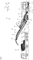
- a soil cultivation machine according to the invention (hereinafter referred to as “machine” for short) is generally designated 10.
- a large road milling machine is shown by way of example as the machine 10 according to the invention, the working device 12 of which is arranged with a milling drum 14 known per se, as is typical for large road milling machines, between the front chassis 16 and the rear chassis 18.
- the chassis 16 and 18, which can be driven for propulsive movement preferably by a hydraulic motor (not shown), are steerable and carry a machine frame 20, which in turn carries the working device 12.
- the machine 10 is thus a self-propelled vehicle.
- the direction of gravity is in the Figures 1 to 3 and 5 to 8 marked with an arrow g.
- the milling drum 14 which rotates orthogonally parallel to the pitch axis Ni of the machine 10, is shielded from the outside environment of the machine 10 by a milling drum box 22 which supports the milling drum 14 so that it can rotate about the rotational axis R.
- the milling drum box 22 is to the ground or underground U on which the machine 10 with the chassis 16 and 18 stands up, and which the milling drum 14 removes in the machining operation, open to enable the intended soil tillage of the machine 10.
- the machine frame 20 is vertically adjustable along the yaw axis Gi via front lifting columns 17 and rear lifting columns 19 with the chassis 16 and 18, whereby, for example, the milling depth t of the milling drum 14 is adjustable.
- the machine 10 can be controlled from a control stand 24.
- the operator's platform 24 can be covered in a manner known per se.
- Soil material removed from the soil U by the milling drum 14 during the intended soil cultivation is conveyed by a transport device 26 from the working device 12 to a delivery location 28, where in the example shown, the machine 10 is traveling ahead at a distance in the direction of the roll axis Ro during the soil cultivation Transport truck 30 is handed over.
- the soil cultivation machine 10, and in the example shown also the transport truck 30, move forward during a soil cultivation in a working direction indicated by the arrow a.
- the transport device 26 comprises a receiving belt 32, which is closer to the working device 12, and a discharge belt 34, which cooperates with the receiving belt 32 and is located further away from the working device 12.
- the receiving belt 32 is rotatable, but is immovably mounted on the machine frame 20 with regard to its orientation relative to the machine frame 20 .
- the receiving belt 32 transfers the material it has conveyed to the discharge belt 34, which conveys the material taken over to the discharge point 28.
- the discharge belt 34 is also rotatable, but can be pivoted relative to the machine frame 20 about a pivot axis S parallel to the yaw axis and preferably inclined about a tilt axis N orthogonal to the pivot axis S, so that the discharge point 28, which coincides with the throwing longitudinal end of the discharge belt 34, is roughly on the surface a spherical or ellipsoidal dome is movable, in order to adapt the delivery location 28 to the respective accompanying vehicle.
- a tilt actuator 43 in the preferred form of at least one fluid-operated, preferably hydraulically operated piston-cylinder arrangement allows the angle of inclination of the discharge belt 34 to be changed from the operator's platform 24.
- the transport device 26 is, but not necessarily fundamentally, encased along its entire length by a housing 38 in order to avoid the external environment of the transport device 26 being polluted by dust and material that may fall from the transport device 26.
- the part of the housing 38 located above the receiving belt 32 is largely realized by the machine frame 20.
- the working device 12 comprises a suction device 40 with a filter device 42.
- the discharge belt 34 as a functional device can be decoupled from the machine frame 20 at a coupling structure 44 in order to be able to reduce the weight of the machine 10 and, with the weight, also its dimensions for transporting the machine 10.
- a cantilevered joint body 46 of the machine frame 20 carries, as a frame-associated joint body 46, two collinear bearing journals 48 which are identical in construction in the example shown and which define the pivot axis S about which the discharge conveyor 34 can pivot relative to the machine frame 20.
- the frame-associated joint body 46 can be formed in one piece with the rest of the machine frame 20, connected to it in a materially bonded manner, or connected to it by separate connecting means, such as screws and nuts, for example.
- a frame-side section 50a of a joint body 50 associated with the device is permanently pivotably mounted on the bearing pin 48.
- the bearing journals 48 and these encompassing bearing bushings 52 which in the example shown are advantageously formed in one piece with the frame-side section 50a of the device-associated joint body 50, form a swivel joint 54.
- the swivel joint 54 is permanent, regardless of the coupling state of the machine frame 20 and the discharge belt 34 connectable functional device.
- the assembly 45 shown on the frame side with respect to the coupling structure 44 is one in FIG Figures 2 to 4 not shown and in the Figures 5 to 8 partially shown device-side assembly 47, comprising a device-side section 50b of the device-associated joint body 50 and the discharge belt 34 connected to it, can be coupled on and uncoupled therefrom.
- the machine 10 Spanning the pivot axis S and the pivot joint 54, the machine 10 comprises an actuator device 55 which, in the example shown, is designed as a hydraulically or pneumatically actuatable piston-cylinder device.
- the actuator device 55 preferably comprises two piston-cylinder devices in the two opposite pivoting directions in order to exert the most symmetrical possible pivoting moments, which when the frame-assigned joint body 46 and the device-assigned joint body 50 are in the extended position, preferably mirror-symmetrically with respect to a plane of symmetry spanned by the yaw axis Gi and the roll axis Ro.
- the actuator device 55 on the side of the machine frame 20 is supported on a support location 57 assigned to the frame and is articulated on the functional device 34 on a pivot point 59 assigned to the device with respect to the pivot axis S.
- the cylinder 55a of the actuator device 55 is supported at the support location 57 and the piston rod 55b is articulated at the articulation location 59.
- the actuator device 55 can also be installed the other way around, but an arrangement of the cylinder 55a to be supplied with fluid closer to the frame is preferred because of the fluid supply which usually takes place from the machine frame 20.
- the entire actuator device is arranged on the frame side and consequently remains unaffected by a coupling or uncoupling process between the machine frame 20 and the functional device 34.
- a frame-side coupling formation 56 is arranged, to which one in the Figures 2 to 4 not shown and in the Figures 5 to 8
- the counter-coupling formation 58 shown of the device-side section 50b of the device-associated joint body 50 is detachable, and preferably can be coupled, without tools, and from which the counter-coupling formation 58, likewise preferably without tools, can be decoupled.
- the coupling formation 56 has a hook 62 as the first form-fit structure 60, with a hook mouth 64 opening along the pivot axis S and counter to the direction of gravity g.
- the hook 62 has a partially cylindrical-concave internal mouth surface 64a, which is essentially orthogonal extends to the pivot axis S, ie the cylinder axis of the partially cylindrical-concave inner jaw surface 64a runs orthogonally to the pivot axis S.
- the inner jaw surface 64a can be a cylindrical-convex rod outer surface 66a of a rod section 66 in the example shown (see Figures 5 to 8 ) as a second form-fit structure 68 of the counter-coupling formation 58 encompass up to 180 ° when the form-fit engagement is established.
- the rod outer surface 66a and the mouth inner surface 64a lie flat against one another when the form-locking engagement is established, so that the width of the hook 62 defines a guide length along which the rod section 66 is held in a defined position.
- an insertion surface 64b is formed, on which the rod section 66 can slide into the hook mouth 64 in contact with it.
- the insertion surface 64b is preferably inclined relative to the pivot axis S about a tilt axis orthogonal to the pivot axis S, so that a pivoting movement of the joint body 50 associated with the device relative to the joint body 46 associated with the frame has as little release effect as possible the positive engagement established between rod section 66 and hook 62.
- the coupling formation 66 also has an abutment structure 70 with a first abutment body 70a and with a second abutment body 70b formed separately therefrom.
- the two contact bodies 70a and 70b are arranged on different sides of the hook 62 and at a distance therefrom in the direction of the yaw axis Gi.
- Each of the contact bodies 70a and 70b has a contact surface section 70a1 and 70b1, respectively, with FIG Figure 2 only the contact surface 70a1 of the contact body 70a can be seen.
- the contact surface sections 70a1 of the contact body 70a and 70b1 (see Figure 4 ) of the contact body 70b, which together form a contact surface 71, are preferably aligned parallel to the pivot axis S in the example shown and, in the extended reference position of the frame-associated body 46 and the frame-side section 50a of the device-associated joint body 50, both along the roll axis Ro and away from the machine frame 20 parallel to the pitch axis Ni away from each other.
- the contact surface sections 70a1 and 70b1 are arranged mirror-symmetrically in the mentioned reference position with respect to the above-mentioned plane of symmetry spanned by the roll axis Ro and the yaw axis Gi.
- a locking device 72 which comprises two locking bolts 74 which can preferably be displaced along the pivot axis S and which are fixed by a holder 76 on the frame-side section 50a of the joint body 50 associated with the device.
- the contact surface sections 70a1 and 70b1 can not only be formed on separate contact bodies 70a and 70b, which are mounted on a plate structure 53 on which the articulation point 59 is also implemented, but the contact surface sections 70a1 and 70b1 can also be formed in one piece with the plate structure 53 of the frame-side section 50a of the device-associated joint body 50 may be formed.
- the locking bolt 74 is guided in each of its operating positions, ie independently of its state of displacement, by an upper guide formation 78a and by a lower guide formation 78b arranged along the yaw axis Gi at a distance from the upper guide formation 78a.
- Both guide formations 78a and 78b are designed as eyelets or through openings which encompass the essentially cylindrical locking bolt 74 along its entire circumference with a clearance fit or with a larger gap as a clearance fit.
- the locking bolt 74 is in Figure 3 shown in its release position, in which the locking device 72 allows coupling and uncoupling of the functional device 34 to the machine frame 20 or from the machine frame 20.
- each locking bolt 74 can be assigned a recess 73a or 73b, in which securing formations 80a and 80b (see FIG Figure 9 ) are arranged in the operational state of the machine 10 in such a way that the device-side securing formations 80a and 80b designed as eyelets or through openings are aligned with the frame-side guide formations 78a and 78b along a line parallel to the pivot axis S.
- each locking bolt 74 of the locking device 72 starting from the in the Figures 3 and 4th
- the release position shown is lowered into its locking position, in which it penetrates both the frame-side guide formations 78a and 78b and the device-side securing formation 80a or 80b assigned to it and thus prevents the counter-coupling formation 58 from pivoting relative to the coupling formation 56 about the rod section 66 received in the hook mouth 64 .
- a contact structure 84 with contact bodies 84a and 84b is shown, the contact body 84a covering the contact body 84b arranged at a distance from it in the direction of the pitch axis Ni.
- both contact bodies 84a and 84b are shown in FIG Figure 9 to recognize.
- the contact bodies 84a and 84b each have a contact surface section 84a1 and 84b1, which form a contact surface 85 and which are designed for contact engagement with the contact surface sections 70a1 and 70b1.
- the contact surface sections 84a1 and 84b1 also run parallel to the pivot axis S and are directed towards one another along the roll axis Ro towards the machine frame 20 and parallel to the pitch axis Ni.
- the machine frame 20 is then raised relative to the deposited discharge belt 34 and thus relative to the counter-coupling formation 58 by the lifting columns 17 alone or 17 and 19, so that the rod section 66 slides into the hook mouth 64 along the insertion surface 64b in positive engagement (see FIG Figure 7 ).
- the hook 62 and with it the rod section 66 and thus the device-side section 50b of the joint body 50 associated with the device, rigidly connected to the rod section 66, are raised further.
- the machine frame 20 is moved forward in the shown extended reference position along the roll axis Ro until the contact surface sections 70a1 and 70b1 with the contact surface sections assigned to them are maintained while the form-fitting engagement between the first and second form-fitting structures 60 and 68 is maintained 84a1 or 84b1 come and remain in contact with the system.
- the securing formations 80a and 80b are aligned with the respectively assigned guide formations 78a and 78b of the respective locking bolt 74.
- the locking bolt 74 can then be shifted from its release position into the locking position and thus secures the coupling between the coupling formation 56 and the counter-coupling formation 58 and thus between the machine frame 20 and the discharge conveyor 34 as the functional device.
- a carrying device 86 is shown as a possible further functional device, which can be coupled to the coupling formation 56 via its counter-coupling formation 58.
- Components or assemblies can be attached to carrying eyes 88 of the carrying device 86, which can then be lifted over the height-adjustable machine frame 20 and moved by the trolleys 16 and 18.
- the soil cultivating machine 10 can move its milling drum 14 via the carrying device 86 at least over short distances, for example from an assembly location to a transport vehicle.
- the counter-coupling formation 58 of the carrying device 86 comprising the rod section 66, the securing formations 80a and 80b and the contact bodies 84a and 84b with contact surfaces 84a1 and 84b1 are identical to a counter-coupling formation 58 of a frame 89 carrying the discharge belt 34 as part of the device-side assembly 47, so that the representation of Figure 9 not only the information about the shape of the counter-coupling formation 58 for the carrying device 86, but also about the shape of the counter-coupling formation 58 for the discharge belt 34 can be found.
Landscapes
- Engineering & Computer Science (AREA)
- Mining & Mineral Resources (AREA)
- Mechanical Engineering (AREA)
- Civil Engineering (AREA)
- Structural Engineering (AREA)
- Architecture (AREA)
- Life Sciences & Earth Sciences (AREA)
- General Life Sciences & Earth Sciences (AREA)
- Geochemistry & Mineralogy (AREA)
- Geology (AREA)
- Agricultural Machines (AREA)
- Disintegrating Or Milling (AREA)
- General Engineering & Computer Science (AREA)
Abstract
Description
- Die vorliegende Erfindung betrifft eine mobile Bodenbearbeitungsmaschine, wie etwa Straßenfräse, Recycler oder Surface-Miner, wobei die Bodenbearbeitungsmaschine in einem für einen Bodenbearbeitungsbetrieb bereiten Bezugszustand umfasst:
- einen Maschinenrahmen,
- eine Mehrzahl von mit dem Maschinenrahmen verbundenen Fahrwerken zur Bereitstellung einer bodengebundenen Mobilität der Bodenbearbeitungsmaschine,
- eine am Maschinenrahmen gehalterte Arbeitsvorrichtung zur Material abtragenden Bearbeitung eines Bereichs eines Bodens,
- eine relativ zum Maschinenrahmen schwenkbeweglich mit dem Maschinenrahmen verbundene, von der Arbeitsvorrichtung verschiedene Funktionsvorrichtung, und
- eine funktional zwischen dem Maschinenrahmen und der Funktionsvorrichtung angeordnete Schwenkgelenkanordnung mit einem rahmenzugeordneten Gelenkkörper, welcher relativ zum Maschinenrahmen unbeweglich mit dem Maschinenrahmen verbunden ist, und mit einem vorrichtungszugeordneten Gelenkkörper, welcher mittels eines Schwenkgelenks um eine Schwenkachse relativ zum rahmenzugeordneten Gelenkkörper schwenkbar mit dem rahmenzugeordneten Gelenkkörper verbunden ist und welcher mit der Funktionsvorrichtung verbunden ist.
- Eine solche Bodenbearbeitungsmaschine ist aus der
WO 2013/048854 A bekannt, welche eine Straßenfräse mit einer eine Fräswalze umfassenden Arbeitsvorrichtung und mit einer Transportvorrichtung als Funktionsvorrichtung zeigt. Die Transportvorrichtung ist um eine zur Gierachse der Bodenbearbeitungsmaschine parallele Schwenkachse schwenkbar am Maschinenrahmen angelenkt und dient zum Abtransport von Fräsgut von der Arbeitsvorrichtung. - Eine weitere Straßenfräse, genauer Straßenkaltfräse, mit einer Transportvorrichtung zum Abtransport von Fräsgut, also abgetragenem Straßenmaterial, als Funktionsvorrichtung ist aus der
US 10,190,270 B2 - Die Transportvorrichtungen zum Abtransport von abgetragenem Bodenmaterial aus der Umgebung der Arbeitsvorrichtung können zusätzlich um bodenparallele Knickachsen knickbar sein, um die Abmessungen der Bodenbearbeitungsmaschine für einen Transport, verglichen mit den Abmessungen der für eine Bodenbearbeitung betriebsbereiten Bodenbearbeitungsmaschine, zu verringern.
- Durch derartige Maßnahmen können, ebenso wie durch ein heb- und senkbares Schutzdach, die Außenabmessungen der Bodenbearbeitungsmaschine verringert werden, nicht jedoch ihr Gewicht.
- In vielen Ländern besteht ein Grenz-Transportgewicht, ab dessen Überschreitung für einen Transport der zu transportierenden Sache eine behördliche Sondergenehmigung zu beantragen ist. Derartige Verwaltungsvorgänge sind zeit- und ressourcenraubend.
- Es ist daher Aufgabe der vorliegenden Erfindung, die eingangs genannte Bodenbearbeitungsmaschine derart weiterzubilden, dass nicht nur ihre Außenabmessungen, sondern auch das Gewicht von als montierter Einheit zu transportierenden Maschinenbestandteilen, ausgehend von dem für eine Bodenbearbeitung betriebsbereiten Bezugszustand der Gesamtmaschine schnell und unkompliziert deutlich verringerbar ist, etwa um ein genehmigungsfreies Maximal-Transportgewicht der Bodenbearbeitungsmaschine nicht zu überschreiten.
- Diese Aufgabe löst die vorliegende Erfindung an einer Bodenbearbeitungsmaschine der eingangs genannten Art dadurch, dass zwischen dem Maschinenrahmen und der Funktionsvorrichtung eine mechanische Kopplungsstruktur ausgebildet ist, mittels welcher die Funktionsvorrichtung bestimmungsgemäß körperlich lösbar mit dem Maschinenrahmen gekoppelt ist, wobei die Kopplungsstruktur eine rahmenseitige Kopplungsformation aufweist, welche mit dem Maschinenrahmen verbunden ist, und eine vorrichtungsseitige Gegenkopplungsformation aufweist, welche mit der Funktionsvorrichtung verbunden ist, wobei die Kopplungsstruktur derart mit Abstand vom Schwenkgelenk ausgebildet ist, dass die rahmenseitige Kopplungsformation und die vorrichtungsseitige Gegenkopplungsformation entweder beide am rahmenzugeordneten Gelenkkörper oder beide am vorrichtungszugeordneten Gelenkkörper ausgebildet sind.
- Somit kann die Funktionsvorrichtung vom Maschinenrahmen körperlich getrennt werden, sodass aus einem einzigen Transportgegenstand, welcher das genehmigungsfreie maximale Transportgewicht überschreitet, mit geringem Aufwand und in kurzer Zeit zwei Transportgegenstände geschaffen werden können, von welchen jeder ein geringeres Gewicht als das genehmigungsfreie maximale Transportgewicht aufweist. Die Möglichkeit zum sofortigen genehmigungsfreien Transport überkompensiert das Erfordernis eines weiteren Transportmittels deutlich.
- Die Relativbeweglichkeit der der beiden Gelenkkörper bleibt durch die Koppelbarkeit von Funktionsvorrichtung und Maschinenrahmen vorteilhaft unbeeinflusst, da das Schwenkgelenk nicht Teil der Kopplungsstruktur ist. Somit entfällt eine wiederholte Demontage und Montage des Schwenkgelenks. Diese wäre aufwendiger, als die erfindungsgemäß vorgesehene Kopplung von Funktionsvorrichtung und Maschinenrahmen unter Beibehaltung des Schwenkgelenks.
- Wird gemäß einer ersten möglichen Ausgestaltung der Erfindung die Kopplungsstruktur im rahmenzugeordneten Gelenkkörper angeordnet, kann eine betragsmäßig vorteilhaft möglichst große Masse vom Maschinenrahmen abgekoppelt werden. Wird gemäß einer weiteren, bevorzugten, Ausgestaltung der Erfindung die Kopplungsstruktur im vorrichtungszugeordneten Gelenkkörper angeordnet, ist zwar die vom Maschinenrahmen abkoppelbare Masse geringfügig geringer als in der oben genannten ersten Ausgestaltung, jedoch kann dann die Montagearbeit für das An- und Abkoppeln der Funktionsvorrichtung verringert sein, was den Masse- und damit Gewichtsnachteil mehr als ausgleicht. Beispielsweise kann dann ein Lösen und ein Verbinden eines rahmenseitig angeordneten, rahmenseitig versorgten und das Schwenkgelenk übergreifenden Verbrauchers entfallen. Ein solcher Verbraucher kann durch eine unten beschriebene Aktuatorvorrichtung oder/und durch eine an wenigstens einem der Gelenkkörper angeordnete Sensorvorrichtung gebildet sein
- Mit dem Begriff "Gelenkkörper" ist eine einseitig funktional von dem Schwenkgelenk ausgehende körperliche Struktur bezeichnet. Diese kann einstückig mit der übrigen einschlägigen Struktur aus Maschinenrahmen und Funktionsvorrichtung verbunden sein. So kann beispielsweise der rahmenzugeordnete Gelenkkörper einstückig mit dem übrigen Maschinenrahmen zusammenhängen. Die beiden Gelenkkörper: rahmenzugeordneter und vorrichtungszugeordneter Gelenkkörper, sind durch das Schwenkgelenk relativ zueinander schwenkbar verbunden. Die Aufteilung der Gelenkkörper sowie der weiter unten genannten Aktuatorvorrichtung-Verbindungsorte: Anlenkort und Abstützort, in einen rahmenzugeordneten und einen vorrichtungszugeordneten Gelenkkörper bzw. Verbindungsort erfolgt mit Bezug auf die Schwenkachse, je nachdem, ob ein Gelenkkörper bzw. ein Verbindungsort bezüglich der Schwenkachse auf der Seite des Maschinenrahmens oder auf der Seite der Funktionsvorrichtung gelegen ist.
- Mit dem Begriff "Kopplung" sowie Begriffen dieser Wortfamilie ist dabei eine Möglichkeit zum bestimmungsgemäßen wiederholten Verbinden und Lösen zweier Bauteile oder Baugruppen oder/und eine bestimmungsgemäß lösbare und erneut herstellbare Verbindung zweier Bauteile oder zweier Baugruppen bezeichnet. Mit Ausnahme der Gelenkkörper sowie der Aktuatorvorrichtung-Verbindungsorte: Anlenkort und Abstützort, bezieht sich die Einteilung weiterer Bauteile und Baugruppen als rahmenseitig oder vorrichtungsseitig auf deren Lage relativ zur Kopplungsstruktur, je nachdem ob das Bauteil bzw. die Baugruppe bezüglich der Kopplungsstruktur auf der Seite des Maschinenrahmens oder auf der Seite der Funktionsvorrichtung gelegen ist.
- Da das Schwenkgelenk mit Abstand von der Kopplungsstruktur angeordnet ist und die Kopplungsstruktur vollständig in einem der Gelenkkörper ausgebildet ist, umfasst wenigstens ein Gelenkkörper aus rahmenzugeordnetem und vorrichtungszugeordnetem Gelenkkörper einen rahmenseitigen und einen vorrichtungsseitigen Gelenckörperabschnitt.
- Wenn im Rahmen dieser Anmeldung von einem betriebsbereiten Zustand der Bodenbearbeitungsmaschine die Rede ist, so ist damit, sofern im Einzelfall nichts Abweichendes ausgesagt ist, ein zur bestimmungsgemäßen Bodenbearbeitung betriebsbereiter Zustand bezeichnet. Sofern die Bodenbearbeitungsmaschine eine mit der Arbeitsvorrichtung kooperierende Transportvorrichtung umfasst, ist auch diese Transportvorrichtung in dem bezeichneten bestimmungsgemäß für die Bodenbearbeitung betriebsbereiten Zustand für ein Zusammenwirken mit der Arbeitsvorrichtung bereit. Im Übrigen wird die Bodenbearbeitungsmaschine in einem Bezugszustand beschrieben, in welchem die Bodenbearbeitungsmaschine zur bestimmungsgemäßen Bodenbearbeitung bereit ist, sofern ausdrücklich nichts Anderes ausgesagt ist. Dabei wird unterstellt, dass die Bodenbearbeitungsmaschine auf einem ebenen horizontalen Untergrund aufsteht.
- Um den Effekt der Gewichtsersparnis in möglichst großem Umfang erzielen zu können, weist die Funktionsvorrichtung bevorzugt ein Gewicht von wenigstens einer Tonne, also 1000 kg, stärker bevorzugt zwischen ein und fünf Tonnen auf. Eine gleichzeitige Abmessungs- und Gewichtsreduktion der Bodenbearbeitungsmaschine in Vorbereitung auf einen Transport kann dadurch erzielt werden, dass die Funktionsvorrichtung wenigstens eine Bodenmaterial-Transportvorrichtung umfasst oder ist. Mit dieser Bodenmaterial-Transportvorrichtung, die beispielsweise ein Transportband oder eine Förderschnecke umfassen kann, wird während der Bodenbearbeitung durch die Arbeitsvorrichtung abgetragenes Bodenmaterial räumlich von der Arbeitsvorrichtung weg gefördert.
- Die Bodenbearbeitungsmaschine kann zur Überwindung längerer Transportstrecken eine mehrteilige Transportvorrichtung aufweisen, beispielsweise umfassend eine Aufnahme-Transportvorrichtung, insbesondere ein umlaufendes Aufnahmetransportband oder kurz "Aufnahmeband". Die Aufnahme-Transportvorrichtung nimmt von der Arbeitsvorrichtung abgetragenes Bodenmaterial auf und transportiert es bis zu einem Übergabeort, wo es einer Abwurf-Transportvorrichtung, insbesondere einem umlaufenden Abwurftransportband oder kurz "Abwurfband" übergeben wird. Die Abwurf-Transportvorrichtung transportiert das Bodenmaterial dann bis zu dem oben genannten Abgabeort. Da in einem solchen Fall von den genannten Transportvorrichtungen in der Regel nur die Abwurf-Transportvorrichtung schwenkbar mit dem Maschinenrahmen verbunden ist, ist bevorzugt die Abwurf-Transportvorrichtung über die Kopplungsstelle mit dem Maschinenrahmen koppelbar, während die Aufnahme-Transportvorrichtung fest am Maschinenrahmen installiert ist.
- Nach dem Abkoppeln der Funktionsvorrichtung vom Maschinenrahmen kann an die verbleibende rahmenseitige Kopplungsformation anstelle der abgekoppelten Funktionsvorrichtung eine von dieser verschiedene weitere Funktionsvorrichtung angekoppelt werden. Diese weitere Funktionsvorrichtung kann der um die frühere Funktionsvorrichtung verminderten Bodenbearbeitungsmaschine die Ausführung von Tätigkeiten eröffnen, zu deren Erfüllung sie im für eine Bodenbearbeitung betriebsbereiten Zustand nicht ausgebildet ist. Somit kann durch die Kopplungsstruktur der Funktionsumfang der Bodenbearbeitungsmaschine erweitert werden. Beispielsweise kann die weitere Funktionsvorrichtung als die oben genannte Funktionsvorrichtung eine Tragevorrichtung umfassen oder sein. Mit der Tragevorrichtung kann die Bodenbearbeitungsmaschine beispielsweise ihre Arbeitsvorrichtung, die für einen Wechsel unterschiedlicher Bearbeitungsarten vorzugsweise lösbar am Maschinenrahmen gehaltert ist, tragen und aufgrund ihrer eigenen Mobilität transportieren und wieder ablegen. Somit kann durch eine solche Tragevorrichtung die Arbeitsvorrichtung ganz oder teilweise losgelöst vom Maschinenrahmen ohne weitere Hilfsmittel bewegt und insbesondere verstaut oder verladen werden, was weiter hilft, das Gewicht des Maschinenrahmens und der an ihm verbleibenden Baugruppen und Aggregate als größte und schwerste zu transportierende Baueinheit der Bodenbearbeitungsmaschine ohne zusätzlichen umfangreichen Werkzeug- und Montageaufwand schnell und unkompliziert zu verringern.
- Die Arbeitsvorrichtung umfasst oder ist bevorzugt eine in Maschinenquerrichtung drehbar in einem vorzugsweise auswechselbar am Maschinenrahmen gehalterten Fräswalzenkasten angeordnete Fräswalze. Eine bevorzugte Fräswalze für Bodenbearbeitungsmaschinen weist ein Fräswalzenrohr auf, auf dessen äußerer Mantelfläche auswechselbare Fräsmeißel in Meißelhaltern aufgenommen sind. Die zur Wartungserleichterung selbst bevorzugt als Meißelwechselhalter ausgebildeten Meißelhalter sind zur Unterstützung der Abfuhr von Fräsgut besonders bevorzugt wendelförmig auf der Mantelfläche angeordnet.
- Die mobile Bodenbearbeitungsmaschine weist bevorzugt einen eigenen Bewegungsantrieb auf und ist somit bevorzugt selbstfahrend, benötigt also kein Zugfahrzeug.
- Grundsätzlich kann die Schwenkachse eine beliebige Orientierung im Raum aufwiesen. Eine bevorzugt einfach herzustellende Kopplung kann dadurch erhalten werden, dass die Schwenkachse parallel zu einer der kartesischen Fahrzeugkoordinatensystemachsen verläuft, also entweder parallel zu der in Maschinenrahmenlängsrichtung bodenparallel verlaufenden Rollachse, oder parallel zu der in Maschinenrahmenquerrichtung bodenparallel verlaufenden Nickachse oder parallel zu der orthogonal zum Boden bzw. Aufstandsuntergrund der Bodenbearbeitungsmaschine verlaufenden Gierachse verläuft. Denn wenigstens in längs der Rollachse und längs der Gierachse ist der Maschinenrahmen durch die Fahrwerke (längs der Rollachse) bzw. durch den Maschinenrahmen bevorzugt mit den Fahrwerken verbindende Hubwerke (längs der Gierachse), insbesondere in Gestalt von Hubsäulen, jeweils isoliert bewegbar und somit einfach und genau steuerbar. Eingeschränkt gilt dies auch für eine isolierte Bewegung längs der Nickachse, etwa wenn die Fahrwerke um 90° aus der Gerade-aus-Stellung in eine Abrollrichtung parallel zur Nickachse lenkbar sind oder wenn die Bodenbearbeitungsmaschine gemäß der
DE102016208246 A1 ausgebildet ist. - Eine besonders einfache Kopplung von Maschinenrahmen und Funktionsvorrichtung ermöglicht eine zur Gierachse der mobilen Bodenbearbeitungsmaschine parallele Schwenkachse, da die Gierachse in den meisten Betriebszuständen etwa parallel zur Schwerkraftwirkungsrichtung verläuft. Somit bewirkt die Schwerkraft bei einer gierachsenparallelen Schwenkachse kein oder nahezu kein zwischen den durch das Schwenkgelenk verbundenen Gelenkkörper wirkendes Schwenkmoment.
- Da die Funktionsvorrichtung, wie oben dargelegt ist, vorteilhafterweise eine große Masse und damit ein großes Gewicht aufweist, ist sie in der Regel nicht allein durch Muskelkraft bewegbar. Die Bodenbearbeitungsmaschine weist daher bevorzugt zur Schwenkverlagerung des vorrichtungszugeordneten Gelenkkörpers relativ zum rahmenzugeordneten Gelenkkörper um die Schwenkachse eine Aktuatorvorrichtung auf. Die Aktuatorvorrichtung kann beispielsweise ein elektrischer Stellmotor oder eine fluidbetriebene Kolben-Zylinder-Anordnung sein.
- Grundsätzlich kann die Aktuatorvorrichtung in beliebiger Weise an der Bodenbearbeitungsmaschine vorgesehen sein. Dies schließt ein, dass die Kopplungsstruktur durch die Aktuatorvorrichtung verlaufen kann und somit die Aktuatorvorrichtung beim Entkoppeln von Maschinenrahmen und Funktionsvorrichtung in einen rahmenseitigen und in einen vorrichtungsseitigen Aktuatorvorrichtungsteil getrennt wird. Bevorzugt soll die Aktuatorvorrichtung jedoch durch die Kopplungsstruktur unbeeinflusst sein, um unnötigen Montage- und Demontageaufwand zu vermeiden. Daher sind bevorzugt sowohl ein rahmenzugeordneter Abstützort als auch ein vorrichtungszugeordneter Anlenkort der Aktuatorvorrichtung auf derselben Seite der Kopplungsstruktur angeordnet. Die Seiten der Kopplungsstruktur sind dabei entweder die Seite der Kopplungsformation oder die Seite der Gegenkopplungsformation. Bevorzugt liegen sowohl Anlenk- als auch Abstützort aufseiten der rahmenseitigen Kopplungsformation bzw. bezüglich der Kopplungsstruktur rahmenseitig, so dass beim Abkoppeln der Funktionsvorrichtung vom Maschinenrahmen die Aktuatorvorrichtung mit ihren zum Maschinenrahmen verlaufenden Energieversorgungs- oder/und Steuerleitungen verbunden bleiben kann.
- Bevorzugt ist die Kopplungsstruktur im vorrichtungszugeordneten Gelenkkörper angeordnet, so dass das Schwenkgelenk auch bei entkoppelter Funktionsvorrichtung mit dem Maschinenrahmen verbunden bleibt.
- Ganz grundsätzlich können die Kopplungsformation und die Gegenkopplungsformation je einen Flansch aufweisen, welche miteinander lösbar verbindbar sind, etwa durch eine Mehrzahl von Schrauben oder Schrauben-Mutter-Kombinationen. Um Gelenkfunktionen durch häufige Demontage und Montage eines Gelenks nicht unerwünscht schnell zu beeinträchtigen, ist bevorzugt weder die Kopplungsformation noch die Gegenkopplungsformation Teil oder Bauteil eines zusätzlich zu dem oben genannten Schwenkgelenk vorgesehenen weiteren Schwenkgelenks derart, dass die Kopplungsformation und die Gegenkopplungsformation im betriebsbereiten Zustand der Bodenbearbeitungsmaschine relativ zueinander schwenkbeweglich zur Ausführung einer bestimmungsgemäßen Relativschwenkbewegung um eine weitere Schwenkachse verbunden wären.
- Sofern die Funktionsvorrichtung relativ zum Maschinenrahmen zusätzlich zum oben genannten Schwenkgelenk um ein weiteres Schwenkgelenk schwenkbar ist, ist die Kopplungsstruktur bevorzugt funktional zwischen dem Schwenkgelenk und dem weiteren Schwenkgelenk angeordnet, so dass das Schwenkgelenk nach einem Abkoppeln der Funktionsvorrichtung vom Maschinenrahmen mit dem Maschinenrahmen verbunden bleibt und dass das weitere Schwenkgelenk mit der Funktionsvorrichtung verbunden bleibt.
- Beispielsweise kann die Funktionsvorrichtung zusätzlich zur Schwenkbarkeit um die oben bevorzugt genannte gierachsenparallele Schwenkachse relativ zum Maschinenrahmen um eine zur Schwenkachse orthogonale Neigeachse als einer weiteren Schwenkachse im obigen Sinne neigbar sein.
- Da die Bodenbearbeitungsmaschine in der Regel einen Neigeaktuator aufweist, um die Neigebewegung der Funktionsvorrichtung relativ zum Maschinenrahmen um die Neigeachse aktuatorisch bewirken zu können, ist es zur Vereinfachung und Reduzierung der für ein Koppeln bzw. Entkoppeln notwendigen Montage- und Demontagearbeit bevorzugt, wenn der Neigeaktuator vollständig vorrichtungsseitig angeordnet ist und auch im abgekoppelten Zustand mit der Funktionsvorrichtung verbunden bleibt. Der Neigeaktuator ist dann lediglich beim An- und Abkoppeln der Funktionsvorrichtung an die vom Maschinenrahmen zugeführte Energieversorgung anzuschließen bzw. von dieser zu trennen. Entsprechendes gilt für eine Signalverbindung zwischen einer rahmenseitigen Steuervorrichtung und dem Neigeaktuator. Auch diese ist beim An- und Abkoppeln herzustellen bzw. zu trennen.
- Bevorzugt sind die Kopplungsformation und die Gegenkopplungsformation jedoch werkzeuglos miteinander koppelbar und voneinander lösbar. Dies kann unter Bildung einer besonders sicheren und dauerhaften Kopplungsverbindung von Maschinenrahmen und Funktionsvorrichtung dadurch erreicht werden, dass eine Formation aus Kopplungsformation und Gegenkopplungsformation eine erste Formschluss-Struktur, wie etwa Haken, Dorn, Kalotte und dergleichen, aufweist. Die jeweils andere Formation aus Kopplungsformation und Gegenkopplungsformation kann dann eine zweite Formschluss-Struktur, wie etwa Stange, Balken, Öse, Kugel und dergleichen, aufweisen. Somit kann zwischen der ersten und der zweiten Formschluss-Struktur ein gegen eine unerwünschte Trennung körperlich sichernder Formschluss hergestellt werden. Um zu vermeiden, dass ein Verschwenken der beiden Gelenkkörper relativ zueinander um die Schwenkachse eine unerwünschte Lösewirkung auf den zwischen der ersten und der zweiten Formschluss-Struktur hergestellten Formschlusseingriff hat, ist ein orthogonal zur Schwenkachse wirkender Formschlusseingriff bevorzugt.
- Gemäß einer bevorzugten konstruktiven Ausgestaltung kann die erste Formschluss-Struktur einen Haken mit einem in Richtung der Schwenkachse offenen Hakenmaul aufweisen, sodass wiederum eine Schwenkbewegung der durch das Schwenkgelenk miteinander verbundenen Gelenkkörper möglichst wenig bzw. keinen lösenden Einfluss auf den zwischen der ersten und der zweiten Formschluss-Struktur hergestellten Formschlusseingriff haben kann. Im Falle einer bevorzugten gierachsenparallelen Schwenkachse öffnet das Hakenmaul dann, wenn es Teil der rahmenseitigen Kopplungsformation ist, bevorzugt entgegen der Schwerkraftwirkungsrichtung, sodass die Schwerkraft den Formschlusseingriff zwischen erster und zweiter Formschluss-Struktur zusätzlich unterstützt. Ist der Haken dagegen Teil der vorrichtungsseitigen Gegenkopplungsformation öffnet das Hakenmaul bei gierachsenparalleler Schwenkachse bevorzugt in Schwerkraftwirkungsrichtung, um die gleiche Unterstützungswirkung zu erzielen.
- Als mit dem Haken formschlüssig wechselwirkendes Gegenteil kann die zweite Formschluss-Struktur einen quer zur Schwenkachse verlaufenden Stangenabschnitt aufweisen. Bevorzugt verläuft der Stangenabschnitt orthogonal zur Schwenkachse mit Abstand von dieser. Jedoch soll nicht ausgeschlossen sein, dass der Stangenabschnitt einen gekrümmten Verlauf aufweist oder von der strengen Orthogonalität abweicht. "Quer" zu einer Bezugsstruktur im Sinne der vorliegenden Anmeldung bedeutet dabei näher an der Orthogonalität als an der Parallelität zur Bezugsstruktur.
- Zur Festlegung des Stangenabschnitts in einem möglichst großen Richtungsbereich kann der Stangenabschnitt im betriebsbereit gekoppelten Zustand von Maschinenrahmen und Funktionsvorrichtung vom Haken umgriffen sein. So kann der Haken den Stangenabschnitt um 180° umgreifen, sodass sich der Stangenabschnitt selbsttätig in das in umgreifende Hakenmaul hineinbewegen, insbesondere hineingleiten kann. Um ein unerwünschtes Herausgleiten des Stangenabschnitts aus dem Hakenmaul wenigstens zu erschweren, verläuft vorzugsweise die Bewegungsbahn, längs welcher der Stangenabschnitt sich in das Hakenmaul hineinbewegen kann, in einem Winkel angestellt zur Schwenkachse. Im bevorzugten Fall einer gierachsenparallel Schwenkachse ist die Bewegungsbahn des Stangenabschnitts bevorzugt um eine zur Schwenkachse orthogonale Neigeachse geneigt, etwa um 5° bis 25°. Zusätzlich oder alternativ kann die Bewegungsbahn eine gekrümmte Bewegungsbahn sein, deren dem Hakenmaul näherliegendes Ende gegenüber der Schwenkachse geneigt ist, bevorzugt in der oben angegebenen Art und Weise geneigt ist. Zur Feststellung des Neigungswinkels zwischen einer gekrümmten Bewegungsbahn und der Schwenkachse kann für den hinsichtlich des Neigungswinkels interessierenden Punkt der Bewegungsbahn die Tangente an die Bewegungsbahn in diesem Punkt herangezogen werden.
- Dabei kann der Haken bereits eine gewisse Führungsfunktion zur Führung des Stangenabschnitts und der den Stangenabschnitt aufweisenden Baugruppe erfüllen, wenn der Haken eine quer zur Schwenkachse verlaufende konkave Maulinnenfläche aufweist, an welcher eine konvexe Außenfläche des Stangenabschnitts bei hergestelltem Formschlusseingriff zwischen erster und zweiter Formschluss-Struktur flächig anliegt. So kann eine Führungsfläche erzielt werden, welche sich quer, insbesondere orthogonal, zur Schwenkachse erstreckt. Eine solche Führungsfläche kann ein relatives Verkippen von Haken und Stangenabschnitt und somit von Maschinenrahmen und Funktionsvorrichtung um eine Kippachse verhindern oder zumindest einschränken, welche sowohl zur Schwenkachse als auch zu der bezüglich der Schwenkachse queren Verlaufsrichtung des Anlagebereichs von Maulinnenfläche und Stangenabschnitts-Außenfläche orthogonal ist.
- Für eine definierte Lageorientierung, insbesondere wiederum werkzeuglose Lageorientierung, von Maschinenrahmen und Funktionsvorrichtung relativ zueinander kann eine Formation aus Kopplungsformation und Gegenkopplungsformation eine Anlage-Struktur mit einer, vorzugsweise freiliegenden, Anlagefläche aufweisen. Weiterhin kann die jeweils andere Formation aus Kopplungsformation und Gegenkopplungsformation eine Kontakt-Struktur mit einer, vorzugsweise freiliegenden, Kontaktfläche aufweisen. Dabei stehen die Anlage-Struktur und die Kontakt-Struktur im betriebsbereit gekoppelten Zustand von Maschinenrahmen und Funktionsvorrichtung in einem in wenigstens einer quer zur Schwenkachse verlaufenden Richtung wirkenden Anlageeingriff miteinander. In diesem Anlageeingriff berühren die Anlagefläche und die Kontaktfläche einander. Daher haben die Normalenvektoren der Anlagefläche und der Kontaktfläche in einem Koordinatensystem mit zur Schwenkachse paralleler axialer Koordinate und mit zur Schwenkachse orthogonaler radialer Koordinate bevorzugt eine größere radiale als axiale Komponente, besonders bevorzugt sind die Normalenvektoren von Anlagefläche und Kontaktfläche ausschließlich orthogonal zur Schwenkachse orientiert.
- Die Anlagefläche kann eine vorteilhafte Ausrichtwirkung zur relativen Ausrichtung von Maschinenrahmen und Funktionsvorrichtung bzw. von Kopplungsformation und Gegenkopplungsformation entfalten, wenn die Anlagefläche wenigstens zwei Anlageflächenabschnitte unterschiedlicher Ausrichtung aufweist. Bevorzugt sind die wenigstens zwei Anlageflächenabschnitte mit einem Winkelabstand um die Schwenkachse angeordnet. Die unterschiedliche Ausrichtung ist vorzugsweise eine Ausrichtung in unterschiedlichen radialen Richtungen, welche miteinander einen Winkel um die Schwenkachse einschließen. Gleiches gilt für die mit der Anlagefläche für einen Anlageeingriff zusammenwirkende Kontaktfläche, welche aus den genannten Gründen wenigstens zwei Kontaktflächenabschnitte unterschiedlicher Ausrichtung aufweist, wobei die wenigstens zwei Kontaktflächenabschnitte mit einem Winkelabstand um die Schwenkachse angeordnet sind. Auch diese unterschiedliche Ausrichtung ist bevorzugt eine Ausrichtung in unterschiedlichen radialen Richtungen, die einen Winkel um die Schwenkachse miteinander einschließen. Um axiale Kraftwirkungen längs der Schwenkachse am Anlageeingriff zu vermeiden, sind besonders bevorzugt die unterschiedlichen Ausrichtungen nur in radialer Ausrichtung unterschiedlich. So können die einen Flächenabschnitte aus Anlageflächenabschnitten und Kontaktflächenabschnitten voneinander oder/und von der Schwenkachse wegweisen und können die jeweils anderen Flächenabschnitte aus Anlageflächenabschnitten und Kontaktflächenabschnitten aufeinander zu oder/und zu der Schwenkachse hinweisen.
- Bevorzugt umfassen Kopplungsformation und Gegenkopplungsformation sowohl die oben genannte erste und zweite Formschluss-Struktur als auch die oben genannte Anlage-Struktur und Kontakt-Struktur, um durch Formschluss eine sichere Verbindung und durch Anlageeingriff eine gezielte relative Ausrichtung von Kopplungsformation und Gegenkopplungsformation zu erzielen. Für eine stabile Anordnung ohne unerwünschte Kraftrückwirkung ist es vorteilhaft, wenn im betriebsbereit gekoppelten Zustand von Maschinenrahmen und Funktionsvorrichtung bezüglich einer zur Schwenkachse orthogonalen Richtung beiderseits der ersten und der zweiten Formschluss-Struktur je wenigstens ein Anlageflächenabschnitt und ein diesen berührender Kontaktflächenabschnitt gelegen sind.
- Grundsätzlich können die Kopplungsformation und die Gegenkopplungsformation ausreichen, um die Funktionsvorrichtung sicher und korrekt ausgerichtet mit dem Maschinenrahmen lösbar zu koppeln. Zur Erhöhung der Betriebssicherheit kann die Bodenbearbeitungsmaschine eine Verriegelungsvorrichtung aufweisen, welche veränderbar ist zwischen einem Verriegelungszustand, in welchem sie die mit dem Maschinenrahmen gekoppelte Funktionsvorrichtung gegen ein Lösen vom Maschinenrahmen sichert, und einem Freigabezustand, in welcher sie ein Lösen der Funktionsvorrichtung vom Maschinenrahmen gestattet.
- Gemäß einer bevorzugten konstruktiven Ausgestaltung kann die Verriegelungsvorrichtung wenigstens ein verlagerbares Verriegelungsglied, wie Verriegelungshaken oder/und Verriegelungsbolzen, aufweisen, welches auf einer Seite der Kopplungsstruktur verlagerbar gelagert ist und welches abhängig von seiner Verlagerungsstellung - Im Falle einer mit dem Maschinenrahmen gekoppelten Funktionsvorrichtung - eine Sicherungsformation auf der jeweils anderen Seite der Kopplungsstruktur hintergreift oder/und durchsetzt.
- Beispielsweise kann die Sicherungsformation der oben genannte Stangenabschnitt sein und kann das Verriegelungsglied ein das oben genannte Hakenmaul je nach seiner Betriebsstellung verschließendes und freigebendes Verschlussbauteil am Haken sein. Zusätzlich oder alternativ kann die Sicherungsformation eine Öse oder ein Sackloch oder eine Durchgangsöffnung sein, in welche das Verriegelungsglied, beispielsweise als verlagerbarer Bolzen, eingeschoben, insbesondere durchsetzend eingeschoben, oder aus welcher das Verriegelungsglied zurückgezogen ist, je nach Betriebsstellung des Verriegelungsglieds.
- Das wenigstens eine Verriegelungsglied ist bevorzugt ein verlagerbarer Bolzen, wie er aus der
DE 10 2016 014 585 A1 bekannt ist. - Unabhängig von der konstruktiven Ausgestaltung von Kopplungsformation und Gegenkopplungsformation kann die mit dem Maschinenrahmen gekoppelte Funktionsvorrichtung dann sicher mit hoher Verriegelungskraft am Maschinenrahmen verriegelt werden, wenn der das Verriegelungsglied tragende Gelenkkörper auf derselben Seite der Kopplungsstruktur, auf welcher das Verriegelungsglied verlagerbar gelagert ist, eine Führungsformation trägt, wobei das Verriegelungsglied dann, wenn es die Sicherungsformation auf der anderen Seite der Kopplungsstruktur am selben Gelenkkörper hintergreift oder/und durchsetzt, auch die Führungsformation hintergreift oder/und durchsetzt. Die Führungsformation kann als Öse oder Durchgangsöffnung ausgebildet sein.
- Gemäß einer bevorzugten Weiterbildung ist das Verriegelungsglied wenigstens auch, vorzugsweise nur, längs der Schwenkachse verlagerbar, so dass eine Schwenkbewegung zwischen Maschinenrahmen und Funktionsvorrichtung eine vom Verriegelungsglied hergestellte Verriegelung möglichst wenig oder nicht lösend beeinflusst.
- Zusätzlich zur körperlich-mechanischen Kopplung von Maschinenrahmen und Funktionsvorrichtung können Maschinenrahmen und Funktionsvorrichtung zur Übertragung von Energie oder/und Signalen gekoppelt sein. Beispielsweise kann der Antrieb der Transportvorrichtung oder/und der oben genannte Neigeaktuator eine Energieversorgung benötigen. Ebenso kann die Transportvorrichtung oder/und insbesondere der Neigeaktuator jeweils einen oder mehrere Sensoren aufweisen, deren Erfassungssignale zu einer rahmenseitigen Steuervorrichtung übertragen werden müssen. Schließlich müssen auch Signale zu der Transportvorrichtung oder/und zum Neigeaktuator übertragbar sein, um deren Betrieb vom Maschinenrahmen aus, etwa von einem Fahrstand aus steuern zu können. Der Betrieb der Funktionsvorrichtung, insbesondere als Transportvorrichtung, kann durch eine elektronische Kamera bilderfassend oder mit geeigneten Betriebssensoren sonst wie überwacht werden. Auch hierfür wird vorrichtungsseitig eine Energie- oder/und Signalübertragung benötigt. Um auch eine solche Kopplung möglichst werkzeugfrei herstellen und lösen zu können, kann zwischen der Funktionsvorrichtung und dem Maschinenrahmen wenigstens eine elektrische Steckverbindung oder/und wenigstens eine fluidische, etwa pneumatische oder/und hydraulische Schnellkupplung angeordnet sein.
- Die vorliegende Erfindung wird nachfolgend anhand der beiliegenden Figuren erläutert werden. Es stellt dar:
- Fig. 1
- eine grobschematische Darstellung einer erfindungsgemäßen Ausführungs-form einer Bodenbearbeitungsmaschine während eines Bodenbearbei-tungsbetriebs,
- Fig. 2
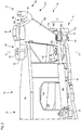
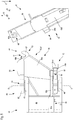
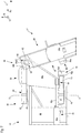
- eine vergrößerte Detailansicht einer Baugruppe aus rahmenzugeordnetem Gelenkkörper und einem mit diesem durch ein Schwenkgelenk verbun-denen rahmenseitigen Abschnitt eines vorrichtungszugeordneten Gelenk-körpers, wobei die Kopplungsformation am rahmenseitigen Abschnitt des vorrichtungszugeordneten Gelenkkörpers ausgebildet ist,
- Fig. 3
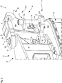
- die Baugruppe von
Figur 2 aus anderer Perspektive, - Fig. 4
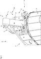
- die Baugruppe von den
Figuren 2 und3 aus wiederum anderer Perspektive, - Fig. 5
- die Baugruppe aus den
Figuren 2 bis 4 und der die Gegenkopplungsforma-tion tragende vorrichtungsseitige Abschnitt des vorrichtungszugeordneten Gelenkkörpers zu Beginn eines Kopplungsvorgangs in Ansicht von der Sei-te, - Fig. 6
- die Baugruppe von
Figur 5 und der die Gegenkopplungsformation tragende vorrichtungsseitige Abschnitt des vorrichtungszugeordneten Gelenkkörpers nach weiterer Annäherung, - Fig. 7
- die Baugruppe von
Figuren 5 und6 und der die Gegenkopplungsformation tragende vorrichtungsseitige Abschnitt des vorrichtungszugeordneten Ge-lenkkörpers nach Herstellung nur eines Formschlusseingriffs zwischen den beteiligten Formschluss-Strukturen von Kopplungsformation und Gegenkopplungsformation, - Fig. 8
- die Baugruppe von
Figuren 5 bis 7 und der die Gegenkopplungsformation tragende vorrichtungsseitige Abschnitt des vorrichtungszugeordneten Gelenkkörpers nach Herstellung sowohl eines Formschlusseingriffs zwischen den beteiligten Formschluss-Strukturen als auch eines Anlageeingriffs zwischen den beteiligten Anlage- und Kontakt-Strukturen von Kopplungsformation und Gegenkopplungsformation, und - Fig.9
- eine grobschematische perspektivische Ansicht einer Tragevorrichtung als einer weiteren bzw. alternativen mit dem Maschinenrahmen koppelbaren Funktionsvorrichtung.
- In
Figur 1 ist eine erfindungsgemäße Bodenbearbeitungsmaschine (nachfolgend kurz als "Maschine" bezeichnet) allgemein mit 10 bezeichnet. Beispielhaft ist als erfindungsgemäße Maschine 10 eine Straßengroßfräse dargestellt, deren Arbeitsvorrichtung 12 mit einer an sich bekannten Fräswalze 14, wie für Straßengroßfräsen typisch, zwischen den vorderen Fahrwerken 16 und den hinteren Fahrwerken 18 angeordnet ist. Die jeweils vorzugsweise durch einen nicht dargestellten Hydromotor zur Vortriebsbewegung antreibbaren Fahrwerke 16 und 18 sind lenkbar und tragen einen Maschinenrahmen 20, welcher wiederum die Arbeitsvorrichtung 12 trägt. Die Maschine 10 ist somit ein selbstfahrendes Fahrzeug. - Die Schwerkraftwirkungsrichtung ist in den
Figuren 1 bis 3 und5 bis 8 mit einem Pfeil g gekennzeichnet. - Die um eine zur Zeichenebene von
Figur 1 orthogonale, parallel zur Nickachse Ni der Maschine 10 verlaufende Rotationsachse R rotierbare Fräswalze 14 ist durch einen Fräswalzenkasten 22, welcher die Fräswalze 14 um die Rotationsachse R rotierbar lagert, zur Außenumgebung der Maschine 10 abgeschirmt. Der Fräswalzenkasten 22 ist zum Boden bzw. Untergrund U, auf welchem die Maschine 10 mit den Fahrwerken 16 und 18 aufsteht, und welchen die Fräswalze 14 im Bearbeitungsbetrieb abträgt, hin offen, um die bestimmungsgemäße Bodenbearbeitung der Maschine 10 zu ermöglichen. - Der Maschinenrahmen 20 ist längs der Gierachse Gi höhenverstellbar über vordere Hubsäulen 17 und hintere Hubsäulen 19 mit den Fahrwerken 16 und 18 verbunden, wodurch beispielsweise die Frästiefe t der Fräswalze 14 einstellbar ist.
- Die Maschine 10 ist von einem Fahrstand 24 aus steuerbar. Der Fahrstand 24 kann in an sich bekannter Weise überdacht sein.
- Von der Fräswalze 14 während der bestimmungsgemäßen Bodenbearbeitung vom Boden U abgetragenes Bodenmaterial wird von einer Transportvorrichtung 26 von der Arbeitsvorrichtung 12 zu einem Abgabeort 28 gefördert, wo es im dargestellten Beispiel einem die Maschine 10 während der Bodenbearbeitung mit Abstand in Richtung der Rollachse Ro vorausfahrend-begleitenden Transport-Lkw 30 übergeben wird. Die Bodenbearbeitungsmaschine 10, und im dargestellten Beispiel auch der Transport-Lkw 30, bewegen sich während einer Bodenbearbeitung in einer durch den Pfeil a gekennzeichneten Arbeitsrichtung vorwärts.
- Die Transportvorrichtung 26 umfasst ein näher bei der Arbeitsvorrichtung 12 gelegenes Aufnahmeband 32 und ein mit dem Aufnahmeband 32 kooperierendes, weiter von der Arbeitsvorrichtung 12 entfernt gelegenes Abwurfband 34. Das Aufnahmeband 32 ist umlauffähig, aber hinsichtlich seiner relativen Orientierung zum Maschinenrahmen 20 unveränderlich am Maschinenrahmen 20 gelagert. An einer Übergabestelle 36 übergibt das Aufnahmeband 32 das von ihm geförderte Material an das Abwurfband 34, welches das übernommene Material bis zum Abgabeort 28 fördert. Das Abwurfband 34 ist ebenfalls umlauffähig, jedoch relativ zum Maschinenrahmen 20 um eine gierachsenparallele Schwenkachse S schwenkbar und bevorzugt um eine zur Schwenkachse S orthogonale Neigeachse N neigbar, sodass der Abgabeort 28, welcher mit dem abwerfenden Längsende des Abwurfbands 34 zusammenfällt, in etwa auf der Oberfläche einer Kugel- oder Ellipsoidkalotte beweglich ist, um den Abgabeort 28 an das jeweilige Begleitfahrzeug anzupassen. Ein Neigeaktuator 43 in bevorzugter Gestalt wenigstens einer fluidbetriebenen, vorzugsweise hydraulisch betriebenen Kolben-Zylinder-Anordnung gestattet eine Veränderung des Neigungswinkels des Abwurfbandes 34 vom Fahrstand 24 aus.
- Die Transportvorrichtung 26 ist im dargestellten Beispiel, jedoch nicht notwendigerweise grundsätzlich, längs ihrer gesamten Länge durch eine Einhausung 38 eingehaust, um eine Belastung der Außenumgebung der Transportvorrichtung 26 durch Staub und durch von der Transportvorrichtung 26 möglicherweise herabfallendes Material zu vermeiden. Der über dem Aufnahmeband 32 gelegene Teil der Einhausung 38 ist größtenteils durch den Maschinenrahmen 20 realisiert.
- Zur weiteren Verringerung der Schmutzemission, insbesondere Staubemission, der Maschine 10 durch die Arbeitsvorrichtung 12 umfasst diese eine Absaugeinrichtung 40 mit einer Filtervorrichtung 42.
- An einer Kopplungsstruktur 44 ist das Abwurfband 34 als Funktionsvorrichtung vom Maschinenrahmen 20 abkoppelbar, um das Gewicht der Maschine 10 und mit dem Gewicht auch deren Abmessungen für einen Transport der Maschine 10 verringern zu können.
- Eine bezüglich der Kopplungsstruktur 44 rahmenseitige Baugruppe 45 wird nachfolgend anhand der
Figuren 2 bis 4 näher erläutert. - Ein auskragender Gelenkkörper 46 des Maschinenrahmens 20 trägt als rahmenzugeordneter Gelenkkörper 46 zwei im dargestellten Beispiel baugleiche kollineare Lagerzapfen 48, welche die Schwenkachse S definieren, um die das Abwurfband 34 relativ zum Maschinenrahmen 20 schwenkbar ist. Der rahmenzugeordnete Gelenckörper 46 kann einstückig mit dem übrigen Maschinenrahmen 20 ausgebildet, mit diesem stoffschlüssig verbunden oder mit diesem durch gesonderte Verbindungsmittel, wie beispielsweise Schrauben und Muttern, verbunden sein.
- An den Lagerzapfen 48 ist ein rahmenseitiger Abschnitt 50a eines vorrichtungszugeordneten Gelenkkörpers 50 dauerhaft schwenkbar gelagert. Die Lagerzapfen 48 und diese umgreifende Lagerbuchsen 52, welche im dargestellten Beispiel vorteilhaft einstückig mit dem rahmenseitigen Abschnitt 50a des vorrichtungszugeordneten Gelenkkörpers 50 ausgebildet sind, bilden ein Schwenkgelenk 54. Das Schwenkgelenk 54 besteht dauerhaft, unabhängig vom Kopplungszustand des Maschinenrahmen 20 und des Abwurfbands 34 als der koppelbaren Funktionsvorrichtung.
- An die in
Figur 2 dargestellte, bezüglich der Kopplungsstruktur 44 rahmenseitige Baugruppe 45 ist eine in denFiguren 2 bis 4 nicht dargestellte und in denFiguren 5 bis 8 teilweise dargestellte vorrichtungsseitige Baugruppe 47, umfassend einen vorrichtungsseitigen Abschnitt 50b des vorrichtungszugeordneten Gelenkkörpers 50 und das damit verbundene Abwurfband 34, ankoppelbar und von dieser abkoppelbar. - Die Schwenkachse S und das Schwenkgelenk 54 übergreifend, umfasst die Maschine 10 eine Aktuatorvorrichtung 55, welche im dargestellten Beispiel als hydraulisch oder pneumatisch betätigbare Kolben-Zylinder-Vorrichtung ausgebildet ist. Bevorzugt umfasst die Aktuatorvorrichtung 55 zur Ausübung möglichst symmetrischer Schwenkmomente in beiden entgegengesetzten Schenksinnen zwei Kolben-Zylinder-Vorrichtungen, die bei gestreckter Stellung von rahmenzugeordnetem Gelenckörper 46 und vorrichtungszugeordnetem Gelenkkörper 50 bevorzugt spiegelsymmetrisch bezüglich einer durch die Gierachse Gi und die Rollachse Ro aufgespannten Symmetrieebene angeordnet sind. Die Aktuatorvorrichtung 55 aufseiten des Maschinenrahmens 20 ist an einem rahmenzugeordneten Abstützort 57 abgestützt und ist aufseiten der Funktionsvorrichtung 34 an einem bezüglich der Schwenkachse S vorrichtungszugeordneten Anlenkort 59 angelenkt. Im dargestellten Beispiel ist der Zylinder 55a der Aktuatorvorrichtung 55 am Abstützort 57 abgestützt und ist die Kolbenstange 55b am Anlenkort 59 angelenkt. Die Aktuatorvorrichtung 55 kann auch umgekehrt eingebaut sein, jedoch ist eine rahmennähere Anordnung des mit Fluid zu versorgenden Zylinders 55a wegen der in der Regel vom Maschinenrahmen 20 aus erfolgenden Fluidversorgung bevorzugt.
- Die gesamte Aktuatorvorrichtung ist rahmenseitig angeordnet und bleibt folglich von einem An- bzw. Abkoppelvorgang zwischen Maschinenrahmen 20 und Funktionsvorrichtung 34 unbeeinflusst.
- An dem von der Schwenkachse S entfernt gelegenen Endbereich 50a1 des rahmenseitigen Abschnitts 50a des vorrichtungszugeordneten Gelenkkörpers 50 ist eine rahmenseitige Kopplungsformation 56 angeordnet, an welche eine in den
Figuren 2 bis 4 nicht dargestellte und in denFiguren 5 bis 8 dargestellte Gegenkopplungsformation 58 des vorrichtungsseitigen Abschnitts 50b des vorrichtungszugeordneten Gelenkkörpers 50 lösbar, und bevorzugt werkzeuglos, ankoppelbar und von welcher die Gegenkopplungsformation 58, ebenso bevorzugt werkzeuglos, abkoppelbar ist. - Die Kopplungsformation 56 weist als erste Formschluss-Struktur 60 einen Haken 62 auf, mit einem längs der Schwenkachse S und entgegen der Schwerkraftwirkungsrichtung g öffnenden Hakenmaul 64. Der Haken 62 weist im dargestellten Ausführungsbeispiel eine teilzylindrisch-konkave Maulinnenfläche 64a auf, welche sich im Wesentlichen orthogonal zur Schwenkachse S erstreckt, d. h. die Zylinderachse der teilzylindrische-konkave Maulinnenfläche 64a verläuft orthogonal zur Schwenkachse S. Damit kann die Maulinnenfläche 64a eine im dargestellten Beispiel zylindrisch-konvexe Stangenaußenfläche 66a eines Stangenabschnitts 66 (siehe
Figuren 5 bis 8 ) als eine zweite Formschluss-Struktur 68 der Gegenkopplungsformation 58 bei hergestelltem Formschlusseingriff um bis zu 180° umgreifen. Die Stangenaußenfläche 66a und die Maulinnenfläche 64a liegen bei hergestelltem Formschlusseingriff flächig aneinander an, sodass die Breite des Hakens 62 eine Führungslänge definiert, längs welcher der Stangenabschnitt 66 lagedefiniert gehalten ist. - Auf der näher beim Maschinenrahmen 20 gelegenen Seite des Hakens 62 ist eine Einführfläche 64b ausgebildet, an welcher anliegend der Stangenabschnitt 66 in das Hakenmaul 64 hineingleiten kann. Die Einführfläche 64b ist relativ zur Schwenkachse S bevorzugt um eine zur Schwenkachse S orthogonale Neigeachse geneigt, sodass eine Schwenkbewegung des vorrichtungszugeordneten Gelenkkörpers 50 relativ zum rahmenzugeordneten Gelenkkörper 46 möglichst keine Lösewirkung auf den zwischen Stangenabschnitt 66 und Haken 62 hergestelltem Formschlusseingriff hat.
- Die Kopplungsformation 66 weist außerdem eine Anlage-Struktur 70 auf mit einem ersten Anlagekörper 70a und mit einem gesondert davon ausgebildeten zweiten Anlagekörper 70b. Die beiden Anlagekörper 70a und 70b sind auf unterschiedlichen Seiten des Hakens 62 und in Richtung der Gierachse Gi mit Abstand von diesem angeordnet. Jeder der Anlagekörper 70a und 70b weist einen Anlageflächenabschnitt 70a1 bzw. 70b1 auf, wobei in
Figur 2 lediglich die Anlagefläche 70a1 des Anlagekörpers 70a zu erkennen ist. Die Anlageflächenabschnitte 70a1 des Anlagekörpers 70a sowie 70b1 (sieheFigur 4 ) des Anlagekörpers 70b, welche gemeinsam eine Anlagefläche 71 bilden, sind im dargestellten Beispiel bevorzugt parallel zur Schwenkachse S ausgerichtet und weisen bei gestreckter Bezugsstellung von rahmenzugeordnetem Gelenkkörper 46 und rahmenseitigem Abschnitt 50a des vorrichtungszugeordneten Gelenkkörpers 50 sowohl längs der Rollachse Ro vom Maschinenrahmen 20 weg als auch parallel zur Nickachse Ni voneinander weg. Die Anlageflächenabschnitte 70a1 und 70b1 sind in der genannten Bezugsstellung bezüglich der oben genannten durch die Rollachse Ro und die Gierachse Gi aufgespannten Spiegelsymmetrieebene spiegelsymmetrisch angeordnet. - In
Figur 3 ist die Aktuatorvorrichtung 55 aus Gründen besserer Übersichtlichkeit weggelassen. Dafür ist eine Verriegelungsvorrichtung 72 gezeigt, welche zwei vorzugsweise längs der Schwenkachse S verlagerbare Verriegelungsbolzen 74 umfasst, die durch eine Halterung 76 am rahmenseitigen Abschnitt 50a des vorrichtungszugeordneten Gelenkkörpers 50 festgelegt sind. - Abweichend von der Darstellung von
Figur 2 können die Anlageflächenabschnitte 70a1 und 70b1 nicht nur an gesonderten Anlagekörper 70a und 70b ausgebildet sein, die an eine Plattenstruktur 53 anmontiert sind, an welcher auch der Anlenkort 59 realisiert ist, sondern können die Anlageflächenabschnitte 70a1 und 70b1 auch einstückig mit der Plattenstruktur 53 des rahmenseitigen Abschnitts 50a des vorrichtungszugeordneten Gelenkkörpers 50 ausgebildet sein. - Der Verriegelungsbolzen 74 ist in jeder seiner Betriebsstellungen, also unabhängig von seinem Verlagerungszustand, durch eine obere Führungsformation 78a und durch eine längs der Gierachse Gi mit Abstand von der oberen Führungsformation 78a angeordnete untere Führungsformation 78b geführt. Beide Führungsformationen 78a und 78b sind als Ösen oder Durchgangsöffnungen ausgebildet, welche den im Wesentlichen zylindrischen Verriegelungsbolzen 74 längs seines gesamten Umfangs mit Spielpassung oder mit größerem Spaltmaß als Spielpassung umgreifen. Der Verriegelungsbolzen 74 ist in
Figur 3 in seiner Freigabestellung gezeigt, in welcher die Verriegelungsvorrichtung 72 ein Ankoppeln und ein Abkoppeln der Funktionsvorrichtung 34 an den Maschinenrahmen 20 bzw. vom Maschinenrahmen 20 gestattet. - In Figur vier ist auf der Unterseite der Plattenstruktur 73 jedem Verriegelungsbolzen 74 zugeordnet eine Ausnehmung 73a bzw. 73b erkennbar, in welchen Sicherungsformationen 80a und 80b (siehe
Figur 9 ) im betriebsbereiten Zustand der Maschine 10 derart angeordnet sind, dass die als Ösen oder Durchgangsöffnungen ausgebildeten vorrichtungsseitigen Sicherungsformationen 80a und 80b mit den rahmenseitigen Führungsformationen 78a und 78b längs einer Parallelen zur Schwenkachse S fluchten. In dieser fluchtenden Anordnung kann jeder Verriegelungsbolzen 74 der Verriegelungsvorrichtung 72 ausgehend von der in denFiguren 3 und4 gezeigten Freigabestellung in seine Verriegelungsstellung abgesenkt werden, in welcher er sowohl die rahmenseitigen Führungsformationen 78a und 78b als auch die ihm jeweils zugeordnete vorrichtungsseitige Sicherungsformation 80a oder 80b durchsetzt und so ein Schwenken der Gegenkopplungsformation 58 relativ zur Kopplungsformation 56 um den im Hakenmaul 64 aufgenommenen Stangenabschnitt 66 verhindert. - In den
Figuren 3 und4 ist die schürzenartige Verkleidung 82 an der Übergabestelle 36 vom Aufnahmeband 32 auf das Abwurfband 34 dargestellt. - In den
Figuren 5 bis 8 ist ein Ankopplungsvorgang gezeigt, bei welchem der vorrichtungsseitige Abschnitt 50b des vorrichtungszugeordneten Gelenkkörpers 50 mit seiner Gegenkopplungsformation 58 an die Kopplungsformation 56 des rahmenseitigen Abschnitts 50a desselben vorrichtungszugeordneten Gelenkkörpers 50 angekoppelt wird. - In der Seitenansicht der
Figuren 5 bis 8 ist eine Kontakt-Struktur 84 mit Kontaktkörpern 84a und 84b dargestellt, wobei der Kontaktkörper 84a den von ihm in Richtung der Nickachse Ni mit Abstand angeordneten Kontaktkörper 84b verdeckt. Beide Kontaktkörper 84a und 84b sind jedoch inFigur 9 zu erkennen. Die Kontaktkörper 84a und 84b weisen jeweils einen Kontaktflächenabschnitt 84a1 und 84b1 auf, welche eine Kontaktfläche 85 bilden und welche zum Anlageeingriff mit den Anlageflächenabschnitten 70a1 und 70b1 ausgebildet sind. Im betriebsbereiten Zustand der Maschine 10 verlaufen auch die Kontaktflächenabschnitte 84a1 und 84b1 parallel zur Schwenkachse S und sind längs der Rollachse Ro zum Maschinenrahmen 20 hin und parallel zur Nickachse Ni aufeinander zu gerichtet. - Ausgehend von dem in
Figur 5 gezeigten vollständig entkoppelten Zustand wird der Maschinenrahmen 20 durch die Fahrwerke 16 und 18 auf die gegen Kopplungsvorrichtung 58 des gelegten Abwurfbandes 34 zu bewegt, bis die Außenfläche 66a des Stangenabschnitts 66 an der Einführfläche 64b anliegt (sieheFigur 6 ). - Anschließend wird der Maschinenrahmen 20 relativ zum abgelegten Abwurfband 34 und damit relativ zur Gegenkopplungsformation 58 durch die Hubsäulen 17 alleine oder 17 und 19 angehoben, sodass der Stangenabschnitt 66 entlang der Einführfläche 64b in Formschlusseingriff in das Hakenmaul 64 gleitet (siehe
Figur 7 ). - Ausgehend von diesem erreichten Formschlusseingriff der Formschluss-Strukturen 60 und 68 wird der Haken 62 und mit ihm der Stangenabschnitt 66 und somit der starr mit dem Stangenabschnitt 66 verbundene vorrichtungsseitige Abschnitt 50b des vorrichtungszugeordneten Gelenkkörpers 50 weiter angehoben. Gegebenenfalls wird der Maschinenrahmen 20 in der gezeigten gestreckten Bezugsstellung längs der Rollachse Ro vorwärts bewegt, bis unter Aufrechterhaltung des Formschlusseingriffs zwischen der ersten und der zweiten Formschluss-Struktur 60 bzw. 68 die Anlageflächenabschnitte 70a1 und 70b1 mit den ihnen zugeordneten Kontaktflächenabschnitten 84a1 bzw. 84b1 in Anlageeingriff gelangen und verbleiben. In diesem hergestellten Anlageeingriff fluchten die Sicherungsformationen 80a bzw. 80b mit den jeweils zugeordneten Führungsformationen 78a und 78b des jeweiligen Verriegelungsbolzens 74. Der Verriegelungsbolzen 74 kann dann von seiner Freigabestellung in die Verriegelungsstellung verlagert werden und sichert somit die Kopplung zwischen Kopplungsformation 56 und Gegenkopplungsformation 58 und damit zwischen Maschinenrahmen 20 und dem Abwurfband 34 als der Funktionsvorrichtung.
- Für den gesamten Prozess des Ankoppelns - ebenso wie für den entgegengesetzt gerichteten Prozess des Abkoppelns - ist erkennbar keinerlei Werkzeug notwendig, sondern das Ankoppeln und Abkoppeln kann alleine durch Bordmittel der Bodenbearbeitungsmaschine 10, umfassend den Maschinenrahmen 20, die Funktionsvorrichtung 34 sowie die durch das Schwenkgelenk 54 miteinander schwenkbar verbundenen Gelenkkörper 46 und 50, erzielt werden.
- In
Figur 9 ist eine Tragevorrichtung 86 als mögliche weitere Funktionsvorrichtung dargestellt, die über ihre Gegenkopplungsformation 58 mit der Kopplungsformation 56 koppelbar ist. An Trageösen 88 der Tragevorrichtung 86 können Bauteile oder Baugruppen angehängt werden, die dann über den höhenverstellbaren Maschinenrahmen 20 angehoben und durch die Fahrwerke 16 und 18 bewegt werden können. Beispielsweise kann die Bodenbearbeitungsmaschine 10 ihre Fräswalze 14 über die Tragevorrichtung 86 zumindest über geringe Distanzen, etwa von einem Montageort bis zu einem Transportfahrzeug bewegen. - Die Gegenkopplungsformation 58 der Tragevorrichtung 86, umfassend den Stangenabschnitt 66, die Sicherungsformationen 80a und 80b sowie die Kontaktkörper 84a und 84b mit Kontaktflächen 84a1 und 84b1 sind identisch wie eine Gegenkopplungsformation 58 eines das Abwurfband 34 tragenden Gestells 89 als Teil der vorrichtungsseitigen Baugruppe 47 ausgebildet, sodass der Darstellung von
Figur 9 nicht nur die Information über die Gestalt der Gegenkupplungsformation 58 für die Tragevorrichtung 86, sondern auch über die Gestalt der Gegenkopplungsformation 58 für das Abwurfband 34 zu entnehmen ist.
Claims (15)
- Mobile Bodenbearbeitungsmaschine (10), wie etwa Straßenfräse, Recycler oder Surface-Miner, wobei die Bodenbearbeitungsmaschine (10) in einem für einen Bodenbearbeitungsbetrieb bereiten Bezugszustand umfasst:- einen Maschinenrahmen (20),- eine Mehrzahl von mit dem Maschinenrahmen (20) verbundenen Fahrwerken (16, 18) zur Bereitstellung einer bodengebundenen Mobilität der Bodenbearbeitungsmaschine (10),- eine am Maschinenrahmen (20) gehalterte Arbeitsvorrichtung (12) zur Material abtragenden Bearbeitung eines Bereichs eines Bodens (U),- eine relativ zum Maschinenrahmen (20) schwenkbeweglich mit dem Maschinenrahmen (20) verbundene, von der Arbeitsvorrichtung (12) verschiedene Funktionsvorrichtung (34, 86), und- eine funktional zwischen dem Maschinenrahmen (20) und der Funktionsvorrichtung (34, 86) angeordnete Schwenkgelenkanordnung mit einem rahmenzugeordneten Gelenkkörper (46), welcher relativ zum Maschinenrahmen (20) unbeweglich mit dem Maschinenrahmen (20) verbunden ist, und mit einem vorrichtungszugeordneten Gelenkkörper (50), welcher mittels eines Schwenkgelenks (54) um eine Schwenkachse (S) relativ zum rahmenzugeordneten Gelenkkörper (46) schwenkbar mit dem rahmenzugeordneten Gelenkkörper (46) verbunden ist und welcher mit der Funktionsvorrichtung (34, 86) verbunden ist,
dadurch gekennzeichnet, dass zwischen dem Maschinenrahmen (20) und der Funktionsvorrichtung (34, 86) eine mechanische Kopplungsstruktur (44) ausgebildet ist, mittels welcher die Funktionsvorrichtung (34, 86) bestimmungsgemäß körperlich lösbar mit dem Maschinenrahmen (20) gekoppelt ist, wobei die Kopplungsstruktur (44) eine rahmenseitige Kopplungsformation (56) aufweist, welche mit dem Maschinenrahmen (20) verbunden ist, und eine vorrichtungsseitige Gegenkopplungsformation (58) aufweist, welche mit der Funktionsvorrichtung (34, 86) verbunden ist, wobei die Kopplungsstruktur (44) derart mit Abstand vom Schwenkgelenk (54) ausgebildet ist, dass die rahmenseitige Kopplungsformation (56) und die vorrichtungsseitige Gegenkopplungsformation (58) entweder beide am rahmenzugeordneten Gelenkkörper (46) oder beide am vorrichtungszugeordneten Gelenkkörper (50) ausgebildet sind. - Mobile Bodenbearbeitungsmaschine (10) nach Anspruch 1,
dadurch gekennzeichnet, dass die Funktionsvorrichtung (34, 86) wenigstens eine Vorrichtung aus Bodenmaterial-Transportvorrichtung (34) und Tragevorrichtung (86) umfasst. - Mobile Bodenbearbeitungsmaschine (10) nach Anspruch 1 oder 2,
dadurch gekennzeichnet, dass die Schwenkachse (S) parallel zu einer Gierachse (Gi) der mobilen Bodenbearbeitungsmaschine (10) verläuft. - Mobile Bodenbearbeitungsmaschine (10) nach einem der vorhergehenden Ansprüche,
dadurch gekennzeichnet, dass die Bodenbearbeitungsmaschine (10) zur Schwenkverlagerung des vorrichtungszugeordneten Gelenkkörpers (50) relativ zum rahmenzugeordneten Gelenkkörper (46) um die Schwenkachse (S) eine Aktuatorvorrichtung (55) aufweist, wobei sowohl ein rahmenzugeordneter Abstützort (57) als auch ein vorrichtungszugeordneter Anlenkort (59) der Aktuatorvorrichtung (55) auf derselben Seite der Kopplungsstruktur (44) angeordnet sind. - Mobile Bodenbearbeitungsmaschine (10) nach einem der vorhergehenden Ansprüche,
dadurch gekennzeichnet, dass eine Formation aus Kopplungsformation (56) und Gegenkopplungsformation (58) eine erste Formschluss-Struktur (60), wie Haken (62), Dorn, Kalotte und dergleichen, aufweist, und dass die jeweils andere Formation aus Kopplungsformation (56) und Gegenkopplungsformation (58) eine zweite Formschluss-Struktur (68), wie etwa Stange (66), Balken, Öse, Kugel und dergleichen, aufweist, wobei die erste (60) und die zweite Formschluss-Struktur (68) im betriebsbereit gekoppelten Zustand von Maschinenrahmen (20) und Funktionsvorrichtung (34, 86) in einem in wenigstens einer zur Schwenkachse (S) orthogonalen Richtung wirkenden Formschlusseingriff miteinander stehen. - Mobile Bodenbearbeitungsmaschine (10) nach Anspruch 5,
dadurch gekennzeichnet, dass die erste Formschluss-Struktur (60) einen Haken (62) mit einem in Richtung der Schwenkachse (S) offenen Hakenmaul (64) aufweist, und dass die zweite Formschluss-Struktur (68) einen quer zur Schwenkachse (S) verlaufenden Stangenabschnitt (66) aufweist, wobei der Stangenabschnitt (66) im betriebsbereit gekoppelten Zustand von Maschinenrahmen (20) und Funktionsvorrichtung (34, 86) vom Haken (62) umgriffen ist. - Mobile Bodenbearbeitungsmaschine (10) nach Anspruch 6,
dadurch gekennzeichnet, dass der Haken (62) eine quer zur Schwenkachse (S) verlaufende konkave Maulinnenfläche (64a) aufweist, an welcher eine konvexe Außenfläche (66a) des Stangenabschnitts (66) bei hergestelltem Formschlusseingriff zwischen erster (60) und zweiter Formschluss-Struktur (68) flächig anliegt. - Mobile Bodenbearbeitungsmaschine (10) nach einem der vorhergehenden Ansprüche,
dadurch gekennzeichnet, dass eine Formation aus Kopplungsformation (56) und Gegenkopplungsformation (58) eine Anlage-Struktur (70) mit einer Anlagefläche (71) aufweist, und dass die jeweils andere Formation aus Kopplungsformation (56) und Gegenkopplungsformation (58) eine Kontakt-Struktur (84) mit einer Kontaktfläche (85) aufweist, wobei die Anlage-Struktur (70) und die Kontakt-Struktur (84) im betriebsbereit gekoppelten Zustand von Maschinenrahmen (20) und Funktionsvorrichtung (34, 86) in einem in wenigstens einer quer zur Schwenkachse (S) verlaufenden Richtung wirkenden Anlageeingriff miteinander stehen, in welchem die Anlagefläche (71) und die Kontaktfläche (85) einander berühren. - Mobile Bodenbearbeitungsmaschine (10) nach Anspruch 8,
dadurch gekennzeichnet, dass die Anlagefläche (71) wenigstens zwei Anlageflächenabschnitte (70a1, 70b1) unterschiedlicher Ausrichtung aufweist, wobei die wenigstens zwei Anlageflächenabschnitte (70a1, 70b1) mit einem Winkelabstand um die Schwenkachse (S) angeordnet sind, und dass die Kontaktfläche (85) wenigstens zwei Kontaktflächenabschnitte (84a1, 84b1) unterschiedlicher Ausrichtung aufweist, wobei die wenigstens zwei Kontaktflächenabschnitte (84a1, 84b1) mit einem Winkelabstand um die Schwenkachse (S) angeordnet sind, - Mobile Bodenbearbeitungsmaschine (10) nach Anspruch 9, unter Einbeziehung des Anspruchs 5,
dadurch gekennzeichnet, dass im betriebsbereit gekoppelten Zustand von Maschinenrahmen (20) und Funktionsvorrichtung (34, 86) bezüglich einer zur Schwenkachse (S) orthogonalen Richtung beiderseits der ersten und der zweiten Formschluss-Struktur (60) je wenigstens ein Anlageflächenabschnitt (70a1, 70b1) und ein diesen berührender Kontaktflächenabschnitt (84a1, 84b1) gelegen sind. - Mobile Bodenbearbeitungsmaschine (10) nach einem der vorhergehenden Ansprüche,
dadurch gekennzeichnet, dass sie eine Verriegelungsvorrichtung (72) aufweist, welche veränderbar ist zwischen einem Verriegelungszustand, in welchem sie die mit dem Maschinenrahmen (20) gekoppelte Funktionsvorrichtung (34, 86) gegen ein Lösen vom Maschinenrahmen (20) sichert, und einem Freigabezustand, in welcher sie ein Lösen der Funktionsvorrichtung (34, 86) vom Maschinenrahmen (20) gestattet. - Mobile Bodenbearbeitungsmaschine (10) nach Anspruch 11,
dadurch gekennzeichnet, dass die Verriegelungsvorrichtung (72) wenigstens ein verlagerbares Verriegelungsglied (74), wie Verriegelungshaken oder/und Verriegelungsbolzen (74), aufweist, welches auf einer Seite der Kopplungsstruktur (44) verlagerbar gelagert ist und welches abhängig von seiner Verlagerungsstellung - bei Betrachtung einer mit dem Maschinenrahmen (20) betriebsbereit gekoppelten Funktionsvorrichtung (34, 86) - eine Sicherungsformation (80a, 80b) auf der jeweils anderen Seite der Kopplungsstruktur (44) hintergreift oder/und durchsetzt. - Mobile Bodenbearbeitungsmaschine (10) nach Anspruch 12,
dadurch gekennzeichnet, dass der das Verriegelungsglied (74) tragende Gelenkkörper (50) auf derselben Seite der Kopplungsstruktur (44), auf welcher das Verriegelungsglied (74) verlagerbar gelagert ist, eine Führungsformation (78a, 78b) trägt, wobei das Verriegelungsglied (74) dann, wenn es die Sicherungsformation (80a, 80b) auf der anderen Seite der Kopplungsstruktur (44) am selben Gelenkkörper (50) hintergreift oder/und durchsetzt, auch die Führungsformation (78a, 78b) hintergreift oder/und durchsetzt. - Mobile Bodenbearbeitungsmaschine (10) nach Anspruch 12 oder 13,
dadurch gekennzeichnet, dass das Verriegelungsglied (74) wenigstens auch, vorzugsweise nur, längs der Schwenkachse (S) verlagerbar ist. - Mobile Bodenbearbeitungsmaschine (10) nach einem der vorhergehenden Ansprüche,
dadurch gekennzeichnet, dass zwischen der Funktionsvorrichtung (34, 86) und dem Maschinenrahmen (20) wenigstens eine elektrische Steckverbindung oder/und wenigstens eine fluidische Schnellkupplung angeordnet ist.
Applications Claiming Priority (1)
| Application Number | Priority Date | Filing Date | Title |
|---|---|---|---|
| DE102019133444.6A DE102019133444A1 (de) | 2019-12-06 | 2019-12-06 | Mobile Bodenbearbeitungsmaschine, umfassend eine bevorzugt werkzeuglos mit einem Maschinenrahmen lösbar koppelbare Funktionsvorrichtung |
Publications (3)
| Publication Number | Publication Date |
|---|---|
| EP3832023A1 true EP3832023A1 (de) | 2021-06-09 |
| EP3832023C0 EP3832023C0 (de) | 2024-04-10 |
| EP3832023B1 EP3832023B1 (de) | 2024-04-10 |
Family
ID=73694795
Family Applications (1)
| Application Number | Title | Priority Date | Filing Date |
|---|---|---|---|
| EP20211156.3A Active EP3832023B1 (de) | 2019-12-06 | 2020-12-02 | Mobile bodenbearbeitungsmaschine, umfassend eine werkzeuglos mit einem maschinenrahmen lösbar koppelbare funktionsvorrichtung |
Country Status (4)
| Country | Link |
|---|---|
| US (1) | US11866890B2 (de) |
| EP (1) | EP3832023B1 (de) |
| CN (2) | CN112921772B (de) |
| DE (1) | DE102019133444A1 (de) |
Families Citing this family (2)
| Publication number | Priority date | Publication date | Assignee | Title |
|---|---|---|---|---|
| DE102019133444A1 (de) * | 2019-12-06 | 2021-06-10 | Wirtgen Gmbh | Mobile Bodenbearbeitungsmaschine, umfassend eine bevorzugt werkzeuglos mit einem Maschinenrahmen lösbar koppelbare Funktionsvorrichtung |
| JP7196366B1 (ja) * | 2021-03-29 | 2022-12-26 | 日本国土開発株式会社 | 建設用装置及び建設用装置の組立方法 |
Citations (7)
| Publication number | Priority date | Publication date | Assignee | Title |
|---|---|---|---|---|
| US4834463A (en) * | 1988-05-23 | 1989-05-30 | Nye Edward L | Pavement planer |
| DE202009003824U1 (de) * | 2009-03-20 | 2010-08-12 | Wirtgen Gmbh | Abbaumaschine, insbesondere Surfac Miner |
| WO2013048854A1 (en) | 2011-09-30 | 2013-04-04 | Caterpillar Paving Products Inc. | Machine with pivotal connection between a frame and a conveyor |
| US20160186390A1 (en) * | 2013-03-20 | 2016-06-30 | Dynapac Gmbh | Feeding appliance and method for conversion of the same |
| DE102016208246A1 (de) | 2016-05-12 | 2017-11-16 | Wirtgen Gmbh | Verfahren zur laufrichtungsabweichenden Seitwärtsbewegung einer Bodenbearbeitungsmaschine und zur Ausführung dieses Verfahrens ausgebildete Bodenbearbeitungsmaschine |
| DE102016014585A1 (de) | 2016-12-08 | 2018-06-14 | Wirtgen Gmbh | Betätigungseinheit zur Verriegelung eines Bauteils einer Baumaschine und Baumaschine mit einer derartigen Betätigungseinheit |
| US10190270B2 (en) | 2016-07-19 | 2019-01-29 | Caterpillar Paving Products Inc. | Slewing assembly for a cold planer |
Family Cites Families (10)
| Publication number | Priority date | Publication date | Assignee | Title |
|---|---|---|---|---|
| DE3405473A1 (de) * | 1984-02-16 | 1985-10-03 | Wirtgen, Reinhard, 5461 Windhagen | Kompaktfraesmaschine zum abfraesen von beschaedigten strassendecken |
| JP3427340B2 (ja) | 1997-03-25 | 2003-07-14 | 株式会社イトー | 路面切削機 |
| FR2842542B1 (fr) * | 2002-07-22 | 2005-03-25 | Chambard | Vehicule automoteur de transfert de cailloux alimentant une machine d'epandage |
| DE10247579B3 (de) | 2002-10-11 | 2004-04-15 | Wirtgen Gmbh | Abstreifeinrichtung für Fräswalzen einer Baumaschine, sowie Verfahren |
| US20050058507A1 (en) * | 2003-09-17 | 2005-03-17 | Cedarapids, Inc. | Multi-use paving tractor with tool attachments |
| CN104631294B (zh) | 2015-03-16 | 2016-09-07 | 戴纳派克(中国)压实摊铺设备有限公司 | 连接装置及其铣刨机 |
| DE102015016678A1 (de) | 2015-11-06 | 2017-05-11 | Bomag Gmbh | Verfahren zum Anbau einer Fräseinheit einer Bodenfräsmaschine und Bodenfräsmaschine mit einer ab- und anbaubaren Fräseinheit |
| US10150660B2 (en) | 2017-01-31 | 2018-12-11 | Bay-Lynx Manufacturing Inc. | Parallel lift turret mount |
| US11142876B2 (en) * | 2019-10-31 | 2021-10-12 | Caterpillar Paving Products Inc. | Articulating conveyor support for a cold planer |
| DE102019133444A1 (de) | 2019-12-06 | 2021-06-10 | Wirtgen Gmbh | Mobile Bodenbearbeitungsmaschine, umfassend eine bevorzugt werkzeuglos mit einem Maschinenrahmen lösbar koppelbare Funktionsvorrichtung |
-
2019
- 2019-12-06 DE DE102019133444.6A patent/DE102019133444A1/de active Pending
-
2020
- 2020-11-10 US US17/094,378 patent/US11866890B2/en active Active
- 2020-12-01 CN CN202011398998.7A patent/CN112921772B/zh active Active
- 2020-12-01 CN CN202022870541.3U patent/CN214401349U/zh active Active
- 2020-12-02 EP EP20211156.3A patent/EP3832023B1/de active Active
Patent Citations (7)
| Publication number | Priority date | Publication date | Assignee | Title |
|---|---|---|---|---|
| US4834463A (en) * | 1988-05-23 | 1989-05-30 | Nye Edward L | Pavement planer |
| DE202009003824U1 (de) * | 2009-03-20 | 2010-08-12 | Wirtgen Gmbh | Abbaumaschine, insbesondere Surfac Miner |
| WO2013048854A1 (en) | 2011-09-30 | 2013-04-04 | Caterpillar Paving Products Inc. | Machine with pivotal connection between a frame and a conveyor |
| US20160186390A1 (en) * | 2013-03-20 | 2016-06-30 | Dynapac Gmbh | Feeding appliance and method for conversion of the same |
| DE102016208246A1 (de) | 2016-05-12 | 2017-11-16 | Wirtgen Gmbh | Verfahren zur laufrichtungsabweichenden Seitwärtsbewegung einer Bodenbearbeitungsmaschine und zur Ausführung dieses Verfahrens ausgebildete Bodenbearbeitungsmaschine |
| US10190270B2 (en) | 2016-07-19 | 2019-01-29 | Caterpillar Paving Products Inc. | Slewing assembly for a cold planer |
| DE102016014585A1 (de) | 2016-12-08 | 2018-06-14 | Wirtgen Gmbh | Betätigungseinheit zur Verriegelung eines Bauteils einer Baumaschine und Baumaschine mit einer derartigen Betätigungseinheit |
Also Published As
| Publication number | Publication date |
|---|---|
| EP3832023C0 (de) | 2024-04-10 |
| EP3832023B1 (de) | 2024-04-10 |
| CN214401349U (zh) | 2021-10-15 |
| US20210172132A1 (en) | 2021-06-10 |
| CN112921772B (zh) | 2023-10-10 |
| US11866890B2 (en) | 2024-01-09 |
| DE102019133444A1 (de) | 2021-06-10 |
| CN112921772A (zh) | 2021-06-08 |
Similar Documents
| Publication | Publication Date | Title |
|---|---|---|
| EP2192026B1 (de) | Landwirtschaftliche Zugmaschine | |
| DE60124474T2 (de) | Bodenbearbeitungsgerät | |
| DE102012021379B4 (de) | Bodenfräsmaschine mit schwenkbarer Fahreinrichtung | |
| EP1232968A2 (de) | Beschicker und Montagevorrichtung | |
| EP3832023B1 (de) | Mobile bodenbearbeitungsmaschine, umfassend eine werkzeuglos mit einem maschinenrahmen lösbar koppelbare funktionsvorrichtung | |
| DE202019101747U1 (de) | Schnellwechsler für Baumaschinenwerkzeuge | |
| EP1874108A1 (de) | Dreipunkt-geräteanbau für ein landwirtschaftliches oder industrielles nutzfahrzeug | |
| EP1008284A2 (de) | Teleskopierbarer Geräteanbau eines Kraftfahrzeugs | |
| CH693719A5 (de) | Erdbohranlage mit Gestängewechsler. | |
| DE102018214133B3 (de) | Bodenbearbeitungsmaschine mit schnell vom Fräsaggregat entfernbarer Fördereinrichtung und Verfahren hierzu | |
| EP3398842B1 (de) | Dolly für sattelauflieger | |
| DE102011052434B4 (de) | Anhängerkupplung | |
| DE102021117240B4 (de) | Vorrichtung für eine lenkdeichsel eines anhängers | |
| DE9013888U1 (de) | Vorrichtung zum Kuppeln eines Antriebsfahrzeugs, insbes. Schleppers, mit einem vom Antriebsfahrzeug zu tragenden oder zu ziehenden Gerät, wie Anbaugerät oder Anhänger | |
| DE20313105U1 (de) | Fahrwerk für eine landwirtschaftliche Bodenbearbeitungsmaschine | |
| EP0094975B1 (de) | Vertikal schwenkbare Geräteaufnahmevorrichtung | |
| DE3926381C1 (en) | Agricultural machine drive system - incorporates clutch with operating element connected to swivelling outer frame parts | |
| DE60319979T2 (de) | Geländefahrzeug | |
| EP2557064B1 (de) | Bauarbeitsgerät | |
| DE2949279A1 (de) | Lenkvorrichtung fuer ein mit einem raupenfahrwerk ausgeruestetes grossfoerdergeraet | |
| DE2835049A1 (de) | Selbstfahrende, insbesondere landwirtschaftliche arbeitsmaschine mit wechselaufbau | |
| WO2009146894A2 (de) | Gelenkbolzen als bestandteil einer dickstoff-leitung | |
| WO1991016811A1 (de) | Vorrichtung zum anbau von arbeitsgeräten an einen schlepper | |
| DE102012007855B4 (de) | Modulares System zur Manipulation vonWerkzeugen für mobile Arbeitsmaschinen | |
| AT507061A4 (de) | Forstanhänger mit knickdeichsel |
Legal Events
| Date | Code | Title | Description |
|---|---|---|---|
| PUAI | Public reference made under article 153(3) epc to a published international application that has entered the european phase |
Free format text: ORIGINAL CODE: 0009012 |
|
| STAA | Information on the status of an ep patent application or granted ep patent |
Free format text: STATUS: THE APPLICATION HAS BEEN PUBLISHED |
|
| AK | Designated contracting states |
Kind code of ref document: A1 Designated state(s): AL AT BE BG CH CY CZ DE DK EE ES FI FR GB GR HR HU IE IS IT LI LT LU LV MC MK MT NL NO PL PT RO RS SE SI SK SM TR |
|
| STAA | Information on the status of an ep patent application or granted ep patent |
Free format text: STATUS: REQUEST FOR EXAMINATION WAS MADE |
|
| 17P | Request for examination filed |
Effective date: 20210625 |
|
| RBV | Designated contracting states (corrected) |
Designated state(s): AL AT BE BG CH CY CZ DE DK EE ES FI FR GB GR HR HU IE IS IT LI LT LU LV MC MK MT NL NO PL PT RO RS SE SI SK SM TR |
|
| STAA | Information on the status of an ep patent application or granted ep patent |
Free format text: STATUS: EXAMINATION IS IN PROGRESS |
|
| 17Q | First examination report despatched |
Effective date: 20220927 |
|
| P01 | Opt-out of the competence of the unified patent court (upc) registered |
Effective date: 20230527 |
|
| GRAP | Despatch of communication of intention to grant a patent |
Free format text: ORIGINAL CODE: EPIDOSNIGR1 |
|
| STAA | Information on the status of an ep patent application or granted ep patent |
Free format text: STATUS: GRANT OF PATENT IS INTENDED |
|
| INTG | Intention to grant announced |
Effective date: 20231103 |
|
| GRAS | Grant fee paid |
Free format text: ORIGINAL CODE: EPIDOSNIGR3 |
|
| GRAA | (expected) grant |
Free format text: ORIGINAL CODE: 0009210 |
|
| STAA | Information on the status of an ep patent application or granted ep patent |
Free format text: STATUS: THE PATENT HAS BEEN GRANTED |
|
| AK | Designated contracting states |
Kind code of ref document: B1 Designated state(s): AL AT BE BG CH CY CZ DE DK EE ES FI FR GB GR HR HU IE IS IT LI LT LU LV MC MK MT NL NO PL PT RO RS SE SI SK SM TR |
|
| REG | Reference to a national code |
Ref country code: GB Ref legal event code: FG4D Free format text: NOT ENGLISH |
|
| REG | Reference to a national code |
Ref country code: CH Ref legal event code: EP |
|
| REG | Reference to a national code |
Ref country code: DE Ref legal event code: R096 Ref document number: 502020007611 Country of ref document: DE |
|
| REG | Reference to a national code |
Ref country code: IE Ref legal event code: FG4D Free format text: LANGUAGE OF EP DOCUMENT: GERMAN |
|
| U01 | Request for unitary effect filed |
Effective date: 20240503 |
|
| P04 | Withdrawal of opt-out of the competence of the unified patent court (upc) registered |
Effective date: 20240513 |
|
| U07 | Unitary effect registered |
Designated state(s): AT BE BG DE DK EE FI FR IT LT LU LV MT NL PT SE SI Effective date: 20240516 |
|
| PG25 | Lapsed in a contracting state [announced via postgrant information from national office to epo] |
Ref country code: IS Free format text: LAPSE BECAUSE OF FAILURE TO SUBMIT A TRANSLATION OF THE DESCRIPTION OR TO PAY THE FEE WITHIN THE PRESCRIBED TIME-LIMIT Effective date: 20240810 |
|
| PG25 | Lapsed in a contracting state [announced via postgrant information from national office to epo] |
Ref country code: HR Free format text: LAPSE BECAUSE OF FAILURE TO SUBMIT A TRANSLATION OF THE DESCRIPTION OR TO PAY THE FEE WITHIN THE PRESCRIBED TIME-LIMIT Effective date: 20240410 |
|
| PG25 | Lapsed in a contracting state [announced via postgrant information from national office to epo] |
Ref country code: GR Free format text: LAPSE BECAUSE OF FAILURE TO SUBMIT A TRANSLATION OF THE DESCRIPTION OR TO PAY THE FEE WITHIN THE PRESCRIBED TIME-LIMIT Effective date: 20240711 |
|
| PG25 | Lapsed in a contracting state [announced via postgrant information from national office to epo] |
Ref country code: ES Free format text: LAPSE BECAUSE OF FAILURE TO SUBMIT A TRANSLATION OF THE DESCRIPTION OR TO PAY THE FEE WITHIN THE PRESCRIBED TIME-LIMIT Effective date: 20240410 |
|
| PG25 | Lapsed in a contracting state [announced via postgrant information from national office to epo] |
Ref country code: PL Free format text: LAPSE BECAUSE OF FAILURE TO SUBMIT A TRANSLATION OF THE DESCRIPTION OR TO PAY THE FEE WITHIN THE PRESCRIBED TIME-LIMIT Effective date: 20240410 |
|
| PG25 | Lapsed in a contracting state [announced via postgrant information from national office to epo] |
Ref country code: PL Free format text: LAPSE BECAUSE OF FAILURE TO SUBMIT A TRANSLATION OF THE DESCRIPTION OR TO PAY THE FEE WITHIN THE PRESCRIBED TIME-LIMIT Effective date: 20240410 Ref country code: NO Free format text: LAPSE BECAUSE OF FAILURE TO SUBMIT A TRANSLATION OF THE DESCRIPTION OR TO PAY THE FEE WITHIN THE PRESCRIBED TIME-LIMIT Effective date: 20240710 Ref country code: IS Free format text: LAPSE BECAUSE OF FAILURE TO SUBMIT A TRANSLATION OF THE DESCRIPTION OR TO PAY THE FEE WITHIN THE PRESCRIBED TIME-LIMIT Effective date: 20240810 Ref country code: HR Free format text: LAPSE BECAUSE OF FAILURE TO SUBMIT A TRANSLATION OF THE DESCRIPTION OR TO PAY THE FEE WITHIN THE PRESCRIBED TIME-LIMIT Effective date: 20240410 Ref country code: GR Free format text: LAPSE BECAUSE OF FAILURE TO SUBMIT A TRANSLATION OF THE DESCRIPTION OR TO PAY THE FEE WITHIN THE PRESCRIBED TIME-LIMIT Effective date: 20240711 Ref country code: ES Free format text: LAPSE BECAUSE OF FAILURE TO SUBMIT A TRANSLATION OF THE DESCRIPTION OR TO PAY THE FEE WITHIN THE PRESCRIBED TIME-LIMIT Effective date: 20240410 Ref country code: RS Free format text: LAPSE BECAUSE OF FAILURE TO SUBMIT A TRANSLATION OF THE DESCRIPTION OR TO PAY THE FEE WITHIN THE PRESCRIBED TIME-LIMIT Effective date: 20240710 |
|
| P05 | Withdrawal of opt-out of the competence of the unified patent court (upc) changed |
Free format text: CASE NUMBER: APP_27165/2024 Effective date: 20240516 |
|
| REG | Reference to a national code |
Ref country code: DE Ref legal event code: R097 Ref document number: 502020007611 Country of ref document: DE |
|
| U20 | Renewal fee for the european patent with unitary effect paid |
Year of fee payment: 5 Effective date: 20241219 |
|
| PG25 | Lapsed in a contracting state [announced via postgrant information from national office to epo] |
Ref country code: CZ Free format text: LAPSE BECAUSE OF FAILURE TO SUBMIT A TRANSLATION OF THE DESCRIPTION OR TO PAY THE FEE WITHIN THE PRESCRIBED TIME-LIMIT Effective date: 20240410 |
|
| PG25 | Lapsed in a contracting state [announced via postgrant information from national office to epo] |
Ref country code: RO Free format text: LAPSE BECAUSE OF FAILURE TO SUBMIT A TRANSLATION OF THE DESCRIPTION OR TO PAY THE FEE WITHIN THE PRESCRIBED TIME-LIMIT Effective date: 20240410 Ref country code: SK Free format text: LAPSE BECAUSE OF FAILURE TO SUBMIT A TRANSLATION OF THE DESCRIPTION OR TO PAY THE FEE WITHIN THE PRESCRIBED TIME-LIMIT Effective date: 20240410 |
|
| PG25 | Lapsed in a contracting state [announced via postgrant information from national office to epo] |
Ref country code: SM Free format text: LAPSE BECAUSE OF FAILURE TO SUBMIT A TRANSLATION OF THE DESCRIPTION OR TO PAY THE FEE WITHIN THE PRESCRIBED TIME-LIMIT Effective date: 20240410 |
|
| PG25 | Lapsed in a contracting state [announced via postgrant information from national office to epo] |
Ref country code: SM Free format text: LAPSE BECAUSE OF FAILURE TO SUBMIT A TRANSLATION OF THE DESCRIPTION OR TO PAY THE FEE WITHIN THE PRESCRIBED TIME-LIMIT Effective date: 20240410 Ref country code: SK Free format text: LAPSE BECAUSE OF FAILURE TO SUBMIT A TRANSLATION OF THE DESCRIPTION OR TO PAY THE FEE WITHIN THE PRESCRIBED TIME-LIMIT Effective date: 20240410 Ref country code: RO Free format text: LAPSE BECAUSE OF FAILURE TO SUBMIT A TRANSLATION OF THE DESCRIPTION OR TO PAY THE FEE WITHIN THE PRESCRIBED TIME-LIMIT Effective date: 20240410 Ref country code: CZ Free format text: LAPSE BECAUSE OF FAILURE TO SUBMIT A TRANSLATION OF THE DESCRIPTION OR TO PAY THE FEE WITHIN THE PRESCRIBED TIME-LIMIT Effective date: 20240410 |
|
| PLBE | No opposition filed within time limit |
Free format text: ORIGINAL CODE: 0009261 |
|
| STAA | Information on the status of an ep patent application or granted ep patent |
Free format text: STATUS: NO OPPOSITION FILED WITHIN TIME LIMIT |
|
| 26N | No opposition filed |
Effective date: 20250113 |
|
| PG25 | Lapsed in a contracting state [announced via postgrant information from national office to epo] |
Ref country code: MC Free format text: LAPSE BECAUSE OF FAILURE TO SUBMIT A TRANSLATION OF THE DESCRIPTION OR TO PAY THE FEE WITHIN THE PRESCRIBED TIME-LIMIT Effective date: 20240410 |
|
| REG | Reference to a national code |
Ref country code: CH Ref legal event code: PL |
|
| GBPC | Gb: european patent ceased through non-payment of renewal fee |
Effective date: 20241202 |
|
| PG25 | Lapsed in a contracting state [announced via postgrant information from national office to epo] |
Ref country code: GB Free format text: LAPSE BECAUSE OF NON-PAYMENT OF DUE FEES Effective date: 20241202 |
|
| PG25 | Lapsed in a contracting state [announced via postgrant information from national office to epo] |
Ref country code: CH Free format text: LAPSE BECAUSE OF NON-PAYMENT OF DUE FEES Effective date: 20241231 |
|
| PG25 | Lapsed in a contracting state [announced via postgrant information from national office to epo] |
Ref country code: IE Free format text: LAPSE BECAUSE OF NON-PAYMENT OF DUE FEES Effective date: 20241202 |
|
| U20 | Renewal fee for the european patent with unitary effect paid |
Year of fee payment: 6 Effective date: 20251222 |
|
| PG25 | Lapsed in a contracting state [announced via postgrant information from national office to epo] |
Ref country code: CY Free format text: LAPSE BECAUSE OF FAILURE TO SUBMIT A TRANSLATION OF THE DESCRIPTION OR TO PAY THE FEE WITHIN THE PRESCRIBED TIME-LIMIT; INVALID AB INITIO Effective date: 20201202 |