EP3831530A1 - Machine tool for the finishing of panels - Google Patents
Machine tool for the finishing of panels Download PDFInfo
- Publication number
- EP3831530A1 EP3831530A1 EP20211691.9A EP20211691A EP3831530A1 EP 3831530 A1 EP3831530 A1 EP 3831530A1 EP 20211691 A EP20211691 A EP 20211691A EP 3831530 A1 EP3831530 A1 EP 3831530A1
- Authority
- EP
- European Patent Office
- Prior art keywords
- panel
- machine tool
- tool according
- transmission shaft
- contact roller
- Prior art date
- Legal status (The legal status is an assumption and is not a legal conclusion. Google has not performed a legal analysis and makes no representation as to the accuracy of the status listed.)
- Granted
Links
Images
Classifications
-
- B—PERFORMING OPERATIONS; TRANSPORTING
- B24—GRINDING; POLISHING
- B24B—MACHINES, DEVICES, OR PROCESSES FOR GRINDING OR POLISHING; DRESSING OR CONDITIONING OF ABRADING SURFACES; FEEDING OF GRINDING, POLISHING, OR LAPPING AGENTS
- B24B21/00—Machines or devices using grinding or polishing belts; Accessories therefor
- B24B21/04—Machines or devices using grinding or polishing belts; Accessories therefor for grinding plane surfaces
- B24B21/06—Machines or devices using grinding or polishing belts; Accessories therefor for grinding plane surfaces involving members with limited contact area pressing the belt against the work, e.g. shoes sweeping across the whole area to be ground
- B24B21/08—Pressure shoes; Pressure members, e.g. backing belts
-
- B—PERFORMING OPERATIONS; TRANSPORTING
- B24—GRINDING; POLISHING
- B24B—MACHINES, DEVICES, OR PROCESSES FOR GRINDING OR POLISHING; DRESSING OR CONDITIONING OF ABRADING SURFACES; FEEDING OF GRINDING, POLISHING, OR LAPPING AGENTS
- B24B21/00—Machines or devices using grinding or polishing belts; Accessories therefor
- B24B21/18—Accessories
-
- B—PERFORMING OPERATIONS; TRANSPORTING
- B24—GRINDING; POLISHING
- B24B—MACHINES, DEVICES, OR PROCESSES FOR GRINDING OR POLISHING; DRESSING OR CONDITIONING OF ABRADING SURFACES; FEEDING OF GRINDING, POLISHING, OR LAPPING AGENTS
- B24B7/00—Machines or devices designed for grinding plane surfaces on work, including polishing plane glass surfaces; Accessories therefor
- B24B7/06—Machines or devices designed for grinding plane surfaces on work, including polishing plane glass surfaces; Accessories therefor involving conveyor belts, a sequence of travelling work-tables or the like
-
- B—PERFORMING OPERATIONS; TRANSPORTING
- B24—GRINDING; POLISHING
- B24B—MACHINES, DEVICES, OR PROCESSES FOR GRINDING OR POLISHING; DRESSING OR CONDITIONING OF ABRADING SURFACES; FEEDING OF GRINDING, POLISHING, OR LAPPING AGENTS
- B24B7/00—Machines or devices designed for grinding plane surfaces on work, including polishing plane glass surfaces; Accessories therefor
- B24B7/20—Machines or devices designed for grinding plane surfaces on work, including polishing plane glass surfaces; Accessories therefor characterised by a special design with respect to properties of the material of non-metallic articles to be ground
- B24B7/28—Machines or devices designed for grinding plane surfaces on work, including polishing plane glass surfaces; Accessories therefor characterised by a special design with respect to properties of the material of non-metallic articles to be ground for grinding wood
Definitions
- the present invention relates to a panel finishing machine.
- the present invention finds particularly advantageous application in a sanding machine for sanding/finishing panels made of wood, metal or the like, to which the present description will make explicit reference without thereby losing generality.
- a sanding machine of the type comprising a feeding device, which defines a substantially horizontal support plane for at least one panel, and is designed to feed the panel in a first, substantially horizontal direction from an input station to an output station of the sanding machine; a sanding device mounted above the support plane to sand an upper face of the panel; and a detection device for detecting a width of the panel in a second direction parallel to the support plane and transverse to the first direction.
- the feeding device normally comprises a lower belt conveyor and a plurality of upper pressure rollers kept in contact with the upper face of the panel to hold the panel on said support plane.
- the sanding device comprises an abrasive band wound in a ring shape around a plurality of idler rollers, and a plurality of thrust elements, which are distributed inside the abrasive band in the second direction, and are movable independently of one another in a third direction orthogonal to the support plane between respective lowered operating positions, in which the corresponding portions of the abrasive band are moved into contact with the upper face of the panel, and respective raised rest positions, in which the corresponding portions of the abrasive band disengage the upper face of the panel.
- the object of the present invention is to provide a machine tool for finishing panels, which is free from the drawbacks described above and simple and inexpensive to implement.
- number 1 indicates, as a whole, a sanding machine for sanding/finishing panels 2 made of wood, metal or the like, substantially parallelepiped in shape.
- the sanding machine 1 comprises a support frame 3 ( Figures 2 and 3 ) and a feeding device 4 mounted on the frame 3 for successively feeding the panels 2 in a horizontal direction 5.
- the device 4 comprises a lower belt conveyor 6a, which has an upper transport branch defining a horizontal support plane P for the panels 2, and is wound in a ring shape around a pair of motorized pulleys 7 mounted so as to rotate, with respect to the frame 3, around respective longitudinal axes 8 parallel to each other and to a horizontal direction 9 transverse to direction 5.
- the device 4 further comprises a plurality of upper pressure rollers 6b kept in contact with the panels 2 to hold the panels 2 on the plane P.
- the sanding machine 1 further comprises a sanding unit 10 comprising, in turn, an abrasive band 11, which is wound in a ring shape around a plurality of idler rollers 12 (in this case three rollers 12), and is fed around the rollers 12 in a direction of rotation opposite to a direction of rotation of the conveyor 6a so as to cooperate with the device 4 to feed the panels 2 in direction 5.
- a sanding unit 10 comprising, in turn, an abrasive band 11, which is wound in a ring shape around a plurality of idler rollers 12 (in this case three rollers 12), and is fed around the rollers 12 in a direction of rotation opposite to a direction of rotation of the conveyor 6a so as to cooperate with the device 4 to feed the panels 2 in direction 5.
- the rollers 12 are mounted so as to rotate around respective longitudinal axes 13 parallel to direction 9, and are arranged so as to give the band 11 a substantially triangular configuration.
- the arrangement of the rollers 12 is such that the band 11 has a substantially flat, lower branch 14 parallel to the plane P.
- the sanding machine 1 is further provided with a detection device 15 mounted above and at the entrance of the plane P in order to detect a width of the panel 2 in direction 9.
- the device 15 is a mechanical device comprising a plurality of contact rollers 16, which are distributed above the plane P in direction 9, and are mounted so as to rotate around respective rotation axes 17 parallel to direction 9.
- rollers 16 are removed and replaced with a detection device which is not in contact with the panels 2, for example, an optical, inductive or capacitive detection device.
- the lower branch 14 of the band 11 is selectively brought into contact with an upper face 18 of the panels 2 by a thrust device 19 mounted inside the band 11.
- the device 19 comprises a plurality of thrust elements 20, which are distributed inside the band 11 in direction 9, are mounted above the branch 14, and are movable independently of each other in a vertical direction 21 orthogonal to directions 5 and 9 and perpendicular to the plane P.
- Each element 20 is movable in direction 21 between a lowered operating position, in which the corresponding portion of the band 11 is moved into contact with the face 18, and a raised rest position, in which the corresponding portion of the band 11 is disengaged from the face 18.
- Each panel 2 is fed by the device 4 in direction 5 from an input station 22 to an output station 23 of the machine 1.
- the output station 23 is provided with a braking assembly 24 mounted above the plane P and comprising a pair of cranks 25, which are mounted on opposite sides of the conveyor 6a in direction 9, and hinged to the frame 3 so as to rotate, with respect to the frame 3, around a pivot axis 26 parallel to direction 9.
- a braking assembly 24 mounted above the plane P and comprising a pair of cranks 25, which are mounted on opposite sides of the conveyor 6a in direction 9, and hinged to the frame 3 so as to rotate, with respect to the frame 3, around a pivot axis 26 parallel to direction 9.
- the assembly 24 also comprises a first transmission shaft 27 rotatably coupled to the cranks 25 so as to rotate, with respect to the cranks 25 and under the thrust of an actuator device 28, around the axis 26.
- the device 28 comprises an electric motor 29, which is fixed to the frame 3, and is connected to the shaft 27 through the interposition of a reducer 30, in this case, a worm screw-worm wheel reducer.
- the two cranks 25 support, at their free ends, a second transmission shaft 31, which is rotatably coupled to the cranks 25 through the interposition of respective rolling bearings 32, and is mounted so as to rotate around a rotation axis 33 parallel to the axis 26.
- the shafts 27 and 31 are connected to each other by a belt transmission 34 comprising a belt 35 wound in a ring around two pulleys 36 keyed to the shafts 27, 31.
- the assembly 24 comprises a contact roller 37, which is fitted to the shaft 31 coaxially with the axis 33, and is connected to the shaft 31 through the interposition of a pair of freewheels 38 mounted at the free ends of the roller 37.
- each freewheel 38 comprises an inner ring 39 coupled in an angularly fixed manner to the shaft 31, an outer ring 40 coupled in an angularly fixed manner to the roller 37, and a plurality of coupling rollers 41 mounted between the rings 39 and 40, parallel to the axis 33.
- Each roller 41 is mounted in a guide groove 42 formed between the rings 39 and 40, and cooperates with a pin 43, which is slidably engaged in a guide hole 44 formed in the ring 39, and is arranged between the roller 41 and a spring 45 housed in the hole 44.
- the panel 2 is fed in direction 5 at a speed V3 substantially equal to speed V1 and the contact roller 37 is fed around the axis 33 at a peripheral speed V4 substantially equal to speed V3 and, therefore, to speed V1.
- the speed V3 of the panel 2 at the output station 23 is greater than the speed V1 of the plane P of the conveyor 6a, and therefore the speed V4 of the roller 37 is greater than the speed V2 of the shaft 31, the coupling rollers 41 are moved under the action of the springs 45, allowing the roller 37 to couple in an angularly fixed manner to the shaft 31, therefore to rotate at speed V2, and to slow down the panel 2 at the output station 23 to the same speed V2 as the shaft 31 and the roller 37.
- the braking assembly 24 has some advantages mainly due to the fact that the freewheels 38 ensure that the panels 2 at the output station 23 always have a speed V3 which is, at most, equal to the speed V2 of the transmission shaft 31.
Landscapes
- Engineering & Computer Science (AREA)
- Mechanical Engineering (AREA)
- Life Sciences & Earth Sciences (AREA)
- Wood Science & Technology (AREA)
- Finish Polishing, Edge Sharpening, And Grinding By Specific Grinding Devices (AREA)
Abstract
Description
- This patent application claims priority from Italian patent application no.
102019000022965 - The present invention relates to a panel finishing machine.
- The present invention finds particularly advantageous application in a sanding machine for sanding/finishing panels made of wood, metal or the like, to which the present description will make explicit reference without thereby losing generality.
- In the field of sanding/finishing panels made of wood, metal or the like, it is well known to manufacture a sanding machine of the type comprising a feeding device, which defines a substantially horizontal support plane for at least one panel, and is designed to feed the panel in a first, substantially horizontal direction from an input station to an output station of the sanding machine; a sanding device mounted above the support plane to sand an upper face of the panel; and a detection device for detecting a width of the panel in a second direction parallel to the support plane and transverse to the first direction.
- The feeding device normally comprises a lower belt conveyor and a plurality of upper pressure rollers kept in contact with the upper face of the panel to hold the panel on said support plane.
- The sanding device comprises an abrasive band wound in a ring shape around a plurality of idler rollers, and a plurality of thrust elements, which are distributed inside the abrasive band in the second direction, and are movable independently of one another in a third direction orthogonal to the support plane between respective lowered operating positions, in which the corresponding portions of the abrasive band are moved into contact with the upper face of the panel, and respective raised rest positions, in which the corresponding portions of the abrasive band disengage the upper face of the panel.
- When the lower belt conveyor and the abrasive band are operated in mutually opposite directions of rotation so as to cooperate with each other to feed the panel from the input station to the output station, known sanding machines of the type described above have some drawbacks mainly due to the fact that, in case of malfunction of the upper pressure rollers and/or lower belt conveyor and/or sanding device, the feeding speed of the panel at the output station can be relatively high and higher than the feeding speed of the lower belt conveyor, cause the panel to be ejected from the sanding machine, and compromise the safety of the staff in charge.
- The object of the present invention is to provide a machine tool for finishing panels, which is free from the drawbacks described above and simple and inexpensive to implement.
- According to the present invention, a machine tool for finishing panels is provided as claimed in the appended claims.
- The present invention will now be described with reference to the accompanying drawings, which illustrate a non-limiting embodiment thereof, wherein:
-
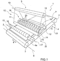
Figure 1 is a schematic perspective view, with parts removed for clarity, of a preferred embodiment of the sanding machine of the present invention; -
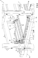
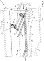
Figures 2 and3 are two schematic perspective views, with parts removed for clarity, of a detail of the sanding machine inFigure 1 ; -
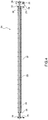
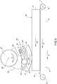
Figure 4 is a schematic side view, with parts in section and parts removed for clarity, of a detail inFigures 2 and3 ; and -
Figure 5 schematically illustrates the principle of operation of the detail inFigure 4 . - With reference to
Figure 1 ,number 1 indicates, as a whole, a sanding machine for sanding/finishing panels 2 made of wood, metal or the like, substantially parallelepiped in shape. - The
sanding machine 1 comprises a support frame 3 (Figures 2 and3 ) and afeeding device 4 mounted on theframe 3 for successively feeding thepanels 2 in ahorizontal direction 5. - The
device 4 comprises alower belt conveyor 6a, which has an upper transport branch defining a horizontal support plane P for thepanels 2, and is wound in a ring shape around a pair of motorizedpulleys 7 mounted so as to rotate, with respect to theframe 3, around respectivelongitudinal axes 8 parallel to each other and to ahorizontal direction 9 transverse todirection 5. - The
device 4 further comprises a plurality ofupper pressure rollers 6b kept in contact with thepanels 2 to hold thepanels 2 on the plane P. - The
sanding machine 1 further comprises asanding unit 10 comprising, in turn, anabrasive band 11, which is wound in a ring shape around a plurality of idler rollers 12 (in this case three rollers 12), and is fed around therollers 12 in a direction of rotation opposite to a direction of rotation of theconveyor 6a so as to cooperate with thedevice 4 to feed thepanels 2 indirection 5. - The
rollers 12 are mounted so as to rotate around respectivelongitudinal axes 13 parallel todirection 9, and are arranged so as to give the band 11 a substantially triangular configuration. - In particular, the arrangement of the
rollers 12 is such that theband 11 has a substantially flat,lower branch 14 parallel to the plane P. - The
sanding machine 1 is further provided with adetection device 15 mounted above and at the entrance of the plane P in order to detect a width of thepanel 2 indirection 9. - In this case, the
device 15 is a mechanical device comprising a plurality ofcontact rollers 16, which are distributed above the plane P indirection 9, and are mounted so as to rotate aroundrespective rotation axes 17 parallel todirection 9. - As a result of the forward movement of the
panel 2 indirection 5, therollers 16 arranged within the feeding path of thepanel 2 are lifted by thepanel 2 so as to allow thedevice 15 to detect the width of thepanel 2 indirection 9. - According to a variant, not shown, the
rollers 16 are removed and replaced with a detection device which is not in contact with thepanels 2, for example, an optical, inductive or capacitive detection device. - The
lower branch 14 of theband 11 is selectively brought into contact with anupper face 18 of thepanels 2 by athrust device 19 mounted inside theband 11. - In this case, the
device 19 comprises a plurality ofthrust elements 20, which are distributed inside theband 11 indirection 9, are mounted above thebranch 14, and are movable independently of each other in avertical direction 21 orthogonal todirections - Each
element 20 is movable indirection 21 between a lowered operating position, in which the corresponding portion of theband 11 is moved into contact with theface 18, and a raised rest position, in which the corresponding portion of theband 11 is disengaged from theface 18. - Each
panel 2 is fed by thedevice 4 indirection 5 from aninput station 22 to anoutput station 23 of themachine 1. - As shown in
Figures 2 ,3 and4 , theoutput station 23 is provided with abraking assembly 24 mounted above the plane P and comprising a pair ofcranks 25, which are mounted on opposite sides of theconveyor 6a indirection 9, and hinged to theframe 3 so as to rotate, with respect to theframe 3, around apivot axis 26 parallel todirection 9. - The
assembly 24 also comprises afirst transmission shaft 27 rotatably coupled to thecranks 25 so as to rotate, with respect to thecranks 25 and under the thrust of anactuator device 28, around theaxis 26. - The
device 28 comprises anelectric motor 29, which is fixed to theframe 3, and is connected to theshaft 27 through the interposition of areducer 30, in this case, a worm screw-worm wheel reducer. - The two
cranks 25 support, at their free ends, asecond transmission shaft 31, which is rotatably coupled to thecranks 25 through the interposition of respectiverolling bearings 32, and is mounted so as to rotate around arotation axis 33 parallel to theaxis 26. - The
shafts belt transmission 34 comprising abelt 35 wound in a ring around twopulleys 36 keyed to theshafts - Lastly, the
assembly 24 comprises acontact roller 37, which is fitted to theshaft 31 coaxially with theaxis 33, and is connected to theshaft 31 through the interposition of a pair offreewheels 38 mounted at the free ends of theroller 37. - With reference to
Figure 5 , eachfreewheel 38 comprises aninner ring 39 coupled in an angularly fixed manner to theshaft 31, anouter ring 40 coupled in an angularly fixed manner to theroller 37, and a plurality ofcoupling rollers 41 mounted between therings axis 33. - Each
roller 41 is mounted in aguide groove 42 formed between therings pin 43, which is slidably engaged in aguide hole 44 formed in thering 39, and is arranged between theroller 41 and aspring 45 housed in thehole 44. - The operation of the
braking assembly 24 will now be described starting from a moment when: - the
cranks 25 are rotated around theaxis 26 to move and keep theroller 37 in contact with theface 18 of thepanel 2; - the plane P of the
belt conveyor 6a is fed indirection 5 at a speed V1; and - the
transmission shaft 31 is fed around theaxis 33 at a peripheral speed V2 at least equal to the speed V1, preferably approximating the speed V1 by excess. - With regard to the foregoing, it should be pointed out that the electric motor 29:
- is adjusted during the tooling up of the
assembly 24 so that the speed V2 of theshaft 31 is greater than the maximum speed V1 of the plane P; or - is selectively controlled as a function of the speed V1 of the plane P, for example by means of an inverter connected to the
belt conveyor 6a, so that the speed V2 of theshaft 31 is always greater or at most equal to the speed V1. - At full capacity, due to the existing friction, the
panel 2 is fed indirection 5 at a speed V3 substantially equal to speed V1 and thecontact roller 37 is fed around theaxis 33 at a peripheral speed V4 substantially equal to speed V3 and, therefore, to speed V1. - Accordingly, since the speeds V1, V3, and V4 are at most equal to speed V2, the
coupling rollers 41 of thefreewheels 38 are moved against the action of thesprings 45, allowing theroller 37 to rotatably couple to theshaft 31. - When, in the event of malfunction, for example, of the
lower belt conveyor 6a and/or of the aforementionedupper pressure rollers 6b and/or of thesanding unit 10, the speed V3 of thepanel 2 at theoutput station 23 is greater than the speed V1 of the plane P of theconveyor 6a, and therefore the speed V4 of theroller 37 is greater than the speed V2 of theshaft 31, thecoupling rollers 41 are moved under the action of thesprings 45, allowing theroller 37 to couple in an angularly fixed manner to theshaft 31, therefore to rotate at speed V2, and to slow down thepanel 2 at theoutput station 23 to the same speed V2 as theshaft 31 and theroller 37. - Therefore, the
braking assembly 24 has some advantages mainly due to the fact that thefreewheels 38 ensure that thepanels 2 at theoutput station 23 always have a speed V3 which is, at most, equal to the speed V2 of thetransmission shaft 31.
Claims (10)
- A machine tool for the finishing of panels (2) comprising a feeding device (4), which defines a support plane (P) for at least one panel (2) and is designed to feed the panel (2) from an input station (22) to an output station (23) of the machine tool; and a finishing device (10), which is mounted between the input and output stations (22, 23) so as to carry out a finishing processing of the panel (2); and characterized in that it further comprises a braking assembly (24) to brake the panel (2) so that a feeding speed (V3) of the panel (2) through the output station (23) is, at the most, equal to a given threshold value (V2).
- The machine tool according to claim 1, wherein the braking assembly (24) is mounted in the area of the output station (23).
- The machine tool according to claim 1 or 2, wherein the feeding device (4) and the braking assembly (24) are arranged on opposite sides of the panel (2), in particular so as to engage a lower face and an upper face (18) of the panel (2).
- The machine tool according to any one of the preceding claims, wherein the feeding device (4) comprises a belt or roller conveyor (6a) defining the support plane (P), and the finishing device (10) comprises an abrasive band (11), which is mounted so as to rotate with a direction of rotation that is opposite to the direction of rotation of the belt or roller conveyor (6a).
- The machine tool according to any one of the preceding claims, wherein the braking assembly (24) comprises a contact roller (37), which is arranged in contact with an upper face (18) of the panel (2) and mounted so as to rotate around a rotation axis (33), which is transverse to a feeding direction (5) of the panel (2); a transmission shaft (31), which extends through the contact roller (37) and is mounted so as to rotate around the rotation axis (33); and coupling means (38) to angularly lock the transmission shaft (31) and the contact roller (37) to one another.
- The machine tool according to claim 5, wherein the coupling means (38) comprise at least one freewheel interposed between the transmission shaft (31) and the contact roller (37) and configured to angularly lock the transmission shaft (31) and the contact roller (37) to one another when the feeding speed (V3) of the panel (2) exceeds said threshold value (V2).
- The machine tool according to claim 5 or 6, wherein the braking assembly (24) further comprises actuator means (28) to move the transmission shaft (31) around the rotation axis (33).
- The machine tool according to claim 7, wherein the actuator means (28) comprise an electric motor (29) connected to the transmission shaft (31).
- The machine tool according to claim 8, wherein the actuator means (28) further comprise a control device to selectively control the operation of the electric motor (29) and, hence, a peripheral speed (V2) of the transmission shaft (31) depending on a feeding speed (V1) of the feeding device (4).
- The machine tool according to any one of the claims 5 to 9, wherein the assembly defined by the contact roller (37) and by the transmission shaft (31) is movable between a lowered operating position, in which the contact roller (37) is in contact with the panel (2), and a raised rest position, in which the contact roller (37) disengages the panel (2).
Applications Claiming Priority (1)
| Application Number | Priority Date | Filing Date | Title |
|---|---|---|---|
| IT102019000022965A IT201900022965A1 (en) | 2019-12-04 | 2019-12-04 | MACHINE TOOL FOR FINISHING PANELS |
Publications (2)
| Publication Number | Publication Date |
|---|---|
| EP3831530A1 true EP3831530A1 (en) | 2021-06-09 |
| EP3831530B1 EP3831530B1 (en) | 2024-07-17 |
Family
ID=70009231
Family Applications (1)
| Application Number | Title | Priority Date | Filing Date |
|---|---|---|---|
| EP20211691.9A Active EP3831530B1 (en) | 2019-12-04 | 2020-12-03 | Machine tool for the finishing of panels |
Country Status (2)
| Country | Link |
|---|---|
| EP (1) | EP3831530B1 (en) |
| IT (1) | IT201900022965A1 (en) |
Citations (3)
| Publication number | Priority date | Publication date | Assignee | Title |
|---|---|---|---|---|
| US3455066A (en) * | 1967-03-10 | 1969-07-15 | Barnes Drill Co | Feed rate control for abrading machines |
| US5720648A (en) * | 1995-08-03 | 1998-02-24 | Green; Gary L. | Feed rate controller for thickness sanding machine |
| EP3305467A1 (en) * | 2016-10-10 | 2018-04-11 | Viet Italia S.r.l. con Unico Socio | A sanding machine for sanding/finishing panels made of wood, metal or the like |
Family Cites Families (4)
| Publication number | Priority date | Publication date | Assignee | Title |
|---|---|---|---|---|
| US4621459A (en) * | 1984-04-23 | 1986-11-11 | Timesavers, Inc. | Segmented platen with diaphragm cylinder control |
| KR20040043391A (en) * | 2002-11-18 | 2004-05-24 | 주식회사 포스코 | Device for cleaning billy roll in strip grinder |
| CN2863357Y (en) * | 2005-12-01 | 2007-01-31 | 苏福马股份有限公司 | Abrasive band grinding attachment for breadth board |
| CN106425775B (en) * | 2016-12-06 | 2019-03-12 | 无锡昊康通用机械有限公司 | A kind of belt sander |
-
2019
- 2019-12-04 IT IT102019000022965A patent/IT201900022965A1/en unknown
-
2020
- 2020-12-03 EP EP20211691.9A patent/EP3831530B1/en active Active
Patent Citations (3)
| Publication number | Priority date | Publication date | Assignee | Title |
|---|---|---|---|---|
| US3455066A (en) * | 1967-03-10 | 1969-07-15 | Barnes Drill Co | Feed rate control for abrading machines |
| US5720648A (en) * | 1995-08-03 | 1998-02-24 | Green; Gary L. | Feed rate controller for thickness sanding machine |
| EP3305467A1 (en) * | 2016-10-10 | 2018-04-11 | Viet Italia S.r.l. con Unico Socio | A sanding machine for sanding/finishing panels made of wood, metal or the like |
Also Published As
| Publication number | Publication date |
|---|---|
| EP3831530B1 (en) | 2024-07-17 |
| IT201900022965A1 (en) | 2021-06-04 |
Similar Documents
| Publication | Publication Date | Title |
|---|---|---|
| CN204603996U (en) | A kind of modified lines double side polishing machine | |
| KR102472545B1 (en) | Conveyor system for battery activation process | |
| EP3831530B1 (en) | Machine tool for the finishing of panels | |
| CN220333786U (en) | High-speed tray lifting device | |
| CN112645000A (en) | High-speed turning belt conveyor line | |
| CN217200146U (en) | Roller platform is carried between two parties | |
| KR101576116B1 (en) | Improve the efficiency of movement conveying equipment by Subsidiary | |
| CN103057758A (en) | Heat blowing device of heat shrinkage film yardage roll packing machine | |
| CN112551108B (en) | Full-automatic robot setting system | |
| CN212668269U (en) | Power and free roller, conveying line structure with power and free roller and conveying vehicle | |
| US11878877B2 (en) | Material conveying device and material processing apparatus | |
| US8602207B2 (en) | Conveyor-belt linking apparatus of metallurgical furnace | |
| CN116873659B (en) | Cable conveying device | |
| EP4035830B1 (en) | Sanding machine for sanding/finishing panels made of wood, metal, plastic or the like | |
| CN209274767U (en) | An intelligent transport vehicle based on a two-way helical roller platform | |
| CN107399567B (en) | Trolley conveyor with lift function | |
| ITBO20000665A1 (en) | LINE FOR CONVEYING A WOODEN PANEL OR SIMILAR | |
| CN218538706U (en) | Turning type full-automatic tray conveying device | |
| IT201900001427A1 (en) | METHOD FOR GRINDING AND POLISHING GLASS SHEETS | |
| CN109532105B (en) | Transmission structure of paper bag arranging and finishing device | |
| KR101463838B1 (en) | Device for supplying grinded material of grinding machine | |
| CN102152205A (en) | Grinding machine | |
| CN116240669B (en) | A device for automatically adjusting the traction force of rollers in a flat knitting machine in sections | |
| CN113578755A (en) | Weight sorting equipment based on conveyer belt transportation | |
| CN221586811U (en) | Roller machine for conveying goods |
Legal Events
| Date | Code | Title | Description |
|---|---|---|---|
| PUAI | Public reference made under article 153(3) epc to a published international application that has entered the european phase |
Free format text: ORIGINAL CODE: 0009012 |
|
| STAA | Information on the status of an ep patent application or granted ep patent |
Free format text: STATUS: THE APPLICATION HAS BEEN PUBLISHED |
|
| AK | Designated contracting states |
Kind code of ref document: A1 Designated state(s): AL AT BE BG CH CY CZ DE DK EE ES FI FR GB GR HR HU IE IS IT LI LT LU LV MC MK MT NL NO PL PT RO RS SE SI SK SM TR |
|
| RAP1 | Party data changed (applicant data changed or rights of an application transferred) |
Owner name: BIESSE S.P.A. |
|
| STAA | Information on the status of an ep patent application or granted ep patent |
Free format text: STATUS: REQUEST FOR EXAMINATION WAS MADE |
|
| 17P | Request for examination filed |
Effective date: 20211209 |
|
| RBV | Designated contracting states (corrected) |
Designated state(s): AL AT BE BG CH CY CZ DE DK EE ES FI FR GB GR HR HU IE IS IT LI LT LU LV MC MK MT NL NO PL PT RO RS SE SI SK SM TR |
|
| STAA | Information on the status of an ep patent application or granted ep patent |
Free format text: STATUS: EXAMINATION IS IN PROGRESS |
|
| 17Q | First examination report despatched |
Effective date: 20230315 |
|
| 17Q | First examination report despatched |
Effective date: 20230420 |
|
| GRAP | Despatch of communication of intention to grant a patent |
Free format text: ORIGINAL CODE: EPIDOSNIGR1 |
|
| STAA | Information on the status of an ep patent application or granted ep patent |
Free format text: STATUS: GRANT OF PATENT IS INTENDED |
|
| INTG | Intention to grant announced |
Effective date: 20240213 |
|
| GRAS | Grant fee paid |
Free format text: ORIGINAL CODE: EPIDOSNIGR3 |
|
| P01 | Opt-out of the competence of the unified patent court (upc) registered |
Effective date: 20240506 |
|
| GRAA | (expected) grant |
Free format text: ORIGINAL CODE: 0009210 |
|
| STAA | Information on the status of an ep patent application or granted ep patent |
Free format text: STATUS: THE PATENT HAS BEEN GRANTED |
|
| AK | Designated contracting states |
Kind code of ref document: B1 Designated state(s): AL AT BE BG CH CY CZ DE DK EE ES FI FR GB GR HR HU IE IS IT LI LT LU LV MC MK MT NL NO PL PT RO RS SE SI SK SM TR |
|
| REG | Reference to a national code |
Ref country code: CH Ref legal event code: EP |
|
| REG | Reference to a national code |
Ref country code: DE Ref legal event code: R096 Ref document number: 602020034044 Country of ref document: DE |
|
| REG | Reference to a national code |
Ref country code: IE Ref legal event code: FG4D |
|
| REG | Reference to a national code |
Ref country code: LT Ref legal event code: MG9D |
|
| REG | Reference to a national code |
Ref country code: NL Ref legal event code: MP Effective date: 20240717 |
|
| PG25 | Lapsed in a contracting state [announced via postgrant information from national office to epo] |
Ref country code: PT Free format text: LAPSE BECAUSE OF FAILURE TO SUBMIT A TRANSLATION OF THE DESCRIPTION OR TO PAY THE FEE WITHIN THE PRESCRIBED TIME-LIMIT Effective date: 20241118 |
|
| REG | Reference to a national code |
Ref country code: AT Ref legal event code: MK05 Ref document number: 1703705 Country of ref document: AT Kind code of ref document: T Effective date: 20240717 |
|
| PG25 | Lapsed in a contracting state [announced via postgrant information from national office to epo] |
Ref country code: NL Free format text: LAPSE BECAUSE OF FAILURE TO SUBMIT A TRANSLATION OF THE DESCRIPTION OR TO PAY THE FEE WITHIN THE PRESCRIBED TIME-LIMIT Effective date: 20240717 |
|
| PG25 | Lapsed in a contracting state [announced via postgrant information from national office to epo] |
Ref country code: PT Free format text: LAPSE BECAUSE OF FAILURE TO SUBMIT A TRANSLATION OF THE DESCRIPTION OR TO PAY THE FEE WITHIN THE PRESCRIBED TIME-LIMIT Effective date: 20241118 Ref country code: NL Free format text: LAPSE BECAUSE OF FAILURE TO SUBMIT A TRANSLATION OF THE DESCRIPTION OR TO PAY THE FEE WITHIN THE PRESCRIBED TIME-LIMIT Effective date: 20240717 |
|
| PG25 | Lapsed in a contracting state [announced via postgrant information from national office to epo] |
Ref country code: NO Free format text: LAPSE BECAUSE OF FAILURE TO SUBMIT A TRANSLATION OF THE DESCRIPTION OR TO PAY THE FEE WITHIN THE PRESCRIBED TIME-LIMIT Effective date: 20241017 |
|
| PG25 | Lapsed in a contracting state [announced via postgrant information from national office to epo] |
Ref country code: GR Free format text: LAPSE BECAUSE OF FAILURE TO SUBMIT A TRANSLATION OF THE DESCRIPTION OR TO PAY THE FEE WITHIN THE PRESCRIBED TIME-LIMIT Effective date: 20241018 Ref country code: FI Free format text: LAPSE BECAUSE OF FAILURE TO SUBMIT A TRANSLATION OF THE DESCRIPTION OR TO PAY THE FEE WITHIN THE PRESCRIBED TIME-LIMIT Effective date: 20240717 Ref country code: PL Free format text: LAPSE BECAUSE OF FAILURE TO SUBMIT A TRANSLATION OF THE DESCRIPTION OR TO PAY THE FEE WITHIN THE PRESCRIBED TIME-LIMIT Effective date: 20240717 |
|
| PG25 | Lapsed in a contracting state [announced via postgrant information from national office to epo] |
Ref country code: BG Free format text: LAPSE BECAUSE OF FAILURE TO SUBMIT A TRANSLATION OF THE DESCRIPTION OR TO PAY THE FEE WITHIN THE PRESCRIBED TIME-LIMIT Effective date: 20240717 |
|
| PG25 | Lapsed in a contracting state [announced via postgrant information from national office to epo] |
Ref country code: LV Free format text: LAPSE BECAUSE OF FAILURE TO SUBMIT A TRANSLATION OF THE DESCRIPTION OR TO PAY THE FEE WITHIN THE PRESCRIBED TIME-LIMIT Effective date: 20240717 |
|
| PG25 | Lapsed in a contracting state [announced via postgrant information from national office to epo] |
Ref country code: AT Free format text: LAPSE BECAUSE OF FAILURE TO SUBMIT A TRANSLATION OF THE DESCRIPTION OR TO PAY THE FEE WITHIN THE PRESCRIBED TIME-LIMIT Effective date: 20240717 Ref country code: IS Free format text: LAPSE BECAUSE OF FAILURE TO SUBMIT A TRANSLATION OF THE DESCRIPTION OR TO PAY THE FEE WITHIN THE PRESCRIBED TIME-LIMIT Effective date: 20241117 |
|
| PG25 | Lapsed in a contracting state [announced via postgrant information from national office to epo] |
Ref country code: HR Free format text: LAPSE BECAUSE OF FAILURE TO SUBMIT A TRANSLATION OF THE DESCRIPTION OR TO PAY THE FEE WITHIN THE PRESCRIBED TIME-LIMIT Effective date: 20240717 |
|
| PG25 | Lapsed in a contracting state [announced via postgrant information from national office to epo] |
Ref country code: ES Free format text: LAPSE BECAUSE OF FAILURE TO SUBMIT A TRANSLATION OF THE DESCRIPTION OR TO PAY THE FEE WITHIN THE PRESCRIBED TIME-LIMIT Effective date: 20240717 Ref country code: RS Free format text: LAPSE BECAUSE OF FAILURE TO SUBMIT A TRANSLATION OF THE DESCRIPTION OR TO PAY THE FEE WITHIN THE PRESCRIBED TIME-LIMIT Effective date: 20241017 |
|
| PG25 | Lapsed in a contracting state [announced via postgrant information from national office to epo] |
Ref country code: RS Free format text: LAPSE BECAUSE OF FAILURE TO SUBMIT A TRANSLATION OF THE DESCRIPTION OR TO PAY THE FEE WITHIN THE PRESCRIBED TIME-LIMIT Effective date: 20241017 Ref country code: PL Free format text: LAPSE BECAUSE OF FAILURE TO SUBMIT A TRANSLATION OF THE DESCRIPTION OR TO PAY THE FEE WITHIN THE PRESCRIBED TIME-LIMIT Effective date: 20240717 Ref country code: NO Free format text: LAPSE BECAUSE OF FAILURE TO SUBMIT A TRANSLATION OF THE DESCRIPTION OR TO PAY THE FEE WITHIN THE PRESCRIBED TIME-LIMIT Effective date: 20241017 Ref country code: LV Free format text: LAPSE BECAUSE OF FAILURE TO SUBMIT A TRANSLATION OF THE DESCRIPTION OR TO PAY THE FEE WITHIN THE PRESCRIBED TIME-LIMIT Effective date: 20240717 Ref country code: IS Free format text: LAPSE BECAUSE OF FAILURE TO SUBMIT A TRANSLATION OF THE DESCRIPTION OR TO PAY THE FEE WITHIN THE PRESCRIBED TIME-LIMIT Effective date: 20241117 Ref country code: HR Free format text: LAPSE BECAUSE OF FAILURE TO SUBMIT A TRANSLATION OF THE DESCRIPTION OR TO PAY THE FEE WITHIN THE PRESCRIBED TIME-LIMIT Effective date: 20240717 Ref country code: GR Free format text: LAPSE BECAUSE OF FAILURE TO SUBMIT A TRANSLATION OF THE DESCRIPTION OR TO PAY THE FEE WITHIN THE PRESCRIBED TIME-LIMIT Effective date: 20241018 Ref country code: FI Free format text: LAPSE BECAUSE OF FAILURE TO SUBMIT A TRANSLATION OF THE DESCRIPTION OR TO PAY THE FEE WITHIN THE PRESCRIBED TIME-LIMIT Effective date: 20240717 Ref country code: ES Free format text: LAPSE BECAUSE OF FAILURE TO SUBMIT A TRANSLATION OF THE DESCRIPTION OR TO PAY THE FEE WITHIN THE PRESCRIBED TIME-LIMIT Effective date: 20240717 Ref country code: BG Free format text: LAPSE BECAUSE OF FAILURE TO SUBMIT A TRANSLATION OF THE DESCRIPTION OR TO PAY THE FEE WITHIN THE PRESCRIBED TIME-LIMIT Effective date: 20240717 Ref country code: AT Free format text: LAPSE BECAUSE OF FAILURE TO SUBMIT A TRANSLATION OF THE DESCRIPTION OR TO PAY THE FEE WITHIN THE PRESCRIBED TIME-LIMIT Effective date: 20240717 |
|
| PG25 | Lapsed in a contracting state [announced via postgrant information from national office to epo] |
Ref country code: SM Free format text: LAPSE BECAUSE OF FAILURE TO SUBMIT A TRANSLATION OF THE DESCRIPTION OR TO PAY THE FEE WITHIN THE PRESCRIBED TIME-LIMIT Effective date: 20240717 Ref country code: RO Free format text: LAPSE BECAUSE OF FAILURE TO SUBMIT A TRANSLATION OF THE DESCRIPTION OR TO PAY THE FEE WITHIN THE PRESCRIBED TIME-LIMIT Effective date: 20240717 Ref country code: DK Free format text: LAPSE BECAUSE OF FAILURE TO SUBMIT A TRANSLATION OF THE DESCRIPTION OR TO PAY THE FEE WITHIN THE PRESCRIBED TIME-LIMIT Effective date: 20240717 |
|
| REG | Reference to a national code |
Ref country code: DE Ref legal event code: R097 Ref document number: 602020034044 Country of ref document: DE |
|
| PG25 | Lapsed in a contracting state [announced via postgrant information from national office to epo] |
Ref country code: EE Free format text: LAPSE BECAUSE OF FAILURE TO SUBMIT A TRANSLATION OF THE DESCRIPTION OR TO PAY THE FEE WITHIN THE PRESCRIBED TIME-LIMIT Effective date: 20240717 |
|
| PG25 | Lapsed in a contracting state [announced via postgrant information from national office to epo] |
Ref country code: CZ Free format text: LAPSE BECAUSE OF FAILURE TO SUBMIT A TRANSLATION OF THE DESCRIPTION OR TO PAY THE FEE WITHIN THE PRESCRIBED TIME-LIMIT Effective date: 20240717 |
|
| PG25 | Lapsed in a contracting state [announced via postgrant information from national office to epo] |
Ref country code: SK Free format text: LAPSE BECAUSE OF FAILURE TO SUBMIT A TRANSLATION OF THE DESCRIPTION OR TO PAY THE FEE WITHIN THE PRESCRIBED TIME-LIMIT Effective date: 20240717 |
|
| PLBE | No opposition filed within time limit |
Free format text: ORIGINAL CODE: 0009261 |
|
| STAA | Information on the status of an ep patent application or granted ep patent |
Free format text: STATUS: NO OPPOSITION FILED WITHIN TIME LIMIT |
|
| 26N | No opposition filed |
Effective date: 20250422 |
|
| PG25 | Lapsed in a contracting state [announced via postgrant information from national office to epo] |
Ref country code: MC Free format text: LAPSE BECAUSE OF FAILURE TO SUBMIT A TRANSLATION OF THE DESCRIPTION OR TO PAY THE FEE WITHIN THE PRESCRIBED TIME-LIMIT Effective date: 20240717 |
|
| PG25 | Lapsed in a contracting state [announced via postgrant information from national office to epo] |
Ref country code: LU Free format text: LAPSE BECAUSE OF NON-PAYMENT OF DUE FEES Effective date: 20241203 |
|
| GBPC | Gb: european patent ceased through non-payment of renewal fee |
Effective date: 20241203 |
|
| PG25 | Lapsed in a contracting state [announced via postgrant information from national office to epo] |
Ref country code: SE Free format text: LAPSE BECAUSE OF FAILURE TO SUBMIT A TRANSLATION OF THE DESCRIPTION OR TO PAY THE FEE WITHIN THE PRESCRIBED TIME-LIMIT Effective date: 20240717 |
|
| REG | Reference to a national code |
Ref country code: BE Ref legal event code: MM Effective date: 20241231 |
|
| PG25 | Lapsed in a contracting state [announced via postgrant information from national office to epo] |
Ref country code: GB Free format text: LAPSE BECAUSE OF NON-PAYMENT OF DUE FEES Effective date: 20241203 Ref country code: BE Free format text: LAPSE BECAUSE OF NON-PAYMENT OF DUE FEES Effective date: 20241231 |
|
| PG25 | Lapsed in a contracting state [announced via postgrant information from national office to epo] |
Ref country code: FR Free format text: LAPSE BECAUSE OF NON-PAYMENT OF DUE FEES Effective date: 20241231 |
|
| PG25 | Lapsed in a contracting state [announced via postgrant information from national office to epo] |
Ref country code: IE Free format text: LAPSE BECAUSE OF NON-PAYMENT OF DUE FEES Effective date: 20241203 |
|
| REG | Reference to a national code |
Ref country code: CH Ref legal event code: U11 Free format text: ST27 STATUS EVENT CODE: U-0-0-U10-U11 (AS PROVIDED BY THE NATIONAL OFFICE) Effective date: 20260101 |
|
| PGFP | Annual fee paid to national office [announced via postgrant information from national office to epo] |
Ref country code: IT Payment date: 20251117 Year of fee payment: 6 |
|
| PG25 | Lapsed in a contracting state [announced via postgrant information from national office to epo] |
Ref country code: CY Free format text: LAPSE BECAUSE OF FAILURE TO SUBMIT A TRANSLATION OF THE DESCRIPTION OR TO PAY THE FEE WITHIN THE PRESCRIBED TIME-LIMIT; INVALID AB INITIO Effective date: 20201203 |
|
| PGFP | Annual fee paid to national office [announced via postgrant information from national office to epo] |
Ref country code: DE Payment date: 20251229 Year of fee payment: 6 |
|
| PGFP | Annual fee paid to national office [announced via postgrant information from national office to epo] |
Ref country code: CH Payment date: 20260101 Year of fee payment: 6 |