EP3830419B1 - Kältemittelverdichter - Google Patents
Kältemittelverdichter Download PDFInfo
- Publication number
- EP3830419B1 EP3830419B1 EP19753260.9A EP19753260A EP3830419B1 EP 3830419 B1 EP3830419 B1 EP 3830419B1 EP 19753260 A EP19753260 A EP 19753260A EP 3830419 B1 EP3830419 B1 EP 3830419B1
- Authority
- EP
- European Patent Office
- Prior art keywords
- drive
- compressor
- electric
- damper element
- refrigerant compressor
- Prior art date
- Legal status (The legal status is an assumption and is not a legal conclusion. Google has not performed a legal analysis and makes no representation as to the accuracy of the status listed.)
- Active
Links
Images

Classifications
-
- F—MECHANICAL ENGINEERING; LIGHTING; HEATING; WEAPONS; BLASTING
- F04—POSITIVE - DISPLACEMENT MACHINES FOR LIQUIDS; PUMPS FOR LIQUIDS OR ELASTIC FLUIDS
- F04C—ROTARY-PISTON, OR OSCILLATING-PISTON, POSITIVE-DISPLACEMENT MACHINES FOR LIQUIDS; ROTARY-PISTON, OR OSCILLATING-PISTON, POSITIVE-DISPLACEMENT PUMPS
- F04C18/00—Rotary-piston pumps specially adapted for elastic fluids
- F04C18/02—Rotary-piston pumps specially adapted for elastic fluids of arcuate-engagement type, i.e. with circular translatory movement of co-operating members, each member having the same number of teeth or tooth-equivalents
- F04C18/0207—Rotary-piston pumps specially adapted for elastic fluids of arcuate-engagement type, i.e. with circular translatory movement of co-operating members, each member having the same number of teeth or tooth-equivalents both members having co-operating elements in spiral form
- F04C18/0215—Rotary-piston pumps specially adapted for elastic fluids of arcuate-engagement type, i.e. with circular translatory movement of co-operating members, each member having the same number of teeth or tooth-equivalents both members having co-operating elements in spiral form where only one member is moving
-
- F—MECHANICAL ENGINEERING; LIGHTING; HEATING; WEAPONS; BLASTING
- F04—POSITIVE - DISPLACEMENT MACHINES FOR LIQUIDS; PUMPS FOR LIQUIDS OR ELASTIC FLUIDS
- F04C—ROTARY-PISTON, OR OSCILLATING-PISTON, POSITIVE-DISPLACEMENT MACHINES FOR LIQUIDS; ROTARY-PISTON, OR OSCILLATING-PISTON, POSITIVE-DISPLACEMENT PUMPS
- F04C2270/00—Control; Monitoring or safety arrangements
- F04C2270/12—Vibration
Definitions
- the invention relates to an electric refrigerant compressor, a method for compressing a refrigerant and a vehicle, in particular a motor vehicle, which comprises an electric refrigerant compressor.
- EP 2 500 517 A2 describes a scroll compressor for a vehicle.
- the compressor has a housing, a fixed scroll and a movable scroll, and a drive mechanism that drives the movable scroll, the drive mechanism having an eccentric pin to enable orbital movement of the movable scroll.
- US 2013/075209 A1 describes an electric compressor (e.g. for a vehicle cooling circuit).
- the compressor has a rotatable assembly, which includes an electric motor unit and a compressor unit, and which is rotatable about the central axis AX.
- DE 20 2016 008176 U1 relates to an electric motor, in particular for an electric refrigerant drive, with a motor housing in which a stator and a rotor rotatably mounted relative to it are accommodated.
- US 2014/271242 A1 describes a spiral pump with a sound-absorbing housing, a pump head, a pump motor and a cooling fan.
- US 2016/312780 A1 describes a compressor with an orbiting scroll element and a non-orbiting scroll element 142.
- the scroll elements cause a working fluid to be compressed into pockets as the pockets move from a radially outer position (e.g. at suction pressure) to a radially inner position (e.g (e.g. at outlet pressure).
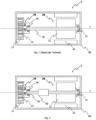
- FIG. 1 is a cross-sectional view of an electric scroll compressor 1 according to the prior art.
- the scroll compressor 1 comprises a compression unit 10, an electric drive 20, a drive shaft 30 and an orbiting drive 40 as well as a housing 60, which are arranged lying on a rotation axis I.
- the compression unit 10 comprises at least two spiral elements with spiral contours that are guided one into the other.
- stator spiral element 11 is fixedly arranged on the housing 60, while the other spiral element, the rotor spiral element 12, is positioned relative to the stator spiral element by the rotating electric drive 20, the drive shaft 30 and a special intermediate drive, the orbiting drive 40 orbiting movement is offset.
- An orbiting movement is to be understood here in particular as an eccentric, circular movement path in which a rotor spiral element does not rotate relative to a stator spiral element.
- the rotating electric drive 20 includes a rotor 21 and a stator 22, which is fixedly arranged on the housing 60.
- the crescent-shaped volumes enclosed between the spiral elements decrease in size the movement continues towards the center of the compressor. This allows a gaseous refrigerant that is introduced from the edge between the spiral elements to be compressed. The refrigerant compressed in this way is then pushed out as so-called hot gas via a check valve.
- torsional shocks and/or torsional vibrations arise.
- excitation of the rotor spiral element for first-order torsional vibrations dominates, since the compressor element is compressed once per revolution of the electric drive and hot gas is therefore expelled once.
- the arrangement described here is similar to a gimbal suspension, in which a refrigerant compressor is firmly arranged on the base section, so that oscillations and vibrations arising in the refrigerant compressor are only passed on to the environment in a reduced manner. This simply reduces the transmission of oscillations and vibrations. However, direct airborne sound radiation via the surface of the compressor housing, as described above, also occurs with the suspension described above.
- an electric refrigerant compressor which has an elastic retaining ring between the stator and the housing of the refrigerant compressor.
- the elastic retaining ring between the stator and the housing of the electric refrigerant compressor serves, on the one hand, to be able to position the stator, which is typically pressed directly into the housing, precisely axially and radially relative to the housing, and, on the other hand, to prevent noise and vibrations generated by the electric motor to reduce.
- a refrigerant compressor in which a balance weight is arranged on a drive shaft extension.
- the balancing weight compensates for the static imbalance caused by the orbiting drive, which converts rotation into an eccentric circular motion.
- torsional shocks and/or torsional vibrations that can arise from the compression operation of the refrigerant compressor are not reduced by the balancing weight described above.
- the process described above stimulates a rotational shock in the rotor spiral element of the compressor unit per revolution of the electric drive, which does not represent a purely sinusoidal excitation of the first order, but rather excites a variety of harmonic harmonics.
- this leads to a so-called order fan with a distance of one order, which can lead to a noticeable operating noise in the frequency range between 1kHz and 3kHz and in the speed range of the electric drive above 3000 rpm .
- This operating noise can have a harsh character due to modulation effects of the individual arrangements that are close together in the frequency range, which typically leads to complaints about the refrigerant compressor or the vehicle in which the refrigerant compressor was installed.
- the radiation of this operating noise which is characterized by the high-frequency order fan, occurs on the one hand as direct airborne sound radiation via the surface of the compressor housing itself.
- a dynamic force and acceleration excitation occurs from compressor mounts and downstream parts (electric motor of the vehicle drive, frame and body parts, etc.), which in turn radiate the excitation as airborne sound.
- the object is achieved in particular by an electric refrigerant compressor according to claim 1, a method for compressing a refrigerant according to claim 10 and a use of a refrigerant compressor according to claim 11.
- an electric refrigerant compressor namely a scroll compressor
- a compressor unit an electric drive, a drive shaft and an orbiting drive
- a rotary shock absorber element being arranged between the orbiting drive and the electric drive
- the rotary shock absorber element is configured to provide insulation and/or damping To cause rotational shocks, which arise from compression operation in the compressor unit and which affect the orbiting drive Drive shaft and / or transmitted via reaction torques into a stator spiral element of the compressor unit.
- the compressor unit has the stator spiral element and a rotor spiral element, wherein the stator spiral element is preferably arranged stationary in space and/or on a housing of the compressor unit and the rotor spiral element is movable in an orbiting movement relative to the stator spiral element.
- an orbiting movement is to be understood in particular as an eccentric, circular movement path in which the rotor spiral element does not rotate relative to the stator spiral element.
- the rotary shock absorber element which is arranged between the orbiting drive and the electric drive, makes it possible to insulate and/or dampen the amplitudes of torsional shocks and/or torsional vibrations that come about as a result of compressor operation of the compressor unit and which are otherwise transmitted via the obritating drive Drive shaft and / or would be transmitted via reaction torques to the stator spiral element of the compressor unit.
- the torsional shocks and/or torsional vibrations are preferably insulated and/or damped directly on the drive shaft, so that the amplitudes of the torsional shocks and/or torsional vibrations are reduced, which would otherwise be transmitted to the rotor of the electric drive and via a magnetic field to the stator and ultimately to the The housing of the refrigerant compressor is passed on.
- An arrangement between the orbiting drive and the electric drive is to be understood in particular as an arrangement on, on or within the orbiting drive(s) and/or on, on or within the drive shaft and/or an arrangement (at least partially) in one ( adjacent to the orbiting drive and drive shaft) to understand an intermediate area between the orbiting drive and drive shaft and / or an intermediate area between the drive shaft and electric drive.
- the rotary shock absorber element can adjoin (directly) the orbiting drive and/or be arranged (directly) on the electric drive.
- the rotary shock absorber element can be spaced from the orbiting drive and/or electric drive, for example by at least 1 cm, preferably at least by 5 cm.
- a rotary shock absorber element is to be understood in particular as an element whose material differs from materials used in the orbiting drive or drive shaft, in particular having a lower modulus of elasticity than at least one of the materials mentioned or all of the materials mentioned, and/or an element with a variable damping volume.
- the torsional shock absorber element can in particular have a lower torsional rigidity and/or higher torsional damping compared to the drive shaft.
- the drive shaft can be designed in two or more parts, with the rotary shock absorber element preferably being arranged at least partially between two parts of the drive shaft.
- rotary shock absorber element(s) In general, exactly one or two or more rotary shock absorber element(s) can be provided.
- the torsional shock absorber element is designed to dampen and/or prevent torsional shocks with frequencies that are greater than 100Hz, in particular greater than 1kHz or preferably in a frequency range between 100Hz and 7kHz, in particular between 1kHz and 3kHz dampen.
- the torsional shock damping element preferably has at least one damping volume, preferably with at least one opening through which flow can pass.
- the compressor unit is attached to a housing and one or more compressor damper elements is/are attached between the compressor unit and the housing. This also makes it possible to reduce torsional shocks and/or torsional vibrations that are transmitted to the housing through the stator spiral element.
- the electric drive is attached to a housing and/or one or more drive damper elements is/are attached between the stator of the electric drive and/or the shaft bearing and the housing.
- the electric drive and/or the stator of the electric drive and/or the stator spiral element and/or the orbiting drive are attached to a common intermediate frame, which is attached relative to the housing via one or more compressor damping element(s) and/or drive damper element(s).
- the intermediate frame makes it possible to almost eliminate the previously strongly suppressed torsional shocks and/or torsional vibrations.
- the rotary shock absorber element and/or the compressor damper element/s and/or drive damper element/s is/are at least partially made of an elastic material, preferably an elastomer, in particular synthetic or natural rubber material and/or is/are the rotary shock absorber element and/or the compressor damper element(s) and/or the drive damper element(s) are at least partially made of a metal, in particular a porous metal body, preferably a woven fabric, knitted fabric, knitted fabric, more preferably a, in particular pressed, metal felt.
- the materials used in this embodiment can reduce the production cost of the rotary shock absorber element.
- the rotary shock absorber element has one or more spring elements which are arranged in the circumferential direction of the rotary shock absorber element and/or one or more disc spring elements.
- rotary shock absorber element acts hydraulically and/or pneumatically and/or at least partially acts in the direction of rotation.
- the rotary shock absorber element can be designed as a dual-mass flywheel.
- the above-mentioned object is further achieved by a method for compressing a refrigerant, using the refrigerant compressor of the above type.
- the method for compressing a refrigerant includes insulation and / or damping of rotational shocks that arise from a compression operation of the refrigerant compressor and extend over the Orbiting drive on the drive shaft and/or via reaction moments transferred into the stator spiral element using a rotary shock absorber element arranged between an orbiting drive (40) and a drive shaft.
- the above object is further achieved by using a refrigerant compressor of the above type for a motor vehicle, in particular a hybrid or electric vehicle.
- the above-mentioned object is achieved by a motor vehicle, in particular a hybrid or electric vehicle, which includes a refrigerant compressor of the above type.
- FIG. 2 is a cross-sectional view of a first embodiment of the electric refrigerant compressor 1 according to the invention.
- the electric refrigerant compressor 1 shown is a scroll compressor and includes a compression unit 10, an electric drive 20, a drive shaft 30 and an orbiting drive 40 as well as a housing 60, which are arranged lying on a rotation axis I.
- the compression unit 10 comprises a stator spiral element 11, which is fixedly arranged on the housing 60, and a rotor spiral element 12, which is orbited relative to the stator spiral element by the rotating electric drive 20, the drive shaft 30 and the orbiting drive 40 Movement is offset.
- the rotating electric drive 20 includes a rotor 21 and a stator 22, which is fixedly arranged on the housing 60.
- a rotary shock absorber element 50 is arranged between the orbiting drive 40 and the electric drive 20 on or within the drive shaft 30.
- the torsional shock absorber 50 insulates and/or dampens torsional shocks and/or torsional vibrations that are transmitted to the stator spiral element 11 and from there directly to a housing 60 of the refrigerant compressor. Furthermore, the torsional shocks and/or torsional vibrations are reduced, which are transmitted via the rotor spiral element 12 to the orbiting drive 40 and from there to a drive shaft 30, which supplies the orbiting drive 40 with a rotational movement.
- the torsional shocks and/or torsional vibrations can be transmitted to the stator 22 of the electric drive 20 via reaction torques on bearings 31 of the drive shaft 30 or through a magnetic coupling between the rotor 21 and stator 22 of the rotating electric drive 20.
- the torsional shocks and/or torsional vibrations transmitted to the bearings 31 of the drive shaft and to the stator 22 of the electric drive 20 can lead to vibrations there, which are transmitted to the housing 60 of the refrigerant compressor 1.
- FIG. 3 a cross-sectional view of a further embodiment of the electric refrigerant compressor 1 is shown.
- the electric refrigerant compressor 1 shown is a scroll compressor, in which in addition to the in Fig. 2 illustrated embodiment, a compressor damper element 70 is arranged between the stator spiral element 11 of the compressor unit 10 and the housing 60.
- the compressor damper element 70 is at least substantially annular.
- a drive damper element 80 is arranged between the stator 22 of the electric drive 20 and the housing 60.
- several compressor damper elements 70 and several drive damper elements 80 would also be conceivable.
- Fig.4 shows a cross-sectional view of an embodiment of the torsional shock absorber element 50 according to the invention.
- torsional shocks and/or torsional oscillations which are passed on to the torsional shock absorber element 50 by the orbiting drive 40, are passed on to a torsional shock absorber receptacle 51.
- the rotary shock absorber holder 51 consists of a shaft section and a hollow shaft section, the shaft section having a smaller diameter than the hollow shaft section having.
- the rotary shock absorber element 50 has a rotary shock absorber part 52, which is firmly connected to the rotary shock absorber receptacle 51 on a first side and is arranged centrally in the hollow shaft section.
- the rotary shock absorber part 52 is firmly connected to a rotary shock absorber shaft 53.
- the rotary shock absorber shaft 53 extends into the hollow shaft section of the rotary shock absorber receptacle 51.
- several bearings 54 are arranged between the rotary shock absorber receptacle 51 and the rotary shock absorber shaft 53, which enable the rotary shock absorber receptacle 51 and the rotary shock absorber shaft 53 to be rotated against each other in the radial direction.
Landscapes
- Engineering & Computer Science (AREA)
- Mechanical Engineering (AREA)
- General Engineering & Computer Science (AREA)
- Applications Or Details Of Rotary Compressors (AREA)
- Rotary Pumps (AREA)
Description
- Die Erfindung betrifft einen elektrischen Kältemittelverdichter, ein Verfahren zum Verdichten eines Kältemittels sowie ein Fahrzeug, insbesondere Kraftfahrzeug, das einen elektrischen Kältemittelverdichter umfasst.
- In Kraftfahrzeugen werden neben riemengetriebenen Kältemittelverdichtern zunehmend elektrisch angetriebene Kältemittelverdichter verwendet. Insbesondere bei Hybrid- und Elektrofahrzeugen haben sich elektrisch angetriebene Kältemittelverdichter bewehrt.
- Oftmals sind elektrisch angetriebene Kältemittelverdichter, die in Kraftfahrzeugen verwendet werden, als sogenannte Scrollverdichter ausgeführt.
-
EP 2 500 517 A2 beschreibt einen Scroll-Kompressor für ein Fahrzeug. Der Kompressor hat ein Gehäuse, eine feste Spirale und eine bewegliche Spirale und einen Antriebsmechanismus, der die bewegliche Spirale antreibt, wobei der Antriebsmechanismus einen exzentrischen Stift aufweist, um eine Umlaufbewegung der beweglichen Spirale zu ermöglichen. -
US 2013/075209 A1 beschreibt einen elektrischen Kompressor (z.B. für einen Kühlkreislauf eines Fahrzeugs). Der Kompressor weist eine drehbare Anordnung auf, die eine elektrische Motoreinheit und eine Verdichtereinheit umfasst, und die um die zentrale Achse AX drehbar ist. -
DE 20 2016 008176 U1 betrifft einen Elektromotor, insbesondere für einen elektrischen Kältemittelantrieb, mit einem Motorgehäuse, in welchem ein Stator sowie ein gegenüber diesem drehbar gelagerter Rotor aufgenommen sind. -
US 2014/271242 A1 beschreibt eine Spiralpumpe mit einem schalldämpfenden Gehäuse, einem Pumpenkopf, einem Pumpenmotor und einem Kühlgebläse. -
US 2016/312780 A1 beschreibt einen Kompressor mit einem umlaufenden Spiralelement und einem nicht umlaufenden Spiralelement 142. Die Spiralelemente bewirken, dass ein Arbeitsfluid in Taschen komprimiert wird, wenn sich die Taschen von einer radial äußeren Position (z. B. bei Ansaugdruck) zu einer radial inneren Position (z. B. bei Auslassdruck) bewegen. - In
Fig. 1 ist eine Querschnittsansicht eines elektrischen Scrollverdichters 1 gemäß dem Stand der Technik abgebildet. Der Scrollverdichter 1 umfasst eine Verdichtungseinheit 10, einen elektrischen Antrieb 20, eine Antriebswelle 30 und einen Orbitierungsantrieb 40 sowie ein Gehäuse 60, die auf einer Rotationsachse I liegend angeordnet sind. Die Verdichtungseinheit 10 umfasst mindestens zwei ineinander geführte Spiralelemente mit Spiralkonturen. - Eines dieser Spiralelemente, das Statorspiralelement 11, ist an dem Gehäuse 60 fest angeordnet, während das andere Spiralelement, das Rotorspiralelement 12, durch den rotierenden elektrischen Antrieb 20, der Antriebswelle 30 und einen speziellen Zwischentrieb, dem Orbitierungsantrieb 40, relativ zu dem Statorspiralelement in eine orbitierende Bewegung versetzt wird.
- Unter einer orbitierenden Bewegung ist hierbei insbesondere eine exzentrische, kreisförmige Bewegungsbahn zu verstehen, bei der ein/das Rotorspiralelement gegenüber einem/dem Statorspiralelement nicht rotiert.
- Der rotierende elektrische Antrieb 20 umfasst einen Rotor 21 sowie einen Stator 22, der an dem Gehäuse 60 fest angeordnet ist. Die zwischen den Spiralelementen eingeschlossenen sichelförmigen Volumina verkleinern sich durch den Bewegungsablauf zur Mitte des Verdichters hin immer weiter. Dadurch kann ein gasförmiges Kältemittel, das vom Rand zwischen die Spiralelemente eingebracht wird, verdichtet werden. Das so komprimierte Kältemittel wird dann als sogenanntes Heißgas über ein Rückschlagventil ausgeschoben.
- Durch ein Durchlaufen eines Kreisprozesses während der Verdichtung des Kältemittels sowie durch Öffnungs- und Schließvorgängen des Rückschlagventils entstehen unter anderem Drehstöße und/oder Drehschwingungen. Insbesondere beim elektrisch angetriebenen Kältemittelverdichter mit Scrollverdichter dominiert eine Anregung des Rotorspiralelements für Drehschwingungen erster Ordnung, da pro Umdrehung des elektrischen Antriebs das Verdichterelement einmal verdichtet und somit einmal Heißgas ausgeschoben wird.
- Im bisherigen Stand der Technik werden einerseits spezielle Aufhängungen bzw. Halterungen der Kaltemittelverdichter verwendet, um das Weiterleiten von Vibrationen des Kaltemittelverdichter an weitere Komponenten zu verhindern. Beispielsweise wird in
US 2013 075 209 A eine Aufhängung beschrieben, die einen Grundabschnitt aufweist, der durch elastische Verbindungselemente mit einem ersten Rahmenteil verbunden ist, wobei das erste Rahmenteil durch weitere elastische Verbindungselemente mit einem zweiten Rahmenteil verbunden ist. - Die hier beschriebene Anordnung ähnelt einer kardanischen Aufhängung, bei der ein Kältemittelverdichter fest auf dem Grundabschnitt angeordnet ist, so dass im Kältemittelverdichter entstehende Schwingungen und Vibrationen nur reduziert an die Umgebung weitergeleitet werden. Hierdurch wird lediglich eine Weiterleitung von Schwingungen und Vibrationen reduziert. Eine direkte Luftschallabstrahlung über die Oberfläche des Verdichtergehäuses, wie oben beschrieben, erfolgt jedoch auch mit der oben beschriebenen Aufhängung.
- In
CH 2 975 555 A - Aus
US 2012 183 422 A ist ein elektrischer Kältemittelverdichter bekannt, der einen elastischen Haltering zwischen Stator und dem Gehäuse des Kältemittelverdichters aufweist. Der elastische Haltering zwischen Stator und dem Gehäuse des elektrischen Kältemittelverdichters dient dazu, einerseits den Stator, der typischerweise direkt in das Gehäuse eingepresst wird, gegenüber den Gehäuse präzise axial und radial positionieren zu können, und andererseits Geräusche und Vibrationen, die durch den Elektromotor erzeugt werden zu reduzieren. - In
WO 2017 108 574 A1 wird beispielsweise ein Kältemittelverdichter offenbart, bei dem ein Ausgleichsgewicht an einem Antriebswellenfortsatz angeordnet ist. Das Ausgleichsgewicht gleicht die statische Unwucht aus, die durch den Orbitierungsantrieb entsteht, der eine Rotation in eine exzentrische Kreisbewegung umwandelt. Drehstöße und/oder Drehschwingungen, die durch den Verdichtungsbetrieb des Kältemittelverdichters entstehen können, werden durch das oben beschriebene Ausgleichsgewicht hingegen nicht reduziert. - Der oben beschriebene Vorgang regt pro Umdrehung des elektrischen Antriebs einen Drehstoß im Rotorspiralelement der Verdichtereinheit an, der keine rein sinusförmige Anregung der ersten Ordnung darstellt, sondern vielfältige harmonische Oberwellen anregt. Typischerweise führt dies zu einem sogenannten Ordnungsfächer mit dem Abstand einer Ordnung, der im Frequenzbereich zwischen 1kHz und 3kHz sowie im Drehzahlbereich des elektrischen Antriebs oberhalb 3000 min-1 zu einem auffälligen Betriebsgeräusch führen kann. Dieses Betriebsgeräusch kann durch Modulationseffekte der im Frequenzbereich dicht beieinanderliegenden Einzelanordnungen einen grellen Charakter aufweisen, der typischerweise zu Beanstandungen des Kältemittelverdichters bzw. des Fahrzeuges, in welchem der Kältemittelverdichter verbaut wurde, führt. Die Abstrahlung dieses vom hochfrequenten Ordnungsfächer geprägten Betriebsgeräusches erfolgt einerseits als direkte Luftschallabstrahlung über die Oberfläche des Verdichtergehäuses selbst.
- Zusätzlich erfolgt eine dynamische Kraft- und Beschleunigungsanregung von Verdichter-Halterungen sowie nachgelagerter Teile (Elektromotor des Fahrzeugantriebs, Rahmen- und Karosserieteile etc.), die die Anregung ihrerseits als Luftschall abstrahlen.
- Aus dem bisherigen Stand der Technik wird ersichtlich, dass weiterhin keine zufriedenstellende technische Lösung für die oben beschriebenen Nachteile vorhanden ist. Es ist daher Aufgabe der Erfindung, einen vergleichsweise einfachen elektrisch angetriebenen Kältemittelverdichter bereitzustellen, der zu möglichst geringen Beeinträchtigungen in der Anwendung führt.
- Die Aufgabe wird insbesondere durch einen elektrischen Kältemittelverdichter nach Anspruch 1, ein Verfahren zum Verdichten eines Kältemittels nach Anspruch 10 sowie eine Verwendung eines Kältemittelverdichters nach Anspruch 11 gelöst.
- Die Aufgabe wird insbesondere durch einen elektrischen Kältemittelverdichter, und zwar durch einen Scrollverdichter, gelöst, aufweisend:
- eine Verdichtereinheit mit einem Statorspiralelement und einem Rotorspiralelement, das in einer orbitierenden Bewegung gegenüber dem Statorspiralelement bewegbar ist;
- einen elektrischen Antrieb zum Erzeugen einer Drehbewegung;
- eine Antriebswelle zum Aufnehmen und Weiterleiten der Drehbewegung des elektrischen Antriebs;
- einen Orbitierungsantrieb der konfiguriert ist, die Drehbewegung durch die Antriebswelle zu empfangen, die Drehbewegung in eine orbitierende Bewegung gegenüber dem Statorspiralelement umzuwandeln und die orbitierende Bewegung an das Rotorspiralelement weiterzugeben;
- Gemäß einem Kerngedanken der Erfindung wird die Aufgabe durch einen elektrischen Kältemittelverdichter, und zwar durch einen Scrollverdichter, mit einer Verdichtereinheit, einem elektrischen Antrieb, einer Antriebswelle und einem Orbitierungsantrieb gelöst, wobei zwischen dem Orbitierungsantrieb und dem elektrischen Antrieb ein Drehstoßdämpferelement angeordnet ist, wobei das Drehstoßdämpferelement konfiguriert ist, eine Dämmung und/oder Dämpfung von Drehstößen zu bewirken, die durch einen Verdichtungsbetrieb in der Verdichtereinheit entstehen und sich über den Orbitierungsantrieb auf die Antriebswelle und/oder sich über Reaktionsmomente in ein Statorspiralelement der Verdichtereinheit übertragen. Insbesondere weist die Verdichtereinheit das Statorspiralelement und ein Rotorspiralelement auf, wobei das Statorspiralelement vorzugsweise feststehend im Raum und/oder an einem Gehäuse der Verdichtereinheit angeordnet ist und das Rotorspiralelement in einer orbitierenden Bewegung gegenüber dem Statorspiralelement bewegbar ist. Wie bereits erwähnt ist unter einer orbitierenden Bewegung insbesondere eine exzentrische, kreisförmige Bewegungsbahn zu verstehen, bei der das Rotorspiralelement gegenüber dem Statorspiralelement nicht rotiert. Durch das Drehstoßdämpferelement, dass zwischen dem Orbitierungsantrieb und dem elektrischen Antrieb angeordnet ist, wird es ermöglicht die Amplituden von Drehstößen und/oder Drehschwingungen zu dämmen und/oder dämpfen, die durch einen Verdichterbetrieb der Verdichtereinheit zustande kommen und die sich ansonsten über den Obritierungsantrieb auf die Antriebswelle und/oder sich über Reaktionsmomente auf das Statorspiralelement der Verdichtereinheit übertragen würden. Die Drehstöße und/oder Drehschwingungen werden vorzugsweise direkt auf der Antriebswelle gedämmt und/oder gedämpft, sodass die Amplituden der Drehstöße und/oder Drehschwingungen reduziert werden, die sich ansonsten an den Rotor des elektrischen Antriebs und über ein Magnetfeld an den Stator und letztlich an das Gehäuse des Kältemittelverdichters weitergegeben werden.
- Unter einer Anordnung zwischen dem Orbitierungsantrieb und dem elektrischen Antrieb ist insbesondere eine Anordnung auf dem, an dem oder innerhalb des Orbitierungsantrieb(es) und/oder auf, an oder innerhalb der Antriebswelle zu verstehen und/oder eine Anordnung (zumindest teilweise) in einem (an Orbitierungsantrieb und Antriebswelle angrenzenden) Zwischenbereich zwischen Orbitierungsantrieb und Antriebswelle und/oder einem Zwischenbereich zwischen Antriebswelle und elektrischem Antrieb zu verstehen. Ggf. kann das Drehstoßdämpferelement (direkt) an den Orbitierungsantrieb angrenzen und/oder (direkt) an dem elektrischen Antrieb angeordnet sein. Alternativ kann das Drehstoßdämpferelement von Orbitierungsantrieb und/oder elektrischen Antrieb beabstandet sein, beispielsweise um mindestens 1 cm, vorzugsweise mindestens um 5 cm.
- Unter einem Drehstoßdämpferelement ist insbesondere ein Element zu verstehen, dessen Material sich von in Orbitierungsantrieb bzw. Antriebswelle verwendeten Materialien unterscheidet, insbesondere einen geringeren E-Modul aufweist als zumindest einer der genannten Materialien oder als sämtliche der genannten Materialien, und/oder ein Element mit einem veränderbaren Dämpfungsvolumen. Das Drehstoßdämpferelement kann insbesondere eine geringere Drehsteifigkeit und/oder höhere Drehdämpfung im Vergleich zu der Antriebswelle aufweisen.
- Ausführungsgemäß kann die Antriebswelle zwei- oder mehrteilig ausgebildet sein, wobei das Drehstoßdämpferelement vorzugsweis zumindest teilweise zwischen zwei Teilen der Antriebswelle angeordnet ist.
- Im Allgemeinen kann genau ein oder es können zwei oder mehr Drehstoßdämpferelement(e) vorgesehen sein.
- In einer bevorzugten Ausführungsform der Erfindung ist das Drehstoßdämpferelement dazu ausgelegt, Drehstöße mit Frequenzen, die größer als 100Hz sind, insbesondere größer als 1kHz oder vorzugsweise in einem Frequenzbereich zwischen 100Hz und 7kHz, insbesondere zwischen 1kHz und 3kHz, liegen, zu dämmen und/oder zu dämpfen. Durch das Dämmen und/oder Dämpfen von Drehstößen mit obigen Frequenzen werden insbesondere auffällige Betriebsgeräusche reduziert, die einen grellen Klangcharakter aufweisen und letztlich zu Beanstandungen des Fahrzeuggeräuschs führt.
- Vorzugsweise weist das Drehstoßdämpfungselement mindestens ein Dämpfungsvolumen, vorzugsweise mit mindestens einer durchströmbaren Öffnung auf.
- Vorzugsweise ist die Verdichtereinheit an einem Gehäuse angebracht und zwischen der Verdichtereinheit und dem Gehäuse ist/sind ein oder mehrere Verdichterdämpferelement/e angebracht. Dadurch können auch Drehstöße und/oder Drehschwingungen, die durch das Statorspiralelement an das Gehäuse übertragen werden reduziert werden.
- Ausführungsgemäß ist der elektrische Antrieb an einem Gehäuse angebracht und/oder ist/sind zwischen Stator des elektrischen Antriebs und/oder der Wellenlagerung und dem Gehäuse ein oder mehrere Antriebsdämpferelement/e angebracht. Dadurch können die bereits reduzierten Drehstöße und/oder Drehschwingungen, die weiterhin an dem Stator des elektrischen Antriebs ankommen könnten, weiter reduziert werden, so dass diese weniger Vibrationen an das Gehäuse übertragen.
- Vorzugsweise sind der elektrische Antrieb und/oder der Stator des elektrischen Antriebs und/oder das Statorspiralelement und/oder der Orbitierungsantrieb an einem gemeinsamen Zwischenrahmen angebracht, der gegenüber dem Gehäuse über ein oder mehrere Verdichterdämpfungselement/e und/oder Antriebsdämpferelement/e angebracht ist. Durch den Zwischenrahmen wird es ermöglicht, die bisher stark unterdrückten Drehstöße und/oder Drehschwingungen annähernd zu eliminieren.
- In einer weiteren bevorzugten Ausführungsform der Erfindung ist/sind das Drehstoßdämpferelement und/oder das/die Verdichterdämpferelement/e und/oder Antriebsdämpferelement/e zumindest teilweise aus einem elastischen Material, vorzugsweise einem Elastomer, insbesondere Synthese- oder Naturkautschukmaterial hergestellt und/oder ist/sind das Drehstoßdämpferelement und/oder das/die Verdichterdämpferelement/e und/oder das/die Antriebsdämpferelement/e zumindest teilweise aus einem Metall, insbesondere einem porösen Metallkörper, vorzugsweise einem Gewebe, Gestrick, Gewirk, weiter vorzugsweise einem, insbesondere gepressten, Metallfilz hergestellt. Durch die in dieser Ausführungsform verwendeten Materialien können die Produktionskosten des Drehstoßdämpferelements reduziert werden.
- Alternativ weist das Drehstoßdämpferelement ein oder mehrere Federelement/e auf, das/die in Umfangsrichtung des Drehstoßdämpferelements angeordnet ist/sind, und/oder ein oder mehrere Tellerfederelement/e auf.
- Ebenfalls denkbar ist eine Ausführungsform, bei der das Drehstoßdämpferelement hydraulisch und/oder pneumatisch wirkt und/oder zumindest teilweise in Drehrichtung wirkt.
- Des Weiteren kann das Drehstoßdämpferelement als ein Zweimasseschwungrad ausgeführt sein.
- Die oben genannte Aufgabe wird weiterhin gelöst durch ein Verfahren zum Verdichten eines Kältemittels, unter Verwendung des Kältemittelverdichters der obigen Art. Das Verfahren zum Verdichten eines Kältemittels umfasst eine Dämmung und/oder Dämpfung von Drehstößen, die durch einen Verdichtungsbetrieb des Kältemittelverdichters enstehen und sich über den Orbitierungsantrieb auf die Antriebswelle und/oder sich über Reaktionsmomente in das Statorspiralelement übertragen, unter Verwendung eines ein Drehstoßdämpferelement, das zwischen einem Orbitierungsantrieb (40) und einer Antriebswelle angeordnet ist.
- Die obige Aufgabe wird weiterhin gelöst durch die Verwendung eines Kältemittelverdichters nach obiger Art für ein Kraftfahrzeug, insbesondere ein Hybrid oder Elektrofahrzeug.
- Insbesondere wird die oben genannte Aufgabe durch ein Kraftfahrzeug, insbesondere ein Hybrid oder Elektrofahrzeug, gelöst, das einen Kältemittelverdichter nach obiger Art umfasst.
- Weitere Ausführungsformen ergeben sich aus den Unteransprüchen.
- Nachfolgend wird die Erfindung anhand von Ausführungsbeispielen beschrieben, die anhand der Abbildungen näher erläutert werden. Hierbei zeigt:
- Fig. 1
- eine Querschnittsansicht eines elektrischen Kältemittelverdichters gemäß dem Stand der Technik;
- Fig. 2
- eine Querschnittsansicht einer ersten Ausführungsform des erfindungsgemäßen elektrischen Kältemittelverdichters;
- Fig. 3
- eine Querschnittsansicht einer weiteren Ausführungsform des erfindungsgemäßen elektrischen Kältemittelverdichters; und
- Fig. 4
- eine Querschnittsansicht einer weiteren Ausführungsform des erfindungsgemäßen Drehstoßdämpferelements;
- In
Fig. 2 ist eine Querschnittansicht einer ersten Ausführungsform des erfindungsgemäßen, elektrischen Kältemittelverdichters 1 abgebildet. Der abgebildete, elektrische Kältemittelverdichters 1 ist ein Scrollverdichter und umfasst eine Verdichtungseinheit 10, einen elektrischen Antrieb 20 eine Antriebswelle 30 und einen Orbitierungsantrieb 40 sowie ein Gehäuse 60, die auf einer Rotationsachse I liegend angeordnet sind. - Die Verdichtungseinheit 10 umfasst ein Statorspiralelement 11, das an dem Gehäuse 60 fest angeordnet ist, und ein Rotorspiralelement 12, das durch den rotierenden elektrischen Antrieb 20, die Antriebswelle 30 und den Orbitierungsantrieb 40, relativ zu dem Statorspiralelement in eine orbitierende Bewegung versetzt wird. Der rotierende elektrische Antrieb 20 umfasst einen Rotor 21 sowie einen Stator 22, der an dem Gehäuse 60 fest angeordnet ist.
- Des Weiteren ist ein Drehstoßdämpferelement 50 zwischen dem Orbitierungsantrieb 40 und dem elektrischen Antrieb 20 auf bzw. innerhalb der Antriebswelle 30 angeordnet. Der Drehstoßdämpfer 50 dämmt und/oder dämpft Drehstöße und/oder Drehschwingungen, die sich auf das Statorspiralelement 11 und von dort direkt auf ein Gehäuse 60 des Kältemittelverdichters übertragen. Des Weiteren werden die Drehstöße und/oder Drehschwingungen reduziert, die sich über das Rotorspiralelement 12 auf den Orbitierungsantrieb 40 und von dort auf eine Antriebswelle 30 übertragen, die den Orbitierungsantrieb 40 eine Rotationsbewegung zuführt. Von der Antriebswelle 30 können die Drehstöße und/oder Drehschwingungen über Reaktionsmomente auf Lager 31 der Antriebswelle 30 oder durch eine magnetische Kopplung zwischen Rotor 21 und Stator 22 des rotierenden, elektrischen Antriebs 20 auf den Stator 22 des elektrischen Antriebs 20 übertragen werden. Die auf die Lager 31 der Antriebswelle und auf den Stator 22 des elektrischen Antriebs 20 übertragenen Drehstöße und/oder Drehschwingungen können dort zu Vibrationen führen, die sich auf das Gehäuse 60 des Kältemittelverdichters 1 übertragen.
- In
Fig. 3 ist eine Querschnittansicht einer weiteren Ausführungsform des elektrischen Kältemittelverdichters 1 abgebildet. Der abgebildete, elektrischen Kältemittelverdichters 1 ist ein Scrollverdichter, bei der zusätzlich zu der inFig. 2 dargestellten Ausführungsform ein Verdichterdämpferelement 70 zwischen dem Statorspiralelement 11 der Verdichtereinheit 10 und dem Gehäuse 60 angeordnet ist. Das Verdichterdämpferelement 70 ist zumindest im Wesentlichen ringförmig ausgebildet. Des Weiteren ist ein Antriebsdämpferelement 80 zwischen Stator 22 des elektrischen Antriebs 20 und dem Gehäuse 60 angeordnet. Insbesondere wären auch mehrere Verdichterdämpferelemente 70 sowie mehrere Antriebsdämpferelemente 80 denkbar. -
Fig.4 zeigt eine Querschnittsansicht einer Ausführungsform des erfindungsgemäßen Drehstoßdämpferelements 50. In dieser Ausführungsform werden Drehstöße und/oder Drehschwingen, die von dem Orbitierungsantrieb 40 an das Drehstoßdämpferelement 50 weitergeleitet werden, an eine Drehstoßdämpferaufnahme 51 weitergeleitet. Die Drehstoßdämpferaufnahme 51 besteht aus einem Wellenabschnitt und einem Hohlwellenabschnitt, wobei der Wellenabschnitt einen geringeren Durchmesser als der Hohlwellenabschnitt aufweist. Ferner weist das Drehstoßdämpferelement 50 ein Drehstoßdämpferteil 52 auf, das auf einer ersten Seite fest mit der Drehstoßdämpferaufnahme 51 verbunden ist und zentrisch im Hohlwellenabschnitt angeordnet ist. Auf einer zweiten Seite, die gegenüber der ersten Seite angeordnet ist, ist der Drehstoßdämpferteil 52 fest mit einer Drehstoßdämpferwelle 53 verbunden. Die Drehstoßdämpferwelle 53 erstreckt sich dabei in den Hohlwellenabschnitt der Drehstoßdämpferaufnahme 51. Entlang des Umfangs der Drehstoßdämpferwelle 53 sind zwischen Drehstoßdämpferaufnahme 51 und Drehstoßdämpferwelle 53 mehrere Lager 54 angeordnet, die es ermöglichen, dass die Drehstoßdämpferaufnahme 51 und Drehstoßdämpferwelle 53 gegeneinander in radialer Richtung verdreht werden können. -
- 1
- elektrischer Kältemittelverdichter (Scrollverdichter)
- 10
- Verdichtereinheit
- 11
- Statorspiralelement
- 12
- Rotorspiralelement
- 20
- elektrischer Antrieb
- 21
- Rotor des elektrischen Antriebs
- 22
- Stator des elektrischen Antriebs
- 30
- Antriebswelle
- 40
- Orbitierungsantrieb
- 50
- Drehstoßdämpferelement
- 51
- Drehstoßdämpferaufnahme
- 52
- Drehstoßdämpferteil
- 53
- Drehstoßdämpferwelle
- 54
- Lager (Wälzlager)
- 60
- Gehäuse
- 70
- Verdichterdämpferelement
- 80
- Antriebsdämpferelement
- I
- Rotationsachse
Claims (12)
- Elektrischer Kältemittelverdichter (1), und zwar Scrollverdichter, aufweisend:- eine Verdichtereinheit (10) mit einem Statorspiralelement (11) und einem Rotorspiralelement (12), das in einer orbitierenden Bewegung gegenüber dem Statorspiralelement (11) bewegbar ist;- einen elektrischen Antrieb (20) zum Erzeugen einer Drehbewegung;- eine Antriebswelle (30) zum Aufnehmen und Weiterleiten der Drehbewegung des elektrischen Antriebs (20);- einen Orbitierungsantrieb (40) der konfiguriert ist, die Drehbewegung durch die Antriebswelle (30) zu empfangen, die Drehbewegung in eine orbitierende Bewegung gegenüber dem Statorspiralelement (11) umzuwandeln und die orbitierende Bewegung an das Rotorspiralelement (12) weiterzugeben;dadurch gekennzeichnet, dass zwischen dem Orbitierungsantrieb (40) und dem elektrischen Antrieb (20), insbesondere auf, an und/oder innerhalb der Antriebswelle (30), ein Drehstoßdämpferelement (50) angeordnet ist, wobei das Drehstoßdämpferelement (50) konfiguriert ist, eine Dämmung und/oder Dämpfung von Drehstößen zu bewirken, die durch einen Verdichtungsbetrieb in der Verdichtereinheit (10) entstehen und sich über den Orbitierungsantrieb (40) auf die Antriebswelle (30) und/oder sich über Reaktionsmomente in das Statorspiralelement (11) übertragen.
- Elektrischer Kältemittelverdichter (1) nach Anspruch 1,
wobei das Drehstoßdämpferelement (50) dazu ausgelegt ist, Drehstöße mit Frequenzen, die größer als 100Hz sind, insbesondere größer als 1kHz oder vorzugsweise in einem Frequenzbereich zwischen 100Hz und 7kHz, insbesondere zwischen 1kHz und 3kHz, liegen, zu dämmen und/oder zu dämpfen. - Elektrischer Kältemittelverdichter (1) nach einem der vorhergehenden Ansprüche,
wobei die Verdichtereinheit (10) an einem Gehäuse (60) angebracht ist und zwischen der Verdichtereinheit (10) und dem Gehäuse (60) ein oder mehrere Verdichterdämpferelement/e (70) angebracht ist/sind. - Elektrischer Kältemittelverdichter (1) nach einem der vorhergehenden Ansprüche,
wobei der elektrische Antrieb (20) an einem Gehäuse (60) angebracht ist und/oder zwischen Stator (22) des elektrischen Antriebs (20) und/oder der Wellenlagerung und dem Gehäuse (60) ein oder mehrere Antriebsdämpferelement/e (80) angebracht ist/sind. - Elektrischer Kältemittelverdichter (1) nach einem der vorhergehenden Ansprüche,
wobei der elektrische Antrieb (20), der Stator (22) des elektrischen Antriebs (20), das Statorspiralelement (11) und/oder der Orbitierungsantrieb (40) an einem gemeinsamen Zwischenrahmen angebracht sind, der gegenüber dem Gehäuse (60) über ein oder mehrere Verdichterdämpfungselement/e (70) und/oder Antriebsdämpferelement/e (80) angebracht ist. - Elektrischer Kältemittelverdichter (1) nach einem der vorhergehenden Ansprüche,wobei das Drehstoßdämpferelement (50) und/oder das/die Verdichterdämpferelement/e (70) und/oder Antriebsdämpferelement/e (80) zumindest teilweise aus einem elastischen Material, vorzugsweise einem Elastomer, insbesondere Synthese- oder Naturkautschukmaterial hergestellt ist/sind und/oderwobei das Drehstoßdämpferelement (50) und/oder das/die Verdichterdämpferelemente (70) und/oder das/die Antriebsdämpferelement/e (80) zumindest teilweise aus einem Metall, insbesondere einem, vorzugsweise gepressten, Metallfilz hergestellt ist/sind.
- Elektrischer Kältemittelverdichter (1) nach einem der vorhergehenden Ansprüche,
wobei das Drehstoßdämpferelement (50) ein oder mehrere Federelement/e aufweist, das/die in Umfangsrichtung des Drehstoßdämpferelements (50) angeordnet ist/sind, und/oder wobei das Drehstoßdämpferelement (50) ein oder mehrere Tellerfederelement/e aufweist. - Elektrischer Kältemittelverdichter (1) nach einem der vorhergehenden Ansprüche,
wobei das Drehstoßdämpferelement (50) hydraulisch und/oder pneumatisch wirkt und/oder zumindest teilweise in Drehrichtung wirkt. - Elektrischer Kältemittelverdichter (1) nach einem der vorhergehenden Ansprüche,
wobei das Drehstoßdämpferelement (50) als ein Zweimasseschwungrad ausgeführt ist. - Verfahren zum Verdichten eines Kältemittels, unter Verwendung des Kältemittelverdichters nach einem der vorhergehenden Ansprüche, umfassend
eine Dämmung und/oder Dämpfung von Drehstößen, die durch einen Verdichtungsbetrieb des Kältemittelverdichters entstehen und sich über den Orbitierungsantrieb (40) auf die Antriebswelle (30) und/oder sich über Reaktionsmomente in das Statorspiralelement (11) übertragen, unter Verwendung eines Drehstoßdämpferelementes (50), das zwischen einem Orbitierungsantrieb (40) und einer Antriebswelle (30), insbesondere auf oder innerhalb der Antriebswelle (30), angeordnet ist. - Verwendung eines Kältemittelverdichters nach einem der vorhergehenden Ansprüche 1 bis 9, für ein Kraftfahrzeug, insbesondere Hybrid oder Elektrofahrzeug.
- Kraftahrzeug, insbesondere Hybrid oder Elektrofahrzeug, umfassend einen Kältemittelverdichter nach einem der vorhergehenden Ansprüche 1 bis 9.
Applications Claiming Priority (2)
| Application Number | Priority Date | Filing Date | Title |
|---|---|---|---|
| DE102018118928.1A DE102018118928A1 (de) | 2018-08-03 | 2018-08-03 | Kältemittelverdichter |
| PCT/EP2019/070224 WO2020025490A1 (de) | 2018-08-03 | 2019-07-26 | Kältemittelverdichter |
Publications (2)
| Publication Number | Publication Date |
|---|---|
| EP3830419A1 EP3830419A1 (de) | 2021-06-09 |
| EP3830419B1 true EP3830419B1 (de) | 2023-09-13 |
Family
ID=67659800
Family Applications (1)
| Application Number | Title | Priority Date | Filing Date |
|---|---|---|---|
| EP19753260.9A Active EP3830419B1 (de) | 2018-08-03 | 2019-07-26 | Kältemittelverdichter |
Country Status (3)
| Country | Link |
|---|---|
| EP (1) | EP3830419B1 (de) |
| DE (1) | DE102018118928A1 (de) |
| WO (1) | WO2020025490A1 (de) |
Families Citing this family (1)
| Publication number | Priority date | Publication date | Assignee | Title |
|---|---|---|---|---|
| CN117514780A (zh) * | 2023-12-21 | 2024-02-06 | 湖南天雁机械有限责任公司 | 一种涡旋式压缩机 |
Family Cites Families (7)
| Publication number | Priority date | Publication date | Assignee | Title |
|---|---|---|---|---|
| CH297555A (de) | 1951-01-10 | 1954-03-31 | Gmbh Robert Bosch | Motorverdichter, insbesondere für Kältemaschinen. |
| US20120183422A1 (en) | 2011-01-13 | 2012-07-19 | Visteon Global Technologies, Inc. | Retainer for a stator of an electric compressor |
| JP5594196B2 (ja) * | 2011-03-14 | 2014-09-24 | 株式会社豊田自動織機 | 車両用スクロール型圧縮機 |
| JP5488557B2 (ja) | 2011-09-25 | 2014-05-14 | 株式会社デンソー | 回転機器の制振装置 |
| US9435339B2 (en) * | 2013-03-13 | 2016-09-06 | Agilent Technologies, Inc. | Vibration/noise management in a scroll compressor |
| US10954944B2 (en) * | 2015-04-27 | 2021-03-23 | Emerson Climate Technologies, Inc. | Compressor having counterweight assembly |
| DE102016204756B4 (de) * | 2015-12-23 | 2024-01-11 | OET GmbH | Elektrischer Kältemittelantrieb |
-
2018
- 2018-08-03 DE DE102018118928.1A patent/DE102018118928A1/de not_active Withdrawn
-
2019
- 2019-07-26 EP EP19753260.9A patent/EP3830419B1/de active Active
- 2019-07-26 WO PCT/EP2019/070224 patent/WO2020025490A1/de not_active Ceased
Also Published As
| Publication number | Publication date |
|---|---|
| EP3830419A1 (de) | 2021-06-09 |
| WO2020025490A1 (de) | 2020-02-06 |
| DE102018118928A1 (de) | 2020-02-06 |
Similar Documents
| Publication | Publication Date | Title |
|---|---|---|
| DE102009037481C5 (de) | Drehzahladaptiver Tilger, insbesondere Fliehkraftpendeleinrichtung | |
| DE102012100196A1 (de) | Retainer for a stator of an electric compressor | |
| DE102020203538B4 (de) | Spiralverdichter | |
| DE102016204756A1 (de) | Elektrischer Kältemittelantrieb | |
| DE69814417T2 (de) | Endkappe für einen ultra-lärmarmen elektrischen Motor | |
| DE102019204866A1 (de) | Scrollverdichter für eine Fahrzeugklimaanlage | |
| EP3060828A1 (de) | Drehschwingungsisolationseinrichtung | |
| DE102019215682A1 (de) | Ausgleichsgewicht eines Scrollverdichters | |
| DE112019004449B4 (de) | Kompressor | |
| EP1920964A2 (de) | Baueinheit aus einem Verbrennungsmotor und einer elektrischen Maschine | |
| DE102019103087A1 (de) | Werkzeugmaschine mit einer Wuchteinrichtung | |
| WO2019161840A1 (de) | Riemenscheibenentkoppler aufweisend eine fliehkraftpendeleinrichtung mit einer reibeinrichtung | |
| DE102010020912A1 (de) | Schwingungsdämpfung einer elektrischen Vorrichtung | |
| WO2020025490A1 (de) | Kältemittelverdichter | |
| DE102017220422A1 (de) | Rotor für eine elektrische Maschine | |
| WO2020244696A1 (de) | Drehschwingungsdämpfer und verfahren zum auswuchten eines drehschwingungsdämpfers | |
| DE112014003493T5 (de) | Spiralfluidmaschine | |
| WO2019192805A1 (de) | Rotor für eine elektrische maschine mit integriertem radial- und axialschwingungstilger | |
| DE4328596A1 (de) | Anordnung zur Dämpfung von Schwingungen an Kurbelwellen | |
| DE102011014004A1 (de) | Drehmomentübertragungseinrichtung | |
| DE102010051300A1 (de) | Kältemittelkompressor | |
| DE112014006053T5 (de) | Zylinderrotationskompressor | |
| DE202015006155U1 (de) | Drehschwingungsdämpfungsanordnung | |
| DE102018214661B4 (de) | Flüssigkeitspumpe und Kraftfahrzeug mit einer Flüssigkeitspumpe | |
| DE102015013388A1 (de) | Torsionsschwingungstilger |
Legal Events
| Date | Code | Title | Description |
|---|---|---|---|
| STAA | Information on the status of an ep patent application or granted ep patent |
Free format text: STATUS: UNKNOWN |
|
| STAA | Information on the status of an ep patent application or granted ep patent |
Free format text: STATUS: THE INTERNATIONAL PUBLICATION HAS BEEN MADE |
|
| PUAI | Public reference made under article 153(3) epc to a published international application that has entered the european phase |
Free format text: ORIGINAL CODE: 0009012 |
|
| STAA | Information on the status of an ep patent application or granted ep patent |
Free format text: STATUS: REQUEST FOR EXAMINATION WAS MADE |
|
| 17P | Request for examination filed |
Effective date: 20210113 |
|
| AK | Designated contracting states |
Kind code of ref document: A1 Designated state(s): AL AT BE BG CH CY CZ DE DK EE ES FI FR GB GR HR HU IE IS IT LI LT LU LV MC MK MT NL NO PL PT RO RS SE SI SK SM TR |
|
| DAV | Request for validation of the european patent (deleted) | ||
| DAX | Request for extension of the european patent (deleted) | ||
| GRAP | Despatch of communication of intention to grant a patent |
Free format text: ORIGINAL CODE: EPIDOSNIGR1 |
|
| STAA | Information on the status of an ep patent application or granted ep patent |
Free format text: STATUS: GRANT OF PATENT IS INTENDED |
|
| INTG | Intention to grant announced |
Effective date: 20230404 |
|
| GRAS | Grant fee paid |
Free format text: ORIGINAL CODE: EPIDOSNIGR3 |
|
| GRAA | (expected) grant |
Free format text: ORIGINAL CODE: 0009210 |
|
| STAA | Information on the status of an ep patent application or granted ep patent |
Free format text: STATUS: THE PATENT HAS BEEN GRANTED |
|
| AK | Designated contracting states |
Kind code of ref document: B1 Designated state(s): AL AT BE BG CH CY CZ DE DK EE ES FI FR GB GR HR HU IE IS IT LI LT LU LV MC MK MT NL NO PL PT RO RS SE SI SK SM TR |
|
| REG | Reference to a national code |
Ref country code: CH Ref legal event code: EP |
|
| REG | Reference to a national code |
Ref country code: DE Ref legal event code: R096 Ref document number: 502019009364 Country of ref document: DE |
|
| REG | Reference to a national code |
Ref country code: IE Ref legal event code: FG4D Free format text: LANGUAGE OF EP DOCUMENT: GERMAN |
|
| REG | Reference to a national code |
Ref country code: LT Ref legal event code: MG9D |
|
| REG | Reference to a national code |
Ref country code: NL Ref legal event code: MP Effective date: 20230913 |
|
| PG25 | Lapsed in a contracting state [announced via postgrant information from national office to epo] |
Ref country code: GR Free format text: LAPSE BECAUSE OF FAILURE TO SUBMIT A TRANSLATION OF THE DESCRIPTION OR TO PAY THE FEE WITHIN THE PRESCRIBED TIME-LIMIT Effective date: 20231214 |
|
| PG25 | Lapsed in a contracting state [announced via postgrant information from national office to epo] |
Ref country code: SE Free format text: LAPSE BECAUSE OF FAILURE TO SUBMIT A TRANSLATION OF THE DESCRIPTION OR TO PAY THE FEE WITHIN THE PRESCRIBED TIME-LIMIT Effective date: 20230913 Ref country code: RS Free format text: LAPSE BECAUSE OF FAILURE TO SUBMIT A TRANSLATION OF THE DESCRIPTION OR TO PAY THE FEE WITHIN THE PRESCRIBED TIME-LIMIT Effective date: 20230913 Ref country code: NO Free format text: LAPSE BECAUSE OF FAILURE TO SUBMIT A TRANSLATION OF THE DESCRIPTION OR TO PAY THE FEE WITHIN THE PRESCRIBED TIME-LIMIT Effective date: 20231213 Ref country code: LV Free format text: LAPSE BECAUSE OF FAILURE TO SUBMIT A TRANSLATION OF THE DESCRIPTION OR TO PAY THE FEE WITHIN THE PRESCRIBED TIME-LIMIT Effective date: 20230913 Ref country code: LT Free format text: LAPSE BECAUSE OF FAILURE TO SUBMIT A TRANSLATION OF THE DESCRIPTION OR TO PAY THE FEE WITHIN THE PRESCRIBED TIME-LIMIT Effective date: 20230913 Ref country code: HR Free format text: LAPSE BECAUSE OF FAILURE TO SUBMIT A TRANSLATION OF THE DESCRIPTION OR TO PAY THE FEE WITHIN THE PRESCRIBED TIME-LIMIT Effective date: 20230913 Ref country code: GR Free format text: LAPSE BECAUSE OF FAILURE TO SUBMIT A TRANSLATION OF THE DESCRIPTION OR TO PAY THE FEE WITHIN THE PRESCRIBED TIME-LIMIT Effective date: 20231214 Ref country code: FI Free format text: LAPSE BECAUSE OF FAILURE TO SUBMIT A TRANSLATION OF THE DESCRIPTION OR TO PAY THE FEE WITHIN THE PRESCRIBED TIME-LIMIT Effective date: 20230913 |
|
| PG25 | Lapsed in a contracting state [announced via postgrant information from national office to epo] |
Ref country code: NL Free format text: LAPSE BECAUSE OF FAILURE TO SUBMIT A TRANSLATION OF THE DESCRIPTION OR TO PAY THE FEE WITHIN THE PRESCRIBED TIME-LIMIT Effective date: 20230913 |
|
| PG25 | Lapsed in a contracting state [announced via postgrant information from national office to epo] |
Ref country code: IS Free format text: LAPSE BECAUSE OF FAILURE TO SUBMIT A TRANSLATION OF THE DESCRIPTION OR TO PAY THE FEE WITHIN THE PRESCRIBED TIME-LIMIT Effective date: 20240113 |
|
| PG25 | Lapsed in a contracting state [announced via postgrant information from national office to epo] |
Ref country code: ES Free format text: LAPSE BECAUSE OF FAILURE TO SUBMIT A TRANSLATION OF THE DESCRIPTION OR TO PAY THE FEE WITHIN THE PRESCRIBED TIME-LIMIT Effective date: 20230913 |
|
| PG25 | Lapsed in a contracting state [announced via postgrant information from national office to epo] |
Ref country code: SM Free format text: LAPSE BECAUSE OF FAILURE TO SUBMIT A TRANSLATION OF THE DESCRIPTION OR TO PAY THE FEE WITHIN THE PRESCRIBED TIME-LIMIT Effective date: 20230913 Ref country code: RO Free format text: LAPSE BECAUSE OF FAILURE TO SUBMIT A TRANSLATION OF THE DESCRIPTION OR TO PAY THE FEE WITHIN THE PRESCRIBED TIME-LIMIT Effective date: 20230913 Ref country code: IS Free format text: LAPSE BECAUSE OF FAILURE TO SUBMIT A TRANSLATION OF THE DESCRIPTION OR TO PAY THE FEE WITHIN THE PRESCRIBED TIME-LIMIT Effective date: 20240113 Ref country code: ES Free format text: LAPSE BECAUSE OF FAILURE TO SUBMIT A TRANSLATION OF THE DESCRIPTION OR TO PAY THE FEE WITHIN THE PRESCRIBED TIME-LIMIT Effective date: 20230913 Ref country code: EE Free format text: LAPSE BECAUSE OF FAILURE TO SUBMIT A TRANSLATION OF THE DESCRIPTION OR TO PAY THE FEE WITHIN THE PRESCRIBED TIME-LIMIT Effective date: 20230913 Ref country code: CZ Free format text: LAPSE BECAUSE OF FAILURE TO SUBMIT A TRANSLATION OF THE DESCRIPTION OR TO PAY THE FEE WITHIN THE PRESCRIBED TIME-LIMIT Effective date: 20230913 Ref country code: PT Free format text: LAPSE BECAUSE OF FAILURE TO SUBMIT A TRANSLATION OF THE DESCRIPTION OR TO PAY THE FEE WITHIN THE PRESCRIBED TIME-LIMIT Effective date: 20240115 Ref country code: SK Free format text: LAPSE BECAUSE OF FAILURE TO SUBMIT A TRANSLATION OF THE DESCRIPTION OR TO PAY THE FEE WITHIN THE PRESCRIBED TIME-LIMIT Effective date: 20230913 |
|
| PG25 | Lapsed in a contracting state [announced via postgrant information from national office to epo] |
Ref country code: PL Free format text: LAPSE BECAUSE OF FAILURE TO SUBMIT A TRANSLATION OF THE DESCRIPTION OR TO PAY THE FEE WITHIN THE PRESCRIBED TIME-LIMIT Effective date: 20230913 Ref country code: IT Free format text: LAPSE BECAUSE OF FAILURE TO SUBMIT A TRANSLATION OF THE DESCRIPTION OR TO PAY THE FEE WITHIN THE PRESCRIBED TIME-LIMIT Effective date: 20230913 |
|
| REG | Reference to a national code |
Ref country code: DE Ref legal event code: R097 Ref document number: 502019009364 Country of ref document: DE |
|
| PG25 | Lapsed in a contracting state [announced via postgrant information from national office to epo] |
Ref country code: DK Free format text: LAPSE BECAUSE OF FAILURE TO SUBMIT A TRANSLATION OF THE DESCRIPTION OR TO PAY THE FEE WITHIN THE PRESCRIBED TIME-LIMIT Effective date: 20230913 |
|
| PLBE | No opposition filed within time limit |
Free format text: ORIGINAL CODE: 0009261 |
|
| STAA | Information on the status of an ep patent application or granted ep patent |
Free format text: STATUS: NO OPPOSITION FILED WITHIN TIME LIMIT |
|
| PG25 | Lapsed in a contracting state [announced via postgrant information from national office to epo] |
Ref country code: DK Free format text: LAPSE BECAUSE OF FAILURE TO SUBMIT A TRANSLATION OF THE DESCRIPTION OR TO PAY THE FEE WITHIN THE PRESCRIBED TIME-LIMIT Effective date: 20230913 |
|
| 26N | No opposition filed |
Effective date: 20240614 |
|
| PG25 | Lapsed in a contracting state [announced via postgrant information from national office to epo] |
Ref country code: SI Free format text: LAPSE BECAUSE OF FAILURE TO SUBMIT A TRANSLATION OF THE DESCRIPTION OR TO PAY THE FEE WITHIN THE PRESCRIBED TIME-LIMIT Effective date: 20230913 |
|
| PG25 | Lapsed in a contracting state [announced via postgrant information from national office to epo] |
Ref country code: SI Free format text: LAPSE BECAUSE OF FAILURE TO SUBMIT A TRANSLATION OF THE DESCRIPTION OR TO PAY THE FEE WITHIN THE PRESCRIBED TIME-LIMIT Effective date: 20230913 |
|
| PG25 | Lapsed in a contracting state [announced via postgrant information from national office to epo] |
Ref country code: BG Free format text: LAPSE BECAUSE OF FAILURE TO SUBMIT A TRANSLATION OF THE DESCRIPTION OR TO PAY THE FEE WITHIN THE PRESCRIBED TIME-LIMIT Effective date: 20230913 |
|
| PG25 | Lapsed in a contracting state [announced via postgrant information from national office to epo] |
Ref country code: BG Free format text: LAPSE BECAUSE OF FAILURE TO SUBMIT A TRANSLATION OF THE DESCRIPTION OR TO PAY THE FEE WITHIN THE PRESCRIBED TIME-LIMIT Effective date: 20230913 |
|
| PG25 | Lapsed in a contracting state [announced via postgrant information from national office to epo] |
Ref country code: MC Free format text: LAPSE BECAUSE OF FAILURE TO SUBMIT A TRANSLATION OF THE DESCRIPTION OR TO PAY THE FEE WITHIN THE PRESCRIBED TIME-LIMIT Effective date: 20230913 |
|
| REG | Reference to a national code |
Ref country code: CH Ref legal event code: PL |
|
| PG25 | Lapsed in a contracting state [announced via postgrant information from national office to epo] |
Ref country code: LU Free format text: LAPSE BECAUSE OF NON-PAYMENT OF DUE FEES Effective date: 20240726 |
|
| PG25 | Lapsed in a contracting state [announced via postgrant information from national office to epo] |
Ref country code: LU Free format text: LAPSE BECAUSE OF NON-PAYMENT OF DUE FEES Effective date: 20240726 |
|
| PG25 | Lapsed in a contracting state [announced via postgrant information from national office to epo] |
Ref country code: BE Free format text: LAPSE BECAUSE OF NON-PAYMENT OF DUE FEES Effective date: 20240731 Ref country code: CH Free format text: LAPSE BECAUSE OF NON-PAYMENT OF DUE FEES Effective date: 20240731 |
|
| REG | Reference to a national code |
Ref country code: BE Ref legal event code: MM Effective date: 20240731 |
|
| PG25 | Lapsed in a contracting state [announced via postgrant information from national office to epo] |
Ref country code: IE Free format text: LAPSE BECAUSE OF NON-PAYMENT OF DUE FEES Effective date: 20240726 |
|
| REG | Reference to a national code |
Ref country code: AT Ref legal event code: MM01 Ref document number: 1611551 Country of ref document: AT Kind code of ref document: T Effective date: 20240726 |
|
| PGFP | Annual fee paid to national office [announced via postgrant information from national office to epo] |
Ref country code: DE Payment date: 20250722 Year of fee payment: 7 |
|
| PGFP | Annual fee paid to national office [announced via postgrant information from national office to epo] |
Ref country code: GB Payment date: 20250722 Year of fee payment: 7 |
|
| PG25 | Lapsed in a contracting state [announced via postgrant information from national office to epo] |
Ref country code: AT Free format text: LAPSE BECAUSE OF NON-PAYMENT OF DUE FEES Effective date: 20240726 |
|
| PGFP | Annual fee paid to national office [announced via postgrant information from national office to epo] |
Ref country code: FR Payment date: 20250725 Year of fee payment: 7 |
|
| PG25 | Lapsed in a contracting state [announced via postgrant information from national office to epo] |
Ref country code: CY Free format text: LAPSE BECAUSE OF FAILURE TO SUBMIT A TRANSLATION OF THE DESCRIPTION OR TO PAY THE FEE WITHIN THE PRESCRIBED TIME-LIMIT; INVALID AB INITIO Effective date: 20190726 |
|
| PG25 | Lapsed in a contracting state [announced via postgrant information from national office to epo] |
Ref country code: HU Free format text: LAPSE BECAUSE OF FAILURE TO SUBMIT A TRANSLATION OF THE DESCRIPTION OR TO PAY THE FEE WITHIN THE PRESCRIBED TIME-LIMIT; INVALID AB INITIO Effective date: 20190726 |
|
| PG25 | Lapsed in a contracting state [announced via postgrant information from national office to epo] |
Ref country code: TR Free format text: LAPSE BECAUSE OF FAILURE TO SUBMIT A TRANSLATION OF THE DESCRIPTION OR TO PAY THE FEE WITHIN THE PRESCRIBED TIME-LIMIT Effective date: 20230913 |