EP3830342B1 - System und verfahren zur überwachung hydrogeologischer risiken - Google Patents
System und verfahren zur überwachung hydrogeologischer risiken Download PDFInfo
- Publication number
- EP3830342B1 EP3830342B1 EP19768906.0A EP19768906A EP3830342B1 EP 3830342 B1 EP3830342 B1 EP 3830342B1 EP 19768906 A EP19768906 A EP 19768906A EP 3830342 B1 EP3830342 B1 EP 3830342B1
- Authority
- EP
- European Patent Office
- Prior art keywords
- electronic device
- signal
- hydrogeological
- phenomena
- monitoring
- Prior art date
- Legal status (The legal status is an assumption and is not a legal conclusion. Google has not performed a legal analysis and makes no representation as to the accuracy of the status listed.)
- Active
Links
Images











Classifications
-
- G—PHYSICS
- G01—MEASURING; TESTING
- G01L—MEASURING FORCE, STRESS, TORQUE, WORK, MECHANICAL POWER, MECHANICAL EFFICIENCY, OR FLUID PRESSURE
- G01L1/00—Measuring force or stress, in general
- G01L1/04—Measuring force or stress, in general by measuring elastic deformation of gauges, e.g. of springs
- G01L1/046—Measuring force or stress, in general by measuring elastic deformation of gauges, e.g. of springs of spiral springs
-
- G—PHYSICS
- G01—MEASURING; TESTING
- G01L—MEASURING FORCE, STRESS, TORQUE, WORK, MECHANICAL POWER, MECHANICAL EFFICIENCY, OR FLUID PRESSURE
- G01L1/00—Measuring force or stress, in general
- G01L1/12—Measuring force or stress, in general by measuring variations in the magnetic properties of materials resulting from the application of stress
- G01L1/127—Measuring force or stress, in general by measuring variations in the magnetic properties of materials resulting from the application of stress by using inductive means
-
- G—PHYSICS
- G01—MEASURING; TESTING
- G01L—MEASURING FORCE, STRESS, TORQUE, WORK, MECHANICAL POWER, MECHANICAL EFFICIENCY, OR FLUID PRESSURE
- G01L1/00—Measuring force or stress, in general
- G01L1/20—Measuring force or stress, in general by measuring variations in ohmic resistance of solid materials or of electrically-conductive fluids; by making use of electrokinetic cells, i.e. liquid-containing cells wherein an electrical potential is produced or varied upon the application of stress
-
- G—PHYSICS
- G01—MEASURING; TESTING
- G01L—MEASURING FORCE, STRESS, TORQUE, WORK, MECHANICAL POWER, MECHANICAL EFFICIENCY, OR FLUID PRESSURE
- G01L1/00—Measuring force or stress, in general
- G01L1/26—Auxiliary measures taken, or devices used, in connection with the measurement of force, e.g. for preventing influence of transverse components of force, for preventing overload
-
- G—PHYSICS
- G01—MEASURING; TESTING
- G01M—TESTING STATIC OR DYNAMIC BALANCE OF MACHINES OR STRUCTURES; TESTING OF STRUCTURES OR APPARATUS, NOT OTHERWISE PROVIDED FOR
- G01M5/00—Investigating the elasticity of structures, e.g. deflection of bridges or air-craft wings
- G01M5/0041—Investigating the elasticity of structures, e.g. deflection of bridges or air-craft wings by determining deflection or stress
-
- G—PHYSICS
- G08—SIGNALLING
- G08B—SIGNALLING SYSTEMS, e.g. PERSONAL CALLING SYSTEMS; ORDER TELEGRAPHS; ALARM SYSTEMS
- G08B21/00—Alarms responsive to a single specified undesired or abnormal condition and not otherwise provided for
- G08B21/02—Alarms for ensuring the safety of persons
- G08B21/10—Alarms for ensuring the safety of persons responsive to calamitous events, e.g. tornados or earthquakes
-
- G—PHYSICS
- G08—SIGNALLING
- G08B—SIGNALLING SYSTEMS, e.g. PERSONAL CALLING SYSTEMS; ORDER TELEGRAPHS; ALARM SYSTEMS
- G08B25/00—Alarm systems in which the location of the alarm condition is signalled to a central station, e.g. fire or police telegraphic systems
- G08B25/009—Signalling of the alarm condition to a substation whose identity is signalled to a central station, e.g. relaying alarm signals in order to extend communication range
-
- E—FIXED CONSTRUCTIONS
- E01—CONSTRUCTION OF ROADS, RAILWAYS, OR BRIDGES
- E01F—ADDITIONAL WORK, SUCH AS EQUIPPING ROADS OR THE CONSTRUCTION OF PLATFORMS, HELICOPTER LANDING STAGES, SIGNS, SNOW FENCES, OR THE LIKE
- E01F7/00—Devices affording protection against snow, sand drifts, side-wind effects, snowslides, avalanches or falling rocks; Anti-dazzle arrangements ; Sight-screens for roads, e.g. to mask accident site
- E01F7/04—Devices affording protection against snowslides, avalanches or falling rocks, e.g. avalanche preventing structures, galleries
-
- E—FIXED CONSTRUCTIONS
- E01—CONSTRUCTION OF ROADS, RAILWAYS, OR BRIDGES
- E01F—ADDITIONAL WORK, SUCH AS EQUIPPING ROADS OR THE CONSTRUCTION OF PLATFORMS, HELICOPTER LANDING STAGES, SIGNS, SNOW FENCES, OR THE LIKE
- E01F7/00—Devices affording protection against snow, sand drifts, side-wind effects, snowslides, avalanches or falling rocks; Anti-dazzle arrangements ; Sight-screens for roads, e.g. to mask accident site
- E01F7/04—Devices affording protection against snowslides, avalanches or falling rocks, e.g. avalanche preventing structures, galleries
- E01F7/045—Devices specially adapted for protecting against falling rocks, e.g. galleries, nets, rock traps
-
- E—FIXED CONSTRUCTIONS
- E02—HYDRAULIC ENGINEERING; FOUNDATIONS; SOIL SHIFTING
- E02D—FOUNDATIONS; EXCAVATIONS; EMBANKMENTS; UNDERGROUND OR UNDERWATER STRUCTURES
- E02D17/00—Excavations; Bordering of excavations; Making embankments
- E02D17/20—Securing of slopes or inclines
- E02D17/202—Securing of slopes or inclines with flexible securing means
Definitions
- the present invention relates to an electronic and electromechanical device, a system and a method for monitoring and alerting of hydrogeological phenomena.
- the present invention relates to an electronic device, a system and a method for monitoring and alerting of hydrogeological phenomena acting on a rockfall protection barrier, a net, an adhering panel, a flexible debris barrier, a debris flow, a surface landslide, a snowslide, a bank or an embankment.
- the present invention also relates to a plurality of electronic devices for monitoring hydrogeological phenomena in data communication with each other.
- Catchment basin is intended as the portion of land from which rain water or melting snow flowing on the surface collect in the same watercourse called a drainage basin.
- the known systems are not specific for barriers and for nets, but use sensors typically applied in general to geotechnics and adapted to the specific case from time to time.
- the known systems are very limited because they require significant electricity resources to operate and expensive radio infrastructure, resulting in high costs in their installation and management, so as to prevent their use in many applications due to their inconvenience.
- a drawback of the known monitoring systems is that it is not always possible to remotely carry out a control on the conditions of the protective devices such as rockfall protection nets, barriers, etc.
- the known rockfall protection barriers are composed of individual modules that are each about 8-10 metres wide and 3-8 metres high, placed side by side to achieve the overall desired size.
- An aim of the present invention is to provide an electronic device, a system and a method for monitoring hydrogeological phenomena which obviate the drawbacks of the prior art.
- the specific aim of the present invention is to provide an electronic device, a system and a method for monitoring hydrogeological phenomena that are safe and efficient.
- a further specific aim of the present invention is to provide an electronic device, a system and a method for monitoring hydrogeological phenomena that are easy to install, maintain and manage.
- Another aim of the present invention is to provide an electronic device, a system and a method for monitoring hydrogeological phenomena that allow selfsupplying power for a long period of time, without the need to connect to an electrical grid.
- a further aim of the present invention is to provide an electronic device, a system and a method for monitoring hydrogeological phenomena that are highly reliable.
- a further aim of the present invention is to provide an electronic device, a system and a method for monitoring hydrogeological phenomena that are also able to transmit alarm signals in inaccessible places not covered by telecommunications networks.
- CN 103985225 B , CN 103132468 A and EP 0 760 989 A disclose prior art devices.
- the above aims are achieved by an electronic and electromechanical device for monitoring hydrogeological phenomena adapted to detect the stresses on a control surface, as described in claim 1.
- Advantageous aspects are disclosed in dependent claims 2 to 8.
- the above aims are achieved by an electronic device for monitoring and alerting of hydrogeological phenomena adapted to detect the mechanical stresses, displacements, status changes due to the passage of debris flows, as described in claim 9.
- the above-mentioned aims are achieved by a monitoring system of hydrogeological phenomena as described in claim 12.
- the above-mentioned aims are achieved by a method for monitoring hydrogeological phenomena, as described in claim 15.
- the invention allows having, in this latter case, directly on the ground (in the environment) for example for rockfall protection barriers, the data relating to dissipation energy, installation year, owner entity, etc. Furthermore, the invention allows determining the exact location where the detected phenomenon occurred, allowing targeted interventions in much less time and with certain costs.
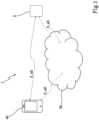
- the electronic system 1 for monitoring hydrogeological phenomena comprises:
- the electronic device 2 for monitoring hydrogeological phenomena is fixed (for example by means of fixing clamps) to a control surface S or on the surface of a side or bank A near a torrential channel affected by the passage of a debris flow C1, C2, C3.
- the electronic device 2 can be, by means of non-limiting example, planted with a picket on the ground or on snow or fixable by any other means. Where this is not possible, it is able to operate only through the anchoring of the legs.
- the electronic device 2 for monitoring hydrogeological phenomena is positioned on a control surface S or near a side or bank A (by means of non-limiting example, of a debris flow).
- control surface S on which the electronic device 2 is applied can be, by means of non-limiting example, constituted by a rockfall protection barrier, a net, an adhering panel, a flexible barrier for stopping debris flows, of a surface landslide, a landslide, a snowslide, a bank, a slope or an embankment or the bed of a stream or river.
- the electronic device 2 comprises one or more sensors or detection elements 4a, 4b, 4c, 4d having the function of converting a mechanical signal Fi into an electric signal Si_ril, as will be explained in more detail below.
- the telecommunications network 30 has the function of connecting the interactive electronic device 40 with the electronic device 2 for monitoring hydrogeological phenomena, by means of a network element (not shown in the figure).
- the network element has the function of running a software program indicated hereinafter with "server program".
- server program The network element is for example a computer server.
- the telecommunications network 30 can be of the fixed type (for example, Internet), mobile (for example, 2G, 3G, 4G or 5G mobile radio) or a combination of fixed and mobile.
- the telecommunications network 30 can be a wireless data communication network at low power for the application of the Internet of Things ( "IoT"), such as for example LoRa ® .
- IoT Internet of Things
- each electronic device 2 is also able to send and receive data signals to another adjacent electronic device 2 and so on, up to directly reaching the interactive electronic device 40 or until reaching an electronic device 2 reached by a fixed or mobile radio telecommunications network 30 of the 2G, 3G, 4G or 5G type.
- the resulting mechanical stress impacts one or more signalling legs 10, which in turn transmit the mechanical stress Fi to the detection element 4a, 4b, 4c, 4d, 4i to which each leg 10 is connected, and the relative movement between the contact element 12, 13 and the electrical contact 14 detects the occurrence of the event as such (alarm or warning).
- Figures 6a , 6b , 6c and 7a , 7b , 8c show the detection element of a mechanical type and the magnetic element.
- the spring 12 will have the classic eyelet that is fixed with a screw and bolt on one side to the leg 10 and on the other to the contact on the card, which (in turn could be magnetic or tearing) is activated in case of an event.
- the spring 12 is preferably dimensioned on the minimum activation energy.
- it is the magnet 13 which forms both contact and calibrated resistance on the activation energy. This is fixed on one side to the leg 10, and still through a bolt, on the other side to the electronics of the device 2.
- each detection element 4a, 4b, 4c, 4d is constituted by a sensor or position transducer, for example a contrast spring 12 or a magnet 13 that slides on a plate or electrical contact 14.
- the magnitude of the displacement or position of the spring or magnet with respect to the electrical contact 14 determines the measured magnitude unit S_mis characteristic of the mechanical stress Fi and it is determined for example by a measuring element 25 (a potentiometer, a proximity sensor or other) .
- the electrical power supply source 7 has the function of generating a DC voltage signal of the internal battery V bat_i for powering the electronic components inside the electronic device 2, such as the processing unit 20, the detection elements 4a, 4b, 4c, 4d and the signal transceiver 5.
- the electrical power supply source 7 is an electric battery of the LIPO type ("Lithium-lon Polymer Battery") composed of cells connected in series, such as to generate (at the terminals of the series of the cells) an internal battery voltage V bat_i having a value preferably comprised between 3.3 and 15 volts depending on the number of legs 10 or of detection elements 4a, 4b, 4c, 4d connected and of the autonomy required or the transmission power.
- photovoltaic panels 18 can be used, able to recharge the primary power supply source 7 during normal use or to provide an auxiliary charge in case of malfunction or low battery of the device 2.
- the wireless signal transceiver 5 can be long-range or short-range or both, and is powered by the power supply source 7.
- the long-range wireless signal transceiver 5 is electrically connected with the processing unit 20 and has the function of sending a long-range wireless signal S_w_Id carrying an alarm signal S_all in the event in which it was detected by the detection elements 4a, 4b, 4c, 4d, and then forwards said alarm signal generated by the processing unit 20 towards the interactive electronic device 40; furthermore the transceiver 5 has the function of transmitting the long-range wireless signal S_w_Id carrying the signal characteristic of the mechanical force Fi detected Si-ril by the detection elements 4a, 4b, 4c, 4d, and other signals relating to the operating state of the device and/or the battery and/or the position of the device.
- the long-range wireless signal S_w_Id is for example of the 2G, 3G, 4G or 5G mobile radio type or LoRa ® type.
- the short-range wireless signal transceiver 5 is electrically connected with the processing unit 20 and has the function of receiving a short-range wireless signal S_w_sd carrying an alarm signal S_all in the event in which it was detected by the detection elements 4a, 4b, 4c, 4d, and then forwards said alarm signal generated by the processing unit 20 towards the interactive electronic device 40; furthermore the transceiver 5 has the function of transmitting the short-range wireless signal S_w_Id carrying the signal characteristic of the mechanical force Fi detected S_ril by the detection elements 4a, 4b, 4c, 4d and other signals relating to the operating state of the device and/or the battery and/or the position of the device.
- the short-range wireless signals are for example of the Bluetooth or WiFi type.
- the processing unit 20 is electrically connected with the transceiver 5, with the memory unit 6, with one or more detection elements 4a, 4b, 4c, 4d by means of a communication bus.
- the processing unit 20 is for example a microprocessor, a microcontroller, a programmable electronic circuit or an integrated, dedicated circuit.
- processing unit 20 is considered to be split into distinct functional modules (storage modules or operating modules) for the sole purpose of describing its functionalities clearly and completely.
- Such processing unit can comprise a single electronic device, appropriately programmed to perform the functionalities described, and the different modules can correspond to hardware entities and/or routine software that are part of the programmed device.
- the aforementioned functional modules can also be distributed on different local or remote computers, depending on the architecture of the network in which they reside.
- the processing unit 20 is configured to process the detection data of a hydrogeological alarm, any malfunctioning of the device or battery, or low battery.
- Each detection element 4a, 4b, 4c, 4d is connectable to a first end of one or more signalling legs 10 by means of a coupling element 16.
- Each signalling leg 10 has a substantially elongated shape, and during use of the electronic device 2 for monitoring is coupled to the control surface S (for example by means of fixing clamps) or to the side or bank A of a debris flow (for example connecting the second free end to a weight or boulder directed towards the bottom or bed of the debris flow C1, C2, C3) and is configured so as to be able to transmit a mechanical stress Fi acting thereon to the detection element 4a, 4b, 4c, 4d which is connected and which in turn transforms it into an electric signal Si_ril.
- the signalling leg 10 comprises one or more joints 19.
- the presence of joints 19 allows adapting the leg 10 to the shape of the net or of the surface S on which the device 2 is applied.
- one or more detection elements 4a, 4b, 4c, 4d comprise an element capable of measuring the mechanical load and generating a signal Si_mis characteristic of the mechanical load Fi acting on the control surface S.
- the signalling legs 10 are one or more among at least bars, cables, wires or optic fibre cables.
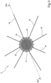
- the electronic device 2 for monitoring includes eight signalling legs 10.
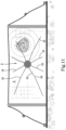
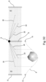
- the electronic device 2 is fixed in a substantially central position of the control surface S to be monitored, as shown in figures 9 , 10 , 11 , 12 , 13 , 14 , 15 , 16 , 17 , 23 , 24 and 26 .
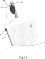
- the electronic device 2 is fixed on the central and/or side upright 11 (as shown in figures 31 and 32 , respectively), by means of screws or metal bands (as shown in figure 33 ) or equivalent fixing elements, so that the electronic device is solidly constrained to it.
- the signalling wires or legs 10 of the sensors are positioned in a minimum number of two legs 10 up to a maximum that depends on the electronics used, but can be, for example, in multiples of eight legs 10.
- the length of each signalling leg 10, which departs from the electronic device 2 and clamps on the net S, depends on the deformation coefficients of the net S, namely the energies for which the nets S are sized to withstand various types of impacts (in jargon "Energy Classes").
- the signalling legs 10 can be wires with a diameter varying from 1 mm to 15 mm, preferably from 1 mm to 7 mm, made of steel or other material, calculated to intervene on the expected deformation length of the net S at the established Energy Class. In one embodiment of the invention, it is possible to obtain on the same rockfall net devices 2 clamped to the upright 11 and/or within the net S.
- Figure 30 shows an electronic device 2 according to one embodiment, shaped substantially cylindrical, comprising a box-shaped casing 3, a first cover 3a, a sealing gasket 3c, an upper cover 3b and an antenna 50.
- the first cover 3a covers the area comprising the sensors 12, 13 and the electronics, while the second cover 3b covers the inner part of the device 2.
- the box-shaped casing 3 of the electronic device 2, as well as being substantially cylindrical or rounded, can also be of a square and/or rectangular shape.
- the signalling legs 10 extend in spoke-like fashion from the electronic device 2.
- the signalling legs 10 are substantially parallel to the control surface S.
- Each signalling leg 10 has the function of sensing every slightest vibration or mechanical stress acting on the control surface S. In particular, each leg 10 senses the stretching or tearing that takes place directly along the same leg and/or in the control surface S to which the leg 10 is connected.
- the legs 10 can be connected to a containment net, directly to a ground, a surface, or a system of beams.
- a mechanical stress or force Fi acting on the control surface S is mechanically transmitted to one or more legs 10 and determines a signal variation which is appropriately detected by the detection element 4a, 4b, 4c, 4d (to which they are connected) and processed by the processing unit 20, resulting in the sending of a danger or alarm signal Si_all to the interactive electronic device 40.
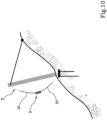
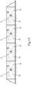
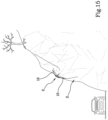
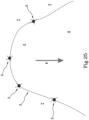
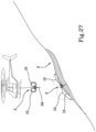
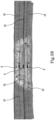
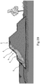
- the electronic device 2 is applicable to one or more among at least a rockfall protection barrier ( figures 9 , 10 , 11 , 12 and 13 ), an adhering net or panel ( figures 14 and 15 ), a flexible barrier for stopping debris flows ( figures 16 and 17 ), a catchment area affected by the passage of a debris flow ( figures 18, 19 and 20 ) a surface landslide ( figures 21, 22 , 23, 24 and 25 ), a snowslide ( figures 26 and 27 ), or a bank A ( figures 28 and 29 ).
- a rockfall protection barrier figures 9 , 10 , 11 , 12 and 13
- an adhering net or panel figures 14 and 15
- a flexible barrier for stopping debris flows figures 16 and 17
- a catchment area affected by the passage of a debris flow figures 18, 19 and 20
- a surface landslide figures 21, 22 , 23, 24 and 25
- a snowslide figures 26 and 27
- a bank A figures 28 and 29
- the electronic device 2 further comprises a receiver 8 of the geographical position on Earth of the electronic device 2, for example a satellite of the GPS type (Global Positioning System): in this case the electronic device 2 is able to provide the interactive electronic device 40 with the position in which it is installed.
- a receiver 8 of the geographical position on Earth of the electronic device 2 for example a satellite of the GPS type (Global Positioning System): in this case the electronic device 2 is able to provide the interactive electronic device 40 with the position in which it is installed.
- GPS type Global Positioning System
- the power supply source 7 is such as to further supply the geographical position receiver 8.
- the processing unit 20 is further electrically connected to the geographical position receiver 8.
- the wireless signal transceiver 5 is further configured to transmit, in addition to the alarm signal S_all, also the geographical position of the device 2.
- the use of the geographical position receiver 8 allows determining the position in which the electronic device 2 that has generated the alarm signal Si_all is located, received from the signal detector 4a, 4b, 4c, 4d of the i-th electronic device 2.
- the electronic device 2 further comprises an accelerometer 9 configured to detect vibrations and mechanical shocks acting directly or indirectly on the electronic device 2.
- the power supply source 7 is such as to further supply the accelerometer 9.
- the processing unit 20 is further electrically connected to the accelerometer 9.
- the electronic device 2 further comprises an electronic device that allows a mobile system (smartphone, tablet or other), when approached, to provide identifying information of the device, the system (barrier, net or other) and the instability event.
- a mobile system smart phone, tablet or other
- this system would allow the Civil Protection operators, those responsible for works, maintenance controllers, etc. to directly check technical data on-site that are typically difficult to obtain.
- the electronic device also acts as a database to provide both information and alerts.
- the present invention describes an electronic device for monitoring hydrogeological phenomena adapted to detect the stresses on a control surface S that can be the surface of a containment element (e.g., rockfall protection barrier, net, adhering panel) or directly the surface of the hydrogeological phenomenon to be monitored (for example, surface landslide, snowslide, bank).
- a containment element e.g., rockfall protection barrier, net, adhering panel
- directly the surface of the hydrogeological phenomenon to be monitored for example, surface landslide, snowslide, bank.
- the electronic device for monitoring hydrogeological phenomena adapted to detect the stresses on a control surface S is arranged within a box-shaped casing 3, the lower surface of which is rested on the control surface S.
- the electronic device 2 comprises one or more detection elements 4a, 4b, 4c, 4d configured to convert a mechanical signal Fi into an electric signal Si_ril characteristic of the mechanical load acting on the control surface of S.
- the electronic device 2 also comprises a signal transceiver 5 configured to transmit and receive data (short, medium and/or long-range), a memory unit 6 comprising a threshold value SOG; an electrical power supply source 7 configured to power the various elements of the device 2 and a processing unit 20, in connection with each of said detection elements 4a, 4b, 4c, 4d and with said signal transceiver 5, configured to process hydrogeological risk monitoring data.
- a signal transceiver 5 configured to transmit and receive data (short, medium and/or long-range)
- a memory unit 6 comprising a threshold value SOG
- an electrical power supply source 7 configured to power the various elements of the device 2
- a processing unit 20 in connection with each of said detection elements 4a, 4b, 4c, 4d and with said signal transceiver 5, configured to process hydrogeological risk monitoring data.
- the processing unit 20 comprises an input module 21 configured to receive said signal Si_ril from each of the detection elements 4a, 4b, 4c, 4d; a comparison module 22 configured to compare the signal Si_ril with a corresponding threshold value SOG; a transmission module 23 configured to transmit to the signal transceiver 5 an alarm signal S_all as a function of a match OK resulting from the comparison carried out by said comparison module 22.
- the processing unit 20 is advantageously configured to switch, as a function of the signals S_all; S_mis; S_bat possibly received from one or more of said detection elements 4a, 4b, 4c, 4d, the state of the electronic device 2 from a normal operating mode, wherein signal transceiver 5 of the electronic device 2 is able to transmit the signals S_all; S_mis; S_bat, to a standby mode, during which the electronic device 2 is such as to operate while minimising the consumption of electricity generated by the electric power supply source 7.
- This arrangement allows further saving the duration of the power supply source 7.
- Figures 9 and 11 show an electronic device 2 centrally applied to a rockfall net, for example of the type that overlies many rail and road sections.
- the falling rocks stopped by the nets is only detected "on sight” by the operator who must walk along the affected section up to the identification of the event after it has occurred.
- the electronic device With the electronic device according to the invention, it is possible to immediately know the situation when the event occurs, evaluate the consistency of the phenomenon and the damage to the barrier and decide on actions, practically in real time, at a very low cost and in a simple way, but above all protecting the safety of the operator who would otherwise go to verify the situation him or herself. A safety guarantee for both those working in the maintenance and management of the structures, as well as the people, businesses and societies protected by these structures.
- the electronic devices are also able to independently and directly operate acoustic or visual alerting devices or both configurations, with a wide range of easy programming and setting combinations.
- the present invention relates to an electronic device 2 for monitoring hydrogeological phenomena of the debris flow type, as shown in figures 18, 19 and 20 .
- the electronic device 2 and the signalling legs 10 connected thereto are identical to those described above in relation to the first aspect.
- the electronic device 2 is fixed on the side or bank A near a stream of a catchment basin which can be affected by hydrogeological phenomena, by means of non-limiting example, from possible debris flows C1, C2, C3.
- the signalling legs 10 are held “immersed” on the bed L of the stream at various heights, for example held in position with the free end of each leg 10 connected to a boulder or other object present.
- the electronic device 2 for monitoring is not rested on the control surface S as in the other embodiments of the invention, but is placed outside of it ( on the side or bank A), while the signalling legs 10 are oriented along a substantially oblique or perpendicular direction with respect to the surface of a possible debris flow C1, C2, C3.
- the signalling legs 10 extend to the bed L of the debris flow C1, C2, C3 to be monitored and are configured to transmit the mechanical load Fi acting on each of them to one of said detection elements 4a, 4b, 4c 4d.
- the electronic device 2 for monitoring hydrogeological phenomena is constituted by box-shaped casings 3a and 3b, joined by two or more connecting elements 17 and comprises a sensor or proximity transducer or accelerometer 15 and the elements already described in relation to the electronic device 2 shown in figures 2 , 3 and 4 .
- the lower element 3a is fixed on the control surface S (for example, a rocky volume or unstable boulder), while the signalling legs 10 extend from the upper element 3b and are fixed to an area T placed outside of the control surface S, not affected by the hydrogeological phenomena.
- the lower part 3a is fixed on the unstable surface S and solidly constrained to this.
- Both the sensitivity of the signalling legs 10 and the eventual signal S_acc coming from the accelerometer determine the activation of the electronic device 2 and the sending of the alarm signal S_all.
- the electronic device 2 shown in figures 23 and 24 can comprise a solar panel 18 arranged in the upper outer surface of the upper element 3b, and is configured to provide an additional source of electrical energy adapted to power the electronic device 2 and possibly also configured to recharge the battery 7. This will lengthen the life of the battery 7.
- the solar panel 18 can be present in each of the embodiments described herein.
- control surface S starts a movement or displacement, for example in the downstream direction, it moves the lower element 3a along with it, while the signalling legs 10 maintain the position of the upper element 3b fixed: a displacement towards its lower element 3a with respect to the upper element 3b is created.
- Figure 25 shows a system for monitoring hydrogeological events comprising a plurality of electronic devices 2 applied to the border of the control surface S, in such a way that some signalling legs 10 of each device 2 are fixed in the area T not affected by hydrogeological phenomena.
- the electronic device 2 for monitoring is substantially similar to that shown in figures 2 , 3 and 4 , and further comprises an elongated fixing element (such as a picket or similar element) firmly arranged on the lower surface (when in use) of the electronic device 2 for monitoring in such a way that, letting the electronic device 2 fall on the control surface S of a snowslide, it is planted on it in a stable and integral manner.
- an elongated fixing element such as a picket or similar element
- the signalling legs 10 are flexible and before depositing the electronic device 2 on the snowslide, are folded towards the centre of the upper surface of the electronic device 2 in such a way as not to obstruct or be damaged during the placement step on the snowslide to be monitored (usually, placed at high altitude).
- the legs 10 In the moment when the electronic device 2 is let fall from above by gravity on the point of the snowslide to be monitored, the legs 10 are in the folded position and, at the moment of impact with the surface S of the snowslide, the legs 10 unfold in spoke-like fashion in all directions and for their entire length or extension on the control surface S to be monitored.
- the unfolding of the legs 10 takes place automatically with the release of a mechanical device (not shown in the figures), once the tip 24 of the device 2 comes into contact with the surface.
- the electronic device 2 is used for monitoring the instability or collapse of bank or side defences of watercourses. Bank collapses often occur due to the presence of nutria or structural deterioration or also for incorrect realisation. To date, there are no monitoring systems if not precisely for such phenomena.
- the electronic device 2 allows detecting for long stretches of banks the potential deformation conditions of the side bank and allows quick reparation actions. The principle is still that of the legs 10 which in this case are much longer and made of fibre (optic, carbon) to be laid along the slopes and side banks A, with different configurations depending on the type of bank.
- the deformation of the detected bank corresponds to the deformation of the fibres and thus to the transmission of the alert signal S_all.
- the present invention relates to a system 1 for monitoring hydrogeological phenomena ( figure 1 ), comprising:
- the transmission of the alarm signal S_all generated by a first electronic device 2 is transmitted to the transceivers 5 of other adjacent electronic devices 2, up to reaching the transceiver of said fixed or mobile interactive electronic device 40, through a transmission of a point- point (single-band), point-to-multipoint (multiband) or point-to-all (broadcasting) type.
- the identification of the i-th electronic device 2(i) that has generated and transmitted a hydrogeological alarm signal Si_all takes place by means of a unique identification code cod_id sent together with the alarm signal Si_all.
- the signal Si_pos sent together with the alarm signal Si_all allows remotely and uniquely identifying (for example on the interactive device 40) the electronic device 2(i) that generated it.
- the electronic device 2 is able to send a low battery signal to the interactive device 40.
- the electronic device 2 sends a signal to the interactive electronic device 40.
- the present invention also relates to a kit for monitoring hydrogeological phenomena, comprising at least one electronic device 2 for monitoring as described herein and one or more signalling legs 10 that can be coupled thereto.
- the device can optionally be equipped with a non-volatile memory to function as a datalogger or simple detector.
- Both the acquisition system and the transmission are designed with very low power consumption technology on which specific functions have been implemented which are adapted to contain the consumption and optimise the transmission with loT protocols (SigFox, LoRa, etc.).
- the result is industrial-type electronics (extended temperature range) whose average consumption is in the order of microwatts/milliwatts.
- the transmission takes full advantage of the potential of loT networks, allowing an average sending of at least one "still alive" signal per day in the absence of events, and an increase, also progressive, of sending periodicity upon the occurrence of an event on one of the legs.
- the signals are transmitted by means of narrow-band Internet-of-Things technology and the radio module present in the electronic device is designed in such a way as to operate with a battery autonomy of at least 3-5 years.
- the sizing of the sensitive elements is governed by the rules that identify the energy classes to be used, therefore, on the production side a specific calibration is not necessary, rather, it becomes extremely easy to position the sensitive elements directly on the side of the electronics, closing the box-shaped container. During installation all that must be done is connecting the relative legs.
- the electronic device of the present invention can easily be customised for both "calibrated” sensors at energies different from the standard ones, and realising sensors with legs differentiated for specific purposes.
- the connection between the legs and the electronic device takes place by means of special clamping screws on the device itself.
- the latter can be solidly constrained or not to the structure on which it is installed, whether it is a rigid surface or a net or other (ground).
- the shape and materials used depend on the specific application, for example it is possible to insert it in floating containers, so that when faced with events such as debris flows or water avalanches, it is mainly brought to the surface to ensure the maximum probability of transmission of the signal, maximising the power in transmission.
- the system can reduce its consumption to almost zero by allowing autonomy of up to many years with small batteries. At the same time it provides a self-diagnosis to allow the identification of failures or transmission failure.
- each transmission in fact also communicates two important points of information: the status of the battery and the geographic coordinates.
- the first is basic information for understanding the system's status and allows planning a possible rapid replacement of the batteries, the second allows its recovery in the case when, faced with a very important event, it has been torn or pushed away but not submerged.
- the power supply source 7 envisaged is a battery, but it is possible to insert small solar panels to make the device completely autonomous with internal recharging.
- the invention allows overcoming the drawbacks previously highlighted with reference to the prior art.
- the present invention allows improving the monitoring of hydrogeological phenomena in inaccessible areas, not reached by 2G, 3G, 4G mobile telecommunications networks or the electrical power grid.
- it allows better management and monitoring of installed devices, without having to reach them to control their operating status.
- the electronic device is compact and robust. The simplicity of the sensors and their robustness minimises maintenance activities, making the electronic device of the present invention adapted to all monitoring and alerting applications, also under extreme environmental conditions.
- the device according to the invention is for both monitoring and alerting, as in the instant when it detects a hydrogeological risk, it sends an alarm signal and also an acoustic and visual alert signal, both from the site where it is positioned and remotely. Furthermore, the device according to the present invention not only finds use in prevention, but also and especially, in the case of a hydrogeological event and after the event. Finally, the device has an application in the field of alert management in the field of hydrogeological and engineering instability, but also by Civil Defense in an emergency, to allow operators to manage the progress of hydrological phenomena. It is clear that the specific characteristics are described in relation to different embodiments of the invention with an exemplifying and non-limiting intention.
Landscapes
- Physics & Mathematics (AREA)
- General Physics & Mathematics (AREA)
- Business, Economics & Management (AREA)
- Emergency Management (AREA)
- Engineering & Computer Science (AREA)
- Life Sciences & Earth Sciences (AREA)
- Environmental & Geological Engineering (AREA)
- General Life Sciences & Earth Sciences (AREA)
- Geology (AREA)
- Aviation & Aerospace Engineering (AREA)
- Architecture (AREA)
- Civil Engineering (AREA)
- Structural Engineering (AREA)
- Testing Or Calibration Of Command Recording Devices (AREA)
- Force Measurement Appropriate To Specific Purposes (AREA)
- Devices Affording Protection Of Roads Or Walls For Sound Insulation (AREA)
- Management, Administration, Business Operations System, And Electronic Commerce (AREA)
- Pit Excavations, Shoring, Fill Or Stabilisation Of Slopes (AREA)
- Telephonic Communication Services (AREA)
- Arrangements For Transmission Of Measured Signals (AREA)
- Investigating Or Analysing Materials By The Use Of Chemical Reactions (AREA)
- External Artificial Organs (AREA)
Claims (15)
- Elektronische Vorrichtung (2) zur Überwachung hydrogeologischer Phänomene, die geeignet ist, Spannungen einer Steuerfläche (S) zu erfassen, umfassend:- ein kastenförmiges Gehäuse (3), das auf der Steuerfläche (S) aufliegt;- ein oder mehrere Erfassungselemente (4a, 4b, 4c, 4d), die so konfiguriert sind, dass sie ein mechanisches Signal (Fi) in ein elektrisches Signal (Si_ril) umwandeln, das für die auf die Steuerfläche (S) wirkende mechanische Belastung charakteristisch ist;- eine Vielzahl von sich speichenartig von der elektronischen Vorrichtung erstreckenden Signalisierungsbeinen (10), die sich parallel zu der Steuerfläche (S) erstrecken und so konfiguriert sind, dass sie die mechanische Belastung (Fi), die auf die Steuerfläche (S) wirkt, zu einem der Erfassungselemente (4a, 4b, 4c, 4d) übertragen, wobei jedes Erfassungselement (4a, 4b, 4c, 4d) mit einem oder mehreren der Signalisierungsbeine (10) verbunden ist;- einen Signal-Transceiver (5), der zum Senden und Empfangen von Daten konfiguriert ist;- eine Speichereinheit (6), die einen Schwellenwert (SOG) umfasst;- eine elektrische Stromversorgungsquelle (7), die so konfiguriert ist, dass sie die verschiedenen Elemente der elektronischen Vorrichtung (2) mit Strom versorgt;- eine Verarbeitungseinheit (20), die mit jedem der Erfassungselemente (4a, 4b, 4c, 4d) und mit dem Signal-Transceiver (5) verbunden ist und so konfiguriert ist, dass sie Daten der Überwachung eines hydrogeologischen Risikos verarbeitet, umfassend:• ein Eingangsmodul (21), das so konfiguriert ist, dass es das elektrische Signal (Si_ril) von jedem der Erfassungselemente (4a, 4b, 4c, 4d) empfängt;• ein Vergleichsmodul (22), das so konfiguriert ist, dass es das elektrische Signal (Si_ril) mit dem entsprechenden Schwellenwert (SOG) von der Speichereinheit (6) vergleicht;• ein Übertragungsmodul (23), das so konfiguriert ist, dass es in Abhängigkeit von einer Übereinstimmung (OK), die sich aus dem von dem Vergleichsmodul (22) durchgeführten Vergleich ergibt, ein Alarmsignal (S_all) zu dem Signal-Transceiver (5) überträgt.
- Elektronische Vorrichtung (2) nach Anspruch 1, wobei eines oder mehrere der Erfassungselemente (4a, 4b, 4c, 4d) ein Element umfassen, das in der Lage ist, die mechanische Belastung zu messen und ein Signal (Si_mis) zu erzeugen, das für die auf die Steuerfläche (S) wirkende mechanische Belastung (Fi) charakteristisch ist.
- Elektronische Vorrichtung (2) nach einem oder mehreren der vorhergehenden Ansprüche, wobei die Beine (10) eines oder mehrere sind von mindestens:• Stangen;• Kabeln;• Drähten;• Glasfaserkabeln.
- Elektronische Vorrichtung (2) nach einem oder mehreren der vorhergehenden Ansprüche, die acht Signalisierungsbeine (10) umfasst.
- Elektronische Vorrichtung (2) nach einem oder mehreren der vorhergehenden Ansprüche, wobei die elektronische Vorrichtung (2) auf eines oder mehrere anwendbar ist von mindestens:- einer Steinschlagschutzbarriere;- einem anhaftenden Netz oder Paneel;- einer flexiblen Trümmerbarriere;- einem Murgang;- einem Erdrutsch an der Oberfläche;- einen Schneerutsch;- einem Ufer (A).
- Elektronische Vorrichtung (2) nach einem oder mehreren der vorhergehenden Ansprüche, wobei der Signal-Transceiver (5) so konfiguriert ist, dass er mit einem interaktiven elektronischen Gerät (40) über ein Telekommunikationsnetz (30) mit großer Reichweite verbunden ist.
- Elektronische Vorrichtung (2) nach einem oder mehreren der vorhergehenden Ansprüche, wobei der Signal-Transceiver (5) einer ersten elektronischen Vorrichtung (2) so konfiguriert ist, dass er Daten von dem Transceiver (5) einer oder mehrerer elektronischer Vorrichtungen (2) sendet und empfängt.
- Elektronische Vorrichtung (2) nach einem oder mehreren der vorhergehenden Ansprüche, umfassend Mittel (8), die geeignet sind, eine geographische Position der elektronischen Vorrichtung (2) zu bestimmen und ein Signal (S_pos) zu erzeugen, das die geographische Position anzeigt.
- Elektronische Vorrichtung (2) zur Überwachung hydrogeologischer Phänomene, die geeignet ist, Spannungen von Murgängen (C1, C2, C3) zu erfassen, umfassend:- ein kastenförmiges Gehäuse (3), das auf der Seite oder dem Ufer (A) eines Wasserlaufs aufliegt, der von dem Durchgang eines Murgangs (C1, C2, C3) betroffen ist;- ein oder mehrere Erfassungselemente (4a, 4b, 4c, 4d), die so konfiguriert sind, dass sie ein mechanisches Signal (Fi) in ein elektrisches Signal (Si_ril) umwandeln, das für die auf die Steuerfläche (S) wirkende mechanische Belastung charakteristisch ist;- einen Signal-Transceiver (5), der zum Senden und Empfangen von Daten konfiguriert ist;- eine Speichereinheit (6), die einen Schwellenwert (SOG) umfasst;- eine elektrische Stromversorgungsquelle (7), die so konfiguriert ist, dass sie die verschiedenen Elemente der elektronischen Vorrichtung (2) mit Strom versorgt;- eine Verarbeitungseinheit (20), die mit jedem der Erfassungselemente (4a, 4b, 4c, 4d) und mit dem Signal-Transceiver (5) verbunden ist und so konfiguriert ist, dass sie Daten der Überwachung eines hydrogeologischen Risikos verarbeitet, umfassend:- ein Eingangsmodul (21), das so konfiguriert ist, dass es das elektrische Signal (Si_ril) von jedem der Erfassungselemente (4a, 4b, 4c, 4d) empfängt;- ein Vergleichsmodul (22), das so konfiguriert ist, dass es das Signal (Si_ril) mit dem entsprechenden Schwellenwert (SOG) von der Speichereinheit (6) vergleicht;- ein Übertragungsmodul (23), das so konfiguriert ist, dass es in Abhängigkeit von einer Übereinstimmung (OK), die sich aus dem von dem Vergleichsmodul (22) durchgeführten Vergleich ergibt, ein Alarmsignal (S_all) zu dem Signal-Transceiver (5) überträgt;wobei die elektronische Vorrichtung (2) eine Vielzahl von Signalbeinen (10) umfasst, die sich bis zu einem Bett (L) des zu überwachenden Murgangs (C1, C2, C3) erstrecken und so konfiguriert sind, dass sie die mechanische Belastung (Fi), die auf jedes von ihnen wirkt, zu einem der Erfassungselemente (4a, 4b, 4c, 4d) übertragen, wobei sich die Signalisierungsbeine speichenartig von der elektronischen Vorrichtung aus erstrecken und auf dem Bachbett in verschiedenen Höhen eingetaucht sind und entlang einer im Wesentlichen schrägen oder senkrechten Richtung in Bezug auf die Oberfläche eines möglichen Murgangs ausgerichtet sind, wobei jedes Erfassungselement (4a, 4b, 4c, 4d) mit einem oder mehreren der Signalisierungsbeine (10) verbunden ist.
- Elektronische Vorrichtung (2) nach Anspruch 9, wobei das freie Ende (3b) des Signalisierungsbeins (10) mit einem schweren Gegenstand verbunden ist, der auf dem Bett (L) des Murgangs (C1, C2, C3) ruht.
- Elektronische Vorrichtung (2) nach einem oder mehreren der vorhergehenden Ansprüche, wobei die Verarbeitungseinheit (20) so konfiguriert ist, dass sie in Abhängigkeit von Signalen (S_all; S_mis; S_bat), die von einem oder mehreren der Erfassungselemente (4a, 4b, 4c, 4d) empfangen werden, den Status der elektronischen Vorrichtung (2) von einem normalen Betriebsmodus, in dem der Signal-Transceiver (5) der elektronischen Vorrichtung (2) die Signale (S_all; S_mis; S_bat) übertragen kann, in einen Standby-Modus umschaltet, in dem die elektronische Vorrichtung (2) so funktioniert, dass sie den Verbrauch der von der Stromversorgungsquelle (7) erzeugten elektrischen Energie minimiert.
- System zur Überwachung hydrogeologischer Phänomene, das Folgendes umfasst:- eine elektronische Vorrichtung (2) zur Überwachung hydrogeologischer Phänomene nach einem der vorhergehenden Ansprüche;- ein mobiles oder festes interaktives elektronisches Gerät (40), das einen Signal-Transceiver umfasst, der so konfiguriert ist, dass er ein Alarmsignal (S_all) empfängt, das einen hydrogeologischen Gefahrenzustand anzeigt, der von einer oder mehreren elektronischen Vorrichtungen (2) erfasst und zu dem Transceiver (5) übertragen wird.
- System zur Überwachung hydrogeologischer Phänomene nach Anspruch 12, das ein Telekommunikationsnetz (30) mit großer Reichweite umfasst, das so konfiguriert ist, dass es das interaktive elektronische Gerät (40) mit der elektronischen Vorrichtung (2) zur Überwachung hydrogeologischer Phänomene verbindet.
- System zur Überwachung hydrogeologischer Phänomene nach Anspruch 12 oder 13, wobei die Übertragung des Alarmsignals (S_all), das von einer ersten elektronischen Vorrichtung (2) erzeugt wird, zu den Transceivern (5) anderer elektronischer Vorrichtungen (2) bis zum Erreichen des Transceivers des besagten festen oder mobilen interaktiven elektronischen Geräts (40) durch eine Übertragung des folgenden Typs übertragen wird:- Punkt-zu-Punkt;- Punkt-zu-Multipunkt;- Punkt-zu-allen Punkten.
- Verfahren zur Überwachung hydrogeologischer Phänomene, das die folgenden Schritte umfasst:a) speichenartiges Anlegen einer Vielzahl von Signalisierungsbeinen (10) an ein Erfassungselement (4a, 4b, 4c, 4d) einer elektronischen Vorrichtung (2) zur Überwachung hydrogeologischer Phänomene nach einem oder mehreren der Ansprüche 1 bis 11;b) Anlegen der elektronischen Vorrichtung (2) zur Überwachung hydrogeologischer Phänomene und der Vielzahl von Signalisierungsbeinen (10) an eine Steuerfläche (S);c) Erfassen eines mechanischen Signals (Fi), das auf die Oberfläche (S) wirkt, mit Hilfe des Signalisierungsbeins (10);d) Umwandeln des mechanischen Signals (Fi) in ein elektrisches Signal (Si_ril), das für die auf die Steuerfläche (S) wirkende mechanische Belastung charakteristisch ist;e) Empfangen des elektrischen Signals (Si_ril) von dem Erfassungselement (4a, 4b, 4c, 4d);f) Vergleichen des elektrischen Signals (Si_ril) mit einem entsprechenden Schwellenwert (SOG), der in einer Speichereinheit (6) gespeichert ist;g) Senden eines hydrogeologischen Risikoalarmsignals (S_all) an einen Signal-Transceiver (5) in Abhängigkeit von einer verifizierten Übereinstimmung (OK), die sich aus dem von dem Vergleichsmodul (22) durchgeführten Vergleich ergibt;h) Übertragen des Alarmsignals (S_all) zu dem Transceiver einer zweiten elektronischen Vorrichtung (2) zur Überwachung hydrogeologischer Phänomene oder zu dem Transceiver eines festen oder mobilen interaktiven elektronischen Geräts (40).
Priority Applications (4)
| Application Number | Priority Date | Filing Date | Title |
|---|---|---|---|
| RS20250885A RS67178B1 (sr) | 2018-07-31 | 2019-07-30 | Sistem i metod za praćenje hidrogeološkog rizika |
| HRP20251012TT HRP20251012T1 (hr) | 2018-07-31 | 2019-07-30 | Sustav i postupak nadziranja hidrogeološkog rizika |
| SM20250319T SMT202500319T1 (it) | 2018-07-31 | 2019-07-30 | Sistema e metodo di monitoraggio di rischio idrogeologico |
| SI201930961T SI3830342T1 (sl) | 2018-07-31 | 2019-07-30 | Sistem in postopek za spremljanje hidrogeološkega tveganja |
Applications Claiming Priority (2)
| Application Number | Priority Date | Filing Date | Title |
|---|---|---|---|
| IT102018000007671A IT201800007671A1 (it) | 2018-07-31 | 2018-07-31 | Sistema e metodo di monitoraggio di rischio idrogeologico |
| PCT/IB2019/056486 WO2020026137A1 (en) | 2018-07-31 | 2019-07-30 | System and method for monitoring hydrogeological risk |
Publications (2)
| Publication Number | Publication Date |
|---|---|
| EP3830342A1 EP3830342A1 (de) | 2021-06-09 |
| EP3830342B1 true EP3830342B1 (de) | 2025-06-25 |
Family
ID=63896542
Family Applications (1)
| Application Number | Title | Priority Date | Filing Date |
|---|---|---|---|
| EP19768906.0A Active EP3830342B1 (de) | 2018-07-31 | 2019-07-30 | System und verfahren zur überwachung hydrogeologischer risiken |
Country Status (19)
| Country | Link |
|---|---|
| US (1) | US12146815B2 (de) |
| EP (1) | EP3830342B1 (de) |
| JP (2) | JP7593923B2 (de) |
| CN (1) | CN112771229A (de) |
| AU (2) | AU2019312911A1 (de) |
| DK (1) | DK3830342T3 (de) |
| ES (1) | ES3040120T3 (de) |
| FI (1) | FI3830342T3 (de) |
| HR (1) | HRP20251012T1 (de) |
| HU (1) | HUE072670T2 (de) |
| IT (1) | IT201800007671A1 (de) |
| LT (1) | LT3830342T (de) |
| PL (1) | PL3830342T3 (de) |
| PT (1) | PT3830342T (de) |
| RS (1) | RS67178B1 (de) |
| SI (1) | SI3830342T1 (de) |
| SM (1) | SMT202500319T1 (de) |
| WO (1) | WO2020026137A1 (de) |
| ZA (1) | ZA202100826B (de) |
Families Citing this family (16)
| Publication number | Priority date | Publication date | Assignee | Title |
|---|---|---|---|---|
| IT201800004022A1 (it) * | 2018-03-28 | 2019-09-28 | Maccaferri Off Spa | Rete metallica sensorizzata |
| NO345259B1 (en) * | 2018-06-12 | 2020-11-23 | Kahrs Hansen As | Instrumentation system for integrity monitoring of a net barrier |
| IT202100022457A1 (it) * | 2021-08-27 | 2023-02-27 | Gp2 S R L | Sistema e metodo di monitoraggio in continuo e da remoto della integritá di elementi di protezione |
| CN115083115B (zh) * | 2022-06-14 | 2023-11-03 | 成都理工大学 | 一种降雨与温度升高共同作用诱发的泥石流预警方法 |
| CN115083117B (zh) * | 2022-06-14 | 2023-08-04 | 成都理工大学 | 一种用于后期冰水泥石流的预警方法及其应用 |
| CN115063948B (zh) * | 2022-06-14 | 2023-08-04 | 成都理工大学 | 一种积雪消融期冰水泥石流预警方法 |
| CN115273407B (zh) * | 2022-07-22 | 2023-10-24 | 四川大学 | 山区小流域暴雨山洪积水深度远程监测报警杆 |
| CN115450234B (zh) * | 2022-11-10 | 2023-03-24 | 中国铁道科学研究院集团有限公司铁道建筑研究所 | 一种适用高能冲击的拦挡防护结构及其施工方法 |
| CN115451796B (zh) * | 2022-11-14 | 2023-02-03 | 山东省鲁南地质工程勘察院(山东省地质矿产勘查开发局第二地质大队) | 一种堤坝土质边坡的变形检测装置 |
| CN115680537A (zh) * | 2023-01-01 | 2023-02-03 | 中国有色金属工业昆明勘察设计研究院有限公司 | 一种用于水压致裂法地应力测试中的钻孔碎屑收集装置 |
| DE102023106201A1 (de) * | 2023-03-13 | 2024-09-19 | Königl GmbH & Co. KG Felssicherung und Zaunbau | Sicherungseinheit und Überwachungssystem |
| DE102023107130A1 (de) * | 2023-03-21 | 2024-09-26 | Geobrugg Ag | Modulares Stützensystem für Schutznetzverbauungen |
| AT527332B1 (de) * | 2023-06-28 | 2025-08-15 | Weingarth Steve | Steinschlag- und lawinenfrühwarnsystem |
| DE102024101497A1 (de) * | 2024-01-18 | 2025-07-24 | Breitbach Grundbau GmbH | Verfahren zur Verhinderung von Steinschlag oder dgl. und Netzanordnung hierfür |
| CN118895790A (zh) * | 2024-07-17 | 2024-11-05 | 甘肃水利机械化工程有限责任公司 | 一种水利工程边坡稳定性监测装置及其使用方法 |
| CN119296265B (zh) * | 2024-12-12 | 2025-06-06 | 宁波市谦诺科技有限公司 | 一种新型地质灾害崩塌探测装置及探测方法 |
Family Cites Families (18)
| Publication number | Priority date | Publication date | Assignee | Title |
|---|---|---|---|---|
| JPS5551879Y2 (de) * | 1976-02-03 | 1980-12-02 | ||
| CH637435A5 (de) * | 1979-05-05 | 1983-07-29 | Brugg Ag Kabelwerke | Sicherungsanlage zur sicherung von hinter derselben gelegenen objekten mit mindestens einem drahtseilnetz. |
| GB9408876D0 (en) * | 1994-05-04 | 1994-06-22 | Bilak Roman | Snow pack stability monitor |
| JP2000097737A (ja) * | 1998-09-28 | 2000-04-07 | Babcock Hitachi Kk | 落石・崩落監視システム |
| JP2002228497A (ja) * | 2001-02-06 | 2002-08-14 | Hitachi Cable Ltd | 落石防護ネット警報装置 |
| JP2003082625A (ja) * | 2001-09-07 | 2003-03-19 | Hiroaki Yanagida | 歪み検知機能付き防護柵及び異常検知システム |
| JP4145731B2 (ja) * | 2003-06-19 | 2008-09-03 | 株式会社 復建技術コンサルタント | 落石検出装置および落石検出システム |
| JP4586134B2 (ja) * | 2005-09-07 | 2010-11-24 | 日本ゼニスパイプ株式会社 | 落石等の受撃検出装置 |
| TW200923401A (en) * | 2007-11-16 | 2009-06-01 | Higher Way Electronic Co Ltd | Using solar energy and wireless sensor network on the establishment of real-time monitoring system and method |
| JP2009203681A (ja) * | 2008-02-27 | 2009-09-10 | Purotekku Engineering:Kk | 落石防止構造と落石防止方法 |
| CN102289912A (zh) * | 2011-05-11 | 2011-12-21 | 东北大学秦皇岛分校 | 基于物联网的地震应急防灾方法及系统 |
| US9757050B2 (en) * | 2011-08-05 | 2017-09-12 | Mc10, Inc. | Catheter balloon employing force sensing elements |
| CN102354433B (zh) * | 2011-10-14 | 2013-06-19 | 武汉理工光科股份有限公司 | 基于光纤光栅传感技术的铁路边坡危岩落石监测报警系统 |
| CN103132468A (zh) * | 2011-12-04 | 2013-06-05 | 西安金和光学科技有限公司 | 一种智能防护网 |
| CN102787564A (zh) * | 2012-09-07 | 2012-11-21 | 四川三义边坡防护工程有限公司 | 具有实时监测功能的被动防护网系统及其实现方法 |
| CN103985225B (zh) * | 2013-02-08 | 2016-12-28 | 同方威视技术股份有限公司 | 柔性被动防护网智能监测系统 |
| JP2017091440A (ja) * | 2015-11-17 | 2017-05-25 | ソニー株式会社 | 防災システム及び防災方法 |
| CN110411622B (zh) * | 2018-04-28 | 2024-07-16 | 五邑大学 | 一种全纺织应力传感器 |
-
2018
- 2018-07-31 IT IT102018000007671A patent/IT201800007671A1/it unknown
-
2019
- 2019-07-30 PL PL19768906.0T patent/PL3830342T3/pl unknown
- 2019-07-30 AU AU2019312911A patent/AU2019312911A1/en not_active Abandoned
- 2019-07-30 EP EP19768906.0A patent/EP3830342B1/de active Active
- 2019-07-30 JP JP2021529540A patent/JP7593923B2/ja active Active
- 2019-07-30 CN CN201980064247.0A patent/CN112771229A/zh active Pending
- 2019-07-30 ES ES19768906T patent/ES3040120T3/es active Active
- 2019-07-30 RS RS20250885A patent/RS67178B1/sr unknown
- 2019-07-30 FI FIEP19768906.0T patent/FI3830342T3/fi active
- 2019-07-30 PT PT197689060T patent/PT3830342T/pt unknown
- 2019-07-30 WO PCT/IB2019/056486 patent/WO2020026137A1/en not_active Ceased
- 2019-07-30 HU HUE19768906A patent/HUE072670T2/hu unknown
- 2019-07-30 US US17/265,028 patent/US12146815B2/en active Active
- 2019-07-30 HR HRP20251012TT patent/HRP20251012T1/hr unknown
- 2019-07-30 LT LTEPPCT/IB2019/056486T patent/LT3830342T/lt unknown
- 2019-07-30 DK DK19768906.0T patent/DK3830342T3/da active
- 2019-07-30 SM SM20250319T patent/SMT202500319T1/it unknown
- 2019-07-30 SI SI201930961T patent/SI3830342T1/sl unknown
-
2021
- 2021-02-05 ZA ZA2021/00826A patent/ZA202100826B/en unknown
-
2024
- 2024-07-26 AU AU2024205113A patent/AU2024205113A1/en active Pending
- 2024-09-30 JP JP2024169731A patent/JP7805414B2/ja active Active
Also Published As
| Publication number | Publication date |
|---|---|
| JP2021533393A (ja) | 2021-12-02 |
| IT201800007671A1 (it) | 2020-01-31 |
| AU2024205113A1 (en) | 2024-08-15 |
| JP7805414B2 (ja) | 2026-01-23 |
| JP2025000826A (ja) | 2025-01-07 |
| PL3830342T3 (pl) | 2025-10-20 |
| CN112771229A (zh) | 2021-05-07 |
| RS67178B1 (sr) | 2025-09-30 |
| ZA202100826B (en) | 2022-09-28 |
| SI3830342T1 (sl) | 2025-10-30 |
| HUE072670T2 (hu) | 2025-12-28 |
| ES3040120T3 (en) | 2025-10-28 |
| PT3830342T (pt) | 2025-09-08 |
| FI3830342T3 (fi) | 2025-08-08 |
| EP3830342A1 (de) | 2021-06-09 |
| DK3830342T3 (da) | 2025-09-15 |
| JP7593923B2 (ja) | 2024-12-03 |
| SMT202500319T1 (it) | 2025-11-10 |
| US12146815B2 (en) | 2024-11-19 |
| US20210302268A1 (en) | 2021-09-30 |
| HRP20251012T1 (hr) | 2025-10-24 |
| BR112021001659A2 (pt) | 2021-05-04 |
| WO2020026137A1 (en) | 2020-02-06 |
| AU2019312911A1 (en) | 2021-03-18 |
| LT3830342T (lt) | 2025-09-10 |
Similar Documents
| Publication | Publication Date | Title |
|---|---|---|
| EP3830342B1 (de) | System und verfahren zur überwachung hydrogeologischer risiken | |
| EP3524948B1 (de) | System zur automatischen drahtlosen überwachung, ferngesteuert und in echtzeit, von strukturen, infrastrukturen und berghangsektoren | |
| KR101880472B1 (ko) | LPWA(Low-Power Wide-Area) 네트워크 기반의 지하시설물 상태 모니터링을 위한 맨홀 커버 | |
| CN102013150B (zh) | 基于雨强、斜坡土壤含水量和形变量的地质灾害预测系统 | |
| KR101365688B1 (ko) | 도로 침수 감지 장치를 이용한 도로 침수 안내 시스템 | |
| KR101586011B1 (ko) | 충돌 감지 장치를 가지는 도로 펜스 장치 | |
| US12530955B2 (en) | Flood monitoring unit and system | |
| KR101391388B1 (ko) | 차량 통행 제한장치 및 이에 설치되는 태양광 재난 감시시스템 | |
| CN104655101A (zh) | 高精度导线式全断面边坡稳定监测预警系统及其监测方法 | |
| CN212694553U (zh) | 一种地下管线防外破预警警示桩 | |
| CN102749652B (zh) | 山体滑坡电子监测系统及监测方法 | |
| CN106066388A (zh) | 自主式边坡监测系统 | |
| CN205334687U (zh) | 一种泥石流监测预警系统 | |
| JP2002228497A (ja) | 落石防護ネット警報装置 | |
| CN106887117A (zh) | 一种泥石流监测预警系统 | |
| KR102632463B1 (ko) | 도심지 침수 모니터링 시스템 | |
| KR101140768B1 (ko) | 원격 제설 방재 시스템 | |
| KR102155529B1 (ko) | 터널 선행침하 경보장치 | |
| KR101633737B1 (ko) | 지역단위별 토사층 붕괴여부 감지시스템 | |
| JP4422174B2 (ja) | 落石監視装置 | |
| JP2011047252A (ja) | 落石・土砂崩落検知システム | |
| CN218041584U (zh) | 环境采集监控设备 | |
| BR112021001659B1 (pt) | Dispositivo eletrônico, sistema e método para monitorar fenômenos hidrogeológicos | |
| KR100270886B1 (ko) | 절개지 사면 붕괴 경보 장치 | |
| KR102635185B1 (ko) | 지표면 수위 계측장치 |
Legal Events
| Date | Code | Title | Description |
|---|---|---|---|
| REG | Reference to a national code |
Ref country code: HR Ref legal event code: TUEP Ref document number: P20251012T Country of ref document: HR |
|
| STAA | Information on the status of an ep patent application or granted ep patent |
Free format text: STATUS: UNKNOWN |
|
| STAA | Information on the status of an ep patent application or granted ep patent |
Free format text: STATUS: THE INTERNATIONAL PUBLICATION HAS BEEN MADE |
|
| TPAC | Observations filed by third parties |
Free format text: ORIGINAL CODE: EPIDOSNTIPA |
|
| PUAI | Public reference made under article 153(3) epc to a published international application that has entered the european phase |
Free format text: ORIGINAL CODE: 0009012 |
|
| STAA | Information on the status of an ep patent application or granted ep patent |
Free format text: STATUS: REQUEST FOR EXAMINATION WAS MADE |
|
| 17P | Request for examination filed |
Effective date: 20210211 |
|
| AK | Designated contracting states |
Kind code of ref document: A1 Designated state(s): AL AT BE BG CH CY CZ DE DK EE ES FI FR GB GR HR HU IE IS IT LI LT LU LV MC MK MT NL NO PL PT RO RS SE SI SK SM TR |
|
| DAV | Request for validation of the european patent (deleted) | ||
| DAX | Request for extension of the european patent (deleted) | ||
| STAA | Information on the status of an ep patent application or granted ep patent |
Free format text: STATUS: EXAMINATION IS IN PROGRESS |
|
| 17Q | First examination report despatched |
Effective date: 20230425 |
|
| P01 | Opt-out of the competence of the unified patent court (upc) registered |
Effective date: 20230607 |
|
| RAP1 | Party data changed (applicant data changed or rights of an application transferred) |
Owner name: OFFICINE MACCAFERRI S.P.A. |
|
| RAP3 | Party data changed (applicant data changed or rights of an application transferred) |
Owner name: OFFICINE MACCAFERRI S.P.A. |
|
| RAP3 | Party data changed (applicant data changed or rights of an application transferred) |
Owner name: OFFICINE MACCAFERRI S.P.A. |
|
| GRAP | Despatch of communication of intention to grant a patent |
Free format text: ORIGINAL CODE: EPIDOSNIGR1 |
|
| STAA | Information on the status of an ep patent application or granted ep patent |
Free format text: STATUS: GRANT OF PATENT IS INTENDED |
|
| INTG | Intention to grant announced |
Effective date: 20250122 |
|
| GRAS | Grant fee paid |
Free format text: ORIGINAL CODE: EPIDOSNIGR3 |
|
| GRAA | (expected) grant |
Free format text: ORIGINAL CODE: 0009210 |
|
| STAA | Information on the status of an ep patent application or granted ep patent |
Free format text: STATUS: THE PATENT HAS BEEN GRANTED |
|
| AK | Designated contracting states |
Kind code of ref document: B1 Designated state(s): AL AT BE BG CH CY CZ DE DK EE ES FI FR GB GR HR HU IE IS IT LI LT LU LV MC MK MT NL NO PL PT RO RS SE SI SK SM TR |
|
| REG | Reference to a national code |
Ref country code: GB Ref legal event code: FG4D |
|
| REG | Reference to a national code |
Ref country code: CH Ref legal event code: EP |
|
| REG | Reference to a national code |
Ref country code: CH Ref legal event code: EP |
|
| REG | Reference to a national code |
Ref country code: IE Ref legal event code: FG4D |
|
| REG | Reference to a national code |
Ref country code: DE Ref legal event code: R096 Ref document number: 602019071591 Country of ref document: DE |
|
| REG | Reference to a national code |
Ref country code: FI Ref legal event code: FGE |
|
| PGFP | Annual fee paid to national office [announced via postgrant information from national office to epo] |
Ref country code: NL Payment date: 20250721 Year of fee payment: 7 Ref country code: LU Payment date: 20250721 Year of fee payment: 7 |
|
| REG | Reference to a national code |
Ref country code: NL Ref legal event code: FP |
|
| REG | Reference to a national code |
Ref country code: PT Ref legal event code: SC4A Ref document number: 3830342 Country of ref document: PT Date of ref document: 20250908 Kind code of ref document: T Free format text: AVAILABILITY OF NATIONAL TRANSLATION Effective date: 20250901 |
|
| REG | Reference to a national code |
Ref country code: DK Ref legal event code: T3 Effective date: 20250912 |
|
| PGFP | Annual fee paid to national office [announced via postgrant information from national office to epo] |
Ref country code: SM Payment date: 20250904 Year of fee payment: 7 |
|
| REG | Reference to a national code |
Ref country code: SE Ref legal event code: TRGR |
|
| PGFP | Annual fee paid to national office [announced via postgrant information from national office to epo] |
Ref country code: ES Payment date: 20250827 Year of fee payment: 7 Ref country code: FI Payment date: 20250822 Year of fee payment: 7 |
|
| PGFP | Annual fee paid to national office [announced via postgrant information from national office to epo] |
Ref country code: LT Payment date: 20250710 Year of fee payment: 7 Ref country code: DE Payment date: 20250722 Year of fee payment: 7 Ref country code: DK Payment date: 20250922 Year of fee payment: 7 |
|
| REG | Reference to a national code |
Ref country code: HR Ref legal event code: ODRP Ref document number: P20251012T Country of ref document: HR Payment date: 20250828 Year of fee payment: 7 |
|
| PGFP | Annual fee paid to national office [announced via postgrant information from national office to epo] |
Ref country code: NO Payment date: 20250725 Year of fee payment: 7 Ref country code: MC Payment date: 20250723 Year of fee payment: 7 Ref country code: GR Payment date: 20250904 Year of fee payment: 7 |
|
| PGFP | Annual fee paid to national office [announced via postgrant information from national office to epo] |
Ref country code: TR Payment date: 20250917 Year of fee payment: 7 Ref country code: IT Payment date: 20250929 Year of fee payment: 7 |
|
| REG | Reference to a national code |
Ref country code: EE Ref legal event code: FG4A Ref document number: E025286 Country of ref document: EE Effective date: 20250918 |
|
| PGFP | Annual fee paid to national office [announced via postgrant information from national office to epo] |
Ref country code: BG Payment date: 20250722 Year of fee payment: 7 Ref country code: HU Payment date: 20250911 Year of fee payment: 7 Ref country code: BE Payment date: 20250721 Year of fee payment: 7 Ref country code: GB Payment date: 20250722 Year of fee payment: 7 |
|
| PGFP | Annual fee paid to national office [announced via postgrant information from national office to epo] |
Ref country code: HR Payment date: 20250828 Year of fee payment: 7 |
|
| PGFP | Annual fee paid to national office [announced via postgrant information from national office to epo] |
Ref country code: AT Payment date: 20250722 Year of fee payment: 7 Ref country code: FR Payment date: 20250828 Year of fee payment: 7 |
|
| PGFP | Annual fee paid to national office [announced via postgrant information from national office to epo] |
Ref country code: MT Payment date: 20250710 Year of fee payment: 7 Ref country code: CH Payment date: 20250801 Year of fee payment: 7 Ref country code: SE Payment date: 20250820 Year of fee payment: 7 |
|
| PGFP | Annual fee paid to national office [announced via postgrant information from national office to epo] |
Ref country code: EE Payment date: 20250929 Year of fee payment: 7 Ref country code: IE Payment date: 20250723 Year of fee payment: 7 Ref country code: RS Payment date: 20250717 Year of fee payment: 7 |
|
| REG | Reference to a national code |
Ref country code: HR Ref legal event code: T1PR Ref document number: P20251012 Country of ref document: HR |
|
| PGFP | Annual fee paid to national office [announced via postgrant information from national office to epo] |
Ref country code: IS Payment date: 20250926 Year of fee payment: 7 |
|
| REG | Reference to a national code |
Ref country code: ES Ref legal event code: FG2A Ref document number: 3040120 Country of ref document: ES Kind code of ref document: T3 Effective date: 20251028 |
|
| PGFP | Annual fee paid to national office [announced via postgrant information from national office to epo] |
Ref country code: LV Payment date: 20250916 Year of fee payment: 7 |
|
| PGFP | Annual fee paid to national office [announced via postgrant information from national office to epo] |
Ref country code: SI Payment date: 20250717 Year of fee payment: 7 |
|
| REG | Reference to a national code |
Ref country code: GR Ref legal event code: EP Ref document number: 20250401716 Country of ref document: GR Effective date: 20251009 |
|
| PGFP | Annual fee paid to national office [announced via postgrant information from national office to epo] |
Ref country code: MK Payment date: 20250909 Year of fee payment: 7 |
|
| REG | Reference to a national code |
Ref country code: SK Ref legal event code: T3 Ref document number: E 47100 Country of ref document: SK |
|
| PGFP | Annual fee paid to national office [announced via postgrant information from national office to epo] |
Ref country code: PT Payment date: 20251105 Year of fee payment: 7 |
|
| REG | Reference to a national code |
Ref country code: HU Ref legal event code: AG4A Ref document number: E072670 Country of ref document: HU |
|
| PGFP | Annual fee paid to national office [announced via postgrant information from national office to epo] |
Ref country code: AL Payment date: 20251018 Year of fee payment: 7 |
|
| PGFP | Annual fee paid to national office [announced via postgrant information from national office to epo] |
Ref country code: CY Payment date: 20250722 Year of fee payment: 7 Ref country code: CZ Payment date: 20250818 Year of fee payment: 7 |
|
| PGFP | Annual fee paid to national office [announced via postgrant information from national office to epo] |
Ref country code: PL Payment date: 20250818 Year of fee payment: 7 |
|
| PGFP | Annual fee paid to national office [announced via postgrant information from national office to epo] |
Ref country code: SK Payment date: 20250818 Year of fee payment: 7 Ref country code: RO Payment date: 20250916 Year of fee payment: 7 |
|
| PLBE | No opposition filed within time limit |
Free format text: ORIGINAL CODE: 0009261 |
|
| STAA | Information on the status of an ep patent application or granted ep patent |
Free format text: STATUS: NO OPPOSITION FILED WITHIN TIME LIMIT |