EP3524948B1 - System zur automatischen drahtlosen überwachung, ferngesteuert und in echtzeit, von strukturen, infrastrukturen und berghangsektoren - Google Patents
System zur automatischen drahtlosen überwachung, ferngesteuert und in echtzeit, von strukturen, infrastrukturen und berghangsektoren Download PDFInfo
- Publication number
- EP3524948B1 EP3524948B1 EP19155241.3A EP19155241A EP3524948B1 EP 3524948 B1 EP3524948 B1 EP 3524948B1 EP 19155241 A EP19155241 A EP 19155241A EP 3524948 B1 EP3524948 B1 EP 3524948B1
- Authority
- EP
- European Patent Office
- Prior art keywords
- sensors
- detecting units
- units
- detecting
- unit
- Prior art date
- Legal status (The legal status is an assumption and is not a legal conclusion. Google has not performed a legal analysis and makes no representation as to the accuracy of the status listed.)
- Active
Links
Images



Classifications
-
- G—PHYSICS
- G01—MEASURING; TESTING
- G01K—MEASURING TEMPERATURE; MEASURING QUANTITY OF HEAT; THERMALLY-SENSITIVE ELEMENTS NOT OTHERWISE PROVIDED FOR
- G01K1/00—Details of thermometers not specially adapted for particular types of thermometer
- G01K1/02—Means for indicating or recording specially adapted for thermometers
- G01K1/024—Means for indicating or recording specially adapted for thermometers for remote indication
-
- G—PHYSICS
- G01—MEASURING; TESTING
- G01M—TESTING STATIC OR DYNAMIC BALANCE OF MACHINES OR STRUCTURES; TESTING OF STRUCTURES OR APPARATUS, NOT OTHERWISE PROVIDED FOR
- G01M5/00—Investigating the elasticity of structures, e.g. deflection of bridges or air-craft wings
- G01M5/0041—Investigating the elasticity of structures, e.g. deflection of bridges or air-craft wings by determining deflection or stress
-
- G—PHYSICS
- G01—MEASURING; TESTING
- G01M—TESTING STATIC OR DYNAMIC BALANCE OF MACHINES OR STRUCTURES; TESTING OF STRUCTURES OR APPARATUS, NOT OTHERWISE PROVIDED FOR
- G01M5/00—Investigating the elasticity of structures, e.g. deflection of bridges or air-craft wings
- G01M5/0066—Investigating the elasticity of structures, e.g. deflection of bridges or air-craft wings by exciting or detecting vibration or acceleration
-
- H—ELECTRICITY
- H04—ELECTRIC COMMUNICATION TECHNIQUE
- H04Q—SELECTING
- H04Q9/00—Arrangements in telecontrol or telemetry systems for selectively calling a substation from a main station, in which substation desired apparatus is selected for applying a control signal thereto or for obtaining measured values therefrom
-
- H—ELECTRICITY
- H04—ELECTRIC COMMUNICATION TECHNIQUE
- H04Q—SELECTING
- H04Q2209/00—Arrangements in telecontrol or telemetry systems
- H04Q2209/40—Arrangements in telecontrol or telemetry systems using a wireless architecture
-
- H—ELECTRICITY
- H04—ELECTRIC COMMUNICATION TECHNIQUE
- H04Q—SELECTING
- H04Q2209/00—Arrangements in telecontrol or telemetry systems
- H04Q2209/80—Arrangements in the sub-station, i.e. sensing device
- H04Q2209/82—Arrangements in the sub-station, i.e. sensing device where the sensing device takes the initiative of sending data
- H04Q2209/823—Arrangements in the sub-station, i.e. sensing device where the sensing device takes the initiative of sending data where the data is sent when the measured values exceed a threshold, e.g. sending an alarm
-
- H—ELECTRICITY
- H04—ELECTRIC COMMUNICATION TECHNIQUE
- H04Q—SELECTING
- H04Q2209/00—Arrangements in telecontrol or telemetry systems
- H04Q2209/80—Arrangements in the sub-station, i.e. sensing device
- H04Q2209/88—Providing power supply at the sub-station
- H04Q2209/886—Providing power supply at the sub-station using energy harvesting, e.g. solar, wind or mechanical
Definitions
- the present invention concerns a system for the automatic wireless monitoring, remotely and in real time, of structures, infrastructures and slope sectors with high hydrogeological risk (susceptible to collapses, landslides, avalanches) aimed at safeguarding public and private safety.
- the aforesaid system comprises
- the invention is inspired by an existing device intended to monitor the geotechnical, geological-structural, hydrogeological, geophysical parameters of lands and rocks and more generally the geotechnical, mining and structural engineering introduced with Patent n. 0001323688 dated 09/22/2004 already object of subsequent improvements (Patent n. 001346108 dated 07/03/2008 , Patent n. 0001405009 dated 12/16/2013 , Patent n. 0001405010 dated 12/16/2013 ).
- This simple and very efficient monitoring logic is particularly suited for the management of concatenations, also very long, of instrumented modules and is therefore intended for the in-depth monitoring of landslides or slopes susceptible to landslides, also with very deep slipping surfaces, and more generally for the tri-directional monitoring both in depth and on the surface by means of concatenations of modules and joints connected by cable to a single control unit.
- the monitoring instruments currently on the market provide for the programmed interrogation of the sensors by the control units in wireless mode.
- the wireless devices are commonly powered by internal batteries and, whenever possible, by autonomous battery charging devices (photovoltaic panels, etc.); the programmed interrogations are often limited to a few readings per day so that to limit energy consumption and make the system unsuitable for alert applications, in particular in the presence of fast kinematic systems.
- the document is based on the wireless communication generated through commercial devices between the sensor units and the master unit, but there are clear differences in the management and use of the data coming from the instruments and in the monitoring purposes with respect to the present invention.
- US2010/238027 concerns a system for the automatic wireless monitoring, remotely and in real time, of structures, infrastructures and slop sectors with high hydrogeological risk (susceptible to collapses, landslides, avalanches) aimed at safeguarding public and private safety.
- the wireless communication is substantially provided to avoid making cable systems, attributing such reason to the fact that long cables lead to the degradation of the sensor signal, costs, etc.
- the monitoring is used to verify the structural conditions by means of accelerometer sensors in "near real time,” for assessments also following extreme events (earthquakes).
- the first prototypes currently made and named DMS Smart allow quick alerting with electric drives with a latency of 1-10 seconds (depending on the subdivision of the modules in the various alarm channels) over distances of some kilometers.
- the present invention aims to implement a system of the aforesaid type which overcomes the drawbacks of known monitoring systems and which allows the application of monitoring systems also in the most extreme conditions and events in terms of the geophysical and environmental effects to be monitored, as well as in terms of the intervention zones, by also extending the benefits of monitoring systems to fields in which their application is currently neither possible nor advantageous.
- the present invention concerns a system for the analysis and automatic monitoring, remotely and in real time, of structures, infrastructures and slope sectors with high hydrogeological risk and susceptible to collapses, landslides, avalanches with the aim of safeguarding public and private safety, as defined in claim 1.
- threshold values of reference are preset and/or presettable and that a trigger circuit coupled with the vibration sensor or with an accelerometer is not provided.
- the present invention through the application of modern Wireless long range radio frequency devices (i.e. LoRa ® ), it is possible to implement a new communication logic that inverts the role of the control unit by placing the peripheral module at the center of the monitoring, i.e. the detecting unit containing at least one sensor, possibly more sensors intended to measure the different variables, and the long range radio frequency transmitter or other wireless device. Therefore, the control unit is no longer the one requesting data to the modules of the detecting units containing the sensor or sensors, as the detecting unit itself will actively send the transmission and communicate to the control unit the data for which the preset site-specific threshold parameters were exceeded and/or the indication of the simple occurrence of the exceeding of the threshold parameters and/or the variation with respect to the initial or stand-by configuration.
- the control unit is no longer the one requesting data to the modules of the detecting units containing the sensor or sensors, as the detecting unit itself will actively send the transmission and communicate to the control unit the data for which the preset site-specific threshold parameters were exceeded and/or the indication of the
- a data and/or control entry unit which can be constituted by the control unit itself and/or possibly also a portable control unit, both the stationary and/or portable control units are provided with human-machine interfaces so as to be able to input data and/or controls and to remotely modify said threshold values or parameters.
- the detecting units comprise two or more sensors that can be constituted by all or part of the sensors selected among the following sensors: acceleration sensors, inclination sensors, pressure sensors, temperature sensors, position sensors, movement sensors.
- sensors of any other type selected among one or more known sensors adapted to determine the physical, chemical and/or geophysical conditions present in sites where the detecting units are positioned, as well as sensors of future construction having compatible communication interfaces.
- the control unit both of the stationary type and portable type can comprise signaling and warning devices which can be alternatively of visual and/or acoustic type or any combination thereof.
- An embodiment can provide pre-programmed periodic transmissions in which information of the diagnostic type, for example about its efficiency and consistency state, are communicated to the provided control unit or units so as to verify its effective operation.
- the monitoring module i.e. the detecting units therefore communicate in an "intelligent" way only when the parameters monitored vary (acceleration, inclination, pressure, temperature, displacements, etc.) with a drastic reduction of data traffic compared to the conventional logic.
- this new monitoring logic is particularly advantageous both in terms of safety, for the timely communication of the variations and immediate consequent starting of the alert procedures (activation of acoustic and/or visual alarms), and in terms of energy savings, the data traffic being limited only to the communication of abnormal data and not to the continuous repetition of ordinary data, with the exception of sporadic information on the state of operation.
- the known art US 6,292,108 provides a system comprising a plurality of self-supplied sensor units and a master unit of the site.
- Each sensor unit comprises a mechanical vibration sensor mechanically coupled with the civil structure and produces an analog electric signal representative of the mechanical vibrations in a localized area of the civil structure.
- a data acquisition circuit is electrically coupled with the mechanical vibration sensor and produces a flow of digital data representative of the mechanical vibrations from the analog electric signal.
- the flow of digital data is transmitted in wireless mode to the master of the site which is in turn provided with a wireless receiver coupled with the wireless signal programmed to collect and analyze the digital information of the plurality of sensor units.
- the monitoring system is activated by the accelerometer, therefore any other sensor connected to it does not detect if the accelerometer is not activated, while in the case of US2010/238027 , the system anyhow continuously detects, analyzes the data and transmits it only when it exceeds the threshold of reference for which it was programmed.
- the low consumption mode lies in the fact that the transmission (which is the one involving the effective consumptions) is only limited to the communication of the extraordinary data and does not fall within the periodicity of the monitoring.
- LoRa ® This operating condition cannot be independent of a wireless transmission; the decision to currently use LoRa ® is connected to fact of being able to cover plurikilometric distances and to overcome the problem of the line of vision between the transmitting and the receiving devices (not a negligible problem that is not mentioned in "doc.1,” but that is well known to the work operators).
- the wireless mode allows, with the device mentioned or similar devices, to be able to immediately transmit the piece of data to the master or aggregator module and especially to activate the luminous and/or acoustic alert devices without delays.
- the possibility of implementing the distribution of the detecting units and therefore of the sensors in them provided on the ground also arises from this new way of understanding the monitoring.
- the detecting unit i.e. the sensors, will also be able to be positioned at plurikilometric distances from the aggregator, i.e. from the control unit (for example thanks to the communication with the LoRa ® system), therefore improving the level of information derivable from the positioning site.
- the structure containing the sensorized module varies according to the context and the object of the monitoring, and in particular various forms and characteristics of modules forming the detecting unit and the number and type of measuring sensors provided in each of said detecting units are provided.
- the driving batteries and the wireless system for the transmission of the data can change depending on the type of application.
- the detecting units are constituted by a housing casing or box in which the sensor or sensors and the control circuits of the sensors are housed, for collecting the measurement signals and for the processing thereof according to one or more of the methods described above, as well as the receiving/transmitting sections.
- the power battery can be provided in the same casing or possibly in a separate casing connectable by cables to the casing containing the sensors.
- An embodiment also provides the combination with possible electric power generating systems, such as for example photovoltaic panels, micro-turbine generators, or the like.
- the casing can also be of the commercial type, preferably highly resistant, for example, but not limited to, the casings for switchboards and/or for electronic instrumentation.
- the materials by which the casings are constituted can be both of the plastic or metal type or of a combination of these materials.
- said casings have fixing members integrated or couplable therewith to be fixed to the structures present in the installation points, such as for example integrated or removably fixable brackets intended to be embedded in a wall, fixed by plugs or nails or piles to said structures.
- structure refers to building manufactured products, such as walls, pillars, and the like or even the ground or rocks or other natural geological structures, the implementation of said fixing members being determined by the shape and composition of said structures and known per se, therefore the technician of the field can choose, at his discretion and without resorting to inventive activities, between the different possible known variations of said fixing members.
- This embodiment of the system according to the invention is adapted in case of installations for the monitoring of operative infrastructures, such as for example, but not limited to, roads, highways, tunnels, bridges, viaducts, dams, support works, public, industrial and civil buildings, towers, monuments, etc.
- operative infrastructures such as for example, but not limited to, roads, highways, tunnels, bridges, viaducts, dams, support works, public, industrial and civil buildings, towers, monuments, etc.
- a variation of the system according to the present invention is intended to be used in the event in which monitoring is required in areas subject to debris flows or avalanches, along rivers and waterways at risk of flooding, in areas at risk of flooding, in areas subject to detachments, falling of rocks and landslides from collapses and in any case where the kinematics could generate shocks and damage traditional casings.
- an embodiment variation in which the casing housing the sensor or sensors and the hardware of the detecting units as described above connects with the fixing members or the fixing structure by means of a flexible element interposed between said fixing support and/or the fixing structure and the detecting unit casing, becomes advantageous.
- said elastic element is constituted by a self-straightening joint in combination with, but not limited to, acceleration, inclination and position sensors and which is not only able to monitor the acceleration, inclination and other parameters, but which carries out the function of dampening possible shocks and of restoring the initial orientation or neutral orientation after the even that the event determined the deformation has finished, such as for example after the melting of the snow deposited by an avalanche or the transit of debris.
- the continuous monitoring of the inclination can also provide information on the effective self-straightening conditions after the event.
- An embodiment provides that a plurality of detecting units with their sensors, at least acceleration sensors, sensors of the relative position between different detecting units and/or inclination sensors and/or other sensors, are concatenated in succession by means of a self-straightening elastic joint interposed between each of two successive casings of two detecting units and between a first casing of a first detecting unit adjacent to the fixing structure and/or the fixing member, between said box and said fixing structure or said fixing member.
- An embodiment of this configuration can be implemented according to one or more of the characteristics of the existing devices intended for the monitoring of geotechnical, geological-structural, hydrogeological, geophysical parameters of lands and rocks, and more in general of the geotechnical, mining and structural engineering described in documents n. 0001323688 dated 09/22/2004 and/or n. 001346108 dated 07/03/2008 and/or n. 0001405009 dated 12/16/2013 and/or n. 0001405010 dated 12/16/2013 .
- the casing is made tubular and elongated in direction of its central axis
- the elastic joints are also oriented in the neutral position in line with the tubular casing or casings and can make movements at least of lateral inclination and/or of elongation and/or of rotation around their axis parallel to the elongation direction, while in combination with said joint
- the detecting unit or detecting units concatenated between each other are provided with at least one sensor for measuring the movement of the detecting unit or units with respect to the fixing structure and/or with respect to one another along one or more, preferably along all degrees of freedom provided.
- the detecting units of the single-joint, self-straightening, type are adapted for the monitoring of debris flows (debris flows, mud flows, soil slips) of modest height and more in general in the areas subject to the slipping of debris and to flood flows along torrents and rivers.
- debris flows debris flows, mud flows, soil slips
- the use of a piezometric sensor also allows to monitor the water draught during the flood event.
- the detecting units concatenated between each other of the multi-joint, self-straightening, type are mainly suggested for monitoring snow mantles and the conditions that trigger avalanches.
- modules constituted by single detecting units superimposed to one another and separated by flexible joints also allows to monitor the snow mass in more points and at more depth levels, both in terms of stability and temperature.
- said joints can be of the cylindrical type and the structures provided with cylindrical joints have high flexibility, but, all sections being equal, less straightening energy compared to structures in which the joints are conical and progressively taper with respect to the joint between the casings of the underneath detecting units.
- one or more detecting units achieved according to one or more of the preceding embodiment variations can be mounted in a framework shaped as a trestle or tripod whose center of gravity is lowered towards the supporting base determined by the divergent ends of the structure shaped as a trestle or tripod and within which, i.e. in the space defined by the ideal envelope surfaces defined by the uprights and crossbeams of the frame or tripod, one or more detecting units are supported.
- the structure shaped as a trestle provides a pyramid shape with an upper vertex and a widened supporting base or a prism-like shape with an inverted triangular base inside which one or more detecting units are provided and distributed according to the dimensions and symmetries of the framework.
- the crossing of the radial elements forms a housing space of the detecting unit or units.
- the above-described embodiment was designed to contain all equipment necessary for the monitoring (sensors, control electronics, transmission systems, autonomous power systems, etc.) with the aim to also control the high risk stages in full safety and in complete autonomy.
- This one of a kind system is able to process the kinematics of the potentially unstable mass, to co-exist with the same at the paroxysmal stage of instability and to monitor its behavior during the after-event up to the stasis phase.
- the data acquired and managed by software present in the detecting unit remotely control the immediate activation of the acoustic or visual alarms for safeguarding public and private safety.
- the system according to this embodiment is in particular intended for the automatic monitoring of natural events in fast evolution, where the time between the trigger and paroxysmal stage is very reduced and where the site cannot be accessed by the technical personnel for the execution of on-site inspections and/or installation of traditional monitoring instruments due to the high level of danger.
- FIGS. 1 and 2 respectively show the block diagram of an exemplary embodiment of a detecting unit and a control unit both provided in a system according to the present invention, in which several detecting units are distributed over an extended area and measure critical geophysical, mechanical and/or chemical parameters of said area in different points.
- the detecting units are provided with a processing unit to process the measurement signals of the at least one sensor that determines the variation of the measured signals measured with respect to a preset value of reference and controls that the communication unit is activated as the detected signal is transmitted when the difference between said measured signal and said signal of reference exceeds a preset value, also preset or presettable and/or only when the event of exceeding a predetermined, presettable, threshold parameter takes place, such as the threshold value for the detected signal and/or a threshold value for a maximum allowable difference between the present threshold value and the measured signal value.
- An example of an operative unit provides a plurality of sensors denoted by 1, 2, 3, n and which are of the suitable type for detecting physical quantities related to the movement, such as the acceleration, the inclination, the movement distance, the movement speed and others and/or physical environmental parameters, such as the temperature, humidity, solar radiation and others, as well as possible chemical parameters, such as, but not only, the presence of given substances or combinations thereof.
- the sensors 1, 2, 3 n provide measuring signals to a data acquisition and control electronics denoted by 5.
- This unit is configured both via hardware and, for example, via software to carry out a comparison of the parameter values measured by the sensors and to compare them with the threshold values preset or presettable in said electronics 5.
- a positioning signal obtained thanks to a GPS receiver 6 and which data is compared with the position indications acquired at previous times to measure the extent of a possible displacement and the comparison with a threshold value of said displacement, is also provided to the electronics 5.
- the data acquisition and control electronics 5 is connected to a radio transceiver 7 which can operate according to one or more different types of wireless communication networks among those known and suitable for covering the distances to which the signals must be transmitted.
- the data acquisition and control electronics 5 is further configured to activate the transmission towards a remote control station of which an exemplary embodiment is shown in figure 2 , when the comparison results between the values measured by the sensors and those of preset thresholds are different from each other.
- a first variation can provide that the detecting units only transmit to the control unit an indication that one or more measurement values of one or more sensors has deviated from the threshold value; in alternative or in combination, a variation can provide to also send the measurement value and the parameter to which it refers; in alternative or in combination with each of the first two, a further variation can provide that the transmission of a variation signal of one or more of the parameters measured with respect to the corresponding threshold values only occurs when said variation exceeds a given maximum value of the tolerable difference between the measured value and the corresponding threshold value. Also in this case, the transmission can possibly comprise not only the signaling of this event, but also the value of the difference between the data measured and the corresponding threshold value and/or the value of how much this difference exceeds the maximum tolerable value for the same.
- a long life system 8 such as for example a long life battery and/or in combination with electric power generating means that can comprise, in alternative or in combination, photovoltaic panels, micro-turbines activating electric generators both operating with air flows and with liquid flows.
- the control unit of figure 2 is intended to receive the data transmitted by the single detecting units of which an embodiment is shown in figure 1 .
- Each of these is advantageously associated to a unique identification code and has its specific position different than that of the other detecting units.
- the control unit has the function of aggregator of the data received from the various detecting units and comprises a control electronics 20 to which a power system 21 of the long life type, and possibly provided in combination with one or more electric power generators operating according to alternative physical principles, is connected.
- a radio transceiver 23 which operates using the corresponding types of communication protocols of the transceiver 7 of the detecting units, allows to receive the signals from said detecting units and also to possibly be able to carry out intervention operations on said detecting units, such as changing the threshold values, software upgrades, software maintenance activities, and other typical operations.
- a GPS 24 detects the position of the control unit and associates it thereto.
- the control electronics 20 is only configured by hardware or a combination of hardware and software to perform the functions of receiving the signals autonomously transmitted by the detecting units, and to process them, for example by temporally aligning them between each other and by generating maps of the real time temporal course of events in the area monitored thanks to the detecting units. Based on these processes, the control electronics can cause the emission of signals corresponding to the actual conditions of the area monitored in real time with the events detected. These signals can occur by activating acoustic and/or visual alarms denoted by 25.
- the detecting units therefore communicate in an "intelligent" way only when the parameters monitored vary (acceleration, inclination, pressure, temperature, movements, etc.) with a drastic reduction of data traffic compared to the traditional logic.
- the detecting units are provided with a diagnostic subsystem that is programmed to send, cyclically and at presettable time intervals, information on the operating conditions of the corresponding detecting unit.
- a diagnostic subsystem that is programmed to send, cyclically and at presettable time intervals, information on the operating conditions of the corresponding detecting unit.
- this activity has reduced and marginal impact on the monitoring operations and the life of the autonomous power systems.
- the user interfaces that make it possible to dialog with the single detecting units and with the control unit are not shown.
- These can be of any known type, such as keyboards, touchscreens, displays, mouses, touchpads, readers/editors of transportable storage media, etc.
- a particular embodiment of communication interfaces for the input of data and/or commands or for uploading and upgrading software both in the detecting units and in the control units, can be constituted by portable terminals, such as also cell phones or smartphones which communicate wirelessly with the detecting units and/or with the control units and which allow to remotely intervene on the settings thereof.
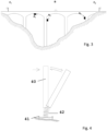
- Figure 3 shows a system according to the present invention that can be provided in combination with detecting units and control units according to the embodiments of figures 1 and 2 .
- A1, A2, An denote the detecting units, while B denotes a control unit and C1 and C2 denote two acoustic/visual signaling units.
- the system is in its configuration required for the monitoring of operative infrastructures such as for example roads, highways, tunnels, bridges, viaducts, dams, support works, public, industrial and civil buildings, towers, monuments, etc.
- operative infrastructures such as for example roads, highways, tunnels, bridges, viaducts, dams, support works, public, industrial and civil buildings, towers, monuments, etc.
- the detecting units monitor the conditions of a bridge.
- the fixing to the structure occurs by means of supports which are made so that to be adapted to cooperate with the characteristics of the infrastructure to be monitored and the construction thereof.
- the box contains measuring sensors, the local control electronics and the transceiver.
- the transceiver is advantageously constituted by a long range radio frequency device for telecommunication.
- the long life driving batteries can be housed inside the same box provided for the sensors and electronics or positioned in a separate box and are connected by cable to the electronics of the detecting unit: a possible external photovoltaic panel with a suitable charge regulator and/or other electric power generating devices can also be present.
- the casings or boxes are concerned, products of the commercial type, such as those for switchboards and/or electronic instruments, can be used.
- the casings are specifically made of plastic or metal materials or a combination of these materials.
- the box containing the instrumentation is preferably shaped and sized so that to allow an adequate protection of the equipment and sensors installed therein.
- control unit and/or signaling units can also be housed in casings made in a similar way as those of the detecting units and by obviously modifying them according to the different requirements provided for the control units and signaling units.
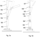
- Figures 4 , 5a and 5b show three variations of a further embodiment of the arrangement of the boxes or casings containing the detecting units.
- the embodiment of figure 4 provides a tubular and elongated shaped case with substantially circular sections having a predefined axial length for each detecting unit.
- This case 40 is constrained to the fixing structure, in this case to the ground by fixing means 41 which connect with the case 40 thanks to an elastic joint 42 with a self-straightening action.
- the self-straightening joint 42 is shown in the form of helical spring, but can advantageously be made like one or more of the embodiments described in the documents IT 0001323688 dated 09/22/2004 IT 001346108 dated 07/03/2008 , IT 0001405009 dated 12/16/2013 , IT 0001405010 dated 12/16/2013 .
- the joint 42 allows the case 40 to always return in the initial position, i.e. in the neutral position in which it is perpendicular to the ground to which it is anchored.
- a self-straightening joint able not only to monitor the acceleration, inclination, etc., and to dampen possible shocks, but also to restore itself, for example after the melting of snow or the transit of debris, can be used in the preferred embodiment.
- the continuous monitoring of the inclination can also provide information on the effective self-straightening conditions after the event.
- Figures 5a and 5b show two variations of a further embodiment in which a plurality of detecting units 50, 51, 52 is concatenated in a sequence of said detecting units thanks to a self-straightening elastic joints 53, 54, 55.
- Each detecting unit can have a combination of sensors comprising for example accelerometer and/or inclinometer sensors and possibly of axial elongation of the joint and/or of rotation around the joint axis and each detecting unit of the succession is displaceable according to the degrees of freedom allowed by the joint with respect to the adjacent units independently from same.
- the construction of the joints and the detecting units can be achieved mutatis mutandis, similarly to one or more of the embodiments described in the documents IT 0001323688 dated 09/22/2004 IT 001346108 dated 07/03/2008 , IT 0001405009 dated 12/16/2013 , IT 0001405010 dated 12/16/2013 , which description is considered part of the present document.
- the elastic joints do not have an essentially cylindrical shape, but are conical and have a lower base larger than the upper one, while the diameters of the joints 56, 56', 56", 56′′′ and those of the casings 50, 51, 52, 57 to which they connect progressively taper with respect to the previous joints and the previous cases.
- This embodiment requires less mechanical energy to bring back the single cases in the aligned standing position.
- FIGS. 5a and 5b are mainly indicated for the monitoring of the snow mantle, also of significant thickness and in avalanche triggering conditions.
- the structures provided with cylindrical joints have high flexibility, but, all sections being equal, less straightening energy with respect to those consisting of conical joints.
- the figures 6 to 8 shown variations of a further embodiment of the invention which can be used when it is necessary to urgently monitor, during an event or after an event, areas subject to high hydrogeological risk (for example avalanches, landslides and floods) and/or in the case in which the site, for safety reasons, cannot be immediately accessed by the technicians in charge of verifying the stability and where it is therefore not possible to fix the monitoring instruments.
- These are particular monitoring structures that can be positioned in the instable mass by helicopter.
- Figure 6 shows a supporting framework 60 of a detecting unit 61, which is shaped like a pyramidal trestle with triangular base.
- the trestle structure can be made of relatively low cost materials, such as Innocenti pipes or similar constructive elements for scaffolding, and supports a highly resistant, watertight container that is able to contain the electronics provided for the detecting unit, the measuring sensors, the data transmission systems (GSM, GPRS, Radio, wireless) together with batteries for the autonomous operation.
- the trestle structure is particularly adapted for the monitoring of avalanches, after the event, and is easily mountable by helicopter without ground personnel. It is also easily achievable on site by mounting the Innocenti pipes.
- the highly resistant container is fixed inside the trestle 60.
- This structure has protruding legs 160, which penetrate the snow mantle, and quickly stabilizes thanks to its shape and weight, also being put in a condition to immediately monitor the movements.
- Figure 7 shows a structure of the tetrapod type denoted by 70, which is provided for being installed by means of drones whenever it is impossible to work safely by helicopter.
- it can be made of steel or of plastic material with reduced weight and dimensions. It is mainly intended to monitor the detachment areas of the avalanche bodies, but it can also be used in landslides. Its particular structure makes it easy to achieve balanced conditions in snow bodies.
- the detecting unit is housed inside the body of the tetrapod 70.
- a hooking ring 71 such as the one provided at the vertex opposite the base of the embodiment of figure 6 , is provided at least at one end of the arms.
- Figure 8 shows a variation of figure 6 , in which the trestle structure 80 is made multiple.
- This configuration is particularly adapted for the after event monitoring of the headland areas of avalanche events having significant transversal development.
- the monitoring instruments i.e. the detecting units 82, can be fixed directly to the tubular elements so that to reconstruct the deformation of the snow mantle along the entire section monitored.
- Figure 9 shows a system according to the present invention which uses units made according to figures 6, 7 and 8 , which are positioned by helicopter or drones.
- the system particularly suited to monitor avalanches during the paroxysmal and after event stage is therefore constituted by:
- the sensors present in the detecting units of the system are directly connected to a communication unit also positioned inside the structure and are configured to communicate in an "intelligent" way only if the quantities monitored by one or more of the single present sensors suffer variations with respect to the preset thresholds for these quantities.
- This new logic has a more immediate management of alarms and allows a considerable reduction in consumptions, therefore in view of a greater autonomy.
- the module can occasionally provide information on its efficiency and consistency state only so that to ensure its constant active monitoring presence.
- the detecting units transmit the data and alarm detections of the various sensors to an external control unit that can be both fixed and movable. This information will therefore be processed by specific software for the automatic displaying of the parameters detected.
- the electronics inside the control unit can transmit, in real time, automatic commands for the alarm signals to one or more acoustic or visual devices.
Landscapes
- Engineering & Computer Science (AREA)
- Physics & Mathematics (AREA)
- General Physics & Mathematics (AREA)
- Aviation & Aerospace Engineering (AREA)
- Computer Networks & Wireless Communication (AREA)
- Testing Or Calibration Of Command Recording Devices (AREA)
- Selective Calling Equipment (AREA)
- Alarm Systems (AREA)
Claims (13)
- System zur Analyse und automatischen Überwachung, ferngesteuert und in Echtzeit, von Strukturen, Infrastrukturen und Berghangsektoren mit hohem hydrogeologischem Risiko, die anfällig für Einstürze, Erdrutsche und/oder Lawinen, im Falle schneller paroxysmaler Ereignisse, mit dem Ziel, die öffentliche oder private Sicherheit zu gewährleisten, umfassend:eine oder mehrere Erfassungseinheiten (A1, A2, A3) mit einem oder mehreren Messsensoren (1, 2, 3) zur Messung eines physikalischen, geologischen, chemischen oder umweltbezogenen Parameters an einem Erfassungspunkt, wobei die Einheit an einem vorbestimmten Erfassungspunkt und vorzugsweise an einer Vielzahl von Erfassungseinheiten positioniert oder positionierbar ist, die jeweils an einem von mehreren über einen Bereich angeordneten Erfassungspunkten positioniert oder positionierbar sind, wobei jede Einheit einen oder mehrere Messsensoren zur Messung eines physikalischen, geologischen, chemischen oder umweltbezogenen Parameters umfasst,dadurch gekennzeichnet, dass das System weiterhin umfasst:mindestens eine Steuereinheit (C1, C2), um Erfassungssignale zu sammeln und diese Signale zumindest teilweise zu verarbeiten oder an einen Remote-Verarbeitungsserver zu übertragen,dass die Erfassungseinheiten und die Steuereinheit mit einer Empfangs- und/oder Sendekommunikationseinheit (7) ausgestattet sind, über die die Erfassungseinheiten und die Steuereinheit miteinander und möglicherweise mit zusätzlichen remoten Client- oder Servereinheiten kommunizieren,und wobei nur wenn eine Änderung von mindestens einem der überwachten Parameter, die sich auf bewegungsbezogene physikalische Größen wie Beschleunigung, Neigung, Bewegungsdistanz und Bewegungsgeschwindigkeit beziehen, und/oder physikalische Parameter wie Temperatur, Feuchtigkeit und Sonnenstrahlung und/oder eine Änderung von mindestens einem der überwachten Parameter, die sich auf chemische Parameter beziehen, auftritt, die Erfassungseinheiten unmittelbar mit der Steuereinheit kommunizieren, die als Aggregator der von der einen oder den mehreren Erfassungseinheiten empfangenen Daten dient, um die Daten zu verarbeiten und auf deren Grundlage die Ausgabe von Signalen zu veranlassen, die den tatsächlichen Bedingungen des überwachten Bereichs entsprechen, indem akustische und/oder visuelle Alarme ausgelöst werden, undwobei die Steuereinheit Signalisierungs- und Warnvorrichtungen umfasst, die wahlweise visueller und/oder akustischer Art oder einer beliebigen Kombination davon sein können,die Erfassungseinheiten mit einer die erfassten Signale der einen oder mehreren Sensoren verarbeitenden Verarbeitungseinheit (5) ausgestattet sind, welche die Variation eines oder mehrerer erfasster Signale im Vergleich zu einem voreingestellten Referenzwert bestimmt und die Aktivierung der Kommunikationseinheit kontrolliert, sodass das erfasste Signal sofort übertragen wird, wenn die Differenz zwischen dem erfassten Signal und dem Referenzsignal einen vorbestimmten, ebenfalls einstellbaren Wert überschreitet, und/oder wenn das Ereignis des Überschreitens eines vorbestimmten, einstellbaren Schwellenwerts für das erfasste Signal eintritt, wobei die genannten Signalisierungs- und Warnvorrichtungen sofort aktiviert werden, undwobei die Empfangs- und/oder Sendekommunikationssektion, über die die Erfassungseinheiten und die Steuereinheit miteinander und möglicherweise mit zusätzlichen remoten Client- oder Servereinheiten kommunizieren, aus drahtlosen Langstrecken-Funkgeräten besteht.
- System nach Anspruch 1, wobei in Kombination mit den Erfassungseinheiten eine Daten- und/oder Steuereingabeeinheit vorgesehen ist, welche durch die Steuereinheit selbst und/oder möglicherweise auch durch eine tragbare Steuereinheit gebildet werden kann, wobei sowohl die stationären als auch die tragbaren Steuereinheiten mit Mensch-Maschine-Schnittstellen versehen sind, um Daten und/oder Steuerungen eingeben und die genannten Schwellenwerte oder Parameter ferngesteuert ändern zu können.
- System nach einem oder mehreren der vorhergehenden Ansprüche, wobei die Erfassungseinheiten zwei oder mehr Sensoren umfassen, die aus allen oder Teilen der Sensoren bestehen können, die aus den folgenden Sensoren ausgewählt sind: Beschleunigungssensoren, Neigungssensoren, Drucksensoren, Temperatursensoren, Positionssensoren, Bewegungssensoren.
- System nach einem oder mehreren der vorangehenden Ansprüche, wobei vorprogrammierte periodische Übertragungen vorgesehen sind, in denen Diagnoseinformationen, beispielsweise über dessen Effizienz und Konsistenzzustand, an die vorgesehene(n) Steuereinheit(en) übermittelt werden, um deren effektiven Betrieb zu überprüfen.
- System nach einem oder mehreren der vorhergehenden Ansprüche, wobei die Erfassungseinheiten ein Gehäuse oder eine Aufnahmebox umfassen, in dem/der nicht nur der/die Sensor(en) und die Sensor-Steuerschaltungen zur Sammlung der Mess- und Verarbeitungssignale untergebracht sind, sondern auch die Empfangs-/Sendesektionen und gegebenenfalls die Antriebsbatterie, die gegebenenfalls in einem separaten Gehäuse vorgesehen sein kann, das über Kabel mit dem die Sensoren enthaltenden Gehäuse verbunden werden kann.
- System nach einem oder mehreren der vorhergehenden Ansprüche, wobei elektrische Energieerzeugungssysteme, wie beispielsweise Photovoltaikpaneele, Mikroturbinengeneratoren oder Ähnliches, vorgesehen sind.
- System nach Anspruch 5 oder 6, wobei die Gehäuse integrierte oder damit koppelbare Befestigungselemente aufweisen, die zur Befestigung an den in den Installationspunkten befindlichen Strukturen bestimmt sind, wie zum Beispiel integrierte oder abnehmbar befestigbare Bügel, die dazu bestimmt sind, in eine Wand eingebettet zu werden, und durch Dübel oder Nägel oder Pfähle an diesen Strukturen befestigt werden.
- System nach einem der Ansprüche 5 bis 7, wobei das zur Unterbringung sowohl des Sensors/der Sensoren als auch der Hardware der Erfassungseinheiten dienende Gehäuse, wie oben beschrieben, entweder mit einem Befestigungsorgan oder einer Befestigungsstruktur mittels eines flexiblen Elements verbunden ist, das zwischen dem Befestigungselement und/oder der Befestigungsstruktur und dem Gehäuse der Erfassungseinheit angeordnet ist, wobei das flexible Element als selbstausrichtendes Gelenk ausgebildet ist.
- System nach Anspruch 8, wobei das selbstausrichtende Gelenk in Kombination mit einem oder mehreren der folgenden Sensoren vorgesehen ist: Beschleunigungs-, Neigungs-, Druck-, Temperatur-, Positions- und Bewegungssensoren.
- System nach einem der Ansprüche 5 bis 9, wobei eine Vielzahl von Erfassungseinheiten mit ihren eigenen Sensoren vorgesehen sind, und zwar mindestens Beschleunigungssensoren, Sensoren für die relative Position zwischen verschiedenen Erfassungseinheiten und/oder Neigungssensoren und/oder andere Sensoren, wobei die Erfassungseinheiten nacheinander mittels eines selbstausrichtenden elastischen Gelenks verkettet sind, das zwischen jedem von zwei aufeinanderfolgenden Gehäusen von zwei Erfassungseinheiten und zwischen einem ersten Gehäuse einer an die Befestigungsstruktur und/oder das Befestigungselement angrenzenden ersten Erfassungseinheit, zwischen der Box und der Befestigungsstruktur oder dem Befestigungsorgan angeordnet ist.
- System nach einem der Ansprüche 5 bis 10, wobei das Gehäuse rohrförmig und in Richtung seiner Mittelachse langgestreckt ist, wobei auch die elastischen Gelenke in neutraler Position in einer Linie mit den rohrförmigen Gehäusen ausgerichtet sind und Bewegungen in Form von zumindest einer seitlichen Neigung und/oder einer Längung und/oder einer Drehung um ihre eigene Achse parallel zur Längungsrichtung ausführen können, wobei in Kombination mit dem Gelenk die miteinander verkettete(n) Erfassungseinheit(en) mit mindestens einem Sensor zum Messen der Bewegung der Erfassungseinheit(en) in Bezug auf die Befestigungsstruktur und/oder in Bezug aufeinander, vorzugsweise entlang eines oder mehrerer Freiheitsgrade, vorzugsweise entlang aller vorgesehenen Freiheitsgrade, versehen sind.
- System nach einem der Ansprüche 8 bis 11, wobei die Gelenke vom zylindrischen oder konischen Typ sein können und sich in Bezug auf die Verbindung zwischen den Gehäusen der unterliegenden Erfassungseinheiten allmählich verjüngen.
- System nach einem oder mehreren der vorhergehenden Ansprüche, wobei eine oder mehrere Erfassungseinheiten in einem bockförmigen Gestell oder Tetrapod oder Mehrfachbock montiert sind, dessen Schwerpunkt in Richtung der durch die auseinanderlaufenden Enden des bockförmigen Gestells oder Tetrapods oder Mehrfachbocks bestimmten Auflagebasis abgesenkt ist und innerhalb dessen, d.h. in dem Raum, der durch die von den Ständern und Querstreben des Gestells oder Tetrapods definierten idealen Hüllflächen definiert ist, eine oder mehrere Erfassungseinheiten gelagert sind.
Applications Claiming Priority (1)
| Application Number | Priority Date | Filing Date | Title |
|---|---|---|---|
| IT201800002465A IT201800002465A1 (it) | 2018-02-07 | 2018-02-07 | Sistema per il monitoraggio automatico wireless da remoto e in tempo reale di strutture, infrastrutture e settori di versante ad elevato rischio idrogeologico finalizzato alla salvaguardia della pubblica e privata incolumità |
Publications (3)
| Publication Number | Publication Date |
|---|---|
| EP3524948A1 EP3524948A1 (de) | 2019-08-14 |
| EP3524948B1 true EP3524948B1 (de) | 2024-01-31 |
| EP3524948C0 EP3524948C0 (de) | 2024-01-31 |
Family
ID=62386660
Family Applications (1)
| Application Number | Title | Priority Date | Filing Date |
|---|---|---|---|
| EP19155241.3A Active EP3524948B1 (de) | 2018-02-07 | 2019-02-04 | System zur automatischen drahtlosen überwachung, ferngesteuert und in echtzeit, von strukturen, infrastrukturen und berghangsektoren |
Country Status (2)
| Country | Link |
|---|---|
| EP (1) | EP3524948B1 (de) |
| IT (1) | IT201800002465A1 (de) |
Families Citing this family (14)
| Publication number | Priority date | Publication date | Assignee | Title |
|---|---|---|---|---|
| CN110597149B (zh) * | 2019-10-10 | 2024-05-07 | 中国地质环境监测院 | 一种交互式耦合多维度智能崩塌落石监测系统及方法 |
| CN110660196A (zh) * | 2019-11-25 | 2020-01-07 | 中国地质调查局水文地质环境地质调查中心 | 一种基于LoRa自组网的高陡岩溶山体变形监测装置及方法 |
| CN111627279B (zh) * | 2020-05-19 | 2022-10-11 | 中国安全生产科学研究院 | 一种模拟滑坡泥石流灾害链全过程的试验系统 |
| DE102020122861A1 (de) | 2020-09-01 | 2022-03-03 | Geobrugg Ag | Sensornetzwerkbasiertes Analyse- und/oder Vorhersageverfahren und Fernüberwachungssensorvorrichtung |
| CN112129355A (zh) * | 2020-10-29 | 2020-12-25 | 深圳市物联升科技有限公司 | 一种地质土木工程监测装置 |
| CN112398070A (zh) * | 2021-01-06 | 2021-02-23 | 南京家洁馨商贸有限公司 | 一种山区防滑坡数据电缆保护装置 |
| IT202100016109A1 (it) * | 2021-06-21 | 2022-12-21 | Agon Srls | Sistema per il monitoraggio di fenomeni franosi |
| CN113701712B (zh) * | 2021-08-09 | 2024-02-02 | 广州建设工程质量安全检测中心有限公司 | 一种检测桥梁与支座脱空时主梁倾斜度的方法及装置 |
| CN114295091B (zh) * | 2021-12-30 | 2024-04-02 | 北京源清慧虹信息科技有限公司 | 柔性测斜传感器及方位标记方法 |
| CN114926961B (zh) * | 2022-05-16 | 2024-02-27 | 桂林理工大学 | 一种适用于含断层岩质边坡的滑坡检测预警装置和方法 |
| AT527332B1 (de) * | 2023-06-28 | 2025-08-15 | Weingarth Steve | Steinschlag- und lawinenfrühwarnsystem |
| CN116772709A (zh) * | 2023-06-29 | 2023-09-19 | 山东黄金矿业科技有限公司充填工程实验室分公司 | 一种下向进路充填材料形变及水热演变监测方法 |
| AT527690B1 (de) * | 2023-11-13 | 2025-06-15 | Bladescape Airborne Services Gmbh | Sensoranordnung und Verfahren |
| CN118654732B (zh) * | 2024-08-16 | 2024-11-05 | 北京致感科技有限公司 | 基于传感器融合的岩土层结构变化监测方法及系统 |
Citations (1)
| Publication number | Priority date | Publication date | Assignee | Title |
|---|---|---|---|---|
| JPH11118937A (ja) * | 1997-10-09 | 1999-04-30 | Mitsubishi Heavy Ind Ltd | 地震データ伝送方法及び地震データ伝送機能付き地震計 |
Family Cites Families (4)
| Publication number | Priority date | Publication date | Assignee | Title |
|---|---|---|---|---|
| US6292108B1 (en) * | 1997-09-04 | 2001-09-18 | The Board Of Trustees Of The Leland Standford Junior University | Modular, wireless damage monitoring system for structures |
| ITBO20070756A1 (it) * | 2007-11-16 | 2009-05-17 | Filippo Bastianini | Dispositivo per il monitoraggio dello stato di salute di strutture |
| WO2011160694A1 (en) * | 2010-06-24 | 2011-12-29 | Abb Research Ltd | A method in a wireless process control system for reducing power consumption, and a controller and computer program products |
| ITUA20163182A1 (it) * | 2016-05-05 | 2017-11-05 | C S G S R L | Dispositivo per il monitoraggio 2D/3D di parametri geotecnici, geologici-strutturali, idrogeologici e geofisici di terreni, rocce e strutture in genere |
-
2018
- 2018-02-07 IT IT201800002465A patent/IT201800002465A1/it unknown
-
2019
- 2019-02-04 EP EP19155241.3A patent/EP3524948B1/de active Active
Patent Citations (1)
| Publication number | Priority date | Publication date | Assignee | Title |
|---|---|---|---|---|
| JPH11118937A (ja) * | 1997-10-09 | 1999-04-30 | Mitsubishi Heavy Ind Ltd | 地震データ伝送方法及び地震データ伝送機能付き地震計 |
Also Published As
| Publication number | Publication date |
|---|---|
| IT201800002465A1 (it) | 2019-08-07 |
| EP3524948C0 (de) | 2024-01-31 |
| EP3524948A1 (de) | 2019-08-14 |
Similar Documents
| Publication | Publication Date | Title |
|---|---|---|
| EP3524948B1 (de) | System zur automatischen drahtlosen überwachung, ferngesteuert und in echtzeit, von strukturen, infrastrukturen und berghangsektoren | |
| JP7805414B2 (ja) | 水文地質学的リスクを監視するためのシステムおよび方法 | |
| CN102163363B (zh) | 山体滑坡实时监测与预警系统 | |
| RU2630334C2 (ru) | Система динамического контроля отделения кровли выработки на основе волоконных решеток и способ предварительного оповещения | |
| KR20120139891A (ko) | 기울기 센서가 설치된 구조물 및 구조물 기울기 원격 측정 시스템 | |
| CN205209475U (zh) | 串联式序列节段变形监测传感装置 | |
| CN103996269A (zh) | 无线数据采集控制系统 | |
| CN110264673A (zh) | 一种集成gnss和微震信息的多功能地灾监测装置及系统 | |
| CN106600911A (zh) | 脚手架安全监视预警系统 | |
| CN204457878U (zh) | 无线缆、可长期独立工作的滑坡灾害监测预警系统 | |
| KR102036212B1 (ko) | Iot를 이용한 비탈면 모니터링 장치 | |
| KR102103509B1 (ko) | 면진형 전력변환장치의 지진 대응 시스템 및 방법 | |
| CN106033637A (zh) | 无线缆、可长期独立工作的滑坡灾害监测预警方法及系统 | |
| KR20170004206A (ko) | 대상물 위험 알림 시스템 | |
| CN111693039A (zh) | 根石状态感知监测系统及其监测方法 | |
| CN113865650A (zh) | 护岸抛石稳定性监测系统及其监测方法 | |
| JP2002312868A (ja) | 土砂災害センサ及び土砂災害監視システム | |
| CN210466680U (zh) | 一种集成gnss和微震信息的多功能地灾监测装置及系统 | |
| CN203849835U (zh) | 无线数据采集控制系统 | |
| JP2008140178A (ja) | 構造物の監視システムおよび構造物の監視方法 | |
| CN107248264A (zh) | 一种泥石流预警器以及预警方法 | |
| CN105157553A (zh) | 建筑物构件相对位移信号传感发生装置及其使用方法 | |
| CN206907199U (zh) | 一种泥石流预警器 | |
| JP2016200417A (ja) | 変位量計測システム及び変位計 | |
| CN221040207U (zh) | 一种岩溶塌陷预警装置 |
Legal Events
| Date | Code | Title | Description |
|---|---|---|---|
| PUAI | Public reference made under article 153(3) epc to a published international application that has entered the european phase |
Free format text: ORIGINAL CODE: 0009012 |
|
| STAA | Information on the status of an ep patent application or granted ep patent |
Free format text: STATUS: THE APPLICATION HAS BEEN PUBLISHED |
|
| AK | Designated contracting states |
Kind code of ref document: A1 Designated state(s): AL AT BE BG CH CY CZ DE DK EE ES FI FR GB GR HR HU IE IS IT LI LT LU LV MC MK MT NL NO PL PT RO RS SE SI SK SM TR |
|
| AX | Request for extension of the european patent |
Extension state: BA ME |
|
| STAA | Information on the status of an ep patent application or granted ep patent |
Free format text: STATUS: REQUEST FOR EXAMINATION WAS MADE |
|
| 17P | Request for examination filed |
Effective date: 20200213 |
|
| RBV | Designated contracting states (corrected) |
Designated state(s): AL AT BE BG CH CY CZ DE DK EE ES FI FR GB GR HR HU IE IS IT LI LT LU LV MC MK MT NL NO PL PT RO RS SE SI SK SM TR |
|
| STAA | Information on the status of an ep patent application or granted ep patent |
Free format text: STATUS: EXAMINATION IS IN PROGRESS |
|
| 17Q | First examination report despatched |
Effective date: 20200930 |
|
| GRAP | Despatch of communication of intention to grant a patent |
Free format text: ORIGINAL CODE: EPIDOSNIGR1 |
|
| STAA | Information on the status of an ep patent application or granted ep patent |
Free format text: STATUS: GRANT OF PATENT IS INTENDED |
|
| RIC1 | Information provided on ipc code assigned before grant |
Ipc: H04Q 9/00 20060101ALI20230717BHEP Ipc: G01M 5/00 20060101ALI20230717BHEP Ipc: G01K 1/024 20210101ALI20230717BHEP Ipc: G01K 1/02 20060101AFI20230717BHEP |
|
| INTG | Intention to grant announced |
Effective date: 20230821 |
|
| GRAS | Grant fee paid |
Free format text: ORIGINAL CODE: EPIDOSNIGR3 |
|
| GRAA | (expected) grant |
Free format text: ORIGINAL CODE: 0009210 |
|
| STAA | Information on the status of an ep patent application or granted ep patent |
Free format text: STATUS: THE PATENT HAS BEEN GRANTED |
|
| AK | Designated contracting states |
Kind code of ref document: B1 Designated state(s): AL AT BE BG CH CY CZ DE DK EE ES FI FR GB GR HR HU IE IS IT LI LT LU LV MC MK MT NL NO PL PT RO RS SE SI SK SM TR |
|
| REG | Reference to a national code |
Ref country code: GB Ref legal event code: FG4D Ref country code: CH Ref legal event code: EP |
|
| REG | Reference to a national code |
Ref country code: DE Ref legal event code: R096 Ref document number: 602019045871 Country of ref document: DE |
|
| REG | Reference to a national code |
Ref country code: IE Ref legal event code: FG4D |
|
| U01 | Request for unitary effect filed |
Effective date: 20240220 |
|
| U07 | Unitary effect registered |
Designated state(s): AT BE BG DE DK EE FI FR IT LT LU LV MT NL PT SE SI Effective date: 20240229 |
|
| U20 | Renewal fee for the european patent with unitary effect paid |
Year of fee payment: 6 Effective date: 20240226 |
|
| REG | Reference to a national code |
Ref country code: LT Ref legal event code: MG9D |
|
| PG25 | Lapsed in a contracting state [announced via postgrant information from national office to epo] |
Ref country code: IS Free format text: LAPSE BECAUSE OF FAILURE TO SUBMIT A TRANSLATION OF THE DESCRIPTION OR TO PAY THE FEE WITHIN THE PRESCRIBED TIME-LIMIT Effective date: 20240531 |
|
| PG25 | Lapsed in a contracting state [announced via postgrant information from national office to epo] |
Ref country code: GR Free format text: LAPSE BECAUSE OF FAILURE TO SUBMIT A TRANSLATION OF THE DESCRIPTION OR TO PAY THE FEE WITHIN THE PRESCRIBED TIME-LIMIT Effective date: 20240501 |
|
| PG25 | Lapsed in a contracting state [announced via postgrant information from national office to epo] |
Ref country code: RS Free format text: LAPSE BECAUSE OF FAILURE TO SUBMIT A TRANSLATION OF THE DESCRIPTION OR TO PAY THE FEE WITHIN THE PRESCRIBED TIME-LIMIT Effective date: 20240430 Ref country code: HR Free format text: LAPSE BECAUSE OF FAILURE TO SUBMIT A TRANSLATION OF THE DESCRIPTION OR TO PAY THE FEE WITHIN THE PRESCRIBED TIME-LIMIT Effective date: 20240131 |
|
| PG25 | Lapsed in a contracting state [announced via postgrant information from national office to epo] |
Ref country code: ES Free format text: LAPSE BECAUSE OF FAILURE TO SUBMIT A TRANSLATION OF THE DESCRIPTION OR TO PAY THE FEE WITHIN THE PRESCRIBED TIME-LIMIT Effective date: 20240131 |
|
| PG25 | Lapsed in a contracting state [announced via postgrant information from national office to epo] |
Ref country code: RS Free format text: LAPSE BECAUSE OF FAILURE TO SUBMIT A TRANSLATION OF THE DESCRIPTION OR TO PAY THE FEE WITHIN THE PRESCRIBED TIME-LIMIT Effective date: 20240430 Ref country code: IS Free format text: LAPSE BECAUSE OF FAILURE TO SUBMIT A TRANSLATION OF THE DESCRIPTION OR TO PAY THE FEE WITHIN THE PRESCRIBED TIME-LIMIT Effective date: 20240531 Ref country code: HR Free format text: LAPSE BECAUSE OF FAILURE TO SUBMIT A TRANSLATION OF THE DESCRIPTION OR TO PAY THE FEE WITHIN THE PRESCRIBED TIME-LIMIT Effective date: 20240131 Ref country code: GR Free format text: LAPSE BECAUSE OF FAILURE TO SUBMIT A TRANSLATION OF THE DESCRIPTION OR TO PAY THE FEE WITHIN THE PRESCRIBED TIME-LIMIT Effective date: 20240501 Ref country code: ES Free format text: LAPSE BECAUSE OF FAILURE TO SUBMIT A TRANSLATION OF THE DESCRIPTION OR TO PAY THE FEE WITHIN THE PRESCRIBED TIME-LIMIT Effective date: 20240131 |
|
| PG25 | Lapsed in a contracting state [announced via postgrant information from national office to epo] |
Ref country code: PL Free format text: LAPSE BECAUSE OF FAILURE TO SUBMIT A TRANSLATION OF THE DESCRIPTION OR TO PAY THE FEE WITHIN THE PRESCRIBED TIME-LIMIT Effective date: 20240131 |
|
| PG25 | Lapsed in a contracting state [announced via postgrant information from national office to epo] |
Ref country code: PL Free format text: LAPSE BECAUSE OF FAILURE TO SUBMIT A TRANSLATION OF THE DESCRIPTION OR TO PAY THE FEE WITHIN THE PRESCRIBED TIME-LIMIT Effective date: 20240131 |
|
| PG25 | Lapsed in a contracting state [announced via postgrant information from national office to epo] |
Ref country code: SM Free format text: LAPSE BECAUSE OF FAILURE TO SUBMIT A TRANSLATION OF THE DESCRIPTION OR TO PAY THE FEE WITHIN THE PRESCRIBED TIME-LIMIT Effective date: 20240131 |
|
| PG25 | Lapsed in a contracting state [announced via postgrant information from national office to epo] |
Ref country code: CZ Free format text: LAPSE BECAUSE OF FAILURE TO SUBMIT A TRANSLATION OF THE DESCRIPTION OR TO PAY THE FEE WITHIN THE PRESCRIBED TIME-LIMIT Effective date: 20240131 |
|
| PG25 | Lapsed in a contracting state [announced via postgrant information from national office to epo] |
Ref country code: SK Free format text: LAPSE BECAUSE OF FAILURE TO SUBMIT A TRANSLATION OF THE DESCRIPTION OR TO PAY THE FEE WITHIN THE PRESCRIBED TIME-LIMIT Effective date: 20240131 |
|
| PG25 | Lapsed in a contracting state [announced via postgrant information from national office to epo] |
Ref country code: SM Free format text: LAPSE BECAUSE OF FAILURE TO SUBMIT A TRANSLATION OF THE DESCRIPTION OR TO PAY THE FEE WITHIN THE PRESCRIBED TIME-LIMIT Effective date: 20240131 Ref country code: SK Free format text: LAPSE BECAUSE OF FAILURE TO SUBMIT A TRANSLATION OF THE DESCRIPTION OR TO PAY THE FEE WITHIN THE PRESCRIBED TIME-LIMIT Effective date: 20240131 Ref country code: RO Free format text: LAPSE BECAUSE OF FAILURE TO SUBMIT A TRANSLATION OF THE DESCRIPTION OR TO PAY THE FEE WITHIN THE PRESCRIBED TIME-LIMIT Effective date: 20240131 Ref country code: CZ Free format text: LAPSE BECAUSE OF FAILURE TO SUBMIT A TRANSLATION OF THE DESCRIPTION OR TO PAY THE FEE WITHIN THE PRESCRIBED TIME-LIMIT Effective date: 20240131 |
|
| REG | Reference to a national code |
Ref country code: DE Ref legal event code: R097 Ref document number: 602019045871 Country of ref document: DE |
|
| PG25 | Lapsed in a contracting state [announced via postgrant information from national office to epo] |
Ref country code: MC Free format text: LAPSE BECAUSE OF FAILURE TO SUBMIT A TRANSLATION OF THE DESCRIPTION OR TO PAY THE FEE WITHIN THE PRESCRIBED TIME-LIMIT Effective date: 20240131 |
|
| PG25 | Lapsed in a contracting state [announced via postgrant information from national office to epo] |
Ref country code: MC Free format text: LAPSE BECAUSE OF FAILURE TO SUBMIT A TRANSLATION OF THE DESCRIPTION OR TO PAY THE FEE WITHIN THE PRESCRIBED TIME-LIMIT Effective date: 20240131 |
|
| PLBE | No opposition filed within time limit |
Free format text: ORIGINAL CODE: 0009261 |
|
| STAA | Information on the status of an ep patent application or granted ep patent |
Free format text: STATUS: NO OPPOSITION FILED WITHIN TIME LIMIT |
|
| 26N | No opposition filed |
Effective date: 20241101 |
|
| PG25 | Lapsed in a contracting state [announced via postgrant information from national office to epo] |
Ref country code: IE Free format text: LAPSE BECAUSE OF NON-PAYMENT OF DUE FEES Effective date: 20240204 |
|
| PG25 | Lapsed in a contracting state [announced via postgrant information from national office to epo] |
Ref country code: IE Free format text: LAPSE BECAUSE OF NON-PAYMENT OF DUE FEES Effective date: 20240204 |
|
| U20 | Renewal fee for the european patent with unitary effect paid |
Year of fee payment: 7 Effective date: 20250212 |
|
| PG25 | Lapsed in a contracting state [announced via postgrant information from national office to epo] |
Ref country code: CY Free format text: LAPSE BECAUSE OF FAILURE TO SUBMIT A TRANSLATION OF THE DESCRIPTION OR TO PAY THE FEE WITHIN THE PRESCRIBED TIME-LIMIT; INVALID AB INITIO Effective date: 20190204 |
|
| PG25 | Lapsed in a contracting state [announced via postgrant information from national office to epo] |
Ref country code: HU Free format text: LAPSE BECAUSE OF FAILURE TO SUBMIT A TRANSLATION OF THE DESCRIPTION OR TO PAY THE FEE WITHIN THE PRESCRIBED TIME-LIMIT; INVALID AB INITIO Effective date: 20190204 |
|
| PG25 | Lapsed in a contracting state [announced via postgrant information from national office to epo] |
Ref country code: TR Free format text: LAPSE BECAUSE OF FAILURE TO SUBMIT A TRANSLATION OF THE DESCRIPTION OR TO PAY THE FEE WITHIN THE PRESCRIBED TIME-LIMIT Effective date: 20240131 |
|
| REG | Reference to a national code |
Ref country code: CH Ref legal event code: U11 Free format text: ST27 STATUS EVENT CODE: U-0-0-U10-U11 (AS PROVIDED BY THE NATIONAL OFFICE) Effective date: 20260301 |
|
| U20 | Renewal fee for the european patent with unitary effect paid |
Year of fee payment: 8 Effective date: 20260127 |
|
| PGFP | Annual fee paid to national office [announced via postgrant information from national office to epo] |
Ref country code: GB Payment date: 20260128 Year of fee payment: 8 |
|
| PGFP | Annual fee paid to national office [announced via postgrant information from national office to epo] |
Ref country code: NO Payment date: 20260130 Year of fee payment: 8 |
|
| PGFP | Annual fee paid to national office [announced via postgrant information from national office to epo] |
Ref country code: CH Payment date: 20260301 Year of fee payment: 8 |