EP3829772B1 - Vorrichtung und verfahren zur verbesserten erzrückgewinnung - Google Patents
Vorrichtung und verfahren zur verbesserten erzrückgewinnung Download PDFInfo
- Publication number
- EP3829772B1 EP3829772B1 EP19843887.1A EP19843887A EP3829772B1 EP 3829772 B1 EP3829772 B1 EP 3829772B1 EP 19843887 A EP19843887 A EP 19843887A EP 3829772 B1 EP3829772 B1 EP 3829772B1
- Authority
- EP
- European Patent Office
- Prior art keywords
- stage
- magnetic
- flotation
- recovery
- gauss
- Prior art date
- Legal status (The legal status is an assumption and is not a legal conclusion. Google has not performed a legal analysis and makes no representation as to the accuracy of the status listed.)
- Active
Links
Images






Classifications
-
- B—PERFORMING OPERATIONS; TRANSPORTING
- B03—SEPARATION OF SOLID MATERIALS USING LIQUIDS OR USING PNEUMATIC TABLES OR JIGS; MAGNETIC OR ELECTROSTATIC SEPARATION OF SOLID MATERIALS FROM SOLID MATERIALS OR FLUIDS; SEPARATION BY HIGH-VOLTAGE ELECTRIC FIELDS
- B03C—MAGNETIC OR ELECTROSTATIC SEPARATION OF SOLID MATERIALS FROM SOLID MATERIALS OR FLUIDS; SEPARATION BY HIGH-VOLTAGE ELECTRIC FIELDS
- B03C1/00—Magnetic separation
- B03C1/02—Magnetic separation acting directly on the substance being separated
- B03C1/025—High gradient magnetic separators
-
- B—PERFORMING OPERATIONS; TRANSPORTING
- B03—SEPARATION OF SOLID MATERIALS USING LIQUIDS OR USING PNEUMATIC TABLES OR JIGS; MAGNETIC OR ELECTROSTATIC SEPARATION OF SOLID MATERIALS FROM SOLID MATERIALS OR FLUIDS; SEPARATION BY HIGH-VOLTAGE ELECTRIC FIELDS
- B03C—MAGNETIC OR ELECTROSTATIC SEPARATION OF SOLID MATERIALS FROM SOLID MATERIALS OR FLUIDS; SEPARATION BY HIGH-VOLTAGE ELECTRIC FIELDS
- B03C1/00—Magnetic separation
- B03C1/02—Magnetic separation acting directly on the substance being separated
- B03C1/025—High gradient magnetic separators
- B03C1/031—Component parts; Auxiliary operations
- B03C1/033—Component parts; Auxiliary operations characterised by the magnetic circuit
- B03C1/0332—Component parts; Auxiliary operations characterised by the magnetic circuit using permanent magnets
-
- B—PERFORMING OPERATIONS; TRANSPORTING
- B03—SEPARATION OF SOLID MATERIALS USING LIQUIDS OR USING PNEUMATIC TABLES OR JIGS; MAGNETIC OR ELECTROSTATIC SEPARATION OF SOLID MATERIALS FROM SOLID MATERIALS OR FLUIDS; SEPARATION BY HIGH-VOLTAGE ELECTRIC FIELDS
- B03C—MAGNETIC OR ELECTROSTATIC SEPARATION OF SOLID MATERIALS FROM SOLID MATERIALS OR FLUIDS; SEPARATION BY HIGH-VOLTAGE ELECTRIC FIELDS
- B03C1/00—Magnetic separation
- B03C1/02—Magnetic separation acting directly on the substance being separated
-
- B—PERFORMING OPERATIONS; TRANSPORTING
- B03—SEPARATION OF SOLID MATERIALS USING LIQUIDS OR USING PNEUMATIC TABLES OR JIGS; MAGNETIC OR ELECTROSTATIC SEPARATION OF SOLID MATERIALS FROM SOLID MATERIALS OR FLUIDS; SEPARATION BY HIGH-VOLTAGE ELECTRIC FIELDS
- B03C—MAGNETIC OR ELECTROSTATIC SEPARATION OF SOLID MATERIALS FROM SOLID MATERIALS OR FLUIDS; SEPARATION BY HIGH-VOLTAGE ELECTRIC FIELDS
- B03C1/00—Magnetic separation
- B03C1/02—Magnetic separation acting directly on the substance being separated
- B03C1/025—High gradient magnetic separators
- B03C1/031—Component parts; Auxiliary operations
-
- B—PERFORMING OPERATIONS; TRANSPORTING
- B03—SEPARATION OF SOLID MATERIALS USING LIQUIDS OR USING PNEUMATIC TABLES OR JIGS; MAGNETIC OR ELECTROSTATIC SEPARATION OF SOLID MATERIALS FROM SOLID MATERIALS OR FLUIDS; SEPARATION BY HIGH-VOLTAGE ELECTRIC FIELDS
- B03C—MAGNETIC OR ELECTROSTATIC SEPARATION OF SOLID MATERIALS FROM SOLID MATERIALS OR FLUIDS; SEPARATION BY HIGH-VOLTAGE ELECTRIC FIELDS
- B03C1/00—Magnetic separation
- B03C1/02—Magnetic separation acting directly on the substance being separated
- B03C1/28—Magnetic plugs and dipsticks
- B03C1/286—Magnetic plugs and dipsticks disposed at the inner circumference of a recipient, e.g. magnetic drain bolt
-
- B—PERFORMING OPERATIONS; TRANSPORTING
- B03—SEPARATION OF SOLID MATERIALS USING LIQUIDS OR USING PNEUMATIC TABLES OR JIGS; MAGNETIC OR ELECTROSTATIC SEPARATION OF SOLID MATERIALS FROM SOLID MATERIALS OR FLUIDS; SEPARATION BY HIGH-VOLTAGE ELECTRIC FIELDS
- B03C—MAGNETIC OR ELECTROSTATIC SEPARATION OF SOLID MATERIALS FROM SOLID MATERIALS OR FLUIDS; SEPARATION BY HIGH-VOLTAGE ELECTRIC FIELDS
- B03C1/00—Magnetic separation
- B03C1/02—Magnetic separation acting directly on the substance being separated
- B03C1/30—Combinations with other devices, not otherwise provided for
-
- B—PERFORMING OPERATIONS; TRANSPORTING
- B03—SEPARATION OF SOLID MATERIALS USING LIQUIDS OR USING PNEUMATIC TABLES OR JIGS; MAGNETIC OR ELECTROSTATIC SEPARATION OF SOLID MATERIALS FROM SOLID MATERIALS OR FLUIDS; SEPARATION BY HIGH-VOLTAGE ELECTRIC FIELDS
- B03D—FLOTATION; DIFFERENTIAL SEDIMENTATION
- B03D1/00—Flotation
-
- B—PERFORMING OPERATIONS; TRANSPORTING
- B03—SEPARATION OF SOLID MATERIALS USING LIQUIDS OR USING PNEUMATIC TABLES OR JIGS; MAGNETIC OR ELECTROSTATIC SEPARATION OF SOLID MATERIALS FROM SOLID MATERIALS OR FLUIDS; SEPARATION BY HIGH-VOLTAGE ELECTRIC FIELDS
- B03D—FLOTATION; DIFFERENTIAL SEDIMENTATION
- B03D1/00—Flotation
- B03D1/02—Froth-flotation processes
-
- B—PERFORMING OPERATIONS; TRANSPORTING
- B03—SEPARATION OF SOLID MATERIALS USING LIQUIDS OR USING PNEUMATIC TABLES OR JIGS; MAGNETIC OR ELECTROSTATIC SEPARATION OF SOLID MATERIALS FROM SOLID MATERIALS OR FLUIDS; SEPARATION BY HIGH-VOLTAGE ELECTRIC FIELDS
- B03C—MAGNETIC OR ELECTROSTATIC SEPARATION OF SOLID MATERIALS FROM SOLID MATERIALS OR FLUIDS; SEPARATION BY HIGH-VOLTAGE ELECTRIC FIELDS
- B03C2201/00—Details of magnetic or electrostatic separation
- B03C2201/18—Magnetic separation whereby the particles are suspended in a liquid
Definitions
- the present invention relates to apparatus and process for improved ore recovery and more particularly to an apparatus and process which improves the recovery from mineral fines.
- Mineral processing plants also have other separation processes downstream of flotation that may be inefficient in removing ⁇ 8 ⁇ m mineral from the process.
- dewatering processes - the settling (or thickening) then filtration of the flotation concentrate and the thickening of the flotation tailings.
- the water recovered from these dewatering processes report back to the grinding circuit or other parts of the process upstream of the flotation.
- dewatering processes are not 100% efficient so the process water does retain some of the finer mineral. Filter cloth manufacturers claim only 95% recovery of ⁇ 4 ⁇ m minerals when concentrate is being filtered.
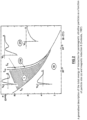
- Magnetic conditioning has been in use in plants for many years. There is a relationship between magnetic field strength and the size of particle that can be aggregated. This can be seen in Figure 2 from Svoboda, 1987.As magnetic field strength (B) increases smaller paramagnetic particles can be aggregated.
- Figure 2 depicts a generalised description of the total energy of interaction for paramagnetic ultrafine particles as a function of particle size (a) and magnetic induction B (Svoboda, 1987).
- Fine Mineral means ore particles after grinding or other processing step in the size range predominantly between zero and substantially 38 ⁇ m and more preferably between zero and substantially 25 ⁇ m.
- An object of the invention is a method of increasing recovery of a metal portion from a predetermined quantity of ore in a flotation recovery circuit which comprises a grinding stage, a flotation recovery stage, a dewatering stage and a filter stage according to claim 1.
- Another object of the invention is a system for increasing recovery of a metal portion from a predetermined quantity of ore in a flotation recovery circuit which comprises a grinding stage, a flotation recovery stage according to claim 8.
- Preferred embodiments are the subject-matter of dependent claims.
- the ⁇ 8-10 ⁇ m mineral remains ⁇ 8-10 ⁇ m, is not filtered out from the process stream and so not detected in the plant.
- the mineral is there but because it is not aggregated it is not filtered and therefore not detected.
- the aggregating of the ⁇ 8-10 ⁇ m mineral to a filterable >8-10 ⁇ m with magnetic conditioning may increase the filtration and detection of fine mineral in its UPSTREAM process.
- Embodiments of the invention relate to using stronger magnetic fields to carry out magnetic conditioning in a flotation recovery circuit which returns recovered process water to the grinding stage and in so doing not only impacting the flotation recovery but the magnetic conditioning of the flotation circuit also impacting a surprising change in the UPSTREAM feed grade due to magnetic conditioning.
- the apparatus illustrated and described with reference to Figs 4 to 7 may be located in the magnetic conditioning stage 40 illustrated in the process diagram of Figure 3 .
- the apparatus causes the magnetic source 10 to apply an increased range of magnetic field strength to the ground ore portion during this stage thereby to cause increased recovery by improved recovery at the flotation stage 31 arising from the increased range of magnetic field strength; the process interacting with the recovered process water in which the ground ore portion is contained.
- the magnetic field strength applied is at least 4500 Gauss. More preferably the magnetic field strength is at the range of 4500 to 10000 Gauss. More preferably, the magnetic field strength is in the range of 5000 to 10000 Gauss.
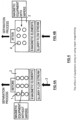
- Figures 4A, 4B illustrates the effect of equipment sizing on using wiper magnetising.
- the magnet may be deactivated for 25%-35% of the time to clean the magnet.
- this invention because deactivation of the magnetic source does not occur, the number of magnetic sources can be reduced by 25%-35%.
- Figures 4A shows an arrangement of magnetic sources 1 in an array within a predetermined treatment volume 2.
- Figure 4B illustrates the same predetermined treatment volume 2 this time with magnetic sources 4 having associated therewith wipers (refer later description) which mechanically clean the exterior of the sources 4 whilst the sources 4 are retained within the flowstream 3 on a continuous basis.
- wipers wipers
- a wiping mechanism to wipe off the build-up of the ferromagnetic minerals.
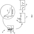
- This preferred method with reference to Figures 4A, 4B , 5 , 6 works by the magnetic source 10 being housed in a stainless steel housing 11 with a very thin abrasion resistant rubber lining and a rubber lined stainless steel scraper 12 on a piston 13 moving vertically up and down the external face 11 of the magnetic housing 11.
- the magnetic source 10 in the housing 11 with the scraper 12 attached is located in the slurry flowstream 14.
- the force of the moving flowstream 14 is sufficient to force the magnetic material 15 back into the flowstream 14 and away from the magnetic source 10, thus cleaning the build-up of magnetic material 15 on the magnetic housing 11.
- a wiping mechanism combined with the flowstream washing to wipe off the build-up of the ferromagnetic minerals.
- Figure 6 illustrates the slurry magnetising equipment according to a preferred embodiment of the invention. Like components are numbered as for the embodiment described above with reference to Fig 5 .
- Figure 6 shows the effect of the combined wiping and flowstream movement in wiping the magnetic housing clean and removing the build-up of magnetised material including ferromagnetic material into the flowstream.
- the force of the moving flowstream 14, which is generally and most advantageously perpendicular to the wiper movement combined with the action of the wiping mechanism is sufficient to force the magnetic material 15 back into the flowstream and away from the magnetic source 10, thus cleaning the build-up of magnetic material 15 on the magnetic housing 11.
- Flow rates will vary depending on the plant. Typical flow rates can be in the range from 20m3/hr to 5000m3/hr.
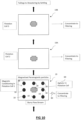
- FIG. 3 With reference to Figures 3 , 7 and 9 , there is illustrated diagrammatically possible usage scenarios for one or more embodiments previously described.
- a flowstream 14 containing particles of valuable ore passes into a magnetic conditioning stage in this instance in the form of processing chamber 18 having at least one magnetic source 10 located therein.
- the source 10 has a high strength magnetic field 23 which can fall away sharply with distance from the source as illustrated in the inset graph of figure 7 .
- a thin walled housing 11 having an external face 11 only a relatively short distance from the magnetic source 10 is utilised so as to maximise the high strength field to which the flowstream 14 is exposed as it passes through the chamber 18.
- the magnetic source 10 is fitted with a scraper 12 (refer Figures 5 , 6 ) or similar arrangement thereby to periodically dislodge material which may have accumulated on face 11.
- the flowstream 14 and a substantial portion of the valuable ore particles entrained within it including any dislodged material 15 continues on to a further treatment tank 19 where valuable ore may be separated from the flowstream 14 by a flotation process wherein aggregated weakly magnetic particles 20 are actively floated in the froth 21.
- the amount of target particles is maximised and the amount of non-target particles entrained in the froth may be minimised.
- those aggregated weakly magnetic particles not selected by the flotation process in tank 19 nor entrained in the froth can pass to a further treatment tank or tanks 19A, 19B (refer to figure 9 ) where a further flotation process may be instigated and wherein a different target particle may be selected for flotation, or the aggregated weakly magnetic particles may pass to a settling tank 22 for dewatering and to tailings 38.
- the magnetic conditioning stage should be placed so as to operate on the flowstream 14 before significant processing occurs in the flotation process in order to optimize the effect of the magnetic conditioning stage 40.
- placing the magnetic conditioning stage very early in the flotation recovery stage supports a method of increasing recovery of the metal portion from the predetermined quantity of ore; said method comprising applying a magnetic field to the ground ore portion in a magnetic conditioning stage while it is contained in the recovered process water subsequent to the grinding stage and prior to the flotation recovery stage.
- FIG. 10 there is illustrated a specific arrangement of processing chamber 19 having at least one magnetic source 18 placed in the circuit between the grinding stage and prior to the flotation recovery stage.
- eight such magnetic sources 18 are placed within a first flotation cell 19 and distributed evenly throughout.
- the first flotation cell 19 contains an agitator 60 which assists in circulating the slurry within the first flotation cell 19.
- Any concentrate 30 is passed to the filter stage 35 the balance, in this instance, is sent to a further flotation cell 19A and from there, in this instance, to yet a further flotation cell 19B.
- filtrate 30 from the flotation recovery process 31 effected within the flotation recovery stage 31 or at least a portion thereof may be recirculated via return line 32 to the grinding stage 33.
- the tailings dewatering stream 36 from the flotation recovery process 31 or at least a portion thereof also passes to return line 32 as part of the process water recirculation system.
- Dewatered, settled solids 37 from the dewatering process 37 exit to a tailings dam 38 or like repository.
- the apparatus illustrated and described may be located in the magnetic conditioning stage 40 illustrated in the process diagram of Figure 3 .
- the apparatus causes the magnetic source 10 to apply an increased range of magnetic field strength to the ground ore portion during this stage thereby to cause increased recovery by improved recovery at the flotation stage 31 arising from the increased range of magnetic field strength; the process interacting with the recovered process water in which the ground ore portion is contained.
- the magnetic field strength applied is at least 4500 Gauss. More preferably the magnetic field strength is at the range of 4500 to 10000 Gauss. More preferably, the magnetic field strength is in the range of 5000 to 10000 Gauss.
- the present invention provides an apparatus 110 for inducing magnetism in a flow stream 112 of an at least partially magnetisable particulate feed material 114 suspended in a liquid.
- the feed material typically includes a mixture of paramagnetic and ferromagnetic particulates present with other nonmagnetic or diamagnetic gangue minerals in a water slurry.
- Paramagnetic particulates usually require a high gradient magnetic field in order to become magnetised.
- Some sulfide minerals containing copper (such as chalcopyrite), zinc (such as sphalerite contaminated with iron) or other transition metals are paramagnetic.
- Ferromagnetic particulates include iron oxide minerals (such as magnetite) and metallic iron particles (from worn grinding media, for example).
- the apparatus 110 includes a treatment chamber in the form of an annularly shaped vessel 116 with an uppermost inlet 118 and a lowermost outlet 120 through which a flow stream of the aforementioned mineral mixture can flow respectively into and out of the vessel 116 with some residence time therein.
- the apparatus can also be used in 'batch' mode, and does not require a continuous flow stream of the mineral slurry mixture.
- either the uppermost inlet 118 or the lowermost outlet 120 can be an inlet or outlet - which is to say flow can be reversed in the apparatus 110.
- the chamber vessel incorporates a central elongate recess 122.
- a magnetic source is able to be selectively activated to induces magnetism in at least some of the particulate feed material 114 located in the vessel 116 by movement of the magnetic source into and out of proximity with the vessel 116.
- the magnetic source is at least one permanent magnet mounted on a motive means in the form of a piston which is connected to a drive so that the piston can be reciprocatingly moved into and out of the recess 122.
- the piston 124 is cylindrically shaped, having a diameter of approximately 300 millimetres and is fitted with a number of inset permanent magnets 126 that are square in shape and have a side dimension of 50 millimetres, made of neodymium or other materials.
- the diameter of the recess 122 in the vessel 116 is 800 millimetres.
- the permanent magnets can be of any shape, size or material and the piston need not be cylindrical, but can be square or triangular in crossection for example, and of any overall length.
- the means by which the piston is moved reciprocatingly with respect to the vessel can include any type of drive including a cam, a spring, an air cylinder (128, as illustrated) or an occentrically rotatable shaft etc.
- the relative movement of the vessel and the magnetic source need not involve a piston being received into a recess in a vessel.
- the magnetic source need only be brought into proximity to the vessel, for example by being moved close to one side of a vessel so that a magnetic field can magnetise the particulate materials located in the vessel.
- the vessel itself may be able to be moved in relation to a stationary magnet.
- the vessel can be of any particular shape, size and orientation to facilitate the magnetic source coming into proximity to the vessel contents.
- the apparatus 110 described allows the introduction of a high gradient magnetic. field to effectively magnetise both the weakly and strongly magnetic particulates 114 for subsequent removal of all particulates by enhanced gravity settling or separation of the weakly magnetic particulates by techniques such as flotation.
- both the weakly and strongly magnetic particulates 114 are attracted and migrate toward the portion of the interior face of the vessel 116 which adjoins the internal elongate recess 122. The particles then become, at least in part, magnetised.
- the dissipation of solids can reduce the possibility of any flow restrictions developing in the vessel and improve the efficiency of the magnet/s.
- a magnetic source can be selectively activated to induces magnetism in at least some of the particulate feed material located in the vessel by use of electromagnet/s located proximal to the vessel.
- the supply current fed to the electromagnet/s can be switched on and off repeatedly to provide the same effect as if a permanent magnet was moved in and out of proximity with the vessel.
- the field of a permanent magnet can be shunted or blocked by moving a magnetic field barrier in between the permanent magnet and the vessel containing the magnetisable particulates.
- the cycle or frequency of movement of the magnetic source may be initiated by a timing device or by sensors that detect the mass of accumulated particles 130.
- the measurement of this mass may be made by determining the interference to the magnetic field or by measuring the resistance to flow of the particulate slurry as the mass of particles 130 increases.
- the inventors have surprisingly discovered that the induced magnetism can cause at least some of the magnetised paramagnetic particles to become aggregated in the liquid flow stream.
- the inventors have observed that the aggregated paramagnetic particles remain aggregated for at least several hours and that the aggregated particles can survive further treatment steps in a mineral separation process such as pumping and agitation.
- the preferred apparatus is able to be operated in a manner to facilitate the subsequent separation of the magnetised paramagnetic feed material fraction from the magnetised ferromagnetic feed material fraction.
- the magnetised paramagnetic feed fraction is also separable from the non-magnetic or diamagnetic gangue minerals.
- sulfide mineral collector reagents such as xanthates or dithiophosphates can ensure that the surfaces of the paramagnetic mineral particles become hydrophobic and more readily attach to the surface of the rising air bubbles in the flotation cell.
- ferromagnetic particles in a particulate mixture of paramagnetic and ferromagnetic minerals are rejected in a flotation process (having no affinity for xanthate or dithiophosphate collectors) and report to gangue or tailings.
- the sulfide mineral collector reagents used were present in the magnetisation treatment vessel 16 prior to any subsequent flotation step.
- the flotation apparatus used can comprise any standard type of agitated flotation cell, flotation column or flotation circuit.
- the present apparatus can allow the introduction of a very high gradient magnetic field to effectively magnetise the both weakly and strongly magnetic particulates.
- the magnetic source When the magnetic source is activated both the weakly and strongly magnetic particulates are attracted toward that magnetic source and become, at least in part, magnetised.
- Previous apparatus and methods have not allowed the use of very high gradient magnetic fields because of the problem of deposition of magnetised feed material around the magnetic source and the low degree of magnetisation of the weakly magnetic particulates.
- the vessel and piston can be made of any suitable materials of construction which wear appropriately and that can be shaped, formed and fitted in the manners so described, such as a metal, metal alloy, hard plastics or ceramic.
- Embodiments of the present invention are applicable in ore processing plants with a view to improving the proportion of fines recovery.
Landscapes
- Manufacture And Refinement Of Metals (AREA)
- Disintegrating Or Milling (AREA)
Claims (14)
- - Verfahren zum Erhöhen der Gewinnung eines Metallanteils aus einer vorbestimmten Menge an Erz in einem Flotationsgewinnungskreislauf, der eine Zerkleinerungsstufe (33), eine Flotationsgewinnungsstufe (31), eine Entwässerungsstufe (37) und eine Filterstufe (35) umfasst, und das die folgenden Schritte bewirkt:- Zerkleinern einer vorbestimmten Menge an Erz in der Zerkleinerungsstufe (33) auf eine vorbestimmte Größe, während das Erz mit Wasser, einschließlich gewonnenem Prozesswasser, berieselt wird, um dadurch einen zerkleinerten Erzanteil zu bilden;- Befördern des zerkleinerten Erzanteils gemischt mit dem gewonnenen Prozesswasser zu der Flotationsgewinnungsstufe (31);
wobei das gewonnene Prozesswasser, das nach der Flotationsgewinnungsstufe (31) aus der Entwässerungsstufe (37) oder der Filterstufe (35) gewonnen wird;- Anwenden von Flotationsgewinnung über die Flotationsstufe auf den zerkleinerten Erzanteil, um dadurch einen gewonnenen Metallanteil aus einem Gemisch des gewonnenen Prozesswassers und des zerkleinerten Erzanteils zu extrahieren;- Zurückleiten zumindest eines Teils des gewonnenen Prozesswassers zu der Zerkleinerungsstufe (33);das Verfahren umfassend ein Anwenden eines Magnetfelds auf den zerkleinerten Erzanteil in einer magnetischen Konditionierungsstufe (40), während er in dem gewonnenen Prozesswasser nach der Zerkleinerungsstufe (33) und vor der Flotationsgewinnungsstufe (31) enthalten ist, um eine Gewinnung der gewünschten paramagnetischen Mineralien durch Aggregation der paramagnetischen Mineralien zu verbessern;
und wobei die Magnetfeldstärke, die in der magnetischen Konditionierungsstufe (40) auf den zerkleinerten Erzanteil angewendet wird, mindestens 4500 Gauß ist. - - Verfahren nach Anspruch 1, wobei die Magnetfeldstärke, die in der magnetischen Konditionierungsstufe (40) auf den zerkleinerten Erzanteil angewendet wird, in dem Bereich von 4500 Gauß bis 10.000 Gauß ist.
- - Verfahren nach Anspruch 1, wobei die Magnetfeldstärke, die in der magnetischen Konditionierungsstufe (40) auf den zerkleinerten Erzanteil angewendet wird, in dem Bereich von 5000 Gauß bis 10.000 Gauß ist.
- - Verfahren nach Anspruch 1, wobei die Magnetfeldstärke, die in der magnetischen Konditionierungsstufe (40) auf den zerkleinerten Erzanteil angewendet wird, in dem Bereich von 6000 Gauß bis 12.000 Gauß ist.
- - Verfahren nach Anspruch 1, wobei zumindest ein Teil des gewonnenen Prozesswassers als Ausgang aus einem Wasser-Mineral-Trennverfahren im Anschluss an die Flotationsstufe in die Zerkleinerungsstufe (33) zurückgeleitet wird.
- - Verfahren nach Anspruch 5, wobei das Wasser-Mineral-Trennverfahren Filtration und/oder Eindicken umfasst.
- - Verfahren nach einem der Ansprüche 1 bis 6, wobei der Wasser-Mineral-Trennverfahren stromabwärts von der Flotationsgewinnungsstufe (31) und der magnetischen Konditionierungsstufe (40) angeordnet ist.
- - System zum Erhöhen der Gewinnung eines Metallanteils aus einer vorbestimmten Menge an Erz in einem Flotationsgewinnungskreislauf, der eine Zerkleinerungsstufe (33), eine Flotationsgewinnungsstufe (31) umfasst, und das die folgenden Schritte bewirkt:- Zerkleinern einer vorbestimmten Menge an Erz auf eine vorbestimmte Größe in der Zerkleinerungsstufe (33), während das Erz mit Wasser, einschließlich gewonnenem Prozesswasser, berieselt wird, um dadurch einen zerkleinerten Erzanteil zu bilden;- Befördern des zerkleinerten Erzanteils gemischt mit dem gewonnenen Prozesswasser zu der Flotationsgewinnungsstufe (31);- Anwenden von Flotationsgewinnung auf den zerkleinerten Erzanteil, um dadurch einen gewonnenen Metallanteil aus einem Gemisch des gewonnenen Prozesswassers und des zerkleinerten Erzanteils zu extrahieren;- Zurückleiten zumindest eines Teils des gewonnenen Prozesswassers zu der Zerkleinerungsstufe (33);wobei das System in einer magnetischen Konditionierungsstufe (40) ein Magnetfeld auf den zerkleinerten Erzanteil anwendet, während er in dem gewonnenen Prozesswasser nach der Zerkleinerungsstufe (33) und vor der Flotationsgewinnungsstufe (31) enthalten ist;
und wobei die Magnetfeldstärke, die in der magnetischen Konditionierungsstufe (40) auf den zerkleinerten Erzanteil angewendet wird, mindestens 4500 Gauß ist; wobei das System eine Gewinnung der gewünschten paramagnetischen Mineralien durch Aggregation der paramagnetischen Mineralien verbessert, um dadurch eine Gewinnung aus den stromabwärtigen Wasser-Mineral-Trennverfahren zu verbessern. - - System nach Anspruch 8, wobei die Magnetfeldstärke, die in der magnetischen Konditionierungsstufe (40) auf den zerkleinerten Erzanteil angewendet wird, in dem Bereich von 4500 Gauß bis 10.000 Gauß ist.
- - System nach Anspruch 8, wobei die Magnetfeldstärke, die in der magnetischen Konditionierungsstufe (40) auf den zerkleinerten Erzanteil angewendet wird, in dem Bereich von 5000 Gauß bis 10.000 Gauß ist.
- - System nach Anspruch 8, wobei die Magnetfeldstärke, die in der magnetischen Konditionierungsstufe (40) auf den zerkleinerten Erzanteil angewendet wird, in dem Bereich von 6000 Gauß bis 12.000 Gauß ist.
- - Systemnach Anspruch 8, wobei der zumindest eine Teil des gewonnenen Prozesswassers als Ausgang aus einem Wasser-Mineral-Trennverfahren in die Zerkleinerungsstufe (33) zurückgeleitet wird.
- - System nach Anspruch 12, wobei das Wasser-Mineral-Trennverfahren Filtration und/oder Eindicken umfasst.
- - System nach einem der Ansprüche 8 bis 13, wobei sich das Wasser-Mineral-Trennverfahren stromabwärts von der Flotationsgewinnungsstufe (31) und der magnetischen Konditionierungsstufe (40) befindet.
Applications Claiming Priority (3)
| Application Number | Priority Date | Filing Date | Title |
|---|---|---|---|
| AU2018902763A AU2018902763A0 (en) | 2018-07-30 | Apparatus and Process for Improved Ore Recovery | |
| AU2018904830A AU2018904830A0 (en) | 2018-12-19 | Apparatus and Process for Improved Ore Recovery | |
| PCT/AU2019/050800 WO2020024008A1 (en) | 2018-07-30 | 2019-07-30 | Apparatus and process for improved ore recovery |
Publications (4)
| Publication Number | Publication Date |
|---|---|
| EP3829772A1 EP3829772A1 (de) | 2021-06-09 |
| EP3829772A4 EP3829772A4 (de) | 2022-04-27 |
| EP3829772C0 EP3829772C0 (de) | 2025-03-05 |
| EP3829772B1 true EP3829772B1 (de) | 2025-03-05 |
Family
ID=69230437
Family Applications (1)
| Application Number | Title | Priority Date | Filing Date |
|---|---|---|---|
| EP19843887.1A Active EP3829772B1 (de) | 2018-07-30 | 2019-07-30 | Vorrichtung und verfahren zur verbesserten erzrückgewinnung |
Country Status (10)
| Country | Link |
|---|---|
| US (1) | US12162023B2 (de) |
| EP (1) | EP3829772B1 (de) |
| AU (2) | AU2019314765B2 (de) |
| CA (1) | CA3107648A1 (de) |
| CL (1) | CL2021000248A1 (de) |
| ES (1) | ES3028732T3 (de) |
| PE (1) | PE20210391A1 (de) |
| PL (1) | PL3829772T3 (de) |
| WO (1) | WO2020024008A1 (de) |
| ZA (1) | ZA202100953B (de) |
Families Citing this family (3)
| Publication number | Priority date | Publication date | Assignee | Title |
|---|---|---|---|---|
| CA3157827A1 (en) * | 2019-10-28 | 2021-05-06 | Metso Outotec Finland Oy | Method for process water treatment |
| CN117718319B (zh) * | 2023-12-14 | 2025-08-22 | 上海秦望科技有限公司 | 一种环保型炉渣处理控制方法及装置 |
| CN118950252A (zh) * | 2024-10-12 | 2024-11-15 | 山东盛泰矿业科技有限公司 | 一种矿物开采用洗矿设备 |
Family Cites Families (10)
| Publication number | Priority date | Publication date | Assignee | Title |
|---|---|---|---|---|
| EP0313116B1 (de) * | 1987-10-22 | 1993-08-04 | Metallgesellschaft Ag | Verfahren zur Aufbereitung von kontaminierten Böden |
| PL215156B1 (pl) * | 2001-02-16 | 2013-10-31 | Ausmetec Pty Ltd | Urzadzenie i sposób indukowania magnetyzmu |
| PH12012502147A1 (en) * | 2010-04-29 | 2019-06-26 | Ausmetec Pty Ltd | Apparatus for continual magnetisation of a slurry |
| EP3094412A1 (de) * | 2014-01-14 | 2016-11-23 | Imerys Ceramics France | Konditionierungsverfahren |
| CN104722393B (zh) * | 2015-03-19 | 2017-11-17 | 长沙矿冶研究院有限责任公司 | 一种提高微细粒镜铁矿回收率的选矿方法 |
| PL245083B1 (pl) * | 2015-04-22 | 2024-05-06 | Anglo American Services Uk Ltd | Sposób pozyskiwania metali wartościowych z rudy |
| WO2017049259A1 (en) * | 2015-09-18 | 2017-03-23 | Thomas Valerio | System and method for recovering metals from electronic scrap and auto shred residue fines |
| CN105214837B (zh) | 2015-10-14 | 2017-06-20 | 广州有色金属研究院 | 一种富含磁黄铁矿和黄铁矿的铜硫矿选矿方法 |
| JP6116733B1 (ja) * | 2016-04-25 | 2017-04-19 | 智治 竹内 | 重金属分離システム |
| WO2020128137A1 (en) * | 2018-12-18 | 2020-06-25 | Outotec (Finland) Oy | Method and arrangement for process water treatment |
-
2019
- 2019-07-30 AU AU2019314765A patent/AU2019314765B2/en not_active Expired - Fee Related
- 2019-07-30 EP EP19843887.1A patent/EP3829772B1/de active Active
- 2019-07-30 PL PL19843887.1T patent/PL3829772T3/pl unknown
- 2019-07-30 CA CA3107648A patent/CA3107648A1/en active Pending
- 2019-07-30 ES ES19843887T patent/ES3028732T3/es active Active
- 2019-07-30 PE PE2021000131A patent/PE20210391A1/es unknown
- 2019-07-30 WO PCT/AU2019/050800 patent/WO2020024008A1/en not_active Ceased
- 2019-07-30 US US17/263,998 patent/US12162023B2/en active Active
-
2021
- 2021-01-29 CL CL2021000248A patent/CL2021000248A1/es unknown
- 2021-02-11 ZA ZA2021/00953A patent/ZA202100953B/en unknown
-
2024
- 2024-09-06 AU AU2024219464A patent/AU2024219464B2/en active Active
Also Published As
| Publication number | Publication date |
|---|---|
| AU2024219464A1 (en) | 2024-09-26 |
| ES3028732T3 (en) | 2025-06-20 |
| EP3829772C0 (de) | 2025-03-05 |
| EP3829772A4 (de) | 2022-04-27 |
| CL2021000248A1 (es) | 2021-06-25 |
| ZA202100953B (en) | 2022-09-28 |
| PL3829772T3 (pl) | 2025-07-21 |
| WO2020024008A1 (en) | 2020-02-06 |
| EP3829772A1 (de) | 2021-06-09 |
| AU2019314765A1 (en) | 2021-03-11 |
| CA3107648A1 (en) | 2020-02-06 |
| US20210316314A1 (en) | 2021-10-14 |
| PE20210391A1 (es) | 2021-03-02 |
| AU2019314765B2 (en) | 2024-06-13 |
| AU2024219464B2 (en) | 2024-10-24 |
| US12162023B2 (en) | 2024-12-10 |
Similar Documents
| Publication | Publication Date | Title |
|---|---|---|
| AU2024219464B2 (en) | Apparatus and Process for Improved Ore Recovery | |
| AU2011245073B2 (en) | Apparatus for continual magnetisation of a slurry | |
| Parker | The physics of magnetic separation | |
| CN117295557A (zh) | 矿物分离方法 | |
| CN1994578A (zh) | 一种高梯度磁选机 | |
| EP1368127B1 (de) | Vorrichtung und verfahren zur induzierung von magnetismus | |
| CN213255062U (zh) | 一种钒钛磁铁矿总尾矿的预分选装置 | |
| CA1214435A (en) | Ore beneficiation | |
| CN116328938B (zh) | 一种回收磁铁矿的弱场强高梯度磁选机及其配置、选矿工艺 | |
| EA047360B1 (ru) | Устройство и способ для улучшенного извлечения руды | |
| WO2013163678A1 (en) | Recovering mineral from ore | |
| Da-He | Research and commercialisation of treatment of fine Ilmenite with SLON magnetic separators | |
| CN212189568U (zh) | 一种高效环保型石英砂提纯装置 | |
| CN110947516A (zh) | 一种铁精矿降锌方法 | |
| CN218609838U (zh) | 一种适用于微细粒磁赤铁矿的磁选机组装置 | |
| Khalafalla et al. | Beneficiation with Magnetic fluids | |
| Zheng et al. | Investigation of binary salt fluids with higher volume susceptibility for high gradient magnetic separation coupling with magnetic fluid | |
| AU2002233040B2 (en) | An apparatus and process for inducing magnetism | |
| Güngör | Production of heavy-media-quality magnetite concentrate from Kesikköprü iron ore tailings | |
| CN119327608A (zh) | 一种低品位细粒径钒钛磁铁尾矿预富集方法 | |
| CN120940065A (zh) | 一种微细粒难选赤铁矿石的粗细分级分选方法 | |
| CN113145302A (zh) | 一种磁铁矿尾矿含水提纯铁精粉的方法 | |
| CN113145303A (zh) | 一种磁铁矿尾矿含水提纯铁精粉的成套设备 | |
| Sema et al. | Increasing the flotation recovery of< 10 µm PGE with magnetic conditioning–A plant evaluation | |
| ĆALIĆ et al. | LIMONITE CONCENTRATION FROM MUD |
Legal Events
| Date | Code | Title | Description |
|---|---|---|---|
| STAA | Information on the status of an ep patent application or granted ep patent |
Free format text: STATUS: THE INTERNATIONAL PUBLICATION HAS BEEN MADE |
|
| PUAI | Public reference made under article 153(3) epc to a published international application that has entered the european phase |
Free format text: ORIGINAL CODE: 0009012 |
|
| STAA | Information on the status of an ep patent application or granted ep patent |
Free format text: STATUS: REQUEST FOR EXAMINATION WAS MADE |
|
| 17P | Request for examination filed |
Effective date: 20210226 |
|
| AK | Designated contracting states |
Kind code of ref document: A1 Designated state(s): AL AT BE BG CH CY CZ DE DK EE ES FI FR GB GR HR HU IE IS IT LI LT LU LV MC MK MT NL NO PL PT RO RS SE SI SK SM TR |
|
| DAV | Request for validation of the european patent (deleted) | ||
| DAX | Request for extension of the european patent (deleted) | ||
| A4 | Supplementary search report drawn up and despatched |
Effective date: 20220330 |
|
| RIC1 | Information provided on ipc code assigned before grant |
Ipc: B03C 1/033 20060101ALI20220324BHEP Ipc: B03D 1/02 20060101ALI20220324BHEP Ipc: B03C 1/28 20060101ALI20220324BHEP Ipc: B03D 1/00 20060101ALI20220324BHEP Ipc: B03C 1/30 20060101ALI20220324BHEP Ipc: B03C 1/025 20060101ALI20220324BHEP Ipc: B03C 1/02 20060101AFI20220324BHEP |
|
| STAA | Information on the status of an ep patent application or granted ep patent |
Free format text: STATUS: EXAMINATION IS IN PROGRESS |
|
| 17Q | First examination report despatched |
Effective date: 20240325 |
|
| GRAP | Despatch of communication of intention to grant a patent |
Free format text: ORIGINAL CODE: EPIDOSNIGR1 |
|
| STAA | Information on the status of an ep patent application or granted ep patent |
Free format text: STATUS: GRANT OF PATENT IS INTENDED |
|
| INTG | Intention to grant announced |
Effective date: 20240924 |
|
| GRAS | Grant fee paid |
Free format text: ORIGINAL CODE: EPIDOSNIGR3 |
|
| GRAA | (expected) grant |
Free format text: ORIGINAL CODE: 0009210 |
|
| STAA | Information on the status of an ep patent application or granted ep patent |
Free format text: STATUS: THE PATENT HAS BEEN GRANTED |
|
| AK | Designated contracting states |
Kind code of ref document: B1 Designated state(s): AL AT BE BG CH CY CZ DE DK EE ES FI FR GB GR HR HU IE IS IT LI LT LU LV MC MK MT NL NO PL PT RO RS SE SI SK SM TR |
|
| REG | Reference to a national code |
Ref country code: GB Ref legal event code: FG4D |
|
| REG | Reference to a national code |
Ref country code: CH Ref legal event code: EP |
|
| REG | Reference to a national code |
Ref country code: DE Ref legal event code: R096 Ref document number: 602019066994 Country of ref document: DE |
|
| REG | Reference to a national code |
Ref country code: IE Ref legal event code: FG4D |
|
| U01 | Request for unitary effect filed |
Effective date: 20250403 |
|
| U07 | Unitary effect registered |
Designated state(s): AT BE BG DE DK EE FI FR IT LT LU LV MT NL PT RO SE SI Effective date: 20250410 |
|
| REG | Reference to a national code |
Ref country code: ES Ref legal event code: FG2A Ref document number: 3028732 Country of ref document: ES Kind code of ref document: T3 Effective date: 20250620 |
|
| PG25 | Lapsed in a contracting state [announced via postgrant information from national office to epo] |
Ref country code: RS Free format text: LAPSE BECAUSE OF FAILURE TO SUBMIT A TRANSLATION OF THE DESCRIPTION OR TO PAY THE FEE WITHIN THE PRESCRIBED TIME-LIMIT Effective date: 20250605 |
|
| PG25 | Lapsed in a contracting state [announced via postgrant information from national office to epo] |
Ref country code: NO Free format text: LAPSE BECAUSE OF FAILURE TO SUBMIT A TRANSLATION OF THE DESCRIPTION OR TO PAY THE FEE WITHIN THE PRESCRIBED TIME-LIMIT Effective date: 20250605 |
|
| PG25 | Lapsed in a contracting state [announced via postgrant information from national office to epo] |
Ref country code: HR Free format text: LAPSE BECAUSE OF FAILURE TO SUBMIT A TRANSLATION OF THE DESCRIPTION OR TO PAY THE FEE WITHIN THE PRESCRIBED TIME-LIMIT Effective date: 20250305 |
|
| PG25 | Lapsed in a contracting state [announced via postgrant information from national office to epo] |
Ref country code: GR Free format text: LAPSE BECAUSE OF FAILURE TO SUBMIT A TRANSLATION OF THE DESCRIPTION OR TO PAY THE FEE WITHIN THE PRESCRIBED TIME-LIMIT Effective date: 20250606 |
|
| U20 | Renewal fee for the european patent with unitary effect paid |
Year of fee payment: 7 Effective date: 20250730 |
|
| PG25 | Lapsed in a contracting state [announced via postgrant information from national office to epo] |
Ref country code: SM Free format text: LAPSE BECAUSE OF FAILURE TO SUBMIT A TRANSLATION OF THE DESCRIPTION OR TO PAY THE FEE WITHIN THE PRESCRIBED TIME-LIMIT Effective date: 20250305 |
|
| PGFP | Annual fee paid to national office [announced via postgrant information from national office to epo] |
Ref country code: ES Payment date: 20250801 Year of fee payment: 7 |
|
| PGFP | Annual fee paid to national office [announced via postgrant information from national office to epo] |
Ref country code: PL Payment date: 20250724 Year of fee payment: 7 Ref country code: TR Payment date: 20250729 Year of fee payment: 7 |
|
| PG25 | Lapsed in a contracting state [announced via postgrant information from national office to epo] |
Ref country code: CZ Free format text: LAPSE BECAUSE OF FAILURE TO SUBMIT A TRANSLATION OF THE DESCRIPTION OR TO PAY THE FEE WITHIN THE PRESCRIBED TIME-LIMIT Effective date: 20250305 |
|
| PG25 | Lapsed in a contracting state [announced via postgrant information from national office to epo] |
Ref country code: SK Free format text: LAPSE BECAUSE OF FAILURE TO SUBMIT A TRANSLATION OF THE DESCRIPTION OR TO PAY THE FEE WITHIN THE PRESCRIBED TIME-LIMIT Effective date: 20250305 |
|
| PG25 | Lapsed in a contracting state [announced via postgrant information from national office to epo] |
Ref country code: IS Free format text: LAPSE BECAUSE OF FAILURE TO SUBMIT A TRANSLATION OF THE DESCRIPTION OR TO PAY THE FEE WITHIN THE PRESCRIBED TIME-LIMIT Effective date: 20250705 |
|
| PLBE | No opposition filed within time limit |
Free format text: ORIGINAL CODE: 0009261 |
|
| STAA | Information on the status of an ep patent application or granted ep patent |
Free format text: STATUS: NO OPPOSITION FILED WITHIN TIME LIMIT |
|
| REG | Reference to a national code |
Ref country code: CH Ref legal event code: L10 Free format text: ST27 STATUS EVENT CODE: U-0-0-L10-L00 (AS PROVIDED BY THE NATIONAL OFFICE) Effective date: 20260114 |
|
| 26N | No opposition filed |
Effective date: 20251208 |
|
| REG | Reference to a national code |
Ref country code: CH Ref legal event code: H13 Free format text: ST27 STATUS EVENT CODE: U-0-0-H10-H13 (AS PROVIDED BY THE NATIONAL OFFICE) Effective date: 20260224 |
|
| GBPC | Gb: european patent ceased through non-payment of renewal fee |
Effective date: 20250730 |
|
| PG25 | Lapsed in a contracting state [announced via postgrant information from national office to epo] |
Ref country code: GB Free format text: LAPSE BECAUSE OF NON-PAYMENT OF DUE FEES Effective date: 20250730 |
|
| PG25 | Lapsed in a contracting state [announced via postgrant information from national office to epo] |
Ref country code: CH Free format text: LAPSE BECAUSE OF NON-PAYMENT OF DUE FEES Effective date: 20250731 |