EP3828874A1 - Poche en matériau souple a affichage lumineux - Google Patents
Poche en matériau souple a affichage lumineux Download PDFInfo
- Publication number
- EP3828874A1 EP3828874A1 EP20210350.3A EP20210350A EP3828874A1 EP 3828874 A1 EP3828874 A1 EP 3828874A1 EP 20210350 A EP20210350 A EP 20210350A EP 3828874 A1 EP3828874 A1 EP 3828874A1
- Authority
- EP
- European Patent Office
- Prior art keywords
- light
- flexible material
- emitting diodes
- electronic card
- Prior art date
- Legal status (The legal status is an assumption and is not a legal conclusion. Google has not performed a legal analysis and makes no representation as to the accuracy of the status listed.)
- Granted
Links
Images



Classifications
-
- G—PHYSICS
- G09—EDUCATION; CRYPTOGRAPHY; DISPLAY; ADVERTISING; SEALS
- G09F—DISPLAYING; ADVERTISING; SIGNS; LABELS OR NAME-PLATES; SEALS
- G09F13/00—Illuminated signs; Luminous advertising
- G09F13/04—Signs, boards or panels, illuminated from behind the insignia
-
- G—PHYSICS
- G09—EDUCATION; CRYPTOGRAPHY; DISPLAY; ADVERTISING; SEALS
- G09F—DISPLAYING; ADVERTISING; SIGNS; LABELS OR NAME-PLATES; SEALS
- G09F9/00—Indicating arrangements for variable information in which the information is built-up on a support by selection or combination of individual elements
- G09F9/30—Indicating arrangements for variable information in which the information is built-up on a support by selection or combination of individual elements in which the desired character or characters are formed by combining individual elements
- G09F9/33—Indicating arrangements for variable information in which the information is built-up on a support by selection or combination of individual elements in which the desired character or characters are formed by combining individual elements being semiconductor devices, e.g. diodes
-
- G—PHYSICS
- G09—EDUCATION; CRYPTOGRAPHY; DISPLAY; ADVERTISING; SEALS
- G09F—DISPLAYING; ADVERTISING; SIGNS; LABELS OR NAME-PLATES; SEALS
- G09F13/00—Illuminated signs; Luminous advertising
- G09F13/005—Illumination controller or illuminated signs including an illumination control system
-
- G—PHYSICS
- G09—EDUCATION; CRYPTOGRAPHY; DISPLAY; ADVERTISING; SEALS
- G09F—DISPLAYING; ADVERTISING; SIGNS; LABELS OR NAME-PLATES; SEALS
- G09F13/00—Illuminated signs; Luminous advertising
- G09F13/04—Signs, boards or panels, illuminated from behind the insignia
- G09F13/0418—Constructional details
- G09F13/0468—Signs, boards or panels with tensioned or flexible display surface
-
- G—PHYSICS
- G09—EDUCATION; CRYPTOGRAPHY; DISPLAY; ADVERTISING; SEALS
- G09F—DISPLAYING; ADVERTISING; SIGNS; LABELS OR NAME-PLATES; SEALS
- G09F17/00—Flags; Banners; Mountings therefor
-
- G—PHYSICS
- G09—EDUCATION; CRYPTOGRAPHY; DISPLAY; ADVERTISING; SEALS
- G09F—DISPLAYING; ADVERTISING; SIGNS; LABELS OR NAME-PLATES; SEALS
- G09F23/00—Advertising on or in specific articles, e.g. ashtrays, letter-boxes
- G09F23/06—Advertising on or in specific articles, e.g. ashtrays, letter-boxes the advertising matter being combined with articles for restaurants, shops or offices
-
- G—PHYSICS
- G09—EDUCATION; CRYPTOGRAPHY; DISPLAY; ADVERTISING; SEALS
- G09F—DISPLAYING; ADVERTISING; SIGNS; LABELS OR NAME-PLATES; SEALS
- G09F9/00—Indicating arrangements for variable information in which the information is built-up on a support by selection or combination of individual elements
- G09F9/30—Indicating arrangements for variable information in which the information is built-up on a support by selection or combination of individual elements in which the desired character or characters are formed by combining individual elements
- G09F9/301—Indicating arrangements for variable information in which the information is built-up on a support by selection or combination of individual elements in which the desired character or characters are formed by combining individual elements flexible foldable or roll-able electronic displays, e.g. thin LCD, OLED
-
- E—FIXED CONSTRUCTIONS
- E04—BUILDING
- E04F—FINISHING WORK ON BUILDINGS, e.g. STAIRS, FLOORS
- E04F10/00—Sunshades, e.g. Florentine blinds or jalousies; Outside screens; Awnings or baldachins
- E04F10/02—Sunshades, e.g. Florentine blinds or jalousies; Outside screens; Awnings or baldachins of flexible canopy materials, e.g. canvas ; Baldachins
- E04F10/06—Sunshades, e.g. Florentine blinds or jalousies; Outside screens; Awnings or baldachins of flexible canopy materials, e.g. canvas ; Baldachins comprising a roller-blind with means for holding the end away from a building
- E04F10/0692—Front bars
- E04F10/0696—Front bars with means to attach an auxiliary screen
-
- G—PHYSICS
- G09—EDUCATION; CRYPTOGRAPHY; DISPLAY; ADVERTISING; SEALS
- G09F—DISPLAYING; ADVERTISING; SIGNS; LABELS OR NAME-PLATES; SEALS
- G09F13/00—Illuminated signs; Luminous advertising
- G09F13/04—Signs, boards or panels, illuminated from behind the insignia
- G09F13/08—Signs, boards or panels, illuminated from behind the insignia using both translucent and non-translucent layers
-
- G—PHYSICS
- G09—EDUCATION; CRYPTOGRAPHY; DISPLAY; ADVERTISING; SEALS
- G09F—DISPLAYING; ADVERTISING; SIGNS; LABELS OR NAME-PLATES; SEALS
- G09F13/00—Illuminated signs; Luminous advertising
- G09F13/20—Illuminated signs; Luminous advertising with luminescent surfaces or parts
- G09F13/22—Illuminated signs; Luminous advertising with luminescent surfaces or parts electroluminescent
- G09F2013/222—Illuminated signs; Luminous advertising with luminescent surfaces or parts electroluminescent with LEDs
Definitions
- the invention relates to the field of light display and relates more particularly to a pocket made of flexible material in which is inserted a light display module made from a plurality of light-emitting diodes.
- the invention aims in particular to allow a luminous display of patterns, for example for advertising purposes, in structures comprising walls made of a flexible material such as, for example, signs of the flag or kakemono type, blinds, valances. , umbrellas, patio dividers, tarpaulins, drapes, etc.
- this type of sign comprises, as standard, a structure, for example metallic, on which light tubes are fixed. These signs are generally mounted on walls or on poles.
- this type of device has several drawbacks. First of all, it is not necessary to fix it on a solid element such as a wall or a pole, in particular when its mass is important. Then, it can be degraded by the meteorological elements or by individuals who would have direct access to it. Finally, it can represent a visual nuisance when it is not integrated into the landscape, in particular into the urban landscape.
- patterns can be integrated into existing structures of flexible material such as flags, kakemonos, blinds, parasols, valances, terrace dividers, tarpaulins, hangings, or any object with suitable flexible material.
- the flexible material may for example be fabric such as awning, flag or parasol fabric.
- the pocket can have more than two thicknesses and / or more than two sides.
- the electronic card comprises a microcontroller or a processor configured to implement the instructions for controlling the lighting of the light-emitting diodes, recorded in the memory zone, in order to create a predetermined display pattern.
- the lighting of the light emitting diodes can make it possible to display patterns such as characters, logos, images or videos.
- the at least one predetermined display pattern is displayed statically.
- the at least one predetermined display pattern is displayed dynamically in the form of an animation, for example of flashing or scrolling type, in particular when the at least one pattern consists of several alphanumeric characters which may for example scroll from left to right.
- an animation for example of flashing or scrolling type
- the pocket has a total thickness of less than 3 cm in order in particular to be able to integrate harmoniously into a structure as mentioned above.
- the thickness of the electronic card is less than 2 cm in order to make the pocket relatively flat with a thickness less than 3 cm, the total thickness of the layers of flexible material then being in this case preferably less than 1 cm. .
- the pocket comprises at least one opening on at least one of its faces.
- This or these openings may be of various shapes and sizes, for example rectangular or in the form of an alphanumeric character or of a logo.
- the pocket comprises a transparent or translucent plate, preferably made of plexiglass, mounted on, in or behind said at least one opening.
- a transparent or translucent plate preferably made of plexiglass, mounted on, in or behind said at least one opening.
- a translucent plate makes it possible to hide the electronic card and thus improve the aesthetics of the pocket.
- the flexible material is glued to the plate in order to seal the bag.
- the pocket has no opening on its faces, which makes it easy to manufacture.
- the portion of flexible material located opposite the light-emitting diodes is at least partly translucent or transparent in order to let the light pass to the outside of the pocket and thus make it possible to visualize the light.
- the pocket can thus be perfectly integrated, or even camouflaged, in a structure, in particular when the diodes are off.
- the electronic card comprises a protective varnish, for example of silicone, in order to seal it, preferably against liquids.
- a protective varnish for example of silicone
- the light display module comprises a protective case in which the electronic card is mounted in order to protect said electronic card from the elements. exterior such as, for example, dust, flames, sunlight and / or liquids, thus increasing its lifespan.
- the memory zone of the electronic card is programmable remotely, for example on a wireless communication link of the wifi or Bluetooth® type, in order to modify the display pattern or patterns produced by the light-emitting diodes.
- the remote programming of the electronic card is carried out using a dedicated application, for example installed on a smartphone, which makes it simple and fast.
- the pocket comprises an electrical energy storage battery in order to make the pocket easily transportable and installable.
- a battery can also be mounted in the internal space of the pocket or else be fixed outside said internal space.
- the pocket is capable of being electrically connected to an electrical network in order to be supplied with electricity, such a network being
- the pocket comprises a solar panel making it possible to recharge the battery if necessary and / or to operate the electronic card.
- This panel can advantageously be mounted in the internal space of the pocket, in line with an opening formed in one of the faces of the pocket or else be mounted in a dedicated pocket or even be mounted outside the pocket. pocket by being connected to the battery by an electric cable.
- the pocket can include any type of device such as, for example, an odor diffuser, used for example in bakeries to diffuse pastry smells, or a sound transmitter equipped with a loudspeaker in order to diffuse audio programs (music, announcements, etc.).
- an odor diffuser used for example in bakeries to diffuse pastry smells
- a sound transmitter equipped with a loudspeaker in order to diffuse audio programs (music, announcements, etc.).
- the pocket has on the outside of at least one of its faces complementary impressions of the display pattern (s) produced by the switching on of the light-emitting diodes in order to create a visual interaction between the switching on of the light emitting diodes. light emitting diodes and said pocket face.
- the invention also relates to a structure comprising a pocket as presented above.
- the structure can include or consist of a support, such as for example a frame, a wall, a wall, a mast, a stake, a cable, a rope, on which is mounted the pocket (flag, kakemono) or on which is mounted an element at least partly made of flexible material comprising the pocket (awning, parasol, patio divider, hanging, tarpaulin).
- the invention also relates to a method of manufacturing a pocket of flexible material for light display as presented above, said method comprising a step of inserting the electronic card (or the protective case comprising the electronic card) in the internal space formed between the two layers of flexible material and a step of closing the pocket.
- the manufacture of the pocket according to the invention is thus quick and easy because, the diodes being mounted on the electronic card, the insertion of the electronic card (or of the box) makes it possible to place all the electronics of the device in space. internal in a single gesture.
- the invention also relates to a method of display from a pocket as presented above, said method comprising a step of controlling the light-emitting diodes from the instructions, for example implemented by the microcontroller, in order to switch on and off. / or to switch off the light-emitting diodes according to a predetermined pattern, preferably dynamically to obtain a display making it possible to view an animation, for example by scrolling or flashing.
- the invention also relates to a computer program product characterized in that it comprises a set of program code instructions which, when executed by one or more processors, configure the processor or processors to implement a process. display method as presented above.
- the pocket according to the invention is suitable for being integrated into an existing structure or else to be mounted on a support such as for example a wall or a mast.
- the pocket can be integrated or even constitute a flag or a kakemono or be inserted in a blind fabric, for example a roller, in a blind valance, in a parasol canvas, in a parasol valance, in a terrace divider. , in a tarpaulin, or any suitable flexible material structure.
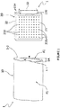
- the pocket 1 comprises two thicknesses 1-1, 1-2 of a flexible material 10, between which is delimited an internal space E, and a light display module 20, housed in said internal space E.
- the pocket 1 thus presents two sides F1, F2.
- the pocket 1 could comprise more than two thicknesses 1-1, 1-2 and / or more than two faces F1, F2.
- the flexible material 10 can for example be made of fabric or any suitable material such as, for example, awning, flag, parasol, tarpaulin, PVC or polyester fabric.
- the pocket 1 has a total thickness 1A (ie when the light display module 20 is housed in the internal space E as illustrated in the figures.
- the thicknesses 1-1, 1-2 can be glued, sewn or fixed together by a strip of hook and loop adhesive.
- the pocket 1 can be integrated into a flexible material of an existing structure by stitching or gluing or fixing by hook-and-loop tape or any other suitable fixing means or else be integral with said flexible material of an existing structure, for example by constituting the two thicknesses of said material, in particular in the case of a flag, a kakemono, an awning fabric, etc.
- the pocket 1 according to the invention could also be integrated into a rigid structure such as a rigid wall, a wall, etc.
- the light display module 20 comprises an electronic card 21 with two faces, for example of rectangular shape, provided with a plurality of light-emitting diodes 210 on one, the other or both faces. More precisely, the electronic card 21 is preferably in the form of a printed circuit and comprises a plurality of electronic components including light-emitting diodes 210 and a memory area 220 in which are recorded instructions making it possible to control the ignition of said diodes. light emitting 210 to create a predetermined display pattern.
- the electronic card 21 comprises a microcontroller or a processor (not shown) configured to implement said instructions for controlling the ignition of said light-emitting diodes 210 in order to create a predetermined display pattern.
- the number of light-emitting diodes 210 present on a face F1, F2 of pocket 1 is greater than or equal to fifty, preferably greater than or equal to one hundred.
- the electronic card 21 has dimensions substantially equal to but slightly smaller than those of the internal space E in order, once inserted into the internal space E, to be held by the flexible material constituting the edges of the. 'internal space E.
- the electronic card could comprise more than one electronic card 21, for example two electronic cards 21 comprising light emitting diodes 210 on one of the their face and placed back to back in the internal space E so as to illuminate the two faces F1, F2 of pocket 1.
- turning on the light emitting diodes 210 can display patterns such as characters, logos, images or videos.
- the patterns can be displayed statically or else dynamically, for example by flashing or scrolling, as illustrated on figure 4 .
- the electronic card 21 comprises a protective varnish.
- the electronic card 21 is housed in a protective case 22, itself placed in the internal space E of the pocket in order to seal the electronic card 21, protecting it in particular from rainwater and water. flames.
- the thickness of the electronic card 21 or, when the electronic card 21 is mounted in a protective case 22 as illustrated in FIG. figure 1 the thickness 22A of the protective case 22 is less than 2 cm in order to make the pocket 1 relatively flat with a total thickness 1A of less than 3 cm.
- the electronic card 21 can be programmed by replacing the memory zone 220 or else by modifying the instructions recorded in the memory zone 220, for example via a communication cable or else via a wireless interface, in particular of the wifi or Bluetooth® type.
- the memory zone 220 can for example be programmed remotely using a dedicated application installed on a smartphone.
- the pocket 1 may include a battery 30 electrically connected to the electronic card 21 in order to supply it electrically.
- This battery 30 can also be mounted in the internal space E of the pocket 1 or else be fixed to the outside of said internal space E. In the example illustrated in FIG. figure 1 , the battery 30 is mounted on one side of the protection box 22. The battery 30 could also be mounted on one side of the electronic card 21.
- the pocket 1 can include a solar panel (not shown) in order to recharge said battery 30 or to directly supply the electronic card 21.
- This panel can be mounted in the internal space E of the pocket 1, to the right of 'an opening formed in one of the faces F1, F2 of the pocket 1 or else be mounted outside the pocket 1 and connected to the battery 30 or to the electronic card 21 by an electric cable.
- the electronic card 21 can be directly connected to a domestic electrical network via an electrical cable (not shown).
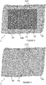
- the pocket 1 comprises an opening 10A formed in the flexible material 10 on one F1 of the faces F1, F2 of the pocket 1 in order to make the electronic card 21 visible from the outside.
- the pocket 1 can comprise one or more openings 10A on one F1 or the other F2 of its two faces F1, F2 or even on its two faces F1, F2.
- This or these openings 10A can have any shape and any dimensions.
- a transparent or translucent plate (not visible on the figure 2 ), preferably carried out in plexiglass (or any suitable material), can be positioned on, in or behind the opening (s) 10A placed opposite the light-emitting diodes 210 of the electronic card 21 in order to protect them and / or reduce the highlights and / or improve the diffusion of light and / or conceal the electronic card 21.
- the portion of flexible material 10 of the pocket 1 which is in line with said plate can be glued to said plate in order to seal the pocket 1.
- the pocket 1 has no opening on its faces F1, F2.
- the faces F1, F2 of the pocket 1 are solid.
- the flexible material 10 of the pocket 1 is at least partly translucent or transparent opposite the light-emitting diodes 210 in order to let the light pass to the outside of the pocket 1 so as to be able to see the display produced by the light-emitting diodes 210 through the thickness of the flexible material 10 of the bag 1.
- the flexible material 10 appears in light gray and the light emitting diodes 210 which are on appear in white on the figures 2 and 3 .
- the electronic card 21 appears in dark gray on the figure 2 in order to distinguish the opening 10A and the electronic card 21 from the flexible material 10.
- the flexible material 10 and the electronic card 21 when it is visible appear in white and the light-emitting diodes 210 on appear indistinctly in white or black on the figures 5 to 12 .
- the pocket 1 may include on the outside of at least one of its faces F1, F2, additional impressions of the display pattern (s). predetermined produced by the lighting of the light emitting diodes 210.
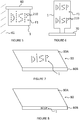
- the light-emitting diodes 210 can provide the animation of a motor vehicle moving from one edge to the other of the electronic card 21 on a road 5 drawn on the outer wall of one F1 of the faces F1, F2 of pocket 1.
- one F1, the other F2 or both faces F1, F2 of pocket 1 could include printed or screen-printed elements that are not complementary to the predetermined display pattern (s).
- FIG 5 a first embodiment of the pocket 1 according to the invention in which the pocket 1 is integrated in the fabric of a flag mounted on a pole 60 fixed to a wall 61 and makes it possible to generate a “DISP” display pattern, which can be static or dynamic (flashing, scrolling, ).
- the mast 60 is horizontal but it could just as well be vertical or oblique.
- FIG. 6 We have represented at the figure 6 a second embodiment of the pocket 1 according to the invention in which at least one pocket 1 is integrated in the canvas of a kakemono mounted on a support 70.
- two chains of alphanumeric characters “DISP” are visible through the visible face F1 of the pocket 1.
- These two alphanumeric character strings can be generated by the same electronic card 21 housed in a single pocket 1 or else by two electronic cards 21 positioned one above the other in the 'internal space E of the same pocket 1 or in two separate pockets 1 positioned one above the other in the fabric of the flag.
- the “DISP” display patterns can be static or dynamic (flashing, scrolling, etc.).
- FIG. 7 a third embodiment of the pocket 1 according to the invention in which the pocket 1 is integrated into the upper fabric 80A of a blind 80 in order to display a “DISP” display pattern, which can be static or dynamic ( flashing, scrolling, ).
- DISP display pattern
- FIG. 8 a fourth embodiment of the pocket according to the invention in which the pocket 1 is integrated in a valance 80B of a blind 80 in order to display a “DISP” display pattern, which can be static or dynamic (flashing, scrolling, ).
- FIG. 9 a fifth embodiment of the pocket 1 according to the invention in which three pockets 1 are integrated in an upper fabric 90A of parasol 90, mounted on a foot 91 in order to each display a display pattern "DISP", which can be static or dynamic (flashing, scrolling, ).
- DISP display pattern
- FIG. 10 We have represented at the figure 10 a sixth embodiment of the pocket 1 according to the invention in which three pockets 1 are integrated in lambrequins 90B of parasol 90 in order to each display a “DISP” display pattern, which can be static or dynamic (flashing, scrolling, ).
- a seventh embodiment of the pocket 1 according to the invention in which the pocket 1 is integrated in the wall 95A of a terrace divider 95, mounted on a support 95B, in order to display a “DISP” display pattern , which can be static or dynamic (flashing, scrolling, ).
- the display pattern “DISP” can be static or dynamic (flashing, scrolling, ).
- the pocket 1 according to the invention therefore advantageously makes it possible to provide a display device, in particular an advertising device, from flexible material which can be integrated into numerous known structures.
Landscapes
- Physics & Mathematics (AREA)
- General Physics & Mathematics (AREA)
- Engineering & Computer Science (AREA)
- Theoretical Computer Science (AREA)
- Illuminated Signs And Luminous Advertising (AREA)
- Devices For Indicating Variable Information By Combining Individual Elements (AREA)
Abstract
Description
- L'invention concerne le domaine de l'affichage lumineux et concerne plus particulièrement une poche en matériau souple dans laquelle est inséré un module d'affichage lumineux réalisé à partir d'une pluralité de diodes électroluminescentes.
- L'invention vise notamment à permettre un affichage lumineux de motifs, par exemple dans un but publicitaire, dans des structures comportant des parois réalisées en un matériau souple telles que, par exemple, des enseignes de type drapeau ou kakemono, des stores, des lambrequins, des parasols, des séparateurs de terrasses, des bâches, des tentures, etc.
- De nos jours, il est connu d'utiliser des enseignes lumineuses comme support publicitaire nocturne. A cette fin, ce type d'enseigne comporte de manière standard une structure, par exemple métallique, sur laquelle sont fixés des tubes lumineux. Ces enseignes sont généralement montées sur des murs ou sur des mâts.
- Ce type de dispositif présente toutefois plusieurs inconvénients. Tout d'abord, il ne est nécessaire de le fixer sur un élément solide tel qu'un mur ou un mât, notamment lorsque sa masse est importante. Ensuite, il peut être dégradé par les éléments météorologiques ou par des individus qui y aurait accès directement. Enfin, il peut représenter une nuisance visuelle lorsqu'il n'est pas intégré dans le paysage, notamment dans le paysage urbain.
- Il existe donc le besoin d'une solution simple, fiable et efficace d'affichage lumineux qui permette de remédier au moins en partie à ces inconvénients.
- A cette fin, l'invention a pour objet une poche en matériau souple pour affichage lumineux, ladite poche comprenant :
- au moins deux épaisseurs d'un matériau souple, définissant au moins deux faces, entre lesquelles est délimité un espace interne,
- un module d'affichage lumineux logé dans ledit espace interne et comprenant une carte électronique sur laquelle sont montées une pluralité de diodes électroluminescentes et une zone mémoire dans laquelle sont enregistrées des instructions permettant de commander l'allumage desdites diodes électroluminescentes afin de créer au moins un motif d'affichage prédéterminé.
- Ainsi, grâce à l'invention, des motifs peuvent être intégrés dans des structures existantes à matériau souple telles que des drapeaux, des kakemonos, des stores, des parasols, des lambrequins, des séparateurs de terrasse, des bâches, des tentures, ou tout objet à matériau souple adapté. Notamment, le matériau souple peut par exemple être du tissu tel que de la toile de store, de drapeau ou de parasol. La poche peut avoir plus de deux épaisseurs et/ou plus de deux faces.
- Selon un aspect de l'invention, la carte électronique comprend un microcontrôleur ou un processeur configuré pour mettre en œuvre les instructions de commande de l'allumage des diodes électroluminescentes, enregistrées dans la zone mémoire, afin de créer un motif d'affichage prédéterminé.
- De préférence, l'allumage des diodes électroluminescentes peut permettre d'afficher des motifs tels que des caractères, des logos, des images ou des vidéos.
- Selon un aspect de l'invention, l'au moins un motif d'affichage prédéterminé est affiché de manière statique.
- De préférence, l'au moins un motif d'affichage prédéterminé est affiché de manière dynamique sous la forme d'une animation, par exemple de type clignotement ou défilement, notamment lorsque l'au moins un motif est constitué de plusieurs caractères alphanumériques qui peuvent par exemple défiler de la gauche vers la droite.
- De manière préférée, la poche présente une épaisseur totale inférieure à 3 cm afin notamment de pouvoir s'intégrer harmonieusement dans une structure telle que précitée.
- De préférence, l'épaisseur de la carte électronique est inférieure à 2 cm afin de rendre la poche relativement plate avec une épaisseur inférieure à 3 cm, l'épaisseur totale des couches de matériau souple étant alors dans ce cas de préférence inférieure à 1 cm.
- Dans une forme de réalisation, la poche comprend au moins une ouverture sur au moins l'une de ses faces. Cette ou ces ouvertures peuvent être de forme et de dimensions variées, par exemple rectangulaire ou en forme de caractère alphanumérique ou de logo.
- Selon un aspect de l'invention, la poche comprend une plaque transparente ou translucide, de préférence réalisée en plexiglas, montée sur, dans ou derrière ladite au moins une ouverture. Une telle plaque permet de protéger la carte électronique et/ou d'améliorer la diffusion de la lumière émise par les diodes électroluminescentes et/ou de réduire la surbrillance de l'affichage. En outre, une plaque translucide permet de masquer la carte électronique et d'améliorer ainsi l'esthétique de la poche.
- Avantageusement, le matériau souple est collé sur la plaque afin d'étanchéifier la poche.
- Dans une autre forme de réalisation, la poche est dépourvue d'ouverture sur ses faces, ce qui la rend aisée à fabriquer.
- Dans ce cas, selon une caractéristique de l'invention, la portion de matériau souple située en regard des diodes électroluminescentes est au moins en partie translucide ou transparente afin de laisser passer la lumière vers l'extérieur de la poche et permettre ainsi de visualiser l'au moins un motif d'affichage produit par les diodes électroluminescentes à travers l'épaisseur du matériau souple. La poche peut ainsi être parfaitement intégrée, voire camouflée, dans une structure, notamment lorsque les diodes sont éteintes.
- Selon une caractéristique de l'invention, la carte électronique comporte un vernis de protection, par exemple en silicone, afin de l'étanchéifier, de préférence aux liquides.
- De manière avantageuse, le module d'affichage lumineux comporte un boîtier de protection dans lequel est montée la carte électronique afin de protéger ladite carte électronique des éléments extérieurs tels que, par exemple, la poussière, les flammes, les rayons solaires et/ou les liquides, augmentant ainsi sa durée de vie.
- De préférence, la zone mémoire de la carte électronique est programmable à distance, par exemple sur un lien de communication sans fil de type wifi ou Bluetooth®, afin de modifier le ou les motifs d'affichage produits par les diodes électroluminescentes.
- Avantageusement, la programmation à distance de la carte électronique est réalisée à l'aide d'une application dédiée, par exemple installée sur un smartphone, ce qui la rend simple et rapide.
- Selon un aspect de l'invention, la poche comprend une batterie de stockage d'énergie électrique afin de rendre la poche aisément transportable et installable. Une telle batterie peut être montée également dans l'espace interne de la poche ou bien être fixée à l'extérieur dudit espace interne.
- En variante ou en complément, la poche est apte à être connectée électriquement à un réseau électrique afin d'être alimentée en électricité, un tel réseau étant
- Avantageusement, la poche comporte un panneau solaire permettant de recharger la batterie le cas échéant et/ou de faire fonctionner la carte électronique. Ce panneau peut avantageusement être monté dans l'espace interne de la poche, au droit d'une ouverture formée dans l'une des faces de la poche ou bien être monté dans une poche dédiée ou bien encore être monté à l'extérieur de la poche en étant relié à la batterie par un câble électrique.
- Avantageusement, la poche peut comporter tout type de dispositif tel que, par exemple, un diffuseur d'odeurs, utilisé par exemple dans les boulangeries pour diffuser des odeurs de viennoiserie, ou un émetteur de sons muni d'un haut-parleur afin de diffuser des programmes audio (musique, annonces, etc.).
- De manière avantageuse, la poche comporte sur l'extérieur d'au moins l'une de ses faces des impressions complémentaires du ou des motifs d'affichage produits par l'allumage des diodes électroluminescentes afin de créer une interaction visuelle entre l'allumage des diodes électroluminescentes et ladite face de la poche.
- L'invention concerne également une structure comprenant une poche telle que présentée précédemment. La structure peut comprendre ou être constituée d'un support, tel que par exemple une armature, une paroi, un mur, un mât, un piquet, un câble, un filin, sur lequel est monté la poche (drapeau, kakemono) ou sur lequel est monté un élément au moins en partie en matériau souple comportant la poche (store, parasol, séparateur de terrasse, tenture, bâche).
- L'invention concerne également un procédé de fabrication d'une poche en matériau souple pour affichage lumineux telle que présentée précédemment, ledit procédé comprenant une étape d'insertion de la carte électronique (ou du boîtier de protection comportant la carte électronique) dans l'espace interne formé entre les deux épaisseurs de matériau souple et une étape de fermeture de la poche. La fabrication de la poche selon l'invention est ainsi rapide et aisée car, les diodes étant montées sur la carte électronique, l'insertion de la carte électronique (ou du boîtier) permet de placer toute l'électronique du dispositif dans l'espace interne en un seul geste.
- L'invention concerne également un procédé d'affichage à partir d'une poche telle que présentée précédemment, ledit procédé comprenant une étape de pilotage des diodes électroluminescentes à partir des instructions, par exemple mise en œuvre par le microcontrôleur, afin d'allumer et/ou d'éteindre les diodes électroluminescentes selon un schéma prédéterminé, de préférence de manière dynamique pour obtenir un affichage permettant de visualiser une animation, par exemple par défilement ou clignotement.
- L'invention concerne également un produit programme d'ordinateur caractérisé en ce qu'il comporte un ensemble d'instructions de code de programme qui, lorsqu'elles sont exécutées par un ou plusieurs processeurs, configurent le ou les processeurs pour mettre en œuvre un procédé d'affichage tel que présenté ci-avant.
- D'autres caractéristiques et avantages de l'invention apparaîtront encore à la lecture de la description qui va suivre. Celle-ci est purement illustrative et doit être lue en regard des dessins annexés sur lesquels :
- [
Fig. 1 ] : lafigure 1 est une vue éclatée d'un exemple de poche selon l'invention. - [
Fig. 2 ] : lafigure 2 illustre schématiquement un exemple de poche comportant une ouverture sur l'une de ses faces. - [
Fig. 3 ] : lafigure 3 illustre schématiquement un exemple de poche dépourvue d'ouverture sur ses faces. - [
Fig. 4 ] : lafigure 4 illustre schématiquement un exemple de poche comportant une impression complémentaire de l'allumage des diodes électroluminescentes. - [
Fig. 5 ] : lafigure 5 illustre schématiquement une première forme de réalisation de la poche selon l'invention. - [
Fig. 6 ] : lafigure 6 illustre schématiquement une deuxième forme de réalisation de la poche selon l'invention. - [
Fig. 7 ] : lafigure 7 illustre schématiquement une troisième forme de réalisation de la poche selon l'invention. - [
Fig. 8 ] : lafigure 8 illustre schématiquement une quatrième forme de réalisation de la poche selon l'invention. - [
Fig. 9 ] : lafigure 9 illustre schématiquement une cinquième forme de réalisation de la poche selon l'invention. - [
Fig. 10 ] : lafigure 10 illustre schématiquement une sixième forme de réalisation de la poche selon l'invention. - [
Fig. 11 ] : lafigure 11 illustre schématiquement une septième forme de réalisation de la poche selon l'invention. - [
Fig. 12 ] : lafigure 12 illustre schématiquement une huitième forme de réalisation de la poche selon l'invention. - La poche selon l'invention est adaptée pour être intégrée dans une structure existante ou bien être montée sur un support tel que par exemple un mur ou un mât. Notamment, la poche peut être intégrée voire constituer un drapeau ou un kakemono ou être insérée dans une toile de store, par exemple enrouleur, dans un lambrequin de store, dans une toile de parasol, dans un lambrequin de parasol, dans un séparateur de terrasse, dans une bâche, ou toute structure à matériau souple adaptée.
- On a représenté sur la
figure 1 un exemple de poche 1 en matériau souple selon l'invention. La poche 1 comprend deux épaisseurs 1-1, 1-2 d'un matériau souple 10, entre lesquelles est délimité un espace interne E, et un module d'affichage lumineux 20, logé dans ledit espace interne E. La poche 1 présente ainsi deux faces F1, F2. En variante, la poche 1 pourrait comprendre plus de deux épaisseurs 1-1, 1-2 et/ou plus de deux faces F1, F2. Le matériau souple 10 peut par exemple être réalisé en tissu ou tout matériau adapté tel que par exemple de la toile de store, de drapeau, de parasol, de bâche, PVC, polyester. De préférence, la poche 1 présente une épaisseur totale 1A (i.e. lorsque le module d'affichage lumineux 20 est logé dans l'espace interne E comme illustré sur lesfigures 2 et 3 ) inférieure à 3 cm. Une fois que le module d'affichage lumineux 20 est logé dans l'espace interne E, les épaisseurs 1-1, 1-2 peuvent être collées, cousues ou fixées entre elles par une bande d'adhésif auto-agrippant. On notera que la poche 1 peut être intégrée dans un matériau souple d'une structure existante par couture ou collage ou fixation par bande auto-agrippante ou tout autre moyen de fixation adapté ou bien faire corps avec ledit matériau souple d'une structure existante, par exemple en constituant les deux épaisseurs dudit matériau, notamment dans le cas d'un drapeau, d'un kakemono, d'une toile de store, etc. On notera également que, dans d'autres formes de réalisation, la poche 1 selon l'invention pourrait également être intégrée dans une structure rigide telle qu'une paroi rigide, un mur, etc. - Toujours en référence à la
figure 1 , le module d'affichage lumineux 20 comporte une carte électronique 21 à deux faces, par exemple de forme rectangulaire, munie d'une pluralité de diodes électroluminescentes 210 sur l'une, l'autre ou ses deux faces. Plus précisément, la carte électronique 21 se présente de préférence sous la forme d'un circuit imprimé et comporte une pluralité de composants électroniques dont des diodes électroluminescentes 210 et une zone mémoire 220 dans laquelle sont enregistrées des instructions permettant de commander l'allumage desdites diodes électroluminescentes 210 afin de créer un motif d'affichage prédéterminé. La carte électronique 21 comprend un microcontrôleur ou un processeur (non représenté) configuré pour mettre en œuvre lesdites instructions de commande de l'allumage desdites diodes électroluminescentes 210 afin de créer un motif d'affichage prédéterminé. De manière avantageuse, le nombre de diodes électroluminescentes 210 présentes sur une face F1, F2 de la poche 1 est supérieur ou égale à cinquante, de préférence supérieur ou égale à cent. Dans une forme de réalisation, la carte électronique 21 présente des dimensions sensiblement égales mais légèrement inférieures à celles de l'espace interne E afin de, une fois insérée dans l'espace interne E, être maintenue par le matériau souple constituant les bords de l'espace interne E. - On notera que la carte électronique pourrait comprendre plus d'une carte électronique 21, par exemple deux cartes électroniques 21 comportant des diodes électroluminescentes 210 sur l'une de leur face et placé dos à dos dans l'espace interne E de manière à éclairer les deux faces F1, F2 de la poche 1.
- Par exemple, l'allumage des diodes électroluminescentes 210 peut permettre d'afficher des motifs tels que des caractères, des logos, des images ou des vidéos. Notamment, les motifs peuvent être affichés de manière statique ou bien de manière dynamique, par exemple par clignotement ou défilement, comme illustré à la
figure 4 . - De préférence, la carte électronique 21 comporte un vernis de protection. De préférence encore, la carte électronique 21 est logée dans un boitier de protection 22, lui-même placé dans l'espace interne E de la poche afin d'étanchéifier la carte électronique 21, la protégeant notamment de l'eau de pluie et des flammes.
- De préférence, l'épaisseur de la carte électronique 21 ou, lorsque la carte électronique 21 est montée dans un boitier de protection 22 comme illustré sur la
figure 1 , l'épaisseur 22A du boitier de protection 22, est inférieure à 2 cm afin de rendre la poche 1 relativement plate avec une épaisseur totale 1A inférieure à 3 cm. - La carte électronique 21 peut être programmée en remplaçant la zone mémoire 220 ou bien en modifiant les instructions enregistrées dans la zone mémoire 220, par exemple via un câble de communication ou bien via une interface sans fil, notamment de type wifi ou Bluetooth®. La zone mémoire 220 peut par exemple être programmée à distance à l'aide d'une application dédiée installée sur un smartphone.
- En complément, comme dans l'exemple de la
figure 1 , la poche 1 peut comporter une batterie 30 reliée électriquement à la carte électronique 21 afin de l'alimenter électriquement. Cette batterie 30 peut être montée également dans l'espace interne E de la poche 1 ou bien être fixée à l'extérieur dudit espace interne E. Dans l'exemple illustré sur lafigure 1 , la batterie 30 est montée sur un côté du boîtier de protection 22. La batterie 30 pourrait aussi être montée sur un côté de la carte électronique 21. - En complément, la poche 1 peut comporter un panneau solaire (non représenté) afin de recharger ladite batterie 30 ou d'alimenter directement la carte électronique 21. Ce panneau peut être monté dans l'espace interne E de la poche 1, au droit d'une ouverture formée dans l'une des faces F1, F2 de la poche 1 ou bien être monté à l'extérieur de la poche 1 et relié à la batterie 30 ou à la carte électronique 21 par un câble électrique.
- En variante ou en complément, la carte électronique 21 peut être directement connectée à un réseau électrique domestique via un câble électrique (non représentés).
- On a représenté sur la
figure 2 une première forme de réalisation de la poche 1 selon l'invention dans laquelle la poche 1 comporte une ouverture 10A formée dans le matériau souple 10 sur l'une F1 des faces F1, F2 de la poche 1 afin de rendre la carte électronique 21 visible de l'extérieur. On notera que dans ce cas la poche 1 peut comporter une ou plusieurs ouvertures 10A sur l'une F1 ou l'autre F2 de ses deux faces F1, F2 voire sur ses deux faces F1, F2. Ce ou ces ouvertures 10A peuvent présenter toute forme et toutes dimensions. - Une plaque transparente ou translucide (non visible sur la
figure 2 ), de préférence réalisée en plexiglas (ou tout matériau adapté), peut être positionnée sur, dans ou derrière la ou les ouvertures 10A placées en regard des diodes électroluminescentes 210 de la carte électronique 21 afin de les protéger et/ou de réduire les surbrillances et/ou d'améliorer la diffusion de la lumière et/ou dissimuler la carte électronique 21. Dans ce cas, la portion de matériau souple 10 de la poche 1 qui est au droit de ladite plaque peut être collée sur ladite plaque afin d'étanchéifier la poche 1. - On a représenté sur la
figure 3 une deuxième forme de réalisation de la poche 1 selon l'invention dans laquelle la poche 1 est dépourvue d'ouverture sur ses faces F1, F2. En d'autres termes, les faces F1, F2 de la poche 1 sont pleines. Dans ce cas, le matériau souple 10 de la poche 1 est au moins en partie translucide ou transparent en regard des diodes électroluminescentes 210 afin de laisser passer la lumière vers l'extérieur de la poche 1 de sorte à pouvoir voir l'affichage produit par les diodes électroluminescentes 210 à travers l'épaisseur du matériau souple 10 de la poche 1. - Dans un but explicatif, le matériau souple 10 apparaît en gris clair et les diodes électroluminescente 210 allumées apparaissent en blanc sur les
figures 2 et 3 . De même, la carte électronique 21 apparaît en gris foncé sur lafigure 2 afin de distinguer l'ouverture 10A et la carte électronique 21 du matériau souple 10. Toutefois, dans un but de clarté, le matériau souple 10 et la carte électronique 21 (quand elle est visible) apparaissent en blanc et les diodes électroluminescentes 210 allumées apparaissent indistinctement en blanc ou en noir sur lesfigures 5 à 12 . - De manière avantageuse, aussi bien dans la première que dans la deuxième forme de réalisation, la poche 1 peut comporter sur l'extérieur d'au moins l'une de ses faces F1, F2, des impressions complémentaires du ou des motifs d'affichage prédéterminés produits par l'allumage des diodes électroluminescentes 210. Par exemple, comme illustré sur la
figure 4 , les diodes électroluminescentes 210 peuvent proposer l'animation d'un véhicule automobile se déplaçant d'un bord à l'autre de la carte électronique 21 sur une route 5 dessinée sur la paroi externe de l'une F1 des faces F1, F2 de la poche 1. On notera également que l'une F1, l'autre F2 ou les deux faces F1, F2 de la poche 1 pourraient comprendre des éléments imprimés ou sérigraphiés non complémentaires du ou des motifs d'affichage prédéterminés. - On a représenté à la
figure 5 une première forme de réalisation de la poche 1 selon l'invention dans laquelle la poche 1 est intégrée dans la toile d'un drapeau monté sur un mât 60 fixé à un mur 61 et permet de générer un motif d'affichage « DISP », qui peut être statique ou dynamique (clignotement, défilement, ...). Dans l'exemple illustré sur lafigure 1 , le mât 60 est horizontal mais il pourrait tout aussi bien être vertical ou oblique. - On a représenté à la
figure 6 une deuxième forme de réalisation de la poche 1 selon l'invention dans laquelle au moins une poche 1 est intégrée dans la toile d'un kakemono monté sur un support 70. On notera que deux chaînes de caractères alphanumériques « DISP » sont visibles à travers la face F1 visible de la poche 1. Ces deux chaînes de caractères alphanumériques peuvent être générées par une même carte électronique 21 logée dans un seule poche 1 ou bien par deux cartes électroniques 21 positionnées l'une au-dessus de l'autre dans l'espace interne E d'une même poche 1 ou bien dans deux poches 1 distinctes positionnées l'une au-dessus de l'autre dans la toile du drapeau. Les motifs d'affichage « DISP » peuvent être statiques ou dynamiques (clignotement, défilement, ...). - On a représenté à la
figure 7 une troisième forme de réalisation de la poche 1 selon l'invention dans laquelle la poche 1 est intégrée dans la toile 80A supérieure d'un store 80 afin d'afficher un motif d'affichage « DISP », qui peut être statique ou dynamique (clignotement, défilement, ...). - On a représenté à la
figure 8 une quatrième forme de réalisation de la poche selon l'invention dans laquelle la poche 1 est intégrée dans un lambrequin 80B d'un store 80 afin d'afficher un motif d'affichage « DISP », qui peut être statique ou dynamique (clignotement, défilement, ...). - On a représenté à la
figure 9 une cinquième forme de réalisation de la poche 1 selon l'invention dans laquelle trois poches 1 sont intégrées dans une toile 90A supérieure de parasol 90, montée sur un pied 91 afin d'afficher chacune un motif d'affichage « DISP », qui peut être statique ou dynamique (clignotement, défilement, ...). - On a représenté à la
figure 10 une sixième forme de réalisation de la poche 1 selon l'invention dans laquelle trois poches 1 sont intégrées dans des lambrequins 90B de parasol 90 afin d'afficher chacune un motif d'affichage « DISP », qui peut être statique ou dynamique (clignotement, défilement, ...). - On a représenté à la
figure 11 une septième forme de réalisation de la poche 1 selon l'invention dans laquelle la poche 1 est intégrée dans la paroi 95A d'un séparateur de terrasse 95, montée sur un support 95B, afin d'afficher un motif d'affichage « DISP », qui peut être statique ou dynamique (clignotement, défilement, ...). - On a représenté à la
figure 12 une huitième forme de réalisation de la poche 1 selon l'invention dans laquelle la poche 1 est intégrée dans la partie inférieure du matériau souple d'un store enrouleur 99. Le motif d'affichage « DISP » peut être statique ou dynamique (clignotement, défilement, ...). - La poche 1 selon l'invention permet donc avantageusement de fournir un dispositif d'affichage, notamment publicitaire, à partir de matériau souple intégrable dans de nombreuses structures connues.
Claims (13)
- Poche (1) en matériau souple pour affichage lumineux, ladite poche (1) comprenant :- au moins deux épaisseurs (1-1, 1-2) d'un matériau souple (10), définissant au moins deux faces (F1, F2), entre lesquelles est délimité un espace interne (E),- un module d'affichage lumineux (20) logé dans ledit espace interne (E) et comprenant une carte électronique (21) sur laquelle sont montées une pluralité de diodes électroluminescentes (210) et une zone mémoire (220) dans laquelle sont enregistrées des instructions permettant de commander l'allumage desdites diodes électroluminescentes (210) afin de créer au moins un motif d'affichage prédéterminé.
- Poche (1) selon la revendication 1, dans laquelle l'au moins un motif d'affichage prédéterminé est affiché de manière statique ou dynamique, de préférence par défilement ou clignotement.
- Poche (1) selon l'une des revendications précédentes, ladite poche (1) présentant une épaisseur totale (1A) inférieure à 3 cm.
- Poche (1) selon l'une des revendications précédentes, ladite poche (1) comprenant au moins une ouverture (10A) sur au moins l'une de ses faces (F1, F2).
- Poche (1) selon la revendication précédente, ladite poche (1) comprenant une plaque, de préférence réalisée en plexiglas, montée sur, dans ou derrière ladite au moins une ouverture (10A).
- Poche (1) selon l'une quelconque des revendications 1 à 3, ladite poche (1) étant dépourvue d'ouverture sur ses faces (F1, F2).
- Poche (1) selon la revendication précédente, dans laquelle la portion de matériau souple (10) située en regard des diodes électroluminescentes (210) est au moins en partie translucide ou transparente.
- Poche (1) l'une des revendications précédentes, dans laquelle le module d'affichage lumineux (20) comporte un boîtier de protection (22) dans lequel est montée la carte électronique (21), l'épaisseur dudit boîtier étant de préférence inférieure à 2 cm.
- Poche (1) l'une des revendications précédentes, dans laquelle la zone mémoire (220) de la carte électronique (21) est programmable à distance afin de modifier l'au moins un motif d'affichage produit par les diodes électroluminescentes (210).
- Poche (1) l'une des revendications précédentes, ladite poche (1) comprenant une batterie (30) ou étant apte à être connectée électriquement à un réseau électrique.
- Poche (1) l'une des revendications précédentes, ladite poche (1) comportant sur l'extérieur d'au moins l'une de ses faces (F1, F2) des impressions complémentaires de l'au moins un motif d'affichage produit par l'allumage des diodes électroluminescentes (210).
- Poche (1) l'une des revendications précédentes, ladite poche (1) étant adaptée pour être intégrée dans une structure ou bien montée sur un support.
- Structure (60/61, 70, 80, 90, 95, 99) comprenant une poche (1) selon l'une des revendications précédentes.
Applications Claiming Priority (1)
| Application Number | Priority Date | Filing Date | Title |
|---|---|---|---|
| FR1913496A FR3103949B1 (fr) | 2019-11-29 | 2019-11-29 | poche en matériau souple à affichage lumineux |
Publications (3)
| Publication Number | Publication Date |
|---|---|
| EP3828874A1 true EP3828874A1 (fr) | 2021-06-02 |
| EP3828874C0 EP3828874C0 (fr) | 2025-04-23 |
| EP3828874B1 EP3828874B1 (fr) | 2025-04-23 |
Family
ID=69630510
Family Applications (1)
| Application Number | Title | Priority Date | Filing Date |
|---|---|---|---|
| EP20210350.3A Active EP3828874B1 (fr) | 2019-11-29 | 2020-11-27 | Poche en matériau souple a affichage lumineux |
Country Status (5)
| Country | Link |
|---|---|
| US (1) | US12087188B2 (fr) |
| EP (1) | EP3828874B1 (fr) |
| CA (1) | CA3159139A1 (fr) |
| FR (1) | FR3103949B1 (fr) |
| WO (1) | WO2021105420A1 (fr) |
Cited By (2)
| Publication number | Priority date | Publication date | Assignee | Title |
|---|---|---|---|---|
| FR3158861A1 (fr) * | 2024-02-05 | 2025-08-08 | Display Light | Cadre lumineux pour équipement de mobilier |
| FR3159038A1 (fr) * | 2024-02-05 | 2025-08-08 | Display Light | Lest lumineux |
Citations (3)
| Publication number | Priority date | Publication date | Assignee | Title |
|---|---|---|---|---|
| WO2014094081A2 (fr) * | 2012-12-18 | 2014-06-26 | Ramos Carneiro Silva Janaina | Persienne ou analogue avec moyen de captage et de propagation de luminosité pour espaces en général |
| US20160293071A1 (en) * | 2012-02-02 | 2016-10-06 | Wayne Gary Shoveller | Banner |
| ES1227619U (es) * | 2018-11-23 | 2019-04-03 | Iaso Sa | Faldon luminiscente para elementos de proteccion solar que actua como elemento decorativo o elemento indicativo e identificativo |
Family Cites Families (32)
| Publication number | Priority date | Publication date | Assignee | Title |
|---|---|---|---|---|
| US4602191A (en) * | 1984-07-23 | 1986-07-22 | Xavier Davila | Jacket with programmable lights |
| US5444456A (en) * | 1991-05-23 | 1995-08-22 | Matsushita Electric Industrial Co., Ltd. | LED display apparatus |
| ITMI20020655A1 (it) | 2002-03-28 | 2003-09-29 | Castelli Clino Trini | Pannello luminoso a doppia faccia avente uniformita' di illuminazione |
| US20050088312A1 (en) * | 2003-10-08 | 2005-04-28 | Fulwiler John P. | Electronic safety flare system |
| JP2009540355A (ja) * | 2006-06-08 | 2009-11-19 | コーニンクレッカ フィリップス エレクトロニクス エヌ ヴィ | テキスタイル製品及びそれを製造する方法 |
| US20080104870A1 (en) * | 2006-11-06 | 2008-05-08 | Alden Ray M | Automobile flag with wind powered illumination of integral indicia |
| US20080285274A1 (en) | 2007-05-17 | 2008-11-20 | Hae-Ryong Jung Jung | Panel light source for back-lit signs |
| US9611989B1 (en) * | 2007-11-08 | 2017-04-04 | NuLEDs, Inc. | Systems and methods for modular indirect lighting |
| JP4618310B2 (ja) | 2008-03-19 | 2011-01-26 | エプソンイメージングデバイス株式会社 | 照明装置、照明装置の組立て方法及び液晶表示装置 |
| US10032395B2 (en) | 2010-06-25 | 2018-07-24 | Jumbie, Llc | Color changing display systems |
| US8777439B2 (en) | 2010-09-22 | 2014-07-15 | Sharp Kabushiki Kaisha | Illuminating device, display device, and television receiving device |
| WO2012167026A2 (fr) * | 2011-06-01 | 2012-12-06 | Minera Eduardo | Article d'habillement et procédé d'affichage d'un message |
| US20130250559A1 (en) | 2012-03-21 | 2013-09-26 | Evergreen Enterprises, Inc. | Fabric integrated continuous illumination |
| KR101949667B1 (ko) | 2012-04-05 | 2019-02-19 | 주식회사 쿠라레 | 조명 장치 |
| US20150253484A1 (en) | 2012-10-18 | 2015-09-10 | Sharp Kabushiki Kaisha | Illumination device and display device |
| JP2014146551A (ja) | 2013-01-30 | 2014-08-14 | Sharp Corp | 照明モジュール |
| US9429310B2 (en) * | 2013-05-17 | 2016-08-30 | Erogear, Inc. | Fabric-encapsulated light arrays and systems for displaying video on clothing |
| US20160148558A1 (en) * | 2014-11-26 | 2016-05-26 | Fos Labs, Inc. | Personal display systems |
| US20170178550A1 (en) * | 2015-10-16 | 2017-06-22 | Eric Miller | Backlit display system |
| US9961950B2 (en) * | 2015-12-29 | 2018-05-08 | Darius Kuddo | Wirelessly controlled LED electronic necktie |
| US20170249878A1 (en) * | 2016-02-25 | 2017-08-31 | Moss Holding Company | Spot motion fabric panel lighting display system, kit and method |
| US11645952B2 (en) * | 2016-09-19 | 2023-05-09 | Peter W. Cheung | Apparatus and system for a universally mountable digit-roll display unit |
| US9945539B1 (en) * | 2016-10-19 | 2018-04-17 | Lu Su | Backlit display assembly |
| ES2676176B1 (es) | 2017-01-16 | 2019-04-24 | Ortega Penarrubia Leonardo | Sistema de iluminación de baldosas |
| US20180212116A1 (en) | 2017-01-17 | 2018-07-26 | Astronics Dme Llc | Durable LED Light Engine for Airfield Guidance Sign |
| CN107068006A (zh) * | 2017-03-22 | 2017-08-18 | 四川蓝景光电技术有限责任公司 | Led灯箱及显示装置 |
| KR102018430B1 (ko) * | 2017-09-08 | 2019-09-04 | 최연서 | 취급성이 우수한 발광장치 |
| US20190082805A1 (en) * | 2017-09-15 | 2019-03-21 | Joy Tong | Travel bag with hidden lighting device |
| KR102544722B1 (ko) | 2017-11-14 | 2023-06-16 | 엘지이노텍 주식회사 | 조명 모듈 및 이를 구비한 조명 장치 |
| US11694584B2 (en) * | 2019-03-20 | 2023-07-04 | Benjamin KAY | Retractable stanchion barrier with flexible RGB display matrix |
| US20210372601A1 (en) * | 2019-12-26 | 2021-12-02 | Patrick James Palzkill | Ink lite mobile light |
| US11910852B2 (en) * | 2021-03-03 | 2024-02-27 | Sorenson Ip Holdings, Llc | Facemask with automated voice display |
-
2019
- 2019-11-29 FR FR1913496A patent/FR3103949B1/fr active Active
-
2020
- 2020-11-27 US US17/776,970 patent/US12087188B2/en active Active
- 2020-11-27 WO PCT/EP2020/083721 patent/WO2021105420A1/fr not_active Ceased
- 2020-11-27 EP EP20210350.3A patent/EP3828874B1/fr active Active
- 2020-11-27 CA CA3159139A patent/CA3159139A1/fr active Pending
Patent Citations (3)
| Publication number | Priority date | Publication date | Assignee | Title |
|---|---|---|---|---|
| US20160293071A1 (en) * | 2012-02-02 | 2016-10-06 | Wayne Gary Shoveller | Banner |
| WO2014094081A2 (fr) * | 2012-12-18 | 2014-06-26 | Ramos Carneiro Silva Janaina | Persienne ou analogue avec moyen de captage et de propagation de luminosité pour espaces en général |
| ES1227619U (es) * | 2018-11-23 | 2019-04-03 | Iaso Sa | Faldon luminiscente para elementos de proteccion solar que actua como elemento decorativo o elemento indicativo e identificativo |
Cited By (2)
| Publication number | Priority date | Publication date | Assignee | Title |
|---|---|---|---|---|
| FR3158861A1 (fr) * | 2024-02-05 | 2025-08-08 | Display Light | Cadre lumineux pour équipement de mobilier |
| FR3159038A1 (fr) * | 2024-02-05 | 2025-08-08 | Display Light | Lest lumineux |
Also Published As
| Publication number | Publication date |
|---|---|
| CA3159139A1 (fr) | 2021-06-03 |
| US20220415218A1 (en) | 2022-12-29 |
| US12087188B2 (en) | 2024-09-10 |
| FR3103949A1 (fr) | 2021-06-04 |
| EP3828874C0 (fr) | 2025-04-23 |
| EP3828874B1 (fr) | 2025-04-23 |
| FR3103949B1 (fr) | 2021-11-19 |
| WO2021105420A1 (fr) | 2021-06-03 |
Similar Documents
| Publication | Publication Date | Title |
|---|---|---|
| CN101034515B (zh) | 用于发光标志尤其是路标的模块化系统 | |
| EP3828874B1 (fr) | Poche en matériau souple a affichage lumineux | |
| US7231735B2 (en) | Lighting canopy for advertising sign post | |
| US20130049609A1 (en) | Solar powered light having 3d enhanced lens | |
| CA2712031A1 (fr) | Systeme de signalisation lumineuse des points de vente | |
| US20130250559A1 (en) | Fabric integrated continuous illumination | |
| US8839736B2 (en) | Box flag | |
| US20110138664A1 (en) | Frame with removable sign | |
| US20110107633A1 (en) | Illuminated sign with supports | |
| EP2494119B1 (fr) | Fausse paroi rétro-éclairée à rémanence lumineuse | |
| CN100447833C (zh) | 液晶显示屏广告牌 | |
| JPH11237854A (ja) | 透明荷室付き車両 | |
| EP2951510A1 (fr) | Panneau imprime retro-eclaire | |
| WO2012084822A2 (fr) | Store enrouleur avec dispositif d'éclairage tamisé | |
| US20220358860A1 (en) | Illuminated flag | |
| WO2020030449A1 (fr) | Drapeau a dispositif integre | |
| WO1995000346A1 (fr) | Dispositif de projection/reflexion d'images | |
| KR20150004127U (ko) | 빗물이 유입되지 않는 차량용 어닝 | |
| US20190032889A1 (en) | Decorative Light Filter | |
| CN209780075U (zh) | 遮蔽篷 | |
| KR102236213B1 (ko) | 접이식 옥외 광고 스크린 | |
| EP1639572B1 (fr) | Dispositif d'affichage | |
| EP2873911A1 (fr) | Dispositif d'habillage pour mât de lampadaire | |
| AU2024200965A1 (en) | Digital Outdoor Display (Digital Sidewalk A Frame) | |
| EP3608590B1 (fr) | Dalle d'eclairage ultraplate |
Legal Events
| Date | Code | Title | Description |
|---|---|---|---|
| PUAI | Public reference made under article 153(3) epc to a published international application that has entered the european phase |
Free format text: ORIGINAL CODE: 0009012 |
|
| STAA | Information on the status of an ep patent application or granted ep patent |
Free format text: STATUS: THE APPLICATION HAS BEEN PUBLISHED |
|
| AK | Designated contracting states |
Kind code of ref document: A1 Designated state(s): AL AT BE BG CH CY CZ DE DK EE ES FI FR GB GR HR HU IE IS IT LI LT LU LV MC MK MT NL NO PL PT RO RS SE SI SK SM TR |
|
| STAA | Information on the status of an ep patent application or granted ep patent |
Free format text: STATUS: REQUEST FOR EXAMINATION WAS MADE |
|
| 17P | Request for examination filed |
Effective date: 20211110 |
|
| RBV | Designated contracting states (corrected) |
Designated state(s): AL AT BE BG CH CY CZ DE DK EE ES FI FR GB GR HR HU IE IS IT LI LT LU LV MC MK MT NL NO PL PT RO RS SE SI SK SM TR |
|
| STAA | Information on the status of an ep patent application or granted ep patent |
Free format text: STATUS: EXAMINATION IS IN PROGRESS |
|
| 17Q | First examination report despatched |
Effective date: 20230316 |
|
| GRAP | Despatch of communication of intention to grant a patent |
Free format text: ORIGINAL CODE: EPIDOSNIGR1 |
|
| STAA | Information on the status of an ep patent application or granted ep patent |
Free format text: STATUS: GRANT OF PATENT IS INTENDED |
|
| RIC1 | Information provided on ipc code assigned before grant |
Ipc: E04F 10/06 20060101ALN20241031BHEP Ipc: G09F 13/08 20060101ALN20241031BHEP Ipc: G09F 13/04 20060101ALN20241031BHEP Ipc: G09F 13/22 20060101ALN20241031BHEP Ipc: G09F 9/33 20060101ALN20241031BHEP Ipc: G09F 9/30 20060101ALI20241031BHEP Ipc: G09F 17/00 20060101ALI20241031BHEP Ipc: G09F 23/06 20060101AFI20241031BHEP |
|
| RIC1 | Information provided on ipc code assigned before grant |
Ipc: E04F 10/06 20060101ALN20241104BHEP Ipc: G09F 13/08 20060101ALN20241104BHEP Ipc: G09F 13/04 20060101ALN20241104BHEP Ipc: G09F 13/22 20060101ALN20241104BHEP Ipc: G09F 9/33 20060101ALN20241104BHEP Ipc: G09F 9/30 20060101ALI20241104BHEP Ipc: G09F 17/00 20060101ALI20241104BHEP Ipc: G09F 23/06 20060101AFI20241104BHEP |
|
| INTG | Intention to grant announced |
Effective date: 20241115 |
|
| GRAJ | Information related to disapproval of communication of intention to grant by the applicant or resumption of examination proceedings by the epo deleted |
Free format text: ORIGINAL CODE: EPIDOSDIGR1 |
|
| STAA | Information on the status of an ep patent application or granted ep patent |
Free format text: STATUS: EXAMINATION IS IN PROGRESS |
|
| GRAP | Despatch of communication of intention to grant a patent |
Free format text: ORIGINAL CODE: EPIDOSNIGR1 |
|
| STAA | Information on the status of an ep patent application or granted ep patent |
Free format text: STATUS: GRANT OF PATENT IS INTENDED |
|
| INTC | Intention to grant announced (deleted) | ||
| RIC1 | Information provided on ipc code assigned before grant |
Ipc: E04F 10/06 20060101ALN20250122BHEP Ipc: G09F 13/08 20060101ALN20250122BHEP Ipc: G09F 13/04 20060101ALN20250122BHEP Ipc: G09F 13/22 20060101ALN20250122BHEP Ipc: G09F 9/33 20060101ALN20250122BHEP Ipc: G09F 9/30 20060101ALI20250122BHEP Ipc: G09F 17/00 20060101ALI20250122BHEP Ipc: G09F 23/06 20060101AFI20250122BHEP |
|
| INTG | Intention to grant announced |
Effective date: 20250131 |
|
| GRAS | Grant fee paid |
Free format text: ORIGINAL CODE: EPIDOSNIGR3 |
|
| GRAA | (expected) grant |
Free format text: ORIGINAL CODE: 0009210 |
|
| STAA | Information on the status of an ep patent application or granted ep patent |
Free format text: STATUS: THE PATENT HAS BEEN GRANTED |
|
| AK | Designated contracting states |
Kind code of ref document: B1 Designated state(s): AL AT BE BG CH CY CZ DE DK EE ES FI FR GB GR HR HU IE IS IT LI LT LU LV MC MK MT NL NO PL PT RO RS SE SI SK SM TR |
|
| REG | Reference to a national code |
Ref country code: GB Ref legal event code: FG4D Free format text: NOT ENGLISH |
|
| REG | Reference to a national code |
Ref country code: CH Ref legal event code: EP |
|
| REG | Reference to a national code |
Ref country code: DE Ref legal event code: R096 Ref document number: 602020049868 Country of ref document: DE |
|
| REG | Reference to a national code |
Ref country code: IE Ref legal event code: FG4D Free format text: LANGUAGE OF EP DOCUMENT: FRENCH |
|
| U01 | Request for unitary effect filed |
Effective date: 20250523 |
|
| U07 | Unitary effect registered |
Designated state(s): AT BE BG DE DK EE FI FR IT LT LU LV MT NL PT RO SE SI Effective date: 20250602 |
|
| U1N | Appointed representative for the unitary patent procedure changed after the registration of the unitary effect |
Representative=s name: BORNIER, RAYNALD; FR |
|
| PG25 | Lapsed in a contracting state [announced via postgrant information from national office to epo] |
Ref country code: ES Free format text: LAPSE BECAUSE OF FAILURE TO SUBMIT A TRANSLATION OF THE DESCRIPTION OR TO PAY THE FEE WITHIN THE PRESCRIBED TIME-LIMIT Effective date: 20250423 |
|
| PG25 | Lapsed in a contracting state [announced via postgrant information from national office to epo] |
Ref country code: GR Free format text: LAPSE BECAUSE OF FAILURE TO SUBMIT A TRANSLATION OF THE DESCRIPTION OR TO PAY THE FEE WITHIN THE PRESCRIBED TIME-LIMIT Effective date: 20250724 Ref country code: NO Free format text: LAPSE BECAUSE OF FAILURE TO SUBMIT A TRANSLATION OF THE DESCRIPTION OR TO PAY THE FEE WITHIN THE PRESCRIBED TIME-LIMIT Effective date: 20250723 |
|
| PG25 | Lapsed in a contracting state [announced via postgrant information from national office to epo] |
Ref country code: PL Free format text: LAPSE BECAUSE OF FAILURE TO SUBMIT A TRANSLATION OF THE DESCRIPTION OR TO PAY THE FEE WITHIN THE PRESCRIBED TIME-LIMIT Effective date: 20250423 |
|
| PG25 | Lapsed in a contracting state [announced via postgrant information from national office to epo] |
Ref country code: HR Free format text: LAPSE BECAUSE OF FAILURE TO SUBMIT A TRANSLATION OF THE DESCRIPTION OR TO PAY THE FEE WITHIN THE PRESCRIBED TIME-LIMIT Effective date: 20250423 |
|
| PG25 | Lapsed in a contracting state [announced via postgrant information from national office to epo] |
Ref country code: RS Free format text: LAPSE BECAUSE OF FAILURE TO SUBMIT A TRANSLATION OF THE DESCRIPTION OR TO PAY THE FEE WITHIN THE PRESCRIBED TIME-LIMIT Effective date: 20250723 |
|
| PG25 | Lapsed in a contracting state [announced via postgrant information from national office to epo] |
Ref country code: IS Free format text: LAPSE BECAUSE OF FAILURE TO SUBMIT A TRANSLATION OF THE DESCRIPTION OR TO PAY THE FEE WITHIN THE PRESCRIBED TIME-LIMIT Effective date: 20250823 |
|
| U20 | Renewal fee for the european patent with unitary effect paid |
Year of fee payment: 6 Effective date: 20251122 |
|
| PG25 | Lapsed in a contracting state [announced via postgrant information from national office to epo] |
Ref country code: SM Free format text: LAPSE BECAUSE OF FAILURE TO SUBMIT A TRANSLATION OF THE DESCRIPTION OR TO PAY THE FEE WITHIN THE PRESCRIBED TIME-LIMIT Effective date: 20250423 |
|
| PG25 | Lapsed in a contracting state [announced via postgrant information from national office to epo] |
Ref country code: CZ Free format text: LAPSE BECAUSE OF FAILURE TO SUBMIT A TRANSLATION OF THE DESCRIPTION OR TO PAY THE FEE WITHIN THE PRESCRIBED TIME-LIMIT Effective date: 20250423 |
|
| PG25 | Lapsed in a contracting state [announced via postgrant information from national office to epo] |
Ref country code: SK Free format text: LAPSE BECAUSE OF FAILURE TO SUBMIT A TRANSLATION OF THE DESCRIPTION OR TO PAY THE FEE WITHIN THE PRESCRIBED TIME-LIMIT Effective date: 20250423 |
|
| PLBE | No opposition filed within time limit |
Free format text: ORIGINAL CODE: 0009261 |
|
| STAA | Information on the status of an ep patent application or granted ep patent |
Free format text: STATUS: NO OPPOSITION FILED WITHIN TIME LIMIT |
|
| REG | Reference to a national code |
Ref country code: CH Ref legal event code: L10 Free format text: ST27 STATUS EVENT CODE: U-0-0-L10-L00 (AS PROVIDED BY THE NATIONAL OFFICE) Effective date: 20260304 |
|
| 26N | No opposition filed |
Effective date: 20260126 |