EP3828362A1 - Dispositif de montage d'une réglette de raccordement - Google Patents
Dispositif de montage d'une réglette de raccordement Download PDFInfo
- Publication number
- EP3828362A1 EP3828362A1 EP19212568.0A EP19212568A EP3828362A1 EP 3828362 A1 EP3828362 A1 EP 3828362A1 EP 19212568 A EP19212568 A EP 19212568A EP 3828362 A1 EP3828362 A1 EP 3828362A1
- Authority
- EP
- European Patent Office
- Prior art keywords
- spring
- wall
- support
- floor covering
- mounting device
- Prior art date
- Legal status (The legal status is an assumption and is not a legal conclusion. Google has not performed a legal analysis and makes no representation as to the accuracy of the status listed.)
- Withdrawn
Links
- 238000000034 method Methods 0.000 claims description 15
- 239000000758 substrate Substances 0.000 claims description 7
- 239000000463 material Substances 0.000 claims description 5
- 230000005540 biological transmission Effects 0.000 description 10
- 230000005489 elastic deformation Effects 0.000 description 4
- 230000006835 compression Effects 0.000 description 3
- 238000007906 compression Methods 0.000 description 3
- 230000002349 favourable effect Effects 0.000 description 3
- 230000008092 positive effect Effects 0.000 description 3
- 230000002950 deficient Effects 0.000 description 2
- 238000009408 flooring Methods 0.000 description 2
- 239000000853 adhesive Substances 0.000 description 1
- 230000001070 adhesive effect Effects 0.000 description 1
- 238000005452 bending Methods 0.000 description 1
- 239000012141 concentrate Substances 0.000 description 1
- 230000001419 dependent effect Effects 0.000 description 1
- 230000000694 effects Effects 0.000 description 1
- 230000001771 impaired effect Effects 0.000 description 1
- 230000005764 inhibitory process Effects 0.000 description 1
- 238000004519 manufacturing process Methods 0.000 description 1
- 239000002184 metal Substances 0.000 description 1
- 230000003068 static effect Effects 0.000 description 1
Images

Classifications
-
- E—FIXED CONSTRUCTIONS
- E04—BUILDING
- E04F—FINISHING WORK ON BUILDINGS, e.g. STAIRS, FLOORS
- E04F19/00—Other details of constructional parts for finishing work on buildings
- E04F19/02—Borders; Finishing strips, e.g. beadings; Light coves
- E04F19/04—Borders; Finishing strips, e.g. beadings; Light coves for use between floor or ceiling and wall, e.g. skirtings
- E04F19/0459—Borders; Finishing strips, e.g. beadings; Light coves for use between floor or ceiling and wall, e.g. skirtings characterised by the fixing method
- E04F19/0468—Plinths fixed by hooking in a direction parallel to the wall
Definitions
- Such a mounting device for mounting an end strip is already from the document WO 2006/105956 A1 known, in which the spring device consists of a sheet metal part arranged between two fastening devices, which is supported in the position of use on a side surface of a floor covering and is firmly connected to a support device. If the spring device is brought into contact with the floor covering, the spring device deforms elastically and transmits the force to a central area between the two fastening devices.
- the disadvantage of the prior art is that the structural design of the assembly device only allows a small spring device, whereby the forces occurring in the position of use are only absorbed over a small area around a connection point between the spring device and the support device, with the risk of damage and / or there is a break in the spring device.
- the assembly device requires a fastening means for fastening the assembly device to a wall, for example in the form of a screw connection, in order to be able to orient the end strip parallel to the wall, since a torque transmitted via the spring device and acting on the support device does not cause the support device to loosen from the wall a fastener would effect.
- the small spring device does not ensure sufficient force transmission for the fixed positioning of the assembly device in the position of use, and sufficient force transmission cannot be generated with large distances between the wall and the floor covering.
- the service life of the assembly device is short, since if the spring device is bent frequently, the risk of damage and / or breakage between the spring device and the support device is further increased.
- Another assembly device for assembling an end strip is already from the document DE 10 2017 103 313 A1 known, wherein a lower leg is mounted about a pivot point.
- the pivot point is located on a contact line between a wall and a sub-floor.
- a distance between a side surface of a floor covering and the wall is defined by means of a compression spring.
- the disadvantage of this assembly device is that the compression spring and the rotatably mounted lower leg generate instability of the end strip in the position of use, with an increased tendency for the end strip to tilt away from the wall. Furthermore, the Dimensioning of the compression spring must be adapted precisely to the distance between the side surface of the floor covering and the wall in order to be able to ensure a force transmission suitable for the assembly device.
- the objectively technical object of the present invention is therefore to provide an assembly device which is improved over the prior art, in which the disadvantages of the prior art are at least partially eliminated, and which is characterized in particular by an improved power transmission, an increased service life and the possibility of tool-free assembly of an end strip.
- At least one spring support is provided which is arranged in the extension of the support device and below the at least one fastening device, which can also be brought flat against the wall and on which the spring device is supported.
- the support device is prevented from tipping away from the wall, especially when the end strip is installed.
- the assembly can be arranged without tools on the wall, the floor covering and a sub-surface and the assembly of the end strip can also be carried out without tools.
- the technical term flat describes that the contact surface between two components is not formed by a one-dimensional but by a two-dimensional geometry.
- the assembly device can also simply be placed on the ground from above, with no need to reach under the floor covering.
- the end strip After completion of the assembly of the end strip, the end strip is aligned essentially parallel to the wall and is supported against tipping away from the wall by the at least one fastening device and the contact of the mounting surface with the wall, the substrate and / or the floor covering.
- the assembly device is designed in one piece.
- a one-piece assembly device means that the spring device does not need to be positioned relative to the assembly device. This offers a user of the mounting device more convenience in handling the mounting device. Due to the one-piece design, the user can concentrate on inserting the assembly device in an area between a floor covering and a wall, with elastic deformation of the spring device and / or of the at least one spring element being easily performed.
- the spring device is designed as a separate component, the assembly device having at least one holding device on or in which the at least one The spring element and / or the spring device is storable or supported, preferably wherein the at least one holding device is at least partially C-shaped in cross section.
- the entire assembly device does not have to be replaced if the spring device is worn and / or the spring elements are defective. In the event of a defective spring device, inserting a new spring device ensures that the assembly device is functional, saving costs and material.
- the at least one spring support comprises a first support surface which is arranged in the same plane as the at least one contact surface, preferably wherein the at least one spring support is spaced apart from the first support surface by a material thickness of the at least one spring support has a second support surface on which the spring device is supported.
- the at least one contact surface and the at least one first support surface can be arranged flat on the wall and the spring device can be arranged flat on the at least one second support surface.
- the at least one first support surface and the at least one second support surface are particularly preferably arranged parallel to one another.
- the assembly device has at least one underground web, the at least one underground web being able to be brought flat against a surface running transversely to the wall, preferably with the at least one underground web running transversely to the at least one contact surface of the support device.
- the at least one subsurface web enables the assembly device to be supported on the subsurface over a large area, as a result of which the end strip is effectively prevented from tilting away from the wall in the position of use.
- the assembly device has at least one, preferably exactly two, floor covering webs, wherein the at least one floor covering web can be brought flat against an upper side of the floor covering, preferably wherein the at least one floor covering web is transverse to the at least one contact surface of the Support device runs.
- the at least one floor covering web enables the assembly device to be supported on an upper side of the floor covering, which reduces the assembly device slipping relative to the floor covering due to static friction between the floor covering and the at least one floor covering web.
- the at least one underground web and the at least one floor covering web are spaced apart from one another and are arranged essentially parallel to one another, preferably wherein the spring device is arranged between the at least one underground web and the at least one floor covering web.
- the at least one centering element prevents the spring device from sliding away in the direction of the longitudinal extension.
- the inhibition of sliding away is caused by at least one holding device.
- the centering element generates a positioning of the spring device in which there is a particularly favorable force transmission from the at least one spring element to the support surfaces.
- Particularly preferred is an im by the centering element Essentially mirror-symmetrical mounting device given in the position of use.
- the assembly device has at least two spaced apart floor covering webs and the at least one centering element is arranged between the at least two floor covering webs, a particularly compact design of the assembly device is made possible.
- the support device has at least one fastening means for fastening the mounting device to the wall, preferably wherein the at least one fastening means is designed as an opening for receiving a screw.
- the assembly device can be fixed to the wall by the at least one fastening means. This prevents the assembly device from slipping along the wall and / or prevents the assembly device from tipping away from the wall. An assembly of the end strip is facilitated by the at least one fastening means.
- the spring device is designed in the form of at least one, preferably curved, leaf spring.
- the transmission of force in the position of use is particularly favored by at least one leaf spring.
- a lever of the at least one leaf spring can be used particularly advantageously due to the requirements of an elongated area between the side surface of the floor covering and the wall.
- An at least regionally resilient fastening device enables the assembly of the end strip to be assembled without additional tools and / or after the assembly of the end strip the end strip is held in a fixed position by the at least one fastening device.
- a resilience of the fastening device can have a dimension at which the end strip can be displaced along the longitudinal extension.
- the at least one fastening device has a curved profile part with a free upper end and if the end strip is brought into contact via a groove via at least two contact lines, it is made possible that the end strip can be arranged securely in position on the at least one fastening device and / or tilting away and / or slipping of the end strip is reduced.
- a contact line describes a one-dimensional contact surface between two components.
- the contact surface of the support device is arranged laterally next to the at least one fastening device, preferably wherein the mounting device comprises at least two fastening devices and the at least one contact surface is arranged between the at least two fastening devices.
- the contact surface is arranged between the at least two fastening devices, it is made possible that the force transmission from the at least one spring element via the contact surface to the wall is conveyed centrally and over a small area requirement.
- the result of this is that the assembly device is not impaired by unevenness in the wall during the assembly of support strips and / or an assembly device is provided that rests on the wall in a stable manner.
- a floor covering can be applied to a substrate in a preparatory process step.
- the assembly device does not have to be adjusted to the conditions of the floor covering. After the floor covering has been attached, the assembly device is inserted into the space between the floor covering and the wall, whereby no additional aids are required.
- the at least one spring element is stored on or in the at least one holding device, preferably with the at least one spring element being centered relative to the at least one assembly device.
- the assembly device can be comfortably inserted into the area between the side surface of the floor covering and the wall by a user.
- the at least one underground web is brought to rest flat against a substrate running transversely to the wall.
- the mounting device is fixed in the vertical direction and / or a power transmission via the mounting device into the ground is made possible.
- the at least one floor covering web is brought to rest flat on an upper side of the floor covering.
- the assembly device is aligned relative to the floor covering and / or stabilized for receiving an end strip.
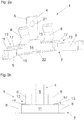
- Fig. 1a shows an assembly device 1, the assembly device 1 comprising two fastening devices 6, a spring device 7, two spring elements 8 and two holding devices 13, each with a floor covering web 17.
- the assembly device 1 comprises a spring support 12, the spring support 12 having a first support surface 11 which is arranged in the same plane as the at least one contact surface 5.
- the spring support 12 has a second support surface 20 which is spaced apart from the first support surface 11 by a material thickness of the spring support 12 and on which the spring device 7 is supported.
- the spring device 7 is designed as a separate component and is mounted together with the two spring elements 8 in or on the two holding devices 6 after a translational movement of the spring device 7 in the direction of the arrow.
- the holding device 13 is C-shaped in cross section.
- the spring device 7 is designed in the form of a bent leaf spring 22.
- the two fastening devices 6 are designed to be resilient.
- the assembly device 1 comprises a support device 4 with a contact surface 5 located on a rear side of the support device 4.
- the contact surface 5 is arranged laterally next to and between the two fastening devices 6.
- Figure 1b shows the assembly device 1 in a view from above in the direction of a substrate 16.
- the two spring elements 8 are in contact with a side surface 9 of a floor covering 10.
- a distance between the side surface 9 and a wall 3 is reduced, indicated by an arrow the two spring elements 8 and the spring device 7 in the form of the leaf spring 22 are elastically deformed.
- the assembly device 1 Due to the elastic deformation, indicated by a resilient movement, the assembly device 1 can be positioned in a fixed position between the wall and the floor covering. An elastically deformed state of the assembly device 1 is indicated in dash-dotted lines.
- the elastic deformation can have a degree at which a movement of the mounting device 1 along the side surface 9 is made possible.
- the distance between the side surface 9 and the wall 3 is particularly preferably predetermined.
- a user of the assembly device 1 can insert the assembly device 1 between the side surface 9 and the wall 3 by bending the spring elements 8 and / or the leaf spring 22.
- a terminating strip 2 (not visible for reasons of clarity) can then be placed on the assembly device 1.
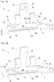
- Figure 1c shows the assembly device 1 in the position of use in a view from the side, the wall 3 and the floor covering 10 can be seen in a sectional view.
- the assembly device 1 is designed for assembly of the end strip 2.
- the end strip can be in the form of a skirting board or a wall end strip, for example.
- the support device 4 is supported on the wall 3, the support device 4 having a contact surface 5 brought flat against the wall 3.
- the assembly device 1 comprises a fastening device 6 which is designed in such a way that the end strip 2 to be assembled can be attached to the at least one fastening device 6 from above by a movement essentially parallel to the at least one contact surface 5 and in the position of use of the assembly device 1
- the assembly device 1 comprises the spring device 7 with the two spring elements 8, which are brought into connection with the side surface 9 of the floor covering 10, whereby the at least one contact surface 5 is pressed against the wall 3, the two spring elements 8 completely below the two fastening devices 6 are arranged.
- the second fastening device 6 is covered by the first fastening device 6 in the view.
- a spring support 12 which is arranged as an extension of the support device 4 and below the two fastening devices 6, is provided, which is also placed flat against the wall 3 and on which the spring device 7 is supported.
- the assembly device 1 has an underground web 15, the underground web 15 on the underground 16 running transversely to the wall 3 is brought flat to the system.
- the underground web 15 runs transversely to the contact surface 5 of the support device 4.
- the two floor covering webs 17 are brought flat against an upper side of the floor covering 10.
- the two floor covering webs 17 run transversely to the contact surface 5 of the support device 4.
- the underground web 15 and the two floor covering webs 17 are spaced apart from one another and are arranged essentially parallel to one another.
- the spring device 7 is arranged between the underground web 15 and the two floor covering webs 17.
- the fastening elements 2 comprise a curved profile part with a free upper end.
- the profile parts are brought into contact with a groove 24 in the end strip 2 via three contact lines 23.
- the two floor covering webs 17 and the subsurface web 15 promote the fixed positioning of the assembly device 1, since a contact between the subsurface web 15 and the subsurface 16 and / or a contact between the two floor covering webs 17 and an upper side 18 of the floor covering 10 is defined.
- Fig. 2a shows a mounting device 1, the spring device 7 having a centering element 19 for centering the spring device 7 relative to the mounting device 1.
- the at least one centering element 19 is arranged essentially parallel to the contact surface 5 and laterally next to and between the two fastening devices 6.
- the spring device 7 has a base 14 with a longitudinal extension and the centering element 19 is designed as a central web protruding transversely from the base 14.
- the centering element 19 is arranged laterally next to and between the two spaced-apart floor covering webs 17.
- Figure 2b shows the assembly device 1 from the rear, the first support surface 11 being arranged below the contact surface 5 of the support device 4 and the two fastening devices 6.
- the first support surface 11 and the contact surface 5 can be brought into flat contact with the wall when the assembly device is installed in the position of use.
- Fig. 3a shows a mounting device 1, the mounting device 1 being formed in one piece and the supporting device 4 having a fastening means 21 for fastening the mounting device 1 to the wall 3 (not visible in the illustration), the fastening means 21 being designed as an opening for receiving a screw.
- the fastening means 21 can generally also comprise, for example, a screw connection, an adhesive connection, a Velcro connection, a hook and / or a clamp.
- Figure 3b shows a mounting device 1, wherein no fastening means 21 is provided.
- the assembly device 1 can be used to assemble an end strip 2 (not shown in the illustration) without the aid of a tool.
- the second support surface 20 is arranged on the side of the base 14 pointing out of the plane of the drawing, the base 14 being part of the spring device 7. Due to the one-piece embodiment, the spring support 12 is formed by the base 14.
- the first support surface 11 is arranged on the rear side of the spring support 12 and lies in the same plane as the contact surface 5.
- the mounting device 1 is designed to be mirror-symmetrical about a vertical axis.
Landscapes
- Engineering & Computer Science (AREA)
- Architecture (AREA)
- Civil Engineering (AREA)
- Structural Engineering (AREA)
- Building Environments (AREA)
Priority Applications (1)
| Application Number | Priority Date | Filing Date | Title |
|---|---|---|---|
| EP19212568.0A EP3828362A1 (fr) | 2019-11-29 | 2019-11-29 | Dispositif de montage d'une réglette de raccordement |
Applications Claiming Priority (1)
| Application Number | Priority Date | Filing Date | Title |
|---|---|---|---|
| EP19212568.0A EP3828362A1 (fr) | 2019-11-29 | 2019-11-29 | Dispositif de montage d'une réglette de raccordement |
Publications (1)
| Publication Number | Publication Date |
|---|---|
| EP3828362A1 true EP3828362A1 (fr) | 2021-06-02 |
Family
ID=68732949
Family Applications (1)
| Application Number | Title | Priority Date | Filing Date |
|---|---|---|---|
| EP19212568.0A Withdrawn EP3828362A1 (fr) | 2019-11-29 | 2019-11-29 | Dispositif de montage d'une réglette de raccordement |
Country Status (1)
| Country | Link |
|---|---|
| EP (1) | EP3828362A1 (fr) |
Cited By (1)
| Publication number | Priority date | Publication date | Assignee | Title |
|---|---|---|---|---|
| AT524434B1 (de) * | 2021-02-01 | 2022-06-15 | Franz Neuhofer | Vorrichtung zur Befestigung einer Abschlussleiste |
Citations (4)
| Publication number | Priority date | Publication date | Assignee | Title |
|---|---|---|---|---|
| DE10107864A1 (de) * | 2001-02-20 | 2001-08-30 | Ernst Ruesch Gmbh | Halteelement für Abdeckleisten |
| WO2006105956A1 (fr) | 2005-04-05 | 2006-10-12 | Karl Pedross Ag | Dispositif pour fixer des baguettes de bord |
| DE102017103313A1 (de) | 2017-02-17 | 2018-08-23 | Kgm Holzerzeugnisse Gmbh | Vorrichtung zur werkzeuglosen Montage einer Abschlussleiste |
| DE102018119959A1 (de) * | 2018-08-16 | 2020-02-20 | Kgm Holzerzeugnisse Gmbh | Vorrichtung zur werkzeuglosen Montage einer Abschlussleiste |
-
2019
- 2019-11-29 EP EP19212568.0A patent/EP3828362A1/fr not_active Withdrawn
Patent Citations (4)
| Publication number | Priority date | Publication date | Assignee | Title |
|---|---|---|---|---|
| DE10107864A1 (de) * | 2001-02-20 | 2001-08-30 | Ernst Ruesch Gmbh | Halteelement für Abdeckleisten |
| WO2006105956A1 (fr) | 2005-04-05 | 2006-10-12 | Karl Pedross Ag | Dispositif pour fixer des baguettes de bord |
| DE102017103313A1 (de) | 2017-02-17 | 2018-08-23 | Kgm Holzerzeugnisse Gmbh | Vorrichtung zur werkzeuglosen Montage einer Abschlussleiste |
| DE102018119959A1 (de) * | 2018-08-16 | 2020-02-20 | Kgm Holzerzeugnisse Gmbh | Vorrichtung zur werkzeuglosen Montage einer Abschlussleiste |
Cited By (3)
| Publication number | Priority date | Publication date | Assignee | Title |
|---|---|---|---|---|
| AT524434B1 (de) * | 2021-02-01 | 2022-06-15 | Franz Neuhofer | Vorrichtung zur Befestigung einer Abschlussleiste |
| AT524434A4 (de) * | 2021-02-01 | 2022-06-15 | Franz Neuhofer | Vorrichtung zur Befestigung einer Abschlussleiste |
| US12460428B2 (en) | 2021-02-01 | 2025-11-04 | Franz Neuhofer | Device for fastening a finishing strip |
Similar Documents
| Publication | Publication Date | Title |
|---|---|---|
| EP2789931A1 (fr) | Dispositif de maintien pour la fixation d'un module de surface sur un support | |
| EP2270403A1 (fr) | Rail de support | |
| EP4175512B1 (fr) | Tiroir avec dispositif de maintien d'un panneau décoratif pouvant être placé sur la paroi latérale de tiroir | |
| EP1882793A2 (fr) | Elément d'aide au montage pour plaques, en particulier plaques de placoplâtre et/ou de carreaux de plâtre, tout comme agencement et procédé de montage correspondant | |
| EP2756238B1 (fr) | Dispositif de fixation d'un rail de montage sur un crochet de toit | |
| CH659509A5 (de) | Befestigungsmittel fuer die montage von tragvorrichtungen, insbesondere kabelkanaelen. | |
| EP2747598B1 (fr) | Dispositif de fixation pour la fixation mutuelle de deux éléments d'un élément de meuble | |
| EP2602555B1 (fr) | Système avec un appareil ménager, en particulier une plaque de cuisson, et au moins un dispositif de maintien de l'appareil ménager | |
| EP2206147A2 (fr) | Pince de fixation | |
| DE102016103169B4 (de) | Adapter zur Fixierung eines Bodens an einer Seitenzarge, Schubkasten und Verfahren zur Montage eines Bodens an einem Adapter | |
| EP3828362A1 (fr) | Dispositif de montage d'une réglette de raccordement | |
| DE20319556U1 (de) | Vorrichtung zum Verbinden eines Trägerteiles mit einem Anbauteil | |
| DE102018103311B3 (de) | Basisprofil einer Fußbodenprofilanordnung | |
| DE102016124988B4 (de) | Beschlag und Verfahren für das Verlegen von Terrassendielen | |
| WO2024016032A1 (fr) | Paroi latérale de tiroir | |
| EP1930525A2 (fr) | Dispositif de fixation d'une plinthe rainurée sur un mur | |
| EP3480390B1 (fr) | Revêtement de façade | |
| EP4030103B1 (fr) | Plaque de cuisson avec boîtier de commande | |
| DE202007008150U1 (de) | Befestigungsvorrichtung für Solarmodule | |
| EP3095949A1 (fr) | Dispositif de fixation d'un boîtier d'une plinthe d'étanchéité | |
| EP4558008B1 (fr) | Ensemble avec au moins un guide de tiroir coulissant | |
| EP3572595B1 (fr) | Pare-gravier | |
| DE8604895U1 (de) | Vorrichtung zur Befestigung einer Deckenabschlußleiste an einer Wand- und/oder Deckenvertäfelung | |
| DE2439692C3 (de) | Verbindungselement, insbesondere bei zweiteiligen verstellbaren Abhängern für Unterdecken, wobei beide Abhängerteile eine Lochreihe aufweisen | |
| DE102007051058A1 (de) | Befestigungsklammer und System zum Erstellen von Aufbauten |
Legal Events
| Date | Code | Title | Description |
|---|---|---|---|
| PUAI | Public reference made under article 153(3) epc to a published international application that has entered the european phase |
Free format text: ORIGINAL CODE: 0009012 |
|
| STAA | Information on the status of an ep patent application or granted ep patent |
Free format text: STATUS: REQUEST FOR EXAMINATION WAS MADE |
|
| 17P | Request for examination filed |
Effective date: 20200806 |
|
| AK | Designated contracting states |
Kind code of ref document: A1 Designated state(s): AL AT BE BG CH CY CZ DE DK EE ES FI FR GB GR HR HU IE IS IT LI LT LU LV MC MK MT NL NO PL PT RO RS SE SI SK SM TR |
|
| GRAP | Despatch of communication of intention to grant a patent |
Free format text: ORIGINAL CODE: EPIDOSNIGR1 |
|
| STAA | Information on the status of an ep patent application or granted ep patent |
Free format text: STATUS: GRANT OF PATENT IS INTENDED |
|
| INTG | Intention to grant announced |
Effective date: 20211118 |
|
| STAA | Information on the status of an ep patent application or granted ep patent |
Free format text: STATUS: THE APPLICATION IS DEEMED TO BE WITHDRAWN |
|
| 18D | Application deemed to be withdrawn |
Effective date: 20220329 |