EP3828359B1 - A roof window arrangement comprising a plurality of sash structures and a common frame, and including a covering assembly, and method of manufacturing such a roof window arrangement - Google Patents
A roof window arrangement comprising a plurality of sash structures and a common frame, and including a covering assembly, and method of manufacturing such a roof window arrangement Download PDFInfo
- Publication number
- EP3828359B1 EP3828359B1 EP20209938.8A EP20209938A EP3828359B1 EP 3828359 B1 EP3828359 B1 EP 3828359B1 EP 20209938 A EP20209938 A EP 20209938A EP 3828359 B1 EP3828359 B1 EP 3828359B1
- Authority
- EP
- European Patent Office
- Prior art keywords
- window unit
- frame
- window
- covering
- pane
- Prior art date
- Legal status (The legal status is an assumption and is not a legal conclusion. Google has not performed a legal analysis and makes no representation as to the accuracy of the status listed.)
- Active
Links
Images


Classifications
-
- E—FIXED CONSTRUCTIONS
- E04—BUILDING
- E04D—ROOF COVERINGS; SKY-LIGHTS; GUTTERS; ROOF-WORKING TOOLS
- E04D13/00—Special arrangements or devices in connection with roof coverings; Protection against birds; Roof drainage ; Sky-lights
- E04D13/03—Sky-lights; Domes; Ventilating sky-lights
-
- E—FIXED CONSTRUCTIONS
- E04—BUILDING
- E04D—ROOF COVERINGS; SKY-LIGHTS; GUTTERS; ROOF-WORKING TOOLS
- E04D13/00—Special arrangements or devices in connection with roof coverings; Protection against birds; Roof drainage ; Sky-lights
- E04D13/03—Sky-lights; Domes; Ventilating sky-lights
- E04D13/0305—Supports or connecting means for sky-lights of flat or domed shape
- E04D13/031—Supports or connecting means for sky-lights of flat or domed shape characterised by a frame for connection to an inclined roof
-
- E—FIXED CONSTRUCTIONS
- E04—BUILDING
- E04B—GENERAL BUILDING CONSTRUCTIONS; WALLS, e.g. PARTITIONS; ROOFS; FLOORS; CEILINGS; INSULATION OR OTHER PROTECTION OF BUILDINGS
- E04B7/00—Roofs; Roof construction with regard to insulation
- E04B7/18—Special structures in or on roofs, e.g. dormer windows
-
- E—FIXED CONSTRUCTIONS
- E04—BUILDING
- E04D—ROOF COVERINGS; SKY-LIGHTS; GUTTERS; ROOF-WORKING TOOLS
- E04D13/00—Special arrangements or devices in connection with roof coverings; Protection against birds; Roof drainage ; Sky-lights
- E04D13/03—Sky-lights; Domes; Ventilating sky-lights
- E04D13/0305—Supports or connecting means for sky-lights of flat or domed shape
-
- E—FIXED CONSTRUCTIONS
- E04—BUILDING
- E04D—ROOF COVERINGS; SKY-LIGHTS; GUTTERS; ROOF-WORKING TOOLS
- E04D13/00—Special arrangements or devices in connection with roof coverings; Protection against birds; Roof drainage ; Sky-lights
- E04D13/03—Sky-lights; Domes; Ventilating sky-lights
- E04D13/035—Sky-lights; Domes; Ventilating sky-lights characterised by having movable parts
- E04D13/0351—Sky-lights; Domes; Ventilating sky-lights characterised by having movable parts the parts pivoting about a fixed axis
- E04D13/0354—Sky-lights; Domes; Ventilating sky-lights characterised by having movable parts the parts pivoting about a fixed axis the parts being flat
-
- E—FIXED CONSTRUCTIONS
- E04—BUILDING
- E04D—ROOF COVERINGS; SKY-LIGHTS; GUTTERS; ROOF-WORKING TOOLS
- E04D13/00—Special arrangements or devices in connection with roof coverings; Protection against birds; Roof drainage ; Sky-lights
- E04D13/03—Sky-lights; Domes; Ventilating sky-lights
- E04D2013/034—Daylight conveying tubular skylights
Definitions
- the present invention relates to a roof window arrangement comprising a plurality of window units in a side-by-side configuration and a covering assembly including a set of coverings for each window unit, each window unit comprising at least one pane-carrying frame and a pane.
- the invention furthermore relates to a method of manufacturing a roof window arrangement.
- Roof windows to be installed in inclined roof surfaces come in a variety of types, and are either installed as stand-alone window units, in which all sides of the roof window borders on the roofing, or in configurations in which several window units are built together to combine into larger arrays providing a larger light influx into a room of a building, and in which only outer sides of the outermost window units border on the surrounding roofing.
- Typical configurations of twin or quadruple roof window arrangements installed side-by-side and/or above each other, respectively, are shown and described in Applicant's published international application WO 2004/055291 A1 and European patent No. EP 1 581 706 B1 .
- the window units are typically standard roof windows in which the right side frame member of the left-hand window unit is located adjacent to the left side frame member of the right-hand window unit, and/or the bottom frame member of the upper window unit is located adjacent to the top frame member of the lower window unit.
- a roof structure comprising rafters and battens
- at least one rafter and a number of battens will typically need to be removed to provide a sufficiently large aperture in the roof surface and roof structure
- specially designed gap trimmers are normally mounted between the window units and fastened to the roof structure in order to ensure sufficient strength and support for the roof window arrangement.
- CZ 280 295 B6 shows another example of a roof window arrangement.
- the standard roof windows constituting the window units of the prior art roof window arrangements are installed with a relatively small distance between adjacent side frame members, typically about 18 mm, which leaves sufficient space for trimmers etc.
- a covering assembly comprising a combination of flashing, cover and cladding elements which provide a weather-tight transition to the surrounding roofing and ensure tightness around each window unit and between adjacent window units.
- the prior art covering assemblies function well, they are dependent on a relatively large number of tailor-made components that must be manufactured, stored, transported, and assembled at the building site.
- the configuration may lead to a flexible roof window arrangement, where the roof windows can open independently from each other. Furthermore, this solution may enable thinner frames which improve the aesthetic appearance of the window and do not obstruct the outdoor view. It may also improve the daylighting conditions inside the room as the net glazing area may be increased.
- At least one window unit may comprise at least one side frame covering configured to function as a covering of a neighbouring window unit. This facilitates the easier assembly of the roof window arrangement.
- the side frame covering may comprise a snap lock part, which may allow for an easy mounting providing a snap effect.
- three window units are comprised including a first window unit with a pane-carrying frame in the form of an openable sash with a top member, two side members, and a bottom member, a second window unit with a fixed pane-carrying frame with a top member, two side members, and a bottom member, as well as a third window unit with a pane-carrying frame in the form of an openable sash with a top member, two side members, and a bottom member, such that the second window unit is positioned between the first window unit and the third window unit.
- the set of coverings associated to the second window unit may comprise two side frame coverings configured to function as a covering of the first window unit and the third window unit, preferably also a separate bottom pane-carrying frame covering. This minimizes the number of elements required for the roof window arrangement.
- the set of coverings associated to the first window unit and the third window unit each comprises two side sash coverings, of which the one side sash covering closest to the second window unit is configured to function as a covering of the second window unit.
- the set of hinges of each of the first window unit and the third window unit may comprise two sash hinge parts connected to the respective openable sash.
- Two frame hinge parts may be provided on the second window unit to act as a respective counterpart to the sash hinge part of the first window unit and the third window unit, respectively. This provides a stable and robust arrangement.
- Other types of fasteners such as latches, toggle clamps, case fittings, may also be comprised.
- a common frame may be provided to act as a single, stationary frame of all of the plurality of window units in side-by-side configuration, said common frame being configured to be built into a roof surface. Reduced manufacturing costs and frame profiles may be achieved due to the utilization of one single common frame for all the window units.
- the covering assembly comprises a top casing and two side frame coverings connected to the common frame.
- the common frame is provided with two frame hinge parts for the openable window units. This may allow for an openable window unit offering a flexible window solution.
- the covering assembly may comprise a top casing connected to the common frame and spanning all three window units, a first side frame covering and a fourth side frame covering connected to the common frame, a second side frame covering and a third side frame covering connected to the second window unit, and two side sash coverings connected to each of the first window unit and third window unit.
- each of the window units may be provided with a separate bottom sash or pane-carrying frame covering, more preferably also secondary side frame coverings and a secondary bottom frame covering. This embodiment may allow a more versatile solution with different possibilities of arranging the window units.
- the side frame coverings may act as claddings to the side sash coverings.
- the side frame coverings may be fixed, while the side sash coverings may comprise an openable portion that is tilted.
- At least one tower fitting may be connected to the second window unit to provide support for the top casing.
- Each tower fitting may comprise at least one screw tower and engagement means to engage with the second window unit.
- Tower fittings allow for a stable and secure connection to the window units.
- the screw tower may fixate and orientate the tower fitting on the second window unit.
- the tower fitting is a snap anchor fitting configured to cooperate with a snap lock part connected to the top casing.
- Other types of fittings may also be used, such as simpler clips or locks.
- the tower fitting may comprise both a snap anchor fitting and a screw tower fitting.
- the second window unit may comprise two frame members connected to the pane-carrying frame.
- the two frame members of the second window unit may extend between the top and the bottom of the common frame, preferably such that each frame member has a surplus length relative to the pane-carrying frame in order to allow accommodation of an end portion within the common frame. This leads to a more stable and robust connection with the common frame.
- each tower fitting may comprise a base with two upstanding screw towers and the engagement means may comprise two legs depending from the base and configured to straddle a frame member of the second window unit, preferably also an opening in the base to allow the introduction of fastening means. An easier assembly of the window units may thus be achieved.
- At least one cap member may be connected to the second window unit to provide a sealing at the bottom of the second window unit and the neighbouring first window unit and third window unit.
- Each cap member may comprise at least one flange to form a transition between the second window unit and the respective neighbouring first window unit and third window unit and engagement means to engage with the second window unit.
- each cap member may comprise a base from which the flange protrudes, an end portion depending from the base, and wherein the engagement means may comprise a leg depending from the base, a shoulder portion configured to abut a frame member of the second window unit, and a trough formed between an upstanding portion and the flange to interact with components of the second window unit.
- the components preferably may include a part of a bottom pane-carrying frame covering and a glazing bead.
- the cap member may comprise a first sealing portion and a second sealing portion configured to abut a frame member of the second window unit. This allows for a water tight arrangement, creating a sealing between the cap member and the window.
- the flange may allow the guidance of water away from the window.
- the flange may also be provided with a side wing, which may be formed as a protrusion being adjacent to the base.
- the side wing may create a seal between the cap member and the window and prevent water and/or wind from running and/or blowing into the construction along the flange.
- the flange may further comprise a front tower and/or a front wing, which may block water and/or wind from blowing into the construction.
- the cap member may also comprise a side tower being located adjacent to the second sealing portion, which may act as a wind breaker.
- the side tower may also act as a fixation between the cap member and the window improving the sealing.
- the cap member may comprise a top sealing flap, which may be provided adjacent to the upstanding portion.
- the top sealing flap may create a right angle with the upstanding portion and may comprise a guide tower.
- the guide tower may give stiffness to the top sealing flap and prevent wrong mounting of the gasket of the pane-carrying frame bottom member relative to the cap member.
- the cap member may comprise a side skirt extension adjacent to the leg, which may be dependent from the shoulder portion.
- a frame hinge part may be connected to a respective frame member of the second window unit to act as a respective counterpart to the sash hinge part of the first window unit and the third window unit, respectively.
- a frame hinge part may be connected to the common frame to act as a respective counterpart to the sash hinge part of the first window unit and the third window unit, respectively.
- the ratio between a second thickness of the combined thicknesses of a side member of the pane-carrying frame and the associated frame member of the second window unit as defined between an edge of the pane and an outer circumference of the frame member, and a corresponding thickness of a side member of the sash of the neighbouring first window unit or third window unit may lie in the range 1.2 to 2, preferably between 1.25 and 1.75, more preferably around 1.5.
- the ratio may lie in the range 1 to 1.2.
- a distance between panes of neighbouring windows may lie in the range 50 to 100 mm, more preferably around 75 mm.
- the sum of the first thickness and the second thickness may be about 90 to 99% of the distance between the panes.
- the overall appearance of the roof window arrangement may be slimmer, enhancing the view towards the exterior.
- the second side frame covering and the third side frame covering connected to the second window unit each have a width which may be larger than a predefined width of the first side frame covering and a fourth side frame covering connected to the common frame, preferably about 20 to 100% larger, more preferably about 50% larger.
- the width may also be 10 to 20% larger.
- said plurality of window units comprises three window units including a first window unit with a pane-carrying frame in the form of an openable sash with a top member, two side members, and a bottom member, a second window unit with a fixed pane-carrying frame with a top member, two side members, and a bottom member, and a third window unit with a pane-carrying frame in the form of an openable sash with a top member, two side members, and a bottom member, such that the second window unit is positioned between the first window unit and the third window unit, wherein a common frame is provided to act as a single, stationary frame of all of the plurality of window units in side-by-side configuration, said common frame being configured to be built into a roof surface, and wherein the openable sash of the first window unit
- a method of manufacturing a roof window arrangement is provided.
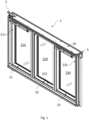
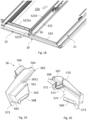
- a roof window arrangement 1 comprising a plurality of window units 21, 22, 23 configured side-by-side, and as seen from the interior of a room of a building with a roof surface (not shown), in which the roof window arrangement 1 is installed.
- three window units 21, 22, 23 are present, but other configurations are conceivable. For instance, two window units or any other number may be provided in the roof window arrangement.
- Each window unit 21, 22, 23 comprises a pane-carrying frame 211, 221, 231 and a pane 214, 224, 234.
- a common frame 10 acts as a single, stationary frame of all of the plurality of window units 21, 22, 23 in side-by-side configuration.
- the common frame 10 is configured to be built into the roof surface and connected to the underlying roof structure by means of a set of fittings represented by mounting bracket 3.
- a covering assembly generally designated 5 is shown as well.
- the covering assembly 5 provides covering for each window unit as will be described in further detail below.
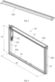
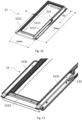
- Fig. 2 shows an embodiment of the covering assembly 5.
- the covering assembly 5 may be used in the roof window arrangement 1 of Fig. 1 .
- the covering assembly 5 comprises a top casing 510, a first side frame covering 511, a second side frame covering 512, a third side frame covering 513, and a fourth side frame covering 514.
- four side sash coverings 5211, 5212, 5231, 5232 are provided, and three separate bottom sash or pane-carrying frame covering 5213, 5223, 5233 in the embodiment shown.
- the covering assembly 5 may comprise further elements as well, including secondary frame coverings, and flashing elements.
- the top casing 510 of the covering assembly 5 in the embodiment shown is configured to be connected to a frame top member 11 of the common frame 10 and spanning all three window units 21, 22, 23 in the mounted condition.
- the first side frame covering 511 is connected to one frame side member 12 and the fourth side frame covering 514 is connected to another frame side member 13 of the common frame 10.
- a frame top member 11 extends between the frame side members 12, 13 at the top of common frame 10 as defined by the mounted condition of the roof window arrangement 10, and a frame bottom member 14 at the bottom.
- the dimensions of the window units forming part of the roof window arrangement may be chosen in accordance with specific installation conditions, including the area of the room of the building, the available roof surface etc.
- the overall outer measures of the common frame amount to a width wf of ca. 1840 mm and a height hf of 1180 mm, whereas three windows having the same size panes would have required a combined width about 2160 mm.
- the same pane area requiring only about 85% of the width of three windows installed side-by-side.
- a roof window arrangement comprising two window units having a larger individual width is considered; whereas two ordinary roof windows built in side-by-side would have required a combined width of 1740 mm, a roof window arrangement according to the invention would require only about 1496 mm, thus amounting to about 86% of width of two ordinary roof windows.
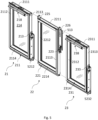
- the three window units 21, 22, 23 have the following configuration:
- the first window unit 21 has a pane-carrying frame in the form of an openable sash 211 with a top member 2111, two side members 2112 and 2113, and a bottom member 2114
- the second window unit 22 has a fixed pane-carrying frame 221 with a top member 2211, two side members 2212, 2213, and a bottom member 2214
- a third window unit 23 has a pane-carrying frame in the form of an openable sash 231 with a top member 2311, two side members 2312 and 2313, and a bottom member 2314.
- the second window unit 22 is positioned between the first window unit 21 and the third window unit 23.
- the openable sash 211, 231 of the first and third window units 21 and 23 opens about a hinge axis a (shown in Fig. 10 ) defined by a set of hinges 212, 213, 232, 233.
- the hinges may be of any suitable kind, here shown as pivot hinges as for instance disclosed in Applicant's EP 1 038 083 B1 , EP 1 781 883 B1 , EP 2 770 146 A1 and EP 2 770 149 A1 , or as a so-called pantograph hinge as described in Applicant's -pending international application WO 2017/076416 A1 .
- the set of hinges of each of the first window unit 21 and the third window unit 23 comprises two sash hinge parts 212, 213, 232, 233 connected to the respective openable sash 211, 231.
- the openable sash 211, 231 of the first window unit 21 and the third window unit 23 and the fixed pane-carrying frame 221 of the second window unit 22 are provided as substantially identical standard components.
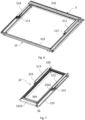
- the second window unit 22 comprises fixing means to fixate the pane-carrying frame 221 to the top member 11 and the bottom member 14 of the common frame 10.
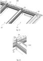
- the second side frame covering 512 and the third side frame covering 513 are connected to the second window unit 22 as shown in Fig. 7 , and two side sash coverings 5211, 5212 and 5231, 5232 are connected to a respective one of the first window unit 21 and third window unit 23.
- Each of the window units 21, 22, 23 is provided with a respective separate bottom sash or pane-carrying frame covering 5213, 5223, 5233.
- At least one of the side frame coverings 512, 513, 5212, 5231 of a set of coverings associated to one window unit 22, 21, 23 functions as a covering of that one window unit 22, 21, 23 and of a neighbouring window unit 21, 23, 22. All in all, four coverings are used rather than six (three times two) for each of the side sash coverings and the side frame coverings.
- the set of coverings associated to each window unit 21, 23 comprises two side sash coverings 5211, 5212 and 5231, 5232 to cover a lower portion of the respective sash 211, 231 from the hinges and downwards.
- a separate bottom sash covering 5213, 5233 is also shown.
- the side sash coverings 5211, 5212 and 5231, 5232 are configured to function as a covering of a neighbouring window unit, here of the second window unit 22 interposed between the first window unit 21 and the third window unit 23.
- the covering assembly 5 here also comprises secondary side frame coverings 531, 532 and a secondary bottom frame covering 533.
- flashing elements may be provided to ensure a weather-tightness transition to the surrounding roofing.
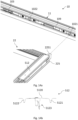
- the fixing means of the second window unit 22 comprises two frame members 225, 226 connected to the pane-carrying frame 221.
- the two frame members 225, 226 of the second window unit 22 extend between the top and the bottom of the common frame 10, such that each frame member 225, 226 has a surplus length relative to the pane-carrying frame 221 in order to allow accommodation of an end portion within the common frame 10.
- the frame hinge part 222, 223 is connected to a respective frame member 225, 226 of the second window unit 22 to act as a respective counterpart to the sash hinge part 213, 232 of the first window unit 21 and the third window unit 23, respectively.
- a frame hinge part 112, 113 is connected to the respective side members 12, 13 of the common frame 10 to act as a respective counterpart to the sash hinge part 212, 233 of the first window unit 21 and the third window unit 23, respectively.
- Fig. 9 it is illustrated how the window unit of Figs 7 and 8 is installed as a neighbouring window unit to an openable window unit of a roof window arrangement.
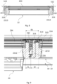
- the ratio t2 : t1 between a second thickness t2 of the combined thicknesses of a side member 2213 of the pane-carrying frame 221 and the associated frame member 225 of the second window unit 22 which is defined as between an edge of the pane 224 and an outer circumference of the frame member 225, and a corresponding thickness t1 of a side member 2312 of the sash 231 of the neighbouring first window unit or third window unit 23 lies in the range 1.2 to 2.
- the most preferred values of this range are between 1.25 and 1.75, and even more preferably around 1.5.
- a distance dp between panes 224, 234 of neighbouring windows lies in the range 50 to 100 mm, more preferably around 75 mm.
- the sum of the first thickness t1 and the second thickness t2 is about 90 to 99% of the distance dp between the panes
- the second side frame covering 512 and the third side frame covering 513 connected to the second window unit 22 both have a width which is larger than a predefined width of the first side frame covering 511 and a fourth side frame covering 514 connected to the common frame 10. This width is preferably about 20 to 100% larger, more preferably about 50% larger.
- these side frame coverings 512, 513 may take any suitable shape. However, for practical and aesthetic reasons, a substantially symmetrical design is preferred, for instance as shown in more detail in Fig. 14b , in which the side frame covering 512 is shown with a centre portion 5120 and a right-hand and a left-hand groove 5121 and 5122, respectively, which are located near the edge of the respective pane of the first and second window units 21 and 22.
- a snap lock part 5123 is fastened to the underside of the side frame covering 512.
- the snap lock part 5123 may for instance be formed as in the embodiment of Applicant's international published application WO 2013/050043 A1 . It is noted that such snap lock parts may be provided also on other components of the covering assembly 5.
- the gasket present at the sides of the window units could have an increased width relative to the gasket width of an ordinary window.
- an extra-wide gasket 2252 is indicated on the frame member 225 of the second window unit 22. Further details of this gasket are shown in Figs 26 and 27 .
- the frame top member 11 is provided with two apertures 1021 and 1022 to receive the frame members 225 and 226 (not visible in Fig. 14 ).
- frame member 225 comprises a protrusion 2251.
- Other details in Fig. 14a include a striking plate 103 for cooperating with locking means (not shown) of the first window unit 21, and an insulating element 109. These measures are well known to the skilled person.
- spacers 1023 are provided on the frame bottom member 14 for abutment of the bottom member 2214 in the mounted condition.
- FIG. 15 illustrates the upper part of the roof window arrangement, wherein a set of tower fittings 54 is connected to the second window unit 22 to provide support for the top casing 510.
- each tower fitting 54 comprises one screw tower 544, 545 and engagement means 542, 543, 546 to engage with the second window unit 22.
- Each tower fitting 54 comprises a base 541 with two upstanding screw towers 544, 545 and the engagement means comprise two legs 542, 543 depending from the base 541 and configured to straddle a frame member 225, 226 of the second window unit 22, and an opening 546 in the base 541 to allow the introduction of fastening means as shown in Fig. 16 .
- FIG. 17b and 17c An alternative tower fitting 54 is shown in Figs 17b and 17c , in which a snap anchor tower 547 is provided.
- the snap anchor tower 547 is configured to cooperate with a snap lock part (not shown) fastened to the top casing 510.
- the snap lock part may for instance have a configuration corresponding to the snap lock part 5123 connected to the side frame covering 512 of Fig. 14b .
- a set of tower fittings 54 and snap lock parts may be arranged over the width of the roof window arrangement.
- the tower fitting 54 of Fig. 17b has a base 541 intended to abut a window unit of the roof window arrangement.
- one tower fitting 54 is intended to abut the frame member 225, 226 of the second window unit 22, but additional or alternative positions are conceivable.
- An opening 546 is provided in the base 541 for receiving fastening means, here represented by a screw.
- an access opening 549 is provided, to give access to releasing the snap lock part interacting with a snap lock edge 5481 shown in Fig. 17c .
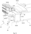
- Fig. 18 shows the lower part of the roof window arrangement and the provision of a cap member 56.
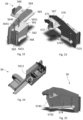
- Figs 19 and 20 show the cap member 56 of the roof window arrangement in more detail, which is connected to the second window unit 22 providing a sealing at the bottom of the second window unit 22 and the respective neighbouring first window unit 21 and third window unit 23.
- the cap member 56 is present in a left-hand and a mirror-inverted right-hand version. In the following, the cap member 56 at the transition between the second window unit 22 and the first window unit 21 will be described.
- Fig. 21 shows a perspective sectional view from another angle, showing the interaction between the cap member 56 and the bottom pane-carrying frame covering 5223.
- the cap member 56 comprises one flange 564 to form a transition between the second window unit 22 and the neighbouring first window unit 21 and engagement means to engage with the second window unit 22. Similar means may be provided at the other side.
- the position of the cap member 56 and flange 564 are also shown in Fig. 7 .
- the bottom covering 5223 of the pane-carrying frame of the second window unit 22 could from the outset be produced with side flanges, which are removed and replaced by the flange 564 of the cap member 56 at the respective end.
- the cap member 56 comprises a base 561 from which the flange 564 protrudes, an end portion 563 depending from the base 561, a first leg 562 and a second leg 574.
- the engagement means comprise the base 561, the first leg 562 and the second leg 574 are configured to abut the frame member 225.
- the cap member 56 is in the embodiment shown slid on the frame member 225 such that an entire end portion of the end member 225 is surrounded by the engagement means 561, 562, 563, 574.
- the frame member 225 is provided with an end portion (not shown in detail) with a lower height relative to the remaining portion of the frame member 225.
- a shoulder portion 565 is provided such that the shoulder portion 565 is located at a higher level than the base 561 and is connected to the base 561 via a step portion 5651.
- the cap member 56 also comprises a first bottom sealing flap 568 and a second bottom sealing flap 569 configured to abut the secondary bottom frame covering 533 of the covering assembly 5. Since the secondary bottom frame covering 533 in the embodiments shown is through-going, i.e. extends the full width of the three window units, the first and second bottom sealing flaps 568 and 569 abut the same element, thus providing a particularly tight connection.
- a trough 567 is formed between an upstanding portion 566 and the flange 564 to interact with components of the second window unit 22, including a part 5223a of the bottom pane-carrying frame covering 5223 and a glazing bead 5224, as shown in Fig. 18 .
- a sealing rib 570 is comprised in the trough 567 to enable a water tight connection.
- a top sealing flap 572 is also comprised in the cap member 56, which is adjacent to the upstanding portion 566. As shown in Fig. 21 , the top sealing flap 572 abuts the bottom pane-carrying frame covering 5223 in the mounted condition.
- the upstanding portion 566 of the trough 567 also comprises a guide tower 571 which provides stiffness to the top sealing flap 572.
- the flange 564 further comprises a front tower 573 at one end of it, which acts as blocking water and/or wind from blowing into the construction.
- the front tower 573 thus substantially blocks the slit formed between the bottom pane-carrying frame covering 5223 and the adjacent bottom sash covering 5213, when the first window unit 21 is in the closed position. Also visible in Fig. 21 are a gasket 2215 of the bottom member 2214 of the pane-carrying frame 221 of the second window unit 22 and an insulating element 2216.
- the gasket 2215 and the insulating element 2216 are known per se and are described in more detail in Applicant's German utility model DE 20 2012 009 491 U1 .
- the top sealing flap 572 provides a seal between the cap member 56 and the bottom pane-carrying frame covering 5223, and the guide tower 571 ensures correct mounting of the gasket 2215 relative to the cap member 56.
- a side tower 5741 is provided on the second leg 74.
- a first and a second side wing 5641 and 5642 are provided on the flange 564.
- a front wing 5631 is provided on the end portion 563 of the cap member 56.
- a fixation tower 5611 is present as shown in Fig. 24 .
- the second leg 574 has an extension portion 5742 and a rear rib 5743, both of which contributing to improving the sealing properties of the cap member 56.
- Figs. 26 and 27 show an alternative embodiment of the roof window arrangement, making use of a particular configuration of the gasket 2252 indicated schematically in Fig. 7 .
- the gasket 2252 extends between the lower end of the glazing bead 5224 of the second window unit 22 and up to a position at or near the frame hinge part 222 and provides a main sealing surface 2252a towards the side sash covering 5212 to block water entering into the window construction.
- the gasket 2252 is furthermore formed with a depending leg 2252b extending inwards from the main sealing surface 2252a and provided with an internal sealing profiling 2252c.
- an engagement flange 2252 is provided for engagement with the glazing bead 5224 and the right-hand side of which interacts with the cap member 56.
- a glazing bead 5214 of the first window unit 21 is also visible in Fig. 26.
Landscapes
- Engineering & Computer Science (AREA)
- Architecture (AREA)
- Civil Engineering (AREA)
- Structural Engineering (AREA)
- Physics & Mathematics (AREA)
- Electromagnetism (AREA)
- Wing Frames And Configurations (AREA)
- Body Structure For Vehicles (AREA)
- Roof Covering Using Slabs Or Stiff Sheets (AREA)
Applications Claiming Priority (1)
| Application Number | Priority Date | Filing Date | Title |
|---|---|---|---|
| DKPA201970740A DK180956B1 (en) | 2019-11-29 | 2019-11-29 | A roof window arrangement comprising a plurality of sash structures and including a covering assembly, and method of manufacturing such a roof window arrangement |
Publications (3)
| Publication Number | Publication Date |
|---|---|
| EP3828359A1 EP3828359A1 (en) | 2021-06-02 |
| EP3828359C0 EP3828359C0 (en) | 2024-10-30 |
| EP3828359B1 true EP3828359B1 (en) | 2024-10-30 |
Family
ID=73598691
Family Applications (1)
| Application Number | Title | Priority Date | Filing Date |
|---|---|---|---|
| EP20209938.8A Active EP3828359B1 (en) | 2019-11-29 | 2020-11-25 | A roof window arrangement comprising a plurality of sash structures and a common frame, and including a covering assembly, and method of manufacturing such a roof window arrangement |
Country Status (6)
| Country | Link |
|---|---|
| EP (1) | EP3828359B1 (pl) |
| CN (1) | CN112878598B (pl) |
| DK (1) | DK180956B1 (pl) |
| ES (1) | ES2999015T3 (pl) |
| HU (1) | HUE069733T2 (pl) |
| PL (1) | PL3828359T3 (pl) |
Families Citing this family (3)
| Publication number | Priority date | Publication date | Assignee | Title |
|---|---|---|---|---|
| DK181945B1 (en) * | 2022-03-31 | 2025-04-07 | Vkr Holding As | A roof window arrangement comprising a plurality of window units and a common frame, and method of installing such a roof window arrangement |
| EP4466420B1 (en) * | 2022-03-31 | 2025-01-22 | VKR Holding A/S | Roof window with a hinge assembly comprising a hinge unit and a coupling unit configured to assume at least one intermediate position and a final position |
| DK202370427A1 (en) * | 2023-08-21 | 2025-03-24 | Vkr Holding As | A roof window arrangement comprising a common stationary frame and at least a first window unit and a second window unit |
Citations (1)
| Publication number | Priority date | Publication date | Assignee | Title |
|---|---|---|---|---|
| CZ280295B6 (cs) * | 1991-08-12 | 1995-12-13 | P & Ac Investment A.S. | Střešní okno |
Family Cites Families (19)
| Publication number | Priority date | Publication date | Assignee | Title |
|---|---|---|---|---|
| GB2204627B (en) * | 1987-05-14 | 1991-07-10 | Frederick Sage Company Limited | Improvements in or relating to rooflights |
| DE9102461U1 (de) * | 1991-03-03 | 1991-05-23 | Lange, Edith, 2106 Bendestorf | Wetterschutzausrüstung für ein Dachflächenfenster |
| DK176024B1 (da) | 1997-11-11 | 2005-12-19 | Vkr Holding As | Hængselbeslag til et vippevindue |
| JP4384811B2 (ja) | 1998-04-07 | 2009-12-16 | ヴィーケーアール・ホールディング・アー・エス | 主枠およびサッシ被覆部材を備えた屋根窓 |
| PL247466B1 (pl) | 2002-12-16 | 2025-07-07 | Vkr Holding A/S | Boczny element obróbki blacharskiej |
| PL247467B1 (pl) | 2002-12-16 | 2025-07-07 | Vkr Holding A/S | Element obróbki blacharskiej wykonany z arkusza |
| CN2795390Y (zh) | 2004-07-02 | 2006-07-12 | Vkr控股公司 | 铰链装置 |
| PL217336B1 (pl) * | 2008-10-21 | 2014-07-31 | Fakro Pp Spółka Z Ograniczoną Odpowiedzialnością | Okno dachowe, zwłaszcza oddymiające, ze skrzydłem obrotowym |
| EP2460969B1 (en) * | 2010-12-03 | 2014-04-30 | Fakro PP Spolka Z O.O. | Double-sash roof window with side barriers |
| PL2472026T3 (pl) * | 2010-12-29 | 2019-01-31 | Vkr Holding A/S | System okienny mający konstrukcje ościeżnicy i skrzydła okiennego o smukłej budowie |
| PL401059A1 (pl) | 2011-10-04 | 2013-04-15 | Vkr Holding A/S | Okno dachowe z dolna uszczelka skrzydla i dolna uszczelka skrzydla |
| CA2849363C (en) | 2011-10-04 | 2016-11-08 | Vkr Holding A/S | A roof window with a covering fastening device |
| DK178257B1 (en) | 2013-02-22 | 2015-10-12 | Vkr Holding As | A pivot hinge fitting and a roof window comprising such a hinge fitting |
| DK177808B1 (en) | 2013-02-22 | 2014-07-21 | Vkr Holding As | A roof window having an improved lifting device and hinge connection |
| DK178524B1 (en) * | 2013-06-21 | 2016-05-23 | Vkr Holding As | A window arrangement comprising a plurality of window systems and at least one accessory element |
| SE539441C2 (sv) * | 2013-11-15 | 2017-09-26 | Arnby Bengt | System för montering av moduler |
| CH709523B1 (de) | 2014-04-01 | 2016-01-29 | Stebler Holding Ag | Gebäudeschrägdach mit Dachmodul. |
| DK179269B1 (en) | 2015-11-06 | 2018-03-19 | Vkr Holding As | A hinge for a roof window, and a roof window including a set of such hinges |
| DE202018100517U1 (de) | 2017-05-24 | 2018-07-12 | Vkr Holding A/S | Dachgaubenanordnung |
-
2019
- 2019-11-29 DK DKPA201970740A patent/DK180956B1/da active IP Right Grant
-
2020
- 2020-11-25 ES ES20209938T patent/ES2999015T3/es active Active
- 2020-11-25 PL PL20209938.8T patent/PL3828359T3/pl unknown
- 2020-11-25 EP EP20209938.8A patent/EP3828359B1/en active Active
- 2020-11-25 HU HUE20209938A patent/HUE069733T2/hu unknown
- 2020-11-27 CN CN202011355887.8A patent/CN112878598B/zh active Active
Patent Citations (1)
| Publication number | Priority date | Publication date | Assignee | Title |
|---|---|---|---|---|
| CZ280295B6 (cs) * | 1991-08-12 | 1995-12-13 | P & Ac Investment A.S. | Střešní okno |
Also Published As
| Publication number | Publication date |
|---|---|
| HUE069733T2 (hu) | 2025-04-28 |
| DK180956B1 (en) | 2022-08-11 |
| ES2999015T3 (en) | 2025-02-24 |
| EP3828359C0 (en) | 2024-10-30 |
| PL3828359T3 (pl) | 2025-03-03 |
| DK201970740A1 (en) | 2021-07-15 |
| CN112878598B (zh) | 2023-12-08 |
| EP3828359A1 (en) | 2021-06-02 |
| CN112878598A (zh) | 2021-06-01 |
Similar Documents
| Publication | Publication Date | Title |
|---|---|---|
| EP3828359B1 (en) | A roof window arrangement comprising a plurality of sash structures and a common frame, and including a covering assembly, and method of manufacturing such a roof window arrangement | |
| US9051775B2 (en) | Window having a sash and improved connection to the hinge | |
| US8800221B1 (en) | Vertical and sloped glazing framing members structured for electrical wiring | |
| KR102442044B1 (ko) | 힌지식 프로젝트 창이 구비된 단열 커튼월 | |
| CN112780004A (zh) | 一种应用于建筑物的墙单元及组合式墙体 | |
| EP3922781B1 (en) | A panel system with an installation profile having one or more border sections, and a method of adapting such a panel system | |
| KR101591862B1 (ko) | 커튼월과 스윙도어의 연결구조 | |
| JPS6227637Y2 (pl) | ||
| EP4257772B1 (en) | A roof window arrangement comprising a plurality of window units and a common frame, and method of installing such a roof window arrangement | |
| GB2145456A (en) | Roof light structure | |
| KR200375065Y1 (ko) | 시스템 창호의 조립식 창틀구조 | |
| CN214785206U (zh) | 一种密封垫圈和一种面板系统 | |
| KR100328412B1 (ko) | 격자식 이중창호용 후레임 | |
| CN213626242U (zh) | 一种面板系统 | |
| CN213979603U (zh) | 具有排水组件的面板系统 | |
| EP3795771B1 (en) | Skylight window | |
| US20200173224A1 (en) | Cover assembly for windows | |
| CN222595337U (zh) | 一种可开启的拱形天窗及其安装结构 | |
| JP6769736B2 (ja) | 太陽電池モジュールの配置構造 | |
| JP4580462B2 (ja) | バルコニ用サッシ体およびルーフバルコニ付き勾配屋根 | |
| JPS6129872Y2 (pl) | ||
| JP4543050B2 (ja) | 建物のルーフバルコニ | |
| CN113802781A (zh) | 具有带有安装型材和铰链的安装和铰链组件的面板系统 | |
| CN113802749A (zh) | 在包括多个面板的面板系统中使用的面板及其制造方法 | |
| JPS634780Y2 (pl) |
Legal Events
| Date | Code | Title | Description |
|---|---|---|---|
| PUAI | Public reference made under article 153(3) epc to a published international application that has entered the european phase |
Free format text: ORIGINAL CODE: 0009012 |
|
| STAA | Information on the status of an ep patent application or granted ep patent |
Free format text: STATUS: THE APPLICATION HAS BEEN PUBLISHED |
|
| AK | Designated contracting states |
Kind code of ref document: A1 Designated state(s): AL AT BE BG CH CY CZ DE DK EE ES FI FR GB GR HR HU IE IS IT LI LT LU LV MC MK MT NL NO PL PT RO RS SE SI SK SM TR |
|
| STAA | Information on the status of an ep patent application or granted ep patent |
Free format text: STATUS: REQUEST FOR EXAMINATION WAS MADE |
|
| 17P | Request for examination filed |
Effective date: 20211202 |
|
| RBV | Designated contracting states (corrected) |
Designated state(s): AL AT BE BG CH CY CZ DE DK EE ES FI FR GB GR HR HU IE IS IT LI LT LU LV MC MK MT NL NO PL PT RO RS SE SI SK SM TR |
|
| TPAC | Observations filed by third parties |
Free format text: ORIGINAL CODE: EPIDOSNTIPA |
|
| STAA | Information on the status of an ep patent application or granted ep patent |
Free format text: STATUS: EXAMINATION IS IN PROGRESS |
|
| 17Q | First examination report despatched |
Effective date: 20230707 |
|
| GRAP | Despatch of communication of intention to grant a patent |
Free format text: ORIGINAL CODE: EPIDOSNIGR1 |
|
| STAA | Information on the status of an ep patent application or granted ep patent |
Free format text: STATUS: GRANT OF PATENT IS INTENDED |
|
| INTG | Intention to grant announced |
Effective date: 20240702 |
|
| GRAS | Grant fee paid |
Free format text: ORIGINAL CODE: EPIDOSNIGR3 |
|
| GRAA | (expected) grant |
Free format text: ORIGINAL CODE: 0009210 |
|
| STAA | Information on the status of an ep patent application or granted ep patent |
Free format text: STATUS: THE PATENT HAS BEEN GRANTED |
|
| AK | Designated contracting states |
Kind code of ref document: B1 Designated state(s): AL AT BE BG CH CY CZ DE DK EE ES FI FR GB GR HR HU IE IS IT LI LT LU LV MC MK MT NL NO PL PT RO RS SE SI SK SM TR |
|
| REG | Reference to a national code |
Ref country code: GB Ref legal event code: FG4D |
|
| REG | Reference to a national code |
Ref country code: CH Ref legal event code: EP |
|
| REG | Reference to a national code |
Ref country code: DE Ref legal event code: R096 Ref document number: 602020040223 Country of ref document: DE |
|
| REG | Reference to a national code |
Ref country code: IE Ref legal event code: FG4D |
|
| U01 | Request for unitary effect filed |
Effective date: 20241030 |
|
| U07 | Unitary effect registered |
Designated state(s): AT BE BG DE DK EE FI FR IT LT LU LV MT NL PT RO SE SI Effective date: 20241106 |
|
| U20 | Renewal fee for the european patent with unitary effect paid |
Year of fee payment: 5 Effective date: 20241106 |
|
| PGFP | Annual fee paid to national office [announced via postgrant information from national office to epo] |
Ref country code: GB Payment date: 20241113 Year of fee payment: 5 |
|
| PGFP | Annual fee paid to national office [announced via postgrant information from national office to epo] |
Ref country code: CZ Payment date: 20241025 Year of fee payment: 5 |
|
| PGFP | Annual fee paid to national office [announced via postgrant information from national office to epo] |
Ref country code: ES Payment date: 20241210 Year of fee payment: 5 |
|
| PGFP | Annual fee paid to national office [announced via postgrant information from national office to epo] |
Ref country code: CH Payment date: 20241201 Year of fee payment: 5 |
|
| REG | Reference to a national code |
Ref country code: ES Ref legal event code: FG2A Ref document number: 2999015 Country of ref document: ES Kind code of ref document: T3 Effective date: 20250224 |
|
| PGFP | Annual fee paid to national office [announced via postgrant information from national office to epo] |
Ref country code: HU Payment date: 20241112 Year of fee payment: 5 |
|
| PG25 | Lapsed in a contracting state [announced via postgrant information from national office to epo] |
Ref country code: IS Free format text: LAPSE BECAUSE OF FAILURE TO SUBMIT A TRANSLATION OF THE DESCRIPTION OR TO PAY THE FEE WITHIN THE PRESCRIBED TIME-LIMIT Effective date: 20250228 Ref country code: HR Free format text: LAPSE BECAUSE OF FAILURE TO SUBMIT A TRANSLATION OF THE DESCRIPTION OR TO PAY THE FEE WITHIN THE PRESCRIBED TIME-LIMIT Effective date: 20241030 |
|
| PG25 | Lapsed in a contracting state [announced via postgrant information from national office to epo] |
Ref country code: NO Free format text: LAPSE BECAUSE OF FAILURE TO SUBMIT A TRANSLATION OF THE DESCRIPTION OR TO PAY THE FEE WITHIN THE PRESCRIBED TIME-LIMIT Effective date: 20250130 |
|
| PG25 | Lapsed in a contracting state [announced via postgrant information from national office to epo] |
Ref country code: GR Free format text: LAPSE BECAUSE OF FAILURE TO SUBMIT A TRANSLATION OF THE DESCRIPTION OR TO PAY THE FEE WITHIN THE PRESCRIBED TIME-LIMIT Effective date: 20250131 |
|
| PGFP | Annual fee paid to national office [announced via postgrant information from national office to epo] |
Ref country code: PL Payment date: 20241025 Year of fee payment: 5 |
|
| REG | Reference to a national code |
Ref country code: HU Ref legal event code: AG4A Ref document number: E069733 Country of ref document: HU |
|
| PG25 | Lapsed in a contracting state [announced via postgrant information from national office to epo] |
Ref country code: RS Free format text: LAPSE BECAUSE OF FAILURE TO SUBMIT A TRANSLATION OF THE DESCRIPTION OR TO PAY THE FEE WITHIN THE PRESCRIBED TIME-LIMIT Effective date: 20250130 |
|
| PG25 | Lapsed in a contracting state [announced via postgrant information from national office to epo] |
Ref country code: SM Free format text: LAPSE BECAUSE OF FAILURE TO SUBMIT A TRANSLATION OF THE DESCRIPTION OR TO PAY THE FEE WITHIN THE PRESCRIBED TIME-LIMIT Effective date: 20241030 |
|
| PG25 | Lapsed in a contracting state [announced via postgrant information from national office to epo] |
Ref country code: MC Free format text: LAPSE BECAUSE OF FAILURE TO SUBMIT A TRANSLATION OF THE DESCRIPTION OR TO PAY THE FEE WITHIN THE PRESCRIBED TIME-LIMIT Effective date: 20241030 |
|
| PG25 | Lapsed in a contracting state [announced via postgrant information from national office to epo] |
Ref country code: SK Free format text: LAPSE BECAUSE OF FAILURE TO SUBMIT A TRANSLATION OF THE DESCRIPTION OR TO PAY THE FEE WITHIN THE PRESCRIBED TIME-LIMIT Effective date: 20241030 |
|
| PLBE | No opposition filed within time limit |
Free format text: ORIGINAL CODE: 0009261 |
|
| STAA | Information on the status of an ep patent application or granted ep patent |
Free format text: STATUS: NO OPPOSITION FILED WITHIN TIME LIMIT |
|
| 26N | No opposition filed |
Effective date: 20250731 |
|
| PG25 | Lapsed in a contracting state [announced via postgrant information from national office to epo] |
Ref country code: IE Free format text: LAPSE BECAUSE OF NON-PAYMENT OF DUE FEES Effective date: 20241125 |
|
| U20 | Renewal fee for the european patent with unitary effect paid |
Year of fee payment: 6 Effective date: 20251008 |
|
| REG | Reference to a national code |
Ref country code: CH Ref legal event code: U11 Free format text: ST27 STATUS EVENT CODE: U-0-0-U10-U11 (AS PROVIDED BY THE NATIONAL OFFICE) Effective date: 20251201 |