EP3828332B1 - Method for feeding rectangular textile items to a treatment installation - Google Patents
Method for feeding rectangular textile items to a treatment installation Download PDFInfo
- Publication number
- EP3828332B1 EP3828332B1 EP20210309.9A EP20210309A EP3828332B1 EP 3828332 B1 EP3828332 B1 EP 3828332B1 EP 20210309 A EP20210309 A EP 20210309A EP 3828332 B1 EP3828332 B1 EP 3828332B1
- Authority
- EP
- European Patent Office
- Prior art keywords
- conveyor
- item
- clamp
- laundry
- periphery
- Prior art date
- Legal status (The legal status is an assumption and is not a legal conclusion. Google has not performed a legal analysis and makes no representation as to the accuracy of the status listed.)
- Active
Links
- 239000004753 textile Substances 0.000 title claims description 64
- 238000000034 method Methods 0.000 title claims description 15
- 238000009434 installation Methods 0.000 title claims 7
- 230000032258 transport Effects 0.000 claims description 34
- 238000003384 imaging method Methods 0.000 description 19
- 238000012546 transfer Methods 0.000 description 4
- 238000013461 design Methods 0.000 description 2
- 241000252169 Catostomus commersonii Species 0.000 description 1
- 241000124008 Mammalia Species 0.000 description 1
- 230000009194 climbing Effects 0.000 description 1
- 238000011156 evaluation Methods 0.000 description 1
- 238000005259 measurement Methods 0.000 description 1
- 238000012545 processing Methods 0.000 description 1
- 230000000284 resting effect Effects 0.000 description 1
- 238000000926 separation method Methods 0.000 description 1
- 238000011144 upstream manufacturing Methods 0.000 description 1
Images


Classifications
-
- D—TEXTILES; PAPER
- D06—TREATMENT OF TEXTILES OR THE LIKE; LAUNDERING; FLEXIBLE MATERIALS NOT OTHERWISE PROVIDED FOR
- D06F—LAUNDERING, DRYING, IRONING, PRESSING OR FOLDING TEXTILE ARTICLES
- D06F67/00—Details of ironing machines provided for in groups D06F61/00, D06F63/00, or D06F65/00
- D06F67/04—Arrangements for feeding or spreading the linen
-
- D—TEXTILES; PAPER
- D06—TREATMENT OF TEXTILES OR THE LIKE; LAUNDERING; FLEXIBLE MATERIALS NOT OTHERWISE PROVIDED FOR
- D06F—LAUNDERING, DRYING, IRONING, PRESSING OR FOLDING TEXTILE ARTICLES
- D06F93/00—Counting, sorting, or marking arrangements specially adapted for laundry purposes
-
- D—TEXTILES; PAPER
- D06—TREATMENT OF TEXTILES OR THE LIKE; LAUNDERING; FLEXIBLE MATERIALS NOT OTHERWISE PROVIDED FOR
- D06F—LAUNDERING, DRYING, IRONING, PRESSING OR FOLDING TEXTILE ARTICLES
- D06F95/00—Laundry systems or arrangements of apparatus or machines; Mobile laundries
Definitions
- the invention relates to a method for feeding rectangular textile objects to a treatment device according to the preamble of claim 1.
- Textile objects in particular items of laundry to be washed and/or washed, with a rectangular shape must be gripped in such a way that they can be fed to a treatment facility. This applies to rectangular textile objects that have edges of the same length or of unequal length at right angles to one another.
- the DE 39 12 977 A1 discloses a method and apparatus for feeding rectangular laundry items to a mangle. As in the previously described prior art, two clamps grip a corner and a spaced location of the item of laundry, so that the clamps hold a horizontal section of an edge of the item of laundry. This creates a vertical edge under the held corner of the item of laundry, the length of which is determined.
- the invention is based on the object of creating a method for the rapid and reliable automatic feeding of rectangular textile objects to treatment facilities.
- a method for solving the problem has the measures of claim 1.
- the textile object with the gripped one Section of its edge is specifically fed across or along the processing device, preferably pulled onto a conveyor that transports the textile object to a treatment device.
- the textile object is to be pulled onto the conveyor in such a way that a short edge runs transversely to the transport direction and/or longitudinal direction of the conveyor, an object gripped by a section of its short edge is pulled onto the conveyor lengthwise in the transport direction, while a with A textile object gripped on a section of a long edge is pulled across the conveyor. If it is determined that the rectangular object is a square object with edges of the same length, this textile object can be pulled onto the conveyor lengthwise or crosswise as desired.
- the method preferably works with at least one imaging device.
- This allows the respective textile object to be at least partially measured. For example, from a recording of at least a relevant part of the textile object, preferably of the entire textile object, generated by the imaging device, it can be derived which edge is the shorter or the longer. In the same way, it can be determined whether both edges of square textile objects are the same length or at least almost the same length.
- image data generated by an imaging device can also serve for other or additional purposes, for example in particular to specifically move the clip or double clip for detecting an edge section of the respective textile object to the location of the edge whose section is to be detected.
- a portion of this edge is gripped by a clip.
- This is preferably a double clamp with two spaced clamps, between which the edge section or at least a part thereof is fixed in a stretched manner, or an elongated clamp, the length of which corresponds to the length of the section of the edge of the laundry item to be gripped.
- the textile object of this clamp or double clamp is placed on or over the conveyor to feed the textile object to a treatment facility.
- This is preferably done in such a way that the textile object is pulled over the conveyor in an inverted U-shaped configuration.
- the conveyor is narrower than the shorter edge of the textile object.
- Opposite edge regions of the textile object then hang down from opposite sides of the conveyor, with an intermediate inner section, preferably central section, of the textile object then resting on the upper run of the narrow conveyor.
- the at least one imaging device is assigned to the wall. This assignment is preferably carried out in such a way that the at least one imaging device is directed at at least part of the textile object hanging in front of the wall and/or at least such image data can be generated by the imaging device, from which it can be deduced whether from the one upper corner area or one A long edge or a short edge hangs down from the upper corner of the textile object, or both edges of the textile object are at least approximately the same length.
- This design of the device enables rapid, reliable and precise automatic gripping, in particular of rectangular textile objects.
- the prerequisite is created so that textile objects can be grabbed either fully automatically to be fed directly to a treatment device for the textile objects or to a preferably narrow conveyor in front of a treatment device, preferably to be put on and/or deposited thereon.
- the single imaging device or possibly also a separate imaging device can also serve to determine the length of the item of laundry hanging down from the held upper corner. This is preferably the distance between diagonally opposite corners of the item of laundry, namely the held upper corner and the free lower corner located at the lowest point of the hanging item of laundry.
- the length of the item of laundry can be used to roughly determine its size. Accordingly, it can be specified how far along the oblique path to which the holding means is assigned the suction cup of the holding means can be moved without the risk of the suction-held textile object becoming detached from the suction device.
- the imaging device can also serve to observe how the length of the edge of the textile object hanging down from the held upper corner changes when it is reoriented by the holding means, namely the suction cup and the gripper thereof. If necessary, the reorientation of the textile object can also be stopped when the imaging device determines that the hanging edge starting from the held upper corner of the textile object has developed to a sufficient length.
- the device shown in the figures and the method that can be carried out with it serve to automatically grip rectangular textile objects and preferably also to automatically feed such textile objects to a treatment device.
- the laundry items 10 preferably relate to so-called flat laundry items, such as. E.g. tablecloths, napkins, bed sheets, duvet covers and/or pillowcases.
- the rectangular laundry items 10 usually have edges of unequal length, in that two parallel edges are larger than two parallel edges running transversely thereto.
- the laundry items 10 can also be square with four edges of equal length. In the figures, the vertical edges are the longer edges. They are referred to as longitudinal edges 11, while the horizontal edges are the shorter edges referred to as transverse edges 12.
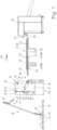
- Fig. 1 shows schematically an automatically operating separator 13.
- the separator 13 automatically grabs, preferably a single item of laundry 10 from a pile of laundry 14.
- the targeted automatic grabbing of ideally a single item of laundry 10 takes place - supported by at least one camera 15 or another imaging device - in in the vicinity of the pile of laundry 14.
- An image evaluation device controls a gripper 16 of the automatic separator 13 that can be moved up and down along a climbing path based on the at least one recording of the camera 15.
- the gripper 16 preferably transfers what it has grabbed individual item of laundry 10 to a subsequent provision device 17 of the separator 13.
- This takeover is carried out by a clamp 19 of the device of the invention which follows in the transport direction 20, namely the laundry flow direction and/or feed direction.
- the clamp 19 can also grip a corner area of the corner 18. Even if only the corner 18 is mentioned in the description, this should also include a corner area around the corner 18.
- the conveyor 21 which transports the laundry items 10 further.
- the conveyor 21 is formed from a conveyor cascade 22.
- the conveyor cascade 22 consists of several pairs of belt conveyors 23 arranged in a sandwich-like manner one above the other in the transport direction 20. Between these belt conveyors 23 arranged one above the other, namely the strand directed towards one another, the laundry items 10 can be transported in the transport direction 20 along the conveyor cascade 22 to one of these subsequent input machines 24 .
- the initial pair of belt conveyors 23 lying one above the other in the conveyor cascade 22 is of different lengths.
- the lower belt conveyor 23 is longer than the upper belt conveyor 23 above it.
- the respective item of laundry 10 is placed in the transport direction 20 depending on the orientation pulled onto the storage area 25 or pulled across the storage area 25, after which the respective item of laundry 10 rests in an inverted U-shaped configuration on the storage area 25 at the beginning of the conveyor cascade 22.
- This U-shaped configuration of the item of laundry 10 placed on the storage area 25 comes about because the belt conveyors 23 are relatively narrow, namely have a width which, depending on the size of the item of laundry 10, corresponds to one to five tenths of the width of the same.
- opposite outer edge regions of the item of laundry 10 in the area of the storage area 25 hang down from opposite sides of the belt conveyor 23 to form ideally, but not necessarily, equally long legs of the U-shaped configured item of laundry 10.
- a central one lying between the legs or outer edge areas preferably The central area of the item of laundry 10, which connects the opposite legs like a web, rests on the storage area 25.
- Upper and lower belt conveyors 23 of the conveyor cascade 22, which follow one another in the transport direction 20, are driven at transport speeds that differ from one another and increase at the same rate in the transport direction 20, which means that when the respective item of laundry 10 passes through the conveyor cascade 22, i.e. the further transport of the item of laundry 10 along the conveyor 21 in the transport direction 20 , the item of laundry 10 is stripped out in the transport direction 20, so that at the end of the conveyor 21, i.e. the last belt conveyor 23 of the conveyor cascade 22, the respective item of laundry 10 is at least largely stretched out in the transport direction 20 in an inverted U-shape over the last lower belt conveyor 23 of the conveyor cascade 22 is located.
- the conveyor 21 is also conceivable, in which it is not formed from a conveyor cascade 22 and/or no belt conveyors 23 are arranged sandwich-like one above the other.
- the conveyor 21 then consists of a single continuous conveyor on which the respective item of laundry 10 is placed or pulled up, preferably in an inverted U-shaped configuration. If necessary, several shorter lower belt conveyors can follow one another. These can also have different transport speeds, preferably those that increase in the transport direction 20.
- the conveyor 21 is followed by the input machine 24.
- the input machine 24 shown has a loading station, which in the exemplary embodiment shown has a loading conveyor 27, which extends the conveyor cascade 22 of the conveyor 21 in the transport direction 20 and also two belt conveyors 28 arranged one above the other in a sandwich-like manner has.
- the belt conveyors 28 have a width that corresponds to that of the belt conveyors 23 and are therefore also relatively narrow.
- a device according to the invention and/or a subsequent conveyor 21 are assigned at least for each loading station.
- three devices and three conveyors 21 are then provided in front of the input machine 24, so that each device and each conveyor is used to load, namely feed, laundry items 10 to a loading station of the input machine 24.
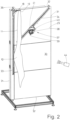
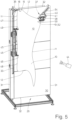
- the device has a vertical wall 29 in the exemplary embodiment shown. If necessary, the wall 29 can also run upright with its front side 30 slightly inclined.
- the rectangular wall 29 is preferably arranged in a stationary manner between the supply device 17 of the separator 13 and the conveyor 21. If necessary, the wall 29 can also be movable.
- the upright wall 29 has a rectangular base area with upright, longer longitudinal edges 31 and shorter, horizontal transverse edges 32. The base area of the front 30 of the wall 29 is dimensioned such that the largest items of laundry 10 to be processed can hang in front of it.
- the wall 29 is assigned a vertical, rectilinear rail 33 and an oblique, rectilinear rail 34, which runs at a short distance parallel to the left-hand longitudinal edge 31 in relation to the figures.
- the rails 33 and 34 are embedded in the wall 29, but are open or exposed to the front 30 of the wall 29.
- the oblique rail 34 has a lower end next to the vertical rail 33 and a higher, opposite end.
- the lower end of the obliquely directed straight rail 34 is located approximately halfway up the vertical rail 33, preferably slightly below.
- the higher opposite end of the oblique rail 34 is located in an upper right corner area of the front 30 of the wall 29. This is the side of the wall 29 that is opposite the vertical rail 33.
- the already mentioned clamp 19 can be moved up and down on a clamp carriage 36.
- the clamp 19 is attached to the clamp carriage 36 pointing transversely to the inclined rail 34, in such a way that the clamp mouth of the clamp 19 can be moved up and down at a short distance in front of the front 30 of the wall 29.
- a holding means 37 can be moved in opposite directions along the oblique rail 34.
- the holding means 37 has two independently operating holding means for the item of laundry 10, one pneumatic with negative pressure working suction cup 38 and a mechanical gripper 39.
- the suction cup 38 and the gripper 39 are fastened together to a carriage 40 which can be moved along the rail 34. This attachment is done in such a way that the suction direction of the suction cup 38 and the mouth of the gripper 39 run parallel to the wall 29, at a short distance in front of the front side 30 of the wall 29.
- Both the suction cup 38 and the gripper 39 are parallel to one another in this way oriented that the suction direction of the suction cup 38 and the mouth of the gripper 39 run parallel to the transverse edges 32 of the wall 29 or the front side 30 of the same. It is conceivable to fasten the suction cup 38 and/or the gripper 39 on a common support plate 41, which can be rotated freely and/or in a targeted manner about an axis of rotation running perpendicular to the plane of the front side 30 of the wall 29 in order to adapt to the orientation of the Suction cup 38 and gripper 39 to be detected in the area of the item of laundry 10, in particular areas 42 and 43 of the item of laundry that are close to one another.
- At least one imaging device is assigned to the device. This assignment is made in such a way that the imaging device is directed at the front 30 of the wall 29 in order to provide an image of at least one part of the item of laundry 10 hanging down in front of the wall 29 that provides the desired information.
- the at least one imaging device preferably serves to capture the entire item of laundry 10 or at least a large part of it in front of the wall 29 and to generate at least one image of it.
- the imaging device is preferably a camera 44.
- the camera 44 can be designed as a black and white camera or as a color camera that generates two- or three-dimensional images.
- At least one further imaging device which can also be designed as a camera, at at least one other location in front of or next to the wall 29.
- Such an imaging device can additionally record at least one image from a different viewing direction of the item of laundry 10 hanging down in front of the wall 29 or desired details thereof.
- the device also has a clamp 45 or such a clamp 45 is assigned to the device.
- This clamp 45 is designed to grip a section of the edge hanging freely under the clamp 19, which can be a longitudinal edge 11 or a transverse edge 12.
- the clip 45 grips a section 46 of the left longitudinal edge 11 of the item of laundry 10, which hangs freely from the clip 19.
- This section 46 lies between two end sections 47 and 48 extending from adjacent corners of the freely hanging longitudinal edge 11.
- the clip 45 can grip the inner or approximately central section 46 of the edge of the item of laundry 10 hanging freely from the clip 19, in the device shown it is designed as a double clip with two spaced-apart individual clips 49.
- the distance between the individual clips 49 corresponds to the length of the section 46 of the vertically hanging edge of the item of laundry 10 to be gripped by the clip 45.
- the clip 45 it is also conceivable to design the clip 45 as an elongated clip, the clip mouth of which is so long that it is extends over the entire section 46 of the vertically hanging edge to be gripped, here the longitudinal edge 11, of the item of laundry 10.
- the clamp 45 is arranged at the end of an arm of a handling device.
- the handling device is designed in such a way that the clamp 46 can be moved by it, in particular its arm, in at least three axes in three-dimensional space.
- the clamp 45 is arranged so that it can be rotated and/or pivoted in a targeted manner at the end of the arm of the handling device.
- the handling device transfers the respective item of laundry 10 from the point at which it is gripped by the clamp 45 in front of the wall 29 to the deposit area 25 of the conveyor 21 in front of the input machine 24
- the handling device is designed as a robot 50.
- the handling device can also be designed like a crane.
- the movements of the handling device, in particular the robot 50, are controlled based on the image data recorded by the at least one imaging device, in particular camera 44.
- the movements of the suction cup 38 and/or the gripper 39 can also be controlled based on the image data supplied by the camera 44 or another imaging device. This also applies to the time at which the item of laundry 10 is grabbed by the gripper 39 and the suction cup 38 is deactivated and/or the holding means 37 is moved along the inclined rail 34.
- the item of laundry 10 is an item of laundry that has shorter transverse edges 12 compared to the longitudinal edges 11, the item of laundry 10 with transverse to the The transverse edge 12 running in the transport direction 20 is pulled onto the support area 25 of the conveyor 21 and the item of laundry 10 hangs down from the clamp 19 with the (longer) longitudinal edge 11.
- a piece of laundry 10 separated by the separator 13 is held ready by the provision device 17 of the separator 13 for acceptance by the clamp 19 of the device or the laundry item 10 is transferred from the provision device 17 to the clamp 19.
- the item of laundry 10 is taken over or handed over to the clamp 19 in such a way that the clamp 19 of the device holds the item of laundry in a corner area, in particular a first corner 18.
- the clamp 19 can assume a position on the straight vertical rail 33 that allows or favors the handover or taking over of the corner 18 of the item of laundry 10 from the clamp 19.
- the clamp 19 is raised along the vertical, straight rail 34 to such an extent that the item of laundry 10 hangs freely from the first corner 18 held in the clamp 19. It is preferably provided that the first clamp 19 is raised to the upper end of the vertical rail 33 in order to take over the item of laundry 10.
- the camera 44 directed at the item of laundry 10 in front of the wall 29 provides images that can be used to control the travel path of the clamp 19 and the holding means 37.
- the images or image data from the camera 44 can alternatively or additionally also serve to control the opening and closing of the clamp 19 and/or the suction cup 38 and the gripper 39 of the holding means 37. In particular, this makes it possible to control when the gripper 39 grips the location 43 of the item of laundry 10 and when the vacuum cleaner 38 releases the location 42 of the item of laundry 10 that it has grasped.
- the images of the item of laundry 10 recorded at least by the camera 44 directed at the item of laundry 10 and the wall 29, in particular image data of the images, are preferably also used to determine whether the edge of the item of laundry 10 hanging down from the clip 19 is a longitudinal edge 11 (as assumed in the description above and below) or a transverse edge 12. To determine the longitudinal edge 11 and the transverse edge 12, the exact length dimensions of the same cannot be determined. It is sufficient to carry out a qualitative measurement, which makes it possible to distinguish between the longitudinal edge 11 and the transverse edge 12 or to determine whether both edges of square laundry items 10 are of the same length.
- the front side 30 of the wall 29 with a grid, in particular a checkerboard-like grid, whereby the length dimensions of the longitudinal edge 11 and the transverse edge 12 can be determined and, if necessary, the size of the respective item of laundry 10 can also be determined mathematically.
- the robot 50 or a comparable handling device for moving the clamp 45 is also controlled at least for gripping the inner, preferably central, section 46 of the longitudinal edge 11 hanging down from the clamp 19 on the basis of the images recorded by the camera 44 and/or its image data.
- the opening and closing of the clamp 45 can also be controlled.
- the control of the robot 50 and the clamp 45 is supplied with the images or image data recorded by the camera 44.
- the robot 50 then moves the clamp 45 to the inner or central section 46 of the vertically hanging longitudinal edge 11 of the item of laundry 10.
- the first corner 18 is released by opening the clamp 19 and the opposite second corner 52 is also preferably released from the gripper 39 of the holding means 37.
- the item of laundry 10 then hangs down on the clip 45 designed as a double clip or wide clip, with the central section 46 of the longitudinal edge 11 being held stretched between the individual clips 49 of the clip 45 or a wide clip.
- the clip 45 with the item of laundry 10 hanging on it is then transferred from the robot 50 or another handling device to the conveyor 21 in front of the input machine 24.
- the clamp 45 holds a central, in particular central, section 46 of the longitudinal edge 11 of the item of laundry 10, when the item of laundry 10 is fed with the transverse edge 12 running transversely to the transport direction 20, as is assumed here, the item of laundry 10 is moved by the robot 50 transversely to the transport direction 20 over the Deposit area 25 of the conveyor 21 is pulled onto this one exposed upper run of the lower front belt conveyor 28 of the same.
- the clamp 45 is designed to be so wide that the section 46 it holds is slightly larger than the width of the belt conveyor 28 in the deposit area 25.
- the robot 50 would move the clamp 45 in such a way that the item of laundry 10 is pulled onto the deposit area 25 of the conveyor 21 in the transport direction 20, with the clamp 45 moving with the of its held section 46 of the transverse edge 12 of the item of laundry 10 is moved centrally in the transport direction 20 over the storage area 25.
- the item of laundry 10 hangs in an inverted U-shaped configuration in the storage area 25 above the front, lower belt conveyor due to the relatively narrow belt conveyors 28 to form the conveyor 21 28.
- at least the inner, preferably middle, section 46 of the item of laundry 10, originally held by the clamp 19 extends over the deposit area 25 of the loading conveyor 27, while edge sections of the item of laundry 10 adjoining the section 46 on both sides are on both sides of the deposit area 25 of the conveyor 21 hanging down.
- the item of laundry 10 is transported by the conveyor 21, in particular its belt conveyors 28, in the transport direction 20 to the input machine 24 and preferably stretched out in the transport direction 20, so that the item of laundry 10, which is at least wrinkle-free or at least virtually wrinkle-free as seen in the transport direction 20, can be transferred from the conveyor 21 to the respective loading conveyor 27 of the input machine 24, in the now extended but still inverted U-shaped configuration.
- ⁇ b>Reference symbol list ⁇ /b> 10 item of laundry 47 End section 11 Longitudinal edge 48 End section 12 Transverse edge 49 Single bracket 13 Singler 50 robot 14 Laundry pile 51 Position 15 camera 52 second corner 16 Grabber 17 Deployment facility 18 first corner 19 bracket 20 Transport direction 21 Sponsor 22 Funder cascade 23 Belt conveyor 24 Input machine 25 Drop-off area 27 loading conveyor 28 Belt conveyor 29 Wall 30 front 31 Longitudinal edge 32 Transverse edge 33 rail 34 rail 36 Clamp carriage 37 Holding means 38 Mammal 39 Grabber 40 Carriage 41 support plate 42 Job 43 Job 44 camera 45 bracket 46 Section
Description
Die Erfindung betrifft ein Verfahren zum Zuführen rechteckiger textiler Gegenstände zu einer Behandlungseinrichtung gemäß dem Oberbegriff des Anspruchs 1.The invention relates to a method for feeding rectangular textile objects to a treatment device according to the preamble of
Textile Gegenstände, insbesondere zu waschende und/oder gewaschene Wäschestücke, mit einer rechteckigen Gestalt müssen so ergriffen werden, dass sie einer Behandlungseinrichtung zuführbar sind. Das gilt sowohl für rechteckige textile Gegenstände, die gleich lange oder ungleich lange rechtwinklig zueinander verlaufende Ränder aufweisen.Textile objects, in particular items of laundry to be washed and/or washed, with a rectangular shape must be gripped in such a way that they can be fed to a treatment facility. This applies to rectangular textile objects that have edges of the same length or of unequal length at right angles to one another.
Es ist aus der
Die
Der Erfindung liegt die Aufgabe zugrunde, ein Verfahren zum raschen und zuverlässigen automatischen Zuführen rechteckiger textiler Gegenstände zu Behandlungseinrichtungen zu schaffen.The invention is based on the object of creating a method for the rapid and reliable automatic feeding of rectangular textile objects to treatment facilities.
Ein Verfahren zur Lösung der Aufgabe weist die Maßnahmen des Anspruchs 1 auf.A method for solving the problem has the measures of
Bei diesem Verfahren ist es vorgesehen, dass vor oder nach dem Greifen eines Abschnitts eines Rands des textilen Gegenstands ermittelt wird, ob es sich bei dem ergriffenen Rand um einen kurzen oder langen Rand handelt und in Abhängigkeit vom Ergebnis dieser Ermittlung der textile Gegenstand mit dem ergriffenen Abschnitt seines Rands gezielt quer oder längs der Bearbeitungseinrichtung zugeführt wird, vorzugsweise auf einen den textilen Gegenstand zu einer Behandlungseinrichtung transportierenden Förderer aufgezogen wird.In this method it is provided that before or after gripping a section of an edge of the textile object it is determined whether the gripped edge is a short or long edge and, depending on the result of this determination, the textile object with the gripped one Section of its edge is specifically fed across or along the processing device, preferably pulled onto a conveyor that transports the textile object to a treatment device.
Wenn zum Beispiel der textile Gegenstand so auf den Förderer aufgezogen werden soll, dass ein kurzer Rand quer zur Transportrichtung und/oder Längsrichtung des Förderers verläuft, wird ein mit einem Abschnitt seines kurzen Rands erfasster Gegenstand längs in Transportrichtung auf den Förderer aufgezogen, während ein mit einem Abschnitt eines langen Rands ergriffener textiler Gegenstand quer über den Förderer gezogen wird. Wird ermittelt, dass es sich beim rechteckigen Gegenstand um einen quadratischen Gegenstand mit gleich langen Rändern handelt, kann dieser textile Gegenstand beliebig längs oder quer auf den Förderer aufgezogen werden.If, for example, the textile object is to be pulled onto the conveyor in such a way that a short edge runs transversely to the transport direction and/or longitudinal direction of the conveyor, an object gripped by a section of its short edge is pulled onto the conveyor lengthwise in the transport direction, while a with A textile object gripped on a section of a long edge is pulled across the conveyor. If it is determined that the rectangular object is a square object with edges of the same length, this textile object can be pulled onto the conveyor lengthwise or crosswise as desired.
Bevorzugt arbeitet das Verfahren mit mindestens einer bildgebenden Einrichtung. Hiermit kann der jeweilige textile Gegenstand mindestens teilweise vermessen werden. Beispielsweise kann aus einer von der bildgebenden Einrichtung erzeugten Aufnahme wenigstens eines relevanten Teils des textilen Gegenstands, vorzugsweise des gesamten textilen Gegenstands, abgeleitet werden, welcher Rand der kürzere oder der längere ist. Genauso kann ermittelt werden, ob bei quadratischen textilen Gegenständen beide Ränder gleich lang oder mindestens nahezu gleich lang sind. Die von der mindestens einen bildgebenden Einrichtung erzeugten Bilddaten können aber auch zu anderen oder zusätzlichen Zwecken dienen, beispielsweise um insbesondere die Klammer oder Doppelklammer zum Erfassen eines Randabschnitts des jeweiligen textilen Gegenstands zielgerichtet an die Stelle des Rands zu fahren, dessen Abschnitt erfasst werden soll.The method preferably works with at least one imaging device. This allows the respective textile object to be at least partially measured. For example, from a recording of at least a relevant part of the textile object, preferably of the entire textile object, generated by the imaging device, it can be derived which edge is the shorter or the longer. In the same way, it can be determined whether both edges of square textile objects are the same length or at least almost the same length. The one from the at least However, image data generated by an imaging device can also serve for other or additional purposes, for example in particular to specifically move the clip or double clip for detecting an edge section of the respective textile object to the location of the edge whose section is to be detected.
Nachdem sich mindestens ein Teil eines Rands des textilen Gegenstands unter seiner gehaltenen Ecke oder dem gehaltenen Eckbereich ausgebildet hat, wird ein Abschnitt dieses Rands von einer Klammer ergriffen. Dabei handelt es sich bevorzugt um eine Doppelklammer mit zwei beabstandeten Klammern, zwischen denen der Randabschnitt oder mindestens ein Teil desselben gestreckt fixiert ist oder eine längliche Klammer, deren Länge der Länge des zu ergreifenden Abschnitts des Rands des Wäschestücks entspricht.After at least a portion of an edge of the textile object has formed under its held corner or corner region, a portion of this edge is gripped by a clip. This is preferably a double clamp with two spaced clamps, between which the edge section or at least a part thereof is fixed in a stretched manner, or an elongated clamp, the length of which corresponds to the length of the section of the edge of the laundry item to be gripped.
Nachdem der Abschnitt des frei heraushängenden, vorzugsweise geradlinig senkrecht von der gehaltenen Ecke herunterhängenden Rands oder mindestens eines Teils des Rands von der Doppelklammer bzw. der breiten oder länglichen Klammer erfasst worden ist, wird der textile Gegenstand dieser Klammer bzw. Doppelklammer auf oder über den Förderer zum Zuführen des textilen Gegenstands zu einer Behandlungseinrichtung gezogen. Bevorzugt geschieht dies derart, dass der textile Gegenstand in einer umgekehrt U-förmigen Konfiguration über den Förderer gezogen wird. Dazu ist der Förderer schmaler als der kürzere Rand des textilen Gegenstands. Es hängen dann gegenüberliegende Randbereiche des textilen Gegenstands von entgegengesetzten Seiten des Förderers herunter, wobei ein dazwischenliegender innerer Abschnitt, vorzugsweise mittiger Abschnitt, des textilen Gegenstands dann auf dem Obertrum des schmalen Förderers aufliegt.After the section of the freely hanging edge, preferably straight vertically hanging down from the held corner, or at least part of the edge, has been gripped by the double clamp or the wide or elongated clamp, the textile object of this clamp or double clamp is placed on or over the conveyor to feed the textile object to a treatment facility. This is preferably done in such a way that the textile object is pulled over the conveyor in an inverted U-shaped configuration. For this purpose, the conveyor is narrower than the shorter edge of the textile object. Opposite edge regions of the textile object then hang down from opposite sides of the conveyor, with an intermediate inner section, preferably central section, of the textile object then resting on the upper run of the narrow conveyor.
Die mindestens eine bildgebende Einrichtung ist gemäß einer bevorzugten Ausgestaltung der Vorrichtung der Wand zugeordnet. Diese Zuordnung erfolgt bevorzugt derart, dass die mindestens eine bildgebende Einrichtung auf wenigstens einen Teil des vor der Wand hängenden textilen Gegenstands gerichtet ist und/oder von der bildgebenden Einrichtung mindestens solche Bilddaten erzeugbar sind, woraus ableitbar ist, ob von der einen oberen Eckbereich oder eine obere Ecke des textilen Gegenstands haltenden Klammer ein langer Rand oder ein kurzer Rand herunterhängt oder beide Ränder des textilen Gegenstands mindestens annähernd gleich lang sind. Durch diese Ausgestaltung der Vorrichtung wird ein rasches zuverlässiges und exaktes automatisches Ergreifen insbesondere rechteckiger textiler Gegenstände ermöglicht. Vorzugsweise ist die Voraussetzung geschaffen, so ergriffene textile Gegenstände ebenso vollautomatisch entweder direkt einer Behandlungseinrichtung für die textilen Gegenstände oder einem vorzugsweise schmalen Förderer vor einer Behandlungseinrichtung zuzuführen, bevorzugt hierauf aufzuziehen und/oder abzulegen.According to a preferred embodiment of the device, the at least one imaging device is assigned to the wall. This assignment is preferably carried out in such a way that the at least one imaging device is directed at at least part of the textile object hanging in front of the wall and/or at least such image data can be generated by the imaging device, from which it can be deduced whether from the one upper corner area or one A long edge or a short edge hangs down from the upper corner of the textile object, or both edges of the textile object are at least approximately the same length. This design of the device enables rapid, reliable and precise automatic gripping, in particular of rectangular textile objects. Preferably, the prerequisite is created so that textile objects can be grabbed either fully automatically to be fed directly to a treatment device for the textile objects or to a preferably narrow conveyor in front of a treatment device, preferably to be put on and/or deposited thereon.
Die einzige bildgebende Einrichtung oder gegebenenfalls auch eine separate bildgebende Einrichtung kann auch dazu dienen, die Länge des von der gehaltenen oberen Ecke herunterhängenden Wäschestücks zu ermitteln. Das ist bevorzugt der Abstand zwischen diagonal gegenüberliegenden Ecken des Wäschestücks, und zwar der gehaltenen oberen Ecke und der an der tiefsten Stelle des herunterhängenden Wäschestücks sich befindenden freien unteren Ecke. Aus der Länge des Wäschestücks lässt sich ungefähr die Größe desselben ableiten. Dementsprechend kann vorgegeben werden, wie weit entlang der schrägen Bahn, der das Haltemittel zugeordnet ist, der Sauger des Haltemittels verfahren werden kann, ohne dass die Gefahr des Lösens des saugend gehaltenen textilen Gegenstands vom Sauger besteht.The single imaging device or possibly also a separate imaging device can also serve to determine the length of the item of laundry hanging down from the held upper corner. This is preferably the distance between diagonally opposite corners of the item of laundry, namely the held upper corner and the free lower corner located at the lowest point of the hanging item of laundry. The length of the item of laundry can be used to roughly determine its size. Accordingly, it can be specified how far along the oblique path to which the holding means is assigned the suction cup of the holding means can be moved without the risk of the suction-held textile object becoming detached from the suction device.
Auch kann die bildgebende Einrichtung dazu dienen, zu beobachten, wie sich die Länge des von der gehaltenen oberen Ecke herunterhängenden Rands des textilen Gegenstands beim Umorientieren desselben vom Haltemittel, und zwar dem Sauger und dem Greifer desselben, ändert. Gegebenenfalls kann auch das Umorientieren des textilen Gegenstands beendet werden, wenn die bildgebende Einrichtung feststellt, dass sich der von der gehaltenen oberen Ecke des textilen Gegenstands ausgehende, herunterhängende Rand in ausreichender Länge ausgebildet hat.The imaging device can also serve to observe how the length of the edge of the textile object hanging down from the held upper corner changes when it is reoriented by the holding means, namely the suction cup and the gripper thereof. If necessary, the reorientation of the textile object can also be stopped when the imaging device determines that the hanging edge starting from the held upper corner of the textile object has developed to a sufficient length.
Ein bevorzugtes Ausführungsbeispiel der Erfindung wird nachfolgend anhand der Zeichnung näher erläutert. In dieser zeigen:
- Fig. 1
- eine schematische Ansicht der Vorrichtung mit ihr vor- und nachgeordneten Einrichtungen,
- Fig. 2
- eine perspektivische Ansicht nur der Vorrichtung zum automatischen Ergreifen rechteckiger textiler Gegenstände in einer Ausgangsposition,
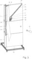
- Fig. 3
- eine Ansicht analog zur
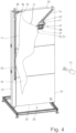
Fig. 2 in einer Zwischenstellung der Vorrichtung, bei der ein Sauger an einen textilen Gegenstand herangefahren ist, - Fig. 4
- eine Ansicht analog zu den
Fig. 2 und3 in einer weiteren Zwischenstellung der Vorrichtung, bei der der textile Gegenstand von einem Greifer erfasst ist, - Fig. 5
- eine Darstellung der Vorrichtung analog zu den
Fig. 2 bis 4 in einer Übernahmestellung, - Fig. 6
- eine Draufsicht auf die Vorrichtung der
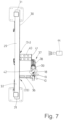
Fig. 2 , - Fig. 7
- eine Draufsicht auf die Vorrichtung der
Fig. 3 , - Fig. 8
- eine Draufsicht auf die Vorrichtung der
Fig. 4 bei noch geöffneter Klammer, und - Fig. 9
- eine Draufsicht auf die Vorrichtung gemäß der
Fig. 5 .
- Fig. 1
- a schematic view of the device with upstream and downstream devices,
- Fig. 2
- a perspective view of only the device for automatically gripping rectangular textile objects in a starting position,
- Fig. 3
- a view analogous to
Fig. 2 in an intermediate position of the device in which a vacuum cleaner has moved up to a textile object, - Fig. 4
- a view analogous to the
Fig. 2 and3 in a further intermediate position of the device, in which the textile object is gripped by a gripper, - Fig. 5
- a representation of the device analogous to that
Fig. 2 to 4 in a takeover position, - Fig. 6
- a top view of the device
Fig. 2 , - Fig. 7
- a top view of the device
Fig. 3 , - Fig. 8
- a top view of the device
Fig. 4 with the bracket still open, and - Fig. 9
- a top view of the device according to
Fig. 5 .
Die in den Figuren gezeigte Vorrichtung und das damit durchführbare Verfahren dienen dazu, rechteckige textile Gegenstände automatisch zu ergreifen und vorzugsweise solche textilen Gegenstände auch automatisch einer Behandlungseinrichtung zuzuführen.The device shown in the figures and the method that can be carried out with it serve to automatically grip rectangular textile objects and preferably also to automatically feed such textile objects to a treatment device.
In der folgenden Beschreibung wird davon ausgegangen, dass es sich bei den textilen Gegenständen um gewaschene und/oder noch zu waschende rechteckige Wäschestücke 10 handelt. Bevorzugt betreffen die Wäschestücke 10 sogenannte Flachwäschestücke, wie z. B. Tischdecken, Servietten, Bettlaken, Bettbezüge und/oder Kopfkissenbezüge. Die rechteckigen Wäschestücke 10 weisen üblicherweise ungleich lange Ränder auf, indem zwei parallele Ränder größer sind als zwei quer dazu verlaufende parallele Ränder. Die Wäschestück 10 können aber auch quadratisch sein mit vier gleich langen Rändern. In den Figuren sind die vertikalen Ränder die längeren Ränder. Sie werden als Längsränder 11 bezeichnet, während die horizontalen Ränder die als Querränder 12 bezeichneten kürzeren Ränder sind.In the following description it is assumed that the textile objects are washed and/or yet to be washed rectangular items of
Die Bereitstellungseinrichtung 17 führt gegebenenfalls eine endgültige Vereinzelung mehrerer gleichzeitig vom Greifer 16 ergriffener Wäschestücke 10 durch und hält das vereinzelte (nunmehr einzige) Wäschestück 10 zur Übernahme einer ersten Ecke 18 bereit. Diese Übernahme erfolgt durch eine Klammer 19 der in Transportrichtung 20, nämlich Wäscheflussrichtung und/oder Zuführrichtung, folgenden Vorrichtung der Erfindung. Die Klammer 19 kann alternativ auch einen Eckbereich der Ecke 18 ergreifen. Auch wenn in der Beschreibung nur die Ecke 18 erwähnt ist, soll das auch einen Eckbereich um die Ecke 18 beinhalten.The
In Transportrichtung 20 folgt hinter der Vorrichtung ein die Wäschestücke 10 weitertransportierender Förderer 21. Im gezeigten Ausführungsbeispiel ist der Förderer 21 aus einer Fördererkaskade 22 gebildet. Die Fördererkaskade 22 besteht aus mehreren in Transportrichtung 20 direkt aufeinanderfolgenden Paaren sandwichartig übereinander angeordneter Gurtförderer 23. Zwischen diesen übereinander angeordneten Gurtförderern 23, nämlich dem zueinander gerichteten Trum derselben, sind die Wäschestücke 10 in Transportrichtung 20 längs der Fördererkaskade 22 zu einer dieser nachfolgenden Eingabemaschine 24 transportierbar. Das anfängliche Paar übereinanderliegender Gurtförderer 23 der Fördererkaskade 22 ist unterschiedlich lang ausgebildet. Der untere Gurtförderer 23 ist länger als der darüber liegende obere Gurtförderer 23. Dadurch entsteht am Anfang der Fördererkaskade 22 auf dem anfänglichen Obertrum des unteren Gurtförderers 23 ein freiliegender Ablegebereich 25 für jeweils ein Wäschestück 10. Das jeweilige Wäschestück 10 wird je nach Orientierung in Transportrichtung 20 auf den Ablegebereich 25 aufgezogen oder quer über den Ablegebereich 25 herübergezogen, wonach das jeweilige Wäschestück 10 in einer umgekehrt U-förmigen Konfiguration auf dem Ablegebereich 25 am Anfang der Fördererkaskade 22 aufliegt. Diese U-förmige Konfiguration des auf den Ablegebereich 25 aufgelegten Wäschestücks 10 kommt dadurch zustande, dass die Gurtförderer 23 relativ schmal ausgebildet sind, nämlich eine Breite aufweisen, die je nach Größe des Wäschestücks 10 ein bis fünf Zehntel der Breite desselben entspricht. Dadurch hängen gegenüberliegende äußere Randbereiche des Wäschestücks 10 im Bereich des Ablegebereichs 25 von gegenüberliegenden Seiten des Gurtförderers 23 herunter zur Bildung idealerweise, aber nicht zwingend, gleich langer Schenkel des U-förmigen konfigurierten Wäschestücks 10. Ein zwischen den Schenkeln bzw. äußeren Randbereichen liegender, zentraler, vorzugsweise mittiger, Bereich des Wäschestücks 10, der die gegenüberliegenden Schenkel stegartig verbindet, liegt dabei auf dem Ablegebereich 25 auf.Following the device in the
In Transportrichtung 20 aufeinanderfolgende obere und untere Gurtförderer 23 der Fördererkaskade 22 werden mit voneinander abweichender und in Transportrichtung 20 gleich zunehmender Transportgeschwindigkeit angetrieben, wodurch beim Hindurchlaufen des jeweiligen Wäschestücks 10 durch die Fördererkaskade 22, also den Weitertransport des Wäschestücks 10 entlang des Förderers 21 in Transportrichtung 20, ein Ausstreifen des Wäschestücks 10 in Transportrichtung 20 erfolgt, so dass am Ende des Förderers 21, also dem letzten Gurtförderer 23 der Fördererkaskade 22, das jeweilige Wäschestück 10 in Transportrichtung 20 zumindest größtenteils ausgestreckt umgekehrt U-förmig über dem letzten unteren Gurtförderer 23 der Fördererkaskade 22 liegt.Upper and
Es ist auch ein alternatives Ausführungsbeispiel des Förderers 21 denkbar, bei dem dieser aus keiner Fördererkaskade 22 gebildet ist und/oder keine Gurtförderer 23 sandwichartig übereinander angeordnet sind. Im einfachsten Falle besteht der Förderer 21 dann aus einem einzigen durchgehenden Förderer, auf dem das jeweilige Wäschestück 10 aufgelegt oder aufgezogen wird, und zwar bevorzugt auch in einer umgekehrt U-förmigen Konfiguration. Gegebenenfalls können mehrere kürzere untere Gurtförderer aufeinanderfolgen. Diese können auch verschiedene Transportgeschwindigkeiten aufweisen, vorzugsweise solche, die in Transportrichtung 20 gesehen zunehmen.An alternative embodiment of the conveyor 21 is also conceivable, in which it is not formed from a conveyor cascade 22 and/or no
In Transportrichtung 20 folgt auf den Förderer 21 die Eingabemaschine 24. Die gezeigte Eingabemaschine 24 verfügt über eine Beladestation, die im gezeigten Ausführungsbeispiel über einen Beladeförderer 27, der die Fördererkaskade 22 des Förderers 21 in Transportrichtung 20 verlängert und auch über zwei übereinanderliegend sandwichartig angeordnete Gurtförderer 28 verfügt. Die Gurtförderer 28 weisen eine Breite auf, die derjenigen der Gurtförderer 23 entspricht, sind also auch verhältnismäßig schmal.In the
Bei Eingabemaschinen 24 mit mehreren Beladestationen mit zum Beispiel Beladeförderern 27 sind zumindest für jede Beladestation eine erfindungsgemäße Vorrichtung und/oder ein darauffolgender Förderer 21 zugeordnet. Bei einer Eingabemaschine 24 mit drei nebeneinanderliegenden, vorzugsweise gleichen Beladestationen sind dann vor der Eingabemaschine 24 drei Vorrichtungen und drei Förderer 21 vorgesehen, so dass jede Vorrichtung und jeder Förderer zum Beschicken, nämlich Zuführen, von Wäschestücken 10 zu einer Beladestation der Eingabemaschine 24 dient.In the case of
Es ist alternativ auch denkbar, den textilen Gegenstand von der Vorrichtung direkt an eine Behandlungseinrichtung, beispielsweise die Eingabemaschine 24, vorzugweise einen Beladeförderer 27 derselben, zu übergeben.Alternatively, it is also conceivable to transfer the textile object from the device directly to a treatment device, for example the
Die Vorrichtung verfügt über eine im gezeigten Ausführungsbeispiel senkrechte Wand 29. Gegebenenfalls kann die Wand 29 auch aufrecht mit leichter Schrägstellung ihrer Vorderseite 30 verlaufen. Die rechteckige Wand 29 ist vorzugsweise ortsfest zwischen der Bereitstellungseinrichtung 17 des Vereinzelers 13 und dem Förderer 21 angeordnet. Gegebenenfalls kann die Wand 29 auch verfahrbar sein. Die aufrecht stehende Wand 29 verfügt über eine rechteckige Grundfläche mit aufrechten, längeren Längskanten 31 und kürzeren, horizontalen Querkanten 32. Die Grundfläche der Vorderseite 30 der Wand 29 ist so bemessen, dass vor ihr die größten zu verarbeitenden Wäschestücke 10 hängen können.The device has a
Der Wand 29 sind eine mit geringem Abstand parallel zur in Bezug auf die Figuren linken Längskante 31 verlaufende senkrechte, geradlinige Schiene 33 und eine schräge, geradlinige Schiene 34 zugeordnet. Die Schienen 33 und 34 sind im hier gezeigten Ausführungsbeispiel in die Wand 29 eingelassen, aber zur Vorderseite 30 der Wand 29 offen bzw. freiliegend. Denkbar ist es aber auch, die Schienen 33 und 34 auf der Vorderseite 30 der Wand 29 zu befestigen. Die schräg verlaufende Schiene 34 verfügt über ein neben der senkrechten Schiene 33 liegendes unteres Ende und ein höher liegendes gegenüberliegendes Ende. Das untere Ende der schräg gerichteten geradlinigen Schiene 34 befindet sich etwa auf halber Höhe der vertikalen Schiene 33, vorzugsweise etwas darunter. Das höherliegende gegenüberliegende Ende der schräggerichteten Schiene 34 befindet sich in einem oberen rechten Eckbereich der Vorderseite 30 der Wand 29. Es handelt sich hierbei um diejenige Seite der Wand 29, die der senkrechten Schiene 33 gegenüberliegt.The
Auf der senkrechten Schiene 33 ist die bereits erwähnte Klammer 19 an einem Klammerlaufwagen 36 auf und ab verfahrbar. Die Klammer 19 ist quer zur schrägen Schiene 34 weisend am Klammerlaufwagen 36 befestigt, und zwar so, dass das Klammermaul der Klammer 19 mit geringem Abstand vor der Vorderseite 30 der Wand 29 auf- und abbewegbar ist.On the
Längs der schräggerichteten Schiene 34 ist ein Haltemittel 37 in entgegengesetzten Richtungen verfahrbar. Das Haltemittel 37 verfügt über zwei unabhängig arbeitende Haltemittel für das Wäschestück 10, und zwar einen pneumatisch mit Unterdruck arbeitenden Sauger 38 und einen mechanischen Greifer 39. Der Sauger 38 und der Greifer 39 sind gemeinsam an einem längs der Schiene 34 verfahrbaren Laufwagen 40 befestigt. Diese Befestigung geschieht derart, dass die Saugrichtung des Saugers 38 und das Maul des Greifers 39 parallel zur Wand 29 verlaufen, und zwar mit geringem Abstand vor der Vorderseite 30 der Wand 29. Dabei sind sowohl der Sauger 38 als auch der Greifer 39 derart parallel zueinander orientiert, dass die Saugrichtung des Saugers 38 und das Maul des Greifers 39 parallel zu den Querkanten 32 der Wand 29 bzw. der Vorderseite 30 desselben verlaufen. Es ist denkbar, den Sauger 38 und/oder den Greifer 39 auf einer gemeinsamen Tragplatte 41 zu befestigen, die um eine senkrecht zur Ebene der Vorderseite 30 der Wand 29 verlaufende Drehachse frei und/oder gezielt angetrieben drehbar ist zur Anpassung an die Orientierung des vom Sauger 38 und Greifer 39 zu erfassenden Bereichs des Wäschestücks 10, insbesondere dicht nebeneinanderliegenden Stellen 42 und 43 des Wäschestücks.A holding means 37 can be moved in opposite directions along the
Der Vorrichtung ist mindestens eine bildgebende Einrichtung zugeordnet. Diese Zuordnung ist derart getroffen, dass die bildgebende Einrichtung auf die Vorderseite 30 der Wand 29 gerichtet ist, um so ein Bild von mindestens einem die gewünschten Informationen liefernden Teil des vor der Wand 29 herunterhängenden Wäschestücks 10 zu liefern. Vorzugsweise dient die mindestens eine bildgebende Einrichtung dazu, das ganze Wäschestück 10 oder mindestens einen Großteil desselben vor der Wand 29 zu erfassen und davon wenigstens ein Bild zu erzeugen. Bei der bildgebenden Einrichtung handelt es sich bevorzugt um einen Kamera 44. Die Kamera 44 kann als Schwarz-Weiß-Kamera oder als Farbkamera ausgebildet sein, die zwei- oder dreidimensionale Bilder erzeugt.At least one imaging device is assigned to the device. This assignment is made in such a way that the imaging device is directed at the
Es ist auch denkbar, an wenigstens einer anderen Stelle vor oder neben der Wand 29 mindestens eine weitere bildgebende Einrichtung vorzusehen, die auch als Kamera ausgebildet sein kann. Eine solche bildgebende Einrichtung kann mindestens ein Bild aus einer anderen Blickrichtung des vor der Wand 29 herunterhängenden Wäschestücks 10 oder gewünschte Details derselben zusätzlich aufnehmen.It is also conceivable to provide at least one further imaging device, which can also be designed as a camera, at at least one other location in front of or next to the
Die Vorrichtung verfügt außerdem über eine Klammer 45 oder es ist eine solche Klammer 45 der Vorrichtung zugeordnet. Diese Klammer 45 ist ausgebildet, um einen Abschnitt des sich unter der Klammer 19 frei herunterhängenden Rand, wobei es sich um einen Längsrand 11 oder einen Querrand 12 handeln kann, zu ergreifen. Ergriffen wird im gezeigten Ausführungsbeispiel von der Klammer 45 ein Abschnitt 46 des von der Klammer 19 frei herunterhängenden linken Längsrands 11 des Wäschestücks 10. Dieser Abschnitt 46 liegt zwischen zwei von benachbarten Ecken des frei herunterhängenden Längsrands 11 ausgehenden Endabschnitten 47 und 48.The device also has a
Damit die Klammer 45 den innenliegenden bzw. etwa mittigen Abschnitt 46 des von der Klammer 19 frei herunterhängenden Rands des Wäschestücks 10 ergreifen kann, ist sie bei der gezeigten Vorrichtung als Doppelklammer mit zwei beabstandeten Einzelklammern 49 ausgebildet. Der Abstand der Einzelklammern 49 entspricht der Länge des von der Klammer 45 zu erfassenden Abschnitts 46 des senkrecht herunterhängenden Rands des Wäschestücks 10. Alternativ ist es aber auch denkbar, die Klammer 45 als eine längliche Klammer auszubilden, deren Klammermaul so lang ist, dass es sich über den gesamten Abschnitt 46 des zu ergreifenden senkrecht herunterhängenden Rands, hier des Längsrands 11, des Wäschestücks 10 erstreckt.So that the
Die Klammer 45 ist am Ende eines Arms einer Handhabungseinrichtung angeordnet. Die Handhabungseinrichtung ist so ausgebildet, dass von ihr, insbesondere ihrem Arm, die Klammer 46 im dreidimensionalen Raum mindestens dreiachsig bewegbar ist. Außerdem kann es vorgesehen sein, dass die Klammer 45 am Ende des Arms der Handhabungseinrichtung gezielt verdrehbar und/oder verschwenkbar angeordnet ist. Die Handhabungseinrichtung überführt das jeweilige Wäschestück 10 von der Stelle, an der es vor der Wand 29 von der Klammer 45 ergriffen wird, zum Ablegebereich 25 des Förderers 21 vor der Eingabemaschine 24The
Im gezeigten Ausführungsbeispiel ist die Handhabungseinrichtung als ein Roboter 50 ausgebildet. Alternativ kann die Handhabungseinrichtung auch kranartig ausgebildet sein.In the exemplary embodiment shown, the handling device is designed as a
Die Bewegungen der Handhabungseinrichtung, insbesondere des Roboters 50, werden gesteuert anhand der von der mindestens einen bildgebenden Einrichtung, insbesondere Kamera 44, aufgenommenen Bilddaten. Auch können die Bewegungen des Saugers 38 und/oder des Greifers 39 anhand der von der Kamera 44 oder einer anderen bildgebenden Einrichtung gelieferten Bilddaten gesteuert werden. Das gilt auch für den Zeitpunkt des Ergreifens des Wäschestücks 10 vom Greifer 39 und Deaktivieren des Saugers 38 und/oder des Verfahrens des Haltemittels 37 längs der schrägen Schiene 34.The movements of the handling device, in particular the
Nachfolgend wird ein bevorzugtes Ausführungsbeispiel des Verfahrens mit der zuvor beschriebenen Vorrichtung beschrieben. Hier wird davon ausgegangen, dass es sich beim Wäschestück 10 um ein solches Wäschestück handelt, das über im Vergleich zu den Längsrändern 11 kürzeren Querränder 12 verfügt, das Wäschestück 10 mit quer zur Transportrichtung 20 verlaufendem Querrand 12 auf den Auflegebereich 25 des Förderers 21 aufgezogen wird und das Wäschestück 10 von der Klammer 19 mit dem (längeren) Längsrand 11 herunterhängt.A preferred exemplary embodiment of the method with the previously described device is described below. It is assumed here that the item of
Ein vom Vereinzeler 13 vereinzeltes Wäschestück 10 wird von der Bereitstellungseinrichtung 17 des Vereinzelers 13 zur Übernahme durch die Klammer 19 der Vorrichtung bereitgehalten oder es wird das Wäschestück 10 von der Bereitstellungseinrichtung 17 an die Klammer 19 übergeben. Die Übernahme oder das Übergeben des Wäschestücks 10 an die Klammer 19 erfolgt so, dass die Klammer 19 der Vorrichtung das Wäschestück in einem Eckbereich, insbesondere einer ersten Ecke 18, hält. Bei der Übernahme oder Übergabe des Wäschestücks 10 an die Vorrichtung kann die Klammer 19 auf der geradlinigen senkrechten Schiene 33 eine Position einnehmen, die die Übergabe oder Übernahme der Ecke 18 des Wäschestücks 10 von der Klammer 19 zulässt bzw. begünstigt. Erforderlichenfalls wird die Klammer 19 nach der Übernahme der ersten Ecke 18 des Wäschestücks 10 längs der senkrechten geradlinigen Schiene 34 so weit hochgefahren, dass das Wäschestück 10 von der in der Klammer 19 gehaltenen ersten Ecke 18 frei herunterhängt. Bevorzugt ist es vorgesehen, die erste Klammer 19 zur Übernahme des Wäschestücks 10 bis zum oberen Ende der senkrechten Schiene 33 hochzufahren. Bei relativ kleinen Wäschestücken 10 ist es zweckmäßig, die Klammer auf der Schiene 33 nur so weit zu verfahren, dass das untere freie Ende der schrägen Schiene 34 sich im Zentrum des Wäschestücks 10 befindet, vorzugsweise etwa auf Höhe der halben Länge des von der Klammer 19 herunterhängenden Längsrands 11 des Wäschestücks 10.A piece of
Die auf das Wäschestück 10 vor der Wand 29 gerichtete Kamera 44 liefert Bilder, die zur Steuerung des Verfahrwegs der Klammer 19 und des Haltemittels 37 dienen können. Die Bilder bzw. Bilddaten von der Kamera 44 können aber alternativ oder zusätzlich auch dazu dienen, das Öffnen und Schließen der Klammer 19 und/oder des Saugers 38 und des Greifers 39 des Haltemittels 37 zu steuern. Insbesondere kann dadurch gesteuert werden, wann der Greifer 39 die Stelle 43 des Wäschestücks 10 ergreift und wann der Sauger 38 die von ihm erfasste Stelle 42 des Wäschestücks 10 loslässt.The
Es ist denkbar, den Sauger 38 und den Greifer 39 des Haltemittels 37 anhand von Bilddaten zu steuern, die von einer separaten Kamera in der Nähe des Haltemittels 37 oder sogar im Laufwagen 40 des Haltemittels 37 aufgenommen werden.It is conceivable to control the
Die wenigstens von der auf das Wäschestück 10 und die Wand 29 gerichteten Kamera 44 aufgenommenen Bilder des Wäschestücks 10, insbesondere Bilddaten der Bilder, werden vorzugsweise auch dazu verwendet, um festzustellen, ob es sich bei dem von der Klammer 19 herunterhängenden Rand des Wäschestücks 10 um einen Längsrand 11 (so wie in der vorstehenden und nachfolgenden Beschreibung angenommen) handelt oder um einen Querrand 12. Es müssen zur Ermittlung des Längsrands 11 und des Querrands 12 nicht exakt die Längenmaße derselben ermittelt werden. Es reicht, eine qualitative Vermessung vorzunehmen, die es ermöglicht, zwischen Längsrand 11 und Querrand 12 zu unterscheiden bzw. festzustellen, ob beide Ränder bei quadratischen Wäschestücken 10 gleich lang sind. Es ist dabei denkbar, die Vorderseite 30 der Wand 29 mit einem Raster, insbesondere schachbrettartigen Raster, zu versehen, wodurch sich die Längenmaße des Längsrands 11 und des Querrands 12 ermitteln lassen und gegebenenfalls daraus auch die Größe des jeweiligen Wäschestücks 10 rechnerisch ermittelbar ist.The images of the item of
Auch der Roboter 50 oder eine vergleichbare Handhabungseinrichtung zum Bewegen der Klammer 45 wird mindestens zum Ergreifen des innenliegenden, vorzugsweise mittigen, Abschnitts 46 des von der Klammer 19 herunterhängenden Längsrands 11 anhand der von der Kamera 44 aufgenommenen Bilder und/oder ihrer Bilddaten gesteuert. Ebenso sind das Öffnen und Schließen der Klammer 45 steuerbar. Mit den von der Kamera 44 aufgenommenen Bildern bzw. Bilddaten wird die Steuerung des Roboters 50 und der Klammer 45 versorgt. Der Roboter 50 fährt dann die Klammer 45 an den innenliegenden bzw. mittigen Abschnitt 46 des senkrecht herunterhängenden Längsrands 11 des Wäschestücks 10 heran. Nach dem anschließenden Ergreifen des Abschnitts 46 von der Klammer 45, insbesondere ihren beabstandeten Einzelklammern 49, wird die erste Ecke 18 durch Öffnen der Klammer 19 losgelassen und ebenso vorzugsweise die gegenüberliegende zweite Ecke 52 vom Greifer 39 des Haltemittels 37 gelöst. Das Wäschestück 10 hängt danach an der als Doppelklammer oder breiten Klammer ausgebildeten Klammer 45 herunter, wobei der zentrale Abschnitt 46 des Längsrands 11 gestreckt zwischen den Einzelklammern 49 der Klammer 45 oder einer breiten Klammer gehalten ist.The
Anschließend wird die Klammer 45 mit dem daran hängenden Wäschestück 10 vom Roboter 50 oder einer sonstigen Handhabungseinrichtung zum Förderer 21 vor der Eingabemaschine 24 überführt.The
Weil im gezeigten Ausführungsbeispiel die Klammer 45 einen zentralen, insbesondere mittigen Abschnitts 46 des Längsrands 11 des Wäschestücks 10 hält, wird beim hier angenommenen Zuführen des Wäschestücks 10 mit quer zur Transportrichtung 20 verlaufendem Querrand 12 das Wäschestück 10 vom Roboter 50 quer zur Transportrichtung 20 über den Ablegebereich 25 des Förderers 21 gezogen, und zwar auf das hier freiliegende Obertrum des unteren vorderen Gurtförderers 28 desselben. Zu diesem Zweck ist die Klammer 45 so breit ausgebildet, dass der von ihr gehaltene Abschnitt 46 etwas größer ist als die Breite des Gurtförderers 28 im Ablegebereich 25.Because in the exemplary embodiment shown, the
Hat die Klammer 45 einen innenliegenden Abschnitt eines Querrands 12 des Wäschestücks 10 ergriffen, würde der Roboter 50 die Klammer 45 so bewegen, dass das Wäschestück 10 in Transportrichtung 20 auf den Ablegebereich 25 des Förderers 21 aufgezogen wird, wobei sich die Klammer 45 mit dem von ihr gehaltenen Abschnitt 46 des Querrands 12 des Wäschestücks 10 mittig in Transportrichtung 20 über den Ablegebereich 25 bewegt.If the
Umgekehrt zur vorstehend beschriebenen Vorgehensweise wird vorgegangen, wenn das Wäschestück 10 mit quer zur Transportrichtung 20 verlaufendem Längsrand 11 der Eingabemaschine 24 zugeführt werden soll. Dann wird beim von der Klammer 45 ergriffenen Längsrand 11 das Wäschestück 10 in Transportrichtung 20 auf den Ablegebereich 25 aufgezogen und beim von der Klammer 45 ergriffenen Querrand 12 das Wäschestück 10 quer zur Transportrichtung 20 über den Ablegebereich 25 gezogen.The reverse of the procedure described above is followed if the item of
Durch das zuvor beschriebene Aufziehen und Herüberziehen des Wäschestücks 10 auf oder über den Ablegebereich 25 des Förderers 21 hängt aufgrund der relativ schmalen Gurtförderer 28 zur Bildung des Förderers 21 das Wäschestück 10 in einer umgekehrt U-förmigen Konfiguration im Ablegebereich 25 über dem vorderen, unteren Gurtförderer 28. Hierbei erstreckt sich mindestens der ursprünglich von der Klammer 19 gehaltene innere, vorzugsweise mittlere, Abschnitt 46 des Wäschestücks 10 über den Ablegebereich 25 des Beladeförderers 27, während an den Abschnitt 46 beidseitig anschließende Randabschnitte des Wäschestücks 10 auf beiden Seiten vom Ablegebereich 25 des Förderers 21 herunterhängen.By lifting and pulling the item of
Nachdem das jeweilige Wäschestück 10 in vorstehend beschriebener Weise auf den Ablegebereich 25 des Förderer 21 aufgezogen worden ist, wird das Wäschestück 10 von dem Förderer 21, insbesondere seinen Gurtförderern 28, in Transportrichtung 20 zur Eingabemaschine 24 transportiert und vorzugsweise dabei in Transportrichtung 20 ausgestreckt, so dass das mindestens in Transportrichtung 20 gesehen faltenfreie oder wenigstens nahezu faltenfreie Wäschestück 10 vom Förderer 21 an den jeweiligen Beladeförderer 27 der Eingabemaschine 24 übergebbar ist, und zwar in der nunmehr ausgestreckten, aber immer noch umgekehrten U-förmigen Konfiguration.After the respective item of
Alternativ ist es denkbar, von der Klammer 19 das Wäschestück 10 oder einen anderen textilen Gegenstand direkt an eine Behandlungsmaschine zu übergeben, beispielsweise an die Eingabemaschine 24. Das kann durch mit der Klammer 19 erfolgendes Aufziehen des jeweiligen textilen Gegenstands auf einen Beladeförderer 27 der Eingabemaschine 24 geschehen.
Claims (5)
- A method for feeding rectangular textile items to a treatment installation, wherein a respective singularized textile item is gripped at a portion (46) of a periphery, it being determined before or after gripping the portion (46) of the periphery of the textile item, in the case of a textile item having peripheries of unequal length, whether this is a portion of a short or a long periphery, and the respective singularized textile item is pulled onto or over a conveyor (21) of the treatment installation that transports the textile item to the treatment installation or onto or over a loading conveyor (27) of the treatment installation, characterized in that, as a function of the result of the determination of the short or long periphery, the textile item by way of the gripped portion (46) of its periphery is pulled onto the conveyor (21) or loading conveyor (27) in a targeted manner so as to be transverse or longitudinal on said conveyor.
- The method as claimed in claim 1, characterized in that it is determined with the aid of at least one image-generating installation whether the portion (46) of the gripped periphery of the textile item that is acquired by the clamp (45) is a long periphery or a short periphery.
- The method as claimed in claim 1 or 2, characterized in that when the textile item is to be pulled onto the conveyor (21) or the loading conveyor (27) by way of the short periphery running transversely to the transporting direction (20), and the periphery of the textile item that is gripped by the clamp (45) is a short periphery, the clamp (45) pulls the textile item onto the conveyor (21) or loading conveyor (27) so as to be longitudinal in the transporting direction (20), whereas, in the case of the portion (46) of the long periphery being held by the clamp (45), the textile item is pulled over the conveyor (21) or the loading conveyor (27) transversely to the transporting direction (20) of the latter.
- The method according to one of the preceding claims, characterized in that the portion (46) of the periphery of the textile article formed under a corner (18) is gripped by a clamp (45), in particular a double clamp or a clamp having a width corresponding to the length of the portion (46).
- The method as claimed in claim 4, characterized in that the textile item Is pulled by the clamp (45) onto or over the conveyor (21) or the loading conveyor (27) which transports the textile item to a following laundry treatment installation, in particular an infeed machine (24).
Priority Applications (1)
| Application Number | Priority Date | Filing Date | Title |
|---|---|---|---|
| EP23167510.9A EP4219825A1 (en) | 2019-11-28 | 2020-11-27 | Method and device for gripping rectangular textile articles |
Applications Claiming Priority (2)
| Application Number | Priority Date | Filing Date | Title |
|---|---|---|---|
| DE102019132377 | 2019-11-28 | ||
| DE102019135659.8A DE102019135659A1 (en) | 2019-11-28 | 2019-12-23 | Method and device for gripping rectangular textile objects and / or for feeding rectangular textile objects to a treatment device |
Related Child Applications (2)
| Application Number | Title | Priority Date | Filing Date |
|---|---|---|---|
| EP23167510.9A Division EP4219825A1 (en) | 2019-11-28 | 2020-11-27 | Method and device for gripping rectangular textile articles |
| EP23167510.9A Division-Into EP4219825A1 (en) | 2019-11-28 | 2020-11-27 | Method and device for gripping rectangular textile articles |
Publications (3)
| Publication Number | Publication Date |
|---|---|
| EP3828332A2 EP3828332A2 (en) | 2021-06-02 |
| EP3828332A3 EP3828332A3 (en) | 2021-09-08 |
| EP3828332B1 true EP3828332B1 (en) | 2023-11-08 |
Family
ID=73642665
Family Applications (2)
| Application Number | Title | Priority Date | Filing Date |
|---|---|---|---|
| EP23167510.9A Pending EP4219825A1 (en) | 2019-11-28 | 2020-11-27 | Method and device for gripping rectangular textile articles |
| EP20210309.9A Active EP3828332B1 (en) | 2019-11-28 | 2020-11-27 | Method for feeding rectangular textile items to a treatment installation |
Family Applications Before (1)
| Application Number | Title | Priority Date | Filing Date |
|---|---|---|---|
| EP23167510.9A Pending EP4219825A1 (en) | 2019-11-28 | 2020-11-27 | Method and device for gripping rectangular textile articles |
Country Status (2)
| Country | Link |
|---|---|
| EP (2) | EP4219825A1 (en) |
| DK (1) | DK3828332T3 (en) |
Family Cites Families (8)
| Publication number | Priority date | Publication date | Assignee | Title |
|---|---|---|---|---|
| EP0372320B1 (en) * | 1988-12-02 | 1996-02-28 | Mitsubishi Jukogyo Kabushiki Kaisha | Method and apparatus for spreading sheets |
| DE3912977C2 (en) * | 1989-04-20 | 2001-04-19 | Kannegiesser H Gmbh Co | Method and device for feeding laundry to a mangle |
| EP0751251B1 (en) * | 1995-01-10 | 2002-05-15 | Tokai Co., Ltd. | Method of and apparatus for fully automatically finishing laundry of square cloth |
| EP1690976A1 (en) * | 2005-02-15 | 2006-08-16 | Jensen AG Burgdorf | Method of alignement of a laundry piece and apparatus for carrying out the same |
| DE102014005355A1 (en) * | 2014-04-11 | 2015-10-15 | Herbert Kannegiesser Gmbh | Method for detecting a laundry article |
| DE102014017477A1 (en) * | 2014-11-26 | 2016-06-02 | Herbert Kannegiesser Gmbh | Method and device for feeding items of laundry to a defect or other laundry treatment device |
| JP2016106659A (en) * | 2014-12-02 | 2016-06-20 | 株式会社プレックス | Washed square cloths conveyance device |
| DE102017005954A1 (en) * | 2017-06-26 | 2018-12-27 | Herbert Kannegiesser Gmbh | Method and device for feeding items of laundry to a laundry treatment device, in particular at least one loading conveyor |
-
2020
- 2020-11-27 EP EP23167510.9A patent/EP4219825A1/en active Pending
- 2020-11-27 DK DK20210309.9T patent/DK3828332T3/en active
- 2020-11-27 EP EP20210309.9A patent/EP3828332B1/en active Active
Also Published As
| Publication number | Publication date |
|---|---|
| EP4219825A1 (en) | 2023-08-02 |
| EP3828332A2 (en) | 2021-06-02 |
| EP3828332A3 (en) | 2021-09-08 |
| DK3828332T3 (en) | 2024-01-22 |
Similar Documents
| Publication | Publication Date | Title |
|---|---|---|
| EP3029195B1 (en) | Method and device for feeding laundry items to a mangle or another laundry treatment device | |
| EP3421659B1 (en) | Method and device for feeding laundry items into a laundry treatment device, in particular at least one conveyor | |
| DE102014017478A1 (en) | Method for sorting laundry items, in particular laundry items | |
| EP2930264A1 (en) | Method for detecting an item of laundry | |
| DE102016012274A1 (en) | Method for feeding items of laundry to a laundry treatment device and device | |
| EP3147405A1 (en) | Method and device for spreading a laundry item | |
| DE102009058637A1 (en) | Method and apparatus for feeding a garment to a defect or the like | |
| EP3636825B1 (en) | Method and device for supplying laundry items to a laundry treatment device, in particular a mangle | |
| EP3828332B1 (en) | Method for feeding rectangular textile items to a treatment installation | |
| DE4330911A1 (en) | Method and apparatus for feeding laundry articles to a treatment appliance | |
| EP3301218A2 (en) | Method and device for feeding laundry items into a laundry treatment device, in particular a mangle | |
| DE102019135659A1 (en) | Method and device for gripping rectangular textile objects and / or for feeding rectangular textile objects to a treatment device | |
| EP3680384B1 (en) | Method for determining the shorter and/or longer edge of pieces of laundry and for feeding pieces of laundry into a laundry treatment device | |
| EP3885484B1 (en) | Method for gripping textile objects | |
| DE102018122927B4 (en) | robotic system | |
| DE10349018A1 (en) | Method and device for feeding items of laundry to a laundry treatment device | |
| EP3656912B1 (en) | Method and devices for feeding laundry items to an insertion machine | |
| DE102019005696A1 (en) | Method and device for feeding items of laundry to a mangle or the like | |
| EP3575483B1 (en) | Method and device for loading a clip with a garment, in particular a garment to be sorted | |
| EP2918502B1 (en) | Device for packaging a stack of goods | |
| EP3751045A1 (en) | Method and device for feeding laundry items into a mangle or similar | |
| EP4067563A2 (en) | Method and devices for feeding laundry items into a laundry treatment device, in particular a mangle | |
| WO2022084409A1 (en) | Positioning apparatus and method for positioning a flexible, flat workpiece | |
| EP3656911A1 (en) | Device for feeding laundry items to feeding machine | |
| DD284709A5 (en) | DEVICE FOR THE AUTOMATIC TRANSFER OF TIGHTENING TREATMENTS FROM A TIGHTENING TREATMENT MACHINE TO A STORAGE DEVICE FOR STACKED TIGHTENING TREATMENTS |
Legal Events
| Date | Code | Title | Description |
|---|---|---|---|
| PUAI | Public reference made under article 153(3) epc to a published international application that has entered the european phase |
Free format text: ORIGINAL CODE: 0009012 |
|
| STAA | Information on the status of an ep patent application or granted ep patent |
Free format text: STATUS: THE APPLICATION HAS BEEN PUBLISHED |
|
| AK | Designated contracting states |
Kind code of ref document: A2 Designated state(s): AL AT BE BG CH CY CZ DE DK EE ES FI FR GB GR HR HU IE IS IT LI LT LU LV MC MK MT NL NO PL PT RO RS SE SI SK SM TR |
|
| PUAL | Search report despatched |
Free format text: ORIGINAL CODE: 0009013 |
|
| AK | Designated contracting states |
Kind code of ref document: A3 Designated state(s): AL AT BE BG CH CY CZ DE DK EE ES FI FR GB GR HR HU IE IS IT LI LT LU LV MC MK MT NL NO PL PT RO RS SE SI SK SM TR |
|
| RIC1 | Information provided on ipc code assigned before grant |
Ipc: D06F 95/00 20060101ALN20210802BHEP Ipc: D06F 93/00 20060101ALN20210802BHEP Ipc: D06F 67/04 20060101AFI20210802BHEP |
|
| STAA | Information on the status of an ep patent application or granted ep patent |
Free format text: STATUS: REQUEST FOR EXAMINATION WAS MADE |
|
| 17P | Request for examination filed |
Effective date: 20220304 |
|
| RBV | Designated contracting states (corrected) |
Designated state(s): AL AT BE BG CH CY CZ DE DK EE ES FI FR GB GR HR HU IE IS IT LI LT LU LV MC MK MT NL NO PL PT RO RS SE SI SK SM TR |
|
| GRAP | Despatch of communication of intention to grant a patent |
Free format text: ORIGINAL CODE: EPIDOSNIGR1 |
|
| STAA | Information on the status of an ep patent application or granted ep patent |
Free format text: STATUS: GRANT OF PATENT IS INTENDED |
|
| INTG | Intention to grant announced |
Effective date: 20230522 |
|
| GRAS | Grant fee paid |
Free format text: ORIGINAL CODE: EPIDOSNIGR3 |
|
| GRAA | (expected) grant |
Free format text: ORIGINAL CODE: 0009210 |
|
| STAA | Information on the status of an ep patent application or granted ep patent |
Free format text: STATUS: THE PATENT HAS BEEN GRANTED |
|
| AK | Designated contracting states |
Kind code of ref document: B1 Designated state(s): AL AT BE BG CH CY CZ DE DK EE ES FI FR GB GR HR HU IE IS IT LI LT LU LV MC MK MT NL NO PL PT RO RS SE SI SK SM TR |
|
| REG | Reference to a national code |
Ref country code: GB Ref legal event code: FG4D Free format text: NOT ENGLISH |
|
| REG | Reference to a national code |
Ref country code: CH Ref legal event code: EP |
|
| REG | Reference to a national code |
Ref country code: DE Ref legal event code: R096 Ref document number: 502020005934 Country of ref document: DE |
|
| REG | Reference to a national code |
Ref country code: IE Ref legal event code: FG4D Free format text: LANGUAGE OF EP DOCUMENT: GERMAN |
|
| P01 | Opt-out of the competence of the unified patent court (upc) registered |
Effective date: 20231129 |
|
| REG | Reference to a national code |
Ref country code: DK Ref legal event code: T3 Effective date: 20240119 |
|
| PGFP | Annual fee paid to national office [announced via postgrant information from national office to epo] |
Ref country code: FR Payment date: 20231214 Year of fee payment: 4 |
|
| REG | Reference to a national code |
Ref country code: LT Ref legal event code: MG9D |
|
| REG | Reference to a national code |
Ref country code: NL Ref legal event code: MP Effective date: 20231108 |
|
| PG25 | Lapsed in a contracting state [announced via postgrant information from national office to epo] |
Ref country code: GR Free format text: LAPSE BECAUSE OF FAILURE TO SUBMIT A TRANSLATION OF THE DESCRIPTION OR TO PAY THE FEE WITHIN THE PRESCRIBED TIME-LIMIT Effective date: 20240209 |
|
| PG25 | Lapsed in a contracting state [announced via postgrant information from national office to epo] |
Ref country code: IS Free format text: LAPSE BECAUSE OF FAILURE TO SUBMIT A TRANSLATION OF THE DESCRIPTION OR TO PAY THE FEE WITHIN THE PRESCRIBED TIME-LIMIT Effective date: 20240308 |
|
| PG25 | Lapsed in a contracting state [announced via postgrant information from national office to epo] |
Ref country code: LT Free format text: LAPSE BECAUSE OF FAILURE TO SUBMIT A TRANSLATION OF THE DESCRIPTION OR TO PAY THE FEE WITHIN THE PRESCRIBED TIME-LIMIT Effective date: 20231108 |
|
| PG25 | Lapsed in a contracting state [announced via postgrant information from national office to epo] |
Ref country code: NL Free format text: LAPSE BECAUSE OF FAILURE TO SUBMIT A TRANSLATION OF THE DESCRIPTION OR TO PAY THE FEE WITHIN THE PRESCRIBED TIME-LIMIT Effective date: 20231108 |