EP3828115B1 - Système d'arrêt d'urgence pour ascenseur - Google Patents
Système d'arrêt d'urgence pour ascenseur Download PDFInfo
- Publication number
- EP3828115B1 EP3828115B1 EP20210484.0A EP20210484A EP3828115B1 EP 3828115 B1 EP3828115 B1 EP 3828115B1 EP 20210484 A EP20210484 A EP 20210484A EP 3828115 B1 EP3828115 B1 EP 3828115B1
- Authority
- EP
- European Patent Office
- Prior art keywords
- elevator
- circuit
- controller
- holding relay
- elevator car
- Prior art date
- Legal status (The legal status is an assumption and is not a legal conclusion. Google has not performed a legal analysis and makes no representation as to the accuracy of the status listed.)
- Active
Links
- 238000000034 method Methods 0.000 description 24
- 230000033001 locomotion Effects 0.000 description 9
- 238000004590 computer program Methods 0.000 description 5
- 238000012423 maintenance Methods 0.000 description 5
- 238000004891 communication Methods 0.000 description 3
- 230000007246 mechanism Effects 0.000 description 3
- 229910000831 Steel Inorganic materials 0.000 description 2
- 230000005540 biological transmission Effects 0.000 description 2
- 239000010959 steel Substances 0.000 description 2
- 235000001674 Agaricus brunnescens Nutrition 0.000 description 1
- 230000001133 acceleration Effects 0.000 description 1
- 230000004075 alteration Effects 0.000 description 1
- 238000009429 electrical wiring Methods 0.000 description 1
- 230000005670 electromagnetic radiation Effects 0.000 description 1
- 239000000835 fiber Substances 0.000 description 1
- 238000007689 inspection Methods 0.000 description 1
- 238000009434 installation Methods 0.000 description 1
- 238000012806 monitoring device Methods 0.000 description 1
- 238000012544 monitoring process Methods 0.000 description 1
- 238000006467 substitution reaction Methods 0.000 description 1
Images
Classifications
-
- B—PERFORMING OPERATIONS; TRANSPORTING
- B66—HOISTING; LIFTING; HAULING
- B66B—ELEVATORS; ESCALATORS OR MOVING WALKWAYS
- B66B5/00—Applications of checking, fault-correcting, or safety devices in elevators
- B66B5/0043—Devices enhancing safety during maintenance
- B66B5/005—Safety of maintenance personnel
- B66B5/0056—Safety of maintenance personnel by preventing crushing
-
- B—PERFORMING OPERATIONS; TRANSPORTING
- B66—HOISTING; LIFTING; HAULING
- B66B—ELEVATORS; ESCALATORS OR MOVING WALKWAYS
- B66B1/00—Control systems of elevators in general
- B66B1/24—Control systems with regulation, i.e. with retroactive action, for influencing travelling speed, acceleration, or deceleration
- B66B1/28—Control systems with regulation, i.e. with retroactive action, for influencing travelling speed, acceleration, or deceleration electrical
-
- B—PERFORMING OPERATIONS; TRANSPORTING
- B66—HOISTING; LIFTING; HAULING
- B66B—ELEVATORS; ESCALATORS OR MOVING WALKWAYS
- B66B1/00—Control systems of elevators in general
- B66B1/34—Details, e.g. call counting devices, data transmission from car to control system, devices giving information to the control system
- B66B1/3415—Control system configuration and the data transmission or communication within the control system
- B66B1/3446—Data transmission or communication within the control system
- B66B1/3461—Data transmission or communication within the control system between the elevator control system and remote or mobile stations
-
- B—PERFORMING OPERATIONS; TRANSPORTING
- B66—HOISTING; LIFTING; HAULING
- B66B—ELEVATORS; ESCALATORS OR MOVING WALKWAYS
- B66B5/00—Applications of checking, fault-correcting, or safety devices in elevators
- B66B5/02—Applications of checking, fault-correcting, or safety devices in elevators responsive to abnormal operating conditions
- B66B5/021—Applications of checking, fault-correcting, or safety devices in elevators responsive to abnormal operating conditions the abnormal operating conditions being independent of the system
- B66B5/025—Applications of checking, fault-correcting, or safety devices in elevators responsive to abnormal operating conditions the abnormal operating conditions being independent of the system where the abnormal operating condition is caused by human behaviour or misbehaviour, e.g. forcing the doors
-
- H—ELECTRICITY
- H04—ELECTRIC COMMUNICATION TECHNIQUE
- H04W—WIRELESS COMMUNICATION NETWORKS
- H04W4/00—Services specially adapted for wireless communication networks; Facilities therefor
- H04W4/02—Services making use of location information
- H04W4/029—Location-based management or tracking services
Definitions
- the embodiments herein relate to elevator systems and more specifically to a system and method for an emergency stop system for an elevator.
- an elevator pit i.e., in an elevator hoistway
- a person such as a field technician needs access. This circumstance may pose a risk to such persons if an elevator car is allowed to run in the hoistway.
- JP H02 169482 A describes am elevator control apparatus where the elevator car is forcibly stopped at a predetermined position in the hoistway, when a person engaged in maintenance and inspection of the elevator carries a transmitting means.
- US 2002/0117358 A1 describes an elevator safety installation with a shaft monitoring device which takes the elevator out of service in a dangerous situation.
- JP 2015198609 A1 describes a maintenance operation device and system for an elevator where positional information about a maintenance person is acquired via a maintenance operation device and sent to the elevator controller, if the positional information indicated the person is in an off-limits region the controller stops the elevator from traveling.
- an elevator system is provided in accordance with claim 1.
- the first architectural location is in or near a hoistway pit.
- the holding relay is further configured to: energize the circuit responsive to receiving a second signal from the mobile device when the mobile device has left the first architectural location.
- the elevator system includes: an elevator controller operationally connected to the circuit and configured to: stop an elevator car or prevent the elevator car from traveling to the first architectural location upon detecting that the circuit is deenergized; and run the elevator car upon detecting that the circuit is energized.
- the elevator system includes: a hoistway, wherein: the elevator controller is in a controller room of the hoistway; the first architectural location is a hoistway pit of the hoistway; and the elevator car is positioned to move within the hoistway.
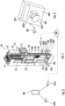
- FIG. 1 is a perspective view of an elevator system 101 including an elevator car 103, a counterweight 105, a tension member 107, a guide rail 109, a machine 111, a position reference system 113, and an elevator controller 115.
- the elevator car 103 and counterweight 105 are connected to each other by the tension member 107.
- the tension member 107 may include or be configured as, for example, ropes, steel cables, and/or coated-steel belts.
- the counterweight 105 is configured to balance a load of the elevator car 103 and is configured to facilitate movement of the elevator car 103 concurrently and in an opposite direction with respect to the counterweight 105 within an elevator shaft 117 (or hoistway) and along the guide rail 109.
- the tension member 107 engages the machine 111, which is part of an overhead structure of the elevator system 101.
- the machine 111 is configured to control movement between the elevator car 103 and the counterweight 105.
- the position reference system 113 may be mounted on a fixed part at the top of the elevator shaft 117, such as on a support or guide rail, and may be configured to provide position signals related to a position of the elevator car 103 within the elevator shaft 117. In other embodiments, the position reference system 113 may be directly mounted to a moving component of the machine 111, or may be located in other positions and/or configurations as known in the art.
- the position reference system 113 can be any device or mechanism for monitoring a position of an elevator car and/or counter weight, as known in the art.
- the position reference system 113 can be an encoder, sensor, or other system and can include velocity sensing, absolute position sensing, etc., as will be appreciated by those of skill in the art.
- the elevator controller 115 is located, as shown, in a controller room 121 of the elevator shaft 117 and is configured to control the operation of the elevator system 101, and particularly the elevator car 103.
- the elevator controller 115 may provide drive signals to the machine 111 to control the acceleration, deceleration, leveling, stopping, etc. of the elevator car 103.
- the elevator controller 115 may also be configured to receive position signals from the position reference system 113 or any other desired position reference device.
- the elevator car 103 may stop at one or more landings 125 as controlled by the elevator controller 115.
- the elevator controller 115 can be located and/or configured in other locations or positions within the elevator system 101. In one embodiment, the controller may be located remotely or in the cloud.
- the machine 111 may include a motor or similar driving mechanism.
- the machine 111 is configured to include an electrically driven motor.
- the power supply for the motor may be any power source, including a power grid, which, in combination with other components, is supplied to the motor.
- the machine 111 may include a traction sheave that imparts force to tension member 107 to move the elevator car 103 within elevator shaft 117.
- FIG. 1 is merely a non-limiting example presented for illustrative and explanatory purposes.
- a hoistway pit (pit) 200 (also referred to as a first architectural location) is illustrated.
- a person 210 such as a field technician may need to enter the hoistway pit (pit) 200, e.g., to perform maintenance.
- a stop switch 220 may be positioned within the pit 200.
- the stop switch 220 is electronically connected with the elevator controller 115 in the controller room 121 by a circuit 230 (shown schematically) having a holding relay 2310 which keeps the circuit 230 energized.
- the circuit 230 may be wired through the elevator shaft 117, e.g., along the guide rail 109.
- the stop switch 220 may include a housing 2205.
- a pull cap 2210 may extend forwardly from the housing 2205.
- the pull cap 2210 may be, e.g. a mushroom style pull cap (plunger).
- the stop switch 220 is in a stop configuration. This may disrupt power to the holding relay 2310, which may deenergize the circuit 230.
- the elevator controller 115 may stop the elevator car 103.
- the pull cap 2210 is retracted, i.e., pushed back toward the housing 2205, the stop switch 220 is in a run configuration, or vice versa.
- the holding relay 2310 may be energized, which may energize the circuit 230.
- the elevator controller 115 may run the elevator car 103.
- the stop switch 220 may include a motion sensor 2215 that may be integrated into the housing 2205.
- a switch controller 2220 of the stop switch 220 may be in electronic communication with the motion sensor 2215.
- the stop switch 220 may send a first signal to the holding relay 2310, via a holding relay controller 2325, to deenergize the circuit 230. As indicated above, this may result in the elevator controller 115 sensing the power loss in the circuit 230 and stopping the elevator car 103.
- the stop switch 220 may send a second signal to the holding relay 2310 to energize the circuit 230. As indicated above, this may result in the elevator controller 115 sensing the restored power in the circuit 230 and running the elevator car 103.
- FIG. 2 illustrates the housing 2205, the pull cap 2210 and the motion sensor 2215 of the stop switch 220.
- the stop switch 220 may further include an actuator 2225, illustrated schematically.
- the actuator 2225 may be a solenoid or other implement that is controlled, e.g., by the switch controller 2220.
- the actuator 2225 Upon the stop switch 220 sensing the person 210 in the pit 200, the actuator 2225 is controlled to push out the pull cap 2210. This action places the stop switch 220 in the stop configuration, or vice versa.
- the stop switch 220 when the stop switch 220 is in the stop configuration, power may be disrupted to the holding relay 2310, the circuit 230 may be deenergized, and the elevator controller 115 may stop the elevator car 103. Manually retracting (pushing back) the pull cap 2210 toward the housing 2205, the stop switch 220 is again in the run configuration. Upon entering the run configuration, the holding relay 2310 may be energized, which may energize the circuit 230. Upon sensing power in the circuit 230, the elevator controller 115 may run the elevator car 103.
- the person 210 has a mobile device (mobile phone) 240.
- the mobile phone 240 has a communication module 2410 and a geo-tracking module 2420, e.g., to track a specific location of the mobile phone 240.
- the mobile phone 240 and the holding relay 2310 are both configured to communicate over a wireless network 250, which may be a Bluetooth or other personal area network or similar low energy and rapid pairing network.
- the mobile phone 240 may transmit a third signal to the holding relay 2310.
- the third signal may be the same as the first signal, instructing the holding relay 2310 to deenergize the circuit 230. As indicated above, this may result in the elevator controller 115 sensing the power loss in the circuit 230 and stopping the elevator car 103.
- the signal is always transmitted by the mobile phone 240, e.g., so that the holding relay 2310 receives the signal whenever the mobile phone 240 is in close proximity to the pit 200.
- the communications may be calibrated so that the signal is received when the mobile phone 240 is in or near the pit 200.
- the mobile phone 240 may send a fourth signal to the holding relay 2310, or may send no additional signal.
- the fourth signal may be the same as the second signal, instructing the holding relay 2310 to energize the circuit 230.
- the holding relay 2310 may energize the circuit 230 after detecting no additional signal for a predetermined period of time. As indicated above, this may result in the elevator controller 115 sensing the restored power in the circuit 230 and running the elevator car 103.
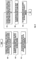
- FIG. 4 a flowchart shows a method of operating the elevator system 101 according to an embodiment.
- the method includes the mobile phone 240 transmitting the first signal to the holding relay 2310 to deenergize the circuit 230 upon the mobile phone 240 detecting via the geo-tracking module that it is in the pit 200, or when the mobile phone 240 is close enough to the holding relay 2310 such that the first signal is received.
- the method includes the holding relay 2310 deenergizing the circuit 230 responsive to receiving a first signal via the wireless network 250.
- the method includes the elevator controller 115 stopping an elevator car 103 upon detecting that the circuit 230 is deenergized.
- the elevator car 101 is controlled such that it remains a predefined distance of the pit 200, e.g., where the distance is measured in meters (feet) or levels.
- the method includes the mobile phone 240 transmitting the second signal to the holding relay 2310 to energize the circuit 230 upon the mobile phone 240 detecting that it has left the pit 200.
- the method includes the holding relay 2310 energizing the circuit 230 responsive to receiving the second signal.
- the method includes the elevator controller 115 running the elevator car 103 upon detecting that the circuit 230 is energized.
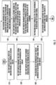
- FIG. 5 a further flowchart shows a non-claimed method of operating the elevator system 101 according to another embodiment.
- the method may include the stop switch 220 detecting, via the motion sensor 2215, that a person 210 (or another moving object) is located in the pit 200.
- the method may include the stop switch 220 transmitting a first signal to the holding relay 2310 to deenergize the circuit 230 upon detecting that the person 210 is in the pit 200.
- the method may further include actuating the plunger (e.g., biasing the pull cap 2210 away from the housing 2205 by the actuator 2225) when the stop switch 220 detects the person 210 in the pit 200.
- the stop switch 220 transmits the first signal to the hold relay 2310 without requiring the pull cap 2210 to be physically moved to an actuated position, e.g., away from the housing 2205.
- the method includes the holding relay 2310 deenergizing the circuit 230 responsive to receiving the first signal from the stop switch 220.
- the method includes the elevator controller 115 stopping an elevator car 103 or preventing the elevator car 103 from traveling to the pit 200 upon detecting that the circuit 230 is deenergized.
- the method may also include the stop switch 220 transmitting the second signal to the holding relay 2310 to energize the circuit 230 upon detecting, via the motion sensor 2215, that the person 210 has left the pit 200 or upon detecting manual retraction of the pull cap 2210.
- the method alternatively includes the stop switch 220 transmitting the second signal to the holding relay 2310 to energize the circuit upon detecting manual retraction of the plunger (pull cap 2210).
- the method includes the holding relay 2310 energizing the circuit 230 responsive to receiving the second signal.
- the method includes the elevator controller 115 running the elevator car 103 upon detecting that the circuit 230 is energized.
- embodiments can be in the form of processor-implemented processes and devices for practicing those processes, such as a processor.
- Embodiments can also be in the form of computer program code containing instructions embodied in tangible media, such as network cloud storage, SD cards, flash drives, floppy diskettes, CD ROMs, hard drives, or any other computer-readable storage medium, wherein, when the computer program code is loaded into and executed by a computer, the computer becomes a device for practicing the embodiments.
- Embodiments can also be in the form of computer program code, for example, whether stored in a storage medium, loaded into and/or executed by a computer, or transmitted over some transmission medium, loaded into and/or executed by a computer, or transmitted over some transmission medium, such as over electrical wiring or cabling, through fiber optics, or via electromagnetic radiation, wherein, when the computer program code is loaded into an executed by a computer, the computer becomes an device for practicing the embodiments.
- the computer program code segments configure the microprocessor to create specific logic circuits.
Landscapes
- Engineering & Computer Science (AREA)
- Automation & Control Theory (AREA)
- Computer Networks & Wireless Communication (AREA)
- Signal Processing (AREA)
- Elevator Control (AREA)
- Maintenance And Inspection Apparatuses For Elevators (AREA)
Claims (5)
- Système d'ascenseur (101) caractérisé en ce qu'il comprend :un interrupteur d'arrêt (220) connecté électroniquement à un dispositif de commande d'ascenseur (115) dans une salle de commande (121) par un circuit (230) ayant un relais de maintien (2310), le relais de maintien (2310) étant configuré pour maintenir le circuit sous tension et pour mettre hors tension le circuit (230),le relais de maintien (2310) configuré pour communiquer sur un réseau sans fil (250) avec un dispositif mobile (240),dans lequel le relais de maintien (2310) est configuré pour :
mettre le circuit hors tension en réponse à la réception d'un premier signal via le réseau sans fil (250) en provenance du dispositif mobile (240), indiquant que le dispositif mobile (240) se trouve dans ou à proximité d'un premier emplacement architectural (200). - Système d'ascenseur (101) selon la revendication 1, dans lequel :
le relais de maintien (2310) est en outre configuré pour :
mettre le circuit sous tension (230) en réponse à la réception d'un second en provenance du dispositif mobile (240), lorsque le dispositif mobile (240) a quitté le premier emplacement architectural (200). - Système d'ascenseur (101) selon une quelconque revendication précédente, dans lequel le premier emplacement architectural est un fond de cage (200), ou dans ou à proximité d'un fond de cage (200) .
- Système d'ascenseur (101) selon une quelconque revendication précédente, comportant :
un dispositif de commande d'ascenseur (115) connecté de manière opérationnelle au circuit (230) et configuré pour :arrêter une cabine d'ascenseur (103) ou empêcher la cabine d'ascenseur (103) de se déplacer vers le premier emplacement architectural (200) lors de la détection du fait que le circuit (230) est hors tension ; etfaire fonctionner la cabine d'ascenseur (103) après avoir détecté que le circuit (230) est sous tension. - Système d'ascenseur (101) selon la revendication 4, comportant :
une cage (117), dans lequel :le dispositif de commande d'ascenseur (115) se trouve dans une salle de commande (121) de la cage (117) ;le premier emplacement architectural est un fond de cage (200) de la cage (117) ; etla cabine d'ascenseur (103) est positionnée pour se déplacer à l'intérieur de la cage (117).
Priority Applications (1)
| Application Number | Priority Date | Filing Date | Title |
|---|---|---|---|
| EP24167713.7A EP4400466A1 (fr) | 2019-11-28 | 2020-11-27 | Système d'arrêt d'urgence pour ascenseur |
Applications Claiming Priority (1)
| Application Number | Priority Date | Filing Date | Title |
|---|---|---|---|
| US16/699,019 US20210163260A1 (en) | 2019-11-28 | 2019-11-28 | Emergency stop system for elevator |
Related Child Applications (2)
| Application Number | Title | Priority Date | Filing Date |
|---|---|---|---|
| EP24167713.7A Division-Into EP4400466A1 (fr) | 2019-11-28 | 2020-11-27 | Système d'arrêt d'urgence pour ascenseur |
| EP24167713.7A Division EP4400466A1 (fr) | 2019-11-28 | 2020-11-27 | Système d'arrêt d'urgence pour ascenseur |
Publications (2)
| Publication Number | Publication Date |
|---|---|
| EP3828115A1 EP3828115A1 (fr) | 2021-06-02 |
| EP3828115B1 true EP3828115B1 (fr) | 2024-08-07 |
Family
ID=73642763
Family Applications (2)
| Application Number | Title | Priority Date | Filing Date |
|---|---|---|---|
| EP20210484.0A Active EP3828115B1 (fr) | 2019-11-28 | 2020-11-27 | Système d'arrêt d'urgence pour ascenseur |
| EP24167713.7A Pending EP4400466A1 (fr) | 2019-11-28 | 2020-11-27 | Système d'arrêt d'urgence pour ascenseur |
Family Applications After (1)
| Application Number | Title | Priority Date | Filing Date |
|---|---|---|---|
| EP24167713.7A Pending EP4400466A1 (fr) | 2019-11-28 | 2020-11-27 | Système d'arrêt d'urgence pour ascenseur |
Country Status (3)
| Country | Link |
|---|---|
| US (1) | US20210163260A1 (fr) |
| EP (2) | EP3828115B1 (fr) |
| CN (1) | CN112850402A (fr) |
Families Citing this family (1)
| Publication number | Priority date | Publication date | Assignee | Title |
|---|---|---|---|---|
| US20210163260A1 (en) * | 2019-11-28 | 2021-06-03 | Otis Elevator Company | Emergency stop system for elevator |
Family Cites Families (18)
| Publication number | Priority date | Publication date | Assignee | Title |
|---|---|---|---|---|
| JPH02169482A (ja) * | 1988-12-19 | 1990-06-29 | Toshiba Corp | エレベータの制御装置 |
| US6202797B1 (en) * | 1999-08-26 | 2001-03-20 | Otis Elevator Company | Automatic protection of elevator mechanics |
| DE10108772A1 (de) * | 2001-02-23 | 2002-11-21 | Otis Elevator Co | Aufzugssicherheitseinrichtung |
| US7954606B2 (en) * | 2005-10-05 | 2011-06-07 | Otis Elevator Company | Elevator system control responsive to hoistway access detection |
| FI121423B (fi) * | 2009-04-23 | 2010-11-15 | Kone Corp | Hissin turvajärjestely |
| JP5526092B2 (ja) * | 2011-09-06 | 2014-06-18 | 株式会社日立製作所 | 電子化エレベータ |
| CN103874647B (zh) * | 2011-10-14 | 2016-10-12 | 奥的斯电梯公司 | 具有用于自动化维护的消息传送的升降机系统 |
| JP2014198609A (ja) * | 2013-03-29 | 2014-10-23 | 株式会社日立ビルシステム | エレベーターの保守運転装置及び保守運転システム |
| SG11201600498TA (en) * | 2013-08-09 | 2016-02-26 | Inventio Ag | Communication method for a lift system |
| US20180201474A1 (en) * | 2017-01-13 | 2018-07-19 | Otis Elevator Company | Mobile device identification in elevator communication system and method |
| US9998581B1 (en) * | 2017-01-13 | 2018-06-12 | Otis Elevator Company | Communication system and method of communication in an elevator operating environment |
| US10112802B2 (en) * | 2017-01-30 | 2018-10-30 | Otis Elevator Company | Elevator service person collision protection system |
| JP6393365B1 (ja) * | 2017-04-28 | 2018-09-19 | 東芝エレベータ株式会社 | エレベータ無線通信システム |
| US10906776B2 (en) * | 2017-08-30 | 2021-02-02 | Otis Elevator Company | Work area technician warning system |
| CN108275522A (zh) * | 2018-02-07 | 2018-07-13 | 上海有个机器人有限公司 | 智能移动设备乘梯方法、系统及其电梯控制装置、内呼装置 |
| US11072515B2 (en) * | 2018-03-27 | 2021-07-27 | Otis Elevator Company | Automated elevator maintenance mode initiation |
| US20200122965A1 (en) * | 2018-10-19 | 2020-04-23 | Otis Elevator Company | System for providing elevator service |
| US20210163260A1 (en) * | 2019-11-28 | 2021-06-03 | Otis Elevator Company | Emergency stop system for elevator |
-
2019
- 2019-11-28 US US16/699,019 patent/US20210163260A1/en active Pending
-
2020
- 2020-11-27 EP EP20210484.0A patent/EP3828115B1/fr active Active
- 2020-11-27 CN CN202011363094.0A patent/CN112850402A/zh active Pending
- 2020-11-27 EP EP24167713.7A patent/EP4400466A1/fr active Pending
Also Published As
| Publication number | Publication date |
|---|---|
| EP3828115A1 (fr) | 2021-06-02 |
| CN112850402A (zh) | 2021-05-28 |
| US20210163260A1 (en) | 2021-06-03 |
| EP4400466A1 (fr) | 2024-07-17 |
Similar Documents
| Publication | Publication Date | Title |
|---|---|---|
| CN108455396B (zh) | 电梯安全系统和监控电梯系统的方法 | |
| EP3628622B1 (fr) | Validation d'appel d'ascenseur pour l'embarquement de passagers | |
| CN111498626B (zh) | 控制电梯轿厢的移动 | |
| CN108861938B (zh) | 电梯超限运行系统 | |
| EP3587323A1 (fr) | Système d'ascenseur | |
| CN110921449B (zh) | 电梯系统的基于传感器的停机检测 | |
| EP3232177A1 (fr) | Détection de décantation de bâtiment | |
| CN111634780A (zh) | 控制电梯轿厢的移动 | |
| CN110817614A (zh) | 提高电梯系统的运送能力 | |
| EP3666710B1 (fr) | Système de sécurité basé sur la détection d'accès à une cage d'ascenseur | |
| EP3828115B1 (fr) | Système d'arrêt d'urgence pour ascenseur | |
| EP3599199A2 (fr) | Décalage de capacité entre des groupes d'ascenseurs se chevauchant partiellement | |
| EP3878788A1 (fr) | Systèmes de sécurité d'ascenseur | |
| US20190330015A1 (en) | Elevator safety system | |
| US20190389695A1 (en) | Elevator system | |
| KR20110084553A (ko) | 엘리베이터 제동 제어 | |
| EP3643660B1 (fr) | Système de fourniture de service d'ascenseur | |
| EP3960673A1 (fr) | Systèmes d'ascenseur | |
| CN111170102B (zh) | 用于监测电梯系统的方法和装置 | |
| EP4019447A1 (fr) | Procédé pour déclencher des appels automatiques d'ascenseur | |
| EP3730439B1 (fr) | Solution de fonctionnement d'un ascenseur | |
| EP3650384B1 (fr) | Système de surveillance d'activité de salle d'attente afin de déterminer l'annulation d'un service d'ascenseur | |
| CN109153531B (zh) | 电梯控制装置 |
Legal Events
| Date | Code | Title | Description |
|---|---|---|---|
| PUAI | Public reference made under article 153(3) epc to a published international application that has entered the european phase |
Free format text: ORIGINAL CODE: 0009012 |
|
| STAA | Information on the status of an ep patent application or granted ep patent |
Free format text: STATUS: THE APPLICATION HAS BEEN PUBLISHED |
|
| AK | Designated contracting states |
Kind code of ref document: A1 Designated state(s): AL AT BE BG CH CY CZ DE DK EE ES FI FR GB GR HR HU IE IS IT LI LT LU LV MC MK MT NL NO PL PT RO RS SE SI SK SM TR |
|
| STAA | Information on the status of an ep patent application or granted ep patent |
Free format text: STATUS: REQUEST FOR EXAMINATION WAS MADE |
|
| 17P | Request for examination filed |
Effective date: 20211202 |
|
| RBV | Designated contracting states (corrected) |
Designated state(s): AL AT BE BG CH CY CZ DE DK EE ES FI FR GB GR HR HU IE IS IT LI LT LU LV MC MK MT NL NO PL PT RO RS SE SI SK SM TR |
|
| STAA | Information on the status of an ep patent application or granted ep patent |
Free format text: STATUS: EXAMINATION IS IN PROGRESS |
|
| 17Q | First examination report despatched |
Effective date: 20220804 |
|
| GRAP | Despatch of communication of intention to grant a patent |
Free format text: ORIGINAL CODE: EPIDOSNIGR1 |
|
| STAA | Information on the status of an ep patent application or granted ep patent |
Free format text: STATUS: GRANT OF PATENT IS INTENDED |
|
| INTG | Intention to grant announced |
Effective date: 20230525 |
|
| GRAJ | Information related to disapproval of communication of intention to grant by the applicant or resumption of examination proceedings by the epo deleted |
Free format text: ORIGINAL CODE: EPIDOSDIGR1 |
|
| STAA | Information on the status of an ep patent application or granted ep patent |
Free format text: STATUS: EXAMINATION IS IN PROGRESS |
|
| INTC | Intention to grant announced (deleted) | ||
| GRAP | Despatch of communication of intention to grant a patent |
Free format text: ORIGINAL CODE: EPIDOSNIGR1 |
|
| STAA | Information on the status of an ep patent application or granted ep patent |
Free format text: STATUS: GRANT OF PATENT IS INTENDED |
|
| INTG | Intention to grant announced |
Effective date: 20240306 |
|
| GRAS | Grant fee paid |
Free format text: ORIGINAL CODE: EPIDOSNIGR3 |
|
| GRAA | (expected) grant |
Free format text: ORIGINAL CODE: 0009210 |
|
| STAA | Information on the status of an ep patent application or granted ep patent |
Free format text: STATUS: THE PATENT HAS BEEN GRANTED |
|
| AK | Designated contracting states |
Kind code of ref document: B1 Designated state(s): AL AT BE BG CH CY CZ DE DK EE ES FI FR GB GR HR HU IE IS IT LI LT LU LV MC MK MT NL NO PL PT RO RS SE SI SK SM TR |
|
| REG | Reference to a national code |
Ref country code: GB Ref legal event code: FG4D |
|
| REG | Reference to a national code |
Ref country code: CH Ref legal event code: EP |
|
| REG | Reference to a national code |
Ref country code: IE Ref legal event code: FG4D |
|
| REG | Reference to a national code |
Ref country code: DE Ref legal event code: R096 Ref document number: 602020035230 Country of ref document: DE |