EP3828115B1 - Emergency stop system for elevator - Google Patents
Emergency stop system for elevator Download PDFInfo
- Publication number
- EP3828115B1 EP3828115B1 EP20210484.0A EP20210484A EP3828115B1 EP 3828115 B1 EP3828115 B1 EP 3828115B1 EP 20210484 A EP20210484 A EP 20210484A EP 3828115 B1 EP3828115 B1 EP 3828115B1
- Authority
- EP
- European Patent Office
- Prior art keywords
- elevator
- circuit
- controller
- holding relay
- elevator car
- Prior art date
- Legal status (The legal status is an assumption and is not a legal conclusion. Google has not performed a legal analysis and makes no representation as to the accuracy of the status listed.)
- Active
Links
Images
Classifications
-
- B—PERFORMING OPERATIONS; TRANSPORTING
- B66—HOISTING; LIFTING; HAULING
- B66B—ELEVATORS; ESCALATORS OR MOVING WALKWAYS
- B66B5/00—Applications of checking, fault-correcting, or safety devices in elevators
- B66B5/0043—Devices enhancing safety during maintenance
- B66B5/005—Safety of maintenance personnel
- B66B5/0056—Safety of maintenance personnel by preventing crushing
-
- B—PERFORMING OPERATIONS; TRANSPORTING
- B66—HOISTING; LIFTING; HAULING
- B66B—ELEVATORS; ESCALATORS OR MOVING WALKWAYS
- B66B1/00—Control systems of elevators in general
- B66B1/24—Control systems with regulation, i.e. with retroactive action, for influencing travelling speed, acceleration, or deceleration
- B66B1/28—Control systems with regulation, i.e. with retroactive action, for influencing travelling speed, acceleration, or deceleration electrical
-
- B—PERFORMING OPERATIONS; TRANSPORTING
- B66—HOISTING; LIFTING; HAULING
- B66B—ELEVATORS; ESCALATORS OR MOVING WALKWAYS
- B66B1/00—Control systems of elevators in general
- B66B1/34—Details, e.g. call counting devices, data transmission from car to control system, devices giving information to the control system
- B66B1/3415—Control system configuration and the data transmission or communication within the control system
- B66B1/3446—Data transmission or communication within the control system
- B66B1/3461—Data transmission or communication within the control system between the elevator control system and remote or mobile stations
-
- B—PERFORMING OPERATIONS; TRANSPORTING
- B66—HOISTING; LIFTING; HAULING
- B66B—ELEVATORS; ESCALATORS OR MOVING WALKWAYS
- B66B5/00—Applications of checking, fault-correcting, or safety devices in elevators
- B66B5/02—Applications of checking, fault-correcting, or safety devices in elevators responsive to abnormal operating conditions
- B66B5/021—Applications of checking, fault-correcting, or safety devices in elevators responsive to abnormal operating conditions the abnormal operating conditions being independent of the system
- B66B5/025—Applications of checking, fault-correcting, or safety devices in elevators responsive to abnormal operating conditions the abnormal operating conditions being independent of the system where the abnormal operating condition is caused by human behaviour or misbehaviour, e.g. forcing the doors
-
- H—ELECTRICITY
- H04—ELECTRIC COMMUNICATION TECHNIQUE
- H04W—WIRELESS COMMUNICATION NETWORKS
- H04W4/00—Services specially adapted for wireless communication networks; Facilities therefor
- H04W4/02—Services making use of location information
- H04W4/029—Location-based management or tracking services
Definitions
- the embodiments herein relate to elevator systems and more specifically to a system and method for an emergency stop system for an elevator.
- an elevator pit i.e., in an elevator hoistway
- a person such as a field technician needs access. This circumstance may pose a risk to such persons if an elevator car is allowed to run in the hoistway.
- JP H02 169482 A describes am elevator control apparatus where the elevator car is forcibly stopped at a predetermined position in the hoistway, when a person engaged in maintenance and inspection of the elevator carries a transmitting means.
- US 2002/0117358 A1 describes an elevator safety installation with a shaft monitoring device which takes the elevator out of service in a dangerous situation.
- JP 2015198609 A1 describes a maintenance operation device and system for an elevator where positional information about a maintenance person is acquired via a maintenance operation device and sent to the elevator controller, if the positional information indicated the person is in an off-limits region the controller stops the elevator from traveling.
- an elevator system is provided in accordance with claim 1.
- the first architectural location is in or near a hoistway pit.
- the holding relay is further configured to: energize the circuit responsive to receiving a second signal from the mobile device when the mobile device has left the first architectural location.
- the elevator system includes: an elevator controller operationally connected to the circuit and configured to: stop an elevator car or prevent the elevator car from traveling to the first architectural location upon detecting that the circuit is deenergized; and run the elevator car upon detecting that the circuit is energized.
- the elevator system includes: a hoistway, wherein: the elevator controller is in a controller room of the hoistway; the first architectural location is a hoistway pit of the hoistway; and the elevator car is positioned to move within the hoistway.
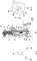
- FIG. 1 is a perspective view of an elevator system 101 including an elevator car 103, a counterweight 105, a tension member 107, a guide rail 109, a machine 111, a position reference system 113, and an elevator controller 115.
- the elevator car 103 and counterweight 105 are connected to each other by the tension member 107.
- the tension member 107 may include or be configured as, for example, ropes, steel cables, and/or coated-steel belts.
- the counterweight 105 is configured to balance a load of the elevator car 103 and is configured to facilitate movement of the elevator car 103 concurrently and in an opposite direction with respect to the counterweight 105 within an elevator shaft 117 (or hoistway) and along the guide rail 109.
- the tension member 107 engages the machine 111, which is part of an overhead structure of the elevator system 101.
- the machine 111 is configured to control movement between the elevator car 103 and the counterweight 105.
- the position reference system 113 may be mounted on a fixed part at the top of the elevator shaft 117, such as on a support or guide rail, and may be configured to provide position signals related to a position of the elevator car 103 within the elevator shaft 117. In other embodiments, the position reference system 113 may be directly mounted to a moving component of the machine 111, or may be located in other positions and/or configurations as known in the art.
- the position reference system 113 can be any device or mechanism for monitoring a position of an elevator car and/or counter weight, as known in the art.
- the position reference system 113 can be an encoder, sensor, or other system and can include velocity sensing, absolute position sensing, etc., as will be appreciated by those of skill in the art.
- the elevator controller 115 is located, as shown, in a controller room 121 of the elevator shaft 117 and is configured to control the operation of the elevator system 101, and particularly the elevator car 103.
- the elevator controller 115 may provide drive signals to the machine 111 to control the acceleration, deceleration, leveling, stopping, etc. of the elevator car 103.
- the elevator controller 115 may also be configured to receive position signals from the position reference system 113 or any other desired position reference device.
- the elevator car 103 may stop at one or more landings 125 as controlled by the elevator controller 115.
- the elevator controller 115 can be located and/or configured in other locations or positions within the elevator system 101. In one embodiment, the controller may be located remotely or in the cloud.
- the machine 111 may include a motor or similar driving mechanism.
- the machine 111 is configured to include an electrically driven motor.
- the power supply for the motor may be any power source, including a power grid, which, in combination with other components, is supplied to the motor.
- the machine 111 may include a traction sheave that imparts force to tension member 107 to move the elevator car 103 within elevator shaft 117.
- FIG. 1 is merely a non-limiting example presented for illustrative and explanatory purposes.
- a hoistway pit (pit) 200 (also referred to as a first architectural location) is illustrated.
- a person 210 such as a field technician may need to enter the hoistway pit (pit) 200, e.g., to perform maintenance.
- a stop switch 220 may be positioned within the pit 200.
- the stop switch 220 is electronically connected with the elevator controller 115 in the controller room 121 by a circuit 230 (shown schematically) having a holding relay 2310 which keeps the circuit 230 energized.
- the circuit 230 may be wired through the elevator shaft 117, e.g., along the guide rail 109.
- the stop switch 220 may include a housing 2205.
- a pull cap 2210 may extend forwardly from the housing 2205.
- the pull cap 2210 may be, e.g. a mushroom style pull cap (plunger).
- the stop switch 220 is in a stop configuration. This may disrupt power to the holding relay 2310, which may deenergize the circuit 230.
- the elevator controller 115 may stop the elevator car 103.
- the pull cap 2210 is retracted, i.e., pushed back toward the housing 2205, the stop switch 220 is in a run configuration, or vice versa.
- the holding relay 2310 may be energized, which may energize the circuit 230.
- the elevator controller 115 may run the elevator car 103.
- the stop switch 220 may include a motion sensor 2215 that may be integrated into the housing 2205.
- a switch controller 2220 of the stop switch 220 may be in electronic communication with the motion sensor 2215.
- the stop switch 220 may send a first signal to the holding relay 2310, via a holding relay controller 2325, to deenergize the circuit 230. As indicated above, this may result in the elevator controller 115 sensing the power loss in the circuit 230 and stopping the elevator car 103.
- the stop switch 220 may send a second signal to the holding relay 2310 to energize the circuit 230. As indicated above, this may result in the elevator controller 115 sensing the restored power in the circuit 230 and running the elevator car 103.
- FIG. 2 illustrates the housing 2205, the pull cap 2210 and the motion sensor 2215 of the stop switch 220.
- the stop switch 220 may further include an actuator 2225, illustrated schematically.
- the actuator 2225 may be a solenoid or other implement that is controlled, e.g., by the switch controller 2220.
- the actuator 2225 Upon the stop switch 220 sensing the person 210 in the pit 200, the actuator 2225 is controlled to push out the pull cap 2210. This action places the stop switch 220 in the stop configuration, or vice versa.
- the stop switch 220 when the stop switch 220 is in the stop configuration, power may be disrupted to the holding relay 2310, the circuit 230 may be deenergized, and the elevator controller 115 may stop the elevator car 103. Manually retracting (pushing back) the pull cap 2210 toward the housing 2205, the stop switch 220 is again in the run configuration. Upon entering the run configuration, the holding relay 2310 may be energized, which may energize the circuit 230. Upon sensing power in the circuit 230, the elevator controller 115 may run the elevator car 103.
- the person 210 has a mobile device (mobile phone) 240.
- the mobile phone 240 has a communication module 2410 and a geo-tracking module 2420, e.g., to track a specific location of the mobile phone 240.
- the mobile phone 240 and the holding relay 2310 are both configured to communicate over a wireless network 250, which may be a Bluetooth or other personal area network or similar low energy and rapid pairing network.
- the mobile phone 240 may transmit a third signal to the holding relay 2310.
- the third signal may be the same as the first signal, instructing the holding relay 2310 to deenergize the circuit 230. As indicated above, this may result in the elevator controller 115 sensing the power loss in the circuit 230 and stopping the elevator car 103.
- the signal is always transmitted by the mobile phone 240, e.g., so that the holding relay 2310 receives the signal whenever the mobile phone 240 is in close proximity to the pit 200.
- the communications may be calibrated so that the signal is received when the mobile phone 240 is in or near the pit 200.
- the mobile phone 240 may send a fourth signal to the holding relay 2310, or may send no additional signal.
- the fourth signal may be the same as the second signal, instructing the holding relay 2310 to energize the circuit 230.
- the holding relay 2310 may energize the circuit 230 after detecting no additional signal for a predetermined period of time. As indicated above, this may result in the elevator controller 115 sensing the restored power in the circuit 230 and running the elevator car 103.
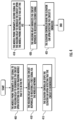
- FIG. 4 a flowchart shows a method of operating the elevator system 101 according to an embodiment.
- the method includes the mobile phone 240 transmitting the first signal to the holding relay 2310 to deenergize the circuit 230 upon the mobile phone 240 detecting via the geo-tracking module that it is in the pit 200, or when the mobile phone 240 is close enough to the holding relay 2310 such that the first signal is received.
- the method includes the holding relay 2310 deenergizing the circuit 230 responsive to receiving a first signal via the wireless network 250.
- the method includes the elevator controller 115 stopping an elevator car 103 upon detecting that the circuit 230 is deenergized.
- the elevator car 101 is controlled such that it remains a predefined distance of the pit 200, e.g., where the distance is measured in meters (feet) or levels.
- the method includes the mobile phone 240 transmitting the second signal to the holding relay 2310 to energize the circuit 230 upon the mobile phone 240 detecting that it has left the pit 200.
- the method includes the holding relay 2310 energizing the circuit 230 responsive to receiving the second signal.
- the method includes the elevator controller 115 running the elevator car 103 upon detecting that the circuit 230 is energized.
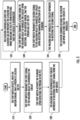
- FIG. 5 a further flowchart shows a non-claimed method of operating the elevator system 101 according to another embodiment.
- the method may include the stop switch 220 detecting, via the motion sensor 2215, that a person 210 (or another moving object) is located in the pit 200.
- the method may include the stop switch 220 transmitting a first signal to the holding relay 2310 to deenergize the circuit 230 upon detecting that the person 210 is in the pit 200.
- the method may further include actuating the plunger (e.g., biasing the pull cap 2210 away from the housing 2205 by the actuator 2225) when the stop switch 220 detects the person 210 in the pit 200.
- the stop switch 220 transmits the first signal to the hold relay 2310 without requiring the pull cap 2210 to be physically moved to an actuated position, e.g., away from the housing 2205.
- the method includes the holding relay 2310 deenergizing the circuit 230 responsive to receiving the first signal from the stop switch 220.
- the method includes the elevator controller 115 stopping an elevator car 103 or preventing the elevator car 103 from traveling to the pit 200 upon detecting that the circuit 230 is deenergized.
- the method may also include the stop switch 220 transmitting the second signal to the holding relay 2310 to energize the circuit 230 upon detecting, via the motion sensor 2215, that the person 210 has left the pit 200 or upon detecting manual retraction of the pull cap 2210.
- the method alternatively includes the stop switch 220 transmitting the second signal to the holding relay 2310 to energize the circuit upon detecting manual retraction of the plunger (pull cap 2210).
- the method includes the holding relay 2310 energizing the circuit 230 responsive to receiving the second signal.
- the method includes the elevator controller 115 running the elevator car 103 upon detecting that the circuit 230 is energized.
- embodiments can be in the form of processor-implemented processes and devices for practicing those processes, such as a processor.
- Embodiments can also be in the form of computer program code containing instructions embodied in tangible media, such as network cloud storage, SD cards, flash drives, floppy diskettes, CD ROMs, hard drives, or any other computer-readable storage medium, wherein, when the computer program code is loaded into and executed by a computer, the computer becomes a device for practicing the embodiments.
- Embodiments can also be in the form of computer program code, for example, whether stored in a storage medium, loaded into and/or executed by a computer, or transmitted over some transmission medium, loaded into and/or executed by a computer, or transmitted over some transmission medium, such as over electrical wiring or cabling, through fiber optics, or via electromagnetic radiation, wherein, when the computer program code is loaded into an executed by a computer, the computer becomes an device for practicing the embodiments.
- the computer program code segments configure the microprocessor to create specific logic circuits.
Landscapes
- Engineering & Computer Science (AREA)
- Automation & Control Theory (AREA)
- Computer Networks & Wireless Communication (AREA)
- Signal Processing (AREA)
- Elevator Control (AREA)
- Maintenance And Inspection Apparatuses For Elevators (AREA)
Description
- The embodiments herein relate to elevator systems and more specifically to a system and method for an emergency stop system for an elevator.
- Within an elevator pit, i.e., in an elevator hoistway, there may be a circumstance where a person such as a field technician needs access. This circumstance may pose a risk to such persons if an elevator car is allowed to run in the hoistway.
-
JP H02 169482 A US 2002/0117358 A1 describes an elevator safety installation with a shaft monitoring device which takes the elevator out of service in a dangerous situation.JP 2015198609 A1 - According to a first aspect of the present invention an elevator system is provided in accordance with claim 1.
- In some embodiments, the first architectural location is in or near a hoistway pit.
- In some embodiments, the holding relay is further configured to: energize the circuit responsive to receiving a second signal from the mobile device when the mobile device has left the first architectural location.
- In some embodiments, the elevator system includes: an elevator controller operationally connected to the circuit and configured to: stop an elevator car or prevent the elevator car from traveling to the first architectural location upon detecting that the circuit is deenergized; and run the elevator car upon detecting that the circuit is energized.
- In some embodiments, the elevator system includes: a hoistway, wherein: the elevator controller is in a controller room of the hoistway; the first architectural location is a hoistway pit of the hoistway; and the elevator car is positioned to move within the hoistway.
- The following descriptions should not be considered limiting in any way. With reference to the accompanying drawings, like elements are numbered alike:
-
FIG. 1 is a schematic illustration of an elevator system that may employ various embodiments of the present invention; -
FIG. 2 shows a stop switch of the elevator system; -
FIG. 3 shows a mobile device that communicates with the elevator system; -
FIG. 4 is a flowchart showing a method of operating the elevator system according to an embodiment of the present invention; and -
FIG. 5 is a flowchart showing another non-claimed method of operating the elevator system. - A detailed description of one or more embodiments of the disclosed apparatus and method are presented herein by way of exemplification and not limitation with reference to the Figures.
-
FIG. 1 is a perspective view of anelevator system 101 including anelevator car 103, acounterweight 105, atension member 107, aguide rail 109, amachine 111, aposition reference system 113, and anelevator controller 115. Theelevator car 103 andcounterweight 105 are connected to each other by thetension member 107. Thetension member 107 may include or be configured as, for example, ropes, steel cables, and/or coated-steel belts. Thecounterweight 105 is configured to balance a load of theelevator car 103 and is configured to facilitate movement of theelevator car 103 concurrently and in an opposite direction with respect to thecounterweight 105 within an elevator shaft 117 (or hoistway) and along theguide rail 109. - The
tension member 107 engages themachine 111, which is part of an overhead structure of theelevator system 101. Themachine 111 is configured to control movement between theelevator car 103 and thecounterweight 105. Theposition reference system 113 may be mounted on a fixed part at the top of the elevator shaft 117, such as on a support or guide rail, and may be configured to provide position signals related to a position of theelevator car 103 within the elevator shaft 117. In other embodiments, theposition reference system 113 may be directly mounted to a moving component of themachine 111, or may be located in other positions and/or configurations as known in the art. Theposition reference system 113 can be any device or mechanism for monitoring a position of an elevator car and/or counter weight, as known in the art. For example, without limitation, theposition reference system 113 can be an encoder, sensor, or other system and can include velocity sensing, absolute position sensing, etc., as will be appreciated by those of skill in the art. - The
elevator controller 115 is located, as shown, in acontroller room 121 of the elevator shaft 117 and is configured to control the operation of theelevator system 101, and particularly theelevator car 103. For example, theelevator controller 115 may provide drive signals to themachine 111 to control the acceleration, deceleration, leveling, stopping, etc. of theelevator car 103. Theelevator controller 115 may also be configured to receive position signals from theposition reference system 113 or any other desired position reference device. When moving up or down within the elevator shaft 117 alongguide rail 109, theelevator car 103 may stop at one ormore landings 125 as controlled by theelevator controller 115. Although shown in acontroller room 121, those of skill in the art will appreciate that theelevator controller 115 can be located and/or configured in other locations or positions within theelevator system 101. In one embodiment, the controller may be located remotely or in the cloud. - The
machine 111 may include a motor or similar driving mechanism. In accordance with embodiments of the disclosure, themachine 111 is configured to include an electrically driven motor. The power supply for the motor may be any power source, including a power grid, which, in combination with other components, is supplied to the motor. Themachine 111 may include a traction sheave that imparts force totension member 107 to move theelevator car 103 within elevator shaft 117. - Although shown and described with a roping system including
tension member 107, elevator systems that employ other methods and mechanisms of moving an elevator car within an elevator shaft may employ embodiments of the present disclosure. For example, embodiments may be employed in ropeless elevator systems using a linear motor to impart motion to an elevator car. Embodiments may also be employed in ropeless elevator systems using a hydraulic lift to impart motion to an elevator car.FIG. 1 is merely a non-limiting example presented for illustrative and explanatory purposes. - Remaining with
FIG. 1 , a hoistway pit (pit) 200 (also referred to as a first architectural location) is illustrated. Aperson 210 such as a field technician may need to enter the hoistway pit (pit) 200, e.g., to perform maintenance. Astop switch 220 may be positioned within thepit 200. Thestop switch 220 is electronically connected with theelevator controller 115 in thecontroller room 121 by a circuit 230 (shown schematically) having aholding relay 2310 which keeps thecircuit 230 energized. Thecircuit 230 may be wired through the elevator shaft 117, e.g., along theguide rail 109. - The
stop switch 220 may include ahousing 2205. Apull cap 2210 may extend forwardly from thehousing 2205. Thepull cap 2210 may be, e.g. a mushroom style pull cap (plunger). When thepull cap 2210 is pulled away from thehousing 2205, e.g., by theperson 210, thestop switch 220 is in a stop configuration. This may disrupt power to theholding relay 2310, which may deenergize thecircuit 230. Upon sensing the power loss in thecircuit 230, theelevator controller 115 may stop theelevator car 103. When thepull cap 2210 is retracted, i.e., pushed back toward thehousing 2205, thestop switch 220 is in a run configuration, or vice versa. Upon entering the run configuration, theholding relay 2310 may be energized, which may energize thecircuit 230. Upon sensing power in thecircuit 230, theelevator controller 115 may run theelevator car 103. - According to a non-claimed embodiment, the
stop switch 220 may include amotion sensor 2215 that may be integrated into thehousing 2205. Aswitch controller 2220 of thestop switch 220 may be in electronic communication with themotion sensor 2215. According to an embodiment upon sensing theperson 210 in thepit 200, thestop switch 220 may send a first signal to theholding relay 2310, via a holding relay controller 2325, to deenergize thecircuit 230. As indicated above, this may result in theelevator controller 115 sensing the power loss in thecircuit 230 and stopping theelevator car 103. Once the person 210 (or other moving object) is no longer detected by thestop switch 220 thestop switch 220 may send a second signal to the holdingrelay 2310 to energize thecircuit 230. As indicated above, this may result in theelevator controller 115 sensing the restored power in thecircuit 230 and running theelevator car 103. - Another non-claimed embodiment of the
stop switch 220 is illustrated inFIG. 2. FIG. 2 illustrates thehousing 2205, thepull cap 2210 and themotion sensor 2215 of thestop switch 220. Thestop switch 220 may further include an actuator 2225, illustrated schematically. The actuator 2225 may be a solenoid or other implement that is controlled, e.g., by theswitch controller 2220. Upon thestop switch 220 sensing theperson 210 in thepit 200, the actuator 2225 is controlled to push out thepull cap 2210. This action places thestop switch 220 in the stop configuration, or vice versa. As indicated, when thestop switch 220 is in the stop configuration, power may be disrupted to the holdingrelay 2310, thecircuit 230 may be deenergized, and theelevator controller 115 may stop theelevator car 103. Manually retracting (pushing back) thepull cap 2210 toward thehousing 2205, thestop switch 220 is again in the run configuration. Upon entering the run configuration, the holdingrelay 2310 may be energized, which may energize thecircuit 230. Upon sensing power in thecircuit 230, theelevator controller 115 may run theelevator car 103. - In a further non-claimed embodiment, the
person 210 has a mobile device (mobile phone) 240. As illustrated inFIG. 3 , themobile phone 240 has acommunication module 2410 and a geo-tracking module 2420, e.g., to track a specific location of themobile phone 240. Themobile phone 240 and the holdingrelay 2310 are both configured to communicate over awireless network 250, which may be a Bluetooth or other personal area network or similar low energy and rapid pairing network. - When the
mobile phone 240 determines that theperson 210 is in thepit 200, themobile phone 240 may transmit a third signal to the holdingrelay 2310. The third signal may be the same as the first signal, instructing the holdingrelay 2310 to deenergize thecircuit 230. As indicated above, this may result in theelevator controller 115 sensing the power loss in thecircuit 230 and stopping theelevator car 103. Alternatively, rather than transmitting a third signal only upon determining theperson 210 is in thepit 200, the signal is always transmitted by themobile phone 240, e.g., so that the holdingrelay 2310 receives the signal whenever themobile phone 240 is in close proximity to thepit 200. For example, the communications may be calibrated so that the signal is received when themobile phone 240 is in or near thepit 200. - Once the
mobile phone 240 detects that theperson 210 is no longer in thepit 200, themobile phone 240 may send a fourth signal to the holdingrelay 2310, or may send no additional signal. The fourth signal may be the same as the second signal, instructing the holdingrelay 2310 to energize thecircuit 230. Or the holdingrelay 2310 may energize thecircuit 230 after detecting no additional signal for a predetermined period of time. As indicated above, this may result in theelevator controller 115 sensing the restored power in thecircuit 230 and running theelevator car 103. - With the above configurations, human error of forgetting to engage the stop switch is removed.
- Turning to
FIG. 4 , a flowchart shows a method of operating theelevator system 101 according to an embodiment. As shown inblock 405 the method includes themobile phone 240 transmitting the first signal to the holdingrelay 2310 to deenergize thecircuit 230 upon themobile phone 240 detecting via the geo-tracking module that it is in thepit 200, or when themobile phone 240 is close enough to the holdingrelay 2310 such that the first signal is received. - As shown in
block 410 the method includes the holdingrelay 2310 deenergizing thecircuit 230 responsive to receiving a first signal via thewireless network 250. As shown inblock 415 the method includes theelevator controller 115 stopping anelevator car 103 upon detecting that thecircuit 230 is deenergized. In one embodiment, instead of stopping theelevator car 101, theelevator car 101 is controlled such that it remains a predefined distance of thepit 200, e.g., where the distance is measured in meters (feet) or levels. - As shown in
block 418 the method includes themobile phone 240 transmitting the second signal to the holdingrelay 2310 to energize thecircuit 230 upon themobile phone 240 detecting that it has left thepit 200. As shown inblock 420 the method includes the holdingrelay 2310 energizing thecircuit 230 responsive to receiving the second signal. As shown inblock 425 the method includes theelevator controller 115 running theelevator car 103 upon detecting that thecircuit 230 is energized. - Turning to
FIG. 5 , a further flowchart shows a non-claimed method of operating theelevator system 101 according to another embodiment. As shown inblock 510, in one embodiment the method may include thestop switch 220 detecting, via themotion sensor 2215, that a person 210 (or another moving object) is located in thepit 200. As shown inblock 520 the method may include thestop switch 220 transmitting a first signal to the holdingrelay 2310 to deenergize thecircuit 230 upon detecting that theperson 210 is in thepit 200. In certain embodiments, as shown inblock 520, the method may further include actuating the plunger (e.g., biasing thepull cap 2210 away from thehousing 2205 by the actuator 2225) when thestop switch 220 detects theperson 210 in thepit 200. However, within the scope of the disclosure are embodiments in which thestop switch 220 transmits the first signal to thehold relay 2310 without requiring thepull cap 2210 to be physically moved to an actuated position, e.g., away from thehousing 2205. - As shown in
block 530 the method includes the holdingrelay 2310 deenergizing thecircuit 230 responsive to receiving the first signal from thestop switch 220. As shown inblock 535 the method includes theelevator controller 115 stopping anelevator car 103 or preventing theelevator car 103 from traveling to thepit 200 upon detecting that thecircuit 230 is deenergized. - As shown in
block 540, in one embodiment the method may also include thestop switch 220 transmitting the second signal to the holdingrelay 2310 to energize thecircuit 230 upon detecting, via themotion sensor 2215, that theperson 210 has left thepit 200 or upon detecting manual retraction of thepull cap 2210. As further shown inblock 540, the method alternatively includes thestop switch 220 transmitting the second signal to the holdingrelay 2310 to energize the circuit upon detecting manual retraction of the plunger (pull cap 2210). - As shown in
block 545 the method includes the holdingrelay 2310 energizing thecircuit 230 responsive to receiving the second signal. As shown inblock 550 the method includes theelevator controller 115 running theelevator car 103 upon detecting that thecircuit 230 is energized. - As described above, embodiments can be in the form of processor-implemented processes and devices for practicing those processes, such as a processor. Embodiments can also be in the form of computer program code containing instructions embodied in tangible media, such as network cloud storage, SD cards, flash drives, floppy diskettes, CD ROMs, hard drives, or any other computer-readable storage medium, wherein, when the computer program code is loaded into and executed by a computer, the computer becomes a device for practicing the embodiments. Embodiments can also be in the form of computer program code, for example, whether stored in a storage medium, loaded into and/or executed by a computer, or transmitted over some transmission medium, loaded into and/or executed by a computer, or transmitted over some transmission medium, such as over electrical wiring or cabling, through fiber optics, or via electromagnetic radiation, wherein, when the computer program code is loaded into an executed by a computer, the computer becomes an device for practicing the embodiments. When implemented on a general-purpose microprocessor, the computer program code segments configure the microprocessor to create specific logic circuits.
- The terminology used herein is for the purpose of describing particular embodiments only and is not intended to be limiting of the present disclosure. As used herein, the singular forms "a", "an" and "the" are intended to include the plural forms as well, unless the context clearly indicates otherwise. It will be further understood that the terms "comprises" and/or "comprising," when used in this specification, specify the presence of stated features, integers, steps, operations, elements, and/or components, but do not preclude the presence or addition of one or more other features, integers, steps, operations, element components, and/or groups thereof.
- Those of skill in the art will appreciate that various example embodiments are shown and described herein, each having certain features in the particular embodiments, but the present disclosure is not thus limited, but is only limited by the appended claims. Rather, the present disclosure can be modified to incorporate any number of variations, alterations, substitutions, combinations, or sub-combinations not heretofore described, but which are commensurate with the scope of the appended claims. Additionally, while various embodiments of the present disclosure have been described, it is to be understood that aspects of the present disclosure may include only some of the described embodiments. Accordingly, the present disclosure is not to be seen as limited by the foregoing description, but is only limited by the scope of the appended claims.
Claims (5)
- An elevator system (101) characterized by comprising:a stop switch (220) electronically connected with an elevator controller (115) in a controller room (121) by a circuit (230) having a holding relay (2310), the holding relay (2310) configured to keep the circuit energized and to deenergize the circuit (230),the holding relay (2310) configured to communicate over a wireless network (250) with a mobile device (240),wherein the holding relay (2310) is configured to:
deenergize the circuit responsive to receiving a first signal via the wireless network (250) from the mobile device (240), indicative of the mobile device (240) being in or near a first architectural location (200). - The elevator system (101) of claim 1, wherein:
the holding relay (2310) is further configured to:
energize the circuit (230) responsive to receiving a second signal from the mobile device (240) when the mobile device (240) has left the first architectural location (200). - The elevator system (101) of any preceding claim, wherein the first architectural location is a hoistway pit (200), or in or near a hoistway pit (200).
- The elevator system (101) of any preceding claim, including:
an elevator controller (115) operationally connected to the circuit (230) and configured to:stop an elevator car (103) or prevent the elevator car (103) from traveling to the first architectural location (200) upon detecting that the circuit (230) is deenergized;
andrun the elevator car (103) upon detecting that the circuit (230) is energized. - The elevator system (101) of claim 4, including:
a hoistway (117), wherein:the elevator controller (115) is in a controller room (121) of the hoistway (117);the first architectural location is a hoistway pit (200) of the hoistway (117); andthe elevator car (103) is positioned to move within the hoistway (117).
Priority Applications (1)
| Application Number | Priority Date | Filing Date | Title |
|---|---|---|---|
| EP24167713.7A EP4400466A1 (en) | 2019-11-28 | 2020-11-27 | Emergency stop system for elevator |
Applications Claiming Priority (1)
| Application Number | Priority Date | Filing Date | Title |
|---|---|---|---|
| US16/699,019 US12157657B2 (en) | 2019-11-28 | 2019-11-28 | Emergency stop system for elevator |
Related Child Applications (2)
| Application Number | Title | Priority Date | Filing Date |
|---|---|---|---|
| EP24167713.7A Division EP4400466A1 (en) | 2019-11-28 | 2020-11-27 | Emergency stop system for elevator |
| EP24167713.7A Division-Into EP4400466A1 (en) | 2019-11-28 | 2020-11-27 | Emergency stop system for elevator |
Publications (2)
| Publication Number | Publication Date |
|---|---|
| EP3828115A1 EP3828115A1 (en) | 2021-06-02 |
| EP3828115B1 true EP3828115B1 (en) | 2024-08-07 |
Family
ID=73642763
Family Applications (2)
| Application Number | Title | Priority Date | Filing Date |
|---|---|---|---|
| EP20210484.0A Active EP3828115B1 (en) | 2019-11-28 | 2020-11-27 | Emergency stop system for elevator |
| EP24167713.7A Pending EP4400466A1 (en) | 2019-11-28 | 2020-11-27 | Emergency stop system for elevator |
Family Applications After (1)
| Application Number | Title | Priority Date | Filing Date |
|---|---|---|---|
| EP24167713.7A Pending EP4400466A1 (en) | 2019-11-28 | 2020-11-27 | Emergency stop system for elevator |
Country Status (3)
| Country | Link |
|---|---|
| US (1) | US12157657B2 (en) |
| EP (2) | EP3828115B1 (en) |
| CN (1) | CN112850402A (en) |
Cited By (1)
| Publication number | Priority date | Publication date | Assignee | Title |
|---|---|---|---|---|
| US20210155447A1 (en) * | 2019-11-26 | 2021-05-27 | Otis Elevator Company | Safety brake trigger |
Families Citing this family (1)
| Publication number | Priority date | Publication date | Assignee | Title |
|---|---|---|---|---|
| US12157657B2 (en) * | 2019-11-28 | 2024-12-03 | Otis Elevator Company | Emergency stop system for elevator |
Family Cites Families (31)
| Publication number | Priority date | Publication date | Assignee | Title |
|---|---|---|---|---|
| JPH02169482A (en) | 1988-12-19 | 1990-06-29 | Toshiba Corp | Controller for elevator |
| US6202797B1 (en) * | 1999-08-26 | 2001-03-20 | Otis Elevator Company | Automatic protection of elevator mechanics |
| DE10108772A1 (en) * | 2001-02-23 | 2002-11-21 | Otis Elevator Co | Elevator safety device |
| US6467585B1 (en) | 2001-07-05 | 2002-10-22 | Otis Elevator Company | Wireless safety chain for elevator system |
| US7258202B1 (en) | 2004-05-10 | 2007-08-21 | Inventio Ag | Creation of temporary safety spaces for elevators |
| US7954606B2 (en) * | 2005-10-05 | 2011-06-07 | Otis Elevator Company | Elevator system control responsive to hoistway access detection |
| FI121423B (en) | 2009-04-23 | 2010-11-15 | Kone Corp | Safety arrangement for a lift |
| KR101818270B1 (en) | 2009-12-21 | 2018-01-12 | 인벤티오 아게 | Shaft access enabling device of an elevator system |
| JP2011162275A (en) | 2010-02-04 | 2011-08-25 | Toshiba Elevator Co Ltd | Emergency stopping device of elevator |
| RU2564433C2 (en) | 2011-05-10 | 2015-09-27 | Отис Элевэйтор Компани | Monitoring remote control of hoisting system |
| JP5526092B2 (en) * | 2011-09-06 | 2014-06-18 | 株式会社日立製作所 | Electronic elevator |
| WO2013055346A1 (en) * | 2011-10-14 | 2013-04-18 | Otis Elevator Company | Elevator system with messaging for automated maintenance |
| PL2900581T3 (en) | 2012-09-25 | 2017-05-31 | Inventio Ag | Method for resetting a safety system of an elevator installation |
| WO2014095511A1 (en) | 2012-12-21 | 2014-06-26 | Inventio Ag | Monitoring of a hazard zone |
| JP2014198609A (en) | 2013-03-29 | 2014-10-23 | 株式会社日立ビルシステム | Maintenance operation device and maintenance operation system for elevator |
| AU2014304656B2 (en) * | 2013-08-09 | 2017-06-01 | Inventio Ag | Communication method for a lift system |
| JP6247888B2 (en) | 2013-10-08 | 2017-12-13 | 株式会社日立ビルシステム | Elevator inspection safety equipment |
| EP3012217B8 (en) | 2014-10-21 | 2017-08-02 | KONE Corporation | Safety system for elevator |
| CN107848742B (en) | 2015-07-01 | 2020-02-07 | 奥的斯电梯公司 | Elevator control system and elevator system comprising same |
| EP3187449A1 (en) | 2015-12-30 | 2017-07-05 | Kone Corporation | Mechanism for improving safety for an elevator system |
| WO2018050253A1 (en) | 2016-09-19 | 2018-03-22 | Kone Corporation | Method for setting an elevator into service mode |
| US9998581B1 (en) * | 2017-01-13 | 2018-06-12 | Otis Elevator Company | Communication system and method of communication in an elevator operating environment |
| US20180201474A1 (en) * | 2017-01-13 | 2018-07-19 | Otis Elevator Company | Mobile device identification in elevator communication system and method |
| US10112802B2 (en) * | 2017-01-30 | 2018-10-30 | Otis Elevator Company | Elevator service person collision protection system |
| JP6393365B1 (en) * | 2017-04-28 | 2018-09-19 | 東芝エレベータ株式会社 | Elevator wireless communication system |
| US10906776B2 (en) * | 2017-08-30 | 2021-02-02 | Otis Elevator Company | Work area technician warning system |
| US20190084796A1 (en) | 2017-09-15 | 2019-03-21 | Otis Elevator Company | Restricted access area safety system |
| CN108275522A (en) * | 2018-02-07 | 2018-07-13 | 上海有个机器人有限公司 | Intelligent mobile equipment boarding method, system and its elevator control gear interior exhale device |
| US11072515B2 (en) * | 2018-03-27 | 2021-07-27 | Otis Elevator Company | Automated elevator maintenance mode initiation |
| US20200122965A1 (en) * | 2018-10-19 | 2020-04-23 | Otis Elevator Company | System for providing elevator service |
| US12157657B2 (en) * | 2019-11-28 | 2024-12-03 | Otis Elevator Company | Emergency stop system for elevator |
-
2019
- 2019-11-28 US US16/699,019 patent/US12157657B2/en active Active
-
2020
- 2020-11-27 CN CN202011363094.0A patent/CN112850402A/en active Pending
- 2020-11-27 EP EP20210484.0A patent/EP3828115B1/en active Active
- 2020-11-27 EP EP24167713.7A patent/EP4400466A1/en active Pending
Cited By (2)
| Publication number | Priority date | Publication date | Assignee | Title |
|---|---|---|---|---|
| US20210155447A1 (en) * | 2019-11-26 | 2021-05-27 | Otis Elevator Company | Safety brake trigger |
| US12486140B2 (en) * | 2019-11-26 | 2025-12-02 | Otis Elevator Company | Safety brake trigger |
Also Published As
| Publication number | Publication date |
|---|---|
| US20210163260A1 (en) | 2021-06-03 |
| CN112850402A (en) | 2021-05-28 |
| EP4400466A1 (en) | 2024-07-17 |
| US12157657B2 (en) | 2024-12-03 |
| EP3828115A1 (en) | 2021-06-02 |
Similar Documents
| Publication | Publication Date | Title |
|---|---|---|
| CN108455396B (en) | Elevator safety system and method for monitoring an elevator system | |
| EP3628622B1 (en) | Validation of elevator call passenger boarding | |
| EP2947034A1 (en) | An elevator | |
| EP3587323A1 (en) | Elevator system | |
| CN110921449B (en) | Sensor-based shutdown detection for elevator systems | |
| EP3232177A1 (en) | Building settling detection | |
| EP3960673B1 (en) | Elevator systems | |
| CN110817614A (en) | Improving the transport capacity of an elevator system | |
| CN113371569B (en) | Elevator safety system | |
| EP3599199A2 (en) | Capacity shifting between partially-overlapping elevator groups | |
| EP3828115B1 (en) | Emergency stop system for elevator | |
| EP3666710B1 (en) | Safety system based on hoistway access detection | |
| EP3650384B1 (en) | System for monitoring lobby activity to determine whether to cancel elevator service | |
| CN111847154B (en) | Solutions for operating elevators | |
| KR20110084553A (en) | Elevator braking control | |
| CN115402901A (en) | Elevator system | |
| US20190330015A1 (en) | Elevator safety system | |
| EP3643660B1 (en) | System for providing elevator service | |
| CN111170102B (en) | Method and apparatus for monitoring elevator systems | |
| EP4477602A1 (en) | Elevator system including pit safety interface | |
| EP4019447A1 (en) | Method for triggering automatic elevator calls | |
| EP3594164B1 (en) | Gesture controlled door opening for elevators considering angular movement and orientation | |
| HK40032485A (en) | A solution for operating an elevator |
Legal Events
| Date | Code | Title | Description |
|---|---|---|---|
| PUAI | Public reference made under article 153(3) epc to a published international application that has entered the european phase |
Free format text: ORIGINAL CODE: 0009012 |
|
| STAA | Information on the status of an ep patent application or granted ep patent |
Free format text: STATUS: THE APPLICATION HAS BEEN PUBLISHED |
|
| AK | Designated contracting states |
Kind code of ref document: A1 Designated state(s): AL AT BE BG CH CY CZ DE DK EE ES FI FR GB GR HR HU IE IS IT LI LT LU LV MC MK MT NL NO PL PT RO RS SE SI SK SM TR |
|
| STAA | Information on the status of an ep patent application or granted ep patent |
Free format text: STATUS: REQUEST FOR EXAMINATION WAS MADE |
|
| 17P | Request for examination filed |
Effective date: 20211202 |
|
| RBV | Designated contracting states (corrected) |
Designated state(s): AL AT BE BG CH CY CZ DE DK EE ES FI FR GB GR HR HU IE IS IT LI LT LU LV MC MK MT NL NO PL PT RO RS SE SI SK SM TR |
|
| STAA | Information on the status of an ep patent application or granted ep patent |
Free format text: STATUS: EXAMINATION IS IN PROGRESS |
|
| 17Q | First examination report despatched |
Effective date: 20220804 |
|
| GRAP | Despatch of communication of intention to grant a patent |
Free format text: ORIGINAL CODE: EPIDOSNIGR1 |
|
| STAA | Information on the status of an ep patent application or granted ep patent |
Free format text: STATUS: GRANT OF PATENT IS INTENDED |
|
| INTG | Intention to grant announced |
Effective date: 20230525 |
|
| GRAJ | Information related to disapproval of communication of intention to grant by the applicant or resumption of examination proceedings by the epo deleted |
Free format text: ORIGINAL CODE: EPIDOSDIGR1 |
|
| STAA | Information on the status of an ep patent application or granted ep patent |
Free format text: STATUS: EXAMINATION IS IN PROGRESS |
|
| INTC | Intention to grant announced (deleted) | ||
| GRAP | Despatch of communication of intention to grant a patent |
Free format text: ORIGINAL CODE: EPIDOSNIGR1 |
|
| STAA | Information on the status of an ep patent application or granted ep patent |
Free format text: STATUS: GRANT OF PATENT IS INTENDED |
|
| INTG | Intention to grant announced |
Effective date: 20240306 |
|
| GRAS | Grant fee paid |
Free format text: ORIGINAL CODE: EPIDOSNIGR3 |
|
| GRAA | (expected) grant |
Free format text: ORIGINAL CODE: 0009210 |
|
| STAA | Information on the status of an ep patent application or granted ep patent |
Free format text: STATUS: THE PATENT HAS BEEN GRANTED |
|
| AK | Designated contracting states |
Kind code of ref document: B1 Designated state(s): AL AT BE BG CH CY CZ DE DK EE ES FI FR GB GR HR HU IE IS IT LI LT LU LV MC MK MT NL NO PL PT RO RS SE SI SK SM TR |
|
| REG | Reference to a national code |
Ref country code: GB Ref legal event code: FG4D |
|
| REG | Reference to a national code |
Ref country code: CH Ref legal event code: EP |
|
| REG | Reference to a national code |
Ref country code: IE Ref legal event code: FG4D |
|
| REG | Reference to a national code |
Ref country code: DE Ref legal event code: R096 Ref document number: 602020035230 Country of ref document: DE |
|
| REG | Reference to a national code |
Ref country code: LT Ref legal event code: MG9D |
|
| REG | Reference to a national code |
Ref country code: NL Ref legal event code: MP Effective date: 20240807 |
|
| PGFP | Annual fee paid to national office [announced via postgrant information from national office to epo] |
Ref country code: DE Payment date: 20241022 Year of fee payment: 5 |
|
| PG25 | Lapsed in a contracting state [announced via postgrant information from national office to epo] |
Ref country code: NO Free format text: LAPSE BECAUSE OF FAILURE TO SUBMIT A TRANSLATION OF THE DESCRIPTION OR TO PAY THE FEE WITHIN THE PRESCRIBED TIME-LIMIT Effective date: 20241107 |
|
| REG | Reference to a national code |
Ref country code: AT Ref legal event code: MK05 Ref document number: 1710731 Country of ref document: AT Kind code of ref document: T Effective date: 20240807 |
|
| PG25 | Lapsed in a contracting state [announced via postgrant information from national office to epo] |
Ref country code: GR Free format text: LAPSE BECAUSE OF FAILURE TO SUBMIT A TRANSLATION OF THE DESCRIPTION OR TO PAY THE FEE WITHIN THE PRESCRIBED TIME-LIMIT Effective date: 20241108 Ref country code: FI Free format text: LAPSE BECAUSE OF FAILURE TO SUBMIT A TRANSLATION OF THE DESCRIPTION OR TO PAY THE FEE WITHIN THE PRESCRIBED TIME-LIMIT Effective date: 20240807 Ref country code: NL Free format text: LAPSE BECAUSE OF FAILURE TO SUBMIT A TRANSLATION OF THE DESCRIPTION OR TO PAY THE FEE WITHIN THE PRESCRIBED TIME-LIMIT Effective date: 20240807 Ref country code: PL Free format text: LAPSE BECAUSE OF FAILURE TO SUBMIT A TRANSLATION OF THE DESCRIPTION OR TO PAY THE FEE WITHIN THE PRESCRIBED TIME-LIMIT Effective date: 20240807 Ref country code: PT Free format text: LAPSE BECAUSE OF FAILURE TO SUBMIT A TRANSLATION OF THE DESCRIPTION OR TO PAY THE FEE WITHIN THE PRESCRIBED TIME-LIMIT Effective date: 20241209 |
|
| PG25 | Lapsed in a contracting state [announced via postgrant information from national office to epo] |
Ref country code: BG Free format text: LAPSE BECAUSE OF FAILURE TO SUBMIT A TRANSLATION OF THE DESCRIPTION OR TO PAY THE FEE WITHIN THE PRESCRIBED TIME-LIMIT Effective date: 20240807 |
|
| PG25 | Lapsed in a contracting state [announced via postgrant information from national office to epo] |
Ref country code: LV Free format text: LAPSE BECAUSE OF FAILURE TO SUBMIT A TRANSLATION OF THE DESCRIPTION OR TO PAY THE FEE WITHIN THE PRESCRIBED TIME-LIMIT Effective date: 20240807 |
|
| PG25 | Lapsed in a contracting state [announced via postgrant information from national office to epo] |
Ref country code: IS Free format text: LAPSE BECAUSE OF FAILURE TO SUBMIT A TRANSLATION OF THE DESCRIPTION OR TO PAY THE FEE WITHIN THE PRESCRIBED TIME-LIMIT Effective date: 20241207 Ref country code: AT Free format text: LAPSE BECAUSE OF FAILURE TO SUBMIT A TRANSLATION OF THE DESCRIPTION OR TO PAY THE FEE WITHIN THE PRESCRIBED TIME-LIMIT Effective date: 20240807 |
|
| PGFP | Annual fee paid to national office [announced via postgrant information from national office to epo] |
Ref country code: FR Payment date: 20241022 Year of fee payment: 5 |
|
| PG25 | Lapsed in a contracting state [announced via postgrant information from national office to epo] |
Ref country code: HR Free format text: LAPSE BECAUSE OF FAILURE TO SUBMIT A TRANSLATION OF THE DESCRIPTION OR TO PAY THE FEE WITHIN THE PRESCRIBED TIME-LIMIT Effective date: 20240807 |
|
| PG25 | Lapsed in a contracting state [announced via postgrant information from national office to epo] |
Ref country code: ES Free format text: LAPSE BECAUSE OF FAILURE TO SUBMIT A TRANSLATION OF THE DESCRIPTION OR TO PAY THE FEE WITHIN THE PRESCRIBED TIME-LIMIT Effective date: 20240807 Ref country code: RS Free format text: LAPSE BECAUSE OF FAILURE TO SUBMIT A TRANSLATION OF THE DESCRIPTION OR TO PAY THE FEE WITHIN THE PRESCRIBED TIME-LIMIT Effective date: 20241107 |
|
| PG25 | Lapsed in a contracting state [announced via postgrant information from national office to epo] |
Ref country code: RS Free format text: LAPSE BECAUSE OF FAILURE TO SUBMIT A TRANSLATION OF THE DESCRIPTION OR TO PAY THE FEE WITHIN THE PRESCRIBED TIME-LIMIT Effective date: 20241107 Ref country code: PT Free format text: LAPSE BECAUSE OF FAILURE TO SUBMIT A TRANSLATION OF THE DESCRIPTION OR TO PAY THE FEE WITHIN THE PRESCRIBED TIME-LIMIT Effective date: 20241209 Ref country code: PL Free format text: LAPSE BECAUSE OF FAILURE TO SUBMIT A TRANSLATION OF THE DESCRIPTION OR TO PAY THE FEE WITHIN THE PRESCRIBED TIME-LIMIT Effective date: 20240807 Ref country code: NO Free format text: LAPSE BECAUSE OF FAILURE TO SUBMIT A TRANSLATION OF THE DESCRIPTION OR TO PAY THE FEE WITHIN THE PRESCRIBED TIME-LIMIT Effective date: 20241107 Ref country code: NL Free format text: LAPSE BECAUSE OF FAILURE TO SUBMIT A TRANSLATION OF THE DESCRIPTION OR TO PAY THE FEE WITHIN THE PRESCRIBED TIME-LIMIT Effective date: 20240807 Ref country code: LV Free format text: LAPSE BECAUSE OF FAILURE TO SUBMIT A TRANSLATION OF THE DESCRIPTION OR TO PAY THE FEE WITHIN THE PRESCRIBED TIME-LIMIT Effective date: 20240807 Ref country code: IS Free format text: LAPSE BECAUSE OF FAILURE TO SUBMIT A TRANSLATION OF THE DESCRIPTION OR TO PAY THE FEE WITHIN THE PRESCRIBED TIME-LIMIT Effective date: 20241207 Ref country code: HR Free format text: LAPSE BECAUSE OF FAILURE TO SUBMIT A TRANSLATION OF THE DESCRIPTION OR TO PAY THE FEE WITHIN THE PRESCRIBED TIME-LIMIT Effective date: 20240807 Ref country code: GR Free format text: LAPSE BECAUSE OF FAILURE TO SUBMIT A TRANSLATION OF THE DESCRIPTION OR TO PAY THE FEE WITHIN THE PRESCRIBED TIME-LIMIT Effective date: 20241108 Ref country code: FI Free format text: LAPSE BECAUSE OF FAILURE TO SUBMIT A TRANSLATION OF THE DESCRIPTION OR TO PAY THE FEE WITHIN THE PRESCRIBED TIME-LIMIT Effective date: 20240807 Ref country code: ES Free format text: LAPSE BECAUSE OF FAILURE TO SUBMIT A TRANSLATION OF THE DESCRIPTION OR TO PAY THE FEE WITHIN THE PRESCRIBED TIME-LIMIT Effective date: 20240807 Ref country code: BG Free format text: LAPSE BECAUSE OF FAILURE TO SUBMIT A TRANSLATION OF THE DESCRIPTION OR TO PAY THE FEE WITHIN THE PRESCRIBED TIME-LIMIT Effective date: 20240807 Ref country code: AT Free format text: LAPSE BECAUSE OF FAILURE TO SUBMIT A TRANSLATION OF THE DESCRIPTION OR TO PAY THE FEE WITHIN THE PRESCRIBED TIME-LIMIT Effective date: 20240807 |
|
| PG25 | Lapsed in a contracting state [announced via postgrant information from national office to epo] |
Ref country code: DK Free format text: LAPSE BECAUSE OF FAILURE TO SUBMIT A TRANSLATION OF THE DESCRIPTION OR TO PAY THE FEE WITHIN THE PRESCRIBED TIME-LIMIT Effective date: 20240807 Ref country code: SM Free format text: LAPSE BECAUSE OF FAILURE TO SUBMIT A TRANSLATION OF THE DESCRIPTION OR TO PAY THE FEE WITHIN THE PRESCRIBED TIME-LIMIT Effective date: 20240807 |
|
| PG25 | Lapsed in a contracting state [announced via postgrant information from national office to epo] |
Ref country code: EE Free format text: LAPSE BECAUSE OF FAILURE TO SUBMIT A TRANSLATION OF THE DESCRIPTION OR TO PAY THE FEE WITHIN THE PRESCRIBED TIME-LIMIT Effective date: 20240807 |
|
| PG25 | Lapsed in a contracting state [announced via postgrant information from national office to epo] |
Ref country code: CZ Free format text: LAPSE BECAUSE OF FAILURE TO SUBMIT A TRANSLATION OF THE DESCRIPTION OR TO PAY THE FEE WITHIN THE PRESCRIBED TIME-LIMIT Effective date: 20240807 |
|
| PG25 | Lapsed in a contracting state [announced via postgrant information from national office to epo] |
Ref country code: SK Free format text: LAPSE BECAUSE OF FAILURE TO SUBMIT A TRANSLATION OF THE DESCRIPTION OR TO PAY THE FEE WITHIN THE PRESCRIBED TIME-LIMIT Effective date: 20240807 |
|
| REG | Reference to a national code |
Ref country code: DE Ref legal event code: R097 Ref document number: 602020035230 Country of ref document: DE |
|
| PLBE | No opposition filed within time limit |
Free format text: ORIGINAL CODE: 0009261 |
|
| STAA | Information on the status of an ep patent application or granted ep patent |
Free format text: STATUS: NO OPPOSITION FILED WITHIN TIME LIMIT |
|
| REG | Reference to a national code |
Ref country code: CH Ref legal event code: PL |
|
| PG25 | Lapsed in a contracting state [announced via postgrant information from national office to epo] |
Ref country code: MC Free format text: LAPSE BECAUSE OF FAILURE TO SUBMIT A TRANSLATION OF THE DESCRIPTION OR TO PAY THE FEE WITHIN THE PRESCRIBED TIME-LIMIT Effective date: 20240807 |
|
| PG25 | Lapsed in a contracting state [announced via postgrant information from national office to epo] |
Ref country code: LU Free format text: LAPSE BECAUSE OF NON-PAYMENT OF DUE FEES Effective date: 20241127 |
|
| REG | Reference to a national code |
Ref country code: CH Ref legal event code: PL |
|
| 26N | No opposition filed |
Effective date: 20250508 |
|
| GBPC | Gb: european patent ceased through non-payment of renewal fee |
Effective date: 20241127 |
|
| PG25 | Lapsed in a contracting state [announced via postgrant information from national office to epo] |
Ref country code: CH Free format text: LAPSE BECAUSE OF NON-PAYMENT OF DUE FEES Effective date: 20241130 |
|
| REG | Reference to a national code |
Ref country code: BE Ref legal event code: MM Effective date: 20241130 |
|
| PG25 | Lapsed in a contracting state [announced via postgrant information from national office to epo] |
Ref country code: SE Free format text: LAPSE BECAUSE OF FAILURE TO SUBMIT A TRANSLATION OF THE DESCRIPTION OR TO PAY THE FEE WITHIN THE PRESCRIBED TIME-LIMIT Effective date: 20240807 |
|
| PG25 | Lapsed in a contracting state [announced via postgrant information from national office to epo] |
Ref country code: GB Free format text: LAPSE BECAUSE OF NON-PAYMENT OF DUE FEES Effective date: 20241127 Ref country code: BE Free format text: LAPSE BECAUSE OF NON-PAYMENT OF DUE FEES Effective date: 20241130 |
|
| PG25 | Lapsed in a contracting state [announced via postgrant information from national office to epo] |
Ref country code: IE Free format text: LAPSE BECAUSE OF NON-PAYMENT OF DUE FEES Effective date: 20241127 |
|
| PG25 | Lapsed in a contracting state [announced via postgrant information from national office to epo] |
Ref country code: RO Free format text: LAPSE BECAUSE OF FAILURE TO SUBMIT A TRANSLATION OF THE DESCRIPTION OR TO PAY THE FEE WITHIN THE PRESCRIBED TIME-LIMIT Effective date: 20240807 |