EP3827775A1 - Transporteur mit verriegelungseinrichtung - Google Patents
Transporteur mit verriegelungseinrichtung Download PDFInfo
- Publication number
- EP3827775A1 EP3827775A1 EP20208106.3A EP20208106A EP3827775A1 EP 3827775 A1 EP3827775 A1 EP 3827775A1 EP 20208106 A EP20208106 A EP 20208106A EP 3827775 A1 EP3827775 A1 EP 3827775A1
- Authority
- EP
- European Patent Office
- Prior art keywords
- conveyor
- transporter
- locking
- latching
- locking element
- Prior art date
- Legal status (The legal status is an assumption and is not a legal conclusion. Google has not performed a legal analysis and makes no representation as to the accuracy of the status listed.)
- Granted
Links
Images

Classifications
-
- A—HUMAN NECESSITIES
- A61—MEDICAL OR VETERINARY SCIENCE; HYGIENE
- A61B—DIAGNOSIS; SURGERY; IDENTIFICATION
- A61B18/00—Surgical instruments, devices or methods for transferring non-mechanical forms of energy to or from the body
- A61B18/04—Surgical instruments, devices or methods for transferring non-mechanical forms of energy to or from the body by heating
- A61B18/12—Surgical instruments, devices or methods for transferring non-mechanical forms of energy to or from the body by heating by passing a current through the tissue to be heated, e.g. high-frequency current
- A61B18/14—Probes or electrodes therefor
- A61B18/149—Probes or electrodes therefor bow shaped or with rotatable body at cantilever end, e.g. for resectoscopes, or coagulating rollers
-
- A—HUMAN NECESSITIES
- A61—MEDICAL OR VETERINARY SCIENCE; HYGIENE
- A61B—DIAGNOSIS; SURGERY; IDENTIFICATION
- A61B1/00—Instruments for performing medical examinations of the interior of cavities or tubes of the body by visual or photographical inspection, e.g. endoscopes; Illuminating arrangements therefor
- A61B1/012—Instruments for performing medical examinations of the interior of cavities or tubes of the body by visual or photographical inspection, e.g. endoscopes; Illuminating arrangements therefor characterised by internal passages or accessories therefor
- A61B1/018—Instruments for performing medical examinations of the interior of cavities or tubes of the body by visual or photographical inspection, e.g. endoscopes; Illuminating arrangements therefor characterised by internal passages or accessories therefor for receiving instruments
-
- A—HUMAN NECESSITIES
- A61—MEDICAL OR VETERINARY SCIENCE; HYGIENE
- A61B—DIAGNOSIS; SURGERY; IDENTIFICATION
- A61B17/00—Surgical instruments, devices or methods
- A61B17/32—Surgical cutting instruments
- A61B17/320016—Endoscopic cutting instruments, e.g. arthroscopes, resectoscopes
-
- A—HUMAN NECESSITIES
- A61—MEDICAL OR VETERINARY SCIENCE; HYGIENE
- A61B—DIAGNOSIS; SURGERY; IDENTIFICATION
- A61B1/00—Instruments for performing medical examinations of the interior of cavities or tubes of the body by visual or photographical inspection, e.g. endoscopes; Illuminating arrangements therefor
- A61B1/00131—Accessories for endoscopes
- A61B1/00133—Drive units for endoscopic tools inserted through or with the endoscope
-
- A—HUMAN NECESSITIES
- A61—MEDICAL OR VETERINARY SCIENCE; HYGIENE
- A61B—DIAGNOSIS; SURGERY; IDENTIFICATION
- A61B1/00—Instruments for performing medical examinations of the interior of cavities or tubes of the body by visual or photographical inspection, e.g. endoscopes; Illuminating arrangements therefor
- A61B1/00131—Accessories for endoscopes
- A61B1/0014—Fastening element for attaching accessories to the outside of an endoscope, e.g. clips, clamps or bands
-
- A—HUMAN NECESSITIES
- A61—MEDICAL OR VETERINARY SCIENCE; HYGIENE
- A61B—DIAGNOSIS; SURGERY; IDENTIFICATION
- A61B1/00—Instruments for performing medical examinations of the interior of cavities or tubes of the body by visual or photographical inspection, e.g. endoscopes; Illuminating arrangements therefor
- A61B1/12—Instruments for performing medical examinations of the interior of cavities or tubes of the body by visual or photographical inspection, e.g. endoscopes; Illuminating arrangements therefor with cooling or rinsing arrangements
- A61B1/121—Instruments for performing medical examinations of the interior of cavities or tubes of the body by visual or photographical inspection, e.g. endoscopes; Illuminating arrangements therefor with cooling or rinsing arrangements provided with means for cleaning post-use
-
- A—HUMAN NECESSITIES
- A61—MEDICAL OR VETERINARY SCIENCE; HYGIENE
- A61B—DIAGNOSIS; SURGERY; IDENTIFICATION
- A61B1/00—Instruments for performing medical examinations of the interior of cavities or tubes of the body by visual or photographical inspection, e.g. endoscopes; Illuminating arrangements therefor
- A61B1/307—Instruments for performing medical examinations of the interior of cavities or tubes of the body by visual or photographical inspection, e.g. endoscopes; Illuminating arrangements therefor for the urinary organs, e.g. urethroscopes, cystoscopes
-
- A—HUMAN NECESSITIES
- A61—MEDICAL OR VETERINARY SCIENCE; HYGIENE
- A61B—DIAGNOSIS; SURGERY; IDENTIFICATION
- A61B18/00—Surgical instruments, devices or methods for transferring non-mechanical forms of energy to or from the body
- A61B18/04—Surgical instruments, devices or methods for transferring non-mechanical forms of energy to or from the body by heating
- A61B18/12—Surgical instruments, devices or methods for transferring non-mechanical forms of energy to or from the body by heating by passing a current through the tissue to be heated, e.g. high-frequency current
-
- A—HUMAN NECESSITIES
- A61—MEDICAL OR VETERINARY SCIENCE; HYGIENE
- A61B—DIAGNOSIS; SURGERY; IDENTIFICATION
- A61B18/00—Surgical instruments, devices or methods for transferring non-mechanical forms of energy to or from the body
- A61B18/04—Surgical instruments, devices or methods for transferring non-mechanical forms of energy to or from the body by heating
- A61B18/12—Surgical instruments, devices or methods for transferring non-mechanical forms of energy to or from the body by heating by passing a current through the tissue to be heated, e.g. high-frequency current
- A61B18/14—Probes or electrodes therefor
- A61B18/1485—Probes or electrodes therefor having a short rigid shaft for accessing the inner body through natural openings
-
- A—HUMAN NECESSITIES
- A61—MEDICAL OR VETERINARY SCIENCE; HYGIENE
- A61B—DIAGNOSIS; SURGERY; IDENTIFICATION
- A61B17/00—Surgical instruments, devices or methods
- A61B2017/00017—Electrical control of surgical instruments
- A61B2017/00137—Details of operation mode
-
- A—HUMAN NECESSITIES
- A61—MEDICAL OR VETERINARY SCIENCE; HYGIENE
- A61B—DIAGNOSIS; SURGERY; IDENTIFICATION
- A61B18/00—Surgical instruments, devices or methods for transferring non-mechanical forms of energy to or from the body
- A61B2018/00053—Mechanical features of the instrument of device
-
- A—HUMAN NECESSITIES
- A61—MEDICAL OR VETERINARY SCIENCE; HYGIENE
- A61B—DIAGNOSIS; SURGERY; IDENTIFICATION
- A61B18/00—Surgical instruments, devices or methods for transferring non-mechanical forms of energy to or from the body
- A61B2018/00315—Surgical instruments, devices or methods for transferring non-mechanical forms of energy to or from the body for treatment of particular body parts
- A61B2018/00505—Urinary tract
- A61B2018/00517—Urinary bladder or urethra
-
- A—HUMAN NECESSITIES
- A61—MEDICAL OR VETERINARY SCIENCE; HYGIENE
- A61B—DIAGNOSIS; SURGERY; IDENTIFICATION
- A61B18/00—Surgical instruments, devices or methods for transferring non-mechanical forms of energy to or from the body
- A61B2018/00571—Surgical instruments, devices or methods for transferring non-mechanical forms of energy to or from the body for achieving a particular surgical effect
- A61B2018/00601—Cutting
-
- A—HUMAN NECESSITIES
- A61—MEDICAL OR VETERINARY SCIENCE; HYGIENE
- A61B—DIAGNOSIS; SURGERY; IDENTIFICATION
- A61B18/00—Surgical instruments, devices or methods for transferring non-mechanical forms of energy to or from the body
- A61B2018/00982—Surgical instruments, devices or methods for transferring non-mechanical forms of energy to or from the body combined with or comprising means for visual or photographic inspections inside the body, e.g. endoscopes
-
- A—HUMAN NECESSITIES
- A61—MEDICAL OR VETERINARY SCIENCE; HYGIENE
- A61B—DIAGNOSIS; SURGERY; IDENTIFICATION
- A61B18/00—Surgical instruments, devices or methods for transferring non-mechanical forms of energy to or from the body
- A61B18/04—Surgical instruments, devices or methods for transferring non-mechanical forms of energy to or from the body by heating
- A61B18/12—Surgical instruments, devices or methods for transferring non-mechanical forms of energy to or from the body by heating by passing a current through the tissue to be heated, e.g. high-frequency current
- A61B18/14—Probes or electrodes therefor
- A61B2018/1405—Electrodes having a specific shape
- A61B2018/1407—Loop
-
- A—HUMAN NECESSITIES
- A61—MEDICAL OR VETERINARY SCIENCE; HYGIENE
- A61B—DIAGNOSIS; SURGERY; IDENTIFICATION
- A61B2217/00—General characteristics of surgical instruments
- A61B2217/002—Auxiliary appliance
- A61B2217/007—Auxiliary appliance with irrigation system
-
- A—HUMAN NECESSITIES
- A61—MEDICAL OR VETERINARY SCIENCE; HYGIENE
- A61B—DIAGNOSIS; SURGERY; IDENTIFICATION
- A61B2218/00—Details of surgical instruments, devices or methods for transferring non-mechanical forms of energy to or from the body
- A61B2218/001—Details of surgical instruments, devices or methods for transferring non-mechanical forms of energy to or from the body having means for irrigation and/or aspiration of substances to and/or from the surgical site
- A61B2218/002—Irrigation
Definitions
- the invention relates to a transporter of the type mentioned in the preamble of claim 1.
- Transporters of the generic type are used in resectoscopes primarily in urology for surgical work in the bladder and urethra. They are used, for example, in connection with electrosurgical straight-through instruments for resection and vaporization of tissue, for example tissue in the lower urinary tract.
- the resectoscopes comprise a longitudinally displaceable electrode instrument which, after the insertion of the resectoscope, can be pushed out with its distal working end from the distal end of the shaft tube of the resectoscope.
- the electrode instrument is connected at its proximal end to the transporter of the resectoscope, from which it can be moved in the longitudinal direction in order to carry out the cutting movement.
- the transporter is usually detachably attached to the proximal end of the shaft tube of the resectoscope.
- the conveyor has a longitudinally displaceable slide with which the electrode instrument can be coupled for mutual longitudinal movement.
- the transporter is usually operated by the fingers of one hand, which act on the one hand on the carriage and on the other hand on the stationary parts of the transporter, which are firmly connected to the guide tube.
- the movement of the conveyor can take place, for example, against a restoring spring, which is used as a leg spring or Leaf spring can be formed.
- Exemplary instruments are in the DE 10 2011 011 216 A1 , US 2004/0242959 A1 , US 6358200 and DE 35 00 527 A1 described.
- the coupling between the conveyor and working instruments that can be displaced longitudinally by it, such as an electrode instrument, or other stationary system components such as the shaft, is usually carried out via snap-in connections. If, for example, the proximal end of the electrode instrument is brought into contact with the corresponding connection partner in the transporter, then the instrument generally engages automatically when the electrode instrument is inserted. The unlocking of the electrode instrument, on the other hand, usually has to be supported manually.
- the electrode instrument is currently latched by an undercut of an elongated latching element in a groove provided for this purpose in the instrument shaft.
- the latching element is arranged transversely to the longitudinal direction of the working instrument and the resectoscope shaft in the conveyor.
- the shaft of the inserted working instrument generates a force which displaces the locking element along its own longitudinal axis and transversely to the longitudinal axis of the working instrument.
- a counter-pressure exerted by a spring element the locking element is then pushed back into its starting position and the undercut is ensured in the locking connection.
- the spring element used in the locking connection can, for. B. be a compression spring or an elastomer molding.
- the locking connection In order to ensure a defined rest position of the locking element and to prevent undesired dismantling even without a locked working instrument, the locking connection usually comprises a permanently installed locking element that is built into an opening in the locking element and prevents the locking system from falling out of the conveyor.
- the working instrument or the other locked system components are unlocked by moving the locking element transversely to the longitudinal axis of the conveyor, i.e. by moving the locking element by hand.
- the locking element Since the locking element is movably arranged in a channel within a connecting body of the conveyor, there is a narrow gap around the locking element which is difficult to reach during cleaning and sterilization. The Displacements of the locking element can also lead to smearing of impurities in this gap.
- the channel in which the latching element is arranged within the connecting body is often closed on both sides of the conveyor.
- the channel On the one hand, the channel is closed by a side wall of the conveyor, on the other hand by the spring element, for example in the form of an elastomer molded part, or an actuating element. This makes cleaning even more difficult and creates additional cavities that are difficult to clean. Contaminants can also collect in the opening in the locking element provided for the locking element.
- the use of an elastomer molded part as a spring element also harbors the risk that, due to the deformation that occurs when the locking element is actuated, contaminants can be trapped in the spring element in places that are difficult or impossible to clean.
- the object of the present invention is therefore to provide a conveyor that is easier and more reliable to clean, in particular in the area of the locking system provided for locking working instruments and other system components.
- the invention relates in particular to a transporter for a resectoscope for endoscopic surgery, the transporter having a connecting body and, for connection to a system component in the connecting body, a locking system which has an elongated locking element, preferably arranged transversely to the longitudinal axis of the transporter Comprises engagement opening or an engagement groove and a spring element, characterized in that one or more flushing channels arranged parallel to the longitudinal axis of the locking element are formed between the locking element and the connecting body.
- the invention relates to a transporter for a resectoscope for endoscopic surgery, the transporter being designed to control the longitudinal displacement of a working instrument that has an elongated shaft section and having a latching system for connection to the proximal end region of the working instrument, which has a elongated, transverse to the Latching element arranged in the longitudinal axis of the conveyor and having a lateral engagement opening and a spring element, characterized in that the latching element has one or more flushing grooves arranged parallel to the longitudinal axis of the latching element.
- the invention relates to a resectoscope for use in endoscopic surgery, characterized in that it comprises a conveyor according to the invention and preferably a system component locked in the conveyor, particularly preferably a working instrument.
- the inventive recessing of flushing grooves in the locking element and / or the connecting body forms flushing channels accessible from the outside in the conveyor, which facilitate and improve the cleaning and sterilization of the locking system. All elements of the locking system can be flushed with rinsing liquid during cleaning or reached during sterilization with sterilization gas. The risk of permanent contamination of the instruments is thus significantly reduced compared to the state of the art.
- the locking system modified according to the invention is suitable for conveyors that are used in endoscopic surgery.
- a high degree of purity and sterility is particularly important for these instruments.
- the transporters are usually parts of a resectoscope which, in the usual design, also has a shaft part with a tubular shaft and elongated optics that can be introduced into the shaft part by the transporter.
- the parts of the resectoscope can be adapted to the requirements of the respective procedure and therefore vary.
- the resectoscopes can have other parts, for example a light source such as a fiber optic bundle, and various working instruments (straight-through instruments) that are guided through the shaft of the resectoscope to the surgical site and can be used there, for example, to manipulate tissue.
- a light source such as a fiber optic bundle
- various working instruments straight-through instruments
- the conveyor has a connecting body in which the latching system according to the invention is arranged.
- the connecting body thus directly adjoins the latching system, in particular the latching element of the latching system, but also the other components of the latching system. Should the feed dog move lengthways the latched system component, the connecting body can be, for example, the carriage of the conveyor, or a part of the carriage.
- the transporter is designed to be connected to a system component by means of the latching system.
- the connecting body of the conveyor is preferably designed to be connected to a system component. This means that the system component can be held detachably in the transporter, in particular its connecting body, by means of the latching system.
- the locking system is suitable for locking different parts.
- the system component can thus be any component (part) of a resectoscope that is to be detachably connected to the transporter, in particular its connecting body.
- the system component is not part of the carrier.
- the system component can, for example, be selected from the group consisting of working instrument (straight-through instrument), optics, shaft tube system (e.g. cladding tube and / or inner tube) and others.
- the system component is a working instrument.
- the system component is optics.
- the conveyor according to the invention can not only include one latching system described herein, but also several, the different latching systems each being designed and arranged for latching different system components.
- the conveyor can, for example, comprise one, two, three or more of the locking systems described herein, preferably two or more.
- the lockable system component is preferably a working instrument.
- These are usually arranged to be longitudinally displaceable in a resectoscope in order to enable the medical specialist to flexibly intervene at the surgical site.
- the transporter can be designed accordingly to control the longitudinal displacement of a working instrument.
- Suitable working instruments that can be used for an intervention in endoscopic surgery are known to those skilled in the art.
- the working instrument can be, for example, an electrode instrument or a stone catching instrument, the working instrument described herein preferably being an electrode instrument.
- the electrode instrument has an elongated shaft section (shaft part) and is designed as a through-going instrument for a resectoscope, i.e. as an instrument that can be inserted into a body opening through a resectoscopic shaft tube. At its distal end, the electrode instrument has an electrode that can be subjected to high-frequency current.
- the electrode can be a cutting loop, a vaporization button (plasma button) or other commercially available electrodes.
- the electrode is preferably a cutting loop electrode. Corresponding electrodes and electrode instruments are known to those skilled in the art.
- the electrode instrument can be a bipolar electrode instrument that includes the electrode as part of an electrode assembly.
- the electrode instrument will include, for example, a second electrode in the distal end region of the electrode instrument, which is designed as a neutral electrode.
- the second electrode neutral electrode
- the electrode instrument can also be designed as a monopolar instrument.
- the system component can have an elongated shaft section.
- the longitudinal axis of the system component is preferably parallel to the longitudinal axis of the resectoscope shaft or the conveyor.
- the proximal end area of the system component can be connected to the latching system.
- the latching system is preferably designed for connection to the proximal end region of the system component. In this embodiment, the proximal end region of the system component can be introduced into the engagement opening or engagement groove of the latching system.
- the working instrument can be longitudinally displaceable within the shaft of the resectoscope by the transporter, ie it can be moved in the axial direction distally and proximally.
- the working instrument has the elongated shaft section, which can be latched at its proximal end region on a carriage encompassed by the conveyor in order to produce a movement-coupled connection.
- the carriage typically slides on a tube and is held in a rest position in a spring-preloaded manner via a spring unit. So the unit of work, e.g. B. the electrode, at the distal end of the tissue to be cut or moved away from it, without the having to move the entire resectoscope.
- the longitudinal displaceability of the working instrument makes it possible, for example, to clamp tissue between a distal electrode and the insulating insert and to remove it from the surgical site.
- the proximal end area of the shaft section of the working instrument is connected to the conveyor by means of a latching system.
- the locking system is part of the conveyor and is preferably arranged within the carriage of the conveyor. In this way the working instrument can be moved together with the carriage after the instrument has been locked within the carriage.
- the latching system of the conveyors always comprises a latching element and a spring element and can also optionally comprise a locking element.
- the locking system is arranged within and on the conveyor in such a way that the locking element and optionally the locking element are for the most part, i.e. about 50% or more, arranged within the conveyor.
- the conveyor has a corresponding channel-shaped cavity (channel). This is open on at least one side of the conveyor, preferably on both sides.
- the cavity is roughly complementary in shape and size to the locking system.
- there are definitely free gaps in the edge areas of the latching element, the spring element and the locking element which arise in the course of production and / or are necessary to ensure free rotation and displacement or other functions of the latching system.
- the locking element is elongated and arranged transversely to the longitudinal axis of the conveyor.
- the locking element can have a shaft part and at one end a head part which has a larger diameter than the shaft part. This head part can serve, for example, to support the spring element.
- the shaft and head parts preferably have an essentially round cross-section, possibly with recesses for the flushing grooves. In other words, the locking element can thus have an essentially cylindrical shape in its shaft part, possibly with recesses for the flushing grooves and the locking groove.
- the latching element has one or more lateral engagement openings and / or one or more lateral engagement grooves in its lateral surface, ie laterally in relation to its longitudinal axis.
- One of the engagement openings or one of the engagement grooves is for the introduction of a part of the system component, preferably the proximal end region of the working instrument, arranged and suitable.
- the engagement opening can be formed like a channel and have an essentially cylindrical interior.
- the engagement opening can span the shaft part of the latching element in a channel-like manner.
- the engagement opening can thus produce an opening on both sides of the latching element.
- the engagement opening can be closed on the side opposite the working instrument.
- the engagement groove can have a U-shaped or part-circular cross-section and span the shaft part of the latching element.
- the groove is preferably open at both ends along its longitudinal direction, i.e. through which a gas or a liquid can flow.
- the engagement opening or the engagement groove are arranged transversely to the longitudinal axis of the locking element.
- the latching element can have further engagement openings, for example for the engagement of a locking element. According to the invention, however, it is preferred that a locking element is arranged in a locking groove in the outer wall of the latching element, as described elsewhere herein.
- the engagement opening or the engagement groove can have a partially funnel-shaped entrance area, i.e. an entrance area that is inclined on one side. In this input area, the engagement opening or the engagement groove is designed to be widened.
- the proximal end of the working instrument can slide along an incline of the entrance area during insertion and thereby shift the locking element laterally, i.e. transversely to the longitudinal axis of the conveyor, in such a way that the spring element designed as a compression spring is compressed.
- the engagement opening or engagement groove provided for the system component preferably the proximal end region of the working instrument, can furthermore comprise one or more latching elements or grooves which enter into a latching connection with a latching element or a groove on the working instrument. In this way, a suitable undercut can be ensured in the locking connection.
- one or more flushing channels arranged parallel to the longitudinal axis of the locking element are formed between the locking element and the connecting body.
- the flushing channels can be formed either by forming flushing grooves in the outer wall of the latching element or by forming flushing grooves in the inner surface of the connecting body adjoining the latching element.
- a combination of flushing grooves on the two parts is also conceivable and possible within the scope of the invention.
- the latching element has one or more flushing grooves arranged parallel to the longitudinal axis of the latching element.
- the connecting body can have one or more flushing grooves arranged parallel to the longitudinal axis of the locking element and, preferably, adjacent to the locking element. It is also conceivable within the scope of the invention to design flushing grooves in both parts in such a way that in each case one flushing groove of the locking element adjoins a flushing groove of the connecting body.
- the flushing grooves can each have a part-circular, z. B. have a semicircular, or a U-shaped cross-section.
- the flushing grooves are suitable for creating a liquid channel through which gaps that arise between the latching element and the other parts of the conveyor can be flushed out with flushing liquid.
- the flushing grooves for introducing and discharging flushing liquid are preferably open at both ends of the elongated latching element or the adjoining connecting body.
- the two ends of the locking element are the ends lying along the longitudinal axis of the locking element. Within the conveyor, these ends are oriented towards the sides of the conveyor (lateral). Through the flushing grooves, flushing liquid and / or gas (sterilization gas) can be guided from a lateral side of the conveyor to the contralateral side of the conveyor.
- the latching element or the connecting body can have one or more flushing grooves, ie for example one, two, three, four or more flushing grooves.
- the latching element or the connecting body preferably the latching element, has four flushing grooves.
- the flushing grooves can be distributed around the longitudinal axis of the locking element on its circumference or on the inner circumference of the cavity of the connecting body. In this case, all flushing grooves are preferably equidistant from one another.
- the grooves can be arranged at 0 °, 90 °, 180 ° and 270 ° on its circumference or inner circumference of the cavity. Are preferred Each opposing pair of flushing grooves is arranged on the locking element or the inner circumference of the cavity.
- the locking system can furthermore comprise an elongated locking element which is arranged transversely to the longitudinal axis of the locking element in a locking groove in the outer wall of the locking element.
- the locking element prevents the locking system from falling out of the conveyor in the absence of the working instrument.
- the locking element has an elongated shaft, one end of which - preferably the proximal end - is at least partially arranged in an opening of the conveyor or the carriage that is not part of the locking element. In other words, this end is arranged in a body of the conveyor that encloses the latching system.
- the other end of the locking element - preferably the distal end - is arranged in a locking groove of the locking element.
- the locking element In the absence of the working instrument, part of the locking element therefore rests on a side surface of the locking groove and thus prevents further movement of the locking element in the direction of the spring force exerted by the spring element.
- the locking element can comprise a head part with a wider diameter that is accessible from outside the connecting body.
- the locking groove is arranged laterally in the shaft part of the locking element.
- the locking groove is preferably located in the end region of the latching element that does not adjoin the spring element.
- the locking groove can have a part-circular cross-section. It preferably adjoins one or more flushing grooves and forms a flushing channel with the flushing groove or grooves. These flushing channels generated by the flushing grooves and, optionally, the locking groove preferably extend over the entire length of the locking element.
- the locking groove is at least partially designed and arranged to be complementary in shape and size to the locking element.
- the locking groove has a larger diameter in the longitudinal direction of the locking element than the width of the locking element, in order to ensure a desired displaceability of the locking element in the longitudinal direction of the locking element.
- the latching system also includes a spring element.
- the spring element exerts a spring force in the direction of an outside of the conveyor, for example the outside facing away from a locking element. When the shaft of the working instrument is inserted into the engagement opening, this exerts pressure on the shaft to secure the undercut (clamping effect).
- the spring element is preferably one Compression spring, for example a helical compression spring or an elastic molded part.
- the spring element is a helical compression spring. Since this does not create any additional cavities in the locking system, the locking system obtained in this way is easier and more reliable to clean. It is particularly preferred that the spring element, in particular the helical compression spring, is made of metal. Suitable spring elements are known to those skilled in the art.
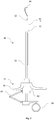
- Fig. 1 shows a lateral, schematic sectional illustration of a resectoscope 12 according to the invention, which has a conveyor 10 and an electrode instrument 42 that can be longitudinally displaced by means of the slide 62 of the conveyor 10.
- the electrode instrument 42 is the system component 13 of the conveyor 10, which is to be held detachably on the conveyor 10 by means of a latching system 18.
- the resectoscope 12 has a shaft 46 which comprises a shaft tube system 48, shown in dashed lines, which, in a manner not shown, consists of a jacket tube and an inner tube.
- An optics guide tube 50 runs inside the shaft tube system 48 and an optics 54 runs inside the optics guide tube 50.
- a working instrument 14, which is designed as an electrode instrument 42, runs between the optics guide tube 50 and the shaft tube system 48.
- a lighting means (not shown) runs inside or outside the optics guide tube 50, for example in the form of an optical fiber bundle.
- further elements, not shown here can run in the resectoscopes 12, such as, for example, a separate irrigation tube and the like.
- the shaft tube system 48 comprises openings, in a manner not shown here, through which the contaminated rinsing liquid can flow into the space between the jacket tube and the inner tube and flow away through the resectoscope shaft 46.
- the electrode instrument 42 is protected against displacements deviating from the longitudinal direction of the shaft 46, for example transversely to the longitudinal direction, by means of a guide element 52 which has a partially circular cross section.
- the guide element 52 is supported on the optics 54.
- the electrode instrument 42 is mounted on the optics guide tube 50 so as to be longitudinally displaceable and has an elongated shaft 16.
- the proximal end of the shaft 16 of the electrode instrument 42 is shown in FIG Fig. 1 Locked in a manner not shown in the interior of the slide 62 of the conveyor 10.
- the slide 62 can thus be viewed as a connecting body 15 in the embodiment shown.
- the electrode instrument 42 can be positively moved axially in the distal and proximal directions by actuating the handle parts 56, 58. It can be pushed out over the distal end of the optics guide tube 50 and the shaft tube system 48. This enables the surgeon to continue from the Resectoscope tip to manipulate removed tissue.
- the electrode instrument 42 has at its distal end an electrode 44 which is designed as a cutting loop and by means of which tissue can be removed by electrosurgical ablation. In this case, a high-frequency, electrical voltage is applied to the electrode 44 in order to cut up tissue.
- the resectoscope 10 shown has a passive transporter 10, in which the slide 62 is displaced in the distal direction against the distal, first handle part 56 by relative movement of the handle parts 56 and 58 arranged proximally of the resectoscope shaft 46 against a spring force applied by a spring bridge 60 .
- the electrode instrument 42 is supported by the in Fig. 1 Latching, not shown, in the latching system 18, forcibly displaced distally.
- the grip parts 58, 56 are relieved of pressure, the spring force generated by the spring bridge 60 forces the slide 62 back into its rest position, the electrode instrument 42 being pulled in the proximal direction.
- electrosurgical intervention with the electrode instrument 42 can be carried out without manual force on the part of the surgeon, that is to say passively.
- Fig. 2 shows a lateral, schematic sectional illustration of the in Fig. 1
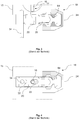
- FIGs. 3 and 4 show schematic sectional views of part of a conveyor 10 from the prior art, which includes a latching system 18 with a latching element 20, spring element 24 and a locking element 34.
- the prior art conveyor 10 mainly differs from that in FIG Fig. 5 illustrated conveyor 10 according to the invention that the latching element 20 of the in Figs. 3 and 4 shown conveyor 10 has no flushing channels.
- FIG. 4 FIG. 13 shows a schematic sectional view of the part from FIG Fig. 3 .
- the proximal end region of the shaft section 16 of a working instrument 14 is shown, which is shown in FIG Fig. 3 is shown above an engagement opening 22 and not yet is inserted into this and not yet locked in place.
- the end region has a diameter that is smaller than the diameter of the engagement opening 22.
- the engagement opening 22 is arranged in the shaft region of the latching element 20 and spans it completely, ie is designed in the form of a channel which is open on both sides.
- the engagement opening 22 and the end region of the shaft section 16 of the working instrument 14 can, as described elsewhere herein, have complementary latching lugs and latching grooves (not shown) and thereby form an additional latching connection.
- a locking lug of the locking system is always pressed onto the base of the locking groove by the spring element 24, i.e. a pressure is exerted on the shaft of the working instrument 14. This ensures the undercut within the locking system 18.
- the spring element 24, as seen from the direction of the longitudinal axis of the latching element 20, is arranged at one end of the latching element 20.
- the spring element 24 is designed as an elastic molded body and, in contrast to the latching element 20 and the locking element 34, is partially arranged outside of the conveyor 10.
- the part of the spring element 24 protruding laterally on the conveyor side wall can be used for manual actuation of the latching element 20, in particular for releasing a latching connection existing between the working instrument 14 and the latching system 18. If (manual) pressure is exerted on the spring element 24, the force is transmitted to the latching element 20 via an optional force transmission element 64 and the latching element 20 is displaced along its longitudinal axis in the interior of the conveyor 10. This releases the clamping and / or locking connection between the engagement opening 22 and the shaft section 16, so that the working instrument 14 can easily be removed from the resectoscope 12.
- the conveyor 10 also has a locking element 34, which is arranged in sections in a second engagement opening 22 and in sections in a channel not shown in detail in the connecting body 15.
- the locking element 34 is elongated and transversely to the longitudinal direction of the locking element 20 and parallel to the longitudinal direction of the conveyor 10 and the shaft 46 aligned.
- the engagement opening 22 provided for the locking element 34 is preferably designed as a substantially parallel channel to the engagement opening 22 provided for the working instrument 14. Furthermore, it is wider in the longitudinal direction of the latching element 20 than the diameter of the locking element 34 so as not to hinder the desired displacement of the latching element 20 in its longitudinal direction.
- the additional width ie the width that goes beyond the diameter of the locking element, preferably corresponds to the desired stroke of the latching element 20.
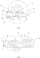
- Fig. 5 shows a schematic sectional view of the locking system 18 of a conveyor 10 according to the invention from the longitudinal direction of the conveyor 10, in which the flushing grooves 26 of the locking element 34 can be seen.
- the conveyor 10 according to the invention differs from that in Figs. 3 and 4 shown at least by the flushing grooves 26 shown here.
- Other features, such as the arrangement of the locking element 34 in an engagement opening 22 or the use of an elastic molded body as a spring element 24 can also be used in the conveyors 10 of the present invention.
- the flushing grooves 26 of the locking element 20 extend parallel to the longitudinal axis of the locking element 20 from one end of the locking element 20 to the other. This ensures a complete flow of rinsing liquid during cleaning.
- the flushing grooves 26 have a U-shaped cross section.
- the locking element 20 At its end lying outside the connecting body 15, the locking element 20 has a head section which has a larger diameter than the shaft section of the locking element 20 extending into the interior of the conveyor 10.
- the side of the head section facing the shaft section serves as a support surface for a spring element 24, which is designed as a metallic helical compression spring.
- the other end of the spring element 24 rests on a shoulder of the connecting body 15 and exerts an outward pressure.
- the locking system 18 is nevertheless held in the connecting body 15 of the conveyor 10 by the locking element 34.
- the locking element 34 is essentially like that in FIG Figs. 3 and 4 Locking element 34 shown is formed. However, it does not engage in a complementary engagement opening, but in a locking groove 36 which is formed in the outer wall of the latching element 20 and whose longitudinal axis is transverse to the longitudinal axis of the latching element 20.
- the locking groove 36 is wider than the diameter of the locking element 34, so that the desired displacement of the locking element 20 is not hindered.
- Fig. 6 shows a schematic sectional illustration of the latching system 18 of an alternative conveyor 10 according to the invention from the longitudinal direction of the conveyor 10.
- the latching element 20 comprises in a manner not shown here, as is the case in FIG Fig. 5 flushing grooves 26 shown, which are each suitable for forming a flushing channel 25 between the latching element 20 and the connecting body 15.
- the spring element 24 of the in Fig. 6 The conveyor 10 shown is arranged on the side of the latching element 20 opposite a unlocking element 66.
- the channel (cavity) provided in the connecting body 15 for the latching element 20 is not open on both sides of the connecting body 15, but closed on one side.
- the spring element 24 is arranged on the closed side of this channel and is supported on one side at the end of the channel and the other side on the latching element 20.
- the latching element 20 has grooves at this end which extend in the longitudinal direction of the Latching element 20 are formed circumferentially around its longitudinal axis.
- the unlocking element 66 is an actuating element (button) with the aid of which the locking connection between the working element 14 and the locking system 18 can be released.
- the unlocking element 66 is arranged on the side of the locking element 20 opposite the spring element 24, i.e. on the side of the channel provided for the locking element 20 in the connecting body 15 which is open to the outside.
- the engagement groove 23 is arranged in the outer wall (jacket surface) of the latching element 20.
- the longitudinal axis of the engagement groove 23 runs transversely to the longitudinal axis of the latching element 20.
- the locking element 34 has a head region which is accessible from outside the connecting body 15 and which has a wider diameter than the shaft section of the locking element 34 arranged inside the connecting body 15 and the locking groove 36.
Landscapes
- Health & Medical Sciences (AREA)
- Life Sciences & Earth Sciences (AREA)
- Surgery (AREA)
- Engineering & Computer Science (AREA)
- Nuclear Medicine, Radiotherapy & Molecular Imaging (AREA)
- Public Health (AREA)
- Veterinary Medicine (AREA)
- General Health & Medical Sciences (AREA)
- Animal Behavior & Ethology (AREA)
- Molecular Biology (AREA)
- Medical Informatics (AREA)
- Biomedical Technology (AREA)
- Heart & Thoracic Surgery (AREA)
- Physics & Mathematics (AREA)
- Radiology & Medical Imaging (AREA)
- Pathology (AREA)
- Biophysics (AREA)
- Optics & Photonics (AREA)
- Plasma & Fusion (AREA)
- Otolaryngology (AREA)
- Urology & Nephrology (AREA)
- Orthopedic Medicine & Surgery (AREA)
- Surgical Instruments (AREA)
Abstract
Description
- Die Erfindung betrifft einen Transporteur der im Oberbegriff des Anspruches 1 genannten Art.
- Transporteure der gattungsgemäßen Art werden in Resektoskopen vor allem in der Urologie bei chirurgischen Arbeiten in der Blase und der Urethra verwendet. Sie werden beispielsweise in Verbindung mit elektrochirurgischen Durchgangsinstrumenten zur Resektion und Vaporisation von Gewebe, zum Beispiel von Gewebe im unteren Harntrakt verwendet. Dazu umfassen die Resektoskope ein längsverschiebbares Elektrodeninstrument, das nach dem Einführen des Resektoskops mit seinem distalen Arbeitsende aus dem distalen Ende des Schaftrohres des Resektoskops hervorgeschoben werden kann.
- Das Elektrodeninstrument ist an seinem proximalen Ende mit dem Transporteur des Resektoskops verbunden, von dem es in Längsrichtung verschoben werden kann, um die Schneidbewegung auszuführen. Der Transporteur ist üblicherweise abnehmbar am proximalen Ende des Schaftrohres des Resektoskops befestigt.
- Der Transporteur weist einen längsverschiebbaren Schlitten auf, mit dem das Elektrodeninstrument zur gemeinsamen Längsbewegung koppelbar ist. Die Betätigung des Transporteurs erfolgt üblicherweise durch die Finger einer Hand, die einerseits am Schlitten und andererseits an den feststehenden Teilen des Transporteurs angreifen, die mit dem Führungsrohr fest verbunden sind. Dabei kann die Bewegung des Transporteurs beispielsweise gegen eine rückstellende Feder erfolgen, die als Schenkelfeder oder Blattfeder ausgebildet sein kann. Beispielhafte Instrumente sind in der
DE 10 2011 011 216 A1 ,US 2004/0242959 A1 ,US 6358200 undDE 35 00 527 A1 beschrieben. - Die Kopplung zwischen dem Transporteur und von ihm längsverschiebbaren Arbeitsinstrumenten, wie einem Elektrodeninstrument, oder anderen stationären Systemkomponenten, wie dem Schaft, erfolgt üblicherweise über Rastverbindungen. Wird beispielsweise das proximale Ende des Elektrodeninstruments mit dem entsprechenden Verbindungspartner in dem Transporteur in Kontakt gebracht, so erfolgt durch das Einführen des Elektrodeninstruments in der Regel eine automatische Einrastung des Instruments. Die Entrastung des Elektrodeninstruments muss dagegen üblicherweise manuell unterstützt werden.
- Die Verrastung des Elektrodeninstruments erfolgt derzeit durch einen Hinterschnitt eines länglichen Rastelements in einer dafür vorgesehenen Nut in dem Instrumentenschaft. Das Rastelement ist hierfür quer zur Längsrichtung des Arbeitsinstruments und des Resektoskopschaftes in dem Transporteur angeordnet. Durch eine Einführschräge am Rastelement erzeugt der Schaft des eingeführten Arbeitsinstruments eine Kraft, die das Rastelement entlang seiner eigenen Längsachse und quer zur Längsachse des Arbeitsinstruments verschiebt. Durch einen mittels eines Federelements ausgeübten Gegendruck wird das Rastelement anschließend in seine Ausgangsstellung zurückgedrückt und der Hinterschnitt in der Rastverbindung sichergestellt. Das in der Rastverbindung verwendete Federelement kann z. B. eine Druckfeder oder ein Elastomer-Formteil sein.
- Um auch ohne eingerastetes Arbeitsinstrument eine definierte Ruhelage des Rastelements zu gewährleisten und eine unerwünschte Demontage zu verhindern, umfasst die Rastverbindung üblicherweise ein fest verbautes Sperrelement, das in einer Durchbrechung des Rastelements verbaut ist und ein unerwünschtes Herausfallen des Rastsystems aus dem Transporteur verhindert.
- Die Entrastung des Arbeitsinstruments oder der anderen verrasteten Systemkomponenten erfolgt durch manuelle, d.h. händisch durch das Bedienpersonal durchgeführte, Verschiebung des Rastelements quer zur Längsachse des Transporteurs.
- Da das Rastelement bewegbar in einem Kanal innerhalb eines Verbindungskörpers des Transporteurs angeordnet ist, besteht rund um das Rastelement ein enger Spalt, der während der Reinigung und der Sterilisation nur schwer zu erreichen ist. Die Verschiebungen des Rastelements können ferner zu Verschmierungen von Verunreinigungen in diesem Spalt führen. Darüber hinaus ist der Kanal, in dem das Rastelement innerhalb des Verbindungskörpers angeordnet ist, häufig auf beiden Seiten des Transporteurs geschlossen. Auf der einen Seite wird der Kanal dabei durch eine Seitenwand des Transporteurs geschlossen, auf der anderen Seite durch das Federelement, zum Beispiel in Form eines Elastomer-Formteils, oder ein Betätigungselement. Dies erschwert die Reinigung zusätzlich und schafft weitere Hohlräume, die schwer zu reinigen sind. Auch in der für das Sperrelement vorgesehenen Durchbrechung des Rastelements können sich Verunreinigungen ansammeln. Die Verwendung eines Elastomer-Formteils als Federelement birgt zudem das Risiko, dass durch die entstehende Verformung bei der Betätigung des Rastelements Verunreinigungen in dem Federelement an Stellen eingeschlossen werden können, die schlecht oder gar nicht zu reinigen sind.
- Aufgabe der vorliegenden Erfindung ist es daher, einen Transporteur bereitzustellen, der leichter und zuverlässiger zu reinigen ist, insbesondere im Bereich des für die Verrastung von Arbeitsinstrumenten und anderen Systemkomponenten vorgesehenen Rastsystems.
- Gelöst wird diese Aufgabe durch einen Transporteur mit den Merkmalen von Anspruch 1 sowie durch ein Resektoskop mit den Merkmalen von Anspruch 14.
- Die Erfindung betrifft insbesondere in einem ersten Aspekt einen Transporteur für ein Resektoskop für die endoskopische Chirurgie, wobei der Transporteur einen Verbindungskörper und zur Verbindung mit einer Systemkomponente in dem Verbindungskörper ein Rastsystem aufweist, das ein langgestrecktes, vorzugsweise quer zur Längsachse des Transporteurs angeordnetes Rastelement mit einer Eingriffsöffnung oder einer Eingriffsnut und ein Federelement umfasst, dadurch gekennzeichnet, dass zwischen Rastelement und Verbindungskörper ein oder mehrere, parallel zur Längsachse des Rastelements angeordnete Spülkanäle ausgebildet sind.
- In einer bevorzugten Ausführungsform betrifft die Erfindung einen Transporteur für ein Resektoskop für die endoskopische Chirurgie, wobei der Transporteur zur Steuerung der Längsverschiebung eines Arbeitsinstruments, das einen langgestreckten Schaftabschnitt aufweist, ausgebildet ist und zur Verbindung mit dem proximalen Endbereich des Arbeitsinstruments ein Rastsystem aufweist, das ein langgestrecktes, quer zur Längsachse des Transporteurs angeordnetes Rastelement mit einer seitlichen Eingriffsöffnung und ein Federelement umfasst, dadurch gekennzeichnet, dass das Rastelement ein oder mehrere, parallel zur Längsachse des Rastelements angeordnete Spülnuten aufweist.
- In einem verwandten Aspekt betrifft die Erfindung ein Resektoskop zur Verwendung in der endoskopischen Chirurgie, dadurch gekennzeichnet, dass es einen erfindungsgemäßen Transporteur und vorzugsweise eine in dem Transporteur verrastete Systemkomponente umfasst, besonders bevorzugt ein Arbeitsinstrument.
- Durch die erfindungsgemäße Einlassung von Spülnuten in das Rastelement und/oder den Verbindungskörper werden in dem Transporteur von außen zugängliche Spülkanäle gebildet, welche die Reinigung und Sterilisation des Rastsystems erleichtern und verbessern. Alle Elemente des Rastsystems können während der Reinigung von Spülflüssigkeit umspült bzw. bei der Sterilisation von Sterilisationsgas erreicht werden. Die Gefahr einer andauernden Kontamination der Instrumente ist damit gegenüber dem Stand der Technik deutlich gesenkt.
- Das erfindungsgemäß modifizierte Rastsystem ist für Transporteure geeignet, die in der endoskopischen Chirurgie verwendet werden. Für diese Instrumente ist ein hoher Reinheitsgrad und Sterilität besonders wichtig. Die Transporteure sind in der Regel Teile eines Resektoskops, das darüber hinaus in üblicher Ausbildungsweise noch ein Schaftteil mit einem rohrartigen Schaft und eine durch den Transporteur in den Schaftteil einführbare langgestreckte Optik aufweist. Die Teile des Resektoskops können den Erfordernissen des jeweiligen Eingriffs angepasst werden und daher variieren.
- Neben Transporteur, Schaftteil und Optik können die Resektoskope weitere Teile aufweisen, beispielsweise ein Leuchtmittel, wie ein Lichtleitfaserbündel, und unterschiedliche Arbeitsinstrumente (Durchgangsinstrumente), die durch den Schaft des Resektoskops zur Eingriffsstelle geführt werden und dort beispielsweise zur Manipulation von Gewebe verwendet werden können.
- Der Transporteur weist einen Verbindungskörper auf, in dem das erfindungsgemäße Rastsystem angeordnet ist. Der Verbindungskörper grenzt somit unmittelbar an das Rastsystem an, insbesondere an das Rastelement des Rastsystem aber auch an die übrigen Komponenten des Rastsystems. Soll der Transporteur zur Längsverschiebung der verrasteten Systemkomponente ausgebildet sein, so kann der Verbindungskörper beispielsweise der Schlitten des Transporteurs sein, oder ein Teil des Schlittens.
- Der Transporteur ist mittels des Rastsystems zur Verbindung mit einer Systemkomponente ausgebildet. Vorzugsweise ist insbesondere der Verbindungskörper des Transporteurs zur Verbindung mit einer Systemkomponente ausgebildet. Dies bedeutet, dass die Systemkomponente mittels des Rastsystems in dem Transporteur, insbesondere dessen Verbindungskörper, lösbar gehalten werden kann.
- Das Rastsystem ist zur Verrastung unterschiedlicher Teile geeignet. Die Systemkomponente kann somit jegliche Komponente (Teil) eines Resektoskops sein, die lösbar mit dem Transporteur, insbesondere dessen Verbindungskörper, verbunden werden soll. Dabei ist die Systemkomponente kein Teil des Transporteurs. Die Systemkomponente kann beispielsweise ausgewählt sein aus der Gruppe bestehend aus Arbeitsinstrument (Durchgangsinstrument), Optik, Schaftrohrsystem (z.B. Hüllrohr und/oder Innenrohr) und anderen. In einer bevorzugten Ausführungsform ist die Systemkomponente ein Arbeitsinstrument. In einer anderen Ausführungsform ist die Systemkomponente eine Optik.
- Es versteht sich entsprechend, dass der erfindungsgemäße Transporteur nicht nur ein hierin beschriebenes Rastsystem umfassen kann, sondern auch mehrere, wobei die verschiedenen Rastsysteme jeweils zur Verrastung unterschiedlicher Systemkomponenten ausgebildet und angeordnet sind. Der Transporteur kann beispielsweise ein, zwei, drei oder mehr der hierin beschriebenen Rastsysteme umfasst, vorzugsweise zwei oder mehr.
- Wie erwähnt ist die verrastbare Systemkomponente vorzugsweise ein Arbeitsinstrument. Diese sind in der Regel längsverschiebbar in einem Resektoskop angeordnet, um dem medizinischen Fachpersonal einen flexiblen Eingriff an der Eingriffsstelle zu ermöglichen. Der Transporteur kann entsprechend zur Steuerung der Längsverschiebung eines Arbeitsinstruments ausgebildet sein. Geeignete Arbeitsinstrumente, die für einen Eingriff in der endoskopischen Chirurgie verwendet werden können, sind Fachleuten bekannt. Das Arbeitsinstrument kann beispielsweise ein Elektrodeninstrument oder ein Steinfanginstrument sein, wobei das hierin beschriebene Arbeitsinstrument bevorzugt ein Elektrodeninstrument ist.
- Das Elektrodeninstrument weist einen langgestreckten Schaftabschnitt (Schaftteil) auf und ist als Durchgangsinstrument für ein Resektoskop ausgebildet, d.h. als Instrument, das durch ein resektoskopisches Schaftrohr in eine Körperöffnung einführbar ist. Das Elektrodeninstrument weist an seinem distalen Ende eine mit Hochfrequenzstrom beaufschlagbare Elektrode auf. Bei der Elektrode kann es sich um eine Schneidschlinge, einen Vaporisationsknopf (PlasmaButton) oder andere handelsübliche Elektroden handeln. Bevorzugt ist die Elektrode eine Schneidschlingenelektrode. Entsprechende Elektroden und Elektrodeninstrumente sind Fachleuten bekannt.
- Das Elektrodeninstrument kann ein bipolares Elektrodeninstrument sein, das die Elektrode als Teil einer Elektrodenanordnung umfasst. In diesem Falle wird das Elektrodeninstrument zum Beispiel eine zweite Elektrode im distalen Endbereich des Elektrodeninstruments umfassen, die als Neutralelektrode ausgebildet ist. Alternativ kann die zweite Elektrode (Neutralelektrode) auch an anderen Elementen des distalen Endbereichs des Resektoskops angeordnet sein. Selbstverständlich kann das Elektrodeninstrument auch als monopolares Instrument ausgebildet sein.
- Die Systemkomponente kann einen langgstreckten Schaftabschnitt aufweisen. Vorzugsweise ist die Längsachse der Systemkomponente parallel zur Längsachse des Resektoskopsschaftes bzw. des Transporteurs. Der proximale Endbereich der Systemkomponente kann mit dem Rastsystem verbunden sein. Es ist aber auch denkbar, eine laterale Seite der Systemkoponente mit einer am bzw. im Verbindungskörper seitlich angeordneten Eingriffsöffnung bzw. Eingriffsnut zu verbinden, d.h. zu verrasten. Bevorzugt ist aber das Rastsystem zur Verbindung mit dem proximalen Endbereich der Systemkomponente ausgebildet. In dieser Ausführungsform ist der proximale Endbereich der Systemkomponente in die Eingriffsöffnung bzw. Eingriffsnut des Rastsystems einführbar.
- Ist die Systemkomponente ein Arbeitsinstrument, so kann das Arbeitsinstrument innerhalb des Schaftes des Resektoskops durch den Transporteur längsverschiebbar sein, d. h. in axialer Richtung nach distal und proximal beweglich. Zum Anschluss an das Resektoskop weist das Arbeitsinstrument den langgestreckten Schaftabschnitt auf, der zur Herstellung einer bewegungsgekoppelten Verbindung an seinem proximalen Endbereich an einem von dem Transporteur umfassten Schlitten verrastbar ist. Der Schlitten gleitet typischerweise auf einem Rohr und wird über eine Federeinheit federvorgespannt in einer Ruhestellung gehalten. So kann die Arbeitseinheit, z. B. die Elektrode, am distalen Ende auf zu schneidendes Gewebe zu- oder von diesem wegbewegt werden, ohne das gesamte Resektoskop bewegen zu müssen. Darüber hinaus ist es durch die Längsverschiebbarkeit des Arbeitsinstruments beispielsweise möglich, zwischen einer distalen Elektrode und dem Isoliereinsatz Gewebe einzuklemmen und von der Eingriffsstelle zu entfernen.
- Der proximale Endbereich des Schaftabschnitts des Arbeitsinstruments ist mittels eines Rastsystems mit dem Transporteur verbunden. Das Rastsystem ist Teil des Transporteurs und vorzugsweise innerhalb des Schlittens des Transporteurs angeordnet. Auf diese Weise kann das Arbeitsinstrument nach dem Verrasten des Instruments innerhalb des Schlittens mit diesem zusammen bewegt werden.
- Das Rastsystem der erfindungsgemäßen Transporteure umfasst stets ein Rastelement und ein Federelement und kann darüber hinaus optional ein Sperrelement umfassen. Das Rastsystem ist innerhalb des und an dem Transporteur so angeordnet, dass das Rastelement und optional das Sperrelement zum größten Teil, d.h. zu etwa 50% oder mehr innerhalb des Transporteurs angeordnet sind. Dazu weist der Transporteur eine entsprechende kanalförmige Aushöhlung (Kanal) auf. Diese ist mindestens auf einer Seite des Transporteurs offen, vorzugsweise auf beiden Seiten. Die Aushöhlung ist in etwa form- und größenkomplementär zu dem Rastsystem. Wie oben beschrieben, bestehen allerdings in den Randbereichen des Rastelements, des Federelements und des Sperrelements durchaus freie Spalte, die im Rahmen der Fertigung entstehen und/oder zur Gewährleistung einer freien Dreh- und Verschiebbarkeit oder anderer Funktionen des Rastsystems notwendig sind.
- Das Rastelement ist langgestreckt und quer zur Längsachse des Transporteurs angeordnet. Das Rastelement kann einen Schaftteil aufweisen und an einem Ende einen Kopfteil, der einen größeren Durchmesser aufweist als der Schaftteil. Dieser Kopfteil kann beispielsweise zur Abstützung des Federelements dienen. Schaft- und Kopfteil weisen vorzugsweise einen im Wesentlichen runden Querschnitt, ggfs. mit Ausnehmungen für die Spülnuten, auf. Das Rastelement kann somit, mit anderen Worten, in seinem Schaftteil eine im Wesentlichen zylindrische Form, ggfs. mit Ausnehmungen für die Spülnuten und die Sperrnut aufweisen.
- Das Rastelement weist in seiner Mantelfläche, d.h. im Verhältnis zu seiner Längsachse seitlich (lateral), eine oder mehrere seitliche Eingriffsöffnungen und/oder eine oder mehrere seitliche Eingriffsnuten auf. Eine der Eingriffsöffnungen oder eine der Eingriffsnuten ist für die Einführung des eines Teils der Systemkomponente, vorzugsweise des proximalen Endbereichs des Arbeitsinstruments, angeordnet und geeignet.
- Die Eingriffsöffnung kann kanalartig ausgebildet sein und einen im Wesentlichen zylindrischen Innenraum aufweisen. Die Eingriffsöffnung kann den Schaftteil des Rastelements kanalartig durchspannen. Die Eingriffsöffnung kann somit an beiden Seiten des Rastelements eine Öffnung erzeugen. Alternativ kann die Eingriffsöffnung an der dem Arbeitsinstrument gegenüberliegenden Seite geschlossen sein.
- Die Eingriffsnut kann einen U- oder teilkreisförmigen Querschnitt aufweisen und den Schaftteil des Rastelements durchspannen. Die Nut ist vorzugsweise an beiden Enden entlang ihrer Längsrichtung offen, d.h. von einem Gas oder einer Flüssigkeit durchströmbar.
- Die Eingriffsöffnung bzw. die Eingriffsnut sind quer zur Längsachse des Rastelements angeordnet.
- Das Rastelement kann weitere Eingriffsöffnungen aufweisen, beispielsweise für den Eingriff eines Sperrelements. Erfindungsgemäß ist es jedoch bevorzugt, dass ein Sperrelement in einer Sperrnut in der Außenwand des Rastelements angeordnet ist, wie an anderer Stelle hierin beschrieben.
- Um das Einführen und automatische Einrasten der Systemkomponente, vorzugsweise des Arbeitsinstruments, in das Rastelement zu ermöglichen, kann die Eingriffsöffnung bzw. die Eingriffsnut einen teilweise trichterförmigen Eingangsbereich aufweisen, d.h. einen einseitig schrägen Eingangsbereich. In diesem Eingangsbereich ist die Eingriffsöffnung bzw. die Eingriffsnut verbreitert ausgebildet. An einer Schräge des Eingangsbereichs kann das proximale Ende des Arbeitsinstruments während des Einführens entlang gleiten und dabei das Rastelement derart seitlich, d.h. quer zur Längsachse des Transporteurs verschieben, dass das als Druckfeder ausgebildete Federelement komprimiert wird.
- Die für die Systemkomponente, vorzugsweise den proximalen Endbereich des Arbeitsinstruments, vorgesehene Eingriffsöffnung oder Eingriffsnut kann darüber hinaus ein oder mehrere Rastelemente oder Nuten umfassen, die mit einem Rastelement oder einer Nut am Arbeitsinstrument eine Rastverbindung eingehen. Auf diese Weise kann ein geeigneter Hinterschnitt in der Rastverbindung sichergestellt werden.
- Zwischen Rastelement und Verbindungskörper sind erfindungsgemäß ein oder mehrere, parallel zur Längsachse des Rastelements angeordnete Spülkanäle ausgebildet. Die Spülkanäle können entweder durch die Ausbildung von Spülnuten in der Außenwand des Rastelements oder durch Ausbildung von Spülnuten in der an das Rastelement angrenzenden Innenfläche des Verbindungskörpers ausgebildet werden. Auch eine Kombination von Spülnuten an den beiden Teilen ist denkbar und im Rahmen der Erfindung möglich. Somit weist in einer Ausführungsform das Rastelement ein oder mehrere, parallel zur Längsachse des Rastelements angeordnete Spülnuten auf. Alternativ oder zusätzlich kann der Verbindungskörper ein oder mehrere, parallel zur Längsachse des Rastelements und, vorzugsweise, angrenzend an das Rastelement angeordnete Spülnuten aufweisen. Es ist im Rahmen der Erfindung auch denkbar, in beiden Teilen Spülnuten derart auszubilden, dass jeweils eine Spülnut des Rastelements an eine Spülnut des Verbindungskörpers angrenzt.
- Die Spülnuten können jeweils einen teilkreisförmigen, z. B. einen halbkreisförmigen, oder einen U-förmigen Querschnitt aufweisen. Die Spülnuten sind dazu geeignet, einen Flüssigkeitskanal zu erzeugen, über den zwischen dem Rastelement und den übrigen Teilen des Transporteurs entstehende Spalten mit Spülflüssigkeit ausgespült werden können. Dazu sind die Spülnuten zur Ein- bzw. Ausleitung von Spülflüssigkeit vorzugsweise an beiden Enden des langgestreckten Rastelements bzw. des angrenzenden Verbindungskörpers offen. Die beiden Enden des Rastelements sind die entlang der Längsachse des Rastelements liegenden Enden. Innerhalb des Transporteurs sind diese Enden zu den Seiten des Transporteurs hin orientiert (lateral). Durch die Spülnuten ist entsprechend Spülflüssigkeit und/oder Gas (Sterilisationsgas) von einer lateralen Seite des Transporteurs auf die kontralaterale Seite des Transporteurs leitbar.
- Das Rastelement bzw. der Verbindungskörper kann eine oder mehrere Spülnuten aufweisen, d.h. beispielsweise eine, zwei, drei, vier oder mehr Spülnuten. In einer bevorzugten Ausführungsform weist das Rastelement bzw. der Verbindungskörper, vorzugsweise das Rastelement, vier Spülnuten auf. Die Spülnuten können um die Längsachse des Rastelements herum auf seinem Umfang bzw. auf dem Innenumfang der Aushöhlung des Verbindungskörpers verteilt sein. Dabei sind alle Spülnuten bevorzugt äquidistant voneinander beabstandet. So können in einem Rastelement bzw. Verbindungskörper mit vier Spülnuten die Nuten beispielsweise bei 0°, 90°, 180° und 270° auf dessen Umfang bzw. Innenumfang der Aushöhlung angeordnet sein. Bevorzugt sind jeweils einander gegenüberliegende Paare von Spülnuten auf dem Rastelement bz.w dem Innenumfang der Aushöhlung angeordnet.
- Das Rastsystem kann ferner ein langgestrecktes Sperrelement umfassen, das quer zur Längsachse des Rastelements in einer Sperrnut in der Außenwand des Rastelements angeordnet ist. Das Sperrelement verhindert in Abwesenheit des Arbeitsinstruments ein Herausfallen des Rastsystems aus dem Transporteur. Das Sperreleement weist einen langgestreckten Schaft auf, dessen eines Ende - vorzugsweise das proximale Ende - zumindest teilweise in einer Öffnung des Transporteurs bzw. des Schlittens angeordnet ist, die nicht Teil des Rastelements ist. Dieses Ende ist mit anderen Worten in einem das Rastsystem umschließenden Körper des Transporteurs angeordnet. Das andere Ende des Sperrelements - vorzugsweise das distale Ende - ist in einer Sperrnut des Rastelements angeordnet. Ein Teil des Sperrelements liegt somit in Abwesenheit des Arbeitsinstruments an einer Seitenfläche der Sperrnut an und verhindert so eine weitere Bewegung des Rastelements in Richtung der von dem Federelement ausgeübten Federkraft. Das Sperrelement kann ein von außerhalb des Verbindungskörpers zugängliches Kopfteil mit einem breiteren Durchmesser umfassen.
- Die Sperrnut ist seitlich in dem Schaftteil des Rasteleements angeordnet. Dabei ist die Sperrnut vorzugsweise in dem Endbereich des Rastelements lokalisiert, der nicht an das Federelement angrenzt. Die Sperrnut kann einen teilkreisförmigen Querschnitt aufweisen. Sie grenzt bevorzugt an eine oder mehrere Spülnuten an und bildet mit der oder den Spülnuten einen Spülkanal. Diese durch die Spülnuten und, optional, die Sperrnut erzeugten Spülkanäle erstrecken sich vorzugsweise über die gesamte Länge des Rastelements.
- Die Sperrnut ist mindestens abschnittsweise form- und größenkomplementär zu dem Sperrelement ausgebildet und angeordnet. Dabei weist die Sperrnut jedoch in Längsrichtung des Rastelements einen größeren Durchmesser auf, als das Sperrelement breit ist, um eine gewünschte Verschiebbarkeit des Rastelements in Längsrichtung des Rastelements zu gewährleisten.
- Das Rastsystem umfasst ferner ein Federelement. Das Federelement übt eine Federkraft in Richtung einer Außenseite, beispielsweise der einem Sperrelement abgewandten Außenseite, des Transporteurs aus. Wenn der Schaft des Arbeitsinstruments in die Eingriffsöffnung eingeführt ist, wird hierdurch zum Sicherstellen des Hinterschnitts ein Druck auf den Schaft ausgeübt (Klemmwirkung). Das Federelement ist vorzugsweise eine Druckfeder, beispielsweise eine Schraubendruckfeder oder ein elastisches Formteil. In bevorzugten Ausführungsformen ist das Federelement eine Schraubendruckfeder. Da diese keine zusätzlichen Hohlräume in dem Rastsystem erzeugt, ist das so erhaltene Rastsystem leichter und zuverlässiger zu reinigen. Es ist besonders bevorzugt, dass das Federelement, insbesondere die Schraubendruckfeder, aus Metall ist. Geeignete Federelemente sind Fachleuten bekannt.
- In den Zeichnungen sind Ausführungsbeispiele der Erfindung schematisch dargestellt. Es zeigen:
- Fig. 1
- eine seitliche, schematische Schnittdarstellung eines erfindungsgemäßen Resektoskops, das einen Transporteur und ein mittels des Schlittens des Transporteurs längsverschiebbares Elektrodeninstrument aufweist;
- Fig. 2
- eine seitliche, schematische Schnittdarstellung eines erfindungsgemäßen Transporteurs mit einem mittels des Schlittens des Transporteurs längsverschiebbares Elektrodeninstrument;
- Fig. 3
- eine schematische Schnittdarstellung eines Teils eines Transporteurs aus dem Stand der Technik, der ein Rastsystem mit einem Rastelement, Federelement und einem Sperrelement, wobei das Rastelement keine Spülkanäle aufweist;
- Fig. 4
- eine um 90° gedrehte schematische Schnittdarstellung des Teils aus
Fig. 3 ; - Fig. 5
- eine schematische Schnittdarstellung des Rastsystems eines erfindungsgemäßen Transporteurs aus Längsrichtung des Transporteurs, in der die Spülnuten des Sperrelements erkennbar sind; und
- Fig. 6
- eine schematische Schnittdarstellung des Rastsystems eines alternativen, erfindungsgemäßen Transporteurs aus Längsrichtung des Transporteurs.
- Weitere Vorteile, Kennzeichen und Merkmale der vorliegenden Erfindung werden bei der nachfolgenden detaillierten Beschreibung von Ausführungsbeispielen anhand der beigefügten Zeichnungen deutlich. Allerdings ist die Erfindung nicht auf diese Ausführungsbeispiele beschränkt.
-
Fig. 1 zeigt eine seitliche, schematische Schnittdarstellung eines erfindungsgemäßen Resektoskops 12, das einen Transporteur 10 und ein mittels des Schlittens 62 des Transporteurs 10 längsverschiebbares Elektrodeninstrument 42 aufweist. Das Elektrodeninstrument 42 ist die Systemkomponente 13 des Transporteurs 10, die mittels eines Rastsystems 18 an dem Transporteur 10 lösbar gehalten werden soll. - Das Resektoskop 12 weist einen Schaft 46 auf, der ein gestrichelt dargestelltes Schaftrohrsystem 48 umfasst, das in nicht dargestellter Weise aus einem Hüllrohr und einem Innenrohr besteht. Innerhalb des Schaftrohrsystems 48 verläuft ein Optikführungsrohr 50 und innerhalb des Optikführungsrohrs 50 eine Optik 54. Zwischen Optikführungsrohr 50 und Schaftrohrsystem 48 verläuft ein Arbeitsinstrument 14, das als Elektrodeninstrument 42 ausbildet ist. Darüber hinaus verläuft im Inneren oder außerhalb des Optikführungsrohres 50 ein nicht dargestelltes Beleuchtungsmittel, zum Beispiel in Form eines Lichtleitfaserbündels. Darüber hinaus können weitere hier nicht dargestellte Elemente in den Resektoskopen 12 verlaufen, wie beispielsweise ein separates Spülrohr und dergleichen. Das Schaftrohrsystem 48 umfasst in seinem distalen Endbereich in hier nicht dargestellter Weise Öffnungen durch die verunreinigte Spülflüssigkeit in den Zwischenraum zwischen Hüllrohr und Innenrohr einströmen und durch den Resektoskopschaft 46 abfließen kann.
- Das Elektrodeninstrument 42 ist mittels eines Führungselements 52, das einen teilkreisförmigen Querschnitt aufweist, gegen Verschiebungen abweichend von der Längsrichtung des Schaftes 46, zum Beispiel quer zur Längsrichtung, geschützt. Das Führungselement 52 stützt sich an der Optik 54 ab. Das Elektrodeninstrument 42 ist längsverschiebbar an dem Optikführungsrohr 50 gelagert und weist einen langgestreckten Schaft 16 auf.
- Das proximale Ende des Schaftes 16 des Elektrodeninstruments 42 ist in
Fig. 1 nicht dargestellter Weise im Inneren des Schlittens 62 des Transporteurs 10 verrastet. Der Schlitten 62 kann somit in der gezeigten Ausführungsform als Verbindungskörper 15 angesehen werden. Das Elektrodeninstrument 42 kann durch Betätigung der Griffteile 56, 58 zwangsgeführt axial in distale und proximale Richtung bewegt werden. Dabei kann es über das distale Ende des Optikführungsrohrs 50 und des Schaftrohrsystems 48 hinausgeschoben werden. So wird es dem Operateur ermöglicht, auch weiter von der Resektoskopspitze entferntes Gewebe zu manipulieren. Das Elektrodeninstrument 42 weist an seinem distalen Ende eine Elektrode 44 auf, die als Schneidschlinge ausgebildet ist und mittels derer Gewebe durch elektrochirurgische Ablation entfernt werden kann. Hierbei wird an die Elektrode 44 eine hochfrequente, elektrische Spannung angelegt, um Gewebe zu zerschneiden. - Das dargestellte Resektoskop 10 weist einen passiven Transporteur 10 auf, bei dem der Schlitten 62 durch Relativbewegung der proximal von dem Resektoskopschaft 46 angeordneten Griffteile 56 und 58 zueinander gegen eine von einer Federbrücke 60 aufgebrachte Federkraft in distale Richtung gegen das distale, erste Griffteil 56 verschoben wird. Bei der Verschiebung des Schlittens 62 in distale Richtung gegen das Griffteil 56 wird das Elektrodeninstrument 42 durch die in
Fig. 1 nicht dargestellte Verrastung in dem Rastsystem 18 zwangsgeführt nach distal verschoben. Bei einer Entlastung der Griffteile 58, 56 zwingt die von der Federbrücke 60 erzeugte Federkraft den Schlitten 62 zurück in seine Ruheposition, wobei das Elektrodeninstrument 42 in proximale Richtung gezogen wird. Bei der Rückverschiebung des Schlittens 62 kann ohne Handkraft des Operateurs, also passiv, ein elektrochirurgischer Eingriff mit dem Elektrodeninstrument 42 vorgenommen werden. -
Fig. 2 zeigt eine seitliche, schematische Schnittdarstellung des inFig. 1 abgebildeten erfindungsgemäßen Transporteurs 10 mit dem mittels des Schlittens 62 des Transporteurs 10 längsverschiebbaren Elektrodeninstrument 42 und dem Optikführungsrohr 50, aber ohne das Schaftrohrsystem 48 des Resektoskops 12 und ohne die Optik 54. Es ist erkennbar, dass das Elektrodeninstrument 42 mit dem proximalen Endbereich seines Schaftabschnitts 16 in den Schlitten 62 des Transporteurs 10 eingeführt ist und von diesem gehalten wird. -
Fig. 3 und 4 zeigen schematische Schnittdarstellungen eines Teils eines Transporteurs 10 aus dem Stand der Technik, der ein Rastsystem 18 mit einem Rastelement 20, Federelement 24 und einem Sperrelement 34 umfasst. Der Transporteur 10 aus dem Stand der Technik unterscheidet sich hauptsächlich dadurch von dem inFig. 5 abgebildeten erfindungsgemäßen Transporteur 10, dass das Rastelement 20 des inFig. 3 und 4 gezeigten Transporteurs 10 keine Spülkanäle aufweist.Fig. 4 zeigt eine um 90° gedrehte schematische Schnittdarstellung des Teils ausFig. 3 . - Es ist der proximale Endbereich des Schaftabschnitts 16 eines Arbeitsinstruments 14 gezeigt, der in der
Fig. 3 oberhalb einer Eingriffsöffnung 22 dargestellt ist und noch nicht in diese eingeführt und darin noch nicht verrastet ist. Der Endbereich weist einen Durchmesser auf, der kleiner ist als der Durchmesser der Eingriffsöffnung 22. Die Eingriffsöffnung 22 ist in dem Schaftbereich des Rastelements 20 angeordnet und durchspannt dieses vollständig, d.h. ist in Form eines Kanals ausgebildet, der an beiden Seiten offen ist. Durch Einführen des Schaftabschnitts 16 in den Halbtrichter-förmigen Endbereich der Eingriffsöffnung 22 wird das Rastelement 20 entlang seiner Längsachse in Richtung des Sperrelements 34 bzw. in Richtung des Trichteranfangs verschoben (in derFig. 3 nach links). - Die Eingriffsöffnung 22 und der Endbereich des Schaftabschnitts 16 des Arbeitsinstruments 14 können, wie an anderer Stelle hierin beschrieben, nicht dargestellte, komplementäre Rastnasen und Rastnuten aufweisen und hierdurch eine zusätzliche Rastverbindung bilden. Darüber hinaus wird durch das Federelement 24 eine Rastnase des Rastsystems stets auf den Grund der Rastnut gedrückt, d.h. ein Druck auf den Schaft des Arbeitsinstruments 14 ausgeübt. Hierdurch wird der Hinterschnitt innerhalb des Rastsystems 18 sichergestellt. Das Federelement 24 ist, aus Richtung der Längsachse des Rastelements 20 gesehen, an einem Ende des Rastelements 20 angeordnet. Das Federelement 24 ist als elastischer Formkörper ausgebildet und, im Gegensatz zu dem Rasteelement 20 und dem Sperrelement 34 teilweise außerhalb des Transporteurs 10 angeordnet. Der lateral an der Transporteurseitenwand heraustretende Teil des Federelements 24 kann zur manuellen Betätigung des Rastelements 20 verwendet werden, insbesondere zum Lösen einer zwischen dem Arbeitsinstrument 14 und dem Rastsystem 18 bestehenden Rastverbindung. Wird ein (manueller) Druck auf das Federelement 24 ausgeübt, so wird die Kraft über ein optionales Kraftübertragungselement 64 auf das Rastelement 20 übertragen und das Rastelement 20 entlang seiner Längsachse in dem Inneren des Transporteurs 10 verschoben. Hierdurch wird die klemmende und/oder rastende Verbindung zwischen Eingriffsöffnung 22 und Schaftabschnitt 16 gelöst, sodass das Arbeitsinstrument 14 leicht aus dem Resektoskop 12 entnommen werden kann.
- Der Transporteur 10 weist ferner ein Sperrelement 34 auf, das abschnittsweise in einer zweiten Eingriffsöffnung 22 angeordnet ist und abschnittsweise in einem nicht detailliert dargestellten Kanal in dem Verbindungskörper 15. Hierdurch wird das Rastelement 20 auch dann in dem Transporteur 10 gehalten und vor einem Herausfallen geschützt, wenn kein Arbeitsinstrument 14 in der ersten Eingriffsöffnung 22 angeordnet ist. Das Sperrelement 34 ist langgestreckt ausgebildet und quer zur Längsrichtung des Rastelements 20 und parallel zur Längsrichtung des Transporteurs 10 und des Schaftes 46 ausgerichtet. Die für das Sperrelement 34 vorgesehene Eingriffsöffnung 22 ist vorzugsweise als im Wesentlichen paralleler Kanal zu der für das Arbeitsinstrument 14 vorgesehenen Eingriffsöffnung 22 ausgebildet. Ferner ist sie in Längsrichtung des Rastelements 20 breiter als der Durchmesser des Sperrelements 34 um das gewünschte Verschieben des Rastelements 20 in seiner Längsrichtung nicht zu behindern. Vorzugsweise entspricht die zusätzliche Breite, d.h. die Breite die über den Durchmesser des Sperrelements hinausgeht, dem gewünschten Hub des Rastelements 20.
-
Fig. 5 zeigt eine schematische Schnittdarstellung des Rastsystems 18 eines erfindungsgemäßen Transporteurs 10 aus Längsrichtung des Transporteurs 10, in der die Spülnuten 26 des Sperrelements 34 erkennbar sind. Der erfindungsgemäße Transporteur 10 unterscheidet sich von dem inFig. 3 und 4 gezeigten mindestens durch die hier gezeigten Spülnuten 26. Andere Merkmale, wie die Anordnung des Sperrelements 34 in einer Eingriffsöffnung 22 oder die Verwendung eines elastischen Formkörpers als Federelement 24 können auch in den Transporteuren 10 der vorliegenden Erfindung Anwendung finden. - Die Spülnuten 26 des Rastelements 20 erstrecken sich parallel zur Längsachse des Rastelements 20 von dem einen Ende des Rastelements 20 zum anderen. Hierdurch wird ein vollständiger Durchfluss von Spülflüssigkeit bei der Reinigung gewährleistet. Die Spülnuten 26 weisen einen U-förmigen Querschnitt auf.
- An seinem außerhalb des Verbindungskörpers 15 liegenden Ende weist das Rastelement 20 einen Kopfabschnitt auf, der einen größeren Durchmesser hat, als der sich in das Innere des Transporteurs 10 erstreckende Schaftabschnitt des Rastelements 20. Die dem Schaftabschnitt zugewandte Seite des Kopfabschnitts dient als Auflagefläche für ein Federelement 24, das als metallische Schraubendruckfeder ausgebildet ist. Das Federelement 24 liegt mit seinem anderen Ende auf einem Absatz des Verbindungskörpers 15 auf und übt einen Druck nach außen aus.
- Durch das Sperrelement 34 wird das Rastsystem 18 dennoch in dem Verbindungskörper 15 des Transporteurs 10 gehalten. Das Sperrelement 34 ist im Wesentlichen wie das in
Fig. 3 und 4 dargestellte Sperrelement 34 ausgebildet. Es greift jedoch nicht in eine komplementäre Eingriffsöffnung ein, sondern in eine Sperrnut 36, die in der Außenwand des Rastelements 20 ausgebildet ist und deren Längsachse quer zur Längsachse des Rastelements 20 ist. Die Sperrnut 36 ist breiter als der Durchmesser des Sperrelements 34, sodass das gewünschte Verschieben des Rastelements 20 nicht behindert wird. -
Fig. 6 zeigt eine schematische Schnittdarstellung des Rastsystems 18 eines alternativen, erfindungsgemäßen Transporteurs 10 aus Längsrichtung des Transporteurs 10. Das Rastelement 20 umfasst in hier nicht dargestellter Weise, wie das inFig. 5 gezeigte, Spülnuten 26, die jeweils geeignet sind, einen Spülkanal 25 zwischen dem Rastelement 20 und dem Verbindungskörper 15 auszubilden. - Im Gegensatz zu dem Transporteur 10 gemäß
Fig. 5 ist das Federelement 24 des inFig. 6 gezeigten Transporteurs 10 auf der einem Entrastungselement 66 entgegengesetzten Seite des Rastelements 20 angeordnet. Der in dem Verbindungskörper 15 für das Rastelement 20 vorgesehene Kanal (Aushöhlung) ist nicht an beiden Seiten des Verbindungskörpers 15 offen, sondern einseitig geschlossen. Das Federelement 24 ist an der geschlossenen Seite dieses Kanals angeordnet und stützt sich einseitig an dem Ende des Kanals ab und mit der anderen Seite an dem Rastelement 20. Zur Abstützung des Federelements 24 weist das Rastelement 20 an diesem Ende Nuten auf, die in Längsrichtung des Rastelements 20 umlaufend um dessen Längsachse ausgebildet sind. - Das Entrastungselement 66 ist ein Betätigungselement (Knopf) mit dessen Hilfe die Rastverbindung zwischen Arbeitselement 14 und dem Rastsystem 18 gelöst werden kann. Dazu ist das Entrastungselement 66 an der dem Federelement 24 gegenüberliegenden Seite des Rastelements 20 angeordnet, d.h. an der Seite des für das Rastelement 20 im Verbindungskörper 15 vorgesehenen Kanals, die nach außen offen ist.
- Darüber hinaus unterscheidet sich das in
Fig. 6 dargestellte Rastsystem 18 auch dadurch von dem in derFig. 5 dargestellten, dass der proximale Endbereich des Arbeitselements 14 nicht in einer Eingriffsöffnung 22 des Rastelements 20 sondern in einer Eingriffsnut 23 angeordnet ist. Die Eingriffsnut 23 ist in der Außenwand (Mantelfläche) des Rastelements 20 angeordnet. Die Längsachse der Eingriffsnut 23 verläuft quer zur Längsachse des Rastelements 20. - Das Sperrelement 34 weist einen von außerhalb des Verbindungskörpers 15 zugänglichen Kopfbereich auf, der einen breiteren Durchmesser aufweist, als der innerhalb des Verbindungskörpers 15 und der Sperrnut 36 angeordnete Schaftabschnitt des Sperrelements 34.
- Obwohl die vorliegende Erfindung anhand der Ausführungsbeispiele detailliert beschrieben worden ist, ist für den Fachmann selbstverständlich, dass die Erfindung nicht auf diese Ausführungsbeispiele beschränkt ist, sondern dass vielmehr Abwandlungen in der Weise möglich sind, dass einzelne Merkmale weggelassen oder andersartige Kombinationen der vorgestellten Einzelmerkmale verwirklicht werden können, sofern der Schutzbereich der beigefügten Ansprüche nicht verlassen wird. Die vorliegende Offenbarung schließt sämtliche Kombinationen der vorgestellten Einzelmerkmale ein.
Bezugszeichenliste 10 Transporteur 48 Schaftrohrsystem 12 Resektoskop 50 Optikführungsrohr 13 System komponente 52 Führungselement 14 Arbeitsinstrument 54 Optik 15 Verbindungskörper 56 Griffteil 16 Schaftabschnitt 58 Griffteil 18 Rastsystem 60 Federbrücke 20 Rastelement 62 Schlitten 22 Eingriffsöffnung 64 Kraftübertragungselement 23 Eingriffsnut 66 Entrastungselement 24 Federelement 25 Spülkanal 26 Spülnut 28 Ende des Rastelements 30 laterale Transporteurseite 32 kontralaterale Transporteurseite 34 Sperrelement 36 Sperrnut 38 Außenwand 40 Spülkanal 42 Elektrodeninstrument 44 Elektrode 46 Schaft
Claims (14)
- Transporteur (10) für ein Resektoskop (12) für die endoskopische Chirurgie, wobei der Transporteur (10) einen Verbindungskörper (15) und zur Verbindung mit einer Systemkomponente (13) in dem Verbindungskörper (15) ein Rastsystem (18) aufweist, das ein langgestrecktes, vorzugsweise quer zur Längsachse des Transporteurs (10) angeordnetes Rastelement (20) mit einer Eingriffsöffnung (22) oder einer Eingriffsnut (23) und ein Federelement (24) umfasst, dadurch gekennzeichnet, dass zwischen Rastelement (20) und Verbindungskörper (15) ein oder mehrere, parallel zur Längsachse des Rastelements (20) angeordnete Spülkanäle (25) ausgebildet sind.
- Transporteur (10) nach Anspruch 1, dadurch gekennzeichnet, dass die Spülkanäle (25) zur Ein- bzw. Ausleitung von Spülflüssigkeit an beiden Enden (28) des Rastelements (20) offen sind.
- Transporteur (10) nach einem der Ansprüche 1 oder 2, dadurch gekennzeichnet, dass durch die Spülkanäle (25) Spülflüssigkeit von einer lateralen Seite (30) des Transporteurs (10) auf die kontralaterale Seite (32) des Transporteurs (10) leitbar ist.
- Transporteur (10) nach einem der vorangegangenen Ansprüche, dadurch gekennzeichnet, dass das Rastelement (20) ein oder mehrere, parallel zur Längsachse des Rastelements (20) angeordnete Spülnuten (26) aufweist.
- Transporteur (10) nach einem der vorangegangenen Ansprüche, dadurch gekennzeichnet, dass der Verbindungskörper (15) ein oder mehrere, parallel zur Längsachse des Rastelements (20) und angrenzend an das Rastelement (20) angeordnete Spülnuten (26) aufweist.
- Transporteur (10) nach Anspruch 4 oder 5, dadurch gekennzeichnet, dass die durch die Spülnuten (26) erzeugten Spülkanäle (40) sich über die gesamte Länge des Rastelements (20) erstrecken.
- Transporteur (10) nach einem der vorangegangenen Ansprüche, dadurch gekennzeichnet, dass die Systemkomponente (13) einen langgestreckten Schaftabschnitt (16) aufweist.
- Transporteur (10) nach einem der vorangegangenen Ansprüche, dadurch gekennzeichnet, dass das Rastsystem (18) zur Verbindung mit dem proximalen Endbereich der Systemkomponente (13) ausgebildet ist.
- Transporteur (10) nach einem der vorangegangenen Ansprüche, dadurch gekennzeichnet, dass der proximale Endbereich der Systemkomponente (13) in die Eingriffsöffnung (22) oder Eingriffsnut (23) des Rastsystems (18) einführbar ist.
- Transporteur (10) nach einem der vorangegangenen Ansprüche, dadurch gekennzeichnet, dass die Systemkomponente (13) ein Arbeitsinstrument (14) ist, vorzugsweise ein Elektrodeninstrument (42) mit einem langgestreckten Schaftabschnitt (16) und einer mit Hochfrequenzstrom beaufschlagbaren Elektrode (44) an seinem distalen Ende.
- Transporteur (10) nach Anspruch 10, dadurch gekennzeichnet, dass der Transporteur (10) zur Steuerung der Längsverschiebung des Arbeitsinstruments (14) ausgebildet ist.
- Transporteur (10) nach einem der vorangegangenen Ansprüche, dadurch gekennzeichnet, dass das Rastsystem (18) ein langgestrecktes Sperrelement (34) umfasst, das quer zur Längsachse des Rastelements (20) in einer Sperrnut (36) in der Außenwand (38) des Rastelements (20) angeordnet ist.
- Transporteur (10) nach einem der vorangegangenen Ansprüche, dadurch gekennzeichnet, dass das Federelement (24) eine Druckfeder ist, vorzugsweise eine Schraubendruckfeder.
- Resektoskop (12) zur Verwendung in der endoskopischen Chirurgie, dadurch gekennzeichnet, dass es einen Transporteur (10) gemäß einem der vorangehenden Ansprüche und vorzugsweise eine in dem Transporteur (10) verrastete Systemkomponente (13) umfasst.
Applications Claiming Priority (1)
| Application Number | Priority Date | Filing Date | Title |
|---|---|---|---|
| DE102019132536.6A DE102019132536B3 (de) | 2019-11-29 | 2019-11-29 | Transporteur mit Verriegelungseinrichtung |
Publications (2)
| Publication Number | Publication Date |
|---|---|
| EP3827775A1 true EP3827775A1 (de) | 2021-06-02 |
| EP3827775B1 EP3827775B1 (de) | 2022-02-23 |
Family
ID=73455631
Family Applications (1)
| Application Number | Title | Priority Date | Filing Date |
|---|---|---|---|
| EP20208106.3A Active EP3827775B1 (de) | 2019-11-29 | 2020-11-17 | Transporteur mit verriegelungseinrichtung |
Country Status (5)
| Country | Link |
|---|---|
| US (1) | US12193696B2 (de) |
| EP (1) | EP3827775B1 (de) |
| JP (1) | JP7154273B2 (de) |
| CN (1) | CN112869866B (de) |
| DE (1) | DE102019132536B3 (de) |
Families Citing this family (1)
| Publication number | Priority date | Publication date | Assignee | Title |
|---|---|---|---|---|
| CN117694977B (zh) * | 2024-02-06 | 2024-05-14 | 苏州同心医疗科技股份有限公司 | 隧穿工具 |
Citations (6)
| Publication number | Priority date | Publication date | Assignee | Title |
|---|---|---|---|---|
| DE3500527A1 (de) | 1984-01-09 | 1985-07-18 | Olympus Optical Co., Ltd., Tokio/Tokyo | Resektoskop |
| US6358200B1 (en) | 1999-09-01 | 2002-03-19 | Circon Corporation | Continuous flow resectoscope with single tube sheath assembly and rotatable connection |
| US20040242959A1 (en) | 2003-05-30 | 2004-12-02 | Olympus Winter & Ibe Gmbh | Ureter resectoscope |
| US20080224427A1 (en) * | 2007-03-17 | 2008-09-18 | Dieter Schwarz | Flushable chuck |
| DE102011011216A1 (de) | 2011-02-14 | 2012-08-16 | Olympus Winter & Ibe Gmbh | Resektoskop und Schlitten sowie Einsatz dafür |
| DE102015010877A1 (de) * | 2015-08-25 | 2017-03-02 | Olympus Winter & Ibe Gmbh | Transporteur eines Resektoskopes, Drehlager und Federeinheit mit Drehlager |
Family Cites Families (11)
| Publication number | Priority date | Publication date | Assignee | Title |
|---|---|---|---|---|
| US4955884A (en) * | 1988-06-02 | 1990-09-11 | Circon Corporation | System for reducing drag on the movement of an electrode in a resectoscope |
| US5314406A (en) * | 1992-10-09 | 1994-05-24 | Symbiosis Corporation | Endoscopic electrosurgical suction-irrigation instrument |
| JPH10127651A (ja) * | 1996-09-04 | 1998-05-19 | Olympus Optical Co Ltd | 手術用処置具 |
| JP2003175047A (ja) * | 1997-07-16 | 2003-06-24 | Olympus Optical Co Ltd | 手術用処置具 |
| JP4229491B2 (ja) * | 1997-07-16 | 2009-02-25 | オリンパス株式会社 | 手術用処置具 |
| DE10139449C1 (de) * | 2001-08-10 | 2003-04-03 | Winter & Ibe Olympus | Elektrode für urologische Resektoskope |
| DE102010019781A1 (de) * | 2010-05-06 | 2011-11-10 | Olympus Winter & Ibe Gmbh | Chirurgisches Resektoskop mit Spüleinrichtung und Steuerungsverfahren für diese |
| DE102011121792B4 (de) * | 2011-12-21 | 2015-07-02 | Olympus Winter & Ibe Gmbh | Distanzstück |
| DE102013001156B4 (de) * | 2013-01-24 | 2021-10-14 | Bowa-Electronic Gmbh & Co. Kg | Bipolares Resektoskop |
| WO2015023772A1 (en) * | 2013-08-15 | 2015-02-19 | Intuitive Surgical Operations, Inc. | Surgical instruments and methods of cleaning surgical instruments |
| DE102013022121A1 (de) * | 2013-12-18 | 2015-06-18 | Olympus Winter & Ibe Gmbh | Transporteur zur Steuerung der Längsversschiebung einer Elektrode |
-
2019
- 2019-11-29 DE DE102019132536.6A patent/DE102019132536B3/de not_active Expired - Fee Related
-
2020
- 2020-11-17 EP EP20208106.3A patent/EP3827775B1/de active Active
- 2020-11-20 US US17/100,426 patent/US12193696B2/en active Active
- 2020-11-20 JP JP2020193501A patent/JP7154273B2/ja active Active
- 2020-11-20 CN CN202011311498.5A patent/CN112869866B/zh active Active
Patent Citations (6)
| Publication number | Priority date | Publication date | Assignee | Title |
|---|---|---|---|---|
| DE3500527A1 (de) | 1984-01-09 | 1985-07-18 | Olympus Optical Co., Ltd., Tokio/Tokyo | Resektoskop |
| US6358200B1 (en) | 1999-09-01 | 2002-03-19 | Circon Corporation | Continuous flow resectoscope with single tube sheath assembly and rotatable connection |
| US20040242959A1 (en) | 2003-05-30 | 2004-12-02 | Olympus Winter & Ibe Gmbh | Ureter resectoscope |
| US20080224427A1 (en) * | 2007-03-17 | 2008-09-18 | Dieter Schwarz | Flushable chuck |
| DE102011011216A1 (de) | 2011-02-14 | 2012-08-16 | Olympus Winter & Ibe Gmbh | Resektoskop und Schlitten sowie Einsatz dafür |
| DE102015010877A1 (de) * | 2015-08-25 | 2017-03-02 | Olympus Winter & Ibe Gmbh | Transporteur eines Resektoskopes, Drehlager und Federeinheit mit Drehlager |
Also Published As
| Publication number | Publication date |
|---|---|
| DE102019132536B3 (de) | 2021-05-06 |
| EP3827775B1 (de) | 2022-02-23 |
| CN112869866B (zh) | 2025-01-10 |
| JP7154273B2 (ja) | 2022-10-17 |
| CN112869866A (zh) | 2021-06-01 |
| US12193696B2 (en) | 2025-01-14 |
| JP2021098000A (ja) | 2021-07-01 |
| US20210161550A1 (en) | 2021-06-03 |
Similar Documents
| Publication | Publication Date | Title |
|---|---|---|
| EP3876816B1 (de) | Endoskopisches instrument | |
| EP1523932B1 (de) | Endoskop | |
| DE10324704B4 (de) | Ureter-Resektoskop | |
| EP2103264B1 (de) | Medizinisches Instrument | |
| DE102014118003A1 (de) | Endoskopisches Instrument sowie endoskopisches Instrumentensystem | |
| DE10349825B3 (de) | Medizinisches Instrument | |
| EP3838205B1 (de) | Resektoskop mit distaler elektrodenführung | |
| DE10358817B3 (de) | Endoskop | |
| DE102019102841A1 (de) | Lösbarer Isoliereinsatz zur Verwendung in einem Resektoskop | |
| EP4039213B1 (de) | Elektrodeninstrument für ein resektoskop und resektoskop | |
| DE102013216030A1 (de) | Führungskatheter mit Stabilisierungsmechanismus und Verfahren zum Einführen eines Führungskatheters | |
| EP3827775B1 (de) | Transporteur mit verriegelungseinrichtung | |
| EP4046583B1 (de) | Elektrochirurgisches handgerät und kontaktkörper für elektrochirurgisches handgerät | |
| DE102009060718A1 (de) | Endoskopisches Instrument | |
| DE102010054422B4 (de) | Endoskop | |
| WO2018229219A1 (de) | Transporteur eines resektoskopes und elektrodeninstrument | |
| EP3363395A1 (de) | Sondeneinrichtung für ein resektoskop oder ein anderes mikroinvasives instrument | |
| WO2003013378A1 (de) | Elektrode für urologische resektoskope | |
| EP3158965B1 (de) | Medizinisches instrument | |
| EP3708103B1 (de) | Elektrodeninstrument und resektoskop mit greiffunktion | |
| DE102015016070B4 (de) | Hochfrequenzwerkzeug und Transporteur für medizinische Resektoskope | |
| DE102018125287A1 (de) | Resektoskop mit Schaftrohrelektrodeninstrument | |
| DE102022129542A1 (de) | Elektrode für ein elektrochirurgisches Handinstrument und Verfahren zur Herstellung einer Elektrode | |
| DE102023100244A1 (de) | Elektrode für ein elektrochirurgisches Handinstrument | |
| DE102018122010A1 (de) | Resektoskop mit Betätigungselement zur Stromunterbrechung |
Legal Events
| Date | Code | Title | Description |
|---|---|---|---|
| PUAI | Public reference made under article 153(3) epc to a published international application that has entered the european phase |
Free format text: ORIGINAL CODE: 0009012 |
|
| STAA | Information on the status of an ep patent application or granted ep patent |
Free format text: STATUS: THE APPLICATION HAS BEEN PUBLISHED |
|
| AK | Designated contracting states |
Kind code of ref document: A1 Designated state(s): AL AT BE BG CH CY CZ DE DK EE ES FI FR GB GR HR HU IE IS IT LI LT LU LV MC MK MT NL NO PL PT RO RS SE SI SK SM TR |
|
| STAA | Information on the status of an ep patent application or granted ep patent |
Free format text: STATUS: REQUEST FOR EXAMINATION WAS MADE |
|
| REG | Reference to a national code |
Ref country code: DE Ref legal event code: R079 Ref document number: 502020000691 Country of ref document: DE Free format text: PREVIOUS MAIN CLASS: A61B0018140000 Ipc: A61B0001000000 |
|
| 17P | Request for examination filed |
Effective date: 20210720 |
|
| RBV | Designated contracting states (corrected) |
Designated state(s): AL AT BE BG CH CY CZ DE DK EE ES FI FR GB GR HR HU IE IS IT LI LT LU LV MC MK MT NL NO PL PT RO RS SE SI SK SM TR |
|
| RIC1 | Information provided on ipc code assigned before grant |
Ipc: A61B 18/00 20060101ALI20210819BHEP Ipc: A61B 1/12 20060101ALI20210819BHEP Ipc: A61B 1/307 20060101ALI20210819BHEP Ipc: A61B 18/14 20060101ALI20210819BHEP Ipc: A61B 1/00 20060101AFI20210819BHEP |
|
| GRAP | Despatch of communication of intention to grant a patent |
Free format text: ORIGINAL CODE: EPIDOSNIGR1 |
|
| STAA | Information on the status of an ep patent application or granted ep patent |
Free format text: STATUS: GRANT OF PATENT IS INTENDED |
|
| INTG | Intention to grant announced |
Effective date: 20211005 |
|
| GRAS | Grant fee paid |
Free format text: ORIGINAL CODE: EPIDOSNIGR3 |
|
| GRAA | (expected) grant |
Free format text: ORIGINAL CODE: 0009210 |
|
| STAA | Information on the status of an ep patent application or granted ep patent |
Free format text: STATUS: THE PATENT HAS BEEN GRANTED |
|
| AK | Designated contracting states |
Kind code of ref document: B1 Designated state(s): AL AT BE BG CH CY CZ DE DK EE ES FI FR GB GR HR HU IE IS IT LI LT LU LV MC MK MT NL NO PL PT RO RS SE SI SK SM TR |
|
| REG | Reference to a national code |
Ref country code: GB Ref legal event code: FG4D Free format text: NOT ENGLISH |
|
| REG | Reference to a national code |
Ref country code: CH Ref legal event code: EP |
|
| REG | Reference to a national code |
Ref country code: AT Ref legal event code: REF Ref document number: 1469802 Country of ref document: AT Kind code of ref document: T Effective date: 20220315 |
|
| REG | Reference to a national code |
Ref country code: IE Ref legal event code: FG4D Free format text: LANGUAGE OF EP DOCUMENT: GERMAN |
|
| REG | Reference to a national code |
Ref country code: DE Ref legal event code: R096 Ref document number: 502020000691 Country of ref document: DE |
|
| REG | Reference to a national code |
Ref country code: LT Ref legal event code: MG9D |
|
| REG | Reference to a national code |
Ref country code: NL Ref legal event code: MP Effective date: 20220223 |
|
| PG25 | Lapsed in a contracting state [announced via postgrant information from national office to epo] |
Ref country code: SE Free format text: LAPSE BECAUSE OF FAILURE TO SUBMIT A TRANSLATION OF THE DESCRIPTION OR TO PAY THE FEE WITHIN THE PRESCRIBED TIME-LIMIT Effective date: 20220223 Ref country code: RS Free format text: LAPSE BECAUSE OF FAILURE TO SUBMIT A TRANSLATION OF THE DESCRIPTION OR TO PAY THE FEE WITHIN THE PRESCRIBED TIME-LIMIT Effective date: 20220223 Ref country code: PT Free format text: LAPSE BECAUSE OF FAILURE TO SUBMIT A TRANSLATION OF THE DESCRIPTION OR TO PAY THE FEE WITHIN THE PRESCRIBED TIME-LIMIT Effective date: 20220623 Ref country code: NO Free format text: LAPSE BECAUSE OF FAILURE TO SUBMIT A TRANSLATION OF THE DESCRIPTION OR TO PAY THE FEE WITHIN THE PRESCRIBED TIME-LIMIT Effective date: 20220523 Ref country code: NL Free format text: LAPSE BECAUSE OF FAILURE TO SUBMIT A TRANSLATION OF THE DESCRIPTION OR TO PAY THE FEE WITHIN THE PRESCRIBED TIME-LIMIT Effective date: 20220223 Ref country code: LT Free format text: LAPSE BECAUSE OF FAILURE TO SUBMIT A TRANSLATION OF THE DESCRIPTION OR TO PAY THE FEE WITHIN THE PRESCRIBED TIME-LIMIT Effective date: 20220223 Ref country code: HR Free format text: LAPSE BECAUSE OF FAILURE TO SUBMIT A TRANSLATION OF THE DESCRIPTION OR TO PAY THE FEE WITHIN THE PRESCRIBED TIME-LIMIT Effective date: 20220223 Ref country code: ES Free format text: LAPSE BECAUSE OF FAILURE TO SUBMIT A TRANSLATION OF THE DESCRIPTION OR TO PAY THE FEE WITHIN THE PRESCRIBED TIME-LIMIT Effective date: 20220223 Ref country code: BG Free format text: LAPSE BECAUSE OF FAILURE TO SUBMIT A TRANSLATION OF THE DESCRIPTION OR TO PAY THE FEE WITHIN THE PRESCRIBED TIME-LIMIT Effective date: 20220523 |
|
| PG25 | Lapsed in a contracting state [announced via postgrant information from national office to epo] |
Ref country code: PL Free format text: LAPSE BECAUSE OF FAILURE TO SUBMIT A TRANSLATION OF THE DESCRIPTION OR TO PAY THE FEE WITHIN THE PRESCRIBED TIME-LIMIT Effective date: 20220223 Ref country code: LV Free format text: LAPSE BECAUSE OF FAILURE TO SUBMIT A TRANSLATION OF THE DESCRIPTION OR TO PAY THE FEE WITHIN THE PRESCRIBED TIME-LIMIT Effective date: 20220223 Ref country code: GR Free format text: LAPSE BECAUSE OF FAILURE TO SUBMIT A TRANSLATION OF THE DESCRIPTION OR TO PAY THE FEE WITHIN THE PRESCRIBED TIME-LIMIT Effective date: 20220524 Ref country code: FI Free format text: LAPSE BECAUSE OF FAILURE TO SUBMIT A TRANSLATION OF THE DESCRIPTION OR TO PAY THE FEE WITHIN THE PRESCRIBED TIME-LIMIT Effective date: 20220223 |
|
| PG25 | Lapsed in a contracting state [announced via postgrant information from national office to epo] |
Ref country code: IS Free format text: LAPSE BECAUSE OF FAILURE TO SUBMIT A TRANSLATION OF THE DESCRIPTION OR TO PAY THE FEE WITHIN THE PRESCRIBED TIME-LIMIT Effective date: 20220623 |
|
| PG25 | Lapsed in a contracting state [announced via postgrant information from national office to epo] |
Ref country code: SM Free format text: LAPSE BECAUSE OF FAILURE TO SUBMIT A TRANSLATION OF THE DESCRIPTION OR TO PAY THE FEE WITHIN THE PRESCRIBED TIME-LIMIT Effective date: 20220223 Ref country code: SK Free format text: LAPSE BECAUSE OF FAILURE TO SUBMIT A TRANSLATION OF THE DESCRIPTION OR TO PAY THE FEE WITHIN THE PRESCRIBED TIME-LIMIT Effective date: 20220223 Ref country code: RO Free format text: LAPSE BECAUSE OF FAILURE TO SUBMIT A TRANSLATION OF THE DESCRIPTION OR TO PAY THE FEE WITHIN THE PRESCRIBED TIME-LIMIT Effective date: 20220223 Ref country code: EE Free format text: LAPSE BECAUSE OF FAILURE TO SUBMIT A TRANSLATION OF THE DESCRIPTION OR TO PAY THE FEE WITHIN THE PRESCRIBED TIME-LIMIT Effective date: 20220223 Ref country code: DK Free format text: LAPSE BECAUSE OF FAILURE TO SUBMIT A TRANSLATION OF THE DESCRIPTION OR TO PAY THE FEE WITHIN THE PRESCRIBED TIME-LIMIT Effective date: 20220223 Ref country code: CZ Free format text: LAPSE BECAUSE OF FAILURE TO SUBMIT A TRANSLATION OF THE DESCRIPTION OR TO PAY THE FEE WITHIN THE PRESCRIBED TIME-LIMIT Effective date: 20220223 |
|
| REG | Reference to a national code |
Ref country code: DE Ref legal event code: R097 Ref document number: 502020000691 Country of ref document: DE |
|
| PG25 | Lapsed in a contracting state [announced via postgrant information from national office to epo] |
Ref country code: AL Free format text: LAPSE BECAUSE OF FAILURE TO SUBMIT A TRANSLATION OF THE DESCRIPTION OR TO PAY THE FEE WITHIN THE PRESCRIBED TIME-LIMIT Effective date: 20220223 |
|
| PLBE | No opposition filed within time limit |
Free format text: ORIGINAL CODE: 0009261 |
|
| STAA | Information on the status of an ep patent application or granted ep patent |
Free format text: STATUS: NO OPPOSITION FILED WITHIN TIME LIMIT |
|
| 26N | No opposition filed |
Effective date: 20221124 |
|
| PG25 | Lapsed in a contracting state [announced via postgrant information from national office to epo] |
Ref country code: MC Free format text: LAPSE BECAUSE OF FAILURE TO SUBMIT A TRANSLATION OF THE DESCRIPTION OR TO PAY THE FEE WITHIN THE PRESCRIBED TIME-LIMIT Effective date: 20220223 |
|
| P01 | Opt-out of the competence of the unified patent court (upc) registered |
Effective date: 20230529 |
|
| REG | Reference to a national code |
Ref country code: BE Ref legal event code: MM Effective date: 20221130 |
|
| PG25 | Lapsed in a contracting state [announced via postgrant information from national office to epo] |
Ref country code: IT Free format text: LAPSE BECAUSE OF FAILURE TO SUBMIT A TRANSLATION OF THE DESCRIPTION OR TO PAY THE FEE WITHIN THE PRESCRIBED TIME-LIMIT Effective date: 20220223 |
|
| PG25 | Lapsed in a contracting state [announced via postgrant information from national office to epo] |
Ref country code: LU Free format text: LAPSE BECAUSE OF NON-PAYMENT OF DUE FEES Effective date: 20221117 |
|
| PG25 | Lapsed in a contracting state [announced via postgrant information from national office to epo] |
Ref country code: IE Free format text: LAPSE BECAUSE OF NON-PAYMENT OF DUE FEES Effective date: 20221117 |
|
| PG25 | Lapsed in a contracting state [announced via postgrant information from national office to epo] |
Ref country code: BE Free format text: LAPSE BECAUSE OF NON-PAYMENT OF DUE FEES Effective date: 20221130 |
|
| PG25 | Lapsed in a contracting state [announced via postgrant information from national office to epo] |
Ref country code: CY Free format text: LAPSE BECAUSE OF FAILURE TO SUBMIT A TRANSLATION OF THE DESCRIPTION OR TO PAY THE FEE WITHIN THE PRESCRIBED TIME-LIMIT Effective date: 20220223 |
|
| PG25 | Lapsed in a contracting state [announced via postgrant information from national office to epo] |
Ref country code: MK Free format text: LAPSE BECAUSE OF FAILURE TO SUBMIT A TRANSLATION OF THE DESCRIPTION OR TO PAY THE FEE WITHIN THE PRESCRIBED TIME-LIMIT Effective date: 20220223 |
|
| PG25 | Lapsed in a contracting state [announced via postgrant information from national office to epo] |
Ref country code: TR Free format text: LAPSE BECAUSE OF FAILURE TO SUBMIT A TRANSLATION OF THE DESCRIPTION OR TO PAY THE FEE WITHIN THE PRESCRIBED TIME-LIMIT Effective date: 20220223 |
|
| REG | Reference to a national code |
Ref country code: CH Ref legal event code: PL |
|
| PG25 | Lapsed in a contracting state [announced via postgrant information from national office to epo] |
Ref country code: CH Free format text: LAPSE BECAUSE OF NON-PAYMENT OF DUE FEES Effective date: 20231130 |
|
| PG25 | Lapsed in a contracting state [announced via postgrant information from national office to epo] |
Ref country code: HU Free format text: LAPSE BECAUSE OF FAILURE TO SUBMIT A TRANSLATION OF THE DESCRIPTION OR TO PAY THE FEE WITHIN THE PRESCRIBED TIME-LIMIT; INVALID AB INITIO Effective date: 20201117 Ref country code: CH Free format text: LAPSE BECAUSE OF NON-PAYMENT OF DUE FEES Effective date: 20231130 |
|
| PG25 | Lapsed in a contracting state [announced via postgrant information from national office to epo] |
Ref country code: MT Free format text: LAPSE BECAUSE OF FAILURE TO SUBMIT A TRANSLATION OF THE DESCRIPTION OR TO PAY THE FEE WITHIN THE PRESCRIBED TIME-LIMIT Effective date: 20220223 |
|
| PGFP | Annual fee paid to national office [announced via postgrant information from national office to epo] |
Ref country code: FR Payment date: 20250930 Year of fee payment: 6 |
|
| PGFP | Annual fee paid to national office [announced via postgrant information from national office to epo] |
Ref country code: DE Payment date: 20250930 Year of fee payment: 6 |
|
| PGFP | Annual fee paid to national office [announced via postgrant information from national office to epo] |
Ref country code: GB Payment date: 20251001 Year of fee payment: 6 |
|
| PGFP | Annual fee paid to national office [announced via postgrant information from national office to epo] |
Ref country code: AT Payment date: 20260113 Year of fee payment: 5 |
|
| PG25 | Lapsed in a contracting state [announced via postgrant information from national office to epo] |
Ref country code: SI Free format text: LAPSE BECAUSE OF FAILURE TO SUBMIT A TRANSLATION OF THE DESCRIPTION OR TO PAY THE FEE WITHIN THE PRESCRIBED TIME-LIMIT Effective date: 20220223 |