EP3825576A1 - A floor surfacing machine with a tool holder disc comprising a biasing member - Google Patents
A floor surfacing machine with a tool holder disc comprising a biasing member Download PDFInfo
- Publication number
- EP3825576A1 EP3825576A1 EP20205095.1A EP20205095A EP3825576A1 EP 3825576 A1 EP3825576 A1 EP 3825576A1 EP 20205095 A EP20205095 A EP 20205095A EP 3825576 A1 EP3825576 A1 EP 3825576A1
- Authority
- EP
- European Patent Office
- Prior art keywords
- gripping member
- groove
- tool holder
- holder disc
- rotational center
- Prior art date
- Legal status (The legal status is an assumption and is not a legal conclusion. Google has not performed a legal analysis and makes no representation as to the accuracy of the status listed.)
- Withdrawn
Links
- 230000001902 propagating effect Effects 0.000 claims abstract description 7
- 239000000428 dust Substances 0.000 claims description 7
- 230000005540 biological transmission Effects 0.000 description 20
- 238000002485 combustion reaction Methods 0.000 description 3
- 230000000593 degrading effect Effects 0.000 description 3
- 238000000034 method Methods 0.000 description 3
- 238000005498 polishing Methods 0.000 description 3
- 238000009408 flooring Methods 0.000 description 2
- 239000000463 material Substances 0.000 description 2
- 238000000576 coating method Methods 0.000 description 1
- 150000001875 compounds Chemical class 0.000 description 1
- 230000001419 dependent effect Effects 0.000 description 1
- 230000005484 gravity Effects 0.000 description 1
- 238000012423 maintenance Methods 0.000 description 1
- 230000013011 mating Effects 0.000 description 1
Images





Classifications
-
- B—PERFORMING OPERATIONS; TRANSPORTING
- B24—GRINDING; POLISHING
- B24B—MACHINES, DEVICES, OR PROCESSES FOR GRINDING OR POLISHING; DRESSING OR CONDITIONING OF ABRADING SURFACES; FEEDING OF GRINDING, POLISHING, OR LAPPING AGENTS
- B24B47/00—Drives or gearings; Equipment therefor
- B24B47/10—Drives or gearings; Equipment therefor for rotating or reciprocating working-spindles carrying grinding wheels or workpieces
- B24B47/18—Drives or gearings; Equipment therefor for rotating or reciprocating working-spindles carrying grinding wheels or workpieces for rotating the spindle at a speed adaptable to wear of the grinding wheel
-
- F—MECHANICAL ENGINEERING; LIGHTING; HEATING; WEAPONS; BLASTING
- F16—ENGINEERING ELEMENTS AND UNITS; GENERAL MEASURES FOR PRODUCING AND MAINTAINING EFFECTIVE FUNCTIONING OF MACHINES OR INSTALLATIONS; THERMAL INSULATION IN GENERAL
- F16H—GEARING
- F16H7/00—Gearings for conveying rotary motion by endless flexible members
- F16H7/02—Gearings for conveying rotary motion by endless flexible members with belts; with V-belts
-
- F—MECHANICAL ENGINEERING; LIGHTING; HEATING; WEAPONS; BLASTING
- F16—ENGINEERING ELEMENTS AND UNITS; GENERAL MEASURES FOR PRODUCING AND MAINTAINING EFFECTIVE FUNCTIONING OF MACHINES OR INSTALLATIONS; THERMAL INSULATION IN GENERAL
- F16H—GEARING
- F16H7/00—Gearings for conveying rotary motion by endless flexible members
- F16H7/08—Means for varying tension of belts, ropes or chains
- F16H7/10—Means for varying tension of belts, ropes or chains by adjusting the axis of a pulley
- F16H7/12—Means for varying tension of belts, ropes or chains by adjusting the axis of a pulley of an idle pulley
- F16H7/1254—Means for varying tension of belts, ropes or chains by adjusting the axis of a pulley of an idle pulley without vibration damping means
- F16H7/1281—Means for varying tension of belts, ropes or chains by adjusting the axis of a pulley of an idle pulley without vibration damping means where the axis of the pulley moves along a substantially circular path
-
- A—HUMAN NECESSITIES
- A47—FURNITURE; DOMESTIC ARTICLES OR APPLIANCES; COFFEE MILLS; SPICE MILLS; SUCTION CLEANERS IN GENERAL
- A47L—DOMESTIC WASHING OR CLEANING; SUCTION CLEANERS IN GENERAL
- A47L11/00—Machines for cleaning floors, carpets, furniture, walls, or wall coverings
- A47L11/02—Floor surfacing or polishing machines
- A47L11/10—Floor surfacing or polishing machines motor-driven
- A47L11/14—Floor surfacing or polishing machines motor-driven with rotating tools
- A47L11/16—Floor surfacing or polishing machines motor-driven with rotating tools the tools being disc brushes
- A47L11/162—Floor surfacing or polishing machines motor-driven with rotating tools the tools being disc brushes having only a single disc brush
-
- A—HUMAN NECESSITIES
- A47—FURNITURE; DOMESTIC ARTICLES OR APPLIANCES; COFFEE MILLS; SPICE MILLS; SUCTION CLEANERS IN GENERAL
- A47L—DOMESTIC WASHING OR CLEANING; SUCTION CLEANERS IN GENERAL
- A47L11/00—Machines for cleaning floors, carpets, furniture, walls, or wall coverings
- A47L11/40—Parts or details of machines not provided for in groups A47L11/02 - A47L11/38, or not restricted to one of these groups, e.g. handles, arrangements of switches, skirts, buffers, levers
-
- A—HUMAN NECESSITIES
- A47—FURNITURE; DOMESTIC ARTICLES OR APPLIANCES; COFFEE MILLS; SPICE MILLS; SUCTION CLEANERS IN GENERAL
- A47L—DOMESTIC WASHING OR CLEANING; SUCTION CLEANERS IN GENERAL
- A47L11/00—Machines for cleaning floors, carpets, furniture, walls, or wall coverings
- A47L11/40—Parts or details of machines not provided for in groups A47L11/02 - A47L11/38, or not restricted to one of these groups, e.g. handles, arrangements of switches, skirts, buffers, levers
- A47L11/4063—Driving means; Transmission means therefor
- A47L11/4069—Driving or transmission means for the cleaning tools
-
- B—PERFORMING OPERATIONS; TRANSPORTING
- B24—GRINDING; POLISHING
- B24B—MACHINES, DEVICES, OR PROCESSES FOR GRINDING OR POLISHING; DRESSING OR CONDITIONING OF ABRADING SURFACES; FEEDING OF GRINDING, POLISHING, OR LAPPING AGENTS
- B24B47/00—Drives or gearings; Equipment therefor
- B24B47/10—Drives or gearings; Equipment therefor for rotating or reciprocating working-spindles carrying grinding wheels or workpieces
- B24B47/12—Drives or gearings; Equipment therefor for rotating or reciprocating working-spindles carrying grinding wheels or workpieces by mechanical gearing or electric power
-
- B—PERFORMING OPERATIONS; TRANSPORTING
- B24—GRINDING; POLISHING
- B24B—MACHINES, DEVICES, OR PROCESSES FOR GRINDING OR POLISHING; DRESSING OR CONDITIONING OF ABRADING SURFACES; FEEDING OF GRINDING, POLISHING, OR LAPPING AGENTS
- B24B55/00—Safety devices for grinding or polishing machines; Accessories fitted to grinding or polishing machines for keeping tools or parts of the machine in good working condition
- B24B55/04—Protective covers for the grinding wheel
-
- B—PERFORMING OPERATIONS; TRANSPORTING
- B24—GRINDING; POLISHING
- B24B—MACHINES, DEVICES, OR PROCESSES FOR GRINDING OR POLISHING; DRESSING OR CONDITIONING OF ABRADING SURFACES; FEEDING OF GRINDING, POLISHING, OR LAPPING AGENTS
- B24B7/00—Machines or devices designed for grinding plane surfaces on work, including polishing plane glass surfaces; Accessories therefor
- B24B7/10—Single-purpose machines or devices
- B24B7/18—Single-purpose machines or devices for grinding floorings, walls, ceilings or the like
- B24B7/186—Single-purpose machines or devices for grinding floorings, walls, ceilings or the like with disc-type tools
-
- B—PERFORMING OPERATIONS; TRANSPORTING
- B24—GRINDING; POLISHING
- B24D—TOOLS FOR GRINDING, BUFFING OR SHARPENING
- B24D7/00—Bonded abrasive wheels, or wheels with inserted abrasive blocks, designed for acting otherwise than only by their periphery, e.g. by the front face; Bushings or mountings therefor
- B24D7/06—Bonded abrasive wheels, or wheels with inserted abrasive blocks, designed for acting otherwise than only by their periphery, e.g. by the front face; Bushings or mountings therefor with inserted abrasive blocks, e.g. segmental
- B24D7/066—Grinding blocks; their mountings or supports
-
- F—MECHANICAL ENGINEERING; LIGHTING; HEATING; WEAPONS; BLASTING
- F16—ENGINEERING ELEMENTS AND UNITS; GENERAL MEASURES FOR PRODUCING AND MAINTAINING EFFECTIVE FUNCTIONING OF MACHINES OR INSTALLATIONS; THERMAL INSULATION IN GENERAL
- F16H—GEARING
- F16H7/00—Gearings for conveying rotary motion by endless flexible members
- F16H7/08—Means for varying tension of belts, ropes or chains
- F16H7/10—Means for varying tension of belts, ropes or chains by adjusting the axis of a pulley
- F16H7/12—Means for varying tension of belts, ropes or chains by adjusting the axis of a pulley of an idle pulley
-
- F—MECHANICAL ENGINEERING; LIGHTING; HEATING; WEAPONS; BLASTING
- F16—ENGINEERING ELEMENTS AND UNITS; GENERAL MEASURES FOR PRODUCING AND MAINTAINING EFFECTIVE FUNCTIONING OF MACHINES OR INSTALLATIONS; THERMAL INSULATION IN GENERAL
- F16H—GEARING
- F16H7/00—Gearings for conveying rotary motion by endless flexible members
- F16H7/08—Means for varying tension of belts, ropes or chains
- F16H7/10—Means for varying tension of belts, ropes or chains by adjusting the axis of a pulley
- F16H7/12—Means for varying tension of belts, ropes or chains by adjusting the axis of a pulley of an idle pulley
- F16H7/1209—Means for varying tension of belts, ropes or chains by adjusting the axis of a pulley of an idle pulley with vibration damping means
-
- F—MECHANICAL ENGINEERING; LIGHTING; HEATING; WEAPONS; BLASTING
- F16—ENGINEERING ELEMENTS AND UNITS; GENERAL MEASURES FOR PRODUCING AND MAINTAINING EFFECTIVE FUNCTIONING OF MACHINES OR INSTALLATIONS; THERMAL INSULATION IN GENERAL
- F16H—GEARING
- F16H7/00—Gearings for conveying rotary motion by endless flexible members
- F16H7/08—Means for varying tension of belts, ropes or chains
- F16H7/10—Means for varying tension of belts, ropes or chains by adjusting the axis of a pulley
- F16H7/12—Means for varying tension of belts, ropes or chains by adjusting the axis of a pulley of an idle pulley
- F16H7/1254—Means for varying tension of belts, ropes or chains by adjusting the axis of a pulley of an idle pulley without vibration damping means
-
- B—PERFORMING OPERATIONS; TRANSPORTING
- B24—GRINDING; POLISHING
- B24B—MACHINES, DEVICES, OR PROCESSES FOR GRINDING OR POLISHING; DRESSING OR CONDITIONING OF ABRADING SURFACES; FEEDING OF GRINDING, POLISHING, OR LAPPING AGENTS
- B24B41/00—Component parts such as frames, beds, carriages, headstocks
- B24B41/04—Headstocks; Working-spindles; Features relating thereto
- B24B41/047—Grinding heads for working on plane surfaces
-
- F—MECHANICAL ENGINEERING; LIGHTING; HEATING; WEAPONS; BLASTING
- F16—ENGINEERING ELEMENTS AND UNITS; GENERAL MEASURES FOR PRODUCING AND MAINTAINING EFFECTIVE FUNCTIONING OF MACHINES OR INSTALLATIONS; THERMAL INSULATION IN GENERAL
- F16H—GEARING
- F16H7/00—Gearings for conveying rotary motion by endless flexible members
- F16H7/08—Means for varying tension of belts, ropes or chains
- F16H2007/0802—Actuators for final output members
- F16H2007/0806—Compression coil springs
-
- F—MECHANICAL ENGINEERING; LIGHTING; HEATING; WEAPONS; BLASTING
- F16—ENGINEERING ELEMENTS AND UNITS; GENERAL MEASURES FOR PRODUCING AND MAINTAINING EFFECTIVE FUNCTIONING OF MACHINES OR INSTALLATIONS; THERMAL INSULATION IN GENERAL
- F16H—GEARING
- F16H7/00—Gearings for conveying rotary motion by endless flexible members
- F16H7/08—Means for varying tension of belts, ropes or chains
- F16H2007/0802—Actuators for final output members
- F16H2007/0808—Extension coil springs
-
- F—MECHANICAL ENGINEERING; LIGHTING; HEATING; WEAPONS; BLASTING
- F16—ENGINEERING ELEMENTS AND UNITS; GENERAL MEASURES FOR PRODUCING AND MAINTAINING EFFECTIVE FUNCTIONING OF MACHINES OR INSTALLATIONS; THERMAL INSULATION IN GENERAL
- F16H—GEARING
- F16H7/00—Gearings for conveying rotary motion by endless flexible members
- F16H7/08—Means for varying tension of belts, ropes or chains
- F16H2007/0863—Finally actuated members, e.g. constructional details thereof
- F16H2007/0865—Pulleys
-
- F—MECHANICAL ENGINEERING; LIGHTING; HEATING; WEAPONS; BLASTING
- F16—ENGINEERING ELEMENTS AND UNITS; GENERAL MEASURES FOR PRODUCING AND MAINTAINING EFFECTIVE FUNCTIONING OF MACHINES OR INSTALLATIONS; THERMAL INSULATION IN GENERAL
- F16H—GEARING
- F16H7/00—Gearings for conveying rotary motion by endless flexible members
- F16H7/08—Means for varying tension of belts, ropes or chains
- F16H2007/0889—Path of movement of the finally actuated member
- F16H2007/0893—Circular path
-
- F—MECHANICAL ENGINEERING; LIGHTING; HEATING; WEAPONS; BLASTING
- F16—ENGINEERING ELEMENTS AND UNITS; GENERAL MEASURES FOR PRODUCING AND MAINTAINING EFFECTIVE FUNCTIONING OF MACHINES OR INSTALLATIONS; THERMAL INSULATION IN GENERAL
- F16H—GEARING
- F16H7/00—Gearings for conveying rotary motion by endless flexible members
- F16H7/08—Means for varying tension of belts, ropes or chains
- F16H2007/0889—Path of movement of the finally actuated member
- F16H2007/0897—External to internal direction
Definitions
- the present disclosure relates to a floor surfacing machine comprising a frame carried by at least two wheels, further comprising a motor and a tool holder disc adapted to be driven by the motor.
- a floor surfacing machine such as a floor grinding machine is commonly used to strip or smooth flooring by grinding undesired material.
- a clean, smooth and essentially flat surface to which new coverings or coatings can be applied may be provided.
- Floor surfacing machines are also commonly used to smooth a rough flooring surface or remove surface levelling compounds to create a floor which has a smooth, level surface. Certain surfaces, including some types of concrete, are also suitable for polishing using a floor surfacing machine.
- One common type of floor surfacing machine is the planetary-type machine.
- This type of machine normally comprises two to four, or even more, satellite grinding heads in the form of a tool holder discs mounted within a larger planetary head, where the satellite grinding heads may be driven in one direction and the planetary head in another direction.
- Either one motor drives both the satellite grinding heads and the planetary head, or alternatively two separate motors are used for driving both satellite grinding heads and the planetary head, where transmission for example can be accomplished by means of transmission belts and belt pulleys.
- One other common type of floor surfacing machine has a single grinding head in the form of a tool holder disc.
- a grinding head is constituted of a tool holder disc with a number of detachably mounted carrier plates each holding abrading elements.
- the abrasive elements can be easily exchanged reducing the total costs and increasing the flexibility in relation to having carrier plates with fixed abrading elements.
- Different floors may have different properties, for instance hardness, porosity, material composition. This may affect the optimal setup of abrading elements, and even if an operator uses a tool holder disc with detachably mounted carrier plates, the operator sometimes have to find a good enough compromise.
- EP 2337653 describes fixing grooves having a conical shape tapering radially outwards from the center of the disc.
- the grooves are evenly distributed around the circumference of the disc and are adapted to receive carrier plates with corresponding abrasive elements.
- the grooves have inclined radially propagating inner walls which are adapted to co-operate with corresponding sides of the carrier plates such that the carrier plates are kept in the corresponding grooves and urged towards the tapered groove end during operation.
- the carrier plates are more securely maintained in position without degrading the detachability.
- a floor surfacing machine comprising a frame that is carried by at least two wheels, where the floor surfacing machine further comprises a motor and a tool holder disc.
- the tool holder disc is adapted to be driven by the motor and has a rotational center, a bottom side that is adapted to face a ground surface and a plurality of grooves that extend radially from said rotational center.
- Each groove has a conical shape tapering radially outwards from said rotational center and inclined inner walls propagating away from said rotational center.
- Each groove is adapted to receive a corresponding detachably mountable gripping member comprised in a carrier plate carrying abrasive elements.
- Each gripping member has a conical shape tapering radially outwards from said rotational center when mounted and two side walls which have an inclination that is arranged to correspond to the inclination of the inclined inner walls of the grooves.
- the tool holder disc comprises a biasing member for at least one groove, where each biasing member is adapted to protrude into a corresponding groove and prevent a corresponding gripping member from sliding out of the groove when mounted.
- Each biasing member is constituted by a spring plate that comprises a pressure member that is adapted to act on at least an edge of an inner side of the gripping member when mounted.
- the inner side is facing the rotational center of the tool holder disc when mounted, where the pressure member either always will contact the inner side of the gripping member when mounted, or only when the gripping member is moved from a working position of the corresponding groove.
- the pressure member is in contact with the inner side of the gripping member, it is adapted to prevent further movement of the gripping member until a spring force of the pressure member is overcome by continued movement of the gripping member, enabling the carrier plate to be released.
- a carrier plate when mounted to a groove it is radially pulled toward an outermost narrower portion of the chosen groove under the load of a pressure member of the spring plate towards an upper side of the gripping member.
- the pressure member When sufficiently pulled toward the outermost narrower portion of the chosen groove, the pressure member is adapted to leave the upper side of the gripping member and act on an inner side of the gripping member.
- each spring plate comprises two side parts that extend out from a corresponding groove and are attached to the tool holder disc with appropriate attachment elements.
- Figure 1 and Figure 2 show a side and a top view of a floor surfacing machine 1, for example a floor grinding or polishing machine.
- the floor surfacing machine 1 has a frame 2 that is carried by a first wheel 3 and a second wheel 4.
- the frame 2 comprises a handle arrangement 7 allowing an operator to move the machine over a ground surface 5 to be surfaced.
- the surfacing machine comprises a combustion engine 8 that is mounted to an engine mounting bracket 36 and is adapted to propel, a grinding head that is constituted of a tool holder disc 6 having a bottom side 6a that is adapted to face the ground surface 5 during the grinding process.
- the tool holder disc 6 is partially enclosed by a dust cover 37, leaving at least the bottom side 6a uncovered such that it is enabled to contact the ground surface 5 during the grinding process.
- the tool holder disc 6 has a first set of fixing means in the form of radially extending first grooves 10 (only one groove is indicated by reference number in the Figure for reasons of clarity) that are equidistantly distributed, both from a rotational center 13 of the tool holder disc 6, and along a first circular extension 14 running around the rotational center 13 of the tool holder disc 6.
- the tool holder disc 6 also has a second set of fixing means in the form of radially extending second grooves 12 (only one indicated by reference number in the Figure for reasons of clarity) that are equidistantly distributed, both from the rotational center 13 of the tool holder disc 6, and along a second circular extension 15 running around the rotational center 13 of the tool holder disc 6.
- the first circular extension 14 runs such that it passes through the first grooves 10 as close to the rotational center 13 of the tool holder disc 6 as possible
- the second circular extension 15 runs such that it passes through the second grooves 12 as close to the rotational center 13 of the tool holder disc 6 as possible.
- the first circular extension 14 is closer to the rotational center 13 of the tool holder disc 6 than the second circular extension 15.
- the grooves 10, 12 are adapted for receiving detachably mountable carrier plates 16, each comprising abrasive elements 17, at the bottom side 6a of the tool holder disc 6.
- the grooves 10, 12 are radially extending with respect to the rotational center 13 of the tool holder disc 6, and each groove 10, 12 has a conical shape tapering radially outwards from the rotational center 13 of the tool holder disc 6.
- each groove 12 has inclined inner walls 21, 22 propagating away from the rotational center 13 of the tool holder disc 6.
- Each carrier plate 16 has an underside 16a and a top side 16b, on which top side 16b a radial gripping member 18 is fastened.
- the gripping member 18 preferably extends along a path from an innermost end 16c to a farthest out end 16d of the carrier plate 16 with respect to the rotational center 13 of the tool holder disc 6 when the carrier plate is mounted.
- the gripping member 18 has a conical shape with its base facing towards said innermost end 16c and the tip towards said farthest out end 16d.
- the gripping member 18 has two side walls 19, 20 which have an inclination outwards and upwards from the top side 16a of the carrier plate 16. Said inclination is arranged to correspond to the inclination of the inclined inner walls 21, 22 of the grooves 10, 12.
- the longitudinal length L 1 of the gripping member 18 falls below the length L 2 of the grooves 10, 12 in their radial extension.
- the tool holder disc 6 comprises a spring plate 23 for each grove 12, placed and fastened on an upper side 6b of the tool holder disc 6, which upper side 6b is adapted to face away from ground surface 5 during the grinding process and being opposite to the lower side 6a.
- the tool holder disc 6 When attaching a carrier plate 16 to a groove 10, 12, the tool holder disc 6 is first put down with its bottom side 6a turned upwards exposing the grooves 10, 12.
- One of the grooves 12 is chosen for mounting a carrier plate 16, and as shown in Figure 6B , the gripping member 18 of the carrier plate 16 is placed into the wider part of the chosen groove 12 with the innermost end 16c of said carrier plate 16 pointing towards the rotational center 13 of the tool holder disc 2.
- the carrier plate 16 is subsequently radially pulled toward the outermost narrower portion of the chosen groove 10, 12, under the load of a pressure member 23a of the spring plate 23 towards an upper side 18b of the gripping member 18, fixing the carrier plate 16 by means of co-operation between the mating groove 10, 12 and the gripping member 18.
- each pressure member 23a when sufficiently pulled toward the outermost narrower portion of the chosen groove 10, 12, the pressure member 23a will act on an inner side 18a of the gripping member 18, where said inner side 18a is facing the rotational center 13 of the tool holder disc 6 when mounted.
- each pressure member 23a is adapted to act on at least an edge of an inner side 18a of the gripping member 18 when mounted.
- the pressure member 23a will not be in contact with the inner side 18a of the gripping member 18 when the gripping member 18 is moved to a working position at the outermost narrower portion of the chosen groove 10, 12.
- the pressure member 23a will contact the inner side 18a of the gripping member 18 when the gripping member 18 is moved from the working position, preventing it from further movement.
- the pressure member 23a will always be in contact with the inner side 18a of the gripping member 18 when mounted, even in the working position.
- each biasing member 23 is adapted to act on at least an edge of an inner side 18a of the gripping member 18 when mounted.
- the inclined inner walls 21, 22 of the grooves 10, 12 are thus adapted to co-operate with the corresponding side walls 19, 20 of each gripping member 18 such that the carrier plates 16 are kept in the corresponding grooves 10, 12 and urged towards the tapered groove end during operation, preventing them from loosening.
- the carrier plates 16 are prevented from moving towards the rotational center 13 of the tool holder disc 6, for example during transport between different working places.
- the carrier plate 16 When a carrier plate 16 is to be released, the carrier plate 16 is moved towards the rotational center 13 of the tool holder disc 6, against the spring force of the a pressure member 23a such that the pressure member 23a is returned to the upper side 18b of the gripping member 18 from the inner side 18a of the gripping member 18.
- the pressure member 23a is pressing towards the upper side 18b of the gripping member 18 while the gripping member 18 is pulled towards the rotational center 13 until it can be removed from the groove 12.
- the spring plates 23 are attached to the upper side 6b of the tool holder disc 6 for one groove 12.
- the spring plate 23 comprises two side parts 60, 61 that extend out from the groove 12 and are attached to the tool holder disc 6 with appropriate attachment elements 62, 63 such as screws or rivets.
- a transmission arrangement When the combustion engine 8 is used for propelling a single grinding head that is constituted of the tool holder disc 6, the rotational speed of the engine 8 may need to be lowered by means of a transmission arrangement.
- a transmission arrangement has been in the form of a one-step belt transmission that comprises a transmission belt and two belt pulleys of different dimensions; one belt pulley is connected to an engine axis and another belt pulley is connected to a grinding head axis that in turn is connected to the single grinding head, where the engine is positioned a certain distance away from the grinding head axle,.
- a design like this results in that the tool holder disc is pivoting around the wheel axle which in turn requires that the tool holder disc 6 is levelled with the floor by adjustment the height of a wheel axle 55 after every change of abrasive elements, otherwise the wear of the abrasive elements will be uneven and the grinding result will not be good. A more user-friendly abrasive element change is therefore desired.
- a compact transmission arrangement 38 is provided as shown in a perspective view in Figure 7 .
- a side view of the transmission arrangement 38 is shown, in Figure 9 a first section is shown and in Figure 10 a second section is shown.
- Figure 11 show a schematic perspective view of how the transmission arrangement 38 is constituted.
- the engine 8 comprises an engine axle 24 that runs along, and is rotatable about, a first axis 33 and is connected to a first belt pulley 25 that is arranged to drive a first endless belt 26 that further is adapted to drive a second belt pulley 27 that is connected to an intermediate part 65 that runs along, and is rotatable about, a second axis 34.
- the intermediate part 65 is further connected to a third belt pulley 29 that is mounted closer to the tool holder disc 6 than the second belt pulley 27.
- a first pulley axle 28 is running, and preferably there is a bearing arrangement 66 between the first pulley axle 28 and the intermediate part 65.
- the first pulley axle 28 is running along the second axis 34 and is mounted to a lower housing plate 67, opposite an upper housing plate 68.
- the first pulley axle 28 can according to some aspects be mounted to another part, for example the upper housing plate 68.
- the third belt pulley 29 is arranged to drive a second endless belt 30 that further is adapted to drive a fourth belt pulley 31 that is connected to a second pulley axle 32 that runs along, and is rotatable about, a third axis 35.
- the second pulley axle 32 is adapted to propel the tool holder disc 6.
- the first axis 33, the second axis 34 and the third axis 35 are all adapted to run mutually parallel. There is a shortest first distance ri between the first axis 33 and the third axis 35, there is a shortest second distance r 2 between the second axis 34 and the third axis 35, and there is a shortest third distance r 3 between the first axis 33 and the second axis 34. The first distance ri falls below the third distance r 3 .
- the first distance ri falls below the second distance r 2 .
- the first belt pulley 25 has a first outer diameter di
- the second belt pulley 27 has a second outer diameter d 2
- the third belt pulley 29 has a third outer diameter d 3
- the fourth belt pulley 31 has a fourth outer diameter d 4 .
- the second outer diameter d 2 exceeds the first outer diameter di
- the fourth outer diameter d 4 exceeds the third outer diameter d 3 .
- the third outer diameter d 3 is about 1,5 times the second outer diameter d 2 , and the second outer diameter d 2 is about twice the first outer diameter d 1 . According to some aspects the third outer diameter d 3 is about 200 mm, the second outer diameter d 2 is about 130 mm and the first outer diameter d 1 is about 70 mm.
- the first distance ri equals zero, such that the first axis 33 and the third axis 35 coincide, the engine axle 24 being the same as the second pulley axle 32.
- the second pulley axle 32 that is adapted to propel the tool holder disc 6, is arranged towards the engine axle 24 relative the first pulley axle 28, and this results in that the engine 8 obtains a position closer to the tool holder disc 6 such that the engine 8 obtains an improved symmetry with respect to the tool holder disc 6.
- the compact transmission arrangement 38 comprising said axles 24, 28, 32, said belt pulleys 25, 27, 29, 31 and the endless belts 26, 30, is positioned between the engine mounting bracket 36 and the dust cover 37, such that a compact integrated front part 39 that is connected to the frame 2 in a pivoting manner at a pivoting axis 59 is formed as shown in Figure 13 and Figure 14 , not being part of the present invention.
- the upper housing plate 68 and the engine mounting bracket 36 is one and the same part as indicated in Figure 13 and Figure 14 .
- the dust cover 37 comprises a first mounting flange 40 and a second mounting flange 41, which mounting flanges 40, 41 extend towards the engine mounting bracket 36 and are connected to the frame 2 in a pivoting manner by means of connecting pins 56, 57.
- the center of gravity of the compact integrated front part 39 can be placed in, or at least relatively close to, the pivoting axis 59 connecting the dust cover 37 to the frame 2.
- the dust cover 37 will strive to have a positon relative the frame 2 where the tool holder disc 6 obtains the most complete contact with the ground that is possible, dispensing with any need of wheel adjustment when changing abrasive elements 17 and their associated carrier plates 16.
- a balanced grinding head in the form of the tool holder disc 6 above that has the possibility to pivot provides many advantages. There will be no need to adjust the wheel axle height after every tool change. The floor surfacing machine 1 will grind smoothly across the whole tool holder disc's lower surface 6a, from changing to new tools until completely worn tools, not requiring any user adjustments.
- the endless belts 26, 30 need to be tensioned to be able to transmit the torque from the engine 8 and achieve longer belt life time.
- the general principle of belt tensioners can be divided into two different variants, passive and active. Passive belt tensioners are mounted and fixed in one position giving the strived belt tensioning. Active belt tensioners on the other hand can, once they are installed, adapt to the elongation of the belt over time, usually by means of a spring.
- Passive belt tensioners are, since they need to be checked and re-tensioned continuously as the belt lengthen, more service demanding than active belt tensioners. Small belt slack, during even short period of time, shortens the belt life dramatically. When using passive belt tensioners, it is also possible that a user tensions the endless belt more than intended, which will also shorten the life of the belts, pulleys and bearings.
- a typical active belt tensioner is constituted by a tensioning pulley mounted on an arm that is pivoting around an axle placed at a suitable position next to the belt and the driving and driven pulleys.
- the space available at the transmission arrangement 38 is limited, requiring a space efficient belt tensioner, where it also is desired that belt, pulley and bearing replacement can be done quickly and easily. Needing a workshop to replace an endless belt takes too much time and is too expensive for the user, instead it should be possible to do it on the floor where it broke down.
- first endless belt 26 and the second endless belt 30 need to be subject of a certain tension.
- this tension is inflicted by means of corresponding tension pulleys, a first tension pulley 42 and a second tension pulley 43.
- the first tension pulley 42 is rotatably mounted to a first pressure part 44 that is pivotably mounted to the engine axle 24, where the first pressure part 44 is connected to a first spring 45 that is adapted to exert a spring load at the first pressure part 44 such that the first tension pulley 42 is pressed towards the first endless belt 26.
- a first releasable handle 46 By means of a first releasable handle 46, a user can release the spring load at the first pressure part 44 such that the first tension pulley 42 releases the first endless belt 26, for example when the first endless belt 26 is replaced.
- the second tension pulley 43 is rotatably mounted to a second pressure part 47 that is pivotably mounted to the second pulley axle 32, where the second pressure part 47 is connected to a second spring 48 that is adapted to exert a spring load at the second pressure part 47 such that the second tension pulley 43 is pressed towards the second endless belt 30.
- a second releasable handle 49 By means of a second releasable handle 49, a user can release the spring load at the second pressure part 47 such that the second tension pulley 43 releases the second endless belt 30, for example when the second endless belt 30 is replaced.
- At least one of the pressure parts 44, 47 are according to some aspects pivotably mounted around another pulley axle than the ones described above, for example the second pressure part 47 can be pivotably mounted to the first pulley axle 28 instead as will be described in a further example.
- the tension pulleys 42, 43 are both mounted such that they contact the corresponding endless belt 26, 30 after the corresponding pulley axle 24, 28 in the direction of the corresponding belt's movement. More in detail, the first tension pulley 42 is mounted such that it contacts the first endless belt 26 after the engine axle 24 in the direction of the first endless belt's running movement, and the second tension pulley 43 is mounted such that it contacts the second endless belt 30 after the first pulley axle 28 in the direction of the second endless belt's running movement.
- Each one of the tension pulleys 42, 43 is thus adapted to rotate around the same axis as one of the pulleys 25, 27.
- the belt tensioner springs 45, 48 have thus been equipped with handles 46, 49 for easy tensioning and releasing the endless belts 26, 30.
- the corresponding handle 46, 49 is hooked in a bracket 50, 51 placed to provide the intended spring force, and at the same time enable easy access for a user to unhook it from outside of the gearbox casing when servicing the machine.
- An active spring loaded belt tensioner is thus provided that gives longer life time of the endless belts 26, 30. Having the same rotational axis for the pressure parts 44, 47 as one of the pulleys 25, 27 provides a compact design.
- the handles 46, 49 connected to the belt tensioner springs 45, 48 makes the tensioning and release of the tensioning easier.
- the first tension pulley 42' is rotatably mounted to a first pressure part 44' that is pivotably mounted to a separate pivot axle 64, where the first pressure part 44' is connected to a first spring 45' that is adapted to exert a spring load at the first pressure part 44' such that the first tension pulley 42' is pressed towards the first endless belt 26.
- a first releasable handle 46' a user can release the spring load at the first pressure part 44' such that the first tension pulley 42' releases the first endless belt 26, for example when the first endless belt 26 is replaced.
- the second tension pulley 43' is rotatably mounted to a second pressure part 47' that is pivotably mounted to the first pulley axle 28, where the second pressure part 47' is connected to a second spring 48' that is adapted to exert a spring load at the second pressure part 47' such that the second tension pulley 43' is pressed towards the second endless belt 30.
- a second releasable handle 49' By means of a second releasable handle 49', a user can release the spring load at the second pressure part 47' such that the second tension pulley 43' releases the second endless belt 30, for example when the second endless belt 30 is replaced.
- the tension pulleys 42', 43' are both mounted such that they contact the corresponding endless belt 26, 30 after the corresponding driving axle 24, 28 in the direction of the corresponding belt's movement.
- the belt tensioner springs 45', 48' have been equipped with handles 46', 49' for easy tensioning and releasing the endless belts 26, 30.
- the corresponding handle 46', 49' is hooked in a corresponding bracket 50', 51' placed to provide the intended spring force, and at the same time enable easy access for a user to unhook it from outside of the gearbox casing when servicing the machine.
- the second pressure part 47' is instead pivotably mounted to the intermediate part 65. In that case, there should be a bearing arrangement positioned between the second pressure part 47' and the intermediate part 65.
- the second pressure part 47, 47' is rotatable about the second axis 34, and is thus at least indirectly pivotably mounted to the first pulley axle 28.
- the mounting is for example indirect when the second pressure part 47' is pivotably mounted to the intermediate part 65.
- At least one pressure parts 44, 47; 44', 47' has the same rotational axis as one of the pulleys 25, 27; 25', 27'.
- at least one tension pulley 42, 43; 42', 43' is rotatably mounted to a corresponding pressure part 44, 47; 44', 47' that at least indirectly is pivotably mounted to a corresponding pressure part axle 24, 32; 28, 64, 65, preferably via a bearing arrangement, where each pressure part 44, 47; 44', 47' is connected to a corresponding spring 45, 48; 45', 48' that is adapted to exert a spring load at the corresponding pressure part 44, 47; 44', 47' such that each tension pulley 42, 43; 42', 43' is pressed towards a corresponding endless power transferring means 26, 30, here in the form of an endless belt.
- at least one pressure part axle is constituted a by a pulley axle 28, 32, by an intermediate part 65 connecting belt pulleys 27, 29 that are
- the internal parts of the transmission arrangement 38 have been divided into smaller subassemblies 52, 53, 54 that can be removed from the floor surfacing machine 1 individually, according to some aspects by releasing holding screws at the underside of the dust cover 37. This means that there is no need to demount the engine or the frame if for example a pulley or a bearing needs to be replaced.
- tool holder disc 6 may be arranged for any suitable type of surfacing; being equipped for grinding or polishing.
- the number of wheels 3, 4 may vary, but there are at least two wheels.
- each spring plate is generally constituted by a biasing member 23.
- the combustion engine is constituted by another type of motor, such as an electric motor.
- the floor surfacing machine 1 is a grinding machine.
- the present disclosure relates to a floor surfacing machine 1 comprising a frame 2 that is carried by at least two wheels 3, 4, where the floor surfacing machine 1 further comprises a motor 8 and a tool holder disc 6 adapted to be driven by the motor 8 and having a rotational center 13, a bottom side 6a that is adapted to face a ground surface 5 and a plurality of grooves 10, 12 that extend radially from said rotational center 13, where each groove 10, 12 has a conical shape tapering radially outwards from said rotational center 13 and inclined inner walls 21, 22 propagating away from said rotational center 13, where each groove 10, 12 is adapted to receive a corresponding detachably mountable gripping member 18 comprised in a carrier plate 16 carrying abrasive elements 17, where each gripping member 18 has a conical shape tapering radially outwards from said rotational center 13 when mounted and two side walls 19, 20 which have an inclination that is arranged to correspond to the inclination of the inclined inner walls 21, 22 of the grooves 10, 12.
- the tool 8
- Each biasing member 23 is constituted by a spring plate 23 that comprises a pressure member 23a that is adapted to act on at least an edge of an inner side 18a of the gripping member 18 when mounted, where said inner side 18a is facing the rotational center 13 of the tool holder disc 6 when mounted,
- the pressure member 23a will either always contact the inner side 18a of the gripping member 18 when mounted, or only when the gripping member 18 is moved from a working position of the corresponding groove 10, 12.
- the pressure member 23a is adapted to then prevent further movement of the gripping member 18 until a spring force of the pressure member 23a is overcome by continued movement of the gripping member 18, enabling the carrier plate 16 to be released.
- a carrier plate 16 when a carrier plate 16 is mounted to a groove 10, 12, it is radially pulled toward an outermost narrower portion of the chosen groove 10, 12 under the load of a pressure member 23a of the spring plate 23 towards an upper side 18b of the gripping member 18, and when sufficiently pulled toward the outermost narrower portion of the chosen groove 10, 12, the pressure member 23a is adapted to leave the upper side 18b of the gripping member 18 and act on an inner side 18a of the gripping member 18.
- each spring plate 23 comprises two side parts 60, 61 that extend out from a corresponding groove 12 and are attached to the tool holder disc 6 with appropriate attachment elements 62, 63.
- the pressure member 23a will contact the inner side 18a of the gripping member 18 when the gripping member 18 is moved from a working position at the outermost narrower portion of the chosen groove 10, 12.
Landscapes
- Engineering & Computer Science (AREA)
- Mechanical Engineering (AREA)
- General Engineering & Computer Science (AREA)
- Devices For Conveying Motion By Means Of Endless Flexible Members (AREA)
- Finish Polishing, Edge Sharpening, And Grinding By Specific Grinding Devices (AREA)
- Grinding Of Cylindrical And Plane Surfaces (AREA)
- Polishing Bodies And Polishing Tools (AREA)
- Constituent Portions Of Griding Lathes, Driving, Sensing And Control (AREA)
Abstract
Description
- The present disclosure relates to a floor surfacing machine comprising a frame carried by at least two wheels, further comprising a motor and a tool holder disc adapted to be driven by the motor.
- A floor surfacing machine such as a floor grinding machine is commonly used to strip or smooth flooring by grinding undesired material. A clean, smooth and essentially flat surface to which new coverings or coatings can be applied may be provided.
- Floor surfacing machines are also commonly used to smooth a rough flooring surface or remove surface levelling compounds to create a floor which has a smooth, level surface. Certain surfaces, including some types of concrete, are also suitable for polishing using a floor surfacing machine.
- One common type of floor surfacing machine is the planetary-type machine. This type of machine normally comprises two to four, or even more, satellite grinding heads in the form of a tool holder discs mounted within a larger planetary head, where the satellite grinding heads may be driven in one direction and the planetary head in another direction. Either one motor drives both the satellite grinding heads and the planetary head, or alternatively two separate motors are used for driving both satellite grinding heads and the planetary head, where transmission for example can be accomplished by means of transmission belts and belt pulleys.
- One other common type of floor surfacing machine has a single grinding head in the form of a tool holder disc.
- Furthermore, irrespective of the type of floor surfacing machine that is used, a grinding head is constituted of a tool holder disc with a number of detachably mounted carrier plates each holding abrading elements. By having detachably mounted carrier plates, the abrasive elements can be easily exchanged reducing the total costs and increasing the flexibility in relation to having carrier plates with fixed abrading elements. Different floors may have different properties, for instance hardness, porosity, material composition. This may affect the optimal setup of abrading elements, and even if an operator uses a tool holder disc with detachably mounted carrier plates, the operator sometimes have to find a good enough compromise.
-
EP 2337653 describes fixing grooves having a conical shape tapering radially outwards from the center of the disc. The grooves are evenly distributed around the circumference of the disc and are adapted to receive carrier plates with corresponding abrasive elements. The grooves have inclined radially propagating inner walls which are adapted to co-operate with corresponding sides of the carrier plates such that the carrier plates are kept in the corresponding grooves and urged towards the tapered groove end during operation. - It is desired to obtain an improved arrangement for attaching the detachably mounted carrier plates, where the carrier plates are more securely maintained in position without degrading the detachability.
- It is an object of the present disclosure to provide a floor surfacing machine where an improved arrangement for attaching detachably mounted carrier plates is provided. Preferably, the carrier plates are more securely maintained in position without degrading the detachability.
- Said object is obtained by means of a floor surfacing machine comprising a frame that is carried by at least two wheels, where the floor surfacing machine further comprises a motor and a tool holder disc. The tool holder disc is adapted to be driven by the motor and has a rotational center, a bottom side that is adapted to face a ground surface and a plurality of grooves that extend radially from said rotational center. Each groove has a conical shape tapering radially outwards from said rotational center and inclined inner walls propagating away from said rotational center. Each groove is adapted to receive a corresponding detachably mountable gripping member comprised in a carrier plate carrying abrasive elements. Each gripping member has a conical shape tapering radially outwards from said rotational center when mounted and two side walls which have an inclination that is arranged to correspond to the inclination of the inclined inner walls of the grooves. The tool holder disc comprises a biasing member for at least one groove, where each biasing member is adapted to protrude into a corresponding groove and prevent a corresponding gripping member from sliding out of the groove when mounted.
- Each biasing member is constituted by a spring plate that comprises a pressure member that is adapted to act on at least an edge of an inner side of the gripping member when mounted. The inner side is facing the rotational center of the tool holder disc when mounted, where the pressure member either always will contact the inner side of the gripping member when mounted, or only when the gripping member is moved from a working position of the corresponding groove. When the pressure member is in contact with the inner side of the gripping member, it is adapted to prevent further movement of the gripping member until a spring force of the pressure member is overcome by continued movement of the gripping member, enabling the carrier plate to be released.
- This confers an advantage of having carrier plates, each holding abrading elements, detachably mounted to a tool holder disc in a more secure manner than previously, without degrading the detachability. When the pressure member is in contact with the inner side of the gripping member, it is adapted to prevent further movement of the gripping member until a spring force of the pressure member is overcome by continued movement of the gripping member, enabling the carrier plate to be released.
- This enables the carrier plate to be released in an uncomplicated manner, only needing the use of one hand.
- According to some aspects, when a carrier plate is mounted to a groove it is radially pulled toward an outermost narrower portion of the chosen groove under the load of a pressure member of the spring plate towards an upper side of the gripping member. When sufficiently pulled toward the outermost narrower portion of the chosen groove, the pressure member is adapted to leave the upper side of the gripping member and act on an inner side of the gripping member.
- This confers an advantage of providing an easily managed mounting of a carrier plate.
- According to some aspects, each spring plate comprises two side parts that extend out from a corresponding groove and are attached to the tool holder disc with appropriate attachment elements.
- This confers an advantage of providing a secure attachment of each spring plate.
- Said object is also obtained by means of a tool holder disc that is associated with the above advantages.
- The present disclosure will now be described more in detail with reference to the appended drawings, where:
- Figure 1
- shows a side view of a floor surfacing machine;
- Figure 2
- shows a top view of a floor surfacing machine;
- Figure 3
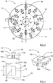
- shows a bottom view of a tool holder disc;
- Figure 4
- shows a perspective view, a side view and a top view of a carrier plate;
- Figure 5
- shows a transverse section of a groove
- Figure 6A
- shows a longitudinal section of a groove without a carrier plate;
- Figure 6B
- shows a longitudinal section of a groove with a semi-attached carrier plate;
- Figure 6C
- shows a longitudinal section of a groove with an attached carrier plate;
- Figure 7
- shows a perspective view of a transmission arrangement;
- Figure 8
- shows a side view of a transmission arrangement;
- Figure 9
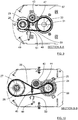
- shows a first section view of the transmission arrangement;
- Figure 10
- shows a second section view of the transmission arrangement;
- Figure 11
- shows a schematic perspective view of the transmission arrangement;
- Figure 12A
- shows a releasable handle in a hooked position;
- Figure 12B
- shows a releasable handle in an unhooked position;
- Figure 13
- shows a schematic perspective view of the transmission arrangement mounted to the floor surfacing machine;
- Figure 14
- shows a schematic perspective view of transmission arrangement subassemblies that have been removed from the floor surfacing machine;
- Figure 15
- shows a bottom view of an alternative tool holder disc;
- Figure 16
- shows a further example and corresponds to
Figure 10 ; and - Figure 17
- shows a further example and corresponds to
Figure 9 . -
Figure 1 and Figure 2 show a side and a top view of afloor surfacing machine 1, for example a floor grinding or polishing machine. Thefloor surfacing machine 1 has aframe 2 that is carried by afirst wheel 3 and asecond wheel 4. Theframe 2 comprises ahandle arrangement 7 allowing an operator to move the machine over aground surface 5 to be surfaced. The surfacing machine comprises acombustion engine 8 that is mounted to anengine mounting bracket 36 and is adapted to propel, a grinding head that is constituted of atool holder disc 6 having abottom side 6a that is adapted to face theground surface 5 during the grinding process. Thetool holder disc 6 is partially enclosed by adust cover 37, leaving at least thebottom side 6a uncovered such that it is enabled to contact theground surface 5 during the grinding process. - With reference also to
Figure 3 , thetool holder disc 6 has a first set of fixing means in the form of radially extending first grooves 10 (only one groove is indicated by reference number in the Figure for reasons of clarity) that are equidistantly distributed, both from arotational center 13 of thetool holder disc 6, and along a firstcircular extension 14 running around therotational center 13 of thetool holder disc 6. Thetool holder disc 6 also has a second set of fixing means in the form of radially extending second grooves 12 (only one indicated by reference number in the Figure for reasons of clarity) that are equidistantly distributed, both from therotational center 13 of thetool holder disc 6, and along a secondcircular extension 15 running around therotational center 13 of thetool holder disc 6. - The first
circular extension 14 runs such that it passes through thefirst grooves 10 as close to therotational center 13 of thetool holder disc 6 as possible, and the secondcircular extension 15 runs such that it passes through thesecond grooves 12 as close to therotational center 13 of thetool holder disc 6 as possible. The firstcircular extension 14 is closer to therotational center 13 of thetool holder disc 6 than the secondcircular extension 15. - With reference also to
Figure 4 , showing a perspective view, a side view and a top view of acarrier plate 16, andFigure 5 , showing a transverse section of agroove 12, thegrooves mountable carrier plates 16, each comprisingabrasive elements 17, at thebottom side 6a of thetool holder disc 6. For this purpose, thegrooves rotational center 13 of thetool holder disc 6, and eachgroove rotational center 13 of thetool holder disc 6. Furthermore, eachgroove 12 has inclinedinner walls rotational center 13 of thetool holder disc 6. - Each
carrier plate 16 has anunderside 16a and atop side 16b, on whichtop side 16b a radial grippingmember 18 is fastened. The grippingmember 18 preferably extends along a path from aninnermost end 16c to a farthest outend 16d of thecarrier plate 16 with respect to therotational center 13 of thetool holder disc 6 when the carrier plate is mounted. The grippingmember 18 has a conical shape with its base facing towards saidinnermost end 16c and the tip towards said farthest outend 16d. - Further, the gripping
member 18 has twoside walls top side 16a of thecarrier plate 16. Said inclination is arranged to correspond to the inclination of the inclinedinner walls grooves member 18 falls below the length L2 of thegrooves - According to the present disclosure, with reference also to
Figure 6A that show a longitudinal section of agroove 12, thetool holder disc 6 comprises aspring plate 23 for eachgrove 12, placed and fastened on anupper side 6b of thetool holder disc 6, whichupper side 6b is adapted to face away fromground surface 5 during the grinding process and being opposite to thelower side 6a. - When attaching a
carrier plate 16 to agroove tool holder disc 6 is first put down with itsbottom side 6a turned upwards exposing thegrooves grooves 12 is chosen for mounting acarrier plate 16, and as shown inFigure 6B , the grippingmember 18 of thecarrier plate 16 is placed into the wider part of the chosengroove 12 with theinnermost end 16c of saidcarrier plate 16 pointing towards therotational center 13 of thetool holder disc 2. Thecarrier plate 16 is subsequently radially pulled toward the outermost narrower portion of the chosengroove pressure member 23a of thespring plate 23 towards an upper side 18b of the grippingmember 18, fixing thecarrier plate 16 by means of co-operation between themating groove member 18. With reference also toFigure 6C , when sufficiently pulled toward the outermost narrower portion of the chosengroove pressure member 23a will act on aninner side 18a of the grippingmember 18, where saidinner side 18a is facing therotational center 13 of thetool holder disc 6 when mounted. Generally, eachpressure member 23a is adapted to act on at least an edge of aninner side 18a of the grippingmember 18 when mounted. - According to some aspects, the
pressure member 23a will not be in contact with theinner side 18a of the grippingmember 18 when the grippingmember 18 is moved to a working position at the outermost narrower portion of the chosengroove pressure member 23a will contact theinner side 18a of the grippingmember 18 when the grippingmember 18 is moved from the working position, preventing it from further movement. - Alternatively, the
pressure member 23a will always be in contact with theinner side 18a of the grippingmember 18 when mounted, even in the working position. - Both alternatives above are to be interpreted to fall within a general definition that each biasing
member 23 is adapted to act on at least an edge of aninner side 18a of the grippingmember 18 when mounted. - The inclined
inner walls grooves corresponding side walls member 18 such that thecarrier plates 16 are kept in thecorresponding grooves spring plate 23, thecarrier plates 16 are prevented from moving towards therotational center 13 of thetool holder disc 6, for example during transport between different working places. - When a
carrier plate 16 is to be released, thecarrier plate 16 is moved towards therotational center 13 of thetool holder disc 6, against the spring force of the apressure member 23a such that thepressure member 23a is returned to the upper side 18b of the grippingmember 18 from theinner side 18a of the grippingmember 18. Thepressure member 23a is pressing towards the upper side 18b of the grippingmember 18 while the grippingmember 18 is pulled towards therotational center 13 until it can be removed from thegroove 12. - In
Figure 15 , it is shown how thespring plates 23 are attached to theupper side 6b of thetool holder disc 6 for onegroove 12. According to some aspects, as shown here, thespring plate 23 comprises twoside parts groove 12 and are attached to thetool holder disc 6 withappropriate attachment elements - When the
combustion engine 8 is used for propelling a single grinding head that is constituted of thetool holder disc 6, the rotational speed of theengine 8 may need to be lowered by means of a transmission arrangement. Previously, such a transmission arrangement has been in the form of a one-step belt transmission that comprises a transmission belt and two belt pulleys of different dimensions; one belt pulley is connected to an engine axis and another belt pulley is connected to a grinding head axis that in turn is connected to the single grinding head, where the engine is positioned a certain distance away from the grinding head axle,. A design like this results in that the tool holder disc is pivoting around the wheel axle which in turn requires that thetool holder disc 6 is levelled with the floor by adjustment the height of awheel axle 55 after every change of abrasive elements, otherwise the wear of the abrasive elements will be uneven and the grinding result will not be good. A more user-friendly abrasive element change is therefore desired. - It is also desired obtain an improved engine symmetry with respect to the single tool holder disc in order to increase maneuverability and ease of handling of the
floor surfacing machine 1. - In order to overcome the above problems, not being a part of the present disclosure, a
compact transmission arrangement 38 is provided as shown in a perspective view inFigure 7 . InFigure 8 a side view of thetransmission arrangement 38 is shown, inFigure 9 a first section is shown and inFigure 10 a second section is shown.Figure 11 show a schematic perspective view of how thetransmission arrangement 38 is constituted. - The
engine 8 comprises anengine axle 24 that runs along, and is rotatable about, afirst axis 33 and is connected to afirst belt pulley 25 that is arranged to drive a firstendless belt 26 that further is adapted to drive asecond belt pulley 27 that is connected to anintermediate part 65 that runs along, and is rotatable about, asecond axis 34. Theintermediate part 65 is further connected to athird belt pulley 29 that is mounted closer to thetool holder disc 6 than thesecond belt pulley 27. In theintermediate part 65, afirst pulley axle 28 is running, and preferably there is a bearingarrangement 66 between thefirst pulley axle 28 and theintermediate part 65. Thefirst pulley axle 28 is running along thesecond axis 34 and is mounted to alower housing plate 67, opposite anupper housing plate 68. Thefirst pulley axle 28 can according to some aspects be mounted to another part, for example theupper housing plate 68. - The
third belt pulley 29 is arranged to drive a secondendless belt 30 that further is adapted to drive afourth belt pulley 31 that is connected to asecond pulley axle 32 that runs along, and is rotatable about, athird axis 35. Thesecond pulley axle 32 is adapted to propel thetool holder disc 6. - The
first axis 33, thesecond axis 34 and thethird axis 35 are all adapted to run mutually parallel. There is a shortest first distance ri between thefirst axis 33 and thethird axis 35, there is a shortest second distance r2 between thesecond axis 34 and thethird axis 35, and there is a shortest third distance r3 between thefirst axis 33 and thesecond axis 34. The first distance ri falls below the third distance r3. - According to some aspects, the first distance ri falls below the second distance r2.
- Having belt pulleys 25, 27, 29, 31 arranged in this manner such that two
endless belts rotating parts - As shown in
Figure 11 , thefirst belt pulley 25 has a first outer diameter di, thesecond belt pulley 27 has a second outer diameter d2, thethird belt pulley 29 has a third outer diameter d3 and thefourth belt pulley 31 has a fourth outer diameter d4. - According to some aspects, the second outer diameter d2 exceeds the first outer diameter di, and the fourth outer diameter d4 exceeds the third outer diameter d3.
- According to some aspects the third outer diameter d3 is about 1,5 times the second outer diameter d2, and the second outer diameter d2 is about twice the first outer diameter d1. According to some aspects the third outer diameter d3 is about 200 mm, the second outer diameter d2 is about 130 mm and the first outer diameter d1 is about 70 mm.
- According to some aspects, the first distance ri equals zero, such that the
first axis 33 and thethird axis 35 coincide, theengine axle 24 being the same as thesecond pulley axle 32. - In this manner, the
second pulley axle 32, that is adapted to propel thetool holder disc 6, is arranged towards theengine axle 24 relative thefirst pulley axle 28, and this results in that theengine 8 obtains a position closer to thetool holder disc 6 such that theengine 8 obtains an improved symmetry with respect to thetool holder disc 6. - The
compact transmission arrangement 38, comprising saidaxles endless belts engine mounting bracket 36 and thedust cover 37, such that a compact integratedfront part 39 that is connected to theframe 2 in a pivoting manner at a pivotingaxis 59 is formed as shown inFigure 13 and Figure 14 , not being part of the present invention. According to some aspects, theupper housing plate 68 and theengine mounting bracket 36 is one and the same part as indicated inFigure 13 and Figure 14 . - As shown in
Figure 1, Figure 2 ,Figure 13 and Figure 14 , thedust cover 37 comprises a first mountingflange 40 and a second mountingflange 41, which mountingflanges engine mounting bracket 36 and are connected to theframe 2 in a pivoting manner by means of connectingpins - By means of this arrangement, not being part of the present invention, the center of gravity of the compact integrated
front part 39 can be placed in, or at least relatively close to, the pivotingaxis 59 connecting thedust cover 37 to theframe 2. Thedust cover 37 will strive to have a positon relative theframe 2 where thetool holder disc 6 obtains the most complete contact with the ground that is possible, dispensing with any need of wheel adjustment when changingabrasive elements 17 and their associatedcarrier plates 16. - A balanced grinding head in the form of the
tool holder disc 6 above that has the possibility to pivot provides many advantages. There will be no need to adjust the wheel axle height after every tool change. Thefloor surfacing machine 1 will grind smoothly across the whole tool holder disc'slower surface 6a, from changing to new tools until completely worn tools, not requiring any user adjustments. - The
endless belts engine 8 and achieve longer belt life time. The general principle of belt tensioners can be divided into two different variants, passive and active. Passive belt tensioners are mounted and fixed in one position giving the strived belt tensioning. Active belt tensioners on the other hand can, once they are installed, adapt to the elongation of the belt over time, usually by means of a spring. - Passive belt tensioners are, since they need to be checked and re-tensioned continuously as the belt lengthen, more service demanding than active belt tensioners. Small belt slack, during even short period of time, shortens the belt life dramatically. When using passive belt tensioners, it is also possible that a user tensions the endless belt more than intended, which will also shorten the life of the belts, pulleys and bearings.
- Active belt tensioners often have more parts, are more expensive, and have a more complex design than the passive variant. On the other hand, they are less, if at all, service demanding. All sudden slack that appears during belt use is taken up by a spring load, maintaining proper belt tension during all time of use. A typical active belt tensioner is constituted by a tensioning pulley mounted on an arm that is pivoting around an axle placed at a suitable position next to the belt and the driving and driven pulleys.
- The space available at the
transmission arrangement 38 is limited, requiring a space efficient belt tensioner, where it also is desired that belt, pulley and bearing replacement can be done quickly and easily. Needing a workshop to replace an endless belt takes too much time and is too expensive for the user, instead it should be possible to do it on the floor where it broke down. - As indicated with arrows A1, A2 in
Figure 11 , the firstendless belt 26 and the secondendless belt 30 need to be subject of a certain tension. With reference toFigure 9, Figure 10 andFigure 14 , this tension is inflicted by means of corresponding tension pulleys, afirst tension pulley 42 and asecond tension pulley 43. - The
first tension pulley 42 is rotatably mounted to afirst pressure part 44 that is pivotably mounted to theengine axle 24, where thefirst pressure part 44 is connected to afirst spring 45 that is adapted to exert a spring load at thefirst pressure part 44 such that thefirst tension pulley 42 is pressed towards the firstendless belt 26. By means of a firstreleasable handle 46, a user can release the spring load at thefirst pressure part 44 such that thefirst tension pulley 42 releases the firstendless belt 26, for example when the firstendless belt 26 is replaced. - Correspondingly, the
second tension pulley 43 is rotatably mounted to asecond pressure part 47 that is pivotably mounted to thesecond pulley axle 32, where thesecond pressure part 47 is connected to asecond spring 48 that is adapted to exert a spring load at thesecond pressure part 47 such that thesecond tension pulley 43 is pressed towards the secondendless belt 30. By means of a secondreleasable handle 49, a user can release the spring load at thesecond pressure part 47 such that thesecond tension pulley 43 releases the secondendless belt 30, for example when the secondendless belt 30 is replaced. - At least one of the
pressure parts second pressure part 47 can be pivotably mounted to thefirst pulley axle 28 instead as will be described in a further example. - The tension pulleys 42, 43 are both mounted such that they contact the corresponding
endless belt corresponding pulley axle first tension pulley 42 is mounted such that it contacts the firstendless belt 26 after theengine axle 24 in the direction of the first endless belt's running movement, and thesecond tension pulley 43 is mounted such that it contacts the secondendless belt 30 after thefirst pulley axle 28 in the direction of the second endless belt's running movement. - Each one of the tension pulleys 42, 43 is thus adapted to rotate around the same axis as one of the
pulleys handles endless belts endless belt handle bracket Figure 12a in a hooked position and inFigure 12b in an unhooked position, not being part of the present invention. - An active spring loaded belt tensioner is thus provided that gives longer life time of the
endless belts pressure parts pulleys handles - With reference to
Figure 16 and Figure 17 , whereFigure 16 corresponds toFigure 10 andFigure 17 corresponds toFigure 9 , an alternative example will be described, not being part of the present invention. As indicated with the arrows A1, A2 inFigure 11 , the firstendless belt 26 and the secondendless belt 30 need to be subject of a certain tension that here is inflicted by means of corresponding tension pulleys, a first tension pulley 42' and a second tension pulley 43'. - In this example, according to some aspects, the first tension pulley 42' is rotatably mounted to a first pressure part 44' that is pivotably mounted to a
separate pivot axle 64, where the first pressure part 44' is connected to a first spring 45' that is adapted to exert a spring load at the first pressure part 44' such that the first tension pulley 42' is pressed towards the firstendless belt 26. By means of a first releasable handle 46', a user can release the spring load at the first pressure part 44' such that the first tension pulley 42' releases the firstendless belt 26, for example when the firstendless belt 26 is replaced. - Correspondingly, the second tension pulley 43' is rotatably mounted to a second pressure part 47' that is pivotably mounted to the
first pulley axle 28, where the second pressure part 47' is connected to a second spring 48' that is adapted to exert a spring load at the second pressure part 47' such that the second tension pulley 43' is pressed towards the secondendless belt 30. By means of a second releasable handle 49', a user can release the spring load at the second pressure part 47' such that the second tension pulley 43' releases the secondendless belt 30, for example when the secondendless belt 30 is replaced. - As described for the previous example, the tension pulleys 42', 43' are both mounted such that they contact the corresponding
endless belt corresponding driving axle - The belt tensioner springs 45', 48' have been equipped with handles 46', 49' for easy tensioning and releasing the
endless belts endless belt - According to some aspects, with reference also to
Figure 11 and not being part of the present invention, the second pressure part 47' is instead pivotably mounted to theintermediate part 65. In that case, there should be a bearing arrangement positioned between the second pressure part 47' and theintermediate part 65. - Generally, the
second pressure part 47, 47' is rotatable about thesecond axis 34, and is thus at least indirectly pivotably mounted to thefirst pulley axle 28. The mounting is for example indirect when the second pressure part 47' is pivotably mounted to theintermediate part 65. - For all these kinds of arrangements, according to some aspects, in dependence of the spring force, other types of arrangements for tensioning and releasing the
endless belts - In view of the above examples, at least one
pressure parts pulleys tension pulley corresponding pressure part pressure part axle pressure part corresponding spring corresponding pressure part tension pulley pulley axle intermediate part 65 connecting belt pulleys 27, 29 that are rotatable around acommon axis 34, or by themotor axle 24. - With reference to
Figure 13 and Figure 14 , not being part of the present invention, in order to ease the maintenance of thetransmission arrangement 38, the internal parts of thetransmission arrangement 38 have been divided intosmaller subassemblies floor surfacing machine 1 individually, according to some aspects by releasing holding screws at the underside of thedust cover 37. This means that there is no need to demount the engine or the frame if for example a pulley or a bearing needs to be replaced. - The present disclosure is not limited to the above, but may vary freely within the scope of the dependent claims. For example,
tool holder disc 6 may be arranged for any suitable type of surfacing; being equipped for grinding or polishing. The number ofwheels - According to some aspects, each spring plate is generally constituted by a biasing
member 23. - According to some aspects, the combustion engine is constituted by another type of motor, such as an electric motor.
- According to some aspects, the
floor surfacing machine 1 is a grinding machine. - Generally, the present disclosure relates to a
floor surfacing machine 1 comprising aframe 2 that is carried by at least twowheels floor surfacing machine 1 further comprises amotor 8 and atool holder disc 6 adapted to be driven by themotor 8 and having arotational center 13, abottom side 6a that is adapted to face aground surface 5 and a plurality ofgrooves rotational center 13, where eachgroove rotational center 13 and inclinedinner walls rotational center 13, where eachgroove member 18 comprised in acarrier plate 16 carryingabrasive elements 17, where each grippingmember 18 has a conical shape tapering radially outwards from saidrotational center 13 when mounted and twoside walls inner walls grooves tool holder disc 6 comprises a biasingmember 23 for at least onegroove member 23 is adapted to protrude into a correspondinggroove member 18 from sliding out of thegroove - Each biasing
member 23 is constituted by aspring plate 23 that comprises apressure member 23a that is adapted to act on at least an edge of aninner side 18a of the grippingmember 18 when mounted, where saidinner side 18a is facing therotational center 13 of thetool holder disc 6 when mounted, - The
pressure member 23a will either always contact theinner side 18a of the grippingmember 18 when mounted, or only when the grippingmember 18 is moved from a working position of the correspondinggroove pressure member 23a is in contact with theinner side 18a of the grippingmember 18, it is adapted to then prevent further movement of the grippingmember 18 until a spring force of thepressure member 23a is overcome by continued movement of the grippingmember 18, enabling thecarrier plate 16 to be released. - According to some aspects, when a
carrier plate 16 is mounted to agroove groove pressure member 23a of thespring plate 23 towards an upper side 18b of the grippingmember 18, and when sufficiently pulled toward the outermost narrower portion of the chosengroove pressure member 23a is adapted to leave the upper side 18b of the grippingmember 18 and act on aninner side 18a of the grippingmember 18. - According to some aspects, each
spring plate 23 comprises twoside parts groove 12 and are attached to thetool holder disc 6 withappropriate attachment elements - According to some aspects, the
pressure member 23a will contact theinner side 18a of the grippingmember 18 when the grippingmember 18 is moved from a working position at the outermost narrower portion of the chosengroove
Claims (12)
- A floor surfacing machine (1) comprising a frame (2) that is carried by at least two wheels (3, 4), where the floor surfacing machine (1) further comprises a motor (8) and a tool holder disc (6) adapted to be driven by the motor (8) and having a rotational center (13), a bottom side (6a) that is adapted to face a ground surface (5) and a plurality of grooves (10, 12) that extend radially from said rotational center (13), where each groove (10, 12) has a conical shape tapering radially outwards from said rotational center (13) and inclined inner walls (21, 22) propagating away from said rotational center (13), where each groove (10, 12) is adapted to receive a corresponding detachably mountable gripping member (18) comprised in a carrier plate (16) carrying abrasive elements (17), where each gripping member (18) has a conical shape tapering radially outwards from said rotational center (13) when mounted and two side walls (19, 20) which have an inclination that is arranged to correspond to the inclination of the inclined inner walls (21, 22) of the grooves (10, 12), where the tool holder disc (6) comprises a biasing member (23) for at least one groove (10, 12), where each biasing member (23) is adapted to protrude into a corresponding groove (10, 12) and prevent a corresponding gripping member (18) from sliding out of the groove (10, 12) when mounted, where each biasing member (23) is constituted by a spring plate (23) that comprises a pressure member (23a) that is adapted to act on at least an edge of an inner side (18a) of the gripping member (18) when mounted, where said inner side (18a) is facing the rotational center (13) of the tool holder disc (6) when mounted, where the pressure member (23a) either always will contact the inner side (18a) of the gripping member (18) when mounted, or only when the gripping member (18) is moved from a working position of the corresponding groove (10, 12), wherein when the pressure member (23a) is in contact with the inner side (18a) of the gripping member (18), it is adapted to prevent further movement of the gripping member (18) until a spring force of the pressure member (23a) is overcome by continued movement of the gripping member (18), enabling the carrier plate (16) to be released.
- The floor surfacing machine (1) according to claim 1, wherein when a carrier plate (16) is mounted to a groove (10, 12), it is radially pulled toward an outermost narrower portion of the chosen groove (10, 12) under the load of a pressure member (23a) of the spring plate (23) towards an upper side (18b) of the gripping member (18), and when sufficiently pulled toward the outermost narrower portion of the chosen groove (10, 12), the pressure member (23a) is adapted to leave the upper side (18b) of the gripping member (18) and act on an inner side (18a) of the gripping member (18).
- The floor surfacing machine (1) according to claim 2, wherein each spring plate (23) comprises two side parts (60, 61) that extend out from a corresponding groove (12) and are attached to the tool holder disc (6) with appropriate attachment elements (62, 63).
- The floor surfacing machine (1) according to any one of the claims 2 or 3, wherein the pressure member (23a) will contact the inner side (18a) of the gripping member (18) when the gripping member (18) is moved from a working position at the outermost narrower portion of the chosen groove (10, 12).
- The floor surfacing machine (1) according to any one of the preceding claims, wherein the floor surfacing machine (1) comprises an engine mounting bracket (36) to which the motor (8) is mounted, and a dust cover (37) that is adapted to partially enclose the tool holder disc (6), leaving at least the bottom side (6a) uncovered such that it is enabled to contact the ground surface (5).
- The floor surfacing machine (1) according to any one of the preceding claims, wherein the floor surfacing machine (1) is a grinding machine.
- A tool holder disc (6) adapted to be driven by a motor (8) of a floor surfacing machine (1) and having a rotational center (13), a bottom side (6a) that is adapted to face a ground surface (5) and a plurality of grooves (10, 12) that extend radially from said rotational center (13), where each groove (10, 12) has a conical shape tapering radially outwards from said rotational center (13) and inclined inner walls (21, 22) propagating away from said rotational center (13), where each groove (10, 12) is adapted to receive a corresponding detachably mountable gripping member (18) comprised in a carrier plate (16) carrying abrasive elements (17), where each gripping member (18) has a conical shape tapering radially outwards from said rotational center (13) when mounted and two side walls (19, 20) which have an inclination that is arranged to correspond to the inclination of the inclined inner walls (21, 22) of the grooves (10, 12), where the tool holder disc (6) comprises a biasing member (23) for at least one groove (10, 12), where each biasing member (23) is adapted to protrude into a corresponding groove (10, 12) and prevent a corresponding gripping member (18) from sliding out of the groove (10, 12) when mounted, where each biasing member (23) is constituted by a spring plate (23) that comprises a pressure member (23a) that is adapted to act on at least an edge of an inner side (18a) of the gripping member (18) when mounted, where said inner side (18a) is facing the rotational center (13) of the tool holder disc (6) when mounted, where the pressure member (23a) either always will contact the inner side (18a) of the gripping member (18) when mounted, or only when the gripping member (18) is moved from a working position of the corresponding groove (10, 12), wherein when the pressure member (23a) is in contact with the inner side (18a) of the gripping member (18), it is adapted to prevent further movement of the gripping member (18) until a spring force of the pressure member (23a) is overcome by continued movement of the gripping member (18), enabling the carrier plate (16) to be released.
- The tool holder disc (6) according to claim 7, wherein when a carrier plate (16) is mounted to a groove (10, 12), it is radially pulled toward an outermost narrower portion of the chosen groove (10, 12) under the load of a pressure member (23a) of the spring plate (23) towards an upper side (18b) of the gripping member (18), and when sufficiently pulled toward the outermost narrower portion of the chosen groove (10, 12), the pressure member (23a) is adapted to leave the upper side (18b) of the gripping member (18) and act on an inner side (18a) of the gripping member (18).
- The tool holder disc (6) according to claim 8, wherein each spring plate (23) comprises two side parts (60, 61) that extend out from a corresponding groove (12) and are attached to the tool holder disc (6) with appropriate attachment elements (62, 63).
- The tool holder disc (6) according to any one of the claims 8 or 9, wherein the pressure member (23a) will contact the inner side (18a) of the gripping member (18) when the gripping member (18) is moved from a working position at the outermost narrower portion of the chosen groove (10, 12).
- A floor surfacing machine comprising the tool holder disc (6) according to any one of the claims 7-10.
- The floor surfacing machine according to claim 11, wherein the floor surfacing machine is a grinding machine.
Applications Claiming Priority (3)
| Application Number | Priority Date | Filing Date | Title |
|---|---|---|---|
| SE1850375A SE542372C2 (en) | 2018-04-04 | 2018-04-04 | A floor surfacing machine with a tool holder disc comprising a biasing member |
| PCT/SE2019/050306 WO2019194732A1 (en) | 2018-04-04 | 2019-04-03 | A transmission arrangement for a floor surfacing machine comprising a first and second idle pulley, both pivotable around a common pivot axis |
| EP19780814.0A EP3775618B1 (en) | 2018-04-04 | 2019-04-03 | A transmission arrangement for a floor surfacing machine comprising a first and second idle pulley, both pivotable around a common pivot axis |
Related Parent Applications (2)
| Application Number | Title | Priority Date | Filing Date |
|---|---|---|---|
| EP19780814.0A Division-Into EP3775618B1 (en) | 2018-04-04 | 2019-04-03 | A transmission arrangement for a floor surfacing machine comprising a first and second idle pulley, both pivotable around a common pivot axis |
| EP19780814.0A Division EP3775618B1 (en) | 2018-04-04 | 2019-04-03 | A transmission arrangement for a floor surfacing machine comprising a first and second idle pulley, both pivotable around a common pivot axis |
Publications (1)
| Publication Number | Publication Date |
|---|---|
| EP3825576A1 true EP3825576A1 (en) | 2021-05-26 |
Family
ID=68101549
Family Applications (2)
| Application Number | Title | Priority Date | Filing Date |
|---|---|---|---|
| EP19780814.0A Active EP3775618B1 (en) | 2018-04-04 | 2019-04-03 | A transmission arrangement for a floor surfacing machine comprising a first and second idle pulley, both pivotable around a common pivot axis |
| EP20205095.1A Withdrawn EP3825576A1 (en) | 2018-04-04 | 2019-04-03 | A floor surfacing machine with a tool holder disc comprising a biasing member |
Family Applications Before (1)
| Application Number | Title | Priority Date | Filing Date |
|---|---|---|---|
| EP19780814.0A Active EP3775618B1 (en) | 2018-04-04 | 2019-04-03 | A transmission arrangement for a floor surfacing machine comprising a first and second idle pulley, both pivotable around a common pivot axis |
Country Status (6)
| Country | Link |
|---|---|
| US (1) | US12203548B2 (en) |
| EP (2) | EP3775618B1 (en) |
| CN (2) | CN112353301A (en) |
| AU (2) | AU2019247353B2 (en) |
| SE (2) | SE542372C2 (en) |
| WO (1) | WO2019194732A1 (en) |
Cited By (1)
| Publication number | Priority date | Publication date | Assignee | Title |
|---|---|---|---|---|
| DE102022111193A1 (en) | 2022-05-05 | 2023-11-09 | Friedrich August Picard Gmbh & Co. Kg | Sanding block |
Families Citing this family (3)
| Publication number | Priority date | Publication date | Assignee | Title |
|---|---|---|---|---|
| US11396085B2 (en) * | 2017-09-15 | 2022-07-26 | Diamond Productions Ltd. | Adapter for coupling abrasive elements to a floor finishing machine |
| CN111577080B (en) * | 2020-05-27 | 2021-02-23 | 浙江冠石建筑科技有限公司 | Entrance door security device |
| IT202200025833A1 (en) * | 2022-12-16 | 2024-06-16 | Ital Res & Innovation Srl | SELECTIVE DRIVE COMBINED MACHINE |
Citations (4)
| Publication number | Priority date | Publication date | Assignee | Title |
|---|---|---|---|---|
| US20080176498A1 (en) * | 2007-01-18 | 2008-07-24 | Nufinish Corporation | Grinding tools and apparatus for securing grinding tools to grinding machines |
| EP2337653A1 (en) | 2008-09-05 | 2011-06-29 | Husqvarna AB | Double row abrasive disc |
| WO2014055031A1 (en) * | 2012-10-05 | 2014-04-10 | Scanmaskin Sverige Ab | Holder arrangement for grinding tools |
| EP2992998A1 (en) * | 2014-09-05 | 2016-03-09 | M.B.H. Developpement | Rotary disc with removable abrasive segments |
Family Cites Families (52)
| Publication number | Priority date | Publication date | Assignee | Title |
|---|---|---|---|---|
| US1660520A (en) | 1924-08-13 | 1928-02-28 | Anton E Nielsen | Belt-tensioning apparatus |
| US1641799A (en) | 1925-08-31 | 1927-09-06 | Springfield Mfg Co | Sectional grinding wheel |
| US2541812A (en) | 1947-10-30 | 1951-02-13 | Walter S Finnell | Floor processing machine |
| US2662454A (en) | 1948-04-12 | 1953-12-15 | Whiteman Marvin Edwin | Float trowel for cement floor finishers |
| US2674896A (en) | 1951-09-22 | 1954-04-13 | Advance Machine Co | Drive unit for floor polishing machines and the like |
| US2765483A (en) | 1953-09-11 | 1956-10-09 | Blanc Gabriel G Le | Sweeping machine |
| GB746802A (en) * | 1954-04-28 | 1956-03-21 | Frank Philip Lalonde | Surface treating machines |
| US2710416A (en) | 1954-04-30 | 1955-06-14 | Lalonde Frank Philip | Floor surfacing machines |
| GB766034A (en) | 1955-03-31 | 1957-01-16 | Frank Philip Lalonde | Improvements in floor treating machines |
| US3121982A (en) | 1960-08-25 | 1964-02-25 | Cons Diamond Dev Company Ltd | Grinding wheel with adjustable abrasive segments |
| GB944549A (en) | 1961-03-23 | 1963-12-18 | Diskus Werke Frankfurt Main Ag | Device for the quick attachment of grinding-wheel units of segments on a carrier plate |
| GB918162A (en) * | 1961-08-22 | 1963-02-13 | Macalisters Ltd | Device for use in conjunction with conveyor belts and the like |
| AU437509B2 (en) | 1969-03-04 | 1973-07-02 | Floor polisher drive means | |
| US3800612A (en) | 1972-10-10 | 1974-04-02 | Int Harvester Co | Belt drive apparatus |
| US3934377A (en) | 1974-06-12 | 1976-01-27 | Stone Construction Equipment, Inc. | Concrete surface grinder |
| AU501254B2 (en) | 1976-03-22 | 1979-06-14 | P. J Brazzale | Belt drive means for floor polisher |
| JPS5485552U (en) | 1977-11-30 | 1979-06-16 | ||
| US4564098A (en) * | 1979-06-21 | 1986-01-14 | Hormann Kg | Drive assembly for door operator |
| US4416647A (en) * | 1981-05-26 | 1983-11-22 | Dayco Corporation | Belt tensioner |
| FR2542836B1 (en) * | 1983-03-17 | 1985-06-21 | Plazanet Maurice | MACHINE FOR CONDITIONING AND / OR MAINTAINING FLOORS |
| SE446552B (en) | 1985-05-06 | 1986-09-22 | Dynapac Ab | Safety coupling for V-belt driven machines |
| US5221236A (en) * | 1990-07-10 | 1993-06-22 | Raymer Matthew C | Belt tensioning device for belt driven bicycle |
| US5608939A (en) | 1995-08-31 | 1997-03-11 | Castex Incorporated | Motor and driver mount diaphragm burnisher |
| ES2147896T3 (en) | 1996-02-09 | 2000-10-01 | Unilever Nv | APPARATUS FOR TREATING A SURFACE WITH A ROTATING ELEMENT. |
| US5776025A (en) * | 1996-09-25 | 1998-07-07 | Eastman Kodak Company | Adjustable self-aligning belt tensioner |
| JPH10184827A (en) * | 1996-10-23 | 1998-07-14 | Aisin Seiki Co Ltd | Hydraulic auto tensioner |
| US5885139A (en) | 1997-07-15 | 1999-03-23 | Lemieux; Francois | Floor covering stripping and floor re-surfacing machine |
| US6176071B1 (en) * | 1999-09-10 | 2001-01-23 | Deere & Company | Tensioning idler assembly for mower deck belt drive |
| DE60116888T2 (en) | 2000-10-03 | 2006-10-26 | The Gates Corp., Denver | DOUBLE, LINEAR BELT TENSION |
| DE10109570A1 (en) | 2001-02-28 | 2002-09-05 | Ina Schaeffler Kg | Device for decoupling rotational irregularities |
| US7241210B2 (en) * | 2001-07-16 | 2007-07-10 | Holland Industriele Diamantwerken B.V. | Floor treating machine comprising individually driven discs |
| ITTO20030601A1 (en) * | 2003-08-01 | 2005-02-02 | Dayco Europe Srl | TENSIONER FOR A TRANSMISSION BELT OF A MOTOR VEHICLE. |
| US20070042846A1 (en) | 2005-08-19 | 2007-02-22 | Van Vliet Johannes P | Floor treating machine with improved rotary drive |
| US7690970B2 (en) * | 2007-01-19 | 2010-04-06 | Epoxy-Tech, Inc. | Abrasive preparation device with an improved abrasion element assembly |
| US7563156B2 (en) | 2007-09-13 | 2009-07-21 | National Carpet Equipment, Inc. | Planetary grinder |
| ES2543688T3 (en) * | 2007-11-16 | 2015-08-21 | Ketten-Wulf Betriebs-Gmbh | Chain drive and drive means |
| KR100931641B1 (en) | 2009-07-28 | 2009-12-14 | (주)성심 | Gear tool box structure for polishing machine |
| US9133762B2 (en) * | 2009-09-18 | 2015-09-15 | GM Global Technology Operations LLC | Drive belt tensioner for motor generator unit |
| US8366517B2 (en) * | 2009-12-07 | 2013-02-05 | Design Technologies Llc | Floor treatment apparatus with tensioning pulley drive |
| DE202010010103U1 (en) * | 2010-07-09 | 2011-11-04 | Sudhaus Gmbh & Co. Kg | Castor for suitcases, luggage, transport containers or the like. |
| CN101934505A (en) * | 2010-08-17 | 2011-01-05 | 何�轩 | Grinding disc and high-speed rail bridge grinder provided with same |
| CN102267106B (en) * | 2011-07-19 | 2013-03-13 | 沈阳工程学院 | Disc type movable polishing grinding tool |
| US8684796B2 (en) | 2011-10-04 | 2014-04-01 | Krmc, Llc | Floor grinding and polishing machine |
| DE102012201211A1 (en) | 2012-01-27 | 2013-08-01 | Schaeffler Technologies AG & Co. KG | Clamping device for belt drive of combustion engine, has steering wheel that is arranged linearly and rotationally movable in belt drive |
| US9777806B2 (en) * | 2012-03-28 | 2017-10-03 | Dayco Ip Holdings, Llc | Sealed belt tensioning device |
| CN202640058U (en) | 2012-07-04 | 2013-01-02 | 易际东 | Multifunctional terrace crystal face machine with two-stage retarding mechanism |
| KR20150099898A (en) | 2014-02-24 | 2015-09-02 | 주식회사 폴리시스 | Rotation plate equipped on polishing machine |
| WO2015167376A1 (en) * | 2014-04-30 | 2015-11-05 | Husqvarna Ab | Floor grinding machine |
| DE102014007878A1 (en) | 2014-05-24 | 2015-11-26 | Andreas Stihl Ag & Co. Kg | Hand-held implement |
| DE102014117094A1 (en) * | 2014-11-21 | 2016-05-25 | Muhr Und Bender Kg | Belt tensioner |
| SE539452C2 (en) * | 2015-12-02 | 2017-09-26 | Husqvarna Ab | Blade shaft drive |
| SE542092C2 (en) | 2016-06-03 | 2020-02-25 | Husqvarna Ab | Grinding head for floor grinding machine and a floor grinding machine comprising such a grinding head |
-
2018
- 2018-04-04 SE SE1850375A patent/SE542372C2/en not_active IP Right Cessation
-
2019
- 2019-04-03 EP EP19780814.0A patent/EP3775618B1/en active Active
- 2019-04-03 CN CN202011241542.XA patent/CN112353301A/en active Pending
- 2019-04-03 WO PCT/SE2019/050306 patent/WO2019194732A1/en not_active Ceased
- 2019-04-03 US US17/044,857 patent/US12203548B2/en active Active
- 2019-04-03 SE SE1950409A patent/SE543248C2/en not_active IP Right Cessation
- 2019-04-03 AU AU2019247353A patent/AU2019247353B2/en active Active
- 2019-04-03 EP EP20205095.1A patent/EP3825576A1/en not_active Withdrawn
- 2019-04-03 CN CN201980024835.1A patent/CN111954772B/en active Active
-
2020
- 2020-09-25 AU AU2020239813A patent/AU2020239813B2/en not_active Ceased
Patent Citations (4)
| Publication number | Priority date | Publication date | Assignee | Title |
|---|---|---|---|---|
| US20080176498A1 (en) * | 2007-01-18 | 2008-07-24 | Nufinish Corporation | Grinding tools and apparatus for securing grinding tools to grinding machines |
| EP2337653A1 (en) | 2008-09-05 | 2011-06-29 | Husqvarna AB | Double row abrasive disc |
| WO2014055031A1 (en) * | 2012-10-05 | 2014-04-10 | Scanmaskin Sverige Ab | Holder arrangement for grinding tools |
| EP2992998A1 (en) * | 2014-09-05 | 2016-03-09 | M.B.H. Developpement | Rotary disc with removable abrasive segments |
Cited By (1)
| Publication number | Priority date | Publication date | Assignee | Title |
|---|---|---|---|---|
| DE102022111193A1 (en) | 2022-05-05 | 2023-11-09 | Friedrich August Picard Gmbh & Co. Kg | Sanding block |
Also Published As
| Publication number | Publication date |
|---|---|
| US20210131533A1 (en) | 2021-05-06 |
| AU2020239813A1 (en) | 2020-10-29 |
| SE1950409A1 (en) | 2019-10-05 |
| EP3775618B1 (en) | 2024-02-21 |
| CN112353301A (en) | 2021-02-12 |
| CN111954772B (en) | 2024-02-13 |
| AU2020239813B2 (en) | 2022-03-17 |
| SE542372C2 (en) | 2020-04-21 |
| US12203548B2 (en) | 2025-01-21 |
| CN111954772A (en) | 2020-11-17 |
| SE1850375A1 (en) | 2019-10-05 |
| AU2019247353A1 (en) | 2020-10-08 |
| WO2019194732A1 (en) | 2019-10-10 |
| SE543248C2 (en) | 2020-10-27 |
| AU2019247353B2 (en) | 2022-01-06 |
| EP3775618A1 (en) | 2021-02-17 |
| EP3775618A4 (en) | 2022-02-16 |
Similar Documents
| Publication | Publication Date | Title |
|---|---|---|
| AU2020239813B2 (en) | A floor surfacing machine with improved tool mounting and transmission arrangement | |
| US7261623B1 (en) | Wood floor sanding machine | |
| US7563156B2 (en) | Planetary grinder | |
| US20210016408A1 (en) | Transmission Arrangement for a Floor Surfacing Machine Comprising a First and Second Idle Pulley, Both Pivotable Around a Common Pivot Axis | |
| CN201900541U (en) | Elbow sanding machine | |
| US20030040265A1 (en) | Wood floor sanding machine | |
| JPS6325909B2 (en) | ||
| US4709510A (en) | Floor sanding and polishing machine | |
| KR101056741B1 (en) | Surface polishing machine | |
| CN119188535B (en) | Adjustable polishing equipment | |
| US12103199B2 (en) | Rotatable cutting chain work tool, a wall saw arrangement comprising such a work tool, an annular member and a method for producing an annular member | |
| CN202540094U (en) | Belt sander | |
| KR20110088210A (en) | Centerless grinding machine | |
| SE1850376A1 (en) | A floor surfacing machine with improved transmission arrangement | |
| US4118819A (en) | Floor treating machines | |
| CN114683117A (en) | Grinding assembly and method for radian and inclined plane | |
| CN112548786A (en) | Burnishing and polishing device is used in salt carving production | |
| US4386442A (en) | Speed floor buffer bearing construction | |
| JPH08188356A (en) | Plunger refinish processing device of hydraulic elevator | |
| JPH07135821A (en) | Belt-type lawn sending apparatus | |
| JPH07135820A (en) | Belt-type lawn sending apparatus |
Legal Events
| Date | Code | Title | Description |
|---|---|---|---|
| PUAI | Public reference made under article 153(3) epc to a published international application that has entered the european phase |
Free format text: ORIGINAL CODE: 0009012 |
|
| STAA | Information on the status of an ep patent application or granted ep patent |
Free format text: STATUS: THE APPLICATION HAS BEEN PUBLISHED |
|
| AC | Divisional application: reference to earlier application |
Ref document number: 3775618 Country of ref document: EP Kind code of ref document: P |
|
| AK | Designated contracting states |
Kind code of ref document: A1 Designated state(s): AL AT BE BG CH CY CZ DE DK EE ES FI FR GB GR HR HU IE IS IT LI LT LU LV MC MK MT NL NO PL PT RO RS SE SI SK SM TR |
|
| STAA | Information on the status of an ep patent application or granted ep patent |
Free format text: STATUS: REQUEST FOR EXAMINATION WAS MADE |
|
| 17P | Request for examination filed |
Effective date: 20211104 |
|
| RBV | Designated contracting states (corrected) |
Designated state(s): AL AT BE BG CH CY CZ DE DK EE ES FI FR GB GR HR HU IE IS IT LI LT LU LV MC MK MT NL NO PL PT RO RS SE SI SK SM TR |
|
| STAA | Information on the status of an ep patent application or granted ep patent |
Free format text: STATUS: EXAMINATION IS IN PROGRESS |
|
| 17Q | First examination report despatched |
Effective date: 20231215 |
|
| STAA | Information on the status of an ep patent application or granted ep patent |
Free format text: STATUS: THE APPLICATION IS DEEMED TO BE WITHDRAWN |
|
| 18D | Application deemed to be withdrawn |
Effective date: 20240416 |