EP3825477B1 - Umgebungskognitionssystem für baumaschinen - Google Patents
Umgebungskognitionssystem für baumaschinen Download PDFInfo
- Publication number
- EP3825477B1 EP3825477B1 EP20208533.8A EP20208533A EP3825477B1 EP 3825477 B1 EP3825477 B1 EP 3825477B1 EP 20208533 A EP20208533 A EP 20208533A EP 3825477 B1 EP3825477 B1 EP 3825477B1
- Authority
- EP
- European Patent Office
- Prior art keywords
- sensor
- construction machinery
- lidar
- environment
- data
- Prior art date
- Legal status (The legal status is an assumption and is not a legal conclusion. Google has not performed a legal analysis and makes no representation as to the accuracy of the status listed.)
- Active
Links
Images


Classifications
-
- E—FIXED CONSTRUCTIONS
- E02—HYDRAULIC ENGINEERING; FOUNDATIONS; SOIL SHIFTING
- E02F—DREDGING; SOIL-SHIFTING
- E02F9/00—Component parts of dredgers or soil-shifting machines, not restricted to one of the kinds covered by groups E02F3/00 - E02F7/00
- E02F9/26—Indicating devices
-
- E—FIXED CONSTRUCTIONS
- E02—HYDRAULIC ENGINEERING; FOUNDATIONS; SOIL SHIFTING
- E02F—DREDGING; SOIL-SHIFTING
- E02F9/00—Component parts of dredgers or soil-shifting machines, not restricted to one of the kinds covered by groups E02F3/00 - E02F7/00
- E02F9/26—Indicating devices
- E02F9/261—Surveying the work-site to be treated
-
- E—FIXED CONSTRUCTIONS
- E02—HYDRAULIC ENGINEERING; FOUNDATIONS; SOIL SHIFTING
- E02F—DREDGING; SOIL-SHIFTING
- E02F3/00—Dredgers; Soil-shifting machines
- E02F3/04—Dredgers; Soil-shifting machines mechanically-driven
- E02F3/28—Dredgers; Soil-shifting machines mechanically-driven with digging tools mounted on a dipper- or bucket-arm, i.e. there is either one arm or a pair of arms, e.g. dippers, buckets
- E02F3/36—Component parts
- E02F3/42—Drives for dippers, buckets, dipper-arms or bucket-arms
- E02F3/43—Control of dipper or bucket position; Control of sequence of drive operations
- E02F3/435—Control of dipper or bucket position; Control of sequence of drive operations for dipper-arms, backhoes or the like
-
- E—FIXED CONSTRUCTIONS
- E02—HYDRAULIC ENGINEERING; FOUNDATIONS; SOIL SHIFTING
- E02F—DREDGING; SOIL-SHIFTING
- E02F9/00—Component parts of dredgers or soil-shifting machines, not restricted to one of the kinds covered by groups E02F3/00 - E02F7/00
- E02F9/24—Safety devices, e.g. for preventing overload
-
- G—PHYSICS
- G01—MEASURING; TESTING
- G01S—RADIO DIRECTION-FINDING; RADIO NAVIGATION; DETERMINING DISTANCE OR VELOCITY BY USE OF RADIO WAVES; LOCATING OR PRESENCE-DETECTING BY USE OF THE REFLECTION OR RERADIATION OF RADIO WAVES; ANALOGOUS ARRANGEMENTS USING OTHER WAVES
- G01S17/00—Systems using the reflection or reradiation of electromagnetic waves other than radio waves, e.g. lidar systems
- G01S17/02—Systems using the reflection of electromagnetic waves other than radio waves
- G01S17/06—Systems determining position data of a target
- G01S17/42—Simultaneous measurement of distance and other co-ordinates
-
- G—PHYSICS
- G01—MEASURING; TESTING
- G01S—RADIO DIRECTION-FINDING; RADIO NAVIGATION; DETERMINING DISTANCE OR VELOCITY BY USE OF RADIO WAVES; LOCATING OR PRESENCE-DETECTING BY USE OF THE REFLECTION OR RERADIATION OF RADIO WAVES; ANALOGOUS ARRANGEMENTS USING OTHER WAVES
- G01S17/00—Systems using the reflection or reradiation of electromagnetic waves other than radio waves, e.g. lidar systems
- G01S17/88—Lidar systems specially adapted for specific applications
-
- G—PHYSICS
- G01—MEASURING; TESTING
- G01S—RADIO DIRECTION-FINDING; RADIO NAVIGATION; DETERMINING DISTANCE OR VELOCITY BY USE OF RADIO WAVES; LOCATING OR PRESENCE-DETECTING BY USE OF THE REFLECTION OR RERADIATION OF RADIO WAVES; ANALOGOUS ARRANGEMENTS USING OTHER WAVES
- G01S17/00—Systems using the reflection or reradiation of electromagnetic waves other than radio waves, e.g. lidar systems
- G01S17/88—Lidar systems specially adapted for specific applications
- G01S17/89—Lidar systems specially adapted for specific applications for mapping or imaging
-
- G—PHYSICS
- G01—MEASURING; TESTING
- G01S—RADIO DIRECTION-FINDING; RADIO NAVIGATION; DETERMINING DISTANCE OR VELOCITY BY USE OF RADIO WAVES; LOCATING OR PRESENCE-DETECTING BY USE OF THE REFLECTION OR RERADIATION OF RADIO WAVES; ANALOGOUS ARRANGEMENTS USING OTHER WAVES
- G01S17/00—Systems using the reflection or reradiation of electromagnetic waves other than radio waves, e.g. lidar systems
- G01S17/88—Lidar systems specially adapted for specific applications
- G01S17/93—Lidar systems specially adapted for specific applications for anti-collision purposes
- G01S17/931—Lidar systems specially adapted for specific applications for anti-collision purposes of land vehicles
-
- G—PHYSICS
- G01—MEASURING; TESTING
- G01S—RADIO DIRECTION-FINDING; RADIO NAVIGATION; DETERMINING DISTANCE OR VELOCITY BY USE OF RADIO WAVES; LOCATING OR PRESENCE-DETECTING BY USE OF THE REFLECTION OR RERADIATION OF RADIO WAVES; ANALOGOUS ARRANGEMENTS USING OTHER WAVES
- G01S7/00—Details of systems according to groups G01S13/00, G01S15/00, G01S17/00
- G01S7/48—Details of systems according to groups G01S13/00, G01S15/00, G01S17/00 of systems according to group G01S17/00
- G01S7/481—Constructional features, e.g. arrangements of optical elements
- G01S7/4811—Constructional features, e.g. arrangements of optical elements common to transmitter and receiver
Definitions
- Example embodiments relate to an environment cognition system for construction machinery. More particularly, example embodiments relate to an environment cognition system having sensors capable of recognizing surrounding environment in a working process of construction machinery such as an autonomous excavator.
- An automated excavator system can perform excavation work by itself in a given environment.
- Unmanned excavators must have capability to generate optimal motion in a reliable and efficient manner. For example, in case of a sensor for grasping topography of an excavation area during the excavation work of the automated excavator, it may be necessary to select an optimal installation location to avoid interference with a boom, an arm a bucket and to have an optimal topographic resolution.
- WO 2019/189203 A1 describes a shovel.
- Embodiments provide an environment cognition system for construction machinery capable of minimizing measurement blind spots and providing accurate measurement results.
- an environment cognition system for construction machinery includes a first sensor installed on an upper surface of a cabin of the construction machinery to obtain shape information on the front ground, and a second sensor installed on a lower surface of a boom of the construction machinery to obtain shape information data in an excavation area.
- the second sensor is installed in a region that does not overlap a trajectory of a circle drawn by an end of a bucket, with the arm folded as far as possible.
- the second sensor may be installed in a region relatively close to a pin of the arm in the region.
- the second sensor includes a LiDAR (Light Detection And Ranging) sensor.
- LiDAR Light Detection And Ranging
- the environment cognition system for construction machinery may further include a data processing device configured to collect and process data from the first and second sensors to provide surrounding environment data of the construction machinery.
- a control system for construction machinery may monitor obstacles around an excavator in real time during unmanned operation, and may limit the movement of the excavator according to a distance to the obstacle to prevent collision with the obstacle. Accordingly, economic loss may be prevented when the obstacle is an object, and life accident may be prevented when the obstacle is a person or an animal.
- first, second, third, etc. may be used herein to describe various elements, components, regions, layers and/or sections, these elements, components, regions, layers and/or sections should not be limited by these terms. These terms are only used to distinguish one element, component, region, layer or section from another element, component, region, layer or section. Thus, a first element, component, region, layer or section discussed below could be termed a second element, component, region, layer or section without departing from the teachings of example embodiments.
- Example embodiments may, however, be embodied in many different forms and should not be construed as limited to example embodiments set forth herein. Rather, these example embodiments are provided so that this disclosure will be thorough and complete, and will fully convey the scope of example embodiments to those skilled in the art.
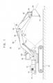
- FIG. 1 is a side view illustrating construction machinery in accordance with example embodiments.
- FIG. 2 is a block diagram illustrating a control system for construction machinery in FIG. 1 .
- construction machinery 10 may include a lower travelling body 20, an upper swinging body 30 mounted to be capable of swinging on the lower travelling body 20, and a cabin 50 and a front working device 60 installed in the upper swinging body 30.
- the lower traveling body 20 may support the upper swinging body 30 and may travel the construction machine 10 such as an excavator using power generated from an engine 110.
- the lower traveling body 20 may be a caterpillar type traveling body including a caterpillar track.
- the lower traveling body 20 may be a wheel type traveling body including traveling wheels.
- the upper swinging body 30 may have an upper frame 32 as a base, and may rotate on a plane parallel to the ground on the lower traveling body 20 to set a working direction.
- the cabin 50 may be installed on a left front side of the upper frame 32, and the working device 60 may be mounted on a front side of the upper frame 32.
- a counter weight 40 may be mounted at a rear of the upper frame 32, to stabilize the construction machine by equilibrating an external force when the construction machine performs the work of raising the load upward.
- the front working device 60 may include a boom 70, an arm 80 and a bucket 90.
- the front working device 60 may be actuated by driving actuators such as a boom cylinder 72, an arm cylinder 82 and a bucket cylinder 92.
- the boom cylinder 72 for controlling a movement of the boom 70 may be installed between the boom 70 and the upper swinging body 30.
- the arm cylinder 82 for controlling a movement of the arm 80 may be installed between the arm 80 and the boom 70.
- the bucket cylinder 92 for controlling a movement of the bucket 90 may be installed between the bucket 90 and the arm 80.
- a swing motor for controlling the upper swinging body 30 may be installed between the upper swinging body 30 and the lower travelling body 20.
- the boom 70, the arm 80 and the bucket 90 may implement various movements, to thereby perform various works.
- the boom cylinder 72, the arm cylinder 82 and the bucket cylinder 92 may be extended or contracted by a hydraulic oil supplied from a hydraulic pump.
- the bucket 90 various attachments may be attached to an end portion of the arm 80 according to the purpose of the work.
- the bucket may be used for excavation or ground leveling, and a breaker (not illustrated) may be used to crush rocks or the like.
- a cutter may be used to cut scrap metal or the like.
- the construction machinery may include an excavator, a wheel loader, a forklift, etc.
- an excavator a wheel loader
- a forklift a forklift
- example embodiments may be applied to the excavator.
- it may not be limited thereto, and it may be understood that example embodiments may be applied to other construction machinery such as the wheel loader, the forklift, etc.
- a control system for construction machinery may include an environment cognition system for construction machinery.
- the environment cognition system for construction machinery may include a plurality of sensors 100, 110 installed in the construction machinery, and a data processing device 200 configured to collect and process data from the sensors to provide surrounding environment data.
- the control system for the construction machine may further include a control device 300 configured to determine an area, a volume, or a path to be worked on based on the surrounding environment data, and a planning portion configured to provide topographic information of a work terrain and work information for an automated work of the construction machine.
- the environment recognition system of the construction machine may recognize a work environment and detect surrounding objects including obstacles.
- the surrounding environment recognition system for construction machinery may include various sensors having a field of view (FoV) required for each function.
- the sensors may include a first sensor 100 installed on an upper surface of the cabin 50 and a second sensor 110 installed on a lower surface of the boom 70 of the front working device 60.
- the first sensor 100 is installed on the upper surface of the cabin 50 to obtain shape information data on the ground in the front of the excavator.
- the first sensor 100 may include a LiDAR (Light Detection And Ranging) sensor.
- the LiDAR sensor may be installed on the upper surface of the cabin 50 by a bracket.
- the LiDAR sensor may scan the front ground during a driving operation and a swing operation to obtain the shape information data and output to the data processing device 200.
- the first sensor may detect an obstacle to obtain topographic shape data.
- the obtained data may be used to determine whether the unmanned automated operation can be performed or not.
- point cloud data (PCD) obtained during the driving operation and the swing operation may be collected to be used to obtain information on the surrounding terrain environment.
- the second sensor 110 is installed on the lower surface of the boom 70 to obtain shape information data in an excavation area.
- the second sensor 110 includes a LiDAR sensor.
- the LiDAR sensor may be installed on the lower surface of the boom 70 by a bracket.
- the LiDAR sensor may scan the excavation area to obtain the shape information data and to output to the data processing device 200.
- the first sensor is located on the upper surface of the cabin 50 and may maintain a measurement direction in the forward direction to have a constant field of view (FoV). Thus, coordinate calculation may be simplified. However, in a flat or slope excavation operation, the resolution of the first sensor may decrease and a measurement blind spot may occur.
- the second sensor is installed on the lower surface of the boom 70 to improve the resolution and minimize the occurrence of the blind spot in connection with the operation of the front working device 60.
- the point cloud data (PCD) acquired by the second sensor may be used for a work plan of an automated excavator such as an excavation work and a loading operation.
- FIG. 3 is a side view illustrating an installation location of a second sensor in accordance with example embodiments.
- FIG. 4 is a side view illustrating a difference in resolution according to the installation location of the second sensor.
- an installation location of a second sensor 110 may be determined in consideration of interference between a boom 70, an arm 80, and a bucket 90 and an incident angle of a laser with respect to the ground of the second sensor 110.
- the second sensor 110 is installed in a region R2 that does not overlap a trajectory of a circle Cb drawn by an end P4 of the bucket 90, with the arm 80 folded as far as possible.
- the arm 80 is folded all the way so that the possibility of interference is greatest based on the LiDAR size (thickness T).
- the trajectory Cb of a circle of a bucket tooth P4 may be drawn as the bucket 90 moves around a bucket pin P3.
- a space created between the boom 70 and the trajectory Cb of the bucket tooth P4 may be a space in which the LiDAR is to be installed. According to the size of the LiDAR, the space may be divided into a space (OR) where the interference occurs and a space where the interference does not occur.
- a surface on which the LiDAR is to be installed may be determined to be a section in which the lower surface of the boom 70 is kept flat, that is, the surface between the starting point (a) and the end point (d). If a thickness (T) of the LiDAR is determined, the intersection points (c, d) at which the trajectory Cb of the circle crosses the installation space (P) formed when the LiDAR moves along the installation surface R1 is determined. From this, an interference space OR is obtained by finding the positions of the intersection points (c, d) using the equation of the secant of the circle. Thus, the interference-free region R2 is determined as the installation area by excluding the interference space OR from the installation surface R1.
- the second sensor 110 may be installed in a region relatively close to a female pin P2 in the interference-free region R2.
- FIG. 4 represents a difference in measurement resolution with respect to a measurement target area according to the installation position of the LiDAR. Since the LiDAR detects while an internal laser module rotates, the LiDAR may obtain samples at regular angular intervals. Accordingly, as an installation angle of the LiDAR with respect to the ground decreases (as it is installed obliquely), a distance between the measured samples increases, so that the resolution may decrease.
- the resolution when the LiDAR is installed at point A relatively close to the female pin P2, the resolution can be relatively improved by acquiring 8 samples, on the other hand, when the LiDAR is installed at point B relatively close to a boom center pin P1c, the resolution may be relatively degraded by acquiring five samples.
- the LiDAR may be installed as vertically as possible. That is, the LiDAR may be installed as close to the arm 80 as possible on the installation surface R1.
- the LiDAR may be basically installed close to the arm 80, but it may be determined to move the installation position toward the boom center pin P1c according to the FOV specification of the LiDAR.
- the data processing device 200 may collect and process data from the first and second sensors to provide surrounding environment data of the construction machinery.
- the data processing device 200 may be implemented with dedicated hardware, software, and circuitry configured to perform the functions described herein.
- the data processing device may be physically implemented by electronic circuits such as logic circuits, discrete components, microprocessors, hard-wired circuits, memory elements, wiring connections, and the like.
- the data processing device 200 may process the acquired PCD information into data having surface properties. Points in the area around the excavator may be converted into data having surface properties through a post-processing operation. For example, the PCD points may be reconstructed with uniform grid spacing through interpolation, and the points may be connected in a triangular shape through a Triangulated Irregular Networks (TIN) algorithm, and each triangle may become one surface data.
- the surface data (topographic information data of an area of interest) may be used as topographic data for determining topographic characteristics and establishing an excavation plan.
- the environment recognition system for an unmanned or automated excavator may include a plurality of LiDAR sensors which are arranged to secure a required viewing angle in the process of acquiring topographic information around the excavator and implementing a function to detect surrounding objects.
- the LiDAR sensor may be arranging at an optimal position on the lower surface of the boom 70, to minimize damages of the sensor due to the movement of the front working device 60 and improve the resolution of the ground measurement to an optimal state, thereby ensuring the efficiency and accuracy of the excavation work.
Landscapes
- Engineering & Computer Science (AREA)
- Physics & Mathematics (AREA)
- Structural Engineering (AREA)
- General Engineering & Computer Science (AREA)
- Civil Engineering (AREA)
- Mining & Mineral Resources (AREA)
- Remote Sensing (AREA)
- Radar, Positioning & Navigation (AREA)
- General Physics & Mathematics (AREA)
- Computer Networks & Wireless Communication (AREA)
- Electromagnetism (AREA)
- Mechanical Engineering (AREA)
- Operation Control Of Excavators (AREA)
- Component Parts Of Construction Machinery (AREA)
Claims (4)
- Umwelterkennungssystem für eine Baumaschine (10), umfassend:einen ersten Sensor (100), der auf einer oberen Fläche einer Kabine (50) der Baumaschine (10) installiert ist, um Forminformationen über einen vorderen Boden zu erhalten; undeinen zweiten Sensor (110), der auf einer unteren Fläche eines Auslegers der Baumaschine (10) installiert ist, um Forminformationsdaten in einem Aushubbereich zu erhalten, wobei der zweite Sensor (110) in einemInstallationsbereich (R2) installiert ist, der eine Bewegungsbahn (Cb) eines Kreises, der von einem Ende (P4) einer Schaufel (90) gezogen wird, nicht überlappt, wobei ein Arm (80) so weit wie möglich eingeklappt ist,wobei der zweite Sensor (110) einen LiDAR-Sensor (Light Detection And Ranging für Lichterfassung undEntfernungsmessung) umfasst,wobei das Umgebungserkennungssystem für eine Baumaschine (10) dadurch gekennzeichnet ist, dass, wenn eine Dicke (T) des LiDAR-Sensors bestimmt wird, Schnittpunkte (c, d) bestimmt werden, an denen die Bewegungsbahn (Cb) einen Installationsraum (P) schneidet, der gebildet wird, wenn sich der LiDAR-Sensor entlang einer Installationsfläche (R1) bewegt, auf der der LiDAR-Sensor zu installieren ist, ein Interferenzraum (OR) erhalten wird, indem Positionen der Schnittpunkte (c, d) unter Verwendung einer Gleichung einer Sekante des Kreises gefunden werden, und ein interferenzfreier Bereich als der Installationsbereich (R2) bestimmt wird, indem der Interferenzraum (OR) aus dem Installationsbereich (R2) ausgeschlossen wird.
- Umwelterkennungssystem für eine Baumaschine (10) nach Anspruch 1, wobei der zweite Sensor (110) in einem Bereich relativ nahe an einem Stift (P2) des Arms (80) in dem Installationsbereich (R2) installiert ist.
- Umwelterkennungssystem für eine Baumaschine nach Anspruch 1, wobei der erste Sensor (100) einen LiDAR-Sensor umfasst.
- Umwelterkennungssystem für eine Baumaschine (10) nach Anspruch 1, ferner umfassend:
eine Datenverarbeitungsvorrichtung (200), die eingerichtet ist, um Daten von dem ersten und dem zweiten Sensor (100, 110) zu sammeln und zu verarbeiten, um Umgebungsdaten der Baumaschine (10) bereitzustellen.
Applications Claiming Priority (1)
| Application Number | Priority Date | Filing Date | Title |
|---|---|---|---|
| KR1020190148615A KR102783177B1 (ko) | 2019-11-19 | 2019-11-19 | 건설기계의 주변 환경 인지 시스템 |
Publications (2)
| Publication Number | Publication Date |
|---|---|
| EP3825477A1 EP3825477A1 (de) | 2021-05-26 |
| EP3825477B1 true EP3825477B1 (de) | 2024-02-28 |
Family
ID=73497533
Family Applications (1)
| Application Number | Title | Priority Date | Filing Date |
|---|---|---|---|
| EP20208533.8A Active EP3825477B1 (de) | 2019-11-19 | 2020-11-19 | Umgebungskognitionssystem für baumaschinen |
Country Status (3)
| Country | Link |
|---|---|
| US (1) | US12006661B2 (de) |
| EP (1) | EP3825477B1 (de) |
| KR (1) | KR102783177B1 (de) |
Families Citing this family (4)
| Publication number | Priority date | Publication date | Assignee | Title |
|---|---|---|---|---|
| US11454713B2 (en) * | 2020-02-04 | 2022-09-27 | Caterpillar Inc. | Configuration of a LIDAR sensor scan area according to a cycle segment of an operation of a machine |
| JP7662939B2 (ja) * | 2021-07-20 | 2025-04-16 | 株式会社タダノ | クレーン |
| KR20250070459A (ko) | 2023-11-13 | 2025-05-20 | (주)온브랜딩 | 중장비 안전사고 방지 시스템 |
| US20250361699A1 (en) * | 2024-05-22 | 2025-11-27 | AIM Intelligent Machines, Inc. | Autonomous Powered Earth-Moving Vehicle Control Using LiDAR Data From On-Vehicle Sensors |
Family Cites Families (6)
| Publication number | Priority date | Publication date | Assignee | Title |
|---|---|---|---|---|
| JP5759798B2 (ja) * | 2011-06-08 | 2015-08-05 | 株式会社トプコン | 建設機械制御システム |
| JP6710493B2 (ja) | 2014-06-18 | 2020-06-17 | 住友建機株式会社 | 建設機械及びショベル |
| DE102016224076A1 (de) * | 2016-12-02 | 2018-06-07 | Robert Bosch Gmbh | Verfahren und Vorrichtung zum Bestimmen einer Position eines Baggerarms mittels eines an einem Bagger angeordneten LIDAR-Systems |
| US10544567B2 (en) | 2017-12-22 | 2020-01-28 | Caterpillar Inc. | Method and system for monitoring a rotatable implement of a machine |
| WO2019189203A1 (ja) * | 2018-03-26 | 2019-10-03 | 住友建機株式会社 | ショベル |
| JP7114302B2 (ja) * | 2018-03-31 | 2022-08-08 | 住友建機株式会社 | ショベル及びショベルの管理装置 |
-
2019
- 2019-11-19 KR KR1020190148615A patent/KR102783177B1/ko active Active
-
2020
- 2020-11-19 US US16/952,541 patent/US12006661B2/en active Active
- 2020-11-19 EP EP20208533.8A patent/EP3825477B1/de active Active
Also Published As
| Publication number | Publication date |
|---|---|
| KR102783177B1 (ko) | 2025-03-19 |
| US20210148089A1 (en) | 2021-05-20 |
| EP3825477A1 (de) | 2021-05-26 |
| US12006661B2 (en) | 2024-06-11 |
| KR20210060967A (ko) | 2021-05-27 |
Similar Documents
| Publication | Publication Date | Title |
|---|---|---|
| US12006661B2 (en) | Environment cognition system for construction machinery | |
| KR102859277B1 (ko) | 건설기계의 제어 방법 및 시스템 | |
| US8315789B2 (en) | Method for planning and executing obstacle-free paths for rotating excavation machinery | |
| CN111857124A (zh) | 用于机器控制的系统和方法 | |
| KR101812127B1 (ko) | 작업 차량의 제어 시스템, 제어 방법, 및 작업 차량 | |
| US9732502B2 (en) | Excavation system providing impact detection | |
| KR101839465B1 (ko) | 작업 기계의 제어 시스템, 작업 기계 및 작업 기계의 제어 방법 | |
| US12077945B2 (en) | Operation assistance system for work machine having an extendable work area | |
| US9454147B1 (en) | Control system for a rotating machine | |
| US20240200303A1 (en) | Autonomous work excavator and operation method thereof | |
| JP2019190193A (ja) | 作業機械 | |
| JP7023813B2 (ja) | 作業機械 | |
| JP7491185B2 (ja) | 経路設定システム | |
| CN113377102A (zh) | 用于挖掘机的控制方法、处理器、装置及挖掘机 | |
| EP4222322A1 (de) | Virtuelles grenzsystem für eine arbeitsmaschine | |
| AU2021200594A1 (en) | Configuration of a lidar sensor scan area according to a cycle segment of an operation of a machine | |
| AU2023202519A1 (en) | A work machine with an adaptive control system and method for grade control | |
| US11976444B2 (en) | Work machine with grade control using external field of view system and method | |
| US20260015834A1 (en) | Calibration and setup for a machine guidance system | |
| JP7349956B2 (ja) | 施工方法及び施工システム | |
| US12223837B2 (en) | Systems and methods for detecting false positives in collision notifications | |
| AU2019240588B2 (en) | Method and system for operating implement assemblies of machines | |
| KR20210061004A (ko) | 건설기계의 주변 환경 인지 시스템 | |
| EP4545713A1 (de) | System mit einer arbeitsmaschine und verfahren zur steuerung einer arbeitsmaschine | |
| KR102707819B1 (ko) | 자율주행 굴삭기 |
Legal Events
| Date | Code | Title | Description |
|---|---|---|---|
| PUAI | Public reference made under article 153(3) epc to a published international application that has entered the european phase |
Free format text: ORIGINAL CODE: 0009012 |
|
| STAA | Information on the status of an ep patent application or granted ep patent |
Free format text: STATUS: REQUEST FOR EXAMINATION WAS MADE |
|
| 17P | Request for examination filed |
Effective date: 20201119 |
|
| AK | Designated contracting states |
Kind code of ref document: A1 Designated state(s): AL AT BE BG CH CY CZ DE DK EE ES FI FR GB GR HR HU IE IS IT LI LT LU LV MC MK MT NL NO PL PT RO RS SE SI SK SM TR |
|
| RAP3 | Party data changed (applicant data changed or rights of an application transferred) |
Owner name: HYUNDAI DOOSAN INFRACORE CO., LTD. |
|
| RBV | Designated contracting states (corrected) |
Designated state(s): AL AT BE BG CH CY CZ DE DK EE ES FI FR GB GR HR HU IE IS IT LI LT LU LV MC MK MT NL NO PL PT RO RS SE SI SK SM TR |
|
| STAA | Information on the status of an ep patent application or granted ep patent |
Free format text: STATUS: EXAMINATION IS IN PROGRESS |
|
| 17Q | First examination report despatched |
Effective date: 20230626 |
|
| GRAP | Despatch of communication of intention to grant a patent |
Free format text: ORIGINAL CODE: EPIDOSNIGR1 |
|
| STAA | Information on the status of an ep patent application or granted ep patent |
Free format text: STATUS: GRANT OF PATENT IS INTENDED |
|
| INTG | Intention to grant announced |
Effective date: 20231011 |
|
| GRAS | Grant fee paid |
Free format text: ORIGINAL CODE: EPIDOSNIGR3 |
|
| RAP3 | Party data changed (applicant data changed or rights of an application transferred) |
Owner name: HD HYUNDAI INFRACORE CO., LTD. |
|
| GRAA | (expected) grant |
Free format text: ORIGINAL CODE: 0009210 |
|
| STAA | Information on the status of an ep patent application or granted ep patent |
Free format text: STATUS: THE PATENT HAS BEEN GRANTED |
|
| AK | Designated contracting states |
Kind code of ref document: B1 Designated state(s): AL AT BE BG CH CY CZ DE DK EE ES FI FR GB GR HR HU IE IS IT LI LT LU LV MC MK MT NL NO PL PT RO RS SE SI SK SM TR |
|
| REG | Reference to a national code |
Ref country code: GB Ref legal event code: FG4D |
|
| REG | Reference to a national code |
Ref country code: CH Ref legal event code: EP |
|
| REG | Reference to a national code |
Ref country code: DE Ref legal event code: R096 Ref document number: 602020026343 Country of ref document: DE |
|
| REG | Reference to a national code |
Ref country code: IE Ref legal event code: FG4D |
|
| REG | Reference to a national code |
Ref country code: LT Ref legal event code: MG9D |
|
| PG25 | Lapsed in a contracting state [announced via postgrant information from national office to epo] |
Ref country code: IS Free format text: LAPSE BECAUSE OF FAILURE TO SUBMIT A TRANSLATION OF THE DESCRIPTION OR TO PAY THE FEE WITHIN THE PRESCRIBED TIME-LIMIT Effective date: 20240628 |
|
| REG | Reference to a national code |
Ref country code: NL Ref legal event code: MP Effective date: 20240228 |
|
| PG25 | Lapsed in a contracting state [announced via postgrant information from national office to epo] |
Ref country code: LT Free format text: LAPSE BECAUSE OF FAILURE TO SUBMIT A TRANSLATION OF THE DESCRIPTION OR TO PAY THE FEE WITHIN THE PRESCRIBED TIME-LIMIT Effective date: 20240228 |
|
| PG25 | Lapsed in a contracting state [announced via postgrant information from national office to epo] |
Ref country code: GR Free format text: LAPSE BECAUSE OF FAILURE TO SUBMIT A TRANSLATION OF THE DESCRIPTION OR TO PAY THE FEE WITHIN THE PRESCRIBED TIME-LIMIT Effective date: 20240529 |
|
| PG25 | Lapsed in a contracting state [announced via postgrant information from national office to epo] |
Ref country code: HR Free format text: LAPSE BECAUSE OF FAILURE TO SUBMIT A TRANSLATION OF THE DESCRIPTION OR TO PAY THE FEE WITHIN THE PRESCRIBED TIME-LIMIT Effective date: 20240228 Ref country code: RS Free format text: LAPSE BECAUSE OF FAILURE TO SUBMIT A TRANSLATION OF THE DESCRIPTION OR TO PAY THE FEE WITHIN THE PRESCRIBED TIME-LIMIT Effective date: 20240528 Ref country code: NL Free format text: LAPSE BECAUSE OF FAILURE TO SUBMIT A TRANSLATION OF THE DESCRIPTION OR TO PAY THE FEE WITHIN THE PRESCRIBED TIME-LIMIT Effective date: 20240228 |
|
| PG25 | Lapsed in a contracting state [announced via postgrant information from national office to epo] |
Ref country code: ES Free format text: LAPSE BECAUSE OF FAILURE TO SUBMIT A TRANSLATION OF THE DESCRIPTION OR TO PAY THE FEE WITHIN THE PRESCRIBED TIME-LIMIT Effective date: 20240228 |
|
| PG25 | Lapsed in a contracting state [announced via postgrant information from national office to epo] |
Ref country code: RS Free format text: LAPSE BECAUSE OF FAILURE TO SUBMIT A TRANSLATION OF THE DESCRIPTION OR TO PAY THE FEE WITHIN THE PRESCRIBED TIME-LIMIT Effective date: 20240528 Ref country code: NO Free format text: LAPSE BECAUSE OF FAILURE TO SUBMIT A TRANSLATION OF THE DESCRIPTION OR TO PAY THE FEE WITHIN THE PRESCRIBED TIME-LIMIT Effective date: 20240528 Ref country code: NL Free format text: LAPSE BECAUSE OF FAILURE TO SUBMIT A TRANSLATION OF THE DESCRIPTION OR TO PAY THE FEE WITHIN THE PRESCRIBED TIME-LIMIT Effective date: 20240228 Ref country code: LT Free format text: LAPSE BECAUSE OF FAILURE TO SUBMIT A TRANSLATION OF THE DESCRIPTION OR TO PAY THE FEE WITHIN THE PRESCRIBED TIME-LIMIT Effective date: 20240228 Ref country code: IS Free format text: LAPSE BECAUSE OF FAILURE TO SUBMIT A TRANSLATION OF THE DESCRIPTION OR TO PAY THE FEE WITHIN THE PRESCRIBED TIME-LIMIT Effective date: 20240628 Ref country code: HR Free format text: LAPSE BECAUSE OF FAILURE TO SUBMIT A TRANSLATION OF THE DESCRIPTION OR TO PAY THE FEE WITHIN THE PRESCRIBED TIME-LIMIT Effective date: 20240228 Ref country code: GR Free format text: LAPSE BECAUSE OF FAILURE TO SUBMIT A TRANSLATION OF THE DESCRIPTION OR TO PAY THE FEE WITHIN THE PRESCRIBED TIME-LIMIT Effective date: 20240529 Ref country code: FI Free format text: LAPSE BECAUSE OF FAILURE TO SUBMIT A TRANSLATION OF THE DESCRIPTION OR TO PAY THE FEE WITHIN THE PRESCRIBED TIME-LIMIT Effective date: 20240228 Ref country code: ES Free format text: LAPSE BECAUSE OF FAILURE TO SUBMIT A TRANSLATION OF THE DESCRIPTION OR TO PAY THE FEE WITHIN THE PRESCRIBED TIME-LIMIT Effective date: 20240228 Ref country code: BG Free format text: LAPSE BECAUSE OF FAILURE TO SUBMIT A TRANSLATION OF THE DESCRIPTION OR TO PAY THE FEE WITHIN THE PRESCRIBED TIME-LIMIT Effective date: 20240228 |
|
| PG25 | Lapsed in a contracting state [announced via postgrant information from national office to epo] |
Ref country code: PT Free format text: LAPSE BECAUSE OF FAILURE TO SUBMIT A TRANSLATION OF THE DESCRIPTION OR TO PAY THE FEE WITHIN THE PRESCRIBED TIME-LIMIT Effective date: 20240628 Ref country code: PL Free format text: LAPSE BECAUSE OF FAILURE TO SUBMIT A TRANSLATION OF THE DESCRIPTION OR TO PAY THE FEE WITHIN THE PRESCRIBED TIME-LIMIT Effective date: 20240228 |
|
| REG | Reference to a national code |
Ref country code: AT Ref legal event code: MK05 Ref document number: 1661355 Country of ref document: AT Kind code of ref document: T Effective date: 20240228 |
|
| PG25 | Lapsed in a contracting state [announced via postgrant information from national office to epo] |
Ref country code: SE Free format text: LAPSE BECAUSE OF FAILURE TO SUBMIT A TRANSLATION OF THE DESCRIPTION OR TO PAY THE FEE WITHIN THE PRESCRIBED TIME-LIMIT Effective date: 20240228 Ref country code: PT Free format text: LAPSE BECAUSE OF FAILURE TO SUBMIT A TRANSLATION OF THE DESCRIPTION OR TO PAY THE FEE WITHIN THE PRESCRIBED TIME-LIMIT Effective date: 20240628 Ref country code: PL Free format text: LAPSE BECAUSE OF FAILURE TO SUBMIT A TRANSLATION OF THE DESCRIPTION OR TO PAY THE FEE WITHIN THE PRESCRIBED TIME-LIMIT Effective date: 20240228 Ref country code: LV Free format text: LAPSE BECAUSE OF FAILURE TO SUBMIT A TRANSLATION OF THE DESCRIPTION OR TO PAY THE FEE WITHIN THE PRESCRIBED TIME-LIMIT Effective date: 20240228 |
|
| PG25 | Lapsed in a contracting state [announced via postgrant information from national office to epo] |
Ref country code: DK Free format text: LAPSE BECAUSE OF FAILURE TO SUBMIT A TRANSLATION OF THE DESCRIPTION OR TO PAY THE FEE WITHIN THE PRESCRIBED TIME-LIMIT Effective date: 20240228 |
|
| PG25 | Lapsed in a contracting state [announced via postgrant information from national office to epo] |
Ref country code: SM Free format text: LAPSE BECAUSE OF FAILURE TO SUBMIT A TRANSLATION OF THE DESCRIPTION OR TO PAY THE FEE WITHIN THE PRESCRIBED TIME-LIMIT Effective date: 20240228 |
|
| PG25 | Lapsed in a contracting state [announced via postgrant information from national office to epo] |
Ref country code: CZ Free format text: LAPSE BECAUSE OF FAILURE TO SUBMIT A TRANSLATION OF THE DESCRIPTION OR TO PAY THE FEE WITHIN THE PRESCRIBED TIME-LIMIT Effective date: 20240228 Ref country code: EE Free format text: LAPSE BECAUSE OF FAILURE TO SUBMIT A TRANSLATION OF THE DESCRIPTION OR TO PAY THE FEE WITHIN THE PRESCRIBED TIME-LIMIT Effective date: 20240228 |
|
| PG25 | Lapsed in a contracting state [announced via postgrant information from national office to epo] |
Ref country code: AT Free format text: LAPSE BECAUSE OF FAILURE TO SUBMIT A TRANSLATION OF THE DESCRIPTION OR TO PAY THE FEE WITHIN THE PRESCRIBED TIME-LIMIT Effective date: 20240228 |
|
| PG25 | Lapsed in a contracting state [announced via postgrant information from national office to epo] |
Ref country code: SK Free format text: LAPSE BECAUSE OF FAILURE TO SUBMIT A TRANSLATION OF THE DESCRIPTION OR TO PAY THE FEE WITHIN THE PRESCRIBED TIME-LIMIT Effective date: 20240228 |
|
| PG25 | Lapsed in a contracting state [announced via postgrant information from national office to epo] |
Ref country code: SM Free format text: LAPSE BECAUSE OF FAILURE TO SUBMIT A TRANSLATION OF THE DESCRIPTION OR TO PAY THE FEE WITHIN THE PRESCRIBED TIME-LIMIT Effective date: 20240228 Ref country code: SK Free format text: LAPSE BECAUSE OF FAILURE TO SUBMIT A TRANSLATION OF THE DESCRIPTION OR TO PAY THE FEE WITHIN THE PRESCRIBED TIME-LIMIT Effective date: 20240228 Ref country code: RO Free format text: LAPSE BECAUSE OF FAILURE TO SUBMIT A TRANSLATION OF THE DESCRIPTION OR TO PAY THE FEE WITHIN THE PRESCRIBED TIME-LIMIT Effective date: 20240228 Ref country code: EE Free format text: LAPSE BECAUSE OF FAILURE TO SUBMIT A TRANSLATION OF THE DESCRIPTION OR TO PAY THE FEE WITHIN THE PRESCRIBED TIME-LIMIT Effective date: 20240228 Ref country code: DK Free format text: LAPSE BECAUSE OF FAILURE TO SUBMIT A TRANSLATION OF THE DESCRIPTION OR TO PAY THE FEE WITHIN THE PRESCRIBED TIME-LIMIT Effective date: 20240228 Ref country code: CZ Free format text: LAPSE BECAUSE OF FAILURE TO SUBMIT A TRANSLATION OF THE DESCRIPTION OR TO PAY THE FEE WITHIN THE PRESCRIBED TIME-LIMIT Effective date: 20240228 Ref country code: AT Free format text: LAPSE BECAUSE OF FAILURE TO SUBMIT A TRANSLATION OF THE DESCRIPTION OR TO PAY THE FEE WITHIN THE PRESCRIBED TIME-LIMIT Effective date: 20240228 |
|
| REG | Reference to a national code |
Ref country code: DE Ref legal event code: R097 Ref document number: 602020026343 Country of ref document: DE |
|
| PG25 | Lapsed in a contracting state [announced via postgrant information from national office to epo] |
Ref country code: IT Free format text: LAPSE BECAUSE OF FAILURE TO SUBMIT A TRANSLATION OF THE DESCRIPTION OR TO PAY THE FEE WITHIN THE PRESCRIBED TIME-LIMIT Effective date: 20240228 |
|
| PG25 | Lapsed in a contracting state [announced via postgrant information from national office to epo] |
Ref country code: IT Free format text: LAPSE BECAUSE OF FAILURE TO SUBMIT A TRANSLATION OF THE DESCRIPTION OR TO PAY THE FEE WITHIN THE PRESCRIBED TIME-LIMIT Effective date: 20240228 |
|
| PLBE | No opposition filed within time limit |
Free format text: ORIGINAL CODE: 0009261 |
|
| STAA | Information on the status of an ep patent application or granted ep patent |
Free format text: STATUS: NO OPPOSITION FILED WITHIN TIME LIMIT |
|
| 26N | No opposition filed |
Effective date: 20241129 |
|
| PG25 | Lapsed in a contracting state [announced via postgrant information from national office to epo] |
Ref country code: SI Free format text: LAPSE BECAUSE OF FAILURE TO SUBMIT A TRANSLATION OF THE DESCRIPTION OR TO PAY THE FEE WITHIN THE PRESCRIBED TIME-LIMIT Effective date: 20240228 |
|
| REG | Reference to a national code |
Ref country code: CH Ref legal event code: PL |
|
| PG25 | Lapsed in a contracting state [announced via postgrant information from national office to epo] |
Ref country code: MC Free format text: LAPSE BECAUSE OF FAILURE TO SUBMIT A TRANSLATION OF THE DESCRIPTION OR TO PAY THE FEE WITHIN THE PRESCRIBED TIME-LIMIT Effective date: 20240228 |
|
| PG25 | Lapsed in a contracting state [announced via postgrant information from national office to epo] |
Ref country code: LU Free format text: LAPSE BECAUSE OF NON-PAYMENT OF DUE FEES Effective date: 20241119 |
|
| REG | Reference to a national code |
Ref country code: CH Ref legal event code: PL |
|
| PG25 | Lapsed in a contracting state [announced via postgrant information from national office to epo] |
Ref country code: CH Free format text: LAPSE BECAUSE OF NON-PAYMENT OF DUE FEES Effective date: 20241130 |
|
| REG | Reference to a national code |
Ref country code: BE Ref legal event code: MM Effective date: 20241130 |
|
| PG25 | Lapsed in a contracting state [announced via postgrant information from national office to epo] |
Ref country code: BE Free format text: LAPSE BECAUSE OF NON-PAYMENT OF DUE FEES Effective date: 20241130 |
|
| PG25 | Lapsed in a contracting state [announced via postgrant information from national office to epo] |
Ref country code: IE Free format text: LAPSE BECAUSE OF NON-PAYMENT OF DUE FEES Effective date: 20241119 |
|
| PGFP | Annual fee paid to national office [announced via postgrant information from national office to epo] |
Ref country code: DE Payment date: 20251022 Year of fee payment: 6 |
|
| PGFP | Annual fee paid to national office [announced via postgrant information from national office to epo] |
Ref country code: GB Payment date: 20251023 Year of fee payment: 6 |
|
| PGFP | Annual fee paid to national office [announced via postgrant information from national office to epo] |
Ref country code: FR Payment date: 20251023 Year of fee payment: 6 |
|
| PG25 | Lapsed in a contracting state [announced via postgrant information from national office to epo] |
Ref country code: HU Free format text: LAPSE BECAUSE OF FAILURE TO SUBMIT A TRANSLATION OF THE DESCRIPTION OR TO PAY THE FEE WITHIN THE PRESCRIBED TIME-LIMIT; INVALID AB INITIO Effective date: 20201119 |
|
| PG25 | Lapsed in a contracting state [announced via postgrant information from national office to epo] |
Ref country code: CY Free format text: LAPSE BECAUSE OF FAILURE TO SUBMIT A TRANSLATION OF THE DESCRIPTION OR TO PAY THE FEE WITHIN THE PRESCRIBED TIME-LIMIT; INVALID AB INITIO Effective date: 20201119 |