EP3825008A1 - Magnetic separator, magnetic separator control device, and magnetic sludge removal method - Google Patents
Magnetic separator, magnetic separator control device, and magnetic sludge removal method Download PDFInfo
- Publication number
- EP3825008A1 EP3825008A1 EP20204293.3A EP20204293A EP3825008A1 EP 3825008 A1 EP3825008 A1 EP 3825008A1 EP 20204293 A EP20204293 A EP 20204293A EP 3825008 A1 EP3825008 A1 EP 3825008A1
- Authority
- EP
- European Patent Office
- Prior art keywords
- magnetic
- magnetic sludge
- magnet drum
- liquid
- sludge
- Prior art date
- Legal status (The legal status is an assumption and is not a legal conclusion. Google has not performed a legal analysis and makes no representation as to the accuracy of the status listed.)
- Granted
Links
Images





Classifications
-
- B—PERFORMING OPERATIONS; TRANSPORTING
- B03—SEPARATION OF SOLID MATERIALS USING LIQUIDS OR USING PNEUMATIC TABLES OR JIGS; MAGNETIC OR ELECTROSTATIC SEPARATION OF SOLID MATERIALS FROM SOLID MATERIALS OR FLUIDS; SEPARATION BY HIGH-VOLTAGE ELECTRIC FIELDS
- B03C—MAGNETIC OR ELECTROSTATIC SEPARATION OF SOLID MATERIALS FROM SOLID MATERIALS OR FLUIDS; SEPARATION BY HIGH-VOLTAGE ELECTRIC FIELDS
- B03C1/00—Magnetic separation
- B03C1/02—Magnetic separation acting directly on the substance being separated
- B03C1/04—Magnetic separation acting directly on the substance being separated with the material carriers in the form of trays or with tables
- B03C1/08—Magnetic separation acting directly on the substance being separated with the material carriers in the form of trays or with tables with non-movable magnets
-
- B—PERFORMING OPERATIONS; TRANSPORTING
- B03—SEPARATION OF SOLID MATERIALS USING LIQUIDS OR USING PNEUMATIC TABLES OR JIGS; MAGNETIC OR ELECTROSTATIC SEPARATION OF SOLID MATERIALS FROM SOLID MATERIALS OR FLUIDS; SEPARATION BY HIGH-VOLTAGE ELECTRIC FIELDS
- B03C—MAGNETIC OR ELECTROSTATIC SEPARATION OF SOLID MATERIALS FROM SOLID MATERIALS OR FLUIDS; SEPARATION BY HIGH-VOLTAGE ELECTRIC FIELDS
- B03C1/00—Magnetic separation
- B03C1/02—Magnetic separation acting directly on the substance being separated
- B03C1/10—Magnetic separation acting directly on the substance being separated with cylindrical material carriers
- B03C1/12—Magnetic separation acting directly on the substance being separated with cylindrical material carriers with magnets moving during operation; with movable pole pieces
-
- B—PERFORMING OPERATIONS; TRANSPORTING
- B03—SEPARATION OF SOLID MATERIALS USING LIQUIDS OR USING PNEUMATIC TABLES OR JIGS; MAGNETIC OR ELECTROSTATIC SEPARATION OF SOLID MATERIALS FROM SOLID MATERIALS OR FLUIDS; SEPARATION BY HIGH-VOLTAGE ELECTRIC FIELDS
- B03C—MAGNETIC OR ELECTROSTATIC SEPARATION OF SOLID MATERIALS FROM SOLID MATERIALS OR FLUIDS; SEPARATION BY HIGH-VOLTAGE ELECTRIC FIELDS
- B03C1/00—Magnetic separation
- B03C1/02—Magnetic separation acting directly on the substance being separated
- B03C1/10—Magnetic separation acting directly on the substance being separated with cylindrical material carriers
- B03C1/14—Magnetic separation acting directly on the substance being separated with cylindrical material carriers with non-movable magnets
-
- B—PERFORMING OPERATIONS; TRANSPORTING
- B03—SEPARATION OF SOLID MATERIALS USING LIQUIDS OR USING PNEUMATIC TABLES OR JIGS; MAGNETIC OR ELECTROSTATIC SEPARATION OF SOLID MATERIALS FROM SOLID MATERIALS OR FLUIDS; SEPARATION BY HIGH-VOLTAGE ELECTRIC FIELDS
- B03C—MAGNETIC OR ELECTROSTATIC SEPARATION OF SOLID MATERIALS FROM SOLID MATERIALS OR FLUIDS; SEPARATION BY HIGH-VOLTAGE ELECTRIC FIELDS
- B03C1/00—Magnetic separation
- B03C1/02—Magnetic separation acting directly on the substance being separated
-
- B—PERFORMING OPERATIONS; TRANSPORTING
- B03—SEPARATION OF SOLID MATERIALS USING LIQUIDS OR USING PNEUMATIC TABLES OR JIGS; MAGNETIC OR ELECTROSTATIC SEPARATION OF SOLID MATERIALS FROM SOLID MATERIALS OR FLUIDS; SEPARATION BY HIGH-VOLTAGE ELECTRIC FIELDS
- B03C—MAGNETIC OR ELECTROSTATIC SEPARATION OF SOLID MATERIALS FROM SOLID MATERIALS OR FLUIDS; SEPARATION BY HIGH-VOLTAGE ELECTRIC FIELDS
- B03C1/00—Magnetic separation
- B03C1/02—Magnetic separation acting directly on the substance being separated
- B03C1/025—High gradient magnetic separators
- B03C1/031—Component parts; Auxiliary operations
- B03C1/033—Component parts; Auxiliary operations characterised by the magnetic circuit
- B03C1/0332—Component parts; Auxiliary operations characterised by the magnetic circuit using permanent magnets
-
- B—PERFORMING OPERATIONS; TRANSPORTING
- B03—SEPARATION OF SOLID MATERIALS USING LIQUIDS OR USING PNEUMATIC TABLES OR JIGS; MAGNETIC OR ELECTROSTATIC SEPARATION OF SOLID MATERIALS FROM SOLID MATERIALS OR FLUIDS; SEPARATION BY HIGH-VOLTAGE ELECTRIC FIELDS
- B03C—MAGNETIC OR ELECTROSTATIC SEPARATION OF SOLID MATERIALS FROM SOLID MATERIALS OR FLUIDS; SEPARATION BY HIGH-VOLTAGE ELECTRIC FIELDS
- B03C1/00—Magnetic separation
- B03C1/32—Magnetic separation acting on the medium containing the substance being separated, e.g. magneto-gravimetric-, magnetohydrostatic-, or magnetohydrodynamic separation
-
- B—PERFORMING OPERATIONS; TRANSPORTING
- B24—GRINDING; POLISHING
- B24B—MACHINES, DEVICES, OR PROCESSES FOR GRINDING OR POLISHING; DRESSING OR CONDITIONING OF ABRADING SURFACES; FEEDING OF GRINDING, POLISHING, OR LAPPING AGENTS
- B24B55/00—Safety devices for grinding or polishing machines; Accessories fitted to grinding or polishing machines for keeping tools or parts of the machine in good working condition
-
- B—PERFORMING OPERATIONS; TRANSPORTING
- B03—SEPARATION OF SOLID MATERIALS USING LIQUIDS OR USING PNEUMATIC TABLES OR JIGS; MAGNETIC OR ELECTROSTATIC SEPARATION OF SOLID MATERIALS FROM SOLID MATERIALS OR FLUIDS; SEPARATION BY HIGH-VOLTAGE ELECTRIC FIELDS
- B03C—MAGNETIC OR ELECTROSTATIC SEPARATION OF SOLID MATERIALS FROM SOLID MATERIALS OR FLUIDS; SEPARATION BY HIGH-VOLTAGE ELECTRIC FIELDS
- B03C2201/00—Details of magnetic or electrostatic separation
- B03C2201/18—Magnetic separation whereby the particles are suspended in a liquid
-
- B—PERFORMING OPERATIONS; TRANSPORTING
- B03—SEPARATION OF SOLID MATERIALS USING LIQUIDS OR USING PNEUMATIC TABLES OR JIGS; MAGNETIC OR ELECTROSTATIC SEPARATION OF SOLID MATERIALS FROM SOLID MATERIALS OR FLUIDS; SEPARATION BY HIGH-VOLTAGE ELECTRIC FIELDS
- B03C—MAGNETIC OR ELECTROSTATIC SEPARATION OF SOLID MATERIALS FROM SOLID MATERIALS OR FLUIDS; SEPARATION BY HIGH-VOLTAGE ELECTRIC FIELDS
- B03C2201/00—Details of magnetic or electrostatic separation
- B03C2201/24—Details of magnetic or electrostatic separation for measuring or calculating of parameters, e.g. efficiency
-
- Y—GENERAL TAGGING OF NEW TECHNOLOGICAL DEVELOPMENTS; GENERAL TAGGING OF CROSS-SECTIONAL TECHNOLOGIES SPANNING OVER SEVERAL SECTIONS OF THE IPC; TECHNICAL SUBJECTS COVERED BY FORMER USPC CROSS-REFERENCE ART COLLECTIONS [XRACs] AND DIGESTS
- Y02—TECHNOLOGIES OR APPLICATIONS FOR MITIGATION OR ADAPTATION AGAINST CLIMATE CHANGE
- Y02P—CLIMATE CHANGE MITIGATION TECHNOLOGIES IN THE PRODUCTION OR PROCESSING OF GOODS
- Y02P70/00—Climate change mitigation technologies in the production process for final industrial or consumer products
- Y02P70/10—Greenhouse gas [GHG] capture, material saving, heat recovery or other energy efficient measures, e.g. motor control, characterised by manufacturing processes, e.g. for rolling metal or metal working
Definitions
- Certain embodiments of the present invention relate to a magnetic separator, a magnetic separator control device, and a magnetic sludge removal method.
- Magnetic separators are known as devices that remove a magnetic sludge from a liquid to be treated containing the magnetic sludge (Japanese Unexamined Patent Publication No. 9-1176 and Japanese Unexamined Patent Publication No. 2018-89560 ).
- a part of a rotating magnet drum is immersed in the liquid to be treated, and the magnetic sludge in the liquid to be treated is attracted to an outer peripheral surface of the magnet drum by a magnetic force.
- the magnetic sludge attracted on the outer peripheral surface is separated from the liquid to be treated as the magnet drum rotates.
- the magnetic sludge attracted on the outer peripheral surface of the magnet drum is separated from the liquid to be treated, and then scraped off from the outer peripheral surface of the magnet drum by a scraper or the like and discharged to the outside.
- An object of the present invention is to provide a magnetic separator in which even when the content of a magnetic sludge in a liquid to be treated increases or decreases, the recovery performance of the magnetic sludge is less likely to degrade and a malfunction of the device is less likely to occur.
- Another object of the present invention relates to a magnetic separator control device that controls the magnetic separator.
- Still another object of the present invention is to provide a magnetic sludge removal method in which even when the content of the magnetic sludge in the liquid to be treated increases or decreases, the recovery performance of the magnetic sludge is less likely to degrade and a malfunction of the device is less likely to occur.
- a magnetic separator including a magnet drum that rotates in a state in which a part of an outer peripheral surface is immersed in a flow of a liquid to be treated containing a magnetic sludge and a magnetic force is generated on the outer peripheral surface; a removing mechanism that removes the magnetic sludge on the outer peripheral surface of the magnet drum from the outer peripheral surface of the magnet drum; a magnetic sludge containing information acquisition device that acquires magnetic sludge containing information relating to a content of the magnetic sludge contained in the liquid to be treated; and a control device that changes a magnetic sludge removal capability of the magnet drum depending on the magnetic sludge containing information acquired by the magnetic sludge containing information acquisition device.
- a magnetic separator control device that acquires magnetic sludge containing information related to a content of a magnetic sludge contained in a liquid to be treated flowing into a magnetic separator and changes amagnetic sludge removal capability of the magnetic separator depending on the acquired magnetic sludge containing information.
- a magnetic sludge removal method including:
- the magnetic sludge removal capability of the magnet drum By changing the magnetic sludge removal capability of the magnet drum depending on the c magnetic sludge containing information, it is possible to suppress a decrease in the recovery performance of the magnetic sludge.
- the removal capability is enhanced as the magnetic sludge content increases, the malfunction of the device is less likely to occur due to the attraction of a large amount of magnetic sludge to the magnet drum.
- a magnetic separator according to an embodiment will be described with reference to Figs. 1 to 3 .
- FIG. 1 is a schematic view of the magnetic separator according to the embodiment.
- a flowpath 32 through which a liquid to be treated 30 containing a magnetic sludge 31 flows is defined in a housing 10.
- the housing 10 includes an inflow port 11 into which the liquid to be treated 30 flows, and a discharge port 12 from which the liquid to be treated 30 is discharged.
- the magnet drum 20 is disposed in the housing 10. When the liquid to be treated 30 reaches a downstream end of the flow path 32, the liquid to be treated is discharged to the outside from the discharge port 12.
- the magnet drum 20 has a central axis parallel to the liquid surface of the liquid to be treated 30 and is supported in the housing 10 in a posture orthogonal to a flow direction of the liquid to be treated 30.
- the magnet drum 20 has an outer cylinder 21 and an inner cylinder 22. A portion of an outer peripheral surface of the outer cylinder 21 in a circumferential direction, for example, a substantially lower half circumference is immersed in the liquid to be treated 30.
- the outer cylinder 21 is rotated around the central axis by a motor 25.
- a driving force is transmitted from the motor 25 to the outer cylinder 21 by, for example, a sprocket and a chain.
- Amovement direction (peripheral speed direction) of the outer peripheral surface of the outer cylinder 21 is opposite to the flow direction of the liquid to be treated 30.
- the inner cylinder 22 is fixed to the housing 10 and does not rotate, and a plurality of magnets 23 are disposed side by side in the circumferential direction on an outer peripheral surface of the inner cylinder 22.
- Each of the magnets 23 is disposed such that magnetic poles having different polarities appear on a surface on an inner peripheral side thereof and a surface on an outer peripheral side thereof and S poles and N poles appear alternately in the circumferential direction.
- the magnet 23 is disposed in a region immersed in the liquid to be treated 30 and a region ranging from the immersed region to a top portion of the inner cylinder 22 in the peripheral speed direction of the outer peripheral surface of the outer cylinder 21 in the circumferential direction.
- the plurality of magnets 23 generate magnetic flux on the outer peripheral surface of the outer cylinder 21. Due to this magnetic flux, the magnetic sludge 31 is attracted to the outer peripheral surface of the outer cylinder 21.
- a part of the bottom surface of the flow path 32 of the liquid to be treated 30 has a shape that reflects the outer peripheral surface of the outer cylinder 21 such that the radial dimension from the outer peripheral surface of the outer cylinder 21 to a bottom surface of the flow path 32 falls within a predetermined range.
- a scraper 26 is in contact with an outer peripheral surface of the magnet drum 20 at a position advanced about 1/8 lap in the peripheral speed direction from the top portion of the magnet drum 20.
- the magnet 23 is not disposed at the point of the outer peripheral surface of the magnet drum 20 where the scraper 26 is in contact.
- the scraper 26 functions as a removing mechanism for scraping the magnetic sludge 31 on the outer peripheral surface of the magnet drum 20 from the outer peripheral surface.
- the magnetic sludge 31 scraped off by the scraper 26 is recovered in a recovery container 29 through the discharge path 28.
- a roller 27 is pressed against the outer peripheral surface of the magnet drum 20 at a position from a contact point between the outer peripheral surface of the magnet drum 20 and the liquid surface of the liquid to be treated 30 to the top portion of the outer peripheral surface in the peripheral speed direction.
- the roller 27 rotates in a direction opposite to a rotational direction of the outer cylinder 21 by transmitting power from a rotary shaft of the outer cylinder 21 via the sprocket and the chain.
- An elastic body is disposed on an outer peripheral surface of the roller 27.
- a pump 40 sends the liquid to be treated 30 containing the magnetic sludge 31 to the inflow port 11 of the housing 10.
- a branch flow path 42 branches from a main flow path 41 ranging from the pump 40 to the inflow port 11 and then joins the main flow path 41.
- a detector 43 is inserted in the branch flow path 42. The detector 43 measures the content of the magnetic sludge 31 contained in the liquid to be treated 30 flowing through the branch flow path 42. As the detector 43, for example, a suspended substance concentration meter using a laser can be used. The detector 43 can measure the weight concentration, volume concentration, number of particles per unit volume, or the like of the magnetic sludge as the "magnetic sludge content".
- the content of the magnetic sludge 31 of the liquid to be treated 30 flowing through the main flow path 41 is substantially the same as the content of the magnetic sludge 31 of the liquid to be treated 30 flowing through the branch flow path 42.
- the detector 43 functions as a "magnetic sludge containing information acquisition device" that measures the magnetic sludge content of the liquid to be treated 30.
- a measured value of the content of the magnetic sludge 31 is input to the control device 50.
- the control device 50 includes a sequencer 51 and an inverter 52.
- the sequencer 51 controls the inverter 52 such that the magnet drum 20 rotates at a preferable rotational speed according to the measured value of the content of the magnetic sludge 31.
- the inverter 52 supplies driving power to the motor 25. That is, the control device 50 controls the rotational speed of the magnet drum 20 depending on the content of the magnetic sludge 31 contained in the liquid to be treated 30.
- Fig. 2 is a graph illustrating an example of a relationship between a measured value of the content of the magnetic sludge 31 and a target value of the rotational speed of the magnet drum 20.
- a horizontal axis represents the measured value of the content of the magnetic sludge 31, and a vertical axis represents the target value of the rotational speed of the magnet drum 20.
- the target value of the rotational speed of the magnet drum 20 is determined such that the thickness of the magnetic sludge 31 attracted on the outer peripheral surface of the magnet drum 20 falls within a target range, at the position where the roller 27 ( Fig. 1 ) is in contact.
- the target range of the thickness of the magnetic sludge 31 is, for example, 0.5 mm or more and 1 mm or less.
- the target value of the rotational speed of the magnet drum 20 is set to zero. That is, when the measured value of the content of the magnetic sludge 31 becomes less than the reference lower limit value C1, the rotation of the magnet drum 20 is stopped. When the measured value of the content of the magnetic sludge 31 becomes the rotation start threshold value C2 or more, the rotation of the magnet drum 20 is resumed. When the measured value of the content of the magnetic sludge 31 exceeds the reference upper limit value C3, the target value of the rotational speed of the magnet drum 20 is maintained at a rotational speed corresponding to the maximum allowable rotational speed of the motor 25.
- Fig. 3 is a graph illustrating time changes in the target value of the rotational speed of the magnet drum 20 during a period in which the measured value of the content of the magnetic sludge 31 is below the reference lower limit value C1 ( Fig. 2 ) .
- the control device 50 intermittently rotates the magnet drum 20 during the period until the measured value of the content of the magnetic sludge 31 becomes a rotation start threshold value C2 or more.
- the magnet drum 20 is rotated at least once whenever a certain cycle T elapses.
- the amount of the magnetic sludge 31 attracted on the outer peripheral surface of the magnet drum 20 increases when the content of the magnetic sludge 31 increases.
- a magnetic force for attracting the magnetic sludge 31 weakens.
- the amount of magnetic sludge 31 that is not attracted to the magnet drum 20 and is discharged from the discharge port 12 increases. That is, the removal capability of the magnetic sludge 31 decreases.
- the magnetic sludge 31 attracted on the outer peripheral surface of the magnet drum 20 is removed at an early stage by increasing the rotational speed of the magnet drum 20.
- a decrease in attraction force due to the excessive magnetic sludge 31 being attracted to the outer peripheral surface of the magnet drum 20 is suppressed.
- the rotation of the magnet drum 20 is stopped. Therefore, the amount of energy consumption can be suppressed.
- the magnetic sludge 31 is gradually attracted on the outer peripheral surface of the magnet drum 20, and the layer of the magnetic sludge 31 becomes thick.
- the magnet drum 20 is intermittently rotated even during the period in which the content of the magnetic sludge 31 is less than the reference lower limit value C1, it is possible to suppress a situation in which the layer of the magnetic sludge 31 attracted on the outer peripheral surface of the magnet drum 20 becomes excessively thicker.
- the target value of the rotational speed of the magnet drum 20 is constant in a range where the magnetic sludge content exceeds the reference upper limit value C3 ( Fig. 2 ). For this reason, a state in which the layer of the magnetic sludge attracted on the outer peripheral surface of the magnet drum 20 becomes excessively thick may occur.
- the magnetic sludge content exceeds the reference upper limit value C3 ( Fig. 2 )
- the pressing force of the roller 27 ( Fig. 1 ) against the magnet drum 20 is reduced. Accordingly, an excessive increase in the load applied to the motor 25 can be suppressed. Accordingly, the risk of failure of the drive system such as the motor 25 can be further reduced.
- roller 27 power is transmitted to the roller 27 ( Fig. 1 ) by using the sprocket and the chain to forcibly rotate the roller 27.
- the roller 27 may be configured to be rotated by a frictional force between the outer cylinder 21 and the roller 27.
- the grinding system according to the present embodiment includes a grinding device, and the magnetic separator according to the embodiment illustrated in Figs. 1 to 3 .
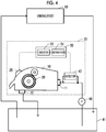
- Fig. 4 is a schematic view of the grinding system according to the present embodiment.
- the grinding device 60 grinds a workpiece containing a magnetic material with a grindstone while supplying a coolant liquid.
- the coolant liquid containing the magnetic sludge discharged from the grinding device 60 is recovered in the coolant tank 61.
- the pump 40 suctions the coolant liquid containing the magnetic sludge from the coolant tank 61 and supplies the coolant liquid to the magnetic separator 15.
- This coolant liquid corresponds to the liquid to be treated supplied to the magnetic separator illustrated in Figs. 1 to 3 .
- the coolant liquid from which the magnetic sludge has been removed by the magnetic separator 15 is discharged from the discharge port 12 and returned to the coolant tank 61.
- the coolant liquid is supplied from the coolant tank 61 to the grinding device 60 and reused.
- the magnetic sludge By operating the magnetic separator 15, the magnetic sludge can be removed from the coolant liquid in the coolant tank 61.
- the coolant liquid from which the magnetic sludge has been removed can be supplied to the grinding device 60.
- the rotational speed of the magnet drum 20 ( Fig. 1 ) depending on the magnetic sludge content of the coolant liquid suctioned by the pump 40, when the magnetic sludge content of the coolant liquid in the coolant tank 61 increases, the rotational speed of the magnet drum 20 increases, and the magnetic sludge removal capability increases. As a result, the magnetic sludge content of the coolant liquid in the coolant tank 61 can be rapidly decreased.
- the grinding system according to the present embodiment includes a grinding device, and the magnetic separator according to the embodiment illustrated in Figs. 1 to 3 .
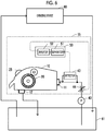
- Fig. 5 is a schematic view of the grinding system according to the present embodiment.
- the coolant liquid containing the magnetic sludge discharged from the grinding device 60 flows into the inflow port 11 of the magnetic separator 15 via the pump 40.
- the coolant liquid discharged from the discharge port 12 is recovered in a buffer tank 62.
- the coolant liquid recovered in the buffer tank 62 is supplied to the grinding device 60 and reused.
- the magnetic sludge removal capability of the magnetic separator 15 can be increased or decreased on the basis of the magnetic sludge content of the coolant liquid discharged from the grinding device 60. Accordingly, it is possible to exhibit sufficient magnetic sludge removal capability and resupply the coolant liquid, from which the magnetic sludge has been sufficiently removed, to the grinding device 60.
- Fig. 6 is a schematic view of the magnetic separator according to the present embodiment, and the grinding device.
- the coolant liquid discharged from the grinding device 60 is recovered in the coolant tank 61, and the coolant liquid in the coolant tank 61 is resupplied to the grinding device 60.
- a flow rate adjusting valve 44 is inserted into a flow path from the discharge port of the pump 40 to the inflow port 11 of the magnetic separator 15.
- the rotational speed of the motor 25 is adjusted depending on the magnetic sludge content of the coolant liquid.
- the control device 50 is adjusted depending on the magnetic sludge content of the coolant liquid, so that the flow rate adjusting valve 44 controls the flow rate of the coolant liquid flowing into the inflow port 11 of the magnetic separator 15.
- Fig. 7 is a graph illustrating a relationship between a measured value of the magnetic sludge content of the coolant liquid and a target value of the flow rate of the coolant liquid.
- a horizontal axis represents the measured value of the magnetic sludge content
- a vertical axis represents the target value of the flow rate of the coolant liquid.
- the control device 50 lowers the target value of the flow rate of the coolant liquid as the measured value of the magnetic sludge content increases. For example, when the measured value of the magnetic sludge content increases from C4 to C5, the control device 50 lowers the target value of the flow rate of the coolant liquid from F2 to F1.
- the control device 50 increases the target value of the flow rate of the coolant liquid from F1 to F2.
- the control device 50 sets the target value of the flow rate of the coolant liquid to zero. That is, the pump 40 is stopped.
- Fig. 8 is a schematic view of the magnetic separator according to the present embodiment, and the grinding device.
- the coolant liquid discharged from the grinding device 60 flows into the inflow port 11 of the magnetic separator 15 through the pump 40.
- the measured value of the magnetic sludge content of the liquid to be treated detected by the detector 43 is input to the control device 50.
- the grinding conditions of the grinding device 60 are input to the control device 50 from an output unit 45 of the grinding device 60.
- the grinding conditions include, for example, the grinding depth of the grindstone into the workpiece, the movement speed of the workpiece, and the like.
- the output unit 45 has a function as a magnetic sludge containing information acquisition unit.
- the control device 50 determines the target value of the rotational speed of the magnet drum 20 depending on the grinding conditions of the grinding device 60.
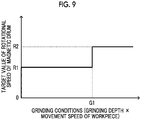
- Fig. 9 is a graph illustrating an example of a relationship between the grinding conditions and the target value of the rotational speed of the magnet drum 20.
- a horizontal axis represents the product of the grinding depth of the grindstone and the movement speed of the workpiece, and a vertical axis represents the target value of the rotational speed of the magnet drum 20.
- the amount of magnetic sludge generated increases as the grinding depth of the grindstone increases, and the amount of magnetic sludge generated per unit time increases as the movement speed of the workpiece increases. That is, a large product of the grinding depth of the grindstone and the movement speed of the workpiece means that the magnetic sludge content of the coolant liquid increases.
- the control device 50 sets the target value of the rotational speed of the magnet drum 20 to R1.
- the target value of the rotational speed of the magnet drum 20 is raised from R1 to R2.
- the rotation of the magnet drum 20 is stopped by setting the target value of the rotational speed of the magnet drum 20 to zero.
- the drum type magnetic separator having the magnet drum has been exemplified.
- the technical idea of changing the magnetic sludge removal capability depending on the content of the magnetic sludge can also be applied a magnetic separator having another structure, for example, a conveyor type magnetic separator.
Landscapes
- Physics & Mathematics (AREA)
- Fluid Mechanics (AREA)
- Engineering & Computer Science (AREA)
- Mechanical Engineering (AREA)
- Grinding-Machine Dressing And Accessory Apparatuses (AREA)
- Auxiliary Devices For Machine Tools (AREA)
Abstract
Description
- Certain embodiments of the present invention relate to a magnetic separator, a magnetic separator control device, and a magnetic sludge removal method.
- Magnetic separators are known as devices that remove a magnetic sludge from a liquid to be treated containing the magnetic sludge (Japanese Unexamined Patent Publication No.
9-1176 2018-89560 - When the content of the magnetic sludge contained in the liquid to be treated increases, there is a case where the recovery performance of the magnetic sludge degrades or a malfunction of the device caused by the attraction of a large amount of magnetic sludge on the magnet drum occurs. An object of the present invention is to provide a magnetic separator in which even when the content of a magnetic sludge in a liquid to be treated increases or decreases, the recovery performance of the magnetic sludge is less likely to degrade and a malfunction of the device is less likely to occur. Another object of the present invention relates to a magnetic separator control device that controls the magnetic separator. Still another object of the present invention is to provide a magnetic sludge removal method in which even when the content of the magnetic sludge in the liquid to be treated increases or decreases, the recovery performance of the magnetic sludge is less likely to degrade and a malfunction of the device is less likely to occur.
- According to one aspect of the present invention, there is a provided a magnetic separator including
a magnet drum that rotates in a state in which a part of an outer peripheral surface is immersed in a flow of a liquid to be treated containing a magnetic sludge and a magnetic force is generated on the outer peripheral surface;
a removing mechanism that removes the magnetic sludge on the outer peripheral surface of the magnet drum from the outer peripheral surface of the magnet drum;
a magnetic sludge containing information acquisition device that acquires magnetic sludge containing information relating to a content of the magnetic sludge contained in the liquid to be treated; and
a control device that changes a magnetic sludge removal capability of the magnet drum depending on the magnetic sludge containing information acquired by the magnetic sludge containing information acquisition device. - According to another aspect of the present invention, there is provided a magnetic separator control device that
acquires magnetic sludge containing information related to a content of a magnetic sludge contained in a liquid to be treated flowing into a magnetic separator and
changes amagnetic sludge removal capability of the magnetic separator depending on the acquired magnetic sludge containing information. - According to yet another aspect of the present invention, there is provided a magnetic sludge removal method including:
- acquires magnetic sludge containing information related to a content of a magnetic sludge contained in a liquid to be treated flowing into a magnetic separator and
- changing a magnetic sludge removal capability of the magnetic separator depending on the acquired magnetic sludge containing information.
- By changing the magnetic sludge removal capability of the magnet drum depending on the c magnetic sludge containing information, it is possible to suppress a decrease in the recovery performance of the magnetic sludge. When the removal capability is enhanced as the magnetic sludge content increases, the malfunction of the device is less likely to occur due to the attraction of a large amount of magnetic sludge to the magnet drum.
-
-
Fig. 1 is a schematic view of a magnetic separator according to an embodiment. -
Fig. 2 is a graph illustrating an example of a relationship between a measured value of the content of a magnetic sludge and a target value of the rotational speed of a magnet drum. -
Fig. 3 is a graph illustrating time changes in the target value of the rotational speed of the magnet drum during a period in which the measured value of the content of the magnetic sludge is below a reference lower limit value. -
Fig. 4 is a schematic view of a grinding system according to another embodiment. -
Fig. 5 is a schematic view of a grinding system according to still another embodiment. -
Fig. 6 is a schematic view of a magnetic separator according to still another embodiment, and a grinding device. -
Fig. 7 is a graph illustrating a relationship between a measured value of the magnetic sludge content of a coolant liquid and a target value of the flow rate of the coolant liquid. -
Fig. 8 is a schematic view of a magnetic separator according to still another embodiment, and the grinding device. -
Fig. 9 is a graph illustrating an example of a relationship between the grinding conditions and the target value of the rotational speed of the magnet drum. - A magnetic separator according to an embodiment will be described with reference to
Figs. 1 to 3 . -
Fig. 1 is a schematic view of the magnetic separator according to the embodiment. Aflowpath 32 through which a liquid to be treated 30 containing amagnetic sludge 31 flows is defined in ahousing 10. Thehousing 10 includes aninflow port 11 into which the liquid to be treated 30 flows, and adischarge port 12 from which the liquid to be treated 30 is discharged. Themagnet drum 20 is disposed in thehousing 10. When the liquid to be treated 30 reaches a downstream end of theflow path 32, the liquid to be treated is discharged to the outside from thedischarge port 12. - The
magnet drum 20 has a central axis parallel to the liquid surface of the liquid to be treated 30 and is supported in thehousing 10 in a posture orthogonal to a flow direction of the liquid to be treated 30. Themagnet drum 20 has anouter cylinder 21 and aninner cylinder 22. A portion of an outer peripheral surface of theouter cylinder 21 in a circumferential direction, for example, a substantially lower half circumference is immersed in the liquid to be treated 30. Theouter cylinder 21 is rotated around the central axis by amotor 25. A driving force is transmitted from themotor 25 to theouter cylinder 21 by, for example, a sprocket and a chain. Amovement direction (peripheral speed direction) of the outer peripheral surface of theouter cylinder 21 is opposite to the flow direction of the liquid to be treated 30. - The
inner cylinder 22 is fixed to thehousing 10 and does not rotate, and a plurality ofmagnets 23 are disposed side by side in the circumferential direction on an outer peripheral surface of theinner cylinder 22. Each of themagnets 23 is disposed such that magnetic poles having different polarities appear on a surface on an inner peripheral side thereof and a surface on an outer peripheral side thereof and S poles and N poles appear alternately in the circumferential direction. Additionally, themagnet 23 is disposed in a region immersed in the liquid to be treated 30 and a region ranging from the immersed region to a top portion of theinner cylinder 22 in the peripheral speed direction of the outer peripheral surface of theouter cylinder 21 in the circumferential direction. The plurality ofmagnets 23 generate magnetic flux on the outer peripheral surface of theouter cylinder 21. Due to this magnetic flux, themagnetic sludge 31 is attracted to the outer peripheral surface of theouter cylinder 21. - A part of the bottom surface of the
flow path 32 of the liquid to be treated 30 has a shape that reflects the outer peripheral surface of theouter cylinder 21 such that the radial dimension from the outer peripheral surface of theouter cylinder 21 to a bottom surface of theflow path 32 falls within a predetermined range. When the liquid to be treated 30 flows in the vicinity of the outer peripheral surface of theouter cylinder 21, themagnetic sludge 31 is attracted to the outer peripheral surface of theouter cylinder 21 by the magnetic force of themagnet 23. The attractedmagnetic sludge 31 moves with the rotation of theouter cylinder 21 and is separated from the liquid to be treated 30 by moving above the liquid surface of the liquid to be treated 30. - A
scraper 26 is in contact with an outer peripheral surface of themagnet drum 20 at a position advanced about 1/8 lap in the peripheral speed direction from the top portion of themagnet drum 20. Themagnet 23 is not disposed at the point of the outer peripheral surface of themagnet drum 20 where thescraper 26 is in contact. Thescraper 26 functions as a removing mechanism for scraping themagnetic sludge 31 on the outer peripheral surface of themagnet drum 20 from the outer peripheral surface. Themagnetic sludge 31 scraped off by thescraper 26 is recovered in arecovery container 29 through thedischarge path 28. - A
roller 27 is pressed against the outer peripheral surface of themagnet drum 20 at a position from a contact point between the outer peripheral surface of themagnet drum 20 and the liquid surface of the liquid to be treated 30 to the top portion of the outer peripheral surface in the peripheral speed direction. Theroller 27 rotates in a direction opposite to a rotational direction of theouter cylinder 21 by transmitting power from a rotary shaft of theouter cylinder 21 via the sprocket and the chain. An elastic body is disposed on an outer peripheral surface of theroller 27. When themagnetic sludge 31 attracted on the outer peripheral surface of themagnet drum 20 passes between theouter cylinder 21 and theroller 27, a liquid component adhering to the outer peripheral surface of theouter cylinder 21 is removed. Accordingly, themagnetic sludge 31 having a low liquid component can be separated and recovered. - A
pump 40 sends the liquid to be treated 30 containing themagnetic sludge 31 to theinflow port 11 of thehousing 10. Abranch flow path 42 branches from amain flow path 41 ranging from thepump 40 to theinflow port 11 and then joins themain flow path 41. Adetector 43 is inserted in thebranch flow path 42. Thedetector 43 measures the content of themagnetic sludge 31 contained in the liquid to be treated 30 flowing through thebranch flow path 42. As thedetector 43, for example, a suspended substance concentration meter using a laser can be used. Thedetector 43 can measure the weight concentration, volume concentration, number of particles per unit volume, or the like of the magnetic sludge as the "magnetic sludge content". The content of themagnetic sludge 31 of the liquid to be treated 30 flowing through themain flow path 41 is substantially the same as the content of themagnetic sludge 31 of the liquid to be treated 30 flowing through thebranch flow path 42. Thedetector 43 functions as a "magnetic sludge containing information acquisition device" that measures the magnetic sludge content of the liquid to be treated 30. - A measured value of the content of the
magnetic sludge 31 is input to thecontrol device 50. Thecontrol device 50 includes asequencer 51 and aninverter 52. Thesequencer 51 controls theinverter 52 such that themagnet drum 20 rotates at a preferable rotational speed according to the measured value of the content of themagnetic sludge 31. Theinverter 52 supplies driving power to themotor 25. That is, thecontrol device 50 controls the rotational speed of themagnet drum 20 depending on the content of themagnetic sludge 31 contained in the liquid to be treated 30. -
Fig. 2 is a graph illustrating an example of a relationship between a measured value of the content of themagnetic sludge 31 and a target value of the rotational speed of themagnet drum 20. A horizontal axis represents the measured value of the content of themagnetic sludge 31, and a vertical axis represents the target value of the rotational speed of themagnet drum 20. When the measured value of the content of themagnetic sludge 31 is within the range from a reference lower limit value C1 to a reference upper limit value C3, thecontrol device 50 increases the target value of the rotational speed of themagnet drum 20 as the measured value of the content of themagnetic sludge 31 rises. For example, the target value of the rotational speed of themagnet drum 20 is determined such that the thickness of themagnetic sludge 31 attracted on the outer peripheral surface of themagnet drum 20 falls within a target range, at the position where the roller 27 (Fig. 1 ) is in contact. The target range of the thickness of themagnetic sludge 31 is, for example, 0.5 mm or more and 1 mm or less. - When the measured value of the content of the
magnetic sludge 31 becomes less than the reference lower limit value C1, the target value of the rotational speed of themagnet drum 20 is set to zero. That is, when the measured value of the content of themagnetic sludge 31 becomes less than the reference lower limit value C1, the rotation of themagnet drum 20 is stopped. When the measured value of the content of themagnetic sludge 31 becomes the rotation start threshold value C2 or more, the rotation of themagnet drum 20 is resumed. When the measured value of the content of themagnetic sludge 31 exceeds the reference upper limit value C3, the target value of the rotational speed of themagnet drum 20 is maintained at a rotational speed corresponding to the maximum allowable rotational speed of themotor 25. -
Fig. 3 is a graph illustrating time changes in the target value of the rotational speed of themagnet drum 20 during a period in which the measured value of the content of themagnetic sludge 31 is below the reference lower limit value C1 (Fig. 2 ) . When the measured value of the content of themagnetic sludge 31 becomes less than the reference lower limit value C1 (Fig. 2 ) at time t1, the rotation of themagnet drum 20 is stopped. After that, thecontrol device 50 intermittently rotates themagnet drum 20 during the period until the measured value of the content of themagnetic sludge 31 becomes a rotation start threshold value C2 or more. For example, themagnet drum 20 is rotated at least once whenever a certain cycle T elapses. - Next, the excellent effects of the embodiment illustrated in
Figs. 1 to 3 will be described. - In a case where the
magnet drum 20 is rotated at a certain speed regardless of the content of themagnetic sludge 31, the amount of themagnetic sludge 31 attracted on the outer peripheral surface of themagnet drum 20 increases when the content of themagnetic sludge 31 increases. When the layer of themagnetic sludge 31 attracted on the outer peripheral surface of themagnet drum 20 becomes thicker, a magnetic force for attracting themagnetic sludge 31 weakens. As a result, the amount ofmagnetic sludge 31 that is not attracted to themagnet drum 20 and is discharged from thedischarge port 12 increases. That is, the removal capability of themagnetic sludge 31 decreases. - Additionally, when the layer of the
magnetic sludge 31 attracted on the outer peripheral surface of themagnet drum 20 becomes thicker, the liquid component removal capability by the roller 27 (Fig. 1 ) is insufficient with respect to the amount of the liquid component adhering to the outer peripheral surface of themagnet drum 20. As a result, a large amount of liquid component passes through theroller 27 and reaches the scraper 26 (Fig. 1 ), and a large amount of liquid component is discharged together with themagnetic sludge 31. - When the layer of the
magnetic sludge 31 attracted on the outer peripheral surface of themagnet drum 20 becomes thicker, an excessive load is applied to themagnet drum 20 and theroller 27. The excessive load causes a failure of a drive system such as themotor 25. - In the present embodiment, as the content of the
magnetic sludge 31 is increased, themagnetic sludge 31 attracted on the outer peripheral surface of themagnet drum 20 is removed at an early stage by increasing the rotational speed of themagnet drum 20. As a result, a decrease in attraction force due to the excessivemagnetic sludge 31 being attracted to the outer peripheral surface of themagnet drum 20 is suppressed. For this reason, it is possible to prevent a decrease in the removal capability of themagnetic sludge 31. Moreover, it is possible to obtain excellent effects of suppressing an increase in the liquid component discharged together with themagnetic sludge 31 and reducing the risk of failure of the drive system. - Moreover, when the content of the
magnetic sludge 31 becomes less than the reference lower limit value C1 (Fig. 2 ), the rotation of themagnet drum 20 is stopped. Therefore, the amount of energy consumption can be suppressed. In addition, even in a case where the content of themagnetic sludge 31 is less than the reference lower limit value C1, when a very small amount of themagnetic sludge 31 is contained, themagnetic sludge 31 is gradually attracted on the outer peripheral surface of themagnet drum 20, and the layer of themagnetic sludge 31 becomes thick. In the present embodiment, since themagnet drum 20 is intermittently rotated even during the period in which the content of themagnetic sludge 31 is less than the reference lower limit value C1, it is possible to suppress a situation in which the layer of themagnetic sludge 31 attracted on the outer peripheral surface of themagnet drum 20 becomes excessively thicker. - Next, a modification example of the embodiment illustrated in
Figs. 1 to 3 will be described. - In the embodiment illustrated in
Figs. 1 to 3 , the target value of the rotational speed of themagnet drum 20 is constant in a range where the magnetic sludge content exceeds the reference upper limit value C3 (Fig. 2 ). For this reason, a state in which the layer of the magnetic sludge attracted on the outer peripheral surface of themagnet drum 20 becomes excessively thick may occur. In the present modification example, when the magnetic sludge content exceeds the reference upper limit value C3 (Fig. 2 ), the pressing force of the roller 27 (Fig. 1 ) against themagnet drum 20 is reduced. Accordingly, an excessive increase in the load applied to themotor 25 can be suppressed. Accordingly, the risk of failure of the drive system such as themotor 25 can be further reduced. - Additionally, in the above embodiment, power is transmitted to the roller 27 (
Fig. 1 ) by using the sprocket and the chain to forcibly rotate theroller 27. Instead of transmitting the power to theroller 27, theroller 27 may be configured to be rotated by a frictional force between theouter cylinder 21 and theroller 27. - Next, a grinding system according to another embodiment will be described with reference to
Fig. 4 . The grinding system according to the present embodiment includes a grinding device, and the magnetic separator according to the embodiment illustrated inFigs. 1 to 3 . -
Fig. 4 is a schematic view of the grinding system according to the present embodiment. The grindingdevice 60 grinds a workpiece containing a magnetic material with a grindstone while supplying a coolant liquid. The coolant liquid containing the magnetic sludge discharged from the grindingdevice 60 is recovered in thecoolant tank 61. Thepump 40 suctions the coolant liquid containing the magnetic sludge from thecoolant tank 61 and supplies the coolant liquid to themagnetic separator 15. This coolant liquid corresponds to the liquid to be treated supplied to the magnetic separator illustrated inFigs. 1 to 3 . The coolant liquid from which the magnetic sludge has been removed by themagnetic separator 15 is discharged from thedischarge port 12 and returned to thecoolant tank 61. The coolant liquid is supplied from thecoolant tank 61 to the grindingdevice 60 and reused. - Next, the excellent effects of the present embodiment will be described.
- By operating the
magnetic separator 15, the magnetic sludge can be removed from the coolant liquid in thecoolant tank 61. The coolant liquid from which the magnetic sludge has been removed can be supplied to the grindingdevice 60. In order to control the rotational speed of the magnet drum 20 (Fig. 1 ) depending on the magnetic sludge content of the coolant liquid suctioned by thepump 40, when the magnetic sludge content of the coolant liquid in thecoolant tank 61 increases, the rotational speed of themagnet drum 20 increases, and the magnetic sludge removal capability increases. As a result, the magnetic sludge content of the coolant liquid in thecoolant tank 61 can be rapidly decreased. - Next, a grinding system according to still another embodiment will be described with reference to
Fig. 5 . The grinding system according to the present embodiment includes a grinding device, and the magnetic separator according to the embodiment illustrated inFigs. 1 to 3 . -
Fig. 5 is a schematic view of the grinding system according to the present embodiment. The coolant liquid containing the magnetic sludge discharged from the grindingdevice 60 flows into theinflow port 11 of themagnetic separator 15 via thepump 40. The coolant liquid discharged from thedischarge port 12 is recovered in abuffer tank 62. The coolant liquid recovered in thebuffer tank 62 is supplied to the grindingdevice 60 and reused. - Next, the excellent effects of the present embodiment will be described.
- The magnetic sludge removal capability of the
magnetic separator 15 can be increased or decreased on the basis of the magnetic sludge content of the coolant liquid discharged from the grindingdevice 60. Accordingly, it is possible to exhibit sufficient magnetic sludge removal capability and resupply the coolant liquid, from which the magnetic sludge has been sufficiently removed, to the grindingdevice 60. - Next, a magnetic separator according to still another embodiment will be described with reference to
Figs. 6 and7 . Hereinafter, the description of the components in common with those of the embodiment illustrated inFigs. 1 to 3 will be omitted. -
Fig. 6 is a schematic view of the magnetic separator according to the present embodiment, and the grinding device. In the present embodiment, similarly to the embodiment illustrated inFig. 4 , the coolant liquid discharged from the grindingdevice 60 is recovered in thecoolant tank 61, and the coolant liquid in thecoolant tank 61 is resupplied to the grindingdevice 60. In the present embodiment, a flowrate adjusting valve 44 is inserted into a flow path from the discharge port of thepump 40 to theinflow port 11 of themagnetic separator 15. - In the embodiment illustrated in
Figs. 1 to 3 , the rotational speed of themotor 25 is adjusted depending on the magnetic sludge content of the coolant liquid. However, in the present embodiment, thecontrol device 50 is adjusted depending on the magnetic sludge content of the coolant liquid, so that the flowrate adjusting valve 44 controls the flow rate of the coolant liquid flowing into theinflow port 11 of themagnetic separator 15. -
Fig. 7 is a graph illustrating a relationship between a measured value of the magnetic sludge content of the coolant liquid and a target value of the flow rate of the coolant liquid. A horizontal axis represents the measured value of the magnetic sludge content, and a vertical axis represents the target value of the flow rate of the coolant liquid. Thecontrol device 50 lowers the target value of the flow rate of the coolant liquid as the measured value of the magnetic sludge content increases. For example, when the measured value of the magnetic sludge content increases from C4 to C5, thecontrol device 50 lowers the target value of the flow rate of the coolant liquid from F2 to F1. On the contrary, when the measured value of the magnetic sludge content decreases from C5 to C4, thecontrol device 50 increases the target value of the flow rate of the coolant liquid from F1 to F2. When the measured value of the magnetic sludge content exceeds an allowable upper limit value C6, thecontrol device 50 sets the target value of the flow rate of the coolant liquid to zero. That is, thepump 40 is stopped. - Next, the excellent effects of the present embodiment will be described.
- When the magnetic sludge content of the coolant liquid becomes excessive, as described in the embodiment illustrated in
Figs. 1 and3 , a large amount of liquid component is recovered together with the magnetic sludge, or the risk of failure of the drive system such as themotor 25 increases. In the present embodiment, when the magnetic sludge content becomes excessively large, the flow rate of the coolant liquid is lowered. Lowering the flow rate of the coolant liquid corresponds to lowering the magnetic sludge removal capability of themagnetic separator 15. For this reason, it is possible to suppress a situation in which the layer of the magnetic sludge attracted on the outer peripheral surface of themagnet drum 20 becomes excessively thick. Accordingly, it is possible to suppress discharge of a large amount of liquid component together with the magnetic sludge and reduce the risk of failure of the drive system such as themotor 25. - Next, a magnetic separator according to still another embodiment will be described with reference to
Figs. 8 and9 . Hereinafter, the description of the components in common with those of the embodiment illustrated inFigs. 1 to 3 will be omitted. -
Fig. 8 is a schematic view of the magnetic separator according to the present embodiment, and the grinding device. In the present embodiment, similarly to the embodiment illustrated inFig. 5 , the coolant liquid discharged from the grindingdevice 60 flows into theinflow port 11 of themagnetic separator 15 through thepump 40. In the embodiment illustrated inFigs. 1 to 3 , the measured value of the magnetic sludge content of the liquid to be treated detected by thedetector 43 is input to thecontrol device 50. On the contrary, in the present embodiment, the grinding conditions of the grindingdevice 60 are input to thecontrol device 50 from anoutput unit 45 of the grindingdevice 60. The grinding conditions include, for example, the grinding depth of the grindstone into the workpiece, the movement speed of the workpiece, and the like. Since the amount of magnetic sludge generated depends on these grinding conditions, these grinding conditions can be said to be magnetic sludge containing information relating to the magnetic sludge content of the coolant liquid. Additionally, theoutput unit 45 has a function as a magnetic sludge containing information acquisition unit. - The
control device 50 determines the target value of the rotational speed of themagnet drum 20 depending on the grinding conditions of the grindingdevice 60. -
Fig. 9 is a graph illustrating an example of a relationship between the grinding conditions and the target value of the rotational speed of themagnet drum 20. A horizontal axis represents the product of the grinding depth of the grindstone and the movement speed of the workpiece, and a vertical axis represents the target value of the rotational speed of themagnet drum 20. The amount of magnetic sludge generated increases as the grinding depth of the grindstone increases, and the amount of magnetic sludge generated per unit time increases as the movement speed of the workpiece increases. That is, a large product of the grinding depth of the grindstone and the movement speed of the workpiece means that the magnetic sludge content of the coolant liquid increases. - When the product of the grinding depth of the grindstone and the movement speed of the workpiece is within a range of a reference upper limit value G1 or less, the
control device 50 sets the target value of the rotational speed of themagnet drum 20 to R1. When the product of the grinding depth of the grindstone and the movement speed of the workpiece exceeds the reference upper limit value G1, the target value of the rotational speed of themagnet drum 20 is raised from R1 to R2. In a case where the product of the grinding depth of the grindstone and the movement speed of the workpiece is zero, that is, no grinding is performed, the rotation of themagnet drum 20 is stopped by setting the target value of the rotational speed of themagnet drum 20 to zero. - Next, the excellent effects of the present embodiment will be described.
- Also in the present embodiment, similarly to the embodiment illustrated in
Figs. 1 to 3 , excellent effects, such as prevention of degradation in the recovery performance of the magnetic sludge, suppression of increase in the liquid component discharged together with the magnetic sludge, and reduction in the risk of failure of the drive system can be obtained. - In the above embodiment, the drum type magnetic separator having the magnet drum has been exemplified. However, the technical idea of changing the magnetic sludge removal capability depending on the content of the magnetic sludge can also be applied a magnetic separator having another structure, for example, a conveyor type magnetic separator.
- It is needless to say that the above-described respective embodiments are merely examples, and partial replacement or combination of the components illustrated in different embodiments is possible. The same operational effects by the same components of the plurality of embodiments will not be sequentially described for each embodiment. Moreover, the present invention is not limited to the above-described embodiments. For example, it will be apparent to those skilled in the art that various modifications, improvements, combinations, and the like can be made.
-
- 10:
- housing
- 11:
- inflow port
- 12:
- discharge port
- 15:
- magnetic separator
- 20:
- magnet drum
- 21:
- outer cylinder
- 22:
- inner cylinder
- 23:
- magnet
- 25:
- motor
- 26:
- scraper
- 27:
- roller
- 28:
- discharge path
- 29:
- recovery container
- 30:
- liquid to be treated
- 31:
- magnetic sludge
- 32:
- flow path of liquid to be treated
- 40:
- pump
- 41:
- main flow path
- 42:
- branch flow path
- 43:
- detector
- 44:
- flow rate adjusting valve
- 45:
- output unit
- 50:
- control device
- 51:
- sequencer
- 52:
- inverter
- 60:
- grinding device
- 61:
- coolant tank
- 62:
- buffer tank
Claims (11)
- A magnetic separator (15) comprising:a magnet drum (20) that rotates in a state in which a part of an outer peripheral surface is immersed in a flow of a liquid to be treated (30) containing a magnetic sludge (31) andamagnetic force is generated on the outer peripheral surface;a removing mechanism (26) that removes the magnetic sludge (31) on the outer peripheral surface of the magnet drum (20) from the outer peripheral surface of the magnet drum (20);a magnetic sludge containing information acquisition device (43) that acquires magnetic sludge containing information relating to a content of the magnetic sludge (31) contained in the liquid to be treated (30); anda control device (50) that changes a magnetic sludge removal capability of the magnet drum (20) depending on the magnetic sludge containing information acquired by the magnetic sludge containing information acquisition device (43).
- The magnetic separator (15) according to claim 1,wherein the magnetic sludge containing information acquisition device (43) measures the content of the magnetic sludge (31) contained in the liquid to be treated (30), andthe control device (50) changes the magnetic sludge removal capability of the magnet drum (20) depending on the content of the magnetic sludge (31) measured by the magnetic sludge containing information acquisition device (43).
- The magnetic separator (15) according to claim 2,
wherein when the content of the magnetic sludge (31) measured by the magnetic sludge containing information acquisition device (43) increases, the control device (50) increases a rotational speed of the magnet drum (20) to increase the magnetic sludge removal capability. - The magnetic separator (15) according to claim 3,
wherein when the content of the magnetic sludge (31) measured by the magnetic sludge containing information acquisition device (43) falls below a reference lower limit value, the control device (50) stops the rotation of the magnet drum (20) . - The magnetic separator (15) according to claim 4,
wherein the control device (50) intermittently rotates the magnet drum (20) during a period in which the content of the magnetic sludge (31) measured by the magnetic sludge containing information acquisition device (43) is below the reference lower limit value and the rotation of the magnet drum (20) is stopped. - The magnetic separator (15) according to claim 1,wherein the liquid to be treated (30) is a coolant liquid to be used in a grinding device (60),the grinding device (60) grinds a surface of a workpiece containing a magnetic material with a grindstone while supplying the coolant liquid, and discharges the coolant liquid containing the magnetic sludge (31) generated during the grinding as the liquid to be treated (30), andthe magnetic sludge containing information includes grinding conditions of the grinding device (60).
- The magnetic separator (15) according to any one of claims 1 to 6, further comprising:a roller (27) that is pressed against the outer peripheral surface of the magnet drum (20) and rotates in a direction opposite to a rotational direction of the magnet drum (20),wherein the roller (27) is pressed against a portion of the outer peripheral surface of the magnet drum (20) from a point immersed in the liquid to be treated (30) to a point where the magnetic sludge (31) is removed by the removing mechanism (26) .
- A magnetic separator control device (50) that acquires magnetic sludge containing information related to a content of a magnetic sludge (31) contained in a liquid to be treated (30) flowing into a magnetic separator (15) and
changes amagnetic sludge removal capability of the magnetic separator (15) depending on the acquired magnetic sludge containing information. - The magnetic separator control device (50) according to claim 8,wherein the magnetic separator (15) includes a magnet drum (20) that rotates in a state in which a part of an outer peripheral surface is immersed in a flow of the liquid to be treated (30) and a magnetic force is generated on the outer peripheral surface, andthe magnetic sludge removal capability is changed by changing a rotational speed of the magnet drum (20).
- A magnetic sludge removal method comprising:acquiring magnetic sludge containing information related to a content of a magnetic sludge (31) contained in a liquid to be treated (30) flowing into a magnetic separator (15) andchanging a magnetic sludge removal capability of the magnetic separator (15) depending on the acquired magnetic sludge containing information.
- The magnetic sludge removal method according to claim 10,
wherein the magnetic separator (15) includes a magnet drum (20) that rotates in a state in which a part of an outer peripheral surface is immersed in a flow of the liquid to be treated (30) and a magnetic force is generated on the outer peripheral surface, and
a magnetic sludge removal capability is changed by changing a rotational speed of the magnet drum (20).
Applications Claiming Priority (1)
| Application Number | Priority Date | Filing Date | Title |
|---|---|---|---|
| JP2019209670A JP7706223B2 (en) | 2019-11-20 | 2019-11-20 | Magnetic separator, magnetic separator control device, and magnetic sludge removal method |
Publications (2)
| Publication Number | Publication Date |
|---|---|
| EP3825008A1 true EP3825008A1 (en) | 2021-05-26 |
| EP3825008B1 EP3825008B1 (en) | 2025-11-05 |
Family
ID=73037742
Family Applications (1)
| Application Number | Title | Priority Date | Filing Date |
|---|---|---|---|
| EP20204293.3A Active EP3825008B1 (en) | 2019-11-20 | 2020-10-28 | Magnetic separator, magnetic separator control device, and magnetic sludge removal method |
Country Status (5)
| Country | Link |
|---|---|
| US (1) | US11565274B2 (en) |
| EP (1) | EP3825008B1 (en) |
| JP (2) | JP7706223B2 (en) |
| KR (1) | KR20210061930A (en) |
| CN (1) | CN112823906B (en) |
Families Citing this family (1)
| Publication number | Priority date | Publication date | Assignee | Title |
|---|---|---|---|---|
| CN120115288B (en) * | 2025-05-12 | 2025-08-19 | 杭州泰恩智达装备科技有限公司 | Magnetic separation method and production system |
Citations (6)
| Publication number | Priority date | Publication date | Assignee | Title |
|---|---|---|---|---|
| US4031004A (en) * | 1976-05-24 | 1977-06-21 | Sommer Jr Edward J | Feed system for an electromagnetic eddy current materials separator |
| EP0541403A2 (en) * | 1991-11-08 | 1993-05-12 | National Recovery Technologies Inc. | Aluminum recovery system |
| JPH091176A (en) | 1995-06-26 | 1997-01-07 | Ishikawajima Harima Heavy Ind Co Ltd | Magnetic separation device for activated sludge |
| US8505734B1 (en) * | 2009-12-02 | 2013-08-13 | David C. Wise | Apparatus for removing magnetic materials |
| US20160332168A1 (en) * | 2015-05-12 | 2016-11-17 | Astec Industries, Inc. | Material separation and transfer conveyor |
| JP2018089560A (en) | 2016-12-01 | 2018-06-14 | 住友重機械ファインテック株式会社 | Magnetic separator |
Family Cites Families (19)
| Publication number | Priority date | Publication date | Assignee | Title |
|---|---|---|---|---|
| US3017031A (en) * | 1957-09-30 | 1962-01-16 | Infilco Inc | Magnetic separator |
| GB859516A (en) * | 1958-07-21 | 1961-01-25 | Emscher Aufbereitung G M B H | Improvements relating to processing sludges or slurries |
| GB1029002A (en) * | 1964-03-18 | 1966-05-11 | Insinooritoimisto Engineering | A method and apparatus used for continuous concentration of magnetically responsive solids from non-magnetically responsive solids in a fluid medium |
| JPH0790130B2 (en) * | 1986-08-26 | 1995-10-04 | 株式会社井上ジャパックス研究所 | Filter device |
| JPH05123605A (en) * | 1991-11-06 | 1993-05-21 | Sumitomo Metal Ind Ltd | Method for recovering ground metal contained in slag |
| JP2932925B2 (en) * | 1994-02-02 | 1999-08-09 | 日本鋼管株式会社 | Cleaning solution purifier for steel strip |
| JP3065963U (en) * | 1999-07-22 | 2000-02-08 | 株式会社シイエヌケイ | Magnetic separator |
| UA51596C2 (en) * | 2002-08-20 | 2006-03-15 | Ukrekolohia Ltd Liability Res | Drum-type magnetic separator |
| JP4403021B2 (en) * | 2004-06-11 | 2010-01-20 | 新日本製鐵株式会社 | Non-ferrous metal sorting apparatus and non-ferrous metal sorting method using the same |
| WO2007138891A1 (en) * | 2006-05-30 | 2007-12-06 | Sumitomo Heavy Industries Finetech, Ltd. | Squeezing roller and rotary drum-type magnetic separator |
| CN200981018Y (en) * | 2006-06-20 | 2007-11-28 | 北京雪域火磁电设备技术有限公司 | Dry type magnetic separator for fine material |
| JP5430271B2 (en) * | 2009-07-29 | 2014-02-26 | 住友重機械ファインテック株式会社 | Rotating drum type abrasive recovery device |
| CA2690453A1 (en) * | 2010-02-16 | 2011-08-16 | Anthony N. Sharpe | Apparatus to extract magnetic particles from suspensions |
| JP5143300B1 (en) * | 2012-03-07 | 2013-02-13 | 住友重機械ファインテック株式会社 | Rotating drum type magnetic separator |
| US9352332B2 (en) * | 2013-06-12 | 2016-05-31 | Toyota Motor Engineering & Manufacturing North America, Inc. | Magnetic fluid particulate separator apparatus |
| JP6774734B2 (en) * | 2014-10-01 | 2020-10-28 | 住友重機械ファインテック株式会社 | Rotating drum type magnetic separation device |
| CN205518188U (en) * | 2016-02-26 | 2016-08-31 | 巩义市铠源超细粉有限公司 | Concentrated magnet separator of coarse grain level |
| JP6702293B2 (en) * | 2016-11-29 | 2020-06-03 | Jfeスチール株式会社 | Steel slag treatment method |
| CN106694218A (en) * | 2017-03-21 | 2017-05-24 | 南京凯通粮食生化研究设计有限公司 | Magnetic catalyst continuous separation equipment |
-
2019
- 2019-11-20 JP JP2019209670A patent/JP7706223B2/en active Active
-
2020
- 2020-10-22 KR KR1020200137201A patent/KR20210061930A/en active Pending
- 2020-10-28 EP EP20204293.3A patent/EP3825008B1/en active Active
- 2020-10-30 CN CN202011189350.9A patent/CN112823906B/en active Active
- 2020-11-19 US US16/952,672 patent/US11565274B2/en active Active
-
2024
- 2024-01-25 JP JP2024009501A patent/JP2024036403A/en active Pending
Patent Citations (6)
| Publication number | Priority date | Publication date | Assignee | Title |
|---|---|---|---|---|
| US4031004A (en) * | 1976-05-24 | 1977-06-21 | Sommer Jr Edward J | Feed system for an electromagnetic eddy current materials separator |
| EP0541403A2 (en) * | 1991-11-08 | 1993-05-12 | National Recovery Technologies Inc. | Aluminum recovery system |
| JPH091176A (en) | 1995-06-26 | 1997-01-07 | Ishikawajima Harima Heavy Ind Co Ltd | Magnetic separation device for activated sludge |
| US8505734B1 (en) * | 2009-12-02 | 2013-08-13 | David C. Wise | Apparatus for removing magnetic materials |
| US20160332168A1 (en) * | 2015-05-12 | 2016-11-17 | Astec Industries, Inc. | Material separation and transfer conveyor |
| JP2018089560A (en) | 2016-12-01 | 2018-06-14 | 住友重機械ファインテック株式会社 | Magnetic separator |
Also Published As
| Publication number | Publication date |
|---|---|
| JP2024036403A (en) | 2024-03-15 |
| CN112823906B (en) | 2023-06-30 |
| EP3825008B1 (en) | 2025-11-05 |
| KR20210061930A (en) | 2021-05-28 |
| CN112823906A (en) | 2021-05-21 |
| JP7706223B2 (en) | 2025-07-11 |
| JP2021079342A (en) | 2021-05-27 |
| US20210146377A1 (en) | 2021-05-20 |
| US11565274B2 (en) | 2023-01-31 |
Similar Documents
| Publication | Publication Date | Title |
|---|---|---|
| EP0083331B1 (en) | A magnetic separator | |
| KR100903475B1 (en) | Dirty liquid treating apparatus | |
| KR101116421B1 (en) | Contaminated fluid recovery apparatus | |
| KR20170066426A (en) | Rotating drum-type magnetic separation device | |
| JP2014161993A (en) | Filtering device | |
| CN108246498B (en) | Magnetic separator | |
| EP3825008B1 (en) | Magnetic separator, magnetic separator control device, and magnetic sludge removal method | |
| JP7784358B2 (en) | Coolant treatment equipment | |
| JP2013169534A (en) | Screw conveyor and filtration device using air-driven pump device | |
| JP2003340717A (en) | Oil skimmer having floating chip collecting function | |
| JP5430271B2 (en) | Rotating drum type abrasive recovery device | |
| JP5283243B1 (en) | Filtration device | |
| JP2018089560A (en) | Magnetic separator | |
| EP4039368A1 (en) | Separation device | |
| JP2983518B2 (en) | Processing waste separation equipment for electric discharge machines | |
| JP5808690B2 (en) | Liquid purification device | |
| JPH04315523A (en) | Machining liquid feeding device for electric discharge machine | |
| JPH0742696A (en) | Bearing device for leak-free pump |
Legal Events
| Date | Code | Title | Description |
|---|---|---|---|
| PUAI | Public reference made under article 153(3) epc to a published international application that has entered the european phase |
Free format text: ORIGINAL CODE: 0009012 |
|
| STAA | Information on the status of an ep patent application or granted ep patent |
Free format text: STATUS: EXAMINATION IS IN PROGRESS |
|
| 17P | Request for examination filed |
Effective date: 20201028 |
|
| AK | Designated contracting states |
Kind code of ref document: A1 Designated state(s): AL AT BE BG CH CY CZ DE DK EE ES FI FR GB GR HR HU IE IS IT LI LT LU LV MC MK MT NL NO PL PT RO RS SE SI SK SM TR |
|
| GRAP | Despatch of communication of intention to grant a patent |
Free format text: ORIGINAL CODE: EPIDOSNIGR1 |
|
| STAA | Information on the status of an ep patent application or granted ep patent |
Free format text: STATUS: GRANT OF PATENT IS INTENDED |
|
| INTG | Intention to grant announced |
Effective date: 20250528 |
|
| GRAS | Grant fee paid |
Free format text: ORIGINAL CODE: EPIDOSNIGR3 |
|
| GRAA | (expected) grant |
Free format text: ORIGINAL CODE: 0009210 |
|
| STAA | Information on the status of an ep patent application or granted ep patent |
Free format text: STATUS: THE PATENT HAS BEEN GRANTED |
|
| AK | Designated contracting states |
Kind code of ref document: B1 Designated state(s): AL AT BE BG CH CY CZ DE DK EE ES FI FR GB GR HR HU IE IS IT LI LT LU LV MC MK MT NL NO PL PT RO RS SE SI SK SM TR |
|
| REG | Reference to a national code |
Ref country code: CH Ref legal event code: F10 Free format text: ST27 STATUS EVENT CODE: U-0-0-F10-F00 (AS PROVIDED BY THE NATIONAL OFFICE) Effective date: 20251105 Ref country code: GB Ref legal event code: FG4D |
|
| REG | Reference to a national code |
Ref country code: DE Ref legal event code: R096 Ref document number: 602020061574 Country of ref document: DE |
|
| REG | Reference to a national code |
Ref country code: IE Ref legal event code: FG4D |
|
| REG | Reference to a national code |
Ref country code: NL Ref legal event code: MP Effective date: 20251105 |
|
| PG25 | Lapsed in a contracting state [announced via postgrant information from national office to epo] |
Ref country code: ES Free format text: LAPSE BECAUSE OF FAILURE TO SUBMIT A TRANSLATION OF THE DESCRIPTION OR TO PAY THE FEE WITHIN THE PRESCRIBED TIME-LIMIT Effective date: 20251105 |
|
| REG | Reference to a national code |
Ref country code: LT Ref legal event code: MG9D |
|
| PG25 | Lapsed in a contracting state [announced via postgrant information from national office to epo] |
Ref country code: NO Free format text: LAPSE BECAUSE OF FAILURE TO SUBMIT A TRANSLATION OF THE DESCRIPTION OR TO PAY THE FEE WITHIN THE PRESCRIBED TIME-LIMIT Effective date: 20260205 |
|
| PG25 | Lapsed in a contracting state [announced via postgrant information from national office to epo] |
Ref country code: FI Free format text: LAPSE BECAUSE OF FAILURE TO SUBMIT A TRANSLATION OF THE DESCRIPTION OR TO PAY THE FEE WITHIN THE PRESCRIBED TIME-LIMIT Effective date: 20251105 Ref country code: AT Free format text: LAPSE BECAUSE OF FAILURE TO SUBMIT A TRANSLATION OF THE DESCRIPTION OR TO PAY THE FEE WITHIN THE PRESCRIBED TIME-LIMIT Effective date: 20251105 Ref country code: HR Free format text: LAPSE BECAUSE OF FAILURE TO SUBMIT A TRANSLATION OF THE DESCRIPTION OR TO PAY THE FEE WITHIN THE PRESCRIBED TIME-LIMIT Effective date: 20251105 |
|
| REG | Reference to a national code |
Ref country code: AT Ref legal event code: MK05 Ref document number: 1853793 Country of ref document: AT Kind code of ref document: T Effective date: 20251105 |
|
| PG25 | Lapsed in a contracting state [announced via postgrant information from national office to epo] |
Ref country code: NL Free format text: LAPSE BECAUSE OF FAILURE TO SUBMIT A TRANSLATION OF THE DESCRIPTION OR TO PAY THE FEE WITHIN THE PRESCRIBED TIME-LIMIT Effective date: 20251105 |
|
| PG25 | Lapsed in a contracting state [announced via postgrant information from national office to epo] |
Ref country code: RS Free format text: LAPSE BECAUSE OF FAILURE TO SUBMIT A TRANSLATION OF THE DESCRIPTION OR TO PAY THE FEE WITHIN THE PRESCRIBED TIME-LIMIT Effective date: 20260205 |
|
| PG25 | Lapsed in a contracting state [announced via postgrant information from national office to epo] |
Ref country code: IS Free format text: LAPSE BECAUSE OF FAILURE TO SUBMIT A TRANSLATION OF THE DESCRIPTION OR TO PAY THE FEE WITHIN THE PRESCRIBED TIME-LIMIT Effective date: 20260305 |
|
| PG25 | Lapsed in a contracting state [announced via postgrant information from national office to epo] |
Ref country code: PT Free format text: LAPSE BECAUSE OF FAILURE TO SUBMIT A TRANSLATION OF THE DESCRIPTION OR TO PAY THE FEE WITHIN THE PRESCRIBED TIME-LIMIT Effective date: 20260305 |
|
| PG25 | Lapsed in a contracting state [announced via postgrant information from national office to epo] |
Ref country code: PL Free format text: LAPSE BECAUSE OF FAILURE TO SUBMIT A TRANSLATION OF THE DESCRIPTION OR TO PAY THE FEE WITHIN THE PRESCRIBED TIME-LIMIT Effective date: 20251105 |
|
| PG25 | Lapsed in a contracting state [announced via postgrant information from national office to epo] |
Ref country code: LV Free format text: LAPSE BECAUSE OF FAILURE TO SUBMIT A TRANSLATION OF THE DESCRIPTION OR TO PAY THE FEE WITHIN THE PRESCRIBED TIME-LIMIT Effective date: 20251105 |
|
| PG25 | Lapsed in a contracting state [announced via postgrant information from national office to epo] |
Ref country code: BG Free format text: LAPSE BECAUSE OF FAILURE TO SUBMIT A TRANSLATION OF THE DESCRIPTION OR TO PAY THE FEE WITHIN THE PRESCRIBED TIME-LIMIT Effective date: 20251105 |