EP3822730B1 - Verfahren zum betreiben eines bodenreinigungsgerätes und bodenreinigungsgerät - Google Patents
Verfahren zum betreiben eines bodenreinigungsgerätes und bodenreinigungsgerät Download PDFInfo
- Publication number
- EP3822730B1 EP3822730B1 EP20200113.7A EP20200113A EP3822730B1 EP 3822730 B1 EP3822730 B1 EP 3822730B1 EP 20200113 A EP20200113 A EP 20200113A EP 3822730 B1 EP3822730 B1 EP 3822730B1
- Authority
- EP
- European Patent Office
- Prior art keywords
- cleaning
- room
- floor
- cleaning device
- plan
- Prior art date
- Legal status (The legal status is an assumption and is not a legal conclusion. Google has not performed a legal analysis and makes no representation as to the accuracy of the status listed.)
- Active
Links
Images


Classifications
-
- G—PHYSICS
- G05—CONTROLLING; REGULATING
- G05D—SYSTEMS FOR CONTROLLING OR REGULATING NON-ELECTRIC VARIABLES
- G05D1/00—Control of position, course, altitude or attitude of land, water, air or space vehicles, e.g. using automatic pilots
- G05D1/02—Control of position or course in two dimensions
- G05D1/021—Control of position or course in two dimensions specially adapted to land vehicles
- G05D1/0268—Control of position or course in two dimensions specially adapted to land vehicles using internal positioning means
- G05D1/0274—Control of position or course in two dimensions specially adapted to land vehicles using internal positioning means using mapping information stored in a memory device
-
- A—HUMAN NECESSITIES
- A47—FURNITURE; DOMESTIC ARTICLES OR APPLIANCES; COFFEE MILLS; SPICE MILLS; SUCTION CLEANERS IN GENERAL
- A47L—DOMESTIC WASHING OR CLEANING; SUCTION CLEANERS IN GENERAL
- A47L9/00—Details or accessories of suction cleaners, e.g. mechanical means for controlling the suction or for effecting pulsating action; Storing devices specially adapted to suction cleaners or parts thereof; Carrying-vehicles specially adapted for suction cleaners
- A47L9/28—Installation of the electric equipment, e.g. adaptation or attachment to the suction cleaner; Controlling suction cleaners by electric means
- A47L9/2894—Details related to signal transmission in suction cleaners
-
- A—HUMAN NECESSITIES
- A47—FURNITURE; DOMESTIC ARTICLES OR APPLIANCES; COFFEE MILLS; SPICE MILLS; SUCTION CLEANERS IN GENERAL
- A47L—DOMESTIC WASHING OR CLEANING; SUCTION CLEANERS IN GENERAL
- A47L9/00—Details or accessories of suction cleaners, e.g. mechanical means for controlling the suction or for effecting pulsating action; Storing devices specially adapted to suction cleaners or parts thereof; Carrying-vehicles specially adapted for suction cleaners
- A47L9/28—Installation of the electric equipment, e.g. adaptation or attachment to the suction cleaner; Controlling suction cleaners by electric means
- A47L9/2805—Parameters or conditions being sensed
-
- A—HUMAN NECESSITIES
- A47—FURNITURE; DOMESTIC ARTICLES OR APPLIANCES; COFFEE MILLS; SPICE MILLS; SUCTION CLEANERS IN GENERAL
- A47L—DOMESTIC WASHING OR CLEANING; SUCTION CLEANERS IN GENERAL
- A47L2201/00—Robotic cleaning machines, i.e. with automatic control of the travelling movement or the cleaning operation
- A47L2201/06—Control of the cleaning action for autonomous devices; Automatic detection of the surface condition before, during or after cleaning
Definitions
- the invention relates to a method for operating a self-propelled and self-steering floor cleaning device, wherein at least one map of at least one room to be cleaned can be stored in a memory unit of the floor cleaning device, and a cleaning plan that can be specified by a user with one or more cleaning jobs, with a specific one that can be identified using a map At least one cleaning job is assigned to a room and the floor cleaning device is placed in a room.
- the invention also relates to a self-propelled and self-steering floor cleaning device for carrying out the method, comprising a chassis for moving the floor cleaning device on a floor surface, a cleaning unit for cleaning the floor surface, a control unit coupled to the chassis and the cleaning unit, and a storage unit coupled thereto, in which at least one map of at least one room to be cleaned can be stored, as well as a cleaning plan that can be specified by a user and has one or more cleaning jobs, with at least one cleaning job being assigned to a specific room that can be identified using a map, and with the floor cleaning device having a sensor unit coupled to the control unit.
- the US 6,667,592 B2 describes a floor cleaning device for autonomous cleaning of rooms.
- the floor cleaning device is capable of automatically creating maps of rooms in which it is located and storing them in association with them. Maps can also be specified by a user. Cleaning orders can be assigned to the rooms or parts of them that can be identified using the respective map. Using sensors, the floor cleaning device can determine its position in a Identify the room and run the cleaning job assigned to that room.
- WO 2009/132317 A1 describes a floor cleaning device that can perform a predetermined cleaning job in the room in which it is placed.
- the cleaning job for example, the type and intensity of cleaning or a cleaning path can be specified, as well as cleaning patterns in order to achieve cleaning that covers as much area as possible.
- the KR 10-0730311 B1 describes a cleaning robot that carries out an orientation drive before cleaning in order to capture its surroundings. Stations can be recognized by signals transmitted to the robot, which identify the room in which they are located as a room to be cleaned. During the reconnaissance trip, the robot creates a map of the environment and then cleans the rooms based on a given order.
- the US 2012/0109376 A1 describes a self-propelled and self-steering floor cleaning device in which a map is stored.
- the device uses an optical sensor to capture features used for identification within the map.
- the device checks whether its surroundings are cleaned or not. An uncleaned area is cleaned. If the area has already been cleaned, the floor cleaning device searches for an uncleaned area.
- the object of the present invention is to provide a method and a floor cleaning device of the type mentioned at the outset that enable the cleaning plan to be processed efficiently.
- the floor cleaning device checks whether it is located in the specific room to which a cleaning job is assigned in the cleaning plan. If the floor cleaning device determines that it is not in the specific room but in a different room, the floor cleaning device makes a change to the cleaning plan, with the cleaning job assigned to the specific room being moved backwards in a sequence of cleaning jobs in the cleaning plan or is deleted from the cleaning plan. Alternatively or additionally, the execution of the cleaning order assigned to the specific room is omitted, interrupted or terminated. A work of the floor cleaning device contrary to the cleaning plan can be avoided and working time of the floor cleaning device can be saved. Energy that would be used to process the incorrect cleaning job can be saved as a result. The operating time of the floor cleaning device, and thus a possible further processing of the cleaning plan, are thus affected as little as possible.
- the method according to the invention proves to be advantageous in particular when the specific room to which a cleaning job is assigned and the room in which the floor cleaning device is placed are physically separated from one another in such a way that the floor cleaning device cannot move into the specific room by itself . This is particularly the case when the two rooms are located on different floors of a building or in different buildings.
- the floor cleaning device determines before the start of the execution of the cleaning job whether the floor cleaning device is located in the specific room. This allows to avoid wasting time and energy to carry out an incorrect cleaning job. A possibly even defective processing of the room in which the floor cleaning device is located can be avoided as a result.
- a message about this is preferably sent from the floor cleaning device to the user.
- the floor cleaning device may notify the user that it is not in the designated space to perform the cleaning job, and in particular that it cannot move into the designated space due to physical limitations. The user can then, for example, put the floor cleaning device out of operation, assign it a different cleaning job or cleaning plan, or transport the floor cleaning device to the specific room.
- the floor cleaning device can change the cleaning plan independently in order to enable it to be processed and, in particular, to make it as efficient as possible.
- the cleaning job that is assigned to the specific room is, for example, deleted from the cleaning plan or moved backwards in a sequence of cleaning jobs in the cleaning plan.
- "postponed” is to be understood in particular as meaning that the cleaning job is not deleted, but is to be carried out at a later point in time in the sequence of cleaning jobs to be carried out.
- the floor cleaning device can, to a certain extent, remember that the cleaning job has not yet been carried out or has not been carried out completely. Accordingly, the floor cleaning device can try again at a later point in time to carry out the cleaning job.
- the floor cleaning device determines whether a map of the room in which it is positioned is stored in the memory unit and whether the cleaning plan includes a room assigned to this room Has cleaning order and if so, this cleaning order is executed.
- the cleaning plan can thus be processed efficiently.
- the floor cleaning device can detect features of the room or objects arranged therein.
- the floor cleaning device can determine whether a map associated with the room in which it is located is stored in the memory unit.
- the floor cleaning device can determine whether a cleaning job is assigned to this room in the cleaning plan. This other cleaning job can be carried out instead of the omitted, interrupted or completed cleaning job and the processing of the cleaning plan can be continued.
- the last-mentioned embodiment of the method is performed when the rooms are physically separated from each other and there are physical boundaries in the cards associated with the rooms. Due to the physically separate rooms, which can be located in particular on different floors of a building, it is not possible for the floor cleaning device to go to the specific room independently space to move. Instead, the room in which it is positioned can be processed with the further cleaning order.
- the room in which the floor cleaning device is located is cleaned, regardless of whether the cleaning plan has a cleaning order assigned to this room.
- a basic cleaning program can be stored in the floor cleaning device, according to which any room can be cleaned in the absence of a separate cleaning order.
- the floor cleaning device can clean randomly, for example driving on collision, partially planned or fully planned cleaning.
- the floor cleaning device cleans, for example, a floor surface segment according to a predetermined pattern and then moves to a further floor surface segment in order to also clean it according to the same pattern.
- the floor cleaning device can first create a map of the room in which it is placed and, depending on the map, create and execute a cleaning order for cleaning the room as extensively and completely as possible. It can be provided that all cleaning tools or only some of the cleaning tools of the floor cleaning device are used when cleaning the room due to a negative determination and/or that cleaning is carried out with a specific, definable cleaning intensity.
- Objects arranged in the room are preferably recognized based on at least one marking or identifier that is detected by the floor cleaning device.
- the markings or identifiers can be perceptible, for example, optically, magnetically, acoustically, tactilely or by radio.
- Objects in space that can emit signals can be carriers of markings or identifiers.
- the objects can also reflect corresponding signals emitted by the floor cleaning device (for example visible light, infrared, RFID, ultrasound), which makes it possible to detect the objects.
- the objects with markings or markings can be separate marking carriers arranged in space that are placed in space by a user, for example marking posts, marking cubes or marking cones.
- the floor cleaning device preferably uses at least one height sensor (e.g. a pressure sensor or GPS sensor), a position sensor (e.g a GPS sensor), a compass sensor, an optical sensor (e.g. a laser scanner or a digital camera), a magnetic field sensor, an acoustic sensor (e.g. an ultrasonic sensor), an electromagnetic sensor (e.g. an RFID transmitter and/or receiver) and/or a tactile sensor is used.
- a sensor signal from the at least one sensor can be evaluated by the floor cleaning device. Information contained in the sensor signal can be used to identify features of the room and objects contained therein.
- the information from the sensor or sensors can also be used to create maps of rooms that can be stored in the memory unit assigned to these rooms.
- the signals from two or more sensors are analyzed to determine whether the floor cleaning device is in the specific room and a negative determination is only made when the analysis of the signals from the two or more sensors provides the result that this is not the case. This gives the opportunity to carry out a plausibility check. This makes it possible to determine more reliably whether the floor cleaning device is located in the specific room. Only when it can be determined on the basis of the signals from at least two sensors that this is not the case is the cleaning job not carried out, interrupted or ended.
- Height information is preferably stored in combination with or as part of a map of a room.
- the height information for example a geographic height or pressure information, which can be linked in particular to the air pressure, makes it possible in particular to use the method to differentiate between rooms on different floors of a building. This is possible even if rooms on different floors have the same layout and all the other features of the rooms are identical.
- the floor cleaning device determine that it is on the wrong floor and refrain from, interrupt or terminate the execution of a cleaning order.
- maps of rooms are created by the floor cleaning device and linked to the respective rooms and stored in the memory unit. All of the sensors mentioned above can be used in order to detect the features of the room or objects contained therein, which are also mentioned above, and to store them in the map. At a later point in time, these characteristics can be recorded again by the floor cleaning device. By comparing the recorded and stored features, the control unit can determine in which room the floor cleaning device is located.
- the invention also relates to a floor cleaning device.
- a floor cleaning device according to the invention for carrying out one of the above methods with the features of claim 15 achieves the object on which the invention is based.
- the floor cleaning device preferably comprises a communication unit coupled to the control unit, it being possible for a notification to be sent to the user in the event of a negative determination.
- a wireless communication connection can be set up via the communication unit, for example via WLAN and the Internet or via a telecommunications connection.
- the communication unit can include or form an input unit, via which the user can specify operating instructions. For example, cleaning plans can be entered and/or room maps can be transmitted to the floor cleaning device.
- control unit preferably makes a change to the cleaning plan.
- the cleaning job is deleted from the cleaning plan or moved back in a sequence of cleaning jobs in the cleaning plan.
- control unit can determine whether a map is stored in the memory unit for the room in which the floor cleaning device is positioned and whether the cleaning plan has a cleaning job assigned to this room, and if this cleaning job is carried out by the floor cleaning device becomes.
- the cleaning plan can be processed efficiently by being changed over automatically by the floor cleaning device. It can be a cleaning order be carried out, which is assigned to that room in which the floor cleaning device is currently located.
- the cleaning job is performed when the rooms are physically separated from each other and there are physical boundaries in the cards associated with the rooms.
- the floor cleaning device can carry out a cleaning of the room in which the floor cleaning device is located in the event of a negative determination, regardless of whether the cleaning plan has a cleaning order assigned to this room. For example, a basic cleaning program is executed, as has already been explained above.
- Objects arranged in the room are preferably recognized using at least one marking or identifier that can be detected by the floor cleaning device with the sensor unit.
- the sensor unit preferably comprises at least one height sensor (e.g. a pressure sensor or GPS sensor), a position sensor (e.g. a GPS sensor), a compass sensor, an optical sensor (e.g. a laser scanner or a digital camera), a magnetic field sensor, an acoustic sensor (e.g an ultrasonic sensor), an electromagnetic sensor (e.g. an RFID transmitter and/or receiver) and/or a tactile sensor.
- a height sensor e.g. a pressure sensor or GPS sensor
- a position sensor e.g. a GPS sensor
- a compass sensor e.g. a laser scanner or a digital camera
- an optical sensor e.g. a laser scanner or a digital camera
- a magnetic field sensor e.g. a laser scanner or a digital camera
- an acoustic sensor e.g an ultrasonic sensor
- an electromagnetic sensor e.g. an RFID transmitter and/or receiver
- the signals from two or more sensors of the sensor unit can be analyzed by the control unit to determine whether the floor cleaning device is in the specific room, and a negative determination is only made when the analysis of the two or more sensors shows the result shows that this is not the case.
- the signals from two or more sensors can be checked for plausibility.
- the altitude information can preferably be stored in combination with or as part of a map of a room.
- the altitude information can be, for example, geographical altitude or pressure information, with a corresponding sensor being able to be designed, for example, as a GPS sensor or as a pressure sensor.
- Maps of rooms can preferably be generated automatically by the floor cleaning device and linked to the respective rooms can be stored in the memory unit.
- the floor cleaning device is, for example, a vacuum robot, a sweeping vacuum robot, a self-propelled and self-steering sweeper or a self-propelled and self-steering scrubbing machine.
- FIG figure 1 shows a perspective view of an advantageous embodiment of a floor cleaning device according to the invention, denoted by reference numeral 10, the block diagram of which is shown in FIG figure 2 is shown schematically.
- the floor cleaning device 10 is designed as a self-propelled and self-steering floor cleaning device, as a so-called cleaning robot.
- Floor surfaces can be cleaned autonomously with the floor cleaning device 10 .
- the floor cleaning device 10 For moving on floor surfaces, the floor cleaning device 10 includes a chassis 12, which has two drive wheels 14, 16 in the present case.
- the driving wheels 14, 16 are associated with drive motors 15 and 17, which can be controlled by a control unit 20 of the floor cleaning device 10 via control lines 18 and 19, respectively.
- the control unit 20 can control the chassis 12 to move the floor cleaning device 10 randomly or according to a definable cleaning path or cleaning pattern.
- the floor cleaning device 10 also has a cleaning unit 22 .
- the cleaning unit 22 includes, in particular, a drivable cleaning brush 24. This can be driven in rotation, for example, about an axis of rotation oriented transversely to the longitudinal direction of the floor cleaning device 10.
- the cleaning brush can be used to remove dirt from the floor surface to be cleaned.
- the cleaning unit 22 includes a suction unit 26. Dirt can be sucked off the floor surface under the suction effect of the suction unit 26 and separated in a dirt collection container 28.
- the floor cleaning device 10 is accordingly a sweeping vacuum robot.
- the cleaning unit 24 can be controlled by the control unit 20 via a control line 30 .
- the cleaning brush 24 and/or the suction unit 26 can be activated or deactivated.
- the speed of the cleaning brush 24 and/or the power of the suction unit 26 can be changed.
- the floor cleaning device 10 also has a memory unit 32 which is coupled to the control unit 20 .
- the memory unit 32 is integrated into the control unit 20 in the present case, this includes the coupling.
- the memory unit 32 could also be formed separately from the control unit 20 and coupled thereto via a bidirectional line (shown as memory unit 32' in figure 2 ).
- Maps of rooms which rooms can be cleaned by the floor cleaning device 10 can be stored in the memory unit 32 .
- the Maps include features of the spaces and/or items that may be located in the spaces. Based on the characteristics of the rooms or the characteristics of the objects, the floor cleaning device 10 can determine in which room it is located. This will be discussed further below.
- At least one cleaning plan can also be stored in the memory unit 32 .
- a cleaning schedule such as a weekly cleaning schedule, can have one cleaning job or multiple cleaning jobs.
- the cleaning order or cleaning orders is or are assigned to a specific room.
- Each cleaning job can include at least one task for the floor cleaning device 10 to clean the room assigned to the cleaning job in a predetermined manner. More than one cleaning job can be assigned to a room.
- the control unit 20 can control the chassis 12 and/or the cleaning unit 22 to carry out the cleaning job. For example, it can be provided that the room is scanned and cleaned in accordance with a predetermined cleaning path or cleaning pattern. Provision can be made for certain areas of the room to be cleaned more intensively than other areas. Certain areas of the room can be exempted from cleaning. The room can be cleaned differently depending on the nature of a floor surface. The room can be cleaned randomly, partially scheduled, or fully scheduled. Depending on the cleaning job, the room or areas of it can be cleaned differently as far as the use of the cleaning unit 22 is concerned. For example, certain parts of a room are only swept, only vacuumed, or both vacuumed and swept.
- the floor cleaning device 10 also includes a communication unit 34 which is coupled to the control unit 20 via a bidirectional control and signal line 36 .
- a user can issue operating instructions on the floor cleaning device 10 via the communication unit 34 .
- the user can provide the floor cleaning device with 10 maps of rooms.
- the user can create cleaning plans and define cleaning jobs.
- the cleaning orders can be assigned to rooms.
- the communication unit 34 enables wireless and/or contact-based communication between the user and the floor cleaning device 10.
- the communication unit 34 has an interface to a radio communication link via a telecommunications network or the Internet (for example via WLAN).
- the communication unit 34 can have an input unit 38 which is arranged, for example, on a housing of the floor cleaning device 10 .
- the input unit 38 can include operating elements.
- the floor cleaning device 10 can send messages to the user via the communication unit 34 by this being controlled accordingly by the control unit 20 . Notifications are sent to the user, for example, via a telecommunications connection and/or via the Internet.
- the floor cleaning device 10 also includes a sensor unit 42.
- the sensor unit 42 is coupled to the control unit 20 via a bidirectional control and signal line 44. Signals from at least one sensor can be transmitted via the control and signal line 44 to the control unit 20 , which in turn can control the sensor unit 42 .
- the sensor unit 42 comprises at least one and preferably a multiplicity of sensors, in particular a height sensor for determining height information.
- the height sensor is a GPS sensor or a pressure sensor, for example.
- the sensor unit 42 includes, for example, a position sensor, in particular a GPS sensor, or a compass sensor.
- an optical sensor 46 can be provided.
- the optical sensor includes, for example, a laser scanner and/or a camera, in particular a digital camera. Accordingly, "sensor" includes the case in the present case that a signal is emitted by the floor cleaning device 10 and a reflected signal or response signal based thereon is again detected by the corresponding sensor. For example, an area surrounding the floor cleaning device 10 can be scanned with the optical sensor 46 .
- the sensor unit 42 can also have an acoustic sensor, for example an ultrasonic sensor, which can have an ultrasonic receiver and/or emitter.
- an acoustic sensor for example an ultrasonic sensor, which can have an ultrasonic receiver and/or emitter.
- the sensor unit 42 includes, for example, an electromagnetic sensor for emitting and/or receiving electromagnetic radiation such as, in particular, RFID signals.
- a tactile sensor 48 for example a housing part in the form of a bumper 50 of the floor cleaning device 10 , can be part of the sensor unit 42 .
- Signals from the sensor unit 42 can be examined and evaluated by the control unit 20 .
- figure 3 shows, by way of example, three rooms 52, 54, 56 for which maps are stored in the memory unit 32 in the floor cleaning device 10.
- figure 3 can therefore also be viewed as a representation of three cards that are assigned to the rooms 52, 54, 56.
- the maps of the rooms 52, 54, 56 can have been created by the floor cleaning device 10 itself or have been provided to it by the user.
- features of the rooms 52, 54, 56 or objects contained therein can be detected using the sensor unit 42 and the relevant signals can be evaluated by the control unit 20 in order to create the map including objects contained therein.
- rooms 52, 54, 56 that can be used to generate the map are, for example, walls of the room, edges, corners, thresholds, ceilings, doors, windows, the nature of the floor, curtains, radiators, lights and lamps, furnishings , markings such as marking posts, cones or cubes, sockets or the like.
- the position of the room in particular its geographical longitude and/or width and/or height, can also be used to identify a room 52, 54, 56.
- Height information can in particular also be pressure information, which is stored together with the map of the respective room 52, 54, 56.
- features contained in the maps of the rooms 52, 54, 56 can be used by the floor cleaning device 10 to determine in which room 52, 54, 56 the floor cleaning device is located.
- the floor cleaning device 10 it is also possible for the floor cleaning device 10 to determine whether a map in the memory unit 32 is assigned to the room in which it is located.
- the floor cleaning device 10 can carry out an examination of the corresponding room via the sensor unit 42, and signals from the sensors of the sensor unit 42 can be examined by the control unit 20 for features that are checked for the presence in the maps stored in the memory unit 32.
- the user can specify a cleaning plan with at least one cleaning job for the floor cleaning device 10 .
- the cleaning plan has the cleaning order for the floor cleaning device 10 to clean the room 52 .
- the floor cleaning device 10 can determine that it is in the room 52 based on the features of the room 52 known to it and stored in the corresponding map.
- the cleaning job can be carried out by the floor cleaning device 10 and the cleaning plan can be processed.
- the cleaning plan contains the cleaning order to first clean room 54 and then a cleaning order for room 52. For example, there is no cleaning order for room 56.
- the floor cleaning device 10 is positioned by the user in the room 52, which is however separated from the room 54 by physical boundaries. For example, rooms 52, 54, and 56 are on different floors of building 58 ( figure 4 ). There is no way for the self-propelled and self-steering floor cleaning device 10 to get from room 52 into room 54 .
- the floor cleaning device determines the room in which it is located.
- the floor cleaning device 10 can use the features stored in the map to determine that it is in the room 52 .
- the cleaning plan provides for the cleaning order for room 54 to be carried out first. The determination that the floor cleaning device 10 is in the room 54 is accordingly negative.
- the execution of the cleaning job assigned to the room 54 is omitted, interrupted or terminated by the floor cleaning device 10 .
- the floor cleaning device 10 particularly preferably determines whether it is in the room 54 before the start of the cleaning job. The finding, which is negative in the present case, causes the floor cleaning device 10 not to carry out the cleaning job assigned to this room 54, i. H. to stop. Also, since rooms 52 and 54 are on different floors in building 58, floor cleaning apparatus 10 cannot move into room 54 to complete the cleaning job.
- the floor cleaning device 10 can automatically make a change to the cleaning plan specified by the user.
- the floor cleaning device 10 can determine that it is in the room 52 is located, to which a cleaning job has also been assigned by the user.
- the floor cleaning device 10 can move the cleaning job assigned to the room 54 backwards in the cleaning plan and first carry out the cleaning job assigned to the room 52 . This makes it possible to process the cleaning plan particularly efficiently.
- the floor cleaning device 10 can send a message about the negative determination to the user via the communication unit 34 .
- the user can change or delete the cleaning plan in the floor cleaning device 10 via the communication unit 34 .
- the user has the option of transporting the floor cleaning device 10 from room 52 to room 54 in order to first carry out the cleaning job assigned to this room 54 .
- the subsequent cleaning job in the cleaning plan is assigned to room 52 so that this cleaning job can be carried out first.
- the cleaning plan has a cleaning order for room 54 but not for room 52, and that floor cleaning device 10 is located in room 52.
- the floor cleaning device 10 can also clean the room 52 in the absence of a cleaning job.
- a basic cleaning program can be stored in the memory unit 32, which can then be executed by the floor cleaning device 10 as standard when there is no separate cleaning order.
- the floor cleaning device 10 can, for example, drive in a collision, partially planned or fully planned and clean using both the cleaning brush 24 and the suction unit 26 .
- the floor cleaning device 10 can also determine before executing a cleaning job that it is not in a room assigned to the cleaning job. In this case, too, the floor cleaning device 10 can run a basic cleaning program. The floor cleaning device 10 can simultaneously create a map of this space and store it in the memory unit 32 .
- the advantageous exemplary embodiments of the method according to the invention explained above do not require that there are three rooms 52, 54, 56, that the rooms 52, 54, 56 are in the same building 58 and on different floors of the same and/or that the cleaning plan only has one or two cleaning jobs.
- rooms to be cleaned can be on the same floor of a building 58 or in different buildings.
- Each room can have a cleaning job assigned, and there can be fewer or more than three rooms.
- the floor cleaning device 10 which can have a height sensor, rooms 52, 54, 56 located on different floors of the building 58 can also be distinguished from one another. This is even possible, see for example the rooms 52 and 54, if the rooms have the same layout and the rooms 52, 54 have identical features, apart from the height information, which are also stored in the maps assigned to them. Using the height information stored in the map of the rooms 52, 54, the floor cleaning device 10 can identify the floor on which it is located and use this identification to infer the corresponding room 52, 54.
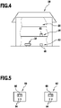
- FIGS 3 , 4 and 5 12 schematically show stations 60 and 62 for loading and/or emptying the floor cleaning device 10.
- the station 60 is arranged in the room 52, the station 62 in the room 54.
- the floor cleaning device 10 can contact electrical contact elements 64 of the respective station 60, 62 so that a battery of the floor cleaning device 10 can be charged.
- the dirt collection container 28 can be emptied via an unloading point not shown in the drawing.
- Stations 60, 62 include markers 66, 68, respectively, which are distinct from one another. Based on this difference, the floor cleaning device 10 can determine which station 60 or 62 is involved. Accordingly, the floor cleaning device 10 can use this determination to make an assignment to the room 52 or 54 and determine in which of these rooms 52, 54 it is located.
- the markings 66, 68 are, for example, reflective elements that reflect signals emitted by the sensor unit 42, which can be received by the sensor unit 42 again.
- the tag 66, 68 can also be an RFID tag or some other type of tag by which the stations 60, 62 can be distinguished.
- marking elements can also be used to mark a room 52, 54, 56, as already mentioned, for example marking posts, cones or cubes.
- identifying rooms 52, 54, 56 can be carried out, for example, using matrix codes (for example QR codes), barcodes or RFID tags, which are arranged in rooms 52, 54 or 56.
- matrix codes for example QR codes
- barcodes for example QR codes
- RFID tags which are arranged in rooms 52, 54 or 56.
Landscapes
- Engineering & Computer Science (AREA)
- Radar, Positioning & Navigation (AREA)
- Mechanical Engineering (AREA)
- Aviation & Aerospace Engineering (AREA)
- Remote Sensing (AREA)
- Physics & Mathematics (AREA)
- General Physics & Mathematics (AREA)
- Automation & Control Theory (AREA)
- Control Of Position, Course, Altitude, Or Attitude Of Moving Bodies (AREA)
- Electric Vacuum Cleaner (AREA)
- Instructional Devices (AREA)
Priority Applications (1)
| Application Number | Priority Date | Filing Date | Title |
|---|---|---|---|
| EP20200113.7A EP3822730B1 (de) | 2013-08-06 | 2013-08-06 | Verfahren zum betreiben eines bodenreinigungsgerätes und bodenreinigungsgerät |
Applications Claiming Priority (3)
| Application Number | Priority Date | Filing Date | Title |
|---|---|---|---|
| PCT/EP2013/066463 WO2015018437A1 (de) | 2013-08-06 | 2013-08-06 | Verfahren zum betreiben eines bodenreinigungsgerätes und bodenreinigungsgerät |
| EP13747828.5A EP3030943B1 (de) | 2013-08-06 | 2013-08-06 | Verfahren zum betreiben eines bodenreinigungsgerätes und bodenreinigungsgerät |
| EP20200113.7A EP3822730B1 (de) | 2013-08-06 | 2013-08-06 | Verfahren zum betreiben eines bodenreinigungsgerätes und bodenreinigungsgerät |
Related Parent Applications (1)
| Application Number | Title | Priority Date | Filing Date |
|---|---|---|---|
| EP13747828.5A Division EP3030943B1 (de) | 2013-08-06 | 2013-08-06 | Verfahren zum betreiben eines bodenreinigungsgerätes und bodenreinigungsgerät |
Publications (2)
| Publication Number | Publication Date |
|---|---|
| EP3822730A1 EP3822730A1 (de) | 2021-05-19 |
| EP3822730B1 true EP3822730B1 (de) | 2022-12-07 |
Family
ID=48953382
Family Applications (2)
| Application Number | Title | Priority Date | Filing Date |
|---|---|---|---|
| EP20200113.7A Active EP3822730B1 (de) | 2013-08-06 | 2013-08-06 | Verfahren zum betreiben eines bodenreinigungsgerätes und bodenreinigungsgerät |
| EP13747828.5A Active EP3030943B1 (de) | 2013-08-06 | 2013-08-06 | Verfahren zum betreiben eines bodenreinigungsgerätes und bodenreinigungsgerät |
Family Applications After (1)
| Application Number | Title | Priority Date | Filing Date |
|---|---|---|---|
| EP13747828.5A Active EP3030943B1 (de) | 2013-08-06 | 2013-08-06 | Verfahren zum betreiben eines bodenreinigungsgerätes und bodenreinigungsgerät |
Country Status (5)
| Country | Link |
|---|---|
| US (1) | US10478037B2 (enExample) |
| EP (2) | EP3822730B1 (enExample) |
| JP (1) | JP6406680B2 (enExample) |
| CN (1) | CN105593775B (enExample) |
| WO (1) | WO2015018437A1 (enExample) |
Families Citing this family (38)
| Publication number | Priority date | Publication date | Assignee | Title |
|---|---|---|---|---|
| US10518407B2 (en) * | 2015-01-06 | 2019-12-31 | Discovery Robotics | Apparatus and methods for providing a reconfigurable robotic platform |
| US11400595B2 (en) | 2015-01-06 | 2022-08-02 | Nexus Robotics Llc | Robotic platform with area cleaning mode |
| CN107636548B (zh) * | 2015-05-12 | 2021-08-13 | 三星电子株式会社 | 机器人及其控制方法 |
| KR102393921B1 (ko) | 2015-05-12 | 2022-05-04 | 삼성전자주식회사 | 로봇 및 그의 제어 방법 |
| DE102015109775B3 (de) | 2015-06-18 | 2016-09-22 | RobArt GmbH | Optischer Triangulationssensor zur Entfernungsmessung |
| DE102015114883A1 (de) | 2015-09-04 | 2017-03-09 | RobArt GmbH | Identifizierung und Lokalisierung einer Basisstation eines autonomen mobilen Roboters |
| DE102015119501A1 (de) | 2015-11-11 | 2017-05-11 | RobArt GmbH | Unterteilung von Karten für die Roboternavigation |
| DE102015119865B4 (de) | 2015-11-17 | 2023-12-21 | RobArt GmbH | Robotergestützte Bearbeitung einer Oberfläche mittels eines Roboters |
| DE102015121666B3 (de) | 2015-12-11 | 2017-05-24 | RobArt GmbH | Fernsteuerung eines mobilen, autonomen Roboters |
| DE102016102644A1 (de) | 2016-02-15 | 2017-08-17 | RobArt GmbH | Verfahren zur Steuerung eines autonomen mobilen Roboters |
| JP7058067B2 (ja) * | 2016-02-16 | 2022-04-21 | 東芝ライフスタイル株式会社 | 自律走行体 |
| DE102016108513A1 (de) * | 2016-05-09 | 2017-11-09 | Vorwerk & Co. Interholding Gmbh | System und ein Verfahren zur Reinigung eines Fußbodens mit einem Reinigungsroboter |
| JP6757593B2 (ja) * | 2016-05-11 | 2020-09-23 | シャープ株式会社 | 自走式電子機器 |
| DE102016114593A1 (de) * | 2016-08-05 | 2018-02-08 | RobArt GmbH | Verfahren zur Steuerung eines autonomen mobilen Roboters |
| US12140965B2 (en) | 2016-08-05 | 2024-11-12 | Rotrade Asset Management Gmbh | Method for controlling an autonomous mobile robot |
| KR20180082264A (ko) * | 2017-01-10 | 2018-07-18 | 엘지전자 주식회사 | 이동 로봇 및 그 제어방법 |
| US11709489B2 (en) | 2017-03-02 | 2023-07-25 | RobArt GmbH | Method for controlling an autonomous, mobile robot |
| DE102017109219A1 (de) | 2017-04-28 | 2018-10-31 | RobArt GmbH | Verfahren für die Roboternavigation |
| DE102017207341A1 (de) * | 2017-05-02 | 2018-11-08 | Henkel Ag & Co. Kgaa | Verfahren zur Steuerung von Reinigungsgeräten |
| US20180344116A1 (en) | 2017-06-02 | 2018-12-06 | Irobot Corporation | Scheduling and control system for autonomous robots |
| US10422648B2 (en) * | 2017-10-17 | 2019-09-24 | AI Incorporated | Methods for finding the perimeter of a place using observed coordinates |
| DE102017127180A1 (de) | 2017-11-17 | 2019-05-23 | RobArt GmbH | Bodenbearbeitung mittels eines autonomen mobilen Roboters |
| JP6945144B2 (ja) * | 2017-12-14 | 2021-10-06 | パナソニックIpマネジメント株式会社 | 掃除情報提供装置、および掃除機システム |
| CN108209745B (zh) * | 2017-12-18 | 2021-06-25 | 深圳市奇虎智能科技有限公司 | 清洁设备的控制方法、装置、计算机设备和存储介质 |
| JP6850970B2 (ja) * | 2018-02-21 | 2021-03-31 | パナソニックIpマネジメント株式会社 | 自律走行型掃除機 |
| JP7025990B2 (ja) * | 2018-05-14 | 2022-02-25 | 日立グローバルライフソリューションズ株式会社 | 移動体、および、移動体の地図共有方法 |
| CN108614562B (zh) * | 2018-06-05 | 2021-05-07 | 北京智行者科技有限公司 | 一种清扫路径优化方法 |
| JP7123656B2 (ja) * | 2018-06-22 | 2022-08-23 | 東芝ライフスタイル株式会社 | 自律型電気掃除機 |
| US11157016B2 (en) * | 2018-07-10 | 2021-10-26 | Neato Robotics, Inc. | Automatic recognition of multiple floorplans by cleaning robot |
| US10835096B2 (en) * | 2018-08-30 | 2020-11-17 | Irobot Corporation | Map based training and interface for mobile robots |
| CN110936371A (zh) * | 2018-09-25 | 2020-03-31 | 上海云绅智能科技有限公司 | 一种多楼层地图切换方法及机器人 |
| DE102018131732A1 (de) * | 2018-12-11 | 2020-06-18 | Vorwerk & Co. Interholding Gmbh | System aus mindestens einem Bodenbearbeitungsgerät und mindestens einer Signalsendeeinrichtung sowie Betriebsverfahren dafür |
| KR102715879B1 (ko) * | 2019-03-07 | 2024-10-14 | 삼성전자주식회사 | 전자 장치 및 그 제어 방법 |
| DE102019128927A1 (de) * | 2019-10-25 | 2021-04-29 | Vorwerk & Co. Interholding Gmbh | Verfahren zur Erstellung einer Umgebungskarte für ein sich selbsttätig fortbewegendes Bodenbearbeitungsgerät, sowie System aus zwei sich selbsttätig fortbewegenden Bodenbearbeitungsgeräten |
| CN110840335B (zh) * | 2019-11-07 | 2021-09-10 | 深圳市银星智能科技股份有限公司 | 机器人位置状态检测方法及其机器人 |
| CN113100674A (zh) * | 2020-04-28 | 2021-07-13 | 杨炳辉 | 一种地面清洗装置 |
| JP7558718B2 (ja) * | 2020-08-25 | 2024-10-01 | 日本信号株式会社 | 床掃除機 |
| EP4579193A3 (en) * | 2021-06-17 | 2025-07-30 | The Toro Company | Autonomous work vehicle using image-based localization |
Family Cites Families (22)
| Publication number | Priority date | Publication date | Assignee | Title |
|---|---|---|---|---|
| IL124413A (en) * | 1998-05-11 | 2001-05-20 | Friendly Robotics Ltd | System and method for area coverage with an autonomous robot |
| JP2002085305A (ja) * | 2000-09-12 | 2002-03-26 | Toshiba Tec Corp | ロボットクリーナ及びロボットクリーナシステム |
| RU2220643C2 (ru) | 2001-04-18 | 2004-01-10 | Самсунг Гванджу Электроникс Ко., Лтд. | Автоматическое чистящее устройство, автоматическая чистящая система и способ управления этой системой (варианты) |
| US6667592B2 (en) * | 2001-08-13 | 2003-12-23 | Intellibot, L.L.C. | Mapped robot system |
| KR100478653B1 (ko) * | 2002-06-25 | 2005-03-24 | 삼성광주전자 주식회사 | 로봇 청소기의 작업 영역 인식방법 |
| US20040236468A1 (en) * | 2003-03-14 | 2004-11-25 | Taylor Charles E. | Robot vacuum with remote control mode |
| US7170252B2 (en) * | 2003-07-23 | 2007-01-30 | Renesas Technology Corporation | Location aware automata |
| KR100538934B1 (ko) * | 2003-07-24 | 2005-12-27 | 삼성광주전자 주식회사 | 청소시스템 및 이의 제어방법 |
| JP2005211359A (ja) * | 2004-01-30 | 2005-08-11 | Funai Electric Co Ltd | 自律走行ロボットクリーナーシステム |
| JP2005216021A (ja) * | 2004-01-30 | 2005-08-11 | Funai Electric Co Ltd | 自律走行ロボットクリーナー |
| US8972052B2 (en) * | 2004-07-07 | 2015-03-03 | Irobot Corporation | Celestial navigation system for an autonomous vehicle |
| JP2006106816A (ja) * | 2004-09-30 | 2006-04-20 | Toshiba Tec Corp | 電気掃除機 |
| EP2829939B1 (en) * | 2005-12-02 | 2019-11-13 | iRobot Corporation | Autonomous coverage robot navigation system |
| KR101290378B1 (ko) | 2005-12-02 | 2013-07-26 | 아이로보트 코퍼레이션 | 자동 커버리지 로봇 운행 시스템 |
| KR100730311B1 (ko) * | 2005-12-29 | 2007-06-19 | 에이스로봇 주식회사 | 위치 인식 로봇 청소기 및 로봇 청소기에서 위치 인식 방법 |
| WO2009132317A1 (en) * | 2008-04-24 | 2009-10-29 | Evolution Robotics | Application of localization, positioning & navigation systems for robotic enabled mobile products |
| KR101331706B1 (ko) * | 2009-06-30 | 2013-11-20 | 엘지전자 주식회사 | 로봇청소기 |
| DE102009041362A1 (de) | 2009-09-11 | 2011-03-24 | Vorwerk & Co. Interholding Gmbh | Verfahren zum Betreiben eines Reinigungsroboters |
| DE102010037100A1 (de) * | 2010-08-23 | 2012-02-23 | Vorwerk & Co. Interholding Gmbh | Selbsttätig verfahrbares Gerät |
| KR20120044768A (ko) * | 2010-10-28 | 2012-05-08 | 엘지전자 주식회사 | 로봇 청소기 및 이의 제어 방법 |
| DE102012201870A1 (de) | 2012-02-08 | 2013-08-08 | RobArt GmbH | Verfahren zum automatischen Auslösen einer Selbstlokalisierung |
| DE102012109004A1 (de) | 2012-09-24 | 2014-03-27 | RobArt GmbH | Roboter und Verfahren zur autonomen Inspektion oder Bearbeitung von Bodenflächen |
-
2013
- 2013-08-06 EP EP20200113.7A patent/EP3822730B1/de active Active
- 2013-08-06 JP JP2016532241A patent/JP6406680B2/ja active Active
- 2013-08-06 WO PCT/EP2013/066463 patent/WO2015018437A1/de not_active Ceased
- 2013-08-06 EP EP13747828.5A patent/EP3030943B1/de active Active
- 2013-08-06 CN CN201380078808.5A patent/CN105593775B/zh active Active
-
2016
- 2016-02-03 US US15/014,778 patent/US10478037B2/en active Active
Also Published As
| Publication number | Publication date |
|---|---|
| CN105593775A (zh) | 2016-05-18 |
| EP3030943A1 (de) | 2016-06-15 |
| US20160150933A1 (en) | 2016-06-02 |
| EP3030943B1 (de) | 2020-10-07 |
| CN105593775B (zh) | 2020-05-05 |
| JP2016527977A (ja) | 2016-09-15 |
| JP6406680B2 (ja) | 2018-10-17 |
| EP3822730A1 (de) | 2021-05-19 |
| WO2015018437A1 (de) | 2015-02-12 |
| US10478037B2 (en) | 2019-11-19 |
Similar Documents
| Publication | Publication Date | Title |
|---|---|---|
| EP3030943B1 (de) | Verfahren zum betreiben eines bodenreinigungsgerätes und bodenreinigungsgerät | |
| EP2812766B2 (de) | Verfahren zum automatischen auslösen einer selbstlokalisierung | |
| EP3709853B1 (de) | Bodenbearbeitung mittels eines autonomen mobilen roboters | |
| EP2898382B1 (de) | Roboter und verfahren zur autonomen inspektion oder bearbeitung von bodenflächen | |
| DE102011006062B4 (de) | Verfahren zur autonomen Inspektion einer Umgebung oder Bearbeitung von Bodenflächen | |
| EP2294960B1 (de) | Verfahren zum Betreiben eines Reinigungsroboters | |
| WO2017140726A1 (de) | Verfahren zur steuerung eines autonomen mobilen roboters | |
| EP4235342A2 (de) | Exploration eines robotereinsatzgebietes durch einen autonomen mobilen roboter | |
| EP3825802B1 (de) | System mit mindestens zwei sich selbsttätig fortbewegenden bodenbearbeitungsgeräten sowie verfahren zum betrieb des systems | |
| EP3379990B1 (de) | Bodenreinigungssystem und verfahren zum reinigen einer bodenfläche | |
| EP3974934A1 (de) | Verfahren zur steuerung eines autonomen, mobilen roboters | |
| EP3415065A1 (de) | System mit mindestens zwei reinigungsgeräten | |
| DE102017104427A1 (de) | Verfahren zur Steuerung eines autonomen, mobilen Roboters | |
| DE102015100419A1 (de) | Verfahren und Anordnung zum Bearbeiten von Bodenflächen | |
| EP3683645A1 (de) | System mit einem ersten bodenbearbeitungsgerät und einem zweiten bodenbearbeitungsgerät sowie verfahren zum betrieb eines solchen systems | |
| WO2018115153A1 (de) | Verfahren zur navigation und selbstlokalisierung eines sich autonom fortbewegenden bearbeitungsgerätes | |
| DE102024112364A1 (de) | Selbstbeweglicher Roboter, Verfahren zur Hindernisüberwindung, System zur Hindernisüberwindung und computerlesbares Speichermedium | |
| EP3848770B1 (de) | Verfahren zum betrieb eines systems mit zwei sich selbsttätig fortbewegenden bodenbearbeitungsgeräten sowie system zur durchführung eines solchen verfahrens | |
| DE102021205620A1 (de) | Verfahren zum Bestimmen eines Bewegungspfades auf einem Untergrund | |
| WO2018019366A1 (de) | Reinigungssystem und verfahren zur reinigung von flächen von räumen | |
| WO2023020699A1 (de) | Bodenreinigungssystem, bodenreinigungsgerät und verfahren zum betreiben eines bodenreinigungssystems oder eines bodenreinigungsgerätes | |
| DE102020208893A1 (de) | Steuerung eines Reinigungsroboters | |
| DE102018131732A1 (de) | System aus mindestens einem Bodenbearbeitungsgerät und mindestens einer Signalsendeeinrichtung sowie Betriebsverfahren dafür | |
| EP4660735A1 (de) | Reinigungsgerät und verfahren zum betreiben eines reinigungsgeräts | |
| EP4434422A1 (de) | Verfahren zum betreiben eines selbstfahrenden reinigungsgeräts und selbstfahrendes reinigungsgerät |
Legal Events
| Date | Code | Title | Description |
|---|---|---|---|
| PUAI | Public reference made under article 153(3) epc to a published international application that has entered the european phase |
Free format text: ORIGINAL CODE: 0009012 |
|
| STAA | Information on the status of an ep patent application or granted ep patent |
Free format text: STATUS: THE APPLICATION HAS BEEN PUBLISHED |
|
| AC | Divisional application: reference to earlier application |
Ref document number: 3030943 Country of ref document: EP Kind code of ref document: P |
|
| AK | Designated contracting states |
Kind code of ref document: A1 Designated state(s): AL AT BE BG CH CY CZ DE DK EE ES FI FR GB GR HR HU IE IS IT LI LT LU LV MC MK MT NL NO PL PT RO RS SE SI SK SM TR |
|
| STAA | Information on the status of an ep patent application or granted ep patent |
Free format text: STATUS: REQUEST FOR EXAMINATION WAS MADE |
|
| 17P | Request for examination filed |
Effective date: 20211119 |
|
| RBV | Designated contracting states (corrected) |
Designated state(s): AL AT BE BG CH CY CZ DE DK EE ES FI FR GB GR HR HU IE IS IT LI LT LU LV MC MK MT NL NO PL PT RO RS SE SI SK SM TR |
|
| INTG | Intention to grant announced |
Effective date: 20220316 |
|
| RAP3 | Party data changed (applicant data changed or rights of an application transferred) |
Owner name: ROBART GMBH |
|
| GRAJ | Information related to disapproval of communication of intention to grant by the applicant or resumption of examination proceedings by the epo deleted |
Free format text: ORIGINAL CODE: EPIDOSDIGR1 |
|
| GRAP | Despatch of communication of intention to grant a patent |
Free format text: ORIGINAL CODE: EPIDOSNIGR1 |
|
| STAA | Information on the status of an ep patent application or granted ep patent |
Free format text: STATUS: GRANT OF PATENT IS INTENDED |
|
| INTC | Intention to grant announced (deleted) | ||
| INTG | Intention to grant announced |
Effective date: 20220804 |
|
| GRAS | Grant fee paid |
Free format text: ORIGINAL CODE: EPIDOSNIGR3 |
|
| GRAA | (expected) grant |
Free format text: ORIGINAL CODE: 0009210 |
|
| STAA | Information on the status of an ep patent application or granted ep patent |
Free format text: STATUS: THE PATENT HAS BEEN GRANTED |
|
| AC | Divisional application: reference to earlier application |
Ref document number: 3030943 Country of ref document: EP Kind code of ref document: P |
|
| AK | Designated contracting states |
Kind code of ref document: B1 Designated state(s): AL AT BE BG CH CY CZ DE DK EE ES FI FR GB GR HR HU IE IS IT LI LT LU LV MC MK MT NL NO PL PT RO RS SE SI SK SM TR |
|
| REG | Reference to a national code |
Ref country code: GB Ref legal event code: FG4D Free format text: NOT ENGLISH |
|
| REG | Reference to a national code |
Ref country code: CH Ref legal event code: EP Ref country code: AT Ref legal event code: REF Ref document number: 1536666 Country of ref document: AT Kind code of ref document: T Effective date: 20221215 |
|
| REG | Reference to a national code |
Ref country code: DE Ref legal event code: R096 Ref document number: 502013016309 Country of ref document: DE |
|
| REG | Reference to a national code |
Ref country code: IE Ref legal event code: FG4D Free format text: LANGUAGE OF EP DOCUMENT: GERMAN |
|
| REG | Reference to a national code |
Ref country code: LT Ref legal event code: MG9D |
|
| REG | Reference to a national code |
Ref country code: NL Ref legal event code: MP Effective date: 20221207 |
|
| PG25 | Lapsed in a contracting state [announced via postgrant information from national office to epo] |
Ref country code: SE Free format text: LAPSE BECAUSE OF FAILURE TO SUBMIT A TRANSLATION OF THE DESCRIPTION OR TO PAY THE FEE WITHIN THE PRESCRIBED TIME-LIMIT Effective date: 20221207 Ref country code: NO Free format text: LAPSE BECAUSE OF FAILURE TO SUBMIT A TRANSLATION OF THE DESCRIPTION OR TO PAY THE FEE WITHIN THE PRESCRIBED TIME-LIMIT Effective date: 20230307 Ref country code: LT Free format text: LAPSE BECAUSE OF FAILURE TO SUBMIT A TRANSLATION OF THE DESCRIPTION OR TO PAY THE FEE WITHIN THE PRESCRIBED TIME-LIMIT Effective date: 20221207 Ref country code: FI Free format text: LAPSE BECAUSE OF FAILURE TO SUBMIT A TRANSLATION OF THE DESCRIPTION OR TO PAY THE FEE WITHIN THE PRESCRIBED TIME-LIMIT Effective date: 20221207 Ref country code: ES Free format text: LAPSE BECAUSE OF FAILURE TO SUBMIT A TRANSLATION OF THE DESCRIPTION OR TO PAY THE FEE WITHIN THE PRESCRIBED TIME-LIMIT Effective date: 20221207 |
|
| PG25 | Lapsed in a contracting state [announced via postgrant information from national office to epo] |
Ref country code: RS Free format text: LAPSE BECAUSE OF FAILURE TO SUBMIT A TRANSLATION OF THE DESCRIPTION OR TO PAY THE FEE WITHIN THE PRESCRIBED TIME-LIMIT Effective date: 20221207 Ref country code: PL Free format text: LAPSE BECAUSE OF FAILURE TO SUBMIT A TRANSLATION OF THE DESCRIPTION OR TO PAY THE FEE WITHIN THE PRESCRIBED TIME-LIMIT Effective date: 20221207 Ref country code: LV Free format text: LAPSE BECAUSE OF FAILURE TO SUBMIT A TRANSLATION OF THE DESCRIPTION OR TO PAY THE FEE WITHIN THE PRESCRIBED TIME-LIMIT Effective date: 20221207 Ref country code: HR Free format text: LAPSE BECAUSE OF FAILURE TO SUBMIT A TRANSLATION OF THE DESCRIPTION OR TO PAY THE FEE WITHIN THE PRESCRIBED TIME-LIMIT Effective date: 20221207 Ref country code: GR Free format text: LAPSE BECAUSE OF FAILURE TO SUBMIT A TRANSLATION OF THE DESCRIPTION OR TO PAY THE FEE WITHIN THE PRESCRIBED TIME-LIMIT Effective date: 20230308 |
|
| PG25 | Lapsed in a contracting state [announced via postgrant information from national office to epo] |
Ref country code: NL Free format text: LAPSE BECAUSE OF FAILURE TO SUBMIT A TRANSLATION OF THE DESCRIPTION OR TO PAY THE FEE WITHIN THE PRESCRIBED TIME-LIMIT Effective date: 20221207 |
|
| P01 | Opt-out of the competence of the unified patent court (upc) registered |
Effective date: 20230531 |
|
| PG25 | Lapsed in a contracting state [announced via postgrant information from national office to epo] |
Ref country code: SM Free format text: LAPSE BECAUSE OF FAILURE TO SUBMIT A TRANSLATION OF THE DESCRIPTION OR TO PAY THE FEE WITHIN THE PRESCRIBED TIME-LIMIT Effective date: 20221207 Ref country code: RO Free format text: LAPSE BECAUSE OF FAILURE TO SUBMIT A TRANSLATION OF THE DESCRIPTION OR TO PAY THE FEE WITHIN THE PRESCRIBED TIME-LIMIT Effective date: 20221207 Ref country code: PT Free format text: LAPSE BECAUSE OF FAILURE TO SUBMIT A TRANSLATION OF THE DESCRIPTION OR TO PAY THE FEE WITHIN THE PRESCRIBED TIME-LIMIT Effective date: 20230410 Ref country code: EE Free format text: LAPSE BECAUSE OF FAILURE TO SUBMIT A TRANSLATION OF THE DESCRIPTION OR TO PAY THE FEE WITHIN THE PRESCRIBED TIME-LIMIT Effective date: 20221207 Ref country code: CZ Free format text: LAPSE BECAUSE OF FAILURE TO SUBMIT A TRANSLATION OF THE DESCRIPTION OR TO PAY THE FEE WITHIN THE PRESCRIBED TIME-LIMIT Effective date: 20221207 |
|
| PG25 | Lapsed in a contracting state [announced via postgrant information from national office to epo] |
Ref country code: SK Free format text: LAPSE BECAUSE OF FAILURE TO SUBMIT A TRANSLATION OF THE DESCRIPTION OR TO PAY THE FEE WITHIN THE PRESCRIBED TIME-LIMIT Effective date: 20221207 Ref country code: IS Free format text: LAPSE BECAUSE OF FAILURE TO SUBMIT A TRANSLATION OF THE DESCRIPTION OR TO PAY THE FEE WITHIN THE PRESCRIBED TIME-LIMIT Effective date: 20230407 Ref country code: AL Free format text: LAPSE BECAUSE OF FAILURE TO SUBMIT A TRANSLATION OF THE DESCRIPTION OR TO PAY THE FEE WITHIN THE PRESCRIBED TIME-LIMIT Effective date: 20221207 |
|
| REG | Reference to a national code |
Ref country code: DE Ref legal event code: R097 Ref document number: 502013016309 Country of ref document: DE |
|
| PLBE | No opposition filed within time limit |
Free format text: ORIGINAL CODE: 0009261 |
|
| STAA | Information on the status of an ep patent application or granted ep patent |
Free format text: STATUS: NO OPPOSITION FILED WITHIN TIME LIMIT |
|
| PG25 | Lapsed in a contracting state [announced via postgrant information from national office to epo] |
Ref country code: DK Free format text: LAPSE BECAUSE OF FAILURE TO SUBMIT A TRANSLATION OF THE DESCRIPTION OR TO PAY THE FEE WITHIN THE PRESCRIBED TIME-LIMIT Effective date: 20221207 |
|
| 26N | No opposition filed |
Effective date: 20230908 |
|
| REG | Reference to a national code |
Ref country code: DE Ref legal event code: R079 Ref document number: 502013016309 Country of ref document: DE Free format text: PREVIOUS MAIN CLASS: G05D0001020000 Ipc: G05D0001430000 |
|
| PG25 | Lapsed in a contracting state [announced via postgrant information from national office to epo] |
Ref country code: SI Free format text: LAPSE BECAUSE OF FAILURE TO SUBMIT A TRANSLATION OF THE DESCRIPTION OR TO PAY THE FEE WITHIN THE PRESCRIBED TIME-LIMIT Effective date: 20221207 |
|
| PG25 | Lapsed in a contracting state [announced via postgrant information from national office to epo] |
Ref country code: MC Free format text: LAPSE BECAUSE OF FAILURE TO SUBMIT A TRANSLATION OF THE DESCRIPTION OR TO PAY THE FEE WITHIN THE PRESCRIBED TIME-LIMIT Effective date: 20221207 |
|
| REG | Reference to a national code |
Ref country code: CH Ref legal event code: PL |
|
| PG25 | Lapsed in a contracting state [announced via postgrant information from national office to epo] |
Ref country code: MC Free format text: LAPSE BECAUSE OF FAILURE TO SUBMIT A TRANSLATION OF THE DESCRIPTION OR TO PAY THE FEE WITHIN THE PRESCRIBED TIME-LIMIT Effective date: 20221207 |
|
| PG25 | Lapsed in a contracting state [announced via postgrant information from national office to epo] |
Ref country code: LU Free format text: LAPSE BECAUSE OF NON-PAYMENT OF DUE FEES Effective date: 20230806 |
|
| PG25 | Lapsed in a contracting state [announced via postgrant information from national office to epo] |
Ref country code: LU Free format text: LAPSE BECAUSE OF NON-PAYMENT OF DUE FEES Effective date: 20230806 Ref country code: CH Free format text: LAPSE BECAUSE OF NON-PAYMENT OF DUE FEES Effective date: 20230831 |
|
| REG | Reference to a national code |
Ref country code: BE Ref legal event code: MM Effective date: 20230831 |
|
| REG | Reference to a national code |
Ref country code: IE Ref legal event code: MM4A |
|
| PG25 | Lapsed in a contracting state [announced via postgrant information from national office to epo] |
Ref country code: IT Free format text: LAPSE BECAUSE OF FAILURE TO SUBMIT A TRANSLATION OF THE DESCRIPTION OR TO PAY THE FEE WITHIN THE PRESCRIBED TIME-LIMIT Effective date: 20221207 |
|
| PG25 | Lapsed in a contracting state [announced via postgrant information from national office to epo] |
Ref country code: IE Free format text: LAPSE BECAUSE OF NON-PAYMENT OF DUE FEES Effective date: 20230806 |
|
| PG25 | Lapsed in a contracting state [announced via postgrant information from national office to epo] |
Ref country code: IE Free format text: LAPSE BECAUSE OF NON-PAYMENT OF DUE FEES Effective date: 20230806 |
|
| REG | Reference to a national code |
Ref country code: DE Ref legal event code: R081 Ref document number: 502013016309 Country of ref document: DE Owner name: PAPST LICENSING GMBH & CO. KG, DE Free format text: FORMER OWNER: ROBART GMBH, LINZ, AT Ref country code: DE Ref legal event code: R082 Ref document number: 502013016309 Country of ref document: DE Representative=s name: WESTPHAL, MUSSGNUG & PARTNER PATENTANWAELTE MI, DE Ref country code: DE Ref legal event code: R081 Ref document number: 502013016309 Country of ref document: DE Owner name: ROTRADE ASSET MANAGEMENT GMBH, AT Free format text: FORMER OWNER: ROBART GMBH, LINZ, AT Ref country code: DE Ref legal event code: R082 Ref document number: 502013016309 Country of ref document: DE Representative=s name: HKW INTELLECTUAL PROPERTY PARTG MBB, DE |
|
| PG25 | Lapsed in a contracting state [announced via postgrant information from national office to epo] |
Ref country code: BE Free format text: LAPSE BECAUSE OF NON-PAYMENT OF DUE FEES Effective date: 20230831 |
|
| REG | Reference to a national code |
Ref country code: AT Ref legal event code: MM01 Ref document number: 1536666 Country of ref document: AT Kind code of ref document: T Effective date: 20230806 |
|
| PG25 | Lapsed in a contracting state [announced via postgrant information from national office to epo] |
Ref country code: AT Free format text: LAPSE BECAUSE OF NON-PAYMENT OF DUE FEES Effective date: 20230806 |
|
| PG25 | Lapsed in a contracting state [announced via postgrant information from national office to epo] |
Ref country code: AT Free format text: LAPSE BECAUSE OF NON-PAYMENT OF DUE FEES Effective date: 20230806 |
|
| PG25 | Lapsed in a contracting state [announced via postgrant information from national office to epo] |
Ref country code: BG Free format text: LAPSE BECAUSE OF FAILURE TO SUBMIT A TRANSLATION OF THE DESCRIPTION OR TO PAY THE FEE WITHIN THE PRESCRIBED TIME-LIMIT Effective date: 20221207 |
|
| PG25 | Lapsed in a contracting state [announced via postgrant information from national office to epo] |
Ref country code: BG Free format text: LAPSE BECAUSE OF FAILURE TO SUBMIT A TRANSLATION OF THE DESCRIPTION OR TO PAY THE FEE WITHIN THE PRESCRIBED TIME-LIMIT Effective date: 20221207 |
|
| REG | Reference to a national code |
Ref country code: GB Ref legal event code: 732E Free format text: REGISTERED BETWEEN 20250213 AND 20250219 |
|
| REG | Reference to a national code |
Ref country code: DE Ref legal event code: R081 Ref document number: 502013016309 Country of ref document: DE Owner name: PAPST LICENSING GMBH & CO. KG, DE Free format text: FORMER OWNER: ROTRADE ASSET MANAGEMENT GMBH, LEONDING, AT |
|
| REG | Reference to a national code |
Ref country code: GB Ref legal event code: 732E Free format text: REGISTERED BETWEEN 20250306 AND 20250312 |
|
| PG25 | Lapsed in a contracting state [announced via postgrant information from national office to epo] |
Ref country code: CY Free format text: LAPSE BECAUSE OF FAILURE TO SUBMIT A TRANSLATION OF THE DESCRIPTION OR TO PAY THE FEE WITHIN THE PRESCRIBED TIME-LIMIT; INVALID AB INITIO Effective date: 20130806 |
|
| PG25 | Lapsed in a contracting state [announced via postgrant information from national office to epo] |
Ref country code: HU Free format text: LAPSE BECAUSE OF FAILURE TO SUBMIT A TRANSLATION OF THE DESCRIPTION OR TO PAY THE FEE WITHIN THE PRESCRIBED TIME-LIMIT; INVALID AB INITIO Effective date: 20130806 |
|
| REG | Reference to a national code |
Ref country code: DE Ref legal event code: R008 Ref document number: 502013016309 Country of ref document: DE Ref country code: DE Ref legal event code: R039 Ref document number: 502013016309 Country of ref document: DE |
|
| PGFP | Annual fee paid to national office [announced via postgrant information from national office to epo] |
Ref country code: DE Payment date: 20250922 Year of fee payment: 13 |
|
| PGFP | Annual fee paid to national office [announced via postgrant information from national office to epo] |
Ref country code: GB Payment date: 20250822 Year of fee payment: 13 |
|
| PGFP | Annual fee paid to national office [announced via postgrant information from national office to epo] |
Ref country code: FR Payment date: 20250821 Year of fee payment: 13 |
|
| PG25 | Lapsed in a contracting state [announced via postgrant information from national office to epo] |
Ref country code: TR Free format text: LAPSE BECAUSE OF FAILURE TO SUBMIT A TRANSLATION OF THE DESCRIPTION OR TO PAY THE FEE WITHIN THE PRESCRIBED TIME-LIMIT Effective date: 20221207 |
|
| REG | Reference to a national code |
Ref country code: DE Ref legal event code: R082 Ref document number: 502013016309 Country of ref document: DE Representative=s name: HKW INTELLECTUAL PROPERTY PARTG MBB, DE |