EP3822609A1 - Vorrichtung und verfahren zur konditionierung eines betriebsfluids - Google Patents
Vorrichtung und verfahren zur konditionierung eines betriebsfluids Download PDFInfo
- Publication number
- EP3822609A1 EP3822609A1 EP20206751.8A EP20206751A EP3822609A1 EP 3822609 A1 EP3822609 A1 EP 3822609A1 EP 20206751 A EP20206751 A EP 20206751A EP 3822609 A1 EP3822609 A1 EP 3822609A1
- Authority
- EP
- European Patent Office
- Prior art keywords
- heat transfer
- operating
- fluid flow
- temperature
- heat
- Prior art date
- Legal status (The legal status is an assumption and is not a legal conclusion. Google has not performed a legal analysis and makes no representation as to the accuracy of the status listed.)
- Granted
Links
Images


Classifications
-
- G—PHYSICS
- G01—MEASURING; TESTING
- G01M—TESTING STATIC OR DYNAMIC BALANCE OF MACHINES OR STRUCTURES; TESTING OF STRUCTURES OR APPARATUS, NOT OTHERWISE PROVIDED FOR
- G01M15/00—Testing of engines
- G01M15/04—Testing internal-combustion engines
- G01M15/042—Testing internal-combustion engines by monitoring a single specific parameter not covered by groups G01M15/06 - G01M15/12
- G01M15/048—Testing internal-combustion engines by monitoring a single specific parameter not covered by groups G01M15/06 - G01M15/12 by monitoring temperature
-
- G—PHYSICS
- G01—MEASURING; TESTING
- G01M—TESTING STATIC OR DYNAMIC BALANCE OF MACHINES OR STRUCTURES; TESTING OF STRUCTURES OR APPARATUS, NOT OTHERWISE PROVIDED FOR
- G01M15/00—Testing of engines
- G01M15/04—Testing internal-combustion engines
- G01M15/09—Testing internal-combustion engines by monitoring pressure in fluid ducts, e.g. in lubrication or cooling parts
-
- G—PHYSICS
- G01—MEASURING; TESTING
- G01M—TESTING STATIC OR DYNAMIC BALANCE OF MACHINES OR STRUCTURES; TESTING OF STRUCTURES OR APPARATUS, NOT OTHERWISE PROVIDED FOR
- G01M99/00—Subject matter not provided for in other groups of this subclass
- G01M99/002—Thermal testing
Definitions
- the present disclosure relates to a device for conditioning an operating fluid on a test bench, the device having an operating line arrangement for the operating fluid which opens into a feed to a test object, the operating fluid fed into the feed being controllable to an inlet temperature within an operating temperature range, wherein the device has a conditioning line arrangement via which at least one heat transfer fluid is conducted to at least one heat exchanger and wherein the at least one heat exchanger is arranged for heat exchange between the conditioning line arrangement and the operating line arrangement.
- the present disclosure relates to a method for conditioning an operating fluid on a test stand, the operating fluid being supplied to a test object with an inlet temperature regulated within an operating temperature range, and the operating fluid being passed through at least one heat exchanger before being supplied, in which heat is exchanged with a heat transfer fluid he follows.
- Devices and methods of this type are used on test stands in order to condition fluid media of different types, for example cooling air, cooling liquid, fuel or similar fluids, to certain specified temperatures.
- other parameters such as the pressure state, the flow rate, the humidity, etc. can also be set.
- the set parameters are kept constant at a set value over defined periods of time. For a change to a different default value, transition times are usually defined within which the new default value should be reached.
- a regulation of the trajectory i.e., for example, the temperature profile
- the time delays in the regulation and the long response times which are due to the considerable thermal masses, prevent this.
- US 2012125564 A1 discloses a device for regulating the temperature of a coolant for an engine test bench, the coolant being passed over a heat exchanger and cooled by means of an external cooling circuit.
- the present disclosure relates to a device of the type mentioned at the beginning, in which the conditioning line arrangement has at least a first Has heat carrier inlet for supplying a first heat carrier fluid flow with a first heat carrier temperature and at least one second heat carrier inlet for supplying a second heat carrier fluid flow with a second heat carrier temperature, the first heat carrier temperature being adjustable to a value below the operating temperature range, the second heat carrier temperature being adjustable to a value above the operating temperature range and wherein the device has an adjusting valve arrangement with which the inlet temperature of the operating fluid can be dynamically regulated within the operating temperature range by controlled mixing of at least two fluids of different temperatures.
- This allows a dynamic tracking of variable default values of the inlet temperature of the operating fluid, whereby complex test specifications can be reproduced exactly and repeatably.
- the adjusting valve arrangement can have compressed air actuated valves and / or other highly dynamically actuable valves, whereby highly dynamic adjusting movements of the valves can be achieved. Regardless of the type of valve used, it must be ensured that a sufficiently high level of precision and speed of valve control can be achieved with the respective actuation mechanism.
- highly dynamic, electrically driven valves for example with servomotors are particularly suitable.
- the conditioning line arrangement can have a connection between the line areas for the first heat transfer fluid flow and the second heat transfer fluid flow. This presupposes that the same heat transfer fluid is used as the heat transfer fluid for the first heat transfer fluid flow and the second heat transfer fluid flow.
- the effort for the conditioning line arrangement and the necessary devices for the provision of the heat transfer fluid can be considerably reduced (for example devices can be realized that can do with a single heat exchanger).
- water, oils, essentially saturated salt solutions or comparable fluids for example, can be used as the heat transfer fluid, to which additives can optionally be added.
- a water-glycol mixture can be used as the heat transfer fluid.
- the adjusting valve arrangement can advantageously be arranged in the conditioning line arrangement.
- the first heat transfer fluid flow and the second heat transfer fluid flow (and possibly further heat transfer fluid flows) are mixed in a controlled manner and passed into the heat exchanger.
- the heat flow between the (mixed) heat transfer fluid and the operating fluid in the heat exchanger can be adjusted to a desired temperature or a desired temperature profile
- the inlet temperature of the operating fluid can be regulated. This assumes that the different heat transfer fluids are miscible, the use of identical heat transfer fluids being preferred.
- the conditioning line arrangement can have separate line regions for the first heat transfer fluid flow and the second heat transfer fluid flow.
- different heat transfer fluids can be used, each of which is optimized with regard to its heat transfer temperature, and the heat transfer can be improved. If necessary, larger operating temperature ranges can also be achieved in this way.
- the first heat transfer fluid flow can be fed to a first heat exchanger and the second heat transfer fluid flow can be fed to a second heat exchanger, the adjusting valve arrangement being arranged in the operating line arrangement.
- the flow of the operating fluid is divided between the two heat exchangers (heating / cooling) in a controlled manner. After the heat exchangers, the two flows are combined, resulting in the inlet temperature. This allows short conduction paths for the service line arrangement so that a low thermal inertia and a high control speed can be achieved.
- the adjusting valve arrangement can be arranged to mix a first operating fluid flow conditioned by the first heat exchanger with a second operating fluid flow conditioned by the second heat exchanger.
- the adjusting valve arrangement is arranged after the heat exchangers. This allows effort to be minimized since, for example, a single three-way valve is sufficient for setting the mixing ratio. Furthermore, the temperature setting (via the mixing ratio) can be made directly from the feed to the test object, whereby control delays can be minimized.
- the setting valve arrangement can optionally be arranged to split an operating fluid flow, preferably returned from the test object, into a first operating fluid flow to the first heat exchanger and a second operating fluid flow to the second heat exchanger.
- the division of the operating fluid flow between the two heat exchangers already takes place upstream of the heat exchangers.
- a turbolator can advantageously be arranged on or after the first operating fluid flow and the second operating fluid flow are brought together in order to improve the homogeneity of the temperature distribution in the operating fluid.
- the turbolator also improves the measurement dynamics and precision of a downstream temperature measurement.
- the device can be used for a positive and / or negative maximum temperature gradient of the inlet temperature of over 4 K / s, be designed preferably over 6 K / s and in particular over 8 K / s. This allows a highly dynamic change and control of the inlet temperature.
- the present disclosure relates to a method of the type mentioned at the outset, wherein at least one first heat transfer fluid flow with a first heat transfer temperature and at least one second heat transfer fluid flow with a second heat transfer temperature are used for conditioning, the first heat transfer temperature being set to a value below the operating temperature range , wherein the second heat transfer medium temperature is set to a value above the operating temperature range and wherein the inlet temperature of the operating fluid is dynamically regulated by controlled mixing of at least two fluids of different temperatures within the operating temperature range.
- the first heat transfer fluid flow and the second heat transfer fluid flow can be mixed in a controlled ratio to set the inlet temperature and the mixed heat transfer fluid flow can be fed to a heat exchanger for heat exchange with an operating fluid flow.
- the clear separation of heat transfer fluid and operating fluid allows the test stand to be quickly and easily adapted to different test objects. In particular, realistic volumes and pressure losses can also be mapped.
- the first heat transfer fluid flow can be fed to a first heat exchanger for heat exchange with a first operating fluid flow and the second heat transfer fluid flow can be fed to a second heat exchanger for heat exchange with a second operating fluid flow, the first operating fluid flow and the second operating fluid flow for setting the inlet temperature be mixed with each other in a regular ratio.
- a predictive regulation can advantageously be used to regulate the inlet temperature.
- Forward-looking regulations are, for example, from the publication AT 15462 U1 known per se. In conjunction with the teachings disclosed herein, the effects of such control methods can be greatly enhanced.
- the operating fluid can be regulated within an operating temperature range which has a minimum temperature in the range of about -40 ° C. to about 0 ° C. and a maximum temperature in the range of about 80 ° C. to 140 ° C., the operating temperature range preferably being between about -25 ° C. and about +125 ° C. Numerous test procedures can be carried out in this parameter area. Depending on the application, the devices and methods described herein can, however, also be set for different operating temperature ranges or designed for such.
- the first heat carrier temperature can be between -50 ° C and -10 ° C and in particular about -30 ° C, and / or the second heat carrier temperature can be between 100 ° C and 180 ° C and in particular about 150 ° C .
- Fig. 1 shows a schematic representation of a test stand 1, on which a test object 5 is subjected to a test. From the test stand 1, only selected elements are shown that are relevant in connection with the present disclosure, the elements shown relate in particular to the device for conditioning an operating fluid that the test object 5 at a certain temperature (and possibly under a certain pressure) via a Feed 4 is fed.
- the test bench 1 can be, for example, a vehicle test bench or an engine test bench. Accordingly, the test object can in particular be a vehicle or a heat engine, in particular an internal combustion engine, an electrical machine or a hybrid drive system.
- the operating fluid to be conditioned can in particular be a fluid supplied to the engine or the vehicle, for example conditioned outside air, engine cooling air, engine cooling liquid or a liquid or gaseous fuel.
- test object can also be a test object arranged in a test cell, the ambient air in the test cell being conditioned with the device.
- operating fluids refer to all flowable, in particular liquid or gaseous substances and mixtures of substances which influence the test object in operation and / or which the test object requires for operation.
- the unit of lines that contain the operating fluid, as well as the corresponding tanks, valves, measuring units, etc., is referred to as the operating line arrangement 2 in connection with the present disclosure.
- the operating fluid usually comes from a tank or from a return flow of the test object 5 into the operating line arrangement 2, is brought to the desired (and possibly variable) temperature and possibly to a certain pressure in this operating line arrangement 2, and then via a feed 4 to the test object 5 provided.
- the temperature that the operating fluid has at the feed 4 is referred to in connection with the present disclosure as the inlet temperature T a and this is the relevant control variable in the sense of the regulation.
- the operating line arrangement 2 comprises a simple circuit which leads from an operating medium outlet 11 of the test object via a heat exchanger 7 to the feed 4.
- a conditioning line arrangement 3 is provided, in which a heat transfer fluid (or possibly a plurality of heat transfer fluids) flow.
- the system boundary between the operating line arrangement 2 and the conditioning line arrangement 3 is indicated schematically as a dashed line.
- the heat flow 12 in FIG Fig. 1 illustrated case can run in one direction or the other. (Ie from the operating fluid to the heat transfer fluid - cooling - or from the heat transfer fluid to the operating fluid - heating).
- the conditioning line arrangement 3 has a first heat carrier inlet 8 and a second heat carrier inlet 9.
- a first heat transfer fluid flow with a first (colder) heat transfer temperature T l is fed in via the first heat transfer inlet 8, the first heat transfer temperature being below an operating temperature range within which the inlet temperature T a should be controllable.
- a second heat carrier fluid flow with a second (warmer) heat carrier temperature T h is fed in via the second heat carrier inlet 9, the second Heat transfer medium temperature is above the operating temperature range.
- the operating temperature range can either be fixed for a system or it can be set in certain ranges. If necessary, the operating temperature range can also be changed during a test run as a function of test parameters.
- the first heat transfer fluid flow can be branched off, for example, from a coolant circuit 13 in which the heat transfer fluid is kept at the defined first (low) heat transfer temperature in a circuit.
- the coolant circuit 13 comprises, in a manner known per se, a heat sink 131, a circuit pump 132 and an optionally adjustable pressure valve 133 with which the heat transfer fluid is kept at a feed pressure (at which the heat transfer fluid is diverted into the first heat transfer inlet 8).
- the second heat transfer fluid flow can be branched off, for example, from a heating medium circuit 14 in which the heat transfer fluid is kept at the defined second (high) heat transfer temperature in a circuit.
- the heating medium circuit 14 comprises, in a manner known per se, a heat source 141, a circuit pump 142 and an optionally adjustable pressure valve 143 with which the heat transfer fluid is kept at a feed pressure (at which the heat transfer fluid is diverted into the second heat transfer inlet 9).
- the first and the second heat transfer fluid flow in the conditioning line arrangement 3 are fed to an adjusting valve arrangement 6 and mixed with one another in a controlled manner.
- the adjusting valve assembly 6 can be in the in Fig. 1
- the embodiment shown may be, for example, a regulated 3-2-way valve, via which a desired volume ratio of the first and second heat transfer fluid flows can be set.
- other setting valve arrangements 6, for example two 2-2-way valves arranged in parallel before the two heat transfer fluid flows are brought together, can also be used.
- the adjusting valve arrangement 6 is connected to a control unit (not shown) which carries out the control as a function of a guide temperature (in particular the inlet temperature T a measured at the feed 4) and possibly taking into account predictive algorithms.
- the mixed heat transfer fluid flow is passed over the heat exchanger 7 and heats or cools the operating fluid there. After the heat exchanger 7, the heat transfer fluid flow is divided again and passed via pressure valves 301, 302 and return line connections 17 ′, 17 ′′ to the low-pressure side of the coolant circuit 13 or the heating medium circuit 14.
- Fig. 2 shows a further exemplary embodiment of a device for conditioning an operating fluid in a test stand 1.
- the conditioning line arrangement 3 of in Fig. 2 The device shown again has a first heat carrier inlet 8, via which heat carrier fluid is obtained from the high pressure side of a coolant circuit 13, and a second heat carrier inlet 9 via which heat carrier fluid is obtained from the high pressure side of a heating medium circuit 14.
- the conditioning line arrangement 3 guides the first heat transfer fluid flow from the first heat transfer inlet 8 via a first heat exchanger 7 ′ and a pressure valve 303 to a return line outlet 17 ′, from where it reaches the low-pressure side of the coolant circuit 13.
- the conditioning line arrangement 3 conducts the second heat transfer fluid flow from the second heat transfer inlet 9 via a second heat exchanger 7 ′ and a pressure valve 304 to a return outlet 17 ′′, from where it reaches the low-pressure side of the heating medium circuit 14.
- conditioning line arrangement 3 in this case has two fluidically separate circuits for the heat transfer fluid. If necessary, different heat transfer fluids can therefore also be used for the first heat transfer fluid flow and the second heat transfer fluid flow.
- the operating fluid flow originating from an operating medium outlet 11 of the test object 5 is divided at a branching point 15 into a first operating fluid flow and a second operating fluid flow.
- the first operating fluid flow passes through the first heat exchanger 7 '(cooling) and the second operating fluid flow passes through the second heat exchanger 7 "(heating).
- the two operating fluid flows are brought together again at a junction 16 and passed as one operating fluid flow to the feed 4 of the test object 5 .
- An adjusting valve arrangement 6 is provided at the junction 16, with which the volume ratios between the first (cold) operating fluid flow and the second (warm) operating fluid flow are regulated.
- the corresponding control unit is again not shown for the sake of clarity.
- the regulation takes place in turn as a function of a guide temperature, in particular the inlet temperature T a measured at the infeed 4, and possibly taking into account predictive algorithms.
- the adjusting valve arrangement 6 can also be provided at the branch point 15, the mode of operation being essentially unchanged.
- the first heat transfer fluid flow and / or the second heat transfer fluid flow can be controlled via control valves 305, 306 (shown in FIG Fig. 2 are indicated in dashed lines), if this is advantageous and desired as an additional control measure. This can save energy.
- the heat exchangers are only regulated to a defined temperature difference to the target temperature.
- a (possibly predictive) controller can increase or decrease the differential temperature depending on the dynamics.
- a fluid flow can be divided into two or more parallel lines with the help of several control valves (e.g. 2-2-way valves), which are arranged after a branch point in the individual parallel lines.
- control valves e.g. 2-2-way valves
- the mixing of fluid flows from several parallel lines can also take place at a junction by means of several control valves which are arranged in front of the junction in the individual parallel lines.
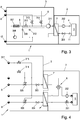
- Fig. 3 shows a schematic representation of a further embodiment of a device for conditioning an operating fluid in a test stand 1.
- the operating fluid flow is in a simple circuit coming from an operating medium outlet 11 of the test object 5 via a pressure valve 201, the heat exchanger 7 and a flow meter 202 to the feed 4 of the Test object 5 passed.
- a heating device 307 On the side of the conditioning line arrangement 3, a heating device 307, a pre-circuit pump 308 and a check valve 309 are arranged in a pre-circuit.
- the heat transfer fluid In the pre-circuit, the heat transfer fluid is heated to a second heat transfer temperature, diverted from the pre-circuit at a second heat-transfer inlet 9 and fed to a main circuit as a second heat-transfer fluid via a control valve 310.
- the heating device 307 can be, for example, an electrical heating unit, the power of which is sufficiently high to heat the heat carrier fluid in the pre-circuit quickly and strongly enough.
- the heating output can be adapted to the current demand. Instead of an electrical heating element, it is also possible, for example, to use a heat exchanger.
- the main circuit comprises a main circuit pump 311, the heat exchanger 7 and a check valve 312.
- a return line branches off between the outlet of the heat exchanger 7 and the check valve 312, which leads the return line outlet 17 and to an external circuit for the heat transfer fluid, in particular a coolant circuit 13.
- the coolant circuit 13 is in Fig. 3 not shown for the sake of clarity; Figs. 1 and 2 be formed coolant circuits shown.
- a first (cold) heat transfer fluid flow again reaches the conditioning line arrangement 3 via a first heat transfer inlet 8 and is fed into the main circuit via a further control valve 313. Furthermore, the device comprises a third heat transfer inlet 8 ′, via which a third heat transfer fluid flow is fed to the conditioning line arrangement 3. The third heat transfer fluid flow is fed into the main circuit via a third control valve 314. The third heat transfer fluid flow has a third heat transfer temperature which is between the first and the second heat transfer temperature.
- the third heat transfer medium temperature is preferably designed in such a way that in "normal operation" (for example when the test object 5 is operated in a stable state and only minor control interventions are required), the third control valve 314 and the control valve 310 are controlled by the upstream circuit (with the control valve 313 closed ) is sufficient to keep the operating fluid circulating in the operating line arrangement 2 in a desired operating temperature range.
- the other control valve 313 is only activated when rapid temperature changes or control interventions are required.
- a temperature setting can also be carried out with the control valve 310 closed (from the pre-circuit) by regulating the two control valves 313 and 314 of the first and third heat carrier inlets 8, 8 ′′ if the current operating temperature range is between the heat carrier temperatures of these two heat carrier fluids.
- the unit of the three control valves 310, 313 and 314 thus forms an adjusting valve arrangement 6, via which the temperature of the heat transfer fluid that is fed to the heat exchanger 7 can be changed in a controlled manner over a wide operating range. Since the heat transfer fluid flows use common circuits and a common return line, identical heat transfer fluids must be used.
- Fig. 4 shows a further embodiment of a conditioning unit for a test stand 1 with two heat exchangers 7 ′ and 7 ′′.
- the operating line arrangement 2 essentially corresponds to that in FIG Fig. 2 arrangement shown, wherein a controllable pressure valve 201 and a flow meter 202 are also provided.
- the pressure valve 201 can be used to adjust the real pressure losses of the test object.
- a first and a second heat transfer fluid inlet 8, 9 are again provided, the first and the second heat transfer fluid flow in turn being routed via their own separate return lines, so that separate circuits can be used for the two heat transfer fluid flows and, if necessary, different heat transfer fluids.
- the two pressure valves 303, 304 are provided in order to adjust the pressure drop of the system and thus the flow rates of the heat transfer fluid flows through the heat exchangers 7 ′, 7 ′′. This may be necessary when several conditioning devices are connected to a central coolant circuit 13 or heating medium circuit 14.
- a control valve 305, 306 is provided for each of the first and second heat transfer fluid streams, via which the flow rates of the heat transfer fluid streams are controlled.
- the two control valves are actuated by compressed air to allow highly dynamic valve movement.
- a compressed air valve 315, 316 which is connected to a compressed air inlet 317, is provided for actuating compressed air. In this way, the thermal energy can be regulated with high energy efficiency.
- the temperature can be regulated both via the two pressure-regulated control valves 305, 306 on the side of the conditioning line arrangement 3 and via the setting valve arrangement 6 on the side of the operating line arrangement 2.
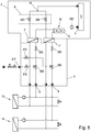
- Fig. 5 shows a further embodiment of the conditioning device in a test stand 1.
- the conditioning line arrangement 3 corresponds essentially to that in FIG Fig. 4 shown and described above, wherein in Fig. 5 the coolant circuit 13 and the heating medium circuit 14, as well as a compressed air supply line to the compressed air inlet 317 are shown.
- the coolant circuit 13 and the heating medium circuit 14, as well as the areas of the conditioning line arrangement 3 connected therewith, are each formed separately from one another, so that it is possible to use different heat transfer fluids.
- an adjusting valve arrangement 6 is again provided, which in this case is formed by two control valves 203, 204 arranged in parallel, each of which regulates the flow of the operating fluid via the corresponding heat exchanger 7 ', 7 "after the branching point 15 In heat exchangers, the two operating fluid flows are brought together at a junction 16, with a turbolator 10 being provided at the junction 16, which mixes the warm and cold operating fluid in order to ensure a uniform temperature at the feed 4.
- This arrangement allows rapid and precise control, Flow measurement and regulation can take place via the flow measuring device 202.
- the flow can also be determined on the basis of differential pressures, which can be determined using appropriate pressure sensors (not shown).
- the in Fig. 5 In the embodiment shown, a simplification of the operating line arrangement is possible by using the control valves 203 and 204 for the additional control of the pressure loss over the system and therefore does not have to provide a separate valve for this. In contrast to a 3-2 way control valve, the in Fig. 5 A linearization of the valve characteristic can be achieved with the two 2-2-way valves shown. This can increase the control accuracy.
- Fig. 6 shows a further embodiment of a device for conditioning an operating fluid, which in turn is based on a single heat exchanger 7.
- the operating line arrangement 2 is relatively simple in this case, with an operating fluid flow from an operating medium outlet 11 of the test object 5 via a flow meter 202 and a controllable pressure valve 201 via the heat exchanger 7 to a feed 4 of the test object 5.
- this relatively simple operating line arrangement 2 low pressure losses and realistic volumes can be achieved for the test object 5.
- the temperature control takes place on the side of the conditioning line arrangement 3.
- a first and a second heat transfer medium inlet 8, 9 are again provided.
- the two pressure valves 303, 304 are provided in order to adjust the pressure drop in the system and thus the flow rates of the heat transfer fluid flows through the heat exchanger 7.
- a control valve 305, 306 is provided for each of the first and second heat transfer fluid flows, via which the flow rates of the heat transfer fluid flows and their relationship to one another are controlled.
- the two control valves are actuated by compressed air to allow highly dynamic valve movement.
- a compressed air valve 315, 316 which is connected to a compressed air inlet 317, is provided for actuating compressed air.
- the check valves 318, 319 are used to set a defined zero point, independent of the system return pressure at the return outlets 17 ', 17 ".
- a differential pressure measurement (not shown) via the pressure valve 303 and the check valve 318 (or the pressure valve 304 and the check valve 319) are used, which are included in the control.
- a flow sensor can also be installed or a control-related pilot control can be used.
- the two heat transfer fluid flows after the check valves 318, 319 are brought together and allowed to circulate in a main circuit.
- the combined heat transfer fluid flow runs in the main circuit via a flow 321 to the heat exchanger 7 and via a return 322 to a main circuit pump 311.
- the main circuit pump 311 ensures that a flow of heat transfer fluid through the heat exchanger 7 is maintained even when the two control valves 305, 306 are closed.
- a further check valve 320 is arranged downstream of the main circuit pump 311. The first and the second heat transfer fluid flow open between the check valve 320 and the heat exchanger 7 in the flow 321.
- a return line branches off, which is divided into two return outlets 17 ', 17 ", which the heat transfer fluid again to the coolant circuit 13 and the Heating medium circuit 14 (in Fig. 6 not shown).
- Check valves 323, 324 are also provided in the return lines.
- sensors can be provided on the conditioning line arrangement 3 and / or the operating line arrangement 2 in all of the embodiments described above, in particular differential pressure sensors, flow sensors, pressure sensors and temperature sensors. For the sake of clarity, such sensors have largely not been shown in the figures. However, with knowledge of the teachings disclosed herein, the person skilled in the art is in a position to implement the necessary sensors in order to optimize the set control tasks.
Landscapes
- Physics & Mathematics (AREA)
- General Physics & Mathematics (AREA)
- Chemical & Material Sciences (AREA)
- Engineering & Computer Science (AREA)
- Combustion & Propulsion (AREA)
- Other Air-Conditioning Systems (AREA)
Abstract
Description
- Die gegenständliche Offenbarung betrifft eine Vorrichtung zur Konditionierung eines Betriebsfluids an einem Prüfstand, wobei die Vorrichtung eine Betriebsleitungsanordnung für das Betriebsfluid aufweist, welche in einer Einspeisung zu einem Testobjekt einmündet, wobei das in die Einspeisung eingespeiste Betriebsfluid auf eine Einleittemperatur innerhalb eines Betriebstemperaturbereichs regelbar ist, wobei die Vorrichtung eine Konditionierleitungsanordnung aufweist, über welche zumindest ein Wärmeträgerfluid zu zumindest einem Wärmetauscher geleitet wird und wobei der zumindest eine Wärmetauscher für einen Wärmeaustausch zwischen der Konditionierleitungsanordnung und der Betriebsleitungsanordnung angeordnet ist.
- Weiters betrifft die gegenständliche Offenbarung ein Verfahren zur Konditionierung eines Betriebsfluids an einem Prüfstand, wobei das Betriebsfluid mit einer innerhalb eines Betriebstemperaturbereichs geregelten Einleittemperatur einem Testobjekt zugeführt wird und wobei das Betriebsfluid vor dem Zuführen über zumindest einen Wärmetauscher geleitet wird, in dem ein Wärmeaustauch mit einem Wärmeträgerfluid erfolgt.
- Vorrichtungen und Verfahren dieser Art werden an Prüfständen verwendet, um Fluidmedien unterschiedlicher Art, beispielsweise Kühlluft, Kühlflüssigkeit, Treibstoff oder ähnliche Fluida, auf bestimmte Vorgabetemperaturen zu konditionieren. Gegebenenfalls kann auch eine Einstellung anderer Parameter, wie etwa des Druckzustands, der Fließrate, der Feuchtigkeit, etc. erfolgen. Die eingestellten Parameter werden dabei über definierte Zeitspannen auf einen eingestellten Wert konstant gehalten. Für einen Wechsel zu einem anderen Vorgabewert werden üblicherweise Übergangszeiten definiert, innerhalb derer der neue Vorgabewert erreicht sein soll. Eine Regelung der Trajektorie (d.h. etwa des Temperaturverlaufs) im Übergangsbereich zwischen zwei Vorgabewerten ist mit derzeit verwendeten Vorrichtungen und Verfahren aufgrund der komplexen Zusammenhänge nicht möglich. Insbesondere die Zeitverzögerungen der Regelung und die hohen Reaktionszeiten, die den erheblichen thermischen Massen geschuldet sind, verhindern dies.
-
US 2012125564 A1 offenbart eine Vorrichtung zur Temperaturregelung eines Kühlmittels für einen Motorprüfstand, wobei das Kühlmittel über einen Wärmetauscher geführt und mittels eines externen Kühlkreislaufs gekühlt wird. - Es besteht ein Bedarf an innovativen Ansätzen und Lösungen, mit denen sich die Regelgeschwindigkeit, das Ansprechverhalten und die Regelgenauigkeit von Konditionieranlagen verbessern lassen.
- In einem ersten Aspekt betrifft die gegenständliche Offenbarung eine Vorrichtung der eingangs genannten Art, bei der die Konditionierleitungsanordnung zumindest einen ersten Wärmeträgereinlass zur Zuleitung eines ersten Wärmeträgerfluidstroms mit einer ersten Wärmeträgertemperatur und zumindest einen zweiten Wärmeträgereinlass zur Zuleitung eines zweiten Wärmeträgerfluidstroms mit einer zweiten Wärmeträgertemperatur aufweist, wobei die erste Wärmeträgertemperatur auf einen Wert unterhalb des Betriebstemperaturbereichs einstellbar ist, wobei die zweite Wärmeträgertemperatur auf einen Wert oberhalb des Betriebstemperaturbereichs einstellbar ist und wobei die Vorrichtung eine Einstellventilanordnung aufweist, mit welcher durch geregeltes Mischen von zumindest zwei Fluida unterschiedlicher Temperatur die Einleittemperatur des Betriebsfluids innerhalb des Betriebstemperaturbereichs dynamisch regelbar ist. Dies erlaubt eine dynamische Verfolgung veränderlichen Vorgabewerten der Einleittemperatur des Betriebsfluids wodurch sich komplexe Testvorgaben exakt und wiederholbar reproduzieren lassen.
- In vorteilhafter Weise kann die Einstellventilanordnung druckluftbetätigte Ventile und/oder andere hochdynamisch betätigbare Ventile aufweisen, wodurch hochdynamische Stellbewegungen der Ventile erzielbar sind. Unabhängig von der Art der verwendeten Ventile ist sicherzustellen, dass sich mit dem jeweiligen Betätigungsmechanismus eine ausreichend hohe Präzision und Geschwindigkeit der Ventilsteuerung erzielen lässt. Neben druckluftbetätigten Ventilen kommen dazu insbesondere hochdynamische elektrisch (etwa mit Servomotoren) angetriebene Ventile in Frage.
- In einer vorteilhaften Ausführungsform kann die Konditionierleitungsanordnung eine Verbindung zwischen den Leitungsbereichen für den ersten Wärmeträgerfluidstrom und den zweiten Wärmeträgerfluidstrom aufweisen. Dies setzt voraus, dass als Wärmeträgerfluid für den ersten Wärmeträgerfluidstrom und den zweiten Wärmeträgerfluidstrom dasselbe Wärmeträgerfluid verwendet wird. Dadurch lässt sich der Aufwand für die Konditionierleitungsanordnung und die erforderlichen Einrichtungen für die Bereitstellung des Wärmeträgerfluids erheblich verringern (zum Beispiel können Vorrichtungen realisiert werden, die mit einem einzigen Wärmetauscher das Auslangen finden). Je nach erforderlichem Betriebstemperaturbereich können als Wärmeträgerfluid beispielsweise Wasse, Öle, im Wesentlichen gesättigte Salzlösungen oder vergleichbare Fluida, verwendet werden, denen gegebenenfalls Zusätze zugemischt sein können. Beispielsweise kann ein Wasser-Glykol-Gemisch als Wärmeträgerfluid verwendet werden.
- In vorteilhafter Weise kann die Einstellventilanordnung in der Konditionierleitungsanordnung angeordnet sein. Dabei werden beispielsweise der erste Wärmeträgerfluidstrom und der zweite Wärmeträgerfluidstrom (und gegebenenfalls weitere Wärmeträgerfluidströme) in geregelter Weise vermischt und in den Wärmetauscher geleitet. Der Wärmestrom zwischen dem (gemischten) Wärmeträgerfluid und dem Betriebsfluid im Wärmetauscher kann dabei auf eine gewünschte Temperatur bzw. einen gewünschten Temperaturverlauf der Einleittemperatur des Betriebsfluids geregelt werden. Dies setzt eine Mischbarkeit der unterschiedlichen Wärmeträgerfluida voraus, wobei die Verwendung identischer Wärmeträgerfluida bevorzugt ist.
- In einer weiteren vorteilhaften Ausgestaltung kann die Konditionierleitungsanordnung voneinander getrennten Leitungsbereiche für den ersten Wärmeträgerfluidstrom und den zweiten Wärmeträgerfluidstrom aufweisen. Dadurch können unterschiedliche Wärmeträgerfluida verwendet werden, die jeweils hinsichtlich ihrer Wärmeträgertemperatur optimiert sind und es lässt sich die Wärmeübertragung verbessern. Gegebenenfalls lassen sich dadurch auch größere Betriebstemperaturbereiche erzielen.
- In vorteilhafter Weise kann der erste Wärmeträgerfluidstrom zu einem ersten Wärmetauscher geführt sein und der zweite Wärmeträgerfluidstrom kann zu einem zweiten Wärmetauscher geführt sein, wobei die Einstellventilanordnung in der Betriebsleitungsanordnung angeordnet ist. Dabei wird die Strömung des Betriebsfluids in geregelter Weise auf die beiden Wärmetauscher (wärmen/kühlen) aufgeteilt. Nach den Wärmetauschern werden die beiden Strömungen vereint, wobei sich die Einleittemperatur ergibt. Dies erlaubt kurze Leitungswege für die Betriebsleitungsanordnung sodass sich eine geringe thermische Trägheit und eine hohe Regelgeschwindigkeit erzielen lässt.
- In einer weiteren vorteilhaften Ausgestaltung kann die Einstellventilanordnung zur Mischung eines von dem ersten Wärmetauscher konditionierten ersten Betriebsfluidstroms mit einem von dem zweiten Wärmetauscher konditionierten zweiten Betriebsfluidstroms angeordnet sein. Die Einstellventilanordnung ist dabei nach den Wärmetauschern angeordnet. Dies erlaubt eine Aufwandsminimierung, da beispielsweise ein einziges dreiwege-Ventil für die Einstellung des Mischungsverhältnisses ausreicht. Weiters kann die Temperatureinstellung (über das Mischverhältnis) unmittelbar von der Einspeisung zum Testobjekt erfolgen, wodurch Regelverzögerungen minimiert werden können.
- Gegebenenfalls kann die Einstellventilanordnung zur Aufteilung eines vorzugsweise von dem Testobjekt rückgeführten Betriebsfluidstroms in einen ersten Betriebsfluidstrom zu dem ersten Wärmetauscher und einen zweiten Betriebsfluidstrom zu dem zweiten Wärmetauscher angeordnet sein. Die Aufteilung des Betriebfluidstroms auf die beiden Wärmetauscher erfolgt dabei bereits stromaufwärts der Wärmetauscher.
- In vorteilhafter Weise kann an oder nach einer Zusammenführung des ersten Betriebsfluidstroms und des zweiten Betriebsfluidstroms ein Turbolator angeordnet sein, um die Homogenität der Temperaturverteilung im Betriebsfuid zu verbessern. Der Turbolator verbessert auch die Messdynamik und Präzision einer nachgelagerten Temperaturmessung.
- In einer weiteren vorteilhaften Ausgestaltung kann die Vorrichtung für einen positiven und/oder negativen maximalen Temperaturgradienten der Einleittemperatur von über 4 K/s, vorzugsweise über 6 K/s und insbesondere über 8 K/s ausgelegt sein. Dies erlaubt eine hochdynamische Veränderung und Regelung der Einleittemperatur.
- Die gegenständliche Offenbarung betrifft in einem weiteren Aspekt ein Verfahren der eingangs genannten Art, wobei zur Konditionierung zumindest ein erster Wärmeträgerfluidstrom mit einer ersten Wärmeträgertemperatur und zumindest ein zweiter Wärmeträgerfluidstrom mit einer zweiten Wärmeträgertemperatur verwendet werden, wobei die erste Wärmeträgertemperatur auf einen Wert unterhalb des Betriebstemperaturbereichs eingestellt wird, wobei die zweite Wärmeträgertemperatur auf einen Wert oberhalb des Betriebstemperaturbereichs eingestellt wird und wobei die Einleittemperatur des Betriebsfluids durch geregeltes Mischen von zumindest zwei Fluida unterschiedlicher Temperatur innerhalb des Betriebstemperaturbereichs dynamisch geregelt wird. Dadurch lassen sich komplexe Testabläufe für Testobjekte in sehr realistischer Weise realisieren. Dies erleichtert beispielsweise Fahrzyklustest, etwa gemäß den Richtlinien NEDC oder WLTC. Verschiedene Testabläufe, die bislang nur als Straßentests mit teuren Prototypen durchgeführt werden konnten, können auf den Prüfstand verlagert werden. Dadurch wird es auch möglich, Komponenten einzeln zu testen.
- In vorteilhafter Weise können der erste Wärmeträgerfluidstrom und der zweite Wärmeträgerfluidstrom zur Einstellung der Einleittemperatur in einem geregelten Verhältnis gemischt und der gemischte Wärmeträgerfluidstrom einem Wärmetauscher für einen Wärmeaustausch mit einem Betriebsfluidstrom zugeleitet werden. Die klare Trennung von Wärmeträgerfluid und Betriebsfluid erlaubt eine schnelle und einfache Anpassung des Teststands an unterschiedliche Testobjekte. Insbesondere können auch realitätsnahe Volumina und Druckverluste abgebildet werden.
- In einer vorteilhaften Ausführungsform kann der erste Wärmeträgerfluidstrom einem ersten Wärmetauscher für einen Wärmeaustausch mit einem ersten Betriebsfluidstrom zugeleitet werden und der zweite Wärmeträgerfluidstrom kann einem zweiten Wärmetauscher für einen Wärmeaustausch mit einem zweiten Betriebsfluidstrom zugeleitet werden, wobei der erste Betriebsfluidstrom und der zweite Betriebsfluidstrom zur Einstellung der Einleittemperatur in einem geregelten Verhältnis miteinander gemischt werden. Dadurch lassen sich Regelungen mit einer sehr geringen Verzögerung realisieren.
- In vorteilhafter Weise kann zur Regelung der Einleittemperatur eine vorausschauende Regelung verwendet werden. Vorausschauende Regelungen sind beispielsweise aus der Druckschrift
AT 15462 U1 - In einer weiteren vorteilhaften Ausführungsform kann das Betriebsfluid innerhalb eines Betriebstemperaturbereichs geregelt werden, der eine Minimaltemperatur im Bereich von etwa -40 C° bis etwa 0 °C und eine Maximaltemperatur im Bereich von etwa 80 C° bis 140 C° etwa aufweist, wobei der Betriebstemperaturbereich vorzugsweise zwischen etwa -25 C° und etwa +125 C°liegt. In diesem Parameterbereich lassen sich zahlreiche Testverfahren durchführen. Je nach Anwendungsfall können die hierein beschriebenen Vorrichtungen und Verfahren jedoch auch auf unterschiedliche Betriebstemperaturbereiche eingestellt bzw. für solche ausgelegt werden.
- In vorteilhafter Weise kann die erste Wärmeträgertemperatur zwischen -50 °C und -10 °C liegen und insbesondere etwa -30 °C betragen, und/oder die zweite Wärmeträgertemperatur kann zwischen 100 °C und 180°C liegen und insbesondere etwa 150 °C betragen.
- Die gegenständliche Erfindung wird nachfolgend unter Bezugnahme auf die
Figuren 1 bis 6 näher erläutert, die beispielhaft, schematisch und nicht einschränkend vorteilhafte Ausgestaltungen der Erfindung zeigen. Dabei zeigt -
Fig.1 ein Schaltbild einer Vorrichtung gemäß der gegenständlichen Offenbarung, -
Fig. 2 ein Schaltbild einer Vorrichtung gemäß einer weiteren Ausführungsform mit zwei Wärmetauschern, -
Fig. 3 ein Schaltbild einer Vorrichtung gemäß einer weiteren Ausführungsform, -
Fig. 4 ein Schaltbild einer Vorrichtung gemäß der gegenständlichen Offenbarung in einer weiteren Ausführungsvariante, -
Fig. 5 ein weiteres Schaltbild einer Vorrichtung gemäß einer weiteren Ausführungsform und -
Fig. 6 ein weiteres Schaltbild einer Vorrichtung gemäß einer weiteren Ausführungsform mit einem einzelnen Wärmetauscher. -
Fig. 1 zeigt eine schematisierte Darstellung eines Prüfstands 1, an dem ein Testobjekt 5 einem Test unterzogen wird. Vom Prüfstand 1 sind lediglich ausgewählte Elemente dargestellt, die im Zusammenhang mit der gegenständlichen Offenbarung relevant sind, wobei die dargestellten Elemente insbesondere die Vorrichtung zur Konditionierung eines Betriebsfluids betreffen, das dem Testobjekt 5 mit einer bestimmten Temperatur (und gegebenenfalls unter einem bestimmten Druck) über eine Einspeisung 4 zugeleitet wird. - Der Prüfstand 1 kann beispielsweise ein Fahrzeugprüfstand oder Motorprüfstand sein. Demgemäß kann das Testobjekt insbesondere ein Fahrzeug oder eine Wärmekraftmaschine, insbesondere eine Brennkraftmaschine, eine elektrische Maschine oder ein Hybridantriebsystem sein. Das zu konditionierende Betriebsfluid kann insbesondere ein dem Motor oder dem Fahrzeug zugeführtes Fluid sein, beispielweise konditionierte Außenluft, Motorkühlluft, Motorkühlflüssigkeit oder ein flüssiger oder gasförmiger Kraftstoff.
- Gegebenenfalls kann das Testobjekt auch ein in einer Testzelle angeordnetes Testobjekt sein, wobei die Umgebungsluft in der Testzelle mit der Vorrichtung konditioniert wird.
- Als "Betriebsfluide" werden im Zusammenhang mit der gegenständlichen Offenbarung alle fließfähigen, insbesondere flüssige oder gasförmige Stoffe und Stoffgemische bezeichnet, die das Testobjekt im Betrieb beeinflussen und/oder die das Testobjekt für den Betrieb benötigt.
- Die Einheit an Leitungen, die das Betriebsfluid enthalten, sowie die entsprechenden Tanks, Ventile, Messeinheiten, etc. wird im Zusammenhang mit der gegenständlichen Offenbarung als Betriebsleitungsanordnung 2 bezeichnet. Üblicherweise gelangt das Betriebsfluid von einem Tank oder von einem Rückfluss des Testobjekts 5 in die Betriebsleitungsanordnung 2, wird in dieser Betriebsleitungsanordnung 2 auf die gewünschte (und gegebenenfalls veränderliche) Temperatur und gegebenenfalls auf einen bestimmten Druck gebracht, und dann über eine Einspeisung 4 dem Testobjekt 5 bereitgestellt. Die Temperatur, die das Betriebsfluid bei der Einspeisung 4 hat, wird im Zusammenhang mit der gegenständlichen Offenbarung als Einleittemperatur Ta bezeichnet und es handelt sich dabei im Sinne der Regelung um die relevante Regelgröße.
- In
Fig. 1 umfasst die Betriebsleitungsanordnung 2 einen einfachen Kreislauf, der von einem Betriebsmittelauslass 11 des Testobjekts über einen Wärmetauscher 7 zur Einspeisung 4 führt. - An der anderen Seite des Wärmetauschers 7 ist, fluidisch getrennt von der Betriebsleitungsanordnung 2, eine Konditionierleitungsanordnung 3 vorgesehen, in der ein Wärmeträgerfluid (oder gegebenenfalls mehrere Wärmeträgerfluida) fließen. Die Systemgrenze zwischen der Betriebsleitungsanordnung 2 und der Konditionierleitungsanordnung 3 ist als Strichlinie schematisch angedeutet. Im Wärmetauscher kommt es in Abhängigkeit der Temperaturdifferenz zu einer Wärmestrom 12 zwischen dem Wärmeträgerfluid und dem Betriebsfluid, wobei der Wärmestrom 12 im in
Fig. 1 dargestellten Fall in die eine oder die andere Richtung verlaufen kann. (D.h. von dem Betriebsfluid zu dem Wärmeträgerfluid - kühlen - oder von dem Wärmeträgerfluid zu dem Betriebsfluid - heizen). - Die Konditionierleitungsanordnung 3 weist einen ersten Wärmeträgereinlass 8 und einen zweiten Wärmeträgereinlass 9 auf. Während des Betriebs wird über den ersten Wärmeträgereinlass 8 ein erster Wärmeträgerfluidstrom mit einer ersten (kälteren) Wärmeträgertemperatur Tl zugeleitet, wobei die erste Wärmeträgertemperatur unterhalb eines Betriebstemperaturbereichs liegt, innerhalb dessen die Einleittemperatur Ta regelbar sein soll. Über den zweiten Wärmeträgereinlass 9 wird ein zweiter Wärmeträgerfluidstrom mit einer zweiten (wärmeren) Wärmeträgertemperatur Th zugeleitet, wobei die zweite Wärmeträgertemperatur oberhalb des Betriebstemperaturbereichs liegt. Der Betriebstemperaturbereich kann dabei entweder für eine Anlage fix vorgegeben sein, oder er kann in bestimmten Bereichen einstellbar sein. Gegebenenfalls kann der Betriebstemperaturbereich auch während eines Testlaufs in Abhängigkeit von Testparametern veränderbar sein.
- Der erste Wärmeträgerfluidstrom kann beispielsweise von einem Kühlmittelkreislauf 13 abgezweigt werden, in dem das Wärmeträgerfluid in einem Kreislauf auf der definierten ersten (niedrigen) Wärmeträgertemperatur gehalten wird. Der Kühlmittelkreislauf 13 umfasst in an sich bekannter Weise eine Wärmesenke 131, eine Kreislaufpumpe 132 und ein gegebenenfalls einstellbares Druckventil 133, mit dem das Wärmeträgerfluid auf einen Einspeisedruck (bei dem das Wärmeträgerfluid in den ersten Wärmeträgereinlass 8 abgeleitet wird) gehalten wird.
- Der zweite Wärmeträgerfluidstrom kann beispielsweise von einem Heizmittelkreislauf 14 abgezweigt werden, in dem das Wärmeträgerfluid in einem Kreislauf auf der definierten zweiten (hohen) Wärmeträgertemperatur gehalten wird. Der Heizmittelkreislauf 14 umfasst in an sich bekannter Weise eine Wärmequelle 141, eine Kreislaufpumpe 142 und ein gegebenenfalls einstellbares Druckventil 143, mit dem das Wärmeträgerfluid auf einen Einspeisedruck (bei dem das Wärmeträgerfluid in den zweiten Wärmeträgereinlass 9 abgeleitet wird) gehalten wird.
- In der in
Fig. 1 dargestellten Ausführungsform werden der erste und der zweite Wärmeträgerfluidstrom in der Konditionierleitungsanordnung 3 einer Einstellventilanordnung 6 zugeführt und in geregelter Weise miteinander vermischt. Die Einstellventilanordnung 6 kann in der inFig. 1 dargestellten Ausführungsform beispielsweise ein geregeltes 3-2-Wegeventil sein, über welches ein gewünschtes Volumenverhältnis der ersten und zweiten Wärmeträgerfluidströme eingestellt werden kann. Alternativ können auch andere Einstellventilanordnungen 6, etwa zwei vor der Zusammenführung der beiden Wärmeträgerfluidströme parallel angeordnete 2-2-Wegeventile, verwendet werden. Die Einstellventilanordnung 6 ist mit einer Regeleinheit (nicht dargestellt) verbunden, welche die Regelung in Abhängigkeit einer Führungstemperatur (insbesondere der an der Einspeisung 4 gemessenen Einleittemperatur Ta) und gegebenenfalls unter Berücksichtigung vorausschauender Algorithmen vornimmt. Der gemischte Wärmeträgerfluidstrom wird über den Wärmetauscher 7 geleitet und erwärmt oder kühlt dort das Betriebsfluid. Nach dem Wärmetauscher 7 wird der Wärmeträgerfluidstrom wieder aufgeteilt und über Druckventile 301, 302 und Rückleitungsanschlüsse 17', 17" zur Niederdruckseite des Kühlmittelkreislaufs 13 beziehungsweise des Heizmittelkreislaufs 14 geleitet. -
Fig. 2 zeigt eine weitere beispielhafte Ausführungsform einer Vorrichtung zur Konditionierung eines Betriebsfluids in einem Prüfstand 1. Auf eine detaillierte Beschreibung von Elementen, die bereits in Zusammenhang mitFig. 1 beschrieben wurden und die inFig. 2 im Wesentlichen unverändert enthalten sind, wird verzichtet, um den Beschreibungstext nicht zu überladen. - Die Konditionierleitungsanordnung 3 der in
Fig. 2 dargestellten Vorrichtung weist wiederum einen ersten Wärmeträgereinlass 8, über den Wärmeträgerfluid von der Hochdruckseite eines Kühlmittelkreislaufs 13 bezogen wird, und einen zweiten Wärmeträgereinlass 9, über den Wärmeträgerfluid von der Hochdruckseite eines Heizmittelkreislaufs 14 bezogen wird, auf. Die Konditionierleitungsanordnung 3 leitet den ersten Wärmeträgerfluidstrom von dem ersten Wärmeträgereinlass 8 über einen ersten Wärmetauscher 7' und ein Druckventil 303 zu einem Rückleitungsauslass 17', von wo es zur Niederdruckseite des Kühlmittelkreislaufs 13 gelangt. Den zweiten Wärmeträgerfluidstrom leitet die Konditionierleitungsanordnung 3 von dem zweiten Wärmeträgereinlass 9 über einen zweiten Wärmetauscher 7' und ein Druckventil 304 zu einem Rückleitungsauslass 17", von wo es zur Niederdruckseite des Heizmittelkreislaufs 14 gelangt. - Es ist zu beachten, dass die Konditionierleitungsanordnung 3 in diesem Fall zwei fluidisch getrennte Kreisläufe für das Wärmeträgerfluid aufweist. Gegebenenfalls können daher auch unterschiedliche Wärmeträgerfluida für den ersten Wärmeträgerfluidstrom und den zweiten Wärmeträgerfluidstrom verwendet werden.
- In der Betriebsleitungsanordnung 2 teilt sich der von einem Betriebsmittelauslass 11 des Testobjekts 5 stammende Betriebsfluidstrom an einer Verzweigungsstelle 15 in einen ersten Betriebsfluidstrom und einen zweiten Betriebsfluidstrom auf. Der erste Betriebsfluidstrom durchläuft den ersten Wärmetauscher 7' (kühlen) und der zweite Betriebsfluidstrom durchläuft den zweiten Wärmetauscher 7" (heizen). Nach den Wärmetauschern werden die beiden Betriebsfluidströme an einer Vereinigungsstelle 16 wieder zusammengeführt und als ein Betriebsfluidstrom zur Einspeisung 4 des Testobjekts 5 geleitet.
- An der Vereinigungsstelle 16 ist eine Einstellventilanordnung 6 vorgesehen, mit der die Volumenverhältnisse zwischen dem ersten (kalten) Betriebsfluidstrom und dem zweiten (warmen) Betriebsfluidstrom geregelt werden. Die entsprechende Regeleinheit ist der Übersichtlichkeit halber wiederum nicht dargestellt. Die Regelung erfolgt wiederum in Abhängigkeit einer Führungstemperatur, insbesondere der an der Einspeisung 4 gemessenen Einleittemperatur Ta, und gegebenenfalls unter Berücksichtigung vorausschauender Algorithmen. Alternativ kann die Einstellventilanordnung 6 auch an der Verzweigungsstelle 15 vorgesehen sein, wobei die Funktionsweise im Wesentlichen unverändert ist.
- Gegebenenfalls können der erste Wärmeträgerfluidstrom und/oder der zweite Wärmeträgerfluidstrom über Regelventile 305, 306 (die in
Fig. 2 in Strichlinien angedeutet sind) geregelt werden, falls dies als zusätzliche Regelmaßnahme vorteilhaft und gewünscht ist. Dadurch kann Energie eingespart werden. Die Wärmetauscher werden nur auf eine definierte Differenztemperatur zur Zieltemperatur geregelt. Ein (gegebenenfalls vorausschauender) Regler kann in Abhängigkeit der Dynamik die Differenztemperatur erhöhen oder verringern. - Anstelle der bislang beschriebenen 3-2-Wegeventile (oder zusätzlich zu diesen) können alternativ auch andere Ventile vorgesehen werden. Beispielsweise kann die Aufteilung einer Fluidströmung in zwei oder mehr parallele Leitungen mithilfe mehrerer Regelventile (z.B. 2-2-Wegeventilen) erfolgen, die nach einer Verzweigungsstelle in den einzelnen parallelen Leitungen angeordnet sind. Analog dazu kann auch die Mischung von Fluidströmungen aus mehreren parallelen Leitungen an einer Vereinigungsstelle durch mehrere Regelventile erfolgen, die vor der Vereinigungsstelle in den einzelnen parallelen Leitungen angeordnet sind.
-
Fig. 3 zeigt eine schematische Darstellung einer weiteren Ausführungsform einer Vorrichtung zur Konditionierung eines Betriebsfluids in einem Prüfstand 1. Der Betriebsfluidstrom wird in einem einfachen Kreislauf von einem Betriebsmittelauslass 11 des Testobjekts 5 kommend über ein Druckventil 201, den Wärmetauscher 7 und ein Durchflussmessgerät 202 zu der Einspeisung 4 des Testobjekts 5 geleitet. - Auf Seiten der Konditionierleitungsanordnung 3 sind in einem Vorkreis eine Heizeinrichtung 307, eine Vorkreispumpe 308 und eine Rückschlagventil 309 angeordnet. Im Vorkreis wird das Wärmeträgerfluid auf eine zweite Wärmeträgertemperatur erwärmt, bei einem zweiten Wärmeträgereinlass 9 aus dem Vorkreis abgeleitet und über ein Regelventil 310 als zweites Wärmeträgerfluid einem Hauptkreis zugeführt. Die Heizeinrichtung 307 kann beispielsweise eine elektrische Heizeinheit sein, deren Leistung ausreichend hoch ist, um das Wärmträgerfluid im Vorkreis schnell und stark genug aufzuheizen. Die Heizleistung kann dabei jeweils an den aktuellen Bedarf angepasst werden. Anstelle eines elektrischen Heizelements kann beispielsweise auch ein Wärmetauscher verwendet werden.
- Der Hauptkreis umfasst eine Hauptkreispumpe 311, den Wärmetauscher 7 und ein Rückschlagventil 312. Zwischen dem Ausgang des Wärmetauschers 7 und dem Rückschlagventil 312 zweigt eine Rückleitung ab, die Rückleitungsauslass 17 und zu einem externen Kreislauf für das Wärmeträgerfluid, insbesondere einem Kühlmittelkreislauf 13 führt. Der Kühlmittelkreislauf 13 ist in
Fig. 3 der Übersichtlichkeit halber nicht dargestellt, er kann beispielsweise analog zu den inFig. 1 und 2 dargestellten Kühlmittelkreisläufen ausgebildet sein. - Über einen ersten Wärmeträgereinlass 8 gelangt wiederum ein erster (kalter) Wärmeträgerfluidstrom in die Konditionierleitungsanordnung 3 und wird über ein weiteres Regelventil 313 in den Hauptkreis eingespeist. Weiters umfasst die Vorrichtung einen dritten Wärmeträgereinlass 8', über den ein dritter Wärmeträgerfluidstrom der Konditionierleitungsanordnung 3 zugeführt wird. Der dritte Wärmeträgerfluidstrom wird über ein drittes Regelventil 314 in den Hauptkreis eingespeist. Der dritte Wärmeträgerfluidstrom weist eine dritte Wärmeträgertemperatur auf, die zwischen der ersten und der zweiten Wärmeträgertemperatur liegt. Die dritte Wärmeträgertemperatur ist vorzugsweise so ausgelegt, dass in einem "Normalbetrieb" (etwa wenn das Testobjekt 5 in einem stabilen Zustand betrieben wird und nur geringfügige Regeleingriffe erforderlich sind) eine Regelung des dritten Regelventils 314 und des Regelventils 310 vom Vorkreis (bei geschlossenem Regelventil 313) ausreicht, um das in der Betriebsleitungsanordnung 2 zirkulierende Betriebsfluid in einem gewünschten Betriebstemperaturbereich zu halten. Erst wenn schnelle Temperaturänderungen bzw. Regeleingriffe erforderlich sind, wird auch das anderen Regelventil 313 aktiviert. Gegebenenfalls kann auch eine Temperatureinstellung bei geschlossenem Regelventil 310 (vom Vorkreis) durch Regelung der beiden Regelventile 313 und 314 des ersten und dritten Wärmeträgereinlässe 8, 8" durchgeführt werden, wenn der aktuelle Betriebstemperaturbereich zwischen den Wärmeträgertemperaturen dieser beiden Wärmeträgerfluida liegt.
- Die Einheit der drei Regelventile 310, 313 und 314 bildet somit eine Einstellventilanordnung 6 aus, über die die Temperatur des Wärmeträgerfluids, das dem Wärmetauscher 7 zugeleitet wird, in einem breiten Betriebsbereich geregelt verändert werden kann. Da die Wärmeträgerfluidströme gemeinsame Kreisläufe und eine gemeinsame Rückleitung nutzen, müssen identische Wärmeträgerfluida verwendet werden.
-
Fig. 4 zeigt eine weitere Ausführungsform einer Konditioniereinheit für einen Prüfstand 1 mit zwei Wärmetauschern 7' und 7". Die Betriebsleitungsanordnung 2 entspricht im Wesentlichen der inFig. 2 dargestellten Anordnung, wobei zusätzlich ein regelbares Druckventil 201 und ein Durchflussmessgerät 202 vorgesehen sind. Das Druckventil 201 kann für die Nachstellung der realen Druckverluste des Prüflings verwendet werden. - Auf Seiten der Konditionierleitungsanordnung sind wiederum ein erster und ein zweiter Wärmeträgereinlass 8, 9 vorgesehen, wobei der erste und der zweite Wärmeträgerfluidstrom wiederum über eigene, voneinander getrennte Rückleitungen geführt sind, sodass getrennte Kreisläufe für die beiden Wärmeträgerfluidströme und gegebenenfalls unterschiedliche Wärmeträgerfluida verwendet werden können. Die beiden Druckventile 303, 304 sind vorgesehen, um den Druckabfall des Systems und damit die Durchflussraten der Wärmeträgerfluidströme durch die Wärmetauscher 7', 7" einzustellen. Dies kann erforderlich sein, wenn mehrere Konditioniervorrichtungen an einen zentralen Kühlmittelkreislauf 13 bzw. Heizmittelkreislauf 14 angeschlossen sind.
- Weiters sind für den ersten und den zweiten Wärmeträgerfluidstrom jeweils ein Regelventil 305, 306 vorgesehen, über welche die Durchflussraten der Wärmeträgerfluidströme geregelt werden. Die beiden Regelventile sind druckluftbetätigt, um eine hochdynamische Ventilbewegung zu erlauben. Zur Druckluftbetätigung sind jeweils ein Druckluftventil 315, 316 vorgesehen, die an einen Drucklufteinlass 317 angeschlossen sind. Auf diese Weise kann die thermische Energie mit hoher Energieeffizienz geregelt werden.
- Die Temperaturregelung kann sowohl über die beiden druckgeregelten Regelventile 305, 306 auf Seiten der Konditionierleitungsanordnung 3, als auch über die Einstellventilanordnung 6 auf Seiten der Betriebsleitungsanordnung 2 erfolgen.
-
Fig. 5 zeigt eine weitere Ausführungsform der Konditioniervorrichtung in einem Prüfstand 1. Die Konditionierleitungsanordnung 3 entspricht im Wesentlichen der inFig. 4 dargestellten und zuvor beschriebenen Ausführung, wobei inFig. 5 der Kühlmittelkreislauf 13 und der Heizmittelkreislauf 14, sowie eine Druckluftzuleitung zu dem Drucklufteinlass 317 dargestellt sind. Der Kühlmittelkreislauf 13 und der Heizmittelkreislauf 14, sowie die damit verbundenen Bereiche der Konditionierleitungsanordnung 3 sind jeweils voneinander getrennt ausgebildet, sodass es möglich ist, unterschiedliche Wärmeträgerfluida zu verwenden. - Auf Seiten der Betriebsleitungsanordnung 3 ist wiederum eine Einstellventilanordnung 6 vorgesehen, welche in dem Fall durch zwei parallel angeordnete Regelventile 203, 204 gebildet ist, die jeweils nach der Verzeigungsstelle 15 den Durchfluss des Betriebsfluids über den entsprechenden Wärmetauscher 7', 7" regeln. Nach den Wärmetauschern werden die beiden Betriebsfluidströme an einer Vereinigungsstelle 16 zusammengeführt, wobei an der Vereinigungsstelle 16 ein Turbolator 10 vorgesehen ist, der das warme und kalte Betriebsfluid vermischt, um eine einheitliche Temperatur an der Einspeisung 4 zu gewährleisten. Diese Anordnung erlaubt eine schnelle und präzise Regelung, wobei über das Durchflussmessgerät 202 eine Durchflussmessung und Regelung erfolgen kann. Alternativ kann der Durchfluss auch anhand von Differenzdrücken ermittelt werden, die über entsprechende Drucksensoren (nicht dargestellt) ermittelt werden können.
- Durch die in
Fig. 5 dargestellte Ausführung ist eine Vereinfachung der Betriebsleitungsanordnung möglich, indem man die Regelventile 203 und 204 für die zusätzliche Regelung des Druckverlustes über die Anlage nutzt und dadurch kein eigenes Ventil dafür vorsehen muss. Im Gegensatz zu einem 3-2 Wege-Regelventil kann mit der inFig. 5 dargestellten Anordnung mit den beiden 2-2-Wegeventilen eine Linearisierung der Ventilkennlinie erreicht werden. Dadurch kann die Regelgenauigkeit gesteigert werden. -
Fig. 6 zeigt eine weitere Ausführungsform einer Vorrichtung zur Konditionierung eines Betriebsfluids, die wiederum auf einem einzigen Wärmetauscher 7 beruht. Die Betriebsleitungsanordnung 2 ist in dem Fall verhältnismäßig einfach ausgeführt, wobei ein Betriebsfluidstrom von einem Betriebsmittelauslass 11 des Testobjekts 5 über ein Durchflussmessgerät 202 und ein regelbares Druckventil 201 über den Wärmetauscher 7 zu einer Einspeisung 4 des Testobjekts 5 geführt wird. Durch diese relativ einfach gehaltene Betriebsleitungsanordnung 2 lassen sich für das Testobjekt 5 geringe Druckverluste und realitätsnahe Volumina realisieren. - Die Temperaturregelung erfolgt auf Seiten der Konditionierleitungsanordnung 3. Dazu ist wiederum ein erster und ein zweiter Wärmeträgereinlass 8, 9 vorgesehen. Die beiden Druckventile 303, 304 sind vorgesehen, um den Druckabfall des Systems und damit die Durchflussraten der Wärmeträgerfluidströme durch den Wärmetauscher 7 einzustellen. Weiters sind für den ersten und den zweiten Wärmeträgerfluidstrom jeweils ein Regelventil 305, 306 vorgesehen, über welche die Durchflussraten der Wärmeträgerfluidströme und deren Verhältnis zueinander geregelt werden. Die beiden Regelventile sind druckluftbetätigt, um eine hochdynamische Ventilbewegung zu erlauben. Zur Druckluftbetätigung sind jeweils ein Druckluftventil 315, 316 vorgesehen, die an einen Drucklufteinlass 317 angeschlossen sind. Die Rückschlagventile 318, 319 dienen dazu, einen definierten Nullpunkt, unabhängig vom Systemrücklaufdruck bei den Rückleitungsauslässen 17', 17" einzustellen. Für die Regelung des Durchflusses wird eine Differenzdruckmessung (nicht dargestellt) über das Druckventil 303 und das Rückschlagventil 318 (bzw. das Druckventil 304 und das Rückschlagventil 319) verwendet, die in die Regelung mit einfließt. Alternativ oder zusätzlich kann auch je ein Durchflusssensor verbaut oder eine regelungstechnische Vorsteuerung verwendet werden.
- Im Unterschied zur den Ausführungsformen der
Fig. 2 ,4 und5 werden die beiden Wärmeträgerfluidströme nach den Rückschlagventilen 318, 319 zusammengeführt und in einem Hauptkreis zirkulieren gelassen. Der vereinigte Wärmeträgerfluidstrom verläuft dabei im Hauptkreis über einen Vorlauf 321 zum Wärmetauscher 7 und über einen Rücklauf 322 zu einer Hauptkreispumpe 311. Die Hauptkreispumpe 311 stellt sicher, dass eine Strömung von Wärmeträgerfluid durch den Wärmetauscher 7 auch dann aufrecht bleibt, wenn die beiden Regelventile 305, 306 geschlossen sind. Der Hauptkreispumpe 311 nachgelagert ist ein weiteres Rückschlagventil 320 angeordnet. Der erste und der zweite Wärmeträgerfluidstrom münden zwischen dem Rückschlagventil 320 und dem Wärmetauscher 7 in den Vorlauf 321. Vom Rücklauf 322 zweigt eine Rückleitung ab, die sich auf zwei Rückleitungsauslässe 17', 17" aufteilt, welche das Wärmeträgerfluid wieder an den Kühlmittelkreislauf 13 und den Heizmittelkreislauf 14 (inFig. 6 nicht dargestellt) zurückführen. In den Rückleitungen sind ebenfalls Rückschlagventile 323, 324 vorgesehen. - Diese verhindern eine Falschströmung, insbesondere wenn mehrere Systeme an einer gemeinsame Versorgung (Kühlmittelkreislauf 13 und/oder Heizmittelkreislauf 14) angeschlossen sind.
- Da die Fluida der ersten und zweiten Wärmeträgerfluidströme miteinander vermischt werden, müssen diese vom selben Typ sein.
- Für eine zuverlässige Regelung können in allen oben beschriebenen Ausführungsformen an der Konditionierleitungsanordnung 3 und/oder der Betriebsleitungsanordnung 2 zahlreiche Sensoren vorgesehen sein, insbesondere Differenzdrucksensoren, Durchflusssensoren, Drucksensoren und Temperatursensoren. Aus Gründen der Übersichtlichkeit wurde auf eine Darstellung solcher Sensoren in den Figuren großteils verzichtet. Der Fachmann ist jedoch bei Kenntnis der hierin offenbarten Lehren von sich aus in der Lage, die erforderlichen Sensoren zu implementieren um die gestellten Regelaufgaben zu optimieren.
- In der Beschreibung und den Ansprüchen bedeuten relativierende Ausdrücke wie "im Wesentlichen" oder "etwa", sofern nichts anderes an Ort und Stelle angegeben ist, eine Abweichung von bis zu 10 % des angegebenen Wertes, wenn es physikalisch möglich ist, sowohl nach unten als auch nach oben, ansonsten nur in die sinnvolle Richtung, bei Gradangaben (Winkel und Temperatur) sind damit ± 10° gemeint.
- Alle Mengenangaben und Anteilsangaben, insbesondere solche zur Abgrenzung der Erfindung, soweit sie nicht die konkreten Beispiele betreffen, sind mit ± 10 % Toleranz zu verstehen. Die Angabe "11 %" bedeutet somit beispielsweise: "von 9,9 % bis 12,1 %". Bei Bezeichnungen wie etwa: "ein Lösungsmittel" ist das Wort "ein" nicht als Zahlwort, sondern als unbestimmter Artikel oder als Fürwort anzusehen, wenn nicht aus dem Zusammenhang etwas anderes hervorgeht.
- Die in den einzelnen Ausgestaltungen und Beispielen angegebenen einzelnen Merkmale und Varianten können (sofern nicht an Ort und Stelle etwas anderes ausgeführt ist) mit denen der anderen Beispiele und Ausgestaltungen frei kombiniert und insbesondere zur Kennzeichnung der Erfindung in den Ansprüchen ohne zwangläufige Mitnahme der anderen Details der jeweiligen Ausgestaltung bzw. des jeweiligen Beispiels verwendet werden.
Claims (16)
- Vorrichtung zur Konditionierung eines Betriebsfluids an einem Prüfstand (1), wobei die Vorrichtung eine Betriebsleitungsanordnung (2) für das Betriebsfluid aufweist, welche in einer Einspeisung (4) zu einem Testobjekt (5) einmündet, wobei das in die Einspeisung (4) eingespeiste Betriebsfluid auf eine Einleittemperatur (Ta) innerhalb eines Betriebstemperaturbereichs regelbar ist, wobei die Vorrichtung eine Konditionierleitungsanordnung (3) aufweist, über welche zumindest ein Wärmeträgerfluid zu zumindest einem Wärmetauscher (7) geleitet wird, und wobei der zumindest eine Wärmetauscher (7) für einen Wärmeaustausch zwischen der Konditionierleitungsanordnung (3) und der Betriebsleitungsanordnung (2) angeordnet ist, dadurch gekennzeichnet, dass die Konditionierleitungsanordnung (3) zumindest einen ersten Wärmeträgereinlass (8) zur Zuleitung eines ersten Wärmeträgerfluidstroms mit einer ersten Wärmeträgertemperatur (Tl) und zumindest einen zweiten Wärmeträgereinlass (9) zur Zuleitung eines zweiten Wärmeträgerfluidstroms mit einer zweiten Wärmeträgertemperatur (Th) aufweist, wobei die erste Wärmeträgertemperatur auf einen Wert unterhalb des Betriebstemperaturbereichs einstellbar ist, wobei die zweite Wärmeträgertemperatur auf einen Wert oberhalb des Betriebstemperaturbereichs einstellbar ist und wobei die Vorrichtung eine Einstellventilanordnung (6) aufweist, mit welcher durch geregeltes Mischen von zumindest zwei Fluida unterschiedlicher Temperatur die Einleittemperatur (Ta) des Betriebsfluids innerhalb des Betriebstemperaturbereichs dynamisch regelbar ist.
- Vorrichtung nach Anspruch 1, dadurch gekennzeichnet, dass die Einstellventilanordnung (6) druckluftbetätigte Ventile und/oder andere hochdynamisch betätigbare Ventile aufweist.
- Vorrichtung nach Anspruch 1 oder 2, dadurch gekennzeichnet, dass die Konditionierleitungsanordnung (3) eine Verbindung zwischen Leitungsbereichen für den ersten Wärmeträgerfluidstrom und den zweiten Wärmeträgerfluidstrom aufweist.
- Vorrichtung nach Anspruch 3, dadurch gekennzeichnet, dass die Einstellventilanordnung (6) in der Konditionierleitungsanordnung (3) angeordnet ist.
- Vorrichtung nach Anspruch 1 oder 2, dadurch gekennzeichnet, dass die Konditionierleitungsanordnung (3) voneinander getrennten Leitungsbereiche für den ersten Wärmeträgerfluidstrom und den zweiten Wärmeträgerfluidstrom aufweist.
- Vorrichtung nach einem der vorhergehenden Ansprüche, dadurch gekennzeichnet, dass der erste Wärmeträgerfluidstrom zu einem ersten Wärmetauscher (7') geführt ist und dass der zweite Wärmeträgerfluidstrom zu einem zweiten Wärmetauscher (7") geführt ist, wobei die Einstellventilanordnung (6) in der Betriebsleitungsanordnung (2) angeordnet ist.
- Vorrichtung nach Anspruch 6, dadurch gekennzeichnet, dass die Einstellventilanordnung (6) zur Mischung eines von dem ersten Wärmetauscher (7') konditionierten ersten Betriebsfluidstroms mit einem von dem zweiten Wärmetauscher (7") konditionierten zweiten Betriebsfluidstroms angeordnet ist.
- Vorrichtung nach Anspruch 6, dadurch gekennzeichnet, dass die Einstellventilanordnung (6) zur Aufteilung eines vorzugsweise von dem Testobjekt (5) rückgeführten Betriebsfluidstroms in einen ersten Betriebsfluidstrom zu dem ersten Wärmetauscher (7') und einen zweiten Betriebsfluidstrom zu dem zweiten Wärmetauscher (7") angeordnet ist.
- Vorrichtung nach einem der Ansprüche 7 oder 8, dadurch gekennzeichnet, dass an oder nach einer Zusammenführung des ersten Betriebsfluidstroms und des zweiten Betriebsfluidstroms ein Turbolator (10) angeordnet ist.
- Vorrichtung nach einem der Ansprüche 1 bis 9, dadurch gekennzeichnet, dass die Vorrichtung für einen positiven und/oder negativen maximalen Temperaturgradienten der Einleittemperatur (Ta) von über 4 K/s, vorzugsweise über 6 K/s und insbesondere über 8 K/s ausgelegt ist.
- Verfahren zur Konditionierung eines Betriebsfluids an einem Prüfstand (1), wobei das Betriebsfluid mit einer innerhalb eines Betriebstemperaturbereichs geregelten Einleittemperatur (Ta) einem Testobjekt (5) zugeführt wird und wobei das Betriebsfluid vor dem Zuführen über zumindest einen Wärmetauscher geleitet wird, in dem ein Wärmeaustauch mit einem Wärmeträgerfluid erfolgt, dadurch gekennzeichnet, dass zur Konditionierung zumindest ein erster Wärmeträgerfluidstrom mit einer ersten Wärmeträgertemperatur (Tl) und zumindest ein zweiter Wärmeträgerfluidstrom mit einer zweiten Wärmeträgertemperatur (Th) verwendet werden, wobei die erste Wärmeträgertemperatur auf einen Wert unterhalb des Betriebstemperaturbereichs eingestellt wird, wobei die zweite Wärmeträgertemperatur auf einen Wert oberhalb des Betriebstemperaturbereichs eingestellt wird und wobei die Einleittemperatur (Ta) des Betriebsfluids durch geregeltes Mischen von zumindest zwei Fluida unterschiedlicher Temperatur innerhalb des Betriebstemperaturbereichs dynamisch geregelt wird.
- Verfahren nach Anspruch 11, dadurch gekennzeichnet, dass der erste Wärmeträgerfluidstrom und der zweite Wärmeträgerfluidstrom zur Einstellung der Einleittemperatur (Ta) in einem geregelten Verhältnis miteinander gemischt werden und der gemischte Wärmeträgerfluidstrom einem Wärmetauscher (7) für einen Wärmeaustausch mit einem Betriebsfluidstrom zugeleitet wird.
- Verfahren nach Anspruch 11, dadurch gekennzeichnet, dass der erste Wärmeträgerfluidstrom einem ersten Wärmetauscher (7') für einen Wärmeaustausch mit einem ersten Betriebsfluidstrom zugeleitet wird und dass der zweite Wärmeträgerfluidstrom einem zweiten Wärmetauscher (7") für einen Wärmeaustausch mit einem zweiten Betriebsfluidstrom zugeleitet wird, wobei der erste Betriebsfluidstrom und der zweite Betriebsfluidstrom zur Einstellung der Einleittemperatur (Ta) in einem geregelten Verhältnis miteinander gemischt werden.
- Verfahren nach einem der Ansprüche 11 bis 13, dadurch gekennzeichnet, dass zur Regelung der Einleittemperatur eine vorausschauende Regelung verwendet wird.
- Verfahren nach einem der Ansprüche 11 bis 14, dadurch gekennzeichnet, dass das Betriebsfluid innerhalb eines Betriebstemperaturbereichs geregelt wird, der eine Minimaltemperatur im Bereich von etwa -40 C° bis etwa 0 °C und eine Maximaltemperatur im Bereich von etwa 80 C° bis 140 C° aufweist, wobei der Betriebstemperaturbereich vorzugsweise zwischen etwa -25 C° und etwa +125 C°liegt.
- Verfahren nach einem der Ansprüche 11 bis 15, dadurch gekennzeichnet, dass die erst Wärmeträgertemperatur (Tl) zwischen -50 °C und -10 °C liegt und insbesondere etwa -30 °C beträgt, und/oder dass die zweite Wärmeträgertemperatur (Th) zwischen 100 °C und 180°C liegt und insbesondere etwa 150 °C beträgt.
Applications Claiming Priority (1)
| Application Number | Priority Date | Filing Date | Title |
|---|---|---|---|
| ATA50963/2019A AT523059B1 (de) | 2019-11-12 | 2019-11-12 | Vorrichtung und Verfahren zur Konditionierung eines Betriebsfluids |
Publications (2)
| Publication Number | Publication Date |
|---|---|
| EP3822609A1 true EP3822609A1 (de) | 2021-05-19 |
| EP3822609B1 EP3822609B1 (de) | 2022-06-29 |
Family
ID=73288498
Family Applications (1)
| Application Number | Title | Priority Date | Filing Date |
|---|---|---|---|
| EP20206751.8A Active EP3822609B1 (de) | 2019-11-12 | 2020-11-10 | Vorrichtung und verfahren zur konditionierung eines betriebsfluids |
Country Status (2)
| Country | Link |
|---|---|
| EP (1) | EP3822609B1 (de) |
| AT (1) | AT523059B1 (de) |
Cited By (2)
| Publication number | Priority date | Publication date | Assignee | Title |
|---|---|---|---|---|
| CN115871957A (zh) * | 2023-01-30 | 2023-03-31 | 中国科学院力学研究所 | 基于热流体增温的模拟喷气推进装置和模拟喷气推进方法 |
| CN119375296A (zh) * | 2024-12-30 | 2025-01-28 | 中国空气动力研究与发展中心高速空气动力研究所 | 一种深低温轴流压缩机润滑油管道低温试验装置及方法 |
Citations (5)
| Publication number | Priority date | Publication date | Assignee | Title |
|---|---|---|---|---|
| US5054314A (en) * | 1989-08-29 | 1991-10-08 | Montupet | Mechanical fatigue test bench for engine cylinder heads |
| US20020091471A1 (en) * | 2001-01-11 | 2002-07-11 | Kabushiki Kaisha Meidensha | Testing system and method for automotive component using dynamometer |
| US20120125564A1 (en) | 2009-07-28 | 2012-05-24 | Shengjun Jia | Coolant temperature controlling system for engine performance test |
| CN104483134A (zh) * | 2014-12-18 | 2015-04-01 | 上海大众汽车有限公司 | 发动机台架试验的冷却设备 |
| AT15462U1 (de) | 2016-09-13 | 2017-09-15 | Ivd Prof Hohenberg Gmbh | Verfahren und einrichtung zur regelung oder steuerung der thermischen bedingungen an einem prüfstand |
Family Cites Families (2)
| Publication number | Priority date | Publication date | Assignee | Title |
|---|---|---|---|---|
| CN101451913B (zh) * | 2007-11-30 | 2011-08-31 | 中国兵器工业集团第七○研究所 | 多缸柴油机试验室冷却水辅助系统 |
| CN102706561B (zh) * | 2012-05-30 | 2015-08-05 | 长城汽车股份有限公司 | 验证发动机散热器冷热循环性能的试验装置 |
-
2019
- 2019-11-12 AT ATA50963/2019A patent/AT523059B1/de active
-
2020
- 2020-11-10 EP EP20206751.8A patent/EP3822609B1/de active Active
Patent Citations (5)
| Publication number | Priority date | Publication date | Assignee | Title |
|---|---|---|---|---|
| US5054314A (en) * | 1989-08-29 | 1991-10-08 | Montupet | Mechanical fatigue test bench for engine cylinder heads |
| US20020091471A1 (en) * | 2001-01-11 | 2002-07-11 | Kabushiki Kaisha Meidensha | Testing system and method for automotive component using dynamometer |
| US20120125564A1 (en) | 2009-07-28 | 2012-05-24 | Shengjun Jia | Coolant temperature controlling system for engine performance test |
| CN104483134A (zh) * | 2014-12-18 | 2015-04-01 | 上海大众汽车有限公司 | 发动机台架试验的冷却设备 |
| AT15462U1 (de) | 2016-09-13 | 2017-09-15 | Ivd Prof Hohenberg Gmbh | Verfahren und einrichtung zur regelung oder steuerung der thermischen bedingungen an einem prüfstand |
Cited By (2)
| Publication number | Priority date | Publication date | Assignee | Title |
|---|---|---|---|---|
| CN115871957A (zh) * | 2023-01-30 | 2023-03-31 | 中国科学院力学研究所 | 基于热流体增温的模拟喷气推进装置和模拟喷气推进方法 |
| CN119375296A (zh) * | 2024-12-30 | 2025-01-28 | 中国空气动力研究与发展中心高速空气动力研究所 | 一种深低温轴流压缩机润滑油管道低温试验装置及方法 |
Also Published As
| Publication number | Publication date |
|---|---|
| AT523059A4 (de) | 2021-05-15 |
| AT523059B1 (de) | 2021-05-15 |
| EP3822609B1 (de) | 2022-06-29 |
Similar Documents
| Publication | Publication Date | Title |
|---|---|---|
| DE102009049209B4 (de) | Prüfstands-Konditioniersystem für ein Arbeitsfluid, sowie Vorrichtung zum Betreiben eines derartigen Prüfstands-Konditioniersystems | |
| DE102006045028A1 (de) | Konstanttemperatur-Flüssigkeitszirkuliervorrichtung und Verfahren zur Steuerung der Temperatur in der Vorrichtung | |
| EP3822609B1 (de) | Vorrichtung und verfahren zur konditionierung eines betriebsfluids | |
| DE102013216513B4 (de) | Vorrichtung zur Konditionierung eines Batteriepacks | |
| WO2001012963A1 (de) | Kühlkreislauf für einen verbrennungsmotor | |
| EP4440860A1 (de) | Verfahren zum steuern eines kühlsystems, steuereinrichtung und kraftfahrzeug | |
| DE102018124755A1 (de) | Dual-Expansionsventil | |
| DE102012200688A1 (de) | Verdampferplatte zur Batteriekühlung | |
| EP2924286B1 (de) | Prüfvorrichtung für pumpen | |
| AT521086B1 (de) | Konditioniereinrichtung zur Regelung eines gasförmigen oder | |
| AT524116B1 (de) | Konditioniersystem für einen Prüfstand | |
| DE2305502C3 (de) | Verfahren zum Steuern der dem Sekundärkreis eines Zweikreis-Heizungssystems zugeführten Wärmemenge und Steuerorgan hierfür | |
| DE102010000755A1 (de) | Anordnung zur Messung der Viskosität einer gleichmäßig temperierten Flüssigkeit | |
| DE2908355A1 (de) | Verfahren und vorrichtung zum temperieren eines im kreislauf durch einen verbraucher gefuehrten waermetraegermediums | |
| DE3622378A1 (de) | Kuehlfluessigkeitssystem fuer eine brennkraftmaschine | |
| DE20304841U1 (de) | Werkzeugtemperiersystem für Kunststoffspritzgiesswerkzeuge | |
| DE102018103425A1 (de) | Temperieranlage | |
| EP3303794B1 (de) | Verfahren zum betreiben eines kühlsystems | |
| DE2712110C2 (de) | Anlage zum Heizen und/oder Kühlen | |
| DE102019111826B4 (de) | Kühlsystem zum Kühlen mehrerer Wärmequellen sowie Verfahren zur Regelung eines Kühlmittelstroms | |
| DE102007040570A1 (de) | Schienenfahrzeug mit Klima-Wärmetauscher zur Wärmerückgewinnung | |
| DE102017004583A1 (de) | Kühlsystem für einen Verbrennungsmotor und ein weiteres Objekt | |
| AT527058B1 (de) | Heizvorrichtung und Heizverfahren | |
| DE102004041252A1 (de) | Temperiervorrichtung | |
| DE69400929T2 (de) | Flüssigkeits-Verteilnetz mit Regler |
Legal Events
| Date | Code | Title | Description |
|---|---|---|---|
| PUAI | Public reference made under article 153(3) epc to a published international application that has entered the european phase |
Free format text: ORIGINAL CODE: 0009012 |
|
| STAA | Information on the status of an ep patent application or granted ep patent |
Free format text: STATUS: THE APPLICATION HAS BEEN PUBLISHED |
|
| AK | Designated contracting states |
Kind code of ref document: A1 Designated state(s): AL AT BE BG CH CY CZ DE DK EE ES FI FR GB GR HR HU IE IS IT LI LT LU LV MC MK MT NL NO PL PT RO RS SE SI SK SM TR |
|
| STAA | Information on the status of an ep patent application or granted ep patent |
Free format text: STATUS: REQUEST FOR EXAMINATION WAS MADE |
|
| STAA | Information on the status of an ep patent application or granted ep patent |
Free format text: STATUS: EXAMINATION IS IN PROGRESS |
|
| 17P | Request for examination filed |
Effective date: 20210518 |
|
| RBV | Designated contracting states (corrected) |
Designated state(s): AL AT BE BG CH CY CZ DE DK EE ES FI FR GB GR HR HU IE IS IT LI LT LU LV MC MK MT NL NO PL PT RO RS SE SI SK SM TR |
|
| 17Q | First examination report despatched |
Effective date: 20210602 |
|
| GRAP | Despatch of communication of intention to grant a patent |
Free format text: ORIGINAL CODE: EPIDOSNIGR1 |
|
| STAA | Information on the status of an ep patent application or granted ep patent |
Free format text: STATUS: GRANT OF PATENT IS INTENDED |
|
| INTG | Intention to grant announced |
Effective date: 20220221 |
|
| GRAS | Grant fee paid |
Free format text: ORIGINAL CODE: EPIDOSNIGR3 |
|
| GRAA | (expected) grant |
Free format text: ORIGINAL CODE: 0009210 |
|
| STAA | Information on the status of an ep patent application or granted ep patent |
Free format text: STATUS: THE PATENT HAS BEEN GRANTED |
|
| AK | Designated contracting states |
Kind code of ref document: B1 Designated state(s): AL AT BE BG CH CY CZ DE DK EE ES FI FR GB GR HR HU IE IS IT LI LT LU LV MC MK MT NL NO PL PT RO RS SE SI SK SM TR |
|
| REG | Reference to a national code |
Ref country code: CH Ref legal event code: EP |
|
| REG | Reference to a national code |
Ref country code: AT Ref legal event code: REF Ref document number: 1501653 Country of ref document: AT Kind code of ref document: T Effective date: 20220715 |
|
| REG | Reference to a national code |
Ref country code: IE Ref legal event code: FG4D Free format text: LANGUAGE OF EP DOCUMENT: GERMAN |
|
| REG | Reference to a national code |
Ref country code: DE Ref legal event code: R096 Ref document number: 502020001302 Country of ref document: DE |
|
| REG | Reference to a national code |
Ref country code: LT Ref legal event code: MG9D |
|
| REG | Reference to a national code |
Ref country code: SE Ref legal event code: TRGR |
|
| PG25 | Lapsed in a contracting state [announced via postgrant information from national office to epo] |
Ref country code: NO Free format text: LAPSE BECAUSE OF FAILURE TO SUBMIT A TRANSLATION OF THE DESCRIPTION OR TO PAY THE FEE WITHIN THE PRESCRIBED TIME-LIMIT Effective date: 20220929 Ref country code: LT Free format text: LAPSE BECAUSE OF FAILURE TO SUBMIT A TRANSLATION OF THE DESCRIPTION OR TO PAY THE FEE WITHIN THE PRESCRIBED TIME-LIMIT Effective date: 20220629 Ref country code: HR Free format text: LAPSE BECAUSE OF FAILURE TO SUBMIT A TRANSLATION OF THE DESCRIPTION OR TO PAY THE FEE WITHIN THE PRESCRIBED TIME-LIMIT Effective date: 20220629 Ref country code: GR Free format text: LAPSE BECAUSE OF FAILURE TO SUBMIT A TRANSLATION OF THE DESCRIPTION OR TO PAY THE FEE WITHIN THE PRESCRIBED TIME-LIMIT Effective date: 20220930 Ref country code: FI Free format text: LAPSE BECAUSE OF FAILURE TO SUBMIT A TRANSLATION OF THE DESCRIPTION OR TO PAY THE FEE WITHIN THE PRESCRIBED TIME-LIMIT Effective date: 20220629 Ref country code: BG Free format text: LAPSE BECAUSE OF FAILURE TO SUBMIT A TRANSLATION OF THE DESCRIPTION OR TO PAY THE FEE WITHIN THE PRESCRIBED TIME-LIMIT Effective date: 20220929 |
|
| REG | Reference to a national code |
Ref country code: NL Ref legal event code: MP Effective date: 20220629 |
|
| PG25 | Lapsed in a contracting state [announced via postgrant information from national office to epo] |
Ref country code: RS Free format text: LAPSE BECAUSE OF FAILURE TO SUBMIT A TRANSLATION OF THE DESCRIPTION OR TO PAY THE FEE WITHIN THE PRESCRIBED TIME-LIMIT Effective date: 20220629 Ref country code: LV Free format text: LAPSE BECAUSE OF FAILURE TO SUBMIT A TRANSLATION OF THE DESCRIPTION OR TO PAY THE FEE WITHIN THE PRESCRIBED TIME-LIMIT Effective date: 20220629 |
|
| PG25 | Lapsed in a contracting state [announced via postgrant information from national office to epo] |
Ref country code: NL Free format text: LAPSE BECAUSE OF FAILURE TO SUBMIT A TRANSLATION OF THE DESCRIPTION OR TO PAY THE FEE WITHIN THE PRESCRIBED TIME-LIMIT Effective date: 20220629 |
|
| PG25 | Lapsed in a contracting state [announced via postgrant information from national office to epo] |
Ref country code: SM Free format text: LAPSE BECAUSE OF FAILURE TO SUBMIT A TRANSLATION OF THE DESCRIPTION OR TO PAY THE FEE WITHIN THE PRESCRIBED TIME-LIMIT Effective date: 20220629 Ref country code: SK Free format text: LAPSE BECAUSE OF FAILURE TO SUBMIT A TRANSLATION OF THE DESCRIPTION OR TO PAY THE FEE WITHIN THE PRESCRIBED TIME-LIMIT Effective date: 20220629 Ref country code: RO Free format text: LAPSE BECAUSE OF FAILURE TO SUBMIT A TRANSLATION OF THE DESCRIPTION OR TO PAY THE FEE WITHIN THE PRESCRIBED TIME-LIMIT Effective date: 20220629 Ref country code: PT Free format text: LAPSE BECAUSE OF FAILURE TO SUBMIT A TRANSLATION OF THE DESCRIPTION OR TO PAY THE FEE WITHIN THE PRESCRIBED TIME-LIMIT Effective date: 20221031 Ref country code: ES Free format text: LAPSE BECAUSE OF FAILURE TO SUBMIT A TRANSLATION OF THE DESCRIPTION OR TO PAY THE FEE WITHIN THE PRESCRIBED TIME-LIMIT Effective date: 20220629 Ref country code: EE Free format text: LAPSE BECAUSE OF FAILURE TO SUBMIT A TRANSLATION OF THE DESCRIPTION OR TO PAY THE FEE WITHIN THE PRESCRIBED TIME-LIMIT Effective date: 20220629 |
|
| PG25 | Lapsed in a contracting state [announced via postgrant information from national office to epo] |
Ref country code: PL Free format text: LAPSE BECAUSE OF FAILURE TO SUBMIT A TRANSLATION OF THE DESCRIPTION OR TO PAY THE FEE WITHIN THE PRESCRIBED TIME-LIMIT Effective date: 20220629 Ref country code: IS Free format text: LAPSE BECAUSE OF FAILURE TO SUBMIT A TRANSLATION OF THE DESCRIPTION OR TO PAY THE FEE WITHIN THE PRESCRIBED TIME-LIMIT Effective date: 20221029 |
|
| REG | Reference to a national code |
Ref country code: DE Ref legal event code: R097 Ref document number: 502020001302 Country of ref document: DE |
|
| PG25 | Lapsed in a contracting state [announced via postgrant information from national office to epo] |
Ref country code: AL Free format text: LAPSE BECAUSE OF FAILURE TO SUBMIT A TRANSLATION OF THE DESCRIPTION OR TO PAY THE FEE WITHIN THE PRESCRIBED TIME-LIMIT Effective date: 20220629 |
|
| PG25 | Lapsed in a contracting state [announced via postgrant information from national office to epo] |
Ref country code: DK Free format text: LAPSE BECAUSE OF FAILURE TO SUBMIT A TRANSLATION OF THE DESCRIPTION OR TO PAY THE FEE WITHIN THE PRESCRIBED TIME-LIMIT Effective date: 20220629 Ref country code: CZ Free format text: LAPSE BECAUSE OF FAILURE TO SUBMIT A TRANSLATION OF THE DESCRIPTION OR TO PAY THE FEE WITHIN THE PRESCRIBED TIME-LIMIT Effective date: 20220629 |
|
| PLBE | No opposition filed within time limit |
Free format text: ORIGINAL CODE: 0009261 |
|
| STAA | Information on the status of an ep patent application or granted ep patent |
Free format text: STATUS: NO OPPOSITION FILED WITHIN TIME LIMIT |
|
| 26N | No opposition filed |
Effective date: 20230330 |
|
| P01 | Opt-out of the competence of the unified patent court (upc) registered |
Effective date: 20230502 |
|
| PG25 | Lapsed in a contracting state [announced via postgrant information from national office to epo] |
Ref country code: MC Free format text: LAPSE BECAUSE OF FAILURE TO SUBMIT A TRANSLATION OF THE DESCRIPTION OR TO PAY THE FEE WITHIN THE PRESCRIBED TIME-LIMIT Effective date: 20220629 |
|
| REG | Reference to a national code |
Ref country code: BE Ref legal event code: MM Effective date: 20221130 |
|
| PG25 | Lapsed in a contracting state [announced via postgrant information from national office to epo] |
Ref country code: SI Free format text: LAPSE BECAUSE OF FAILURE TO SUBMIT A TRANSLATION OF THE DESCRIPTION OR TO PAY THE FEE WITHIN THE PRESCRIBED TIME-LIMIT Effective date: 20220629 Ref country code: LU Free format text: LAPSE BECAUSE OF NON-PAYMENT OF DUE FEES Effective date: 20221110 |
|
| PG25 | Lapsed in a contracting state [announced via postgrant information from national office to epo] |
Ref country code: IE Free format text: LAPSE BECAUSE OF NON-PAYMENT OF DUE FEES Effective date: 20221110 |
|
| PG25 | Lapsed in a contracting state [announced via postgrant information from national office to epo] |
Ref country code: BE Free format text: LAPSE BECAUSE OF NON-PAYMENT OF DUE FEES Effective date: 20221130 |
|
| PG25 | Lapsed in a contracting state [announced via postgrant information from national office to epo] |
Ref country code: CY Free format text: LAPSE BECAUSE OF FAILURE TO SUBMIT A TRANSLATION OF THE DESCRIPTION OR TO PAY THE FEE WITHIN THE PRESCRIBED TIME-LIMIT Effective date: 20220629 |
|
| PG25 | Lapsed in a contracting state [announced via postgrant information from national office to epo] |
Ref country code: MK Free format text: LAPSE BECAUSE OF FAILURE TO SUBMIT A TRANSLATION OF THE DESCRIPTION OR TO PAY THE FEE WITHIN THE PRESCRIBED TIME-LIMIT Effective date: 20220629 |
|
| REG | Reference to a national code |
Ref country code: CH Ref legal event code: PL |
|
| PG25 | Lapsed in a contracting state [announced via postgrant information from national office to epo] |
Ref country code: CH Free format text: LAPSE BECAUSE OF NON-PAYMENT OF DUE FEES Effective date: 20231130 |
|
| PG25 | Lapsed in a contracting state [announced via postgrant information from national office to epo] |
Ref country code: HU Free format text: LAPSE BECAUSE OF FAILURE TO SUBMIT A TRANSLATION OF THE DESCRIPTION OR TO PAY THE FEE WITHIN THE PRESCRIBED TIME-LIMIT; INVALID AB INITIO Effective date: 20201110 Ref country code: CH Free format text: LAPSE BECAUSE OF NON-PAYMENT OF DUE FEES Effective date: 20231130 |
|
| PG25 | Lapsed in a contracting state [announced via postgrant information from national office to epo] |
Ref country code: MT Free format text: LAPSE BECAUSE OF FAILURE TO SUBMIT A TRANSLATION OF THE DESCRIPTION OR TO PAY THE FEE WITHIN THE PRESCRIBED TIME-LIMIT Effective date: 20220629 |
|
| PG25 | Lapsed in a contracting state [announced via postgrant information from national office to epo] |
Ref country code: BG Free format text: LAPSE BECAUSE OF FAILURE TO SUBMIT A TRANSLATION OF THE DESCRIPTION OR TO PAY THE FEE WITHIN THE PRESCRIBED TIME-LIMIT Effective date: 20220629 |
|
| PG25 | Lapsed in a contracting state [announced via postgrant information from national office to epo] |
Ref country code: BG Free format text: LAPSE BECAUSE OF FAILURE TO SUBMIT A TRANSLATION OF THE DESCRIPTION OR TO PAY THE FEE WITHIN THE PRESCRIBED TIME-LIMIT Effective date: 20220629 |
|
| PG25 | Lapsed in a contracting state [announced via postgrant information from national office to epo] |
Ref country code: TR Free format text: LAPSE BECAUSE OF FAILURE TO SUBMIT A TRANSLATION OF THE DESCRIPTION OR TO PAY THE FEE WITHIN THE PRESCRIBED TIME-LIMIT Effective date: 20220629 |
|
| PGFP | Annual fee paid to national office [announced via postgrant information from national office to epo] |
Ref country code: DE Payment date: 20251118 Year of fee payment: 6 |
|
| PGFP | Annual fee paid to national office [announced via postgrant information from national office to epo] |
Ref country code: GB Payment date: 20251119 Year of fee payment: 6 |
|
| PGFP | Annual fee paid to national office [announced via postgrant information from national office to epo] |
Ref country code: AT Payment date: 20260113 Year of fee payment: 5 |
|
| PGFP | Annual fee paid to national office [announced via postgrant information from national office to epo] |
Ref country code: IT Payment date: 20251121 Year of fee payment: 6 |
|
| PGFP | Annual fee paid to national office [announced via postgrant information from national office to epo] |
Ref country code: FR Payment date: 20251120 Year of fee payment: 6 |
|
| PGFP | Annual fee paid to national office [announced via postgrant information from national office to epo] |
Ref country code: SE Payment date: 20251119 Year of fee payment: 6 |
|
| PG25 | Lapsed in a contracting state [announced via postgrant information from national office to epo] |
Ref country code: CH Free format text: THE PATENT HAS BEEN ANNULLED BY A DECISION OF A NATIONAL AUTHORITY Effective date: 20231130 |