EP3822071A1 - Unité et procédé d'application de dispositifs d'ouverture sur une bande de matériau d'emballage - Google Patents
Unité et procédé d'application de dispositifs d'ouverture sur une bande de matériau d'emballage Download PDFInfo
- Publication number
- EP3822071A1 EP3822071A1 EP20204975.5A EP20204975A EP3822071A1 EP 3822071 A1 EP3822071 A1 EP 3822071A1 EP 20204975 A EP20204975 A EP 20204975A EP 3822071 A1 EP3822071 A1 EP 3822071A1
- Authority
- EP
- European Patent Office
- Prior art keywords
- web
- path
- along
- predetermined area
- stretch
- Prior art date
- Legal status (The legal status is an assumption and is not a legal conclusion. Google has not performed a legal analysis and makes no representation as to the accuracy of the status listed.)
- Pending
Links
Images


Classifications
-
- B—PERFORMING OPERATIONS; TRANSPORTING
- B31—MAKING ARTICLES OF PAPER, CARDBOARD OR MATERIAL WORKED IN A MANNER ANALOGOUS TO PAPER; WORKING PAPER, CARDBOARD OR MATERIAL WORKED IN A MANNER ANALOGOUS TO PAPER
- B31B—MAKING CONTAINERS OF PAPER, CARDBOARD OR MATERIAL WORKED IN A MANNER ANALOGOUS TO PAPER
- B31B50/00—Making rigid or semi-rigid containers, e.g. boxes or cartons
- B31B50/74—Auxiliary operations
- B31B50/81—Forming or attaching accessories, e.g. opening devices, closures or tear strings
- B31B50/84—Forming or attaching means for filling or dispensing contents, e.g. valves or spouts
-
- B—PERFORMING OPERATIONS; TRANSPORTING
- B31—MAKING ARTICLES OF PAPER, CARDBOARD OR MATERIAL WORKED IN A MANNER ANALOGOUS TO PAPER; WORKING PAPER, CARDBOARD OR MATERIAL WORKED IN A MANNER ANALOGOUS TO PAPER
- B31B—MAKING CONTAINERS OF PAPER, CARDBOARD OR MATERIAL WORKED IN A MANNER ANALOGOUS TO PAPER
- B31B50/00—Making rigid or semi-rigid containers, e.g. boxes or cartons
- B31B50/02—Feeding or positioning sheets, blanks or webs
- B31B50/10—Feeding or positioning webs
- B31B50/104—Feeding or positioning webs involving aligning
-
- B—PERFORMING OPERATIONS; TRANSPORTING
- B65—CONVEYING; PACKING; STORING; HANDLING THIN OR FILAMENTARY MATERIAL
- B65H—HANDLING THIN OR FILAMENTARY MATERIAL, e.g. SHEETS, WEBS, CABLES
- B65H20/00—Advancing webs
- B65H20/24—Advancing webs by looping or like devices
-
- B—PERFORMING OPERATIONS; TRANSPORTING
- B65—CONVEYING; PACKING; STORING; HANDLING THIN OR FILAMENTARY MATERIAL
- B65H—HANDLING THIN OR FILAMENTARY MATERIAL, e.g. SHEETS, WEBS, CABLES
- B65H20/00—Advancing webs
- B65H20/30—Arrangements for accumulating surplus web
- B65H20/32—Arrangements for accumulating surplus web by making loops
- B65H20/34—Arrangements for accumulating surplus web by making loops with rollers
-
- B—PERFORMING OPERATIONS; TRANSPORTING
- B65—CONVEYING; PACKING; STORING; HANDLING THIN OR FILAMENTARY MATERIAL
- B65H—HANDLING THIN OR FILAMENTARY MATERIAL, e.g. SHEETS, WEBS, CABLES
- B65H23/00—Registering, tensioning, smoothing or guiding webs
- B65H23/04—Registering, tensioning, smoothing or guiding webs longitudinally
- B65H23/044—Sensing web tension
-
- B—PERFORMING OPERATIONS; TRANSPORTING
- B65—CONVEYING; PACKING; STORING; HANDLING THIN OR FILAMENTARY MATERIAL
- B65H—HANDLING THIN OR FILAMENTARY MATERIAL, e.g. SHEETS, WEBS, CABLES
- B65H23/00—Registering, tensioning, smoothing or guiding webs
- B65H23/04—Registering, tensioning, smoothing or guiding webs longitudinally
- B65H23/046—Sensing longitudinal register of web
-
- B—PERFORMING OPERATIONS; TRANSPORTING
- B65—CONVEYING; PACKING; STORING; HANDLING THIN OR FILAMENTARY MATERIAL
- B65H—HANDLING THIN OR FILAMENTARY MATERIAL, e.g. SHEETS, WEBS, CABLES
- B65H23/00—Registering, tensioning, smoothing or guiding webs
- B65H23/04—Registering, tensioning, smoothing or guiding webs longitudinally
- B65H23/048—Registering, tensioning, smoothing or guiding webs longitudinally by positively actuated movable bars or rollers
-
- B—PERFORMING OPERATIONS; TRANSPORTING
- B65—CONVEYING; PACKING; STORING; HANDLING THIN OR FILAMENTARY MATERIAL
- B65H—HANDLING THIN OR FILAMENTARY MATERIAL, e.g. SHEETS, WEBS, CABLES
- B65H23/00—Registering, tensioning, smoothing or guiding webs
- B65H23/04—Registering, tensioning, smoothing or guiding webs longitudinally
- B65H23/18—Registering, tensioning, smoothing or guiding webs longitudinally by controlling or regulating the web-advancing mechanism, e.g. mechanism acting on the running web
- B65H23/188—Registering, tensioning, smoothing or guiding webs longitudinally by controlling or regulating the web-advancing mechanism, e.g. mechanism acting on the running web in connection with running-web
- B65H23/1882—Registering, tensioning, smoothing or guiding webs longitudinally by controlling or regulating the web-advancing mechanism, e.g. mechanism acting on the running web in connection with running-web and controlling longitudinal register of web
- B65H23/1884—Registering, tensioning, smoothing or guiding webs longitudinally by controlling or regulating the web-advancing mechanism, e.g. mechanism acting on the running web in connection with running-web and controlling longitudinal register of web with step-by-step advancement
-
- B—PERFORMING OPERATIONS; TRANSPORTING
- B31—MAKING ARTICLES OF PAPER, CARDBOARD OR MATERIAL WORKED IN A MANNER ANALOGOUS TO PAPER; WORKING PAPER, CARDBOARD OR MATERIAL WORKED IN A MANNER ANALOGOUS TO PAPER
- B31B—MAKING CONTAINERS OF PAPER, CARDBOARD OR MATERIAL WORKED IN A MANNER ANALOGOUS TO PAPER
- B31B2105/00—Rigid or semi-rigid containers made by assembling separate sheets, blanks or webs
- B31B2105/001—Rigid or semi-rigid containers made by assembling separate sheets, blanks or webs made from laminated webs, e.g. including laminating the webs
-
- B—PERFORMING OPERATIONS; TRANSPORTING
- B31—MAKING ARTICLES OF PAPER, CARDBOARD OR MATERIAL WORKED IN A MANNER ANALOGOUS TO PAPER; WORKING PAPER, CARDBOARD OR MATERIAL WORKED IN A MANNER ANALOGOUS TO PAPER
- B31B—MAKING CONTAINERS OF PAPER, CARDBOARD OR MATERIAL WORKED IN A MANNER ANALOGOUS TO PAPER
- B31B2105/00—Rigid or semi-rigid containers made by assembling separate sheets, blanks or webs
- B31B2105/002—Making boxes characterised by the shape of the blanks from which they are formed
- B31B2105/0022—Making boxes from tubular webs or blanks, e.g. with separate bottoms, including tube or bottom forming operations
-
- B—PERFORMING OPERATIONS; TRANSPORTING
- B65—CONVEYING; PACKING; STORING; HANDLING THIN OR FILAMENTARY MATERIAL
- B65H—HANDLING THIN OR FILAMENTARY MATERIAL, e.g. SHEETS, WEBS, CABLES
- B65H2301/00—Handling processes for sheets or webs
- B65H2301/50—Auxiliary process performed during handling process
- B65H2301/51—Modifying a characteristic of handled material
- B65H2301/516—Securing handled material to another material
- B65H2301/5163—Applying label, tab to handled material
-
- B—PERFORMING OPERATIONS; TRANSPORTING
- B65—CONVEYING; PACKING; STORING; HANDLING THIN OR FILAMENTARY MATERIAL
- B65H—HANDLING THIN OR FILAMENTARY MATERIAL, e.g. SHEETS, WEBS, CABLES
- B65H2408/00—Specific machines
- B65H2408/20—Specific machines for handling web(s)
- B65H2408/21—Accumulators
- B65H2408/214—Accumulators loop hanger accumulator
-
- B—PERFORMING OPERATIONS; TRANSPORTING
- B65—CONVEYING; PACKING; STORING; HANDLING THIN OR FILAMENTARY MATERIAL
- B65H—HANDLING THIN OR FILAMENTARY MATERIAL, e.g. SHEETS, WEBS, CABLES
- B65H2701/00—Handled material; Storage means
- B65H2701/10—Handled articles or webs
- B65H2701/19—Specific article or web
- B65H2701/1942—Web supporting regularly spaced non-adhesive articles
-
- B—PERFORMING OPERATIONS; TRANSPORTING
- B65—CONVEYING; PACKING; STORING; HANDLING THIN OR FILAMENTARY MATERIAL
- B65H—HANDLING THIN OR FILAMENTARY MATERIAL, e.g. SHEETS, WEBS, CABLES
- B65H2701/00—Handled material; Storage means
- B65H2701/10—Handled articles or webs
- B65H2701/19—Specific article or web
- B65H2701/1944—Wrapping or packing material
Definitions
- the present invention relates to a unit for applying opening devices to a web of packaging material.
- the present invention also relates to a method for applying opening devices to a web of packaging material.
- pourable food products such as fruit juice, UHT (ultra-high temperature-treated) milk, wine, tomato sauce, etc.
- UHT ultra-high temperature-treated milk
- wine tomato sauce
- etc. are sold in packages made of sterilized packaging material.
- a typical example is the parallelepiped-shaped package for pourable food products known as Tetra Brik Aseptic (registered trademark), which is made by folding and sealing a laminated sheet of packaging material.
- the packaging material has a multilayer structure substantially comprising a base layer for stiffness and strength, which may be made of fibrous material, e.g. paper or mineral-filled polypropylene material, and a number of lamination layers made of heat-seal plastic material, e.g. polyethylene films, covering both sides of the base layer.
- a base layer for stiffness and strength which may be made of fibrous material, e.g. paper or mineral-filled polypropylene material, and a number of lamination layers made of heat-seal plastic material, e.g. polyethylene films, covering both sides of the base layer.
- the packaging material also comprises a layer of gas-barrier material, e.g. aluminum foil or ethyl vinyl alcohol (EVOH) film, which is superimposed on a layer of heat-seal plastic material, and is in turn covered with another layer of heat-seal plastic material.
- gas-barrier material e.g. aluminum foil or ethyl vinyl alcohol (EVOH) film
- EVOH ethyl vinyl alcohol
- Packages of this sort are normally produced on fully automatic packaging machines, in which a continuous tube is formed from the web-fed sheet of packaging material. Furthermore, the sheet of packaging material is sterilized in the packaging machine by applying a chemical sterilization agent, which is then removed after sterilization is completed, e.g. evaporated by heating.
- a chemical sterilization agent e.g. evaporated by heating.
- the sheet of packaging material is maintained in a closed, sterile environment and is folded and sealed longitudinally to form the tube.
- the tube is filled from above, by means of a pipe, with the sterile or sterile-processed pourable food product and is formed, sealed and subsequently cut along equally spaced transversal cross sections.
- Pillow packs are obtained thereby, which have a longitudinal sealing band, a top transversal sealing band and a bottom transversal sealing band, and which are then folded mechanically to form respective substantially parallelepiped-shaped finished packages.
- a first solution of opening device comprises a patch defined by a small sheet of a heat-seal plastic material, and which is heat sealed over a respective hole on the side of the web eventually forming the inside of the package; and a pull-off tab applied to the opposite side of the packaging material and heat sealed to the patch.
- the tab and patch adhere to each other, so that, when the tab is pulled off, the portion of the patch heat sealed to the tab is also removed to uncover the hole.
- a second solution of opening device comprises opening devices which are applied, at an application station, by injecting plastic material directly onto the holes of the web.
- the application station is a molding station.
- a third solution of opening device comprises a frame defining an opening and molded at a pierceable or removable portion of the packaging material.
- the pierceable portion of the package may be defined by a so-called "pre-laminated” hole, i.e. a hole formed in the packaging material in the base layer only and covered by the other lamination layers, including the layer of gas-barrier material.
- the application station is a molding station.
- the web is provided with a plurality of pre-laminated holes and then fed to the packaging machine.
- the web is wound off from a reel within the packaging machine. Subsequently, the web is stepwise fed to the application station before the packaging material is folded to form a tube. In particular, the web is fed towards the application station along an advancing path (or advancing direction).
- the application of opening devices on the web requires that the holes or pre-laminated holes are arrested in respective desired positions relative to the application station, for a correct application of each opening device at the predetermined desired position on the web.
- EP-A-2357138 in the name of the same Applicant, discloses a unit for applying opening devices onto respective pre-laminated holes, substantially comprising:
- the advancing device stepwise feeds one after the other and along the advancing path a plurality of portions of the web each comprising three pre-laminated holes towards the molding station.
- the molding station comprises a plurality of molds, three according to this solution, arranged adjacent to one another along the advancing path and injecting the plastic material forming the opening devices onto the web and in correspondence of respective pre-laminated holes.
- Each pre-laminated hole is associated with a respective reference element, in particular a position marker configured to be associated with the position of the respective pre-laminated hole along the advancing path.
- the position markers are magnetic markers.
- the unit comprises a sensor, in particular a magnetic sensor, for detecting the presence of markers while the web is advancing and generating respective measure signals associated to the real positions of the pre-laminated holes.
- an adjustment displacement of the web along the advancing path is associated to the difference between the detected position and the desired position of only one, namely the intermediate one, pre-laminated hole.
- the known solution allows to correctly position the other two pre-laminated holes in the desired positions along the advancing path.
- the remaining pre-laminated holes will not be precisely and nominally arranged in the respective desired positions with respect to relative molds. This is because, there are inevitable tolerance errors in the distance between homologous points, e.g. the axes, of the remaining pre-laminated holes and of the reference pre-laminated hole.
- EP-A-2848399 in the name of the same Applicant, shows a unit for applying opening devices onto respective pre-laminated holes comprising two molding stations, each one having three molds.
- the unit of EP-A-2848399 describes an independent centering of the two intermediate pre-laminated holes to be injected by the two molding stations, respectively.
- the centering of the relative intermediate pre-laminated hole is made on the basis of a signal of a position sensor.
- the centering of the relative intermediate pre-laminated hole is made by means of a roller actuator arranged between the two molding stations, relative to the advancing path, and controllable for sequentially recovering an intentionally imparted offset between such intermediate pre-laminated hole and the nominal position at which the intermediate pre-laminated hole should receive the opening device injected thereonto.
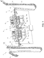
- number 1 indicates as a whole a unit for applying a plurality of opening devices 2 (only schematically shown) onto respective predetermined areas of a web 4 of packaging material, in particular a web 4 in the form of a strip initially wound about a respective reel (not shown) arranged upstream of unit 1.
- the packaging material is intended to form a plurality of packages (not shown) adapted to contain a pourable product, preferably a pourable food product.
- the packaging material has a multilayer structure (not shown) and comprises a layer of fibrous material, e.g. paper, covered on both sides with respective lamination layers of heat-seal plastic material, e.g. polyethylene.
- the packaging material also comprises a layer of gas-and-light barrier material, e.g. aluminum foil or ethylene vinyl alcohol (EVOH) film, which is superimposed on a layer of heat-seal plastic material, and is in turn covered with another layer of heat-seal plastic material, the latter forming the inner face of the package eventually contacting the pourable product.
- gas-and-light barrier material e.g. aluminum foil or ethylene vinyl alcohol (EVOH) film
- Packages are formed starting from a tube (not shown) of packaging material.
- the tube is formed in known manner downstream of unit 1 by longitudinally folding and sealing web 4.
- the tube of packaging material is then filled with the food product , and is sealed and cut along equally spaced cross sections to form a number of pillow packs (not shown), which are then transferred to a folding unit where they are folded mechanically to form respective packages.
- the predetermined areas of web 4 are defined by removable portions of web 4.
- removable portions are defined by so-called pre-laminated holes 3, i.e. holes (or openings) formed through the base layer only and covered by the other lamination layers of the packaging material, so that each hole is sealed by a respective sheet cover portion (known per se and neither shown nor described in detail).
- pre-laminated holes i.e. holes (or openings) formed through the base layer only and covered by the other lamination layers of the packaging material, so that each hole is sealed by a respective sheet cover portion (known per se and neither shown nor described in detail).
- pre-laminated holes 3 are arranged along web 4, i.e. in a lengthwise direction of web 4, in respective positions equally spaced from one another, except for the inevitable tolerance errors.
- unit 1 is a molding unit for molding, in particular for injection molding, a plurality of opening devices 2 onto respective pre-laminated holes 3.
- unit 1 substantially comprises:
- feeding group 5 stepwise feeds, in use and one after the other, a plurality of portions 7 of web 4, each comprising a predetermined number of pre-laminated holes 3, in a manner that will be described in the following.
- each portion 7 includes, relative to path P, at least:
- pre-laminated holes 3a, 3b, 3c of each portion 7 are upstream of pre-laminated holes 3d, 3e, 3f of the same portion 7 (i.e. of relative stretch 10), along path P.
- pre-laminated hole 3b is arranged centrally with respect to, and at the same distance from, pre-laminated holes 3a and 3c; similarly, pre-laminated hole 3e is arranged centrally with respect to, and at the same distance from, pre-laminated holes 3d and 3f.
- portion 7 of web 4 onto which opening devices 2 have to be applied in particular molded, by means of molding station 6.
- portion 7 the structural and functional features disclosed hereinafter for such portion 7 are equally applicable to all portions 7 of web 4 to be treated by unit 1.
- molding station 6 comprises:
- molds 11a, 11b, 11c, 12a, 12b, 12c are arranged at respective desired positions along path P.
- molds 11a, 11b, 11c, 12a, 12b, 12c are fixed at such respective desired positions thereby defining respective axes A, B, C, D, E, F fixed along path P, such axes being transversal, in particular orthogonal to path P.
- axes A, B, C are orthogonal to stretch 8
- axes D, E, F are orthogonal to stretch 10, when portion 7 is treated, in use, by molding station 6.
- first group 11 of molds could comprise only one of molds 11a, 11b or 11c and second group 12 of molds could comprise only one of molds 12a, 12b or 12c.
- each mold 11a, 11b, 11c, 12a, 12b, 12c is configured to injection mold a respective opening device 2 onto a respective pre-laminated hole 3a, 3b, 3c, 3d, 3e, 3f of portion 7, in correspondence of axes A, B, C, D, E, F, respectively.
- each pre-laminated hole 3a, 3b, 3c, 3d, 3e, 3f is associated to a respective axis G, H, I, L, M, N movable along path P and at which the respective opening device 2 should be injected, according to nominal operation of unit 1.
- the distance between axes A, B; B, C; D, E; E, F measured parallel to path P equals the predetermined nominal distance between axes G, H; H, I; L, M; M, N at which the pre-laminated holes 3 are nominally arranged onto web 4.
- portion 7 of web 4 has to be positioned, by means of feeding group 5, in a way that each one of the axes G, H, I, L, M, N coincide with the corresponding one of the axes A, B, C, D, E, F, respectively.
- feeding group 5 comprises:
- advancing device 13 controls the positioning of the "central" pre-laminated hole 3e to minimize the tolerance error relative to the adjacent pre-laminated holes 3d and 3f, thereby avoiding the chaining of such tolerance error.
- adjusting device 14 controls the positioning of the "central" pre-laminated hole 3b to minimize the tolerance error relative to the adjacent pre-laminated holes 3a and 3c, thereby avoiding the chaining of such tolerance error.
- advancing device 13 could control the positioning of any one of the pre-laminated holes 3d, 3e, 3f of portion 7 and adjusting device 14 could control the positioning of any one of the pre-laminated holes 3a, 3b, 3c of portion 7.
- advancing device 13 is defined by a roller arranged downstream of second group 12 of molds along path P, drivable by a relative non-shown actuator, e.g. a stepper motor, supporting, in use, web 4 and cooperating in contact with web 4 to stepwise advance web 4 along path P.
- a relative non-shown actuator e.g. a stepper motor
- advancing device 13 is configured to pull web 4 from the relative storage reel by applying a pulling tension to web 4, thereby determining the advancement of web 4 along path P.
- unit 1 further comprises:
- web 4 comprises a plurality of magnetic markers (known per se and not shown), each associated with a respective pre-laminated hole 3, in particular with the position of such respective pre-laminated hole 3.
- first sensor 15 and second sensor 16 are configured to be magnetically coupled with, i.e. to "sense", the magnetic markers in order to detect the positions of pre-laminated holes 3.
- first sensor 15 and second sensor 16 could be optical sensors, configured to optically detect the positions of pre-laminated holes 3.
- Feeding group 5 further comprises a tensioning device 100 arranged upstream of first group 11 of molds and configured to put and maintain under tension the web 4 by exerting a pulling action on web 4 in a direction opposite to the advancing direction of web 4 along path P.
- a tensioning device 100 arranged upstream of first group 11 of molds and configured to put and maintain under tension the web 4 by exerting a pulling action on web 4 in a direction opposite to the advancing direction of web 4 along path P.
- advancing device 13 advances, in use, web 4 along path P by overcoming the tensioning force of tensioning device 100.
- pre-laminated hole 3b is in a non-nominal position for which axis H is downstream of axis B with respect to the advancing direction of web 4 along path P, then adjusting device 14 releases web 4 on the basis of calculated value E2 and, at the same time, tensioning device 100 pulls back web 4, according to a manner described in the following.
- tensioning device 100 pulls back web 4, according to a manner described in the following.
- values E1 and E2 are conveniently calculated as absolute values of the differences of the positions correlated with signals S1, S3 and S2, S4, respectively.
- the distance between the first group of molds and the second group of molds cannot be reduced in an unlimited manner, due to the space occupied by the roller actuator interposed between the two groups of molds.
- unit 1 comprises a buffer portion 18 arranged along path P, downstream of first group 11 of molds and upstream of second group 12 of molds, in particular downstream of mold 11c and upstream of mold 12a, and configured to include and/or accumulate a web portion 19 having a number of pre-laminated holes 3 which is an integer multiple of the number of molds 11a, 11b, 11c, 12a, 12b, 12c of molding station 6.
- buffer portion 18 is an accumulation portion defining an accumulation path within path P, where, cyclically and one after the other, web portions 19 of web 4 are accumulated, i.e. included at any given cycle, before being fed to second group 12 of molds.
- portion 7 comprises a third stretch arranged downstream of stretch 8 and upstream of stretch 10 and defined by web portion 19.
- web portion 19 comprises a number of pre-laminated holes 3 which is, conveniently, an integer multiple of the number of molds of the molding station 6.
- web portion 19 has preferably six pre-laminated holes 3.
- web portion 19 has preferably twelve, eighteen, etc. pre-laminated holes 3.
- N k * m .
- adjusting device 14 is arranged at buffer portion 18.
- adjusting device 14 is arranged in a position so that a first stretch 19a of web portion 19 is located downstream of adjusting device 14 and a second stretch 19b of web portion 19 is located upstream of adjusting device 14, relative to path P.
- second stretch 19b is adjacent and connected to stretch 8, and therefore is adjacent to pre-laminated holes 3a, 3b, 3c, while first stretch 19a is adjacent and connected to stretch 10, and therefore is adjacent to pre-laminated holes 3d, 3e, 3f.
- first stretch 19a defines a first half of web portion 19 and second stretch 19b defines a second half of web portion 19.
- both first stretch 19a and second stretch 19b include three pre-laminated holes 3, since web portion 19 has six pre-laminated holes 3.
- Adjusting device 14 is configured to control a movement of second stretch 19b along path P to position pre-laminated hole 3b at the relative desired position on the basis of value E2, while leaving first stretch 19a substantially stationary, in particular stationary, along path P.
- advancing device 13 is configured to position first stretch 19a at least while adjusting device 1 controls the movement of second stretch 19b along path P, therefore substantially avoiding, in particular avoiding, a movement of the already-positioned first stretch 19a.
- tensioning device 100 maintains under tension web 4 by pulling second stretch 19b in a direction opposite to the advancing direction of web 4 along path P.
- the above configuration allows to position both pre-laminated hole 3e and pre-laminated hole 3b at the respective desired positions, thereby minimizing any eventual tolerance error between pre-laminated hole 3e and pre-laminated holes 3d and 3f; and between pre-laminated hole 3b and pre-laminated holes 3a and 3c.
- the distance between first group 11 of molds and second group 12 of molds, in particular between molds 11c and 12a is not anymore linked to the nominal distance between consecutive pre-laminated holes 3, thanks to the presence of buffer portion 18.
- second group 12 of molds can be positioned at any convenient desired distance from first group 11 of molds. Accordingly, the distance between pre-laminated holes 3 can be further reduced.
- unit 1 can be used to produce smaller packages, since the distance between each pre-laminated hole 3 of web 4 is reduced.
- molds 11a, 11b, 11c are configured to apply opening devices 2 to the three pre-laminated holes 3 of first stretch 19a, whereas molds 12a, 12b, 12c are configured to apply opening devices 2 to the three pre-laminated holes 3 of second stretch 19b, as shown in Figures 3a and 3b .
- opening devices 2 are molded onto first stretch 19a and during a subsequent step, opening devices 2 are molded onto second stretch 19b, for each portion 7 of web 4.
- adjusting device 14 comprises a rotatable member 20 which supports, in use, web 4 and which is rotatable eccentrically about a fixed longitudinal axis X transversal, in particular orthogonal, to path P, on the basis of value E2, to push or release web portion 19 to position pre-laminated hole 3b at the relative desired position (i.e. so that axis H coincides with axis B).
- adjusting device 14 comprises a known actuator, for example a stepper motor (not shown) configured to be controlled by control unit 17 on the basis of value E2, in order to rotate a shaft (not shown) about axis X.
- a known actuator for example a stepper motor (not shown) configured to be controlled by control unit 17 on the basis of value E2, in order to rotate a shaft (not shown) about axis X.
- Rotatable member 20 is coupled eccentrically to the above-mentioned shaft (in a manner known and not shown in detail), and therefore is eccentrically arranged relative to axis X, so that a rotation of such shaft about axis X drives a translation movement of rotatable member 20 towards or away from web portion 19.
- rotatable member 20 drags or releases, in use, second stretch 19b along path P.
- the dragging or releasing of second stretch 19b combined with the tensioning imparted by tensioning device 100, determines the adjustment of the position of pre-laminated hole 3b along path P, on the basis of value E2 ( Figures 3a and 3b ) .
- the above dragging or releasing also determines the positioning of axes G and I of pre-laminated holes 3a and 3c with respect to axes A and C of molds 11a and 11c, within the acceptable tolerance errors.
- unit 1 The operation of unit 1 is described hereinafter with reference to Figures 3a and 3b and starting from a condition in which advancing device 13 has already nominally positioned pre-laminated hole 3e so that axis M coincides with axis E, on the basis of the calculated value E1.
- first group 11 of molds has already injected three opening devices 2 on three corresponding pre-laminated holes 3 of first stretch 19a of the web portion 19 accumulated in buffer portion 18.
- control unit 17 calculates value E2. If such value E2 is different from zero (as shown in Figure 3a ), control unit 17 drives adjusting device 14, in particular rotatable member 20, to act on second stretch 19b and move second stretch 19b along path P, while leaving first stretch 19a substantially stationary, preferably stationary, along path P. The amplitude of the movement will depend on the calculated value E2. At the same time, tensioning device 100 maintains under tension web 4 and in particular second stretch 19b. If needed, tensioning device 100 also pulls back second stretch 19b in a direction opposite the advancing direction along path P. Also, the amplitude of this movement will depend on the position of advancing device 14 (rotatable member 20), i.e. on the calculated value E2.
- pre-laminated hole 3b can be positioned at the relative desired injection position under mold 12b, i.e. axis H coincides with axis B (as shown in Figure 3b ).
- first group 11 of molds injects opening devices 2 onto pre-laminated holes 3a, 3b, 3c (within the acceptable tolerance errors) and second group 12 of molds injects opening devices 2 onto pre-laminated holes 3d, 3e, 3f (within the acceptable tolerance errors).
- the pre-laminated holes 3 of the second stretch 19b of web portion 19 will be injected with plastic material by the second group 12 of molds during the next cycle, i.e. injection cycle.
- unit 1 ensures that the tolerance errors are not propagated and thereby minimized along path P, while, at the same time allowing a reduction of the distance between pre-laminated holes 3 of web 4, since the distance between first group 11 of molds and second group 12 of molds, in particular between molds 11c and 12a is not anymore linked to the distance between pre-laminated holes 3, thanks to the presence of buffer portion 18.
- opening devices 2 could be of different type and, accordingly, the application station could entail a different kind of application than molding.
- opening devices 2 could comprise a patch defined by a small sheet of heat-seal plastic material, which is heat sealed over a respective hole on the side of web 4 eventually forming the inner side of the packages; and a pull-off tab applied to the opposite side of the packaging material and heat sealed to the patch.
- the patch and the tab adhere to one another, so that, when the tab is pulled off, the portion of the patch heat sealed to it is also removed to uncover the hole (and open the package).
Landscapes
- Injection Moulding Of Plastics Or The Like (AREA)
- Containers And Plastic Fillers For Packaging (AREA)
- Absorbent Articles And Supports Therefor (AREA)
Applications Claiming Priority (1)
| Application Number | Priority Date | Filing Date | Title |
|---|---|---|---|
| EP19208835 | 2019-11-13 |
Publications (1)
| Publication Number | Publication Date |
|---|---|
| EP3822071A1 true EP3822071A1 (fr) | 2021-05-19 |
Family
ID=68583073
Family Applications (1)
| Application Number | Title | Priority Date | Filing Date |
|---|---|---|---|
| EP20204975.5A Pending EP3822071A1 (fr) | 2019-11-13 | 2020-10-30 | Unité et procédé d'application de dispositifs d'ouverture sur une bande de matériau d'emballage |
Country Status (5)
| Country | Link |
|---|---|
| US (1) | US20220355562A1 (fr) |
| EP (1) | EP3822071A1 (fr) |
| JP (1) | JP2023503837A (fr) |
| CN (1) | CN114728484A (fr) |
| WO (1) | WO2021094113A1 (fr) |
Citations (3)
| Publication number | Priority date | Publication date | Assignee | Title |
|---|---|---|---|---|
| WO2007007379A1 (fr) * | 2005-07-08 | 2007-01-18 | Mitsubishi Denki Kabushiki Kaisha | Dispositif de traitement et procédé de traitement |
| EP2357138A1 (fr) | 2010-02-12 | 2011-08-17 | Tetra Laval Holdings & Finance S.A. | Dispositif et procédé pour alimenter une bande de matériau d'emballage |
| EP2848399A1 (fr) | 2013-09-13 | 2015-03-18 | Tetra Laval Holdings & Finance SA | Unité et procédé permettant de mettre en oeuvre une première puis une deuxième opération sur une bande |
Family Cites Families (6)
| Publication number | Priority date | Publication date | Assignee | Title |
|---|---|---|---|---|
| SE8600365L (sv) * | 1986-01-28 | 1987-07-29 | Tetra Pak Int | Sett och anordning for frammatning av en materialbana |
| US5000725A (en) * | 1988-11-07 | 1991-03-19 | Fmc Corporation | Bi-directional registration of servo indexed webs |
| BR9603516A (pt) * | 1995-08-22 | 1998-05-19 | Fmc Corp | Processo de corrigir o avanço de segmentos de material e de sacos que são formados a partir de uma folha contínua de material e sistema de correção para corrigir o avanço de segmentos de material |
| DE19913855A1 (de) * | 1999-03-26 | 2000-09-28 | Focke & Co | Verfahren und Vorrichtung zum Bedrucken von Zuschnitten |
| SE521876C2 (sv) * | 1999-12-22 | 2003-12-16 | Tetra Laval Holdings & Finance | Flerstegsenhet för bearbetning av ett banformat förpackningsmaterial i en maskin för förpackning av livsmedel |
| US9044974B1 (en) * | 2014-02-18 | 2015-06-02 | Xerox Corporation | System and method for online web control in a tandem web printing system |
-
2020
- 2020-10-30 US US17/765,010 patent/US20220355562A1/en active Pending
- 2020-10-30 WO PCT/EP2020/080577 patent/WO2021094113A1/fr active Application Filing
- 2020-10-30 JP JP2022527920A patent/JP2023503837A/ja active Pending
- 2020-10-30 EP EP20204975.5A patent/EP3822071A1/fr active Pending
- 2020-10-30 CN CN202080078837.1A patent/CN114728484A/zh active Pending
Patent Citations (3)
| Publication number | Priority date | Publication date | Assignee | Title |
|---|---|---|---|---|
| WO2007007379A1 (fr) * | 2005-07-08 | 2007-01-18 | Mitsubishi Denki Kabushiki Kaisha | Dispositif de traitement et procédé de traitement |
| EP2357138A1 (fr) | 2010-02-12 | 2011-08-17 | Tetra Laval Holdings & Finance S.A. | Dispositif et procédé pour alimenter une bande de matériau d'emballage |
| EP2848399A1 (fr) | 2013-09-13 | 2015-03-18 | Tetra Laval Holdings & Finance SA | Unité et procédé permettant de mettre en oeuvre une première puis une deuxième opération sur une bande |
Also Published As
| Publication number | Publication date |
|---|---|
| JP2023503837A (ja) | 2023-02-01 |
| US20220355562A1 (en) | 2022-11-10 |
| CN114728484A (zh) | 2022-07-08 |
| WO2021094113A1 (fr) | 2021-05-20 |
Similar Documents
| Publication | Publication Date | Title |
|---|---|---|
| RU2636325C2 (ru) | Установка для нанесения открывных устройств на герметично закрытые упаковки пищевых продуктов | |
| EP3081497B1 (fr) | Machine d'emballage et procédé de production d'emballages à partir d'un matériau d'emballage | |
| RU2555582C2 (ru) | Устройство и способ для подачи полотна упаковочного материала | |
| EP3438007B1 (fr) | Procédé et appareil d'application d'une bande d'étanchéité sur une toile de matériau d'emballage | |
| US9505189B2 (en) | Apparatus for forming a plurality of flexible pouches from a continuous web of film | |
| MX2011005301A (es) | Unidad para aplicacion de dispositivos de abertura sobre empaques de productos alimenticios que se pueden verter en un tubo del material de empaque. | |
| US7175582B2 (en) | Method and apparatus for registering fastener tape in packaging machine | |
| JP6499181B2 (ja) | ウェブに第1の処理および第2の処理を施すためのユニットおよび方法 | |
| EP3822071A1 (fr) | Unité et procédé d'application de dispositifs d'ouverture sur une bande de matériau d'emballage | |
| JP4744780B2 (ja) | 包装材料のウェブを加工処理するためのユニット | |
| EP1110867A1 (fr) | Unité à étages multiples pour traiter une bande de matériau d'emballage dans une machine d'emballage de produits alimentaires | |
| EP3141488B1 (fr) | Machine d'emballage de production d'emballages à partir d'une feuille de matériau d'emballage | |
| US11535475B2 (en) | Web alignment device, a packaging machine having a web alignment device and a splicing method | |
| EP3517467B1 (fr) | Unité de magasin destinée à une machine d'emballage, machine d'emballage comportant une unité de magasin et procédé pour charger une unité de magasin |
Legal Events
| Date | Code | Title | Description |
|---|---|---|---|
| PUAI | Public reference made under article 153(3) epc to a published international application that has entered the european phase |
Free format text: ORIGINAL CODE: 0009012 |
|
| STAA | Information on the status of an ep patent application or granted ep patent |
Free format text: STATUS: THE APPLICATION HAS BEEN PUBLISHED |
|
| AK | Designated contracting states |
Kind code of ref document: A1 Designated state(s): AL AT BE BG CH CY CZ DE DK EE ES FI FR GB GR HR HU IE IS IT LI LT LU LV MC MK MT NL NO PL PT RO RS SE SI SK SM TR |
|
| STAA | Information on the status of an ep patent application or granted ep patent |
Free format text: STATUS: REQUEST FOR EXAMINATION WAS MADE |
|
| 17P | Request for examination filed |
Effective date: 20211119 |
|
| RBV | Designated contracting states (corrected) |
Designated state(s): AL AT BE BG CH CY CZ DE DK EE ES FI FR GB GR HR HU IE IS IT LI LT LU LV MC MK MT NL NO PL PT RO RS SE SI SK SM TR |