EP3821989B1 - Online automation measurement system for claw-pole overall magnetic property - Google Patents
Online automation measurement system for claw-pole overall magnetic property Download PDFInfo
- Publication number
- EP3821989B1 EP3821989B1 EP19833721.4A EP19833721A EP3821989B1 EP 3821989 B1 EP3821989 B1 EP 3821989B1 EP 19833721 A EP19833721 A EP 19833721A EP 3821989 B1 EP3821989 B1 EP 3821989B1
- Authority
- EP
- European Patent Office
- Prior art keywords
- claw
- pole
- magnetic
- measured
- poles
- Prior art date
- Legal status (The legal status is an assumption and is not a legal conclusion. Google has not performed a legal analysis and makes no representation as to the accuracy of the status listed.)
- Active
Links
Images


Classifications
-
- G—PHYSICS
- G01—MEASURING; TESTING
- G01R—MEASURING ELECTRIC VARIABLES; MEASURING MAGNETIC VARIABLES
- G01R33/00—Arrangements or instruments for measuring magnetic variables
- G01R33/12—Measuring magnetic properties of articles or specimens of solids or fluids
- G01R33/1253—Measuring galvano-magnetic properties
-
- B—PERFORMING OPERATIONS; TRANSPORTING
- B07—SEPARATING SOLIDS FROM SOLIDS; SORTING
- B07C—POSTAL SORTING; SORTING INDIVIDUAL ARTICLES, OR BULK MATERIAL FIT TO BE SORTED PIECE-MEAL, e.g. BY PICKING
- B07C5/00—Sorting according to a characteristic or feature of the articles or material being sorted, e.g. by control effected by devices which detect or measure such characteristic or feature; Sorting by manually actuated devices, e.g. switches
- B07C5/34—Sorting according to other particular properties
- B07C5/344—Sorting according to other particular properties according to electric or electromagnetic properties
-
- B—PERFORMING OPERATIONS; TRANSPORTING
- B07—SEPARATING SOLIDS FROM SOLIDS; SORTING
- B07C—POSTAL SORTING; SORTING INDIVIDUAL ARTICLES, OR BULK MATERIAL FIT TO BE SORTED PIECE-MEAL, e.g. BY PICKING
- B07C2501/00—Sorting according to a characteristic or feature of the articles or material to be sorted
- B07C2501/0063—Using robots
Definitions
- This invention relates to a technology in the field of magnetic performance measurement for generators, in particular to an online automatic measuring system of the magnetic properties for claw-pole.
- Claw-pole generator is the most commonly used type of automobile generator.
- Two claw-poles cooperate with each other to form the magnetic poles of the rotor. They are magnetized under the excitation of the magnetizing winding and then generate a strong magnetic field. The rotor is rotated and cut the exitation coil to induce voltage and generate electricity. Improving the magnetic properties of claw-pole parts can directly improve the generation efficiency of claw-pole generator at the same rotation rate.
- there are many different manufacturing processes and raw materials for claw-pole How to measure and evaluate the overall magnetic properties of claw-pole and guide the optimization of its manufacturing process and raw material composition is of great significance. Therefore, it is urgent to develop a measuring system of the magnetic properties for claw-pole.
- Chinese Patent Application CN-A-104515959 discloses equipment and a method for automatically detecting the magnetic flux of special magnetic steel for an electronic power motor of a steering wheel of an automobile.
- the equipment consists of a detection waiting platform, a detection platform, a rotary table and a charging hopper frame which are sequentially arranged, wherein a discharging cylinder pushing rod is arranged at one end of the detection waiting platform, and a detection waiting movement station is arranged at the other end of the detection waiting platform; a magnetic steel discharging hopper frame is further arranged on the detection waiting platform and is positioned between the discharging cylinder pushing rod and the detection waiting movement station; a movement manipulator is arranged on the detection platform; a vacuum suction cup is arranged below the material taking end of the movement manipulator; a charging pushing rod and six graded material baskets are arranged on the rotary table; the material baskets and the charging hopper frame are correspondingly placed.
- the invention proposes an online automatic measurement system of the overall magnetic performance of the claw-pole, which greatly improves the detection efficiency of the claw-pole parts through the automatic detection process.
- the invention relates to an online automatic detection system for the overall magnetic properties of claw-poles according to independent claim 1, which in particular includes the feeding part, the measuring unit for the overall magnetic properties of claw-poles, the discharging part and the manipulator arranged therein.
- the manipulator receives the operation instructions from the control unit to grab the claw-poles to be measured on the feeding part and move them out of the measuring unit in turn.
- the measuring unit for the overall magnetic properties of claw-poles outputs control power to the measuring unit, receives the induced current of the measured claw-pole and outputs the test results to the control unit according to the instructions from the control unit.
- the measuring unit for the overall magnetic properties of claw-poles includes a support base, a winding ferrule and a claw-pole handling device arranged on the support base from inside to outside and a DC magnetic performance measurement instrument.
- the measured claw-pole is positioned and detached from the support base through the handling device.
- the winding ferrule is provided with measuring coil and magnetizing winding connected with the DC magnetic performance measurement instrument, and the measuring coil is located inside the measured claw-pole.
- a conducting ring is set outside the measured claw-pole to form a magnetic field loop with the measured claw-pole.
- the DC magnetic performance measuring instrument outputs control power to the measuring unit for the overall magnetic properties of claw-poles according to the instructions of the control unit.
- the magnetizing winding receives the excitation voltage from the DC magnetic performance measuring instrument, and the measuring coil generates and transmits the induced current to the DC magnetic performance measuring instrument.
- the output excitation current is recorded by the DC magnetic performance measuring instrument.
- the detected induction current is converted to the induction voltage, and the magnetic induction intensity is calculated through integrating the voltage in the time domain. Then, the whole magnetization curve of the claw-pole part to be measured is obtained to characterize the magnetic conductivity of the claw-pole part.
- the induction current is calculated by the electronic integrator, and then the induction magnetic flux ⁇ induced in the coil is calculated.
- the claw-pole handling device comprises a positioning axis set inside the support base and a hydraulic cylinder connected with the positioning axis.
- a magnetic conducting pad is arranged on the positioning axis, which is located between the support base and the measured claw-pole, and the positioning and detachment of the measured claw-pole and the support base are realized by driving the lifting of the positioning axis through the hydraulic cylinder.
- the positioning axis is a ladder-shaped structure for ensuring the coaxiality between the measured claw-pole and the central boss of the support base.
- the joint surface of the large end and the small end of the positioning axis contacts the lower end surface of the ring magnetic conducting pad, and the diameter of the large end matches the inner diameter of the central hole of the measured claw-pole, and the diameter of the small end matches the inner diameter of the ring magnetic conducting pad.
- the outer diameter of the magnetic conducting pad is smaller than that of the center boss of the support base and the inner diameter is smaller than that of the inner hole of the measured claw-pole.
- the magnetic conducting pad has a taper preferably to facilitate assembly and disassembly.
- An annular sleeve is arranged on the contact surface between the positioning axis and the measured claw-pole.
- the inner diameter of the annular sleeve matches the outer diameter of the small end of the positioning axis and the outer diameter matches the inner diameter of the central hole of the measured claw-pole.
- the winding ferrule is provided with upper and lower spaces.
- the smaller upper space is used for winding measuring coil s, and the larger lower space is used for winding magnetizing windings.
- the inner diameter of the winding ferrule in the lower end is in clearance fit with the outer diameter of the center boss of the support base.
- the support base is set with a magnetic isolation pad in the bottom, and the thickness is larger than 1.5 times of the support base thickness.
- the feeding part adopts, but is not limited to, a conveyor belt for carrying the claw-pole to be measured.
- the discharging part includes two conveyor belts for carrying qualified claw-poles and unqualified claw-poles respectively, and the conveyor belt with qualified claw-poles coincides with the starting end of the conveyor belt with defective claw-poles.
- the manipulator is preferred to have overturning function.
- the manipulator clamps the claw-pole to be measured from the feeding conveyor belt into the measuring device of the magnetic performance for the claw-pole in turn by receiving the instructions from the control unit, and waits for the signal from the control unit to clamp the tested claw-pole to the discharging conveyor belt.
- the control unit comprises the central controller, the manipulator controller and driver, the conveyor belt controller and driver, the claw-pole handling controller and driver.
- the central controller is respectively connected with the manipulator controller, the DC magnetic performance measuring instrument, the conveyor belt controller and the claw-pole handling controller and sends out control signals to them.
- the DC magnetic performance measuring instrument transmits the measurement results to the central controller to achieve orderly detection and classification.
- the invention realizes the non-destructive detection of claw-pole parts. It can be matched with the existing production line of claw-pole parts to realize automatic online detection.
- Fig. 1 presents the online automatic measuring system of the magnetic properties for claw-pole described in this embodiment, which includes feeding conveyor belt 1 as feeding part, manipulator 3 with overturning function, claw-pole handling device 4, control unit 5, measuring unit for the overall magnetic properties of claw-poles 8, unqualified products output belt 10 and discharging conveyor belt 12 as discharging part.
- the manipulator receives the operation instructions from the control unit to grab the claw-poles to be measured on the feeding part and move them out of the measuring unit in turn.
- the measuring unit for the overall magnetic properties of claw-poles outputs control power to the measuring unit, receives the induced current of the claw-pole to be measured and outputs the test results to the control unit according to the instructions from the control unit.
- the measuring unit for the overall magnetic properties of claw-poles 8 includes a support base 8-2 with a central circular boss, magnetizing winding 8-3 and measuring coil 8-5 arranged on the winding ferrule 8-8 and connected with the DC magnetic performance measurement instrument 6, conducting ring 8-4 set outside the claw-pole to be measured 9, and claw-pole handling device.
- the total height of the conducting ring 8-4 is 1.1 ⁇ 1.2 times that of the claw-pole part to be measured.
- the conducting ring 8-4 is provided with a step structure in the bottom for matching with the support base.
- the conducting ring is made of a ferromagnetic material with high permeability and high saturation magnetic induction intensity.
- the function of the conducting ring 8-4 is mainly to form a magnetic field loop with the claw-pole to be measured.
- the diameter of the intermediate through hole in the support base 8-2 matches the diameter of the central hole of the claw-pole part.
- the diameter of the central boss is 3 ⁇ 5mm larger than that of the claw-pole boss.
- the thickness t 1 of the outer ring matches the thickness of the conducting ring, and the thickness t 2 of the bottom is more than 1.5 times that of the outer ring.
- the support base is connected with the bottom magnetic isolation pad with bolts.
- the support base is made of ferromagnetic material with high permeability and saturated magnetic induction intensity.
- the taper of the magnetic conducting pad 8-7 is 8°.
- the winding ferrule 8-8 is provided with upper and lower spaces.
- the smaller upper space is used for winding measuring coil s, and the larger lower space is used for winding magnetizing windings.
- the inner diameter of the winding ferrule in the lower end is in clearance fit with the outer diameter of the center boss of the support base, and the winding ferrule is made of paramagnetic material.
- the winding method of the coil on the winding ferrule 8-8 is as follows.
- the copper wire is uniformly wound onto the lower space in the same direction to work as the magnetizing winding, and wire is wound on the upper space as the measuring coil.
- the turns number of the magnetizing winding 8-3 is 1.1 ⁇ 1.2 times as many as the winding turns number of the magnetizing winding needed for the claw-pole to be measured in the actual use of the motor.
- the measuring range is set to 1500 ampere turns.
- the magnetizing winding in the claw-pole generator rotor corresponding to the claw-pole to be measured is 360 turns, so in order to be safe, the magnetizing winding on the winding ferrule is set to be 400 turns.
- the maximum magnetic flux range of the DC magnetic performance measuring instrument is 0.8 mwb, the maximum magnetic flux density of the claw-pole to be measured is estimated to be 2.1T, and the cross-sectional area of the claw-pole boss is 1900 mm 2 , so the maximum turns number of the measuring coil is calculated to be 2.5 turns. In order to ensure the safety of the measuring instrument, the turns number of the measuring coil is selected as 2 turns.
- the excitation current output by DC magnetic performance measurement instrument is set to be 3.75A.
- the test steps of the device are as follows: During testing, the relevant parameters in DC magnetic performance measuring instrument 6 are set according to the type of the claw-pole to be tested, including effective cross-section area 1900mm 2 , magnetizing winding turns 400 turns and measuring coil turns 2 turns.
- the claw-pole 2 to be measured is placed in the positioning groove for claw-pole of the feeding conveyor belt 1.
- the driver of hydraulic cylinder 4 of the claw-pole handling device is reset.
- the classification scheme of measurement results is set up in control unit 5.
- the manipulator 3 with overturning function is reset to the initial position far from the magnetic performance measuring device, and then the whole system is opened to start operation.
- Step 1 The manipulator 3 with overturning function clamps the claw-pole 2 to be measured from the predetermined position of the feeding conveyor belt 1 and puts it into the measuring unit for the overall magnetic properties of claw-poles 8 with ejection mechanism.
- the manipulator 3 with overturning function resets to the initial position and transmits the signal to the control unit 5. Meanwhile, the feeding conveyor belt sends the next claw-pole to the predetermined position.
- Step 2 The control unit 5 receives the signal from the manipulator 3 with overturning function and opens the DC magnetic performance measuring instrument 6.
- the claw-poles to be measured are demagnetized and measured in DC magnetic performance measuring instrument 6 in turn. Up to the end of the measurement, the DC magnetic performance measuring instrument 6 transmits the measurement results to the control unit 5.
- Step 3 The control unit 5 receives the measurement results and sends signals to the manipulator 3 with overturning function and hydraulic cylinder driver 4 of ejection mechanism according to the classification scheme set by the system.
- Step 4 The driver 4 of the claw-pole handling device receives the signal from the control unit, drives the hydraulic cylinder and ejects the measured claw-pole.
- Step 5 The control unit 5 receives the feedback signal from driver 4, and controls the manipulator 3 to clamp the measured claw-poles to the predetermined position of the discharging conveyor belt 12 or directly put them into the conveyor belt 10 for unqualified products. Then the manipulator 3 is reset, and the qualified products are delivered by the discharging conveyor belt to the next production process.
- the measurement results are shown in Table 1.
Landscapes
- Physics & Mathematics (AREA)
- Condensed Matter Physics & Semiconductors (AREA)
- General Physics & Mathematics (AREA)
- Measuring Magnetic Variables (AREA)
- Investigating Or Analyzing Materials By The Use Of Magnetic Means (AREA)
- Manufacture Of Motors, Generators (AREA)
Description
- This invention relates to a technology in the field of magnetic performance measurement for generators, in particular to an online automatic measuring system of the magnetic properties for claw-pole.
- Claw-pole generator is the most commonly used type of automobile generator. Two claw-poles cooperate with each other to form the magnetic poles of the rotor. They are magnetized under the excitation of the magnetizing winding and then generate a strong magnetic field. The rotor is rotated and cut the exitation coil to induce voltage and generate electricity. Improving the magnetic properties of claw-pole parts can directly improve the generation efficiency of claw-pole generator at the same rotation rate. In practice, there are many different manufacturing processes and raw materials for claw-pole. How to measure and evaluate the overall magnetic properties of claw-pole and guide the optimization of its manufacturing process and raw material composition is of great significance. Therefore, it is urgent to develop a measuring system of the magnetic properties for claw-pole. For industrial mass production, the quality of claw-pole parts can be controlled more effectively by realizing online automatic measurement.
Chinese Patent ApplicationCN-A-104515959 discloses equipment and a method for automatically detecting the magnetic flux of special magnetic steel for an electronic power motor of a steering wheel of an automobile. The equipment consists of a detection waiting platform, a detection platform, a rotary table and a charging hopper frame which are sequentially arranged, wherein a discharging cylinder pushing rod is arranged at one end of the detection waiting platform, and a detection waiting movement station is arranged at the other end of the detection waiting platform; a magnetic steel discharging hopper frame is further arranged on the detection waiting platform and is positioned between the discharging cylinder pushing rod and the detection waiting movement station; a movement manipulator is arranged on the detection platform; a vacuum suction cup is arranged below the material taking end of the movement manipulator; a charging pushing rod and six graded material baskets are arranged on the rotary table; the material baskets and the charging hopper frame are correspondingly placed. - In view of the defect that the existing technology can not realize the online automatic measurement of the overall magnetic performance of the claw-pole, the invention proposes an online automatic measurement system of the overall magnetic performance of the claw-pole, which greatly improves the detection efficiency of the claw-pole parts through the automatic detection process.
- The invention is realized by the following technical scheme:
- The invention relates to an online automatic detection system for the overall magnetic properties of claw-poles according to independent claim 1, which in particular includes the feeding part, the measuring unit for the overall magnetic properties of claw-poles, the discharging part and the manipulator arranged therein. The manipulator receives the operation instructions from the control unit to grab the claw-poles to be measured on the feeding part and move them out of the measuring unit in turn. The measuring unit for the overall magnetic properties of claw-poles outputs control power to the measuring unit, receives the induced current of the measured claw-pole and outputs the test results to the control unit according to the instructions from the control unit.
- The measuring unit for the overall magnetic properties of claw-poles includes a support base, a winding ferrule and a claw-pole handling device arranged on the support base from inside to outside and a DC magnetic performance measurement instrument. The measured claw-pole is positioned and detached from the support base through the handling device. The winding ferrule is provided with measuring coil and magnetizing winding connected with the DC magnetic performance measurement instrument, and the measuring coil is located inside the measured claw-pole. A conducting ring is set outside the measured claw-pole to form a magnetic field loop with the measured claw-pole. The DC magnetic performance measuring instrument outputs control power to the measuring unit for the overall magnetic properties of claw-poles according to the instructions of the control unit. The magnetizing winding receives the excitation voltage from the DC magnetic performance measuring instrument, and the measuring coil generates and transmits the induced current to the DC magnetic performance measuring instrument. The output excitation current is recorded by the DC magnetic performance measuring instrument. The detected induction current is converted to the induction voltage, and the magnetic induction intensity is calculated through integrating the voltage in the time domain. Then, the whole magnetization curve of the claw-pole part to be measured is obtained to characterize the magnetic conductivity of the claw-pole part.
- When the magnetizing winding is fed into the excitation current I, the magnetic field is generated through electromagnetic induction, and the corresponding external magnetic field strength is H = N1 × I / Le, where N1 is the number of turns of the magnetizing winding, Le is the equivalent magnetic circuit length. After measuring the induced electrical signal generated in the exitation coil, the induction current is calculated by the electronic integrator, and then the induction magnetic flux Φ induced in the coil is calculated. As the external magnetic field strength increases, the corresponding magnetic induction intensity is calculated to be B = Φ / (N2× Ae ), where N2 is the number of turns of magnetizing winding, Ae is the equivalent cross-section area.
- The claw-pole handling device comprises a positioning axis set inside the support base and a hydraulic cylinder connected with the positioning axis. A magnetic conducting pad is arranged on the positioning axis, which is located between the support base and the measured claw-pole, and the positioning and detachment of the measured claw-pole and the support base are realized by driving the lifting of the positioning axis through the hydraulic cylinder.
- The positioning axis is a ladder-shaped structure for ensuring the coaxiality between the measured claw-pole and the central boss of the support base. The joint surface of the large end and the small end of the positioning axis contacts the lower end surface of the ring magnetic conducting pad, and the diameter of the large end matches the inner diameter of the central hole of the measured claw-pole, and the diameter of the small end matches the inner diameter of the ring magnetic conducting pad.
- The outer diameter of the magnetic conducting pad is smaller than that of the center boss of the support base and the inner diameter is smaller than that of the inner hole of the measured claw-pole. The magnetic conducting pad has a taper preferably to facilitate assembly and disassembly.
- An annular sleeve is arranged on the contact surface between the positioning axis and the measured claw-pole. The inner diameter of the annular sleeve matches the outer diameter of the small end of the positioning axis and the outer diameter matches the inner diameter of the central hole of the measured claw-pole.
- The winding ferrule is provided with upper and lower spaces. The smaller upper space is used for winding measuring coil s, and the larger lower space is used for winding magnetizing windings. The inner diameter of the winding ferrule in the lower end is in clearance fit with the outer diameter of the center boss of the support base.
- The support base is set with a magnetic isolation pad in the bottom, and the thickness is larger than 1.5 times of the support base thickness.
- The feeding part adopts, but is not limited to, a conveyor belt for carrying the claw-pole to be measured.
- The discharging part includes two conveyor belts for carrying qualified claw-poles and unqualified claw-poles respectively, and the conveyor belt with qualified claw-poles coincides with the starting end of the conveyor belt with defective claw-poles.
- The manipulator is preferred to have overturning function. The manipulator clamps the claw-pole to be measured from the feeding conveyor belt into the measuring device of the magnetic performance for the claw-pole in turn by receiving the instructions from the control unit, and waits for the signal from the control unit to clamp the tested claw-pole to the discharging conveyor belt.
- The control unit comprises the central controller, the manipulator controller and driver, the conveyor belt controller and driver, the claw-pole handling controller and driver. The central controller is respectively connected with the manipulator controller, the DC magnetic performance measuring instrument, the conveyor belt controller and the claw-pole handling controller and sends out control signals to them. The DC magnetic performance measuring instrument transmits the measurement results to the central controller to achieve orderly detection and classification.
- Compared with the existing technology, the invention realizes the non-destructive detection of claw-pole parts. It can be matched with the existing production line of claw-pole parts to realize automatic online detection.
-
-
Fig. 1 is a top view of the invention. -
Fig. 2 shows a schematic diagram of the measuring unit for the overall magnetic properties of claw-poles. -
Fig. 3 shows a schematic diagram of the conducting ring. -
Fig. 4 shows a schematic diagram of the support base. -
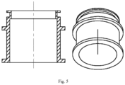
Fig. 5 shows a schematic diagram of the winding ferrule. - In the picture: Feeding conveyor belt 1, claw-pole part to be measured 2,
manipulator 3, claw-pole handling device 4,control unit 5, DC magneticperformance measuring instrument 6, out-leading of measuring coil and magnetizing winding 7, measuring unit for the overall magnetic properties of claw-poles 8, magnetic isolation pad 8-1, support base with central circular boss 8-2, magnetizing winding8-3, conducting ring 8-4, measuring coil 8-5, annular sleeve 8-6, magnetic conducting pad8-7, winding ferrule 8-8, positioning axis 8-9, hydraulic cylinder and driver8-10, claw-pole part to be measured 9, output belt forunqualified products 10, qualified claw-pole 11,Discharge conveyor belt 12. -
Fig. 1 presents the online automatic measuring system of the magnetic properties for claw-pole described in this embodiment, which includes feeding conveyor belt 1 as feeding part,manipulator 3 with overturning function, claw-pole handling device 4,control unit 5, measuring unit for the overall magnetic properties of claw-poles 8, unqualifiedproducts output belt 10 and dischargingconveyor belt 12 as discharging part. The manipulator receives the operation instructions from the control unit to grab the claw-poles to be measured on the feeding part and move them out of the measuring unit in turn. The measuring unit for the overall magnetic properties of claw-poles outputs control power to the measuring unit, receives the induced current of the claw-pole to be measured and outputs the test results to the control unit according to the instructions from the control unit. - As shown in
Fig. 2 , the measuring unit for the overall magnetic properties of claw-poles 8 includes a support base 8-2 with a central circular boss, magnetizing winding 8-3 and measuring coil 8-5 arranged on the winding ferrule 8-8 and connected with the DC magneticperformance measurement instrument 6, conducting ring 8-4 set outside the claw-pole to be measured 9, and claw-pole handling device. - As shown in
Fig. 3 , the total height of the conducting ring 8-4 is 1.1~1.2 times that of the claw-pole part to be measured. The difference between the inner diameter of conducting ring 8-4 D 0 and the outer diameter of the claw-pole part is 0.4-0.8mm, and the outer diameter of the conducting ring 8-4 is
- The conducting ring 8-4 is provided with a step structure in the bottom for matching with the support base. The conducting ring is made of a ferromagnetic material with high permeability and high saturation magnetic induction intensity. The function of the conducting ring 8-4 is mainly to form a magnetic field loop with the claw-pole to be measured.
- The outer diameter of the claw-pole to be measured in this implementation is 98.7mm, so the inner diameter of the conducting ring is 98.7 + 0.3 × 2 = 99.3mm, and the outer diameter is 99.3 + 15 × 2 = 129.3mm.
- As shown in
Fig. 4 , the diameter of the intermediate through hole in the support base 8-2 matches the diameter of the central hole of the claw-pole part. The diameter of the central boss is 3~5mm larger than that of the claw-pole boss. The thickness t 1 of the outer ring matches the thickness of the conducting ring, and the thickness t 2 of the bottom is more than 1.5 times that of the outer ring. The support base is connected with the bottom magnetic isolation pad with bolts. The support base is made of ferromagnetic material with high permeability and saturated magnetic induction intensity. - The taper of the magnetic conducting pad 8-7 is 8°.
- The winding ferrule 8-8 is provided with upper and lower spaces. The smaller upper space is used for winding measuring coil s, and the larger lower space is used for winding magnetizing windings. The inner diameter of the winding ferrule in the lower end is in clearance fit with the outer diameter of the center boss of the support base, and the winding ferrule is made of paramagnetic material.
- The winding method of the coil on the winding ferrule 8-8 is as follows. The copper wire is uniformly wound onto the lower space in the same direction to work as the magnetizing winding, and wire is wound on the upper space as the measuring coil.
- The turns number of the magnetizing winding 8-3 is 1.1~1.2 times as many as the winding turns number of the magnetizing winding needed for the claw-pole to be measured in the actual use of the motor. The maximum turns number of the corresponding measuring coil 8-5 is

- The test steps of the device are as follows:
During testing, the relevant parameters in DC magneticperformance measuring instrument 6 are set according to the type of the claw-pole to be tested, including effective cross-section area 1900mm2, magnetizing winding turns 400 turns and measuring coil turns 2 turns. The claw-pole 2 to be measured is placed in the positioning groove for claw-pole of the feeding conveyor belt 1. The driver of hydraulic cylinder 4 of the claw-pole handling device is reset. The classification scheme of measurement results is set up incontrol unit 5. Themanipulator 3 with overturning function is reset to the initial position far from the magnetic performance measuring device, and then the whole system is opened to start operation. - Step 1: The
manipulator 3 with overturning function clamps the claw-pole 2 to be measured from the predetermined position of the feeding conveyor belt 1 and puts it into the measuring unit for the overall magnetic properties of claw-poles 8 with ejection mechanism. Themanipulator 3 with overturning function resets to the initial position and transmits the signal to thecontrol unit 5. Meanwhile, the feeding conveyor belt sends the next claw-pole to the predetermined position. - Step 2: The
control unit 5 receives the signal from themanipulator 3 with overturning function and opens the DC magneticperformance measuring instrument 6. The claw-poles to be measured are demagnetized and measured in DC magneticperformance measuring instrument 6 in turn. Up to the end of the measurement, the DC magneticperformance measuring instrument 6 transmits the measurement results to thecontrol unit 5. - Step 3: The
control unit 5 receives the measurement results and sends signals to themanipulator 3 with overturning function and hydraulic cylinder driver 4 of ejection mechanism according to the classification scheme set by the system. - Step 4: The driver 4 of the claw-pole handling device receives the signal from the control unit, drives the hydraulic cylinder and ejects the measured claw-pole.
- Step 5: The
control unit 5 receives the feedback signal from driver 4, and controls themanipulator 3 to clamp the measured claw-poles to the predetermined position of the dischargingconveyor belt 12 or directly put them into theconveyor belt 10 for unqualified products. Then themanipulator 3 is reset, and the qualified products are delivered by the discharging conveyor belt to the next production process. The measurement results are shown in Table 1. - After the whole system is opened, the above-mentioned cyclic action is carried out to realize the online automatic measurement of the overall magnetic properties for claw-pole. The measuring time of each part can be adjusted by adjusting the measuring points of the DC magnetic performance measuring instrument, which is convenient for adapting to the production rhythm of the production line. By changing the classification scheme of the measurement results in the control unit, the function of screening according to the magnetic properties of the claw-poles can be realized.
Table 1 Measurement results of magnetic properties of claw-poles Serial number Average magnetic induction intensity (3.75A) Qualified or not 1 1.894 Unqualified 2 1.901 Qualified 3 1.905 Qualified 4 1.902 Qualified 5 1.900 Qualified
Claims (10)
- An online automatic detection system for the overall magnetic properties of claw-poles comprising: a feeding part, a measuring unit for the overall magnetic properties of claw-poles (8), a discharging part and a manipulator (3) arranged therein, in which the manipulator (2) receives the operation instructions from the control unit to grab the measured claw-poles (2, 9) on the feeding part and move them out of the measuring unit in turn, and the measuring unit for the overall magnetic properties of claw-poles (8) outputs control power to the measuring unit, receives the induced current of the measured claw-pole (2, 9) and outputs the test results to the control unit according to the instructions from the control unit; ferrule and a claw-pole handling device (4) arranged on the support base from inside to outside and a DC magnetic performance measurement instrument (6), in which the measured claw-pole (2, 9) is positioned and detached from the support base through the handling device (4), and the winding ferrule (8-8) is provided with measuring coils (8-5) and magnetizing windings connected with the DC magnetic performance measurement instrument (6), and the measuring coil (8-5) is located inside the measured claw-pole (2, 9);
and a conducting ring (8-4) is set outside the measured claw-pole (2, 9) to form a magnetic field loop with the measured claw-pole (2,9), and the DC magnetic performance measuring instrument (6) outputs control power to the measuring unit for the overall magnetic properties of claw-poles (8) according to the instructions of the control unit, and the magnetizing winding receives the excitation voltage from the DC magnetic performance measuring instrument (6), and the measuring coil (8-5) generates and transmits the induced current to the DC magnetic performance measuring instrument (6), and the output excitation current is recorded by the DC magnetic performance measuring instrument (6), and the detected induction current is converted to the induction voltage, and the magnetic induction intensity is calculated through integrating the voltage in the time domain, and then, the whole magnetization curve of the claw-pole part to be measured (2,9) is obtained to characterize the magnetic conductivity of the claw-pole part. - The online automatic detection system described in claim 1, it is characterized by the claw-pole handling device comprising a positioning axis (8-9) set inside the support base and a hydraulic cylinder (8-10) connected with the positioning axis (8-9), and a magnetic conducting pad (8-7) is arranged on the positioning axis (8-9), which is located between the support base (8-2) and the measured claw-pole (2, 9), and the positioning and detachment of the measured claw-pole and the support base are realized by driving the lifting of the positioning axis (8-9) through the hydraulic cylinder (8-10).
- The online automatic detection system described in claim 1, in which the said positioning axis (8-9) is a ladder-shaped structure for ensuring the coaxiality between the measured claw-pole and the central boss of the support base, and the joint surface of the large end and the small end of the positioning axis contacts the lower end surface of the ring magnetic conducting pad (8-7), and the diameter of the large end matches the inner diameter of the central hole of the measured claw-pole (2,9) , and the diameter of the small end matches the inner diameter of the ring magnetic conducting pad (8-7).
- The online automatic detection system described in claim 1, in which the said outer diameter of the magnetic conducting pad (8-7) is smaller than that of the center boss of the support base (8-2) and the inner diameter is smaller than that of the inner hole of the measured claw-pole (2,9).
- The online automatic detection system described in any of claim 2-4, in which the said magnetic conducting pad (8-7) has a taper to facilitate assembly and disassembly.
- The online automatic detection system described in claim 1, in which an annular sleeve is arranged on the contact surface between the positioning axis (8-9) and the measured claw-pole (2,9) , and the inner diameter of the annular sleeve matches the outer diameter of the small end of the positioning axis and the outer diameter matches the inner diameter of the central hole of the measured claw-pole.
- The online automatic detection system described in claim 1, in which the said winding ferrule (8-8) is provided with upper and lower spaces, and the smaller upper space is used for winding measuring coils, and the larger lower space is used for winding magnetizing windings, and the inner diameter of the winding ferrule (8-8) in the lower end is in clearance fit with the outer diameter of the center boss of the support base (8-2).
- The online automatic detection system described in claim 1, in which the said magnetic field is generated through electromagnetic induction when the magnetizing winding is fed into the excitation current I, and the corresponding external magnetic field strength is H = N1 × I / Le, where N1 is the number of turns of the magnetizing winding, Le is the equivalent magnetic circuit length. After measuring the induced electrical signal generated in the exitation coil, the induction current is calculated by the electronic integrator, and then the induction magnetic flux Φ induced in the coil is calculated; as the external magnetic field strength increases, the corresponding magnetic induction intensity is calculated to be B = Φ / (N2× Ae ), where N2 is the number of turns of magnetizing winding, Ae is the equivalent cross-section area.
- The online automatic detection system described in claim 1, in which the said discharging part includes two conveyor belts (1) for carrying qualified claw-poles and unqualified claw-poles respectively, and the conveyor belt (1) with qualified claw-poles coincides with the starting end of the conveyor belt with defective claw-poles.
- The online automatic detection system described in claim 1, in which the said manipulator (3) have a overturning function, and the manipulator clamps the claw-pole to be measured (2, 9) from the feeding conveyor belt (1) into the measuring device of the magnetic performance for the claw-pole in turn by receiving the instructions from the control unit, and waits for the signal from the control unit to clamp the tested claw-pole to the discharging conveyor belt;
and the control unit comprises the central controller, the manipulator controller and driver, the conveyor belt controller and driver, the claw-pole handling controller and driver, and the central controller is respectively connected with the manipulator controller, the DC magnetic performance measuring instrument, the conveyor belt controller and the claw-pole handling controller and sends out control signals to them, and the DC magnetic performance measuring instrument transmits the measurement results to the central controller to achieve orderly detection and classification.
Applications Claiming Priority (2)
| Application Number | Priority Date | Filing Date | Title |
|---|---|---|---|
| CN201810768917.4A CN108889641B (en) | 2018-07-13 | 2018-07-13 | On-line automatic measurement system for overall magnetic properties of claw poles |
| PCT/CN2019/094315 WO2020011060A1 (en) | 2018-07-13 | 2019-07-02 | Online automation measurement system for claw-pole overall magnetic property |
Publications (3)
| Publication Number | Publication Date |
|---|---|
| EP3821989A1 EP3821989A1 (en) | 2021-05-19 |
| EP3821989A4 EP3821989A4 (en) | 2022-03-23 |
| EP3821989B1 true EP3821989B1 (en) | 2024-01-03 |
Family
ID=64349543
Family Applications (1)
| Application Number | Title | Priority Date | Filing Date |
|---|---|---|---|
| EP19833721.4A Active EP3821989B1 (en) | 2018-07-13 | 2019-07-02 | Online automation measurement system for claw-pole overall magnetic property |
Country Status (5)
| Country | Link |
|---|---|
| US (1) | US11366185B2 (en) |
| EP (1) | EP3821989B1 (en) |
| JP (1) | JP6933833B2 (en) |
| CN (1) | CN108889641B (en) |
| WO (1) | WO2020011060A1 (en) |
Families Citing this family (6)
| Publication number | Priority date | Publication date | Assignee | Title |
|---|---|---|---|---|
| CN109116232B (en) * | 2018-07-13 | 2019-08-02 | 上海交通大学 | Magnetic property measuring device towards seriation claw-pole type generator rotor |
| CN108889641B (en) * | 2018-07-13 | 2019-04-23 | 江苏龙城精锻有限公司 | On-line automatic measurement system for overall magnetic properties of claw poles |
| CN115940525A (en) * | 2021-09-07 | 2023-04-07 | 博山特型电机有限公司 | A kind of manufacturing method of motor and motor rotor thereof |
| CN114472220B (en) * | 2021-12-21 | 2024-06-25 | 江苏永炬锻造有限公司 | Intelligent detection equipment for clamping die forging fork-shaped piece and application method thereof |
| CN114397610A (en) * | 2021-12-31 | 2022-04-26 | 江苏龙城精锻集团有限公司 | Combined automobile claw-pole type generator claw-pole magnetic performance measuring device and method |
| CN117299621B (en) * | 2023-10-25 | 2026-05-01 | 张家港保税区长隆新材料有限公司 | Turnover type blanking mechanism of floor film inspection machine and floor film inspection and acceptance equipment |
Family Cites Families (19)
| Publication number | Priority date | Publication date | Assignee | Title |
|---|---|---|---|---|
| US3481185A (en) * | 1967-07-14 | 1969-12-02 | Ibm | Core testing |
| DE1913680A1 (en) * | 1969-03-18 | 1970-10-01 | Siemens Ag | Device for measuring electrical components, in particular toroidal cores made of ferromagnetic material, and for sorting the measured electrical components |
| JPS5129987A (en) * | 1974-09-04 | 1976-03-13 | Eishin Kagaku Kk | JIKITAN SHOHOHO |
| JPS61180163A (en) * | 1985-01-09 | 1986-08-12 | Hitachi Electronics Eng Co Ltd | Inspection system for floppy recording medium |
| US4801877A (en) * | 1986-05-06 | 1989-01-31 | General Electric Company | Method and apparatus for testing dynamoelectric machine rotors |
| JPH04295788A (en) * | 1991-03-25 | 1992-10-20 | Toshiba Corp | Magnetic sensor |
| KR970009203B1 (en) * | 1993-12-29 | 1997-06-07 | Lg Metal Co Ltd | Permanent magnet testing & selecting apparatus |
| JP3580905B2 (en) * | 1995-06-13 | 2004-10-27 | 大日本印刷株式会社 | Magnetic sensor |
| JP3501016B2 (en) * | 1999-06-10 | 2004-02-23 | Jfeスチール株式会社 | Apparatus and method for measuring dynamic magnetic characteristics of motor stator core |
| JP4267519B2 (en) * | 2004-05-14 | 2009-05-27 | 新日本製鐵株式会社 | Stator core manufacturing method and electric device manufacturing method using the same |
| DE102005021496A1 (en) * | 2005-05-10 | 2006-11-16 | Robert Bosch Gmbh | Method for producing a magnetically active element of an electrical machine and device for carrying out the method |
| JP2011097730A (en) * | 2009-10-29 | 2011-05-12 | Daihatsu Motor Co Ltd | Motor |
| WO2012061970A1 (en) * | 2010-11-08 | 2012-05-18 | Abb Technology Ab | Batteries testing and sorting system and the method thereof |
| CN104515959A (en) * | 2014-12-25 | 2015-04-15 | 浙江融创磁业有限公司 | Equipment and method for automatically detecting magnetic flux of special magnetic steel for electronic power motor of steering wheel of automobile |
| JP6509568B2 (en) * | 2015-01-19 | 2019-05-08 | 株式会社Soken | Rotation angle detection device |
| CN104889078B (en) * | 2015-05-27 | 2018-11-27 | 黄艳红 | A kind of on-line automatic sorting unit of ring inductance |
| CN104898059B (en) * | 2015-05-29 | 2017-09-26 | 中山明杰自动化科技有限公司 | Permanent-magnet claw-pole stepping motor function test full-detection machine |
| CN206002667U (en) * | 2016-08-29 | 2017-03-08 | 广东利迅达机器人系统股份有限公司 | A kind of motor positive and inverse automatic testing equipment |
| CN108889641B (en) * | 2018-07-13 | 2019-04-23 | 江苏龙城精锻有限公司 | On-line automatic measurement system for overall magnetic properties of claw poles |
-
2018
- 2018-07-13 CN CN201810768917.4A patent/CN108889641B/en active Active
-
2019
- 2019-07-02 WO PCT/CN2019/094315 patent/WO2020011060A1/en not_active Ceased
- 2019-07-02 US US16/645,879 patent/US11366185B2/en active Active
- 2019-07-02 EP EP19833721.4A patent/EP3821989B1/en active Active
- 2019-07-02 JP JP2020542494A patent/JP6933833B2/en active Active
Also Published As
| Publication number | Publication date |
|---|---|
| EP3821989A1 (en) | 2021-05-19 |
| US11366185B2 (en) | 2022-06-21 |
| EP3821989A4 (en) | 2022-03-23 |
| JP2020537167A (en) | 2020-12-17 |
| CN108889641B (en) | 2019-04-23 |
| WO2020011060A1 (en) | 2020-01-16 |
| US20200284858A1 (en) | 2020-09-10 |
| JP6933833B2 (en) | 2021-09-08 |
| CN108889641A (en) | 2018-11-27 |
Similar Documents
| Publication | Publication Date | Title |
|---|---|---|
| EP3821989A1 (en) | Online automation measurement system for claw-pole overall magnetic property | |
| CN112802653B (en) | Magnetizing and demagnetizing method, magnetizing and demagnetizing magnetic head and magnetizing and demagnetizing machine | |
| CN102854241B (en) | Be suitable for the axial magnetized device of steel pipe short dead zone transverse defect high speed detection | |
| CN105116266B (en) | A kind of band center pillar core inductance automatic sorting instrument | |
| CN207704011U (en) | A kind of magnetic element weight and magnetic flux detection device | |
| CN108311419B (en) | Integrated circuit test sorting machine | |
| CN103698392B (en) | Pulling rivet group magnetic group method of detection and device | |
| CN212460013U (en) | Amorphous alloy annular sample magnetic property measurement sample table | |
| EP2902779A1 (en) | System for measuring the properties of soft magnetic materials, in particular sheets and bands | |
| CN103207233A (en) | Magnetizer of large gear ring workpiece magnetic particle flaw detector | |
| CN118341701A (en) | Inductor core detection device and detection method | |
| CN203133025U (en) | Large ring unit magnetic powder inspection magnetization device | |
| CN203630088U (en) | Rivet group magnetization flaw detection device | |
| CN203148895U (en) | Magnetizing device of magnetic particle flaw detector for big gear ring workpieces | |
| CN2222352Y (en) | Probe of high-resolution single-probe internal stress magnetometer | |
| CN105405626A (en) | Current transformer of high-power and medium-high frequency power supply and winding method | |
| KR101726067B1 (en) | Magnetic particle testing apparatus | |
| RU2828161C1 (en) | Installation for magnetic particle flaw detection of bearing rings | |
| CN104597119B (en) | A kind of out star wheel magnetic spy machine | |
| RU2419905C1 (en) | Demagnetisation method of thin-wall annular parts of large diametre from ferromagnetic steels | |
| JP6753292B2 (en) | How to manufacture the rotor | |
| CN106597120A (en) | Magnetic core test platform | |
| JPS61253475A (en) | Automatic tester for zinc oxide arrestor | |
| JP3269225B2 (en) | Print coil tester | |
| CN119314775A (en) | A four-station Halbach multi-pole magnetic ring charging and testing machine |
Legal Events
| Date | Code | Title | Description |
|---|---|---|---|
| STAA | Information on the status of an ep patent application or granted ep patent |
Free format text: STATUS: THE INTERNATIONAL PUBLICATION HAS BEEN MADE |
|
| PUAI | Public reference made under article 153(3) epc to a published international application that has entered the european phase |
Free format text: ORIGINAL CODE: 0009012 |
|
| STAA | Information on the status of an ep patent application or granted ep patent |
Free format text: STATUS: REQUEST FOR EXAMINATION WAS MADE |
|
| 17P | Request for examination filed |
Effective date: 20200619 |
|
| AK | Designated contracting states |
Kind code of ref document: A1 Designated state(s): AL AT BE BG CH CY CZ DE DK EE ES FI FR GB GR HR HU IE IS IT LI LT LU LV MC MK MT NL NO PL PT RO RS SE SI SK SM TR |
|
| DAV | Request for validation of the european patent (deleted) | ||
| DAX | Request for extension of the european patent (deleted) | ||
| A4 | Supplementary search report drawn up and despatched |
Effective date: 20220218 |
|
| RIC1 | Information provided on ipc code assigned before grant |
Ipc: G01R 33/12 20060101ALI20220215BHEP Ipc: B07C 5/344 20060101AFI20220215BHEP |
|
| GRAP | Despatch of communication of intention to grant a patent |
Free format text: ORIGINAL CODE: EPIDOSNIGR1 |
|
| STAA | Information on the status of an ep patent application or granted ep patent |
Free format text: STATUS: GRANT OF PATENT IS INTENDED |
|
| INTG | Intention to grant announced |
Effective date: 20230719 |
|
| GRAS | Grant fee paid |
Free format text: ORIGINAL CODE: EPIDOSNIGR3 |
|
| GRAA | (expected) grant |
Free format text: ORIGINAL CODE: 0009210 |
|
| STAA | Information on the status of an ep patent application or granted ep patent |
Free format text: STATUS: THE PATENT HAS BEEN GRANTED |
|
| AK | Designated contracting states |
Kind code of ref document: B1 Designated state(s): AL AT BE BG CH CY CZ DE DK EE ES FI FR GB GR HR HU IE IS IT LI LT LU LV MC MK MT NL NO PL PT RO RS SE SI SK SM TR |
|
| REG | Reference to a national code |
Ref country code: GB Ref legal event code: FG4D |
|
| REG | Reference to a national code |
Ref country code: DE Ref legal event code: R096 Ref document number: 602019044604 Country of ref document: DE |
|
| REG | Reference to a national code |
Ref country code: CH Ref legal event code: EP |
|
| REG | Reference to a national code |
Ref country code: IE Ref legal event code: FG4D |
|
| REG | Reference to a national code |
Ref country code: LT Ref legal event code: MG9D |
|
| PG25 | Lapsed in a contracting state [announced via postgrant information from national office to epo] |
Ref country code: ES Free format text: LAPSE BECAUSE OF FAILURE TO SUBMIT A TRANSLATION OF THE DESCRIPTION OR TO PAY THE FEE WITHIN THE PRESCRIBED TIME-LIMIT Effective date: 20240103 |
|
| PG25 | Lapsed in a contracting state [announced via postgrant information from national office to epo] |
Ref country code: ES Free format text: LAPSE BECAUSE OF FAILURE TO SUBMIT A TRANSLATION OF THE DESCRIPTION OR TO PAY THE FEE WITHIN THE PRESCRIBED TIME-LIMIT Effective date: 20240103 |
|
| REG | Reference to a national code |
Ref country code: NL Ref legal event code: MP Effective date: 20240103 |
|
| REG | Reference to a national code |
Ref country code: AT Ref legal event code: MK05 Ref document number: 1646282 Country of ref document: AT Kind code of ref document: T Effective date: 20240103 |
|
| PG25 | Lapsed in a contracting state [announced via postgrant information from national office to epo] |
Ref country code: NL Free format text: LAPSE BECAUSE OF FAILURE TO SUBMIT A TRANSLATION OF THE DESCRIPTION OR TO PAY THE FEE WITHIN THE PRESCRIBED TIME-LIMIT Effective date: 20240103 |
|
| PG25 | Lapsed in a contracting state [announced via postgrant information from national office to epo] |
Ref country code: NL Free format text: LAPSE BECAUSE OF FAILURE TO SUBMIT A TRANSLATION OF THE DESCRIPTION OR TO PAY THE FEE WITHIN THE PRESCRIBED TIME-LIMIT Effective date: 20240103 |
|
| PG25 | Lapsed in a contracting state [announced via postgrant information from national office to epo] |
Ref country code: IS Free format text: LAPSE BECAUSE OF FAILURE TO SUBMIT A TRANSLATION OF THE DESCRIPTION OR TO PAY THE FEE WITHIN THE PRESCRIBED TIME-LIMIT Effective date: 20240503 |
|
| PG25 | Lapsed in a contracting state [announced via postgrant information from national office to epo] |
Ref country code: LT Free format text: LAPSE BECAUSE OF FAILURE TO SUBMIT A TRANSLATION OF THE DESCRIPTION OR TO PAY THE FEE WITHIN THE PRESCRIBED TIME-LIMIT Effective date: 20240103 |
|
| PG25 | Lapsed in a contracting state [announced via postgrant information from national office to epo] |
Ref country code: GR Free format text: LAPSE BECAUSE OF FAILURE TO SUBMIT A TRANSLATION OF THE DESCRIPTION OR TO PAY THE FEE WITHIN THE PRESCRIBED TIME-LIMIT Effective date: 20240404 |
|
| PG25 | Lapsed in a contracting state [announced via postgrant information from national office to epo] |
Ref country code: RS Free format text: LAPSE BECAUSE OF FAILURE TO SUBMIT A TRANSLATION OF THE DESCRIPTION OR TO PAY THE FEE WITHIN THE PRESCRIBED TIME-LIMIT Effective date: 20240403 Ref country code: HR Free format text: LAPSE BECAUSE OF FAILURE TO SUBMIT A TRANSLATION OF THE DESCRIPTION OR TO PAY THE FEE WITHIN THE PRESCRIBED TIME-LIMIT Effective date: 20240103 |
|
| PG25 | Lapsed in a contracting state [announced via postgrant information from national office to epo] |
Ref country code: CZ Free format text: LAPSE BECAUSE OF FAILURE TO SUBMIT A TRANSLATION OF THE DESCRIPTION OR TO PAY THE FEE WITHIN THE PRESCRIBED TIME-LIMIT Effective date: 20240103 Ref country code: AT Free format text: LAPSE BECAUSE OF FAILURE TO SUBMIT A TRANSLATION OF THE DESCRIPTION OR TO PAY THE FEE WITHIN THE PRESCRIBED TIME-LIMIT Effective date: 20240103 |
|
| PG25 | Lapsed in a contracting state [announced via postgrant information from national office to epo] |
Ref country code: RS Free format text: LAPSE BECAUSE OF FAILURE TO SUBMIT A TRANSLATION OF THE DESCRIPTION OR TO PAY THE FEE WITHIN THE PRESCRIBED TIME-LIMIT Effective date: 20240403 Ref country code: NO Free format text: LAPSE BECAUSE OF FAILURE TO SUBMIT A TRANSLATION OF THE DESCRIPTION OR TO PAY THE FEE WITHIN THE PRESCRIBED TIME-LIMIT Effective date: 20240403 Ref country code: LT Free format text: LAPSE BECAUSE OF FAILURE TO SUBMIT A TRANSLATION OF THE DESCRIPTION OR TO PAY THE FEE WITHIN THE PRESCRIBED TIME-LIMIT Effective date: 20240103 Ref country code: IS Free format text: LAPSE BECAUSE OF FAILURE TO SUBMIT A TRANSLATION OF THE DESCRIPTION OR TO PAY THE FEE WITHIN THE PRESCRIBED TIME-LIMIT Effective date: 20240503 Ref country code: HR Free format text: LAPSE BECAUSE OF FAILURE TO SUBMIT A TRANSLATION OF THE DESCRIPTION OR TO PAY THE FEE WITHIN THE PRESCRIBED TIME-LIMIT Effective date: 20240103 Ref country code: GR Free format text: LAPSE BECAUSE OF FAILURE TO SUBMIT A TRANSLATION OF THE DESCRIPTION OR TO PAY THE FEE WITHIN THE PRESCRIBED TIME-LIMIT Effective date: 20240404 Ref country code: CZ Free format text: LAPSE BECAUSE OF FAILURE TO SUBMIT A TRANSLATION OF THE DESCRIPTION OR TO PAY THE FEE WITHIN THE PRESCRIBED TIME-LIMIT Effective date: 20240103 Ref country code: BG Free format text: LAPSE BECAUSE OF FAILURE TO SUBMIT A TRANSLATION OF THE DESCRIPTION OR TO PAY THE FEE WITHIN THE PRESCRIBED TIME-LIMIT Effective date: 20240103 Ref country code: AT Free format text: LAPSE BECAUSE OF FAILURE TO SUBMIT A TRANSLATION OF THE DESCRIPTION OR TO PAY THE FEE WITHIN THE PRESCRIBED TIME-LIMIT Effective date: 20240103 |
|
| PG25 | Lapsed in a contracting state [announced via postgrant information from national office to epo] |
Ref country code: PT Free format text: LAPSE BECAUSE OF FAILURE TO SUBMIT A TRANSLATION OF THE DESCRIPTION OR TO PAY THE FEE WITHIN THE PRESCRIBED TIME-LIMIT Effective date: 20240503 Ref country code: PL Free format text: LAPSE BECAUSE OF FAILURE TO SUBMIT A TRANSLATION OF THE DESCRIPTION OR TO PAY THE FEE WITHIN THE PRESCRIBED TIME-LIMIT Effective date: 20240103 |
|
| PG25 | Lapsed in a contracting state [announced via postgrant information from national office to epo] |
Ref country code: SE Free format text: LAPSE BECAUSE OF FAILURE TO SUBMIT A TRANSLATION OF THE DESCRIPTION OR TO PAY THE FEE WITHIN THE PRESCRIBED TIME-LIMIT Effective date: 20240103 Ref country code: PT Free format text: LAPSE BECAUSE OF FAILURE TO SUBMIT A TRANSLATION OF THE DESCRIPTION OR TO PAY THE FEE WITHIN THE PRESCRIBED TIME-LIMIT Effective date: 20240503 Ref country code: PL Free format text: LAPSE BECAUSE OF FAILURE TO SUBMIT A TRANSLATION OF THE DESCRIPTION OR TO PAY THE FEE WITHIN THE PRESCRIBED TIME-LIMIT Effective date: 20240103 Ref country code: LV Free format text: LAPSE BECAUSE OF FAILURE TO SUBMIT A TRANSLATION OF THE DESCRIPTION OR TO PAY THE FEE WITHIN THE PRESCRIBED TIME-LIMIT Effective date: 20240103 |
|
| REG | Reference to a national code |
Ref country code: DE Ref legal event code: R097 Ref document number: 602019044604 Country of ref document: DE |
|
| PG25 | Lapsed in a contracting state [announced via postgrant information from national office to epo] |
Ref country code: DK Free format text: LAPSE BECAUSE OF FAILURE TO SUBMIT A TRANSLATION OF THE DESCRIPTION OR TO PAY THE FEE WITHIN THE PRESCRIBED TIME-LIMIT Effective date: 20240103 |
|
| PG25 | Lapsed in a contracting state [announced via postgrant information from national office to epo] |
Ref country code: SM Free format text: LAPSE BECAUSE OF FAILURE TO SUBMIT A TRANSLATION OF THE DESCRIPTION OR TO PAY THE FEE WITHIN THE PRESCRIBED TIME-LIMIT Effective date: 20240103 |
|
| PG25 | Lapsed in a contracting state [announced via postgrant information from national office to epo] |
Ref country code: EE Free format text: LAPSE BECAUSE OF FAILURE TO SUBMIT A TRANSLATION OF THE DESCRIPTION OR TO PAY THE FEE WITHIN THE PRESCRIBED TIME-LIMIT Effective date: 20240103 |
|
| PG25 | Lapsed in a contracting state [announced via postgrant information from national office to epo] |
Ref country code: SK Free format text: LAPSE BECAUSE OF FAILURE TO SUBMIT A TRANSLATION OF THE DESCRIPTION OR TO PAY THE FEE WITHIN THE PRESCRIBED TIME-LIMIT Effective date: 20240103 |
|
| PG25 | Lapsed in a contracting state [announced via postgrant information from national office to epo] |
Ref country code: SM Free format text: LAPSE BECAUSE OF FAILURE TO SUBMIT A TRANSLATION OF THE DESCRIPTION OR TO PAY THE FEE WITHIN THE PRESCRIBED TIME-LIMIT Effective date: 20240103 Ref country code: SK Free format text: LAPSE BECAUSE OF FAILURE TO SUBMIT A TRANSLATION OF THE DESCRIPTION OR TO PAY THE FEE WITHIN THE PRESCRIBED TIME-LIMIT Effective date: 20240103 Ref country code: RO Free format text: LAPSE BECAUSE OF FAILURE TO SUBMIT A TRANSLATION OF THE DESCRIPTION OR TO PAY THE FEE WITHIN THE PRESCRIBED TIME-LIMIT Effective date: 20240103 Ref country code: EE Free format text: LAPSE BECAUSE OF FAILURE TO SUBMIT A TRANSLATION OF THE DESCRIPTION OR TO PAY THE FEE WITHIN THE PRESCRIBED TIME-LIMIT Effective date: 20240103 Ref country code: DK Free format text: LAPSE BECAUSE OF FAILURE TO SUBMIT A TRANSLATION OF THE DESCRIPTION OR TO PAY THE FEE WITHIN THE PRESCRIBED TIME-LIMIT Effective date: 20240103 |
|
| PLBE | No opposition filed within time limit |
Free format text: ORIGINAL CODE: 0009261 |
|
| STAA | Information on the status of an ep patent application or granted ep patent |
Free format text: STATUS: NO OPPOSITION FILED WITHIN TIME LIMIT |
|
| PG25 | Lapsed in a contracting state [announced via postgrant information from national office to epo] |
Ref country code: IT Free format text: LAPSE BECAUSE OF FAILURE TO SUBMIT A TRANSLATION OF THE DESCRIPTION OR TO PAY THE FEE WITHIN THE PRESCRIBED TIME-LIMIT Effective date: 20240103 |
|
| 26N | No opposition filed |
Effective date: 20241007 |
|
| PG25 | Lapsed in a contracting state [announced via postgrant information from national office to epo] |
Ref country code: IT Free format text: LAPSE BECAUSE OF FAILURE TO SUBMIT A TRANSLATION OF THE DESCRIPTION OR TO PAY THE FEE WITHIN THE PRESCRIBED TIME-LIMIT Effective date: 20240103 |
|
| PG25 | Lapsed in a contracting state [announced via postgrant information from national office to epo] |
Ref country code: MC Free format text: LAPSE BECAUSE OF FAILURE TO SUBMIT A TRANSLATION OF THE DESCRIPTION OR TO PAY THE FEE WITHIN THE PRESCRIBED TIME-LIMIT Effective date: 20240103 |
|
| REG | Reference to a national code |
Ref country code: CH Ref legal event code: PL |
|
| PG25 | Lapsed in a contracting state [announced via postgrant information from national office to epo] |
Ref country code: LU Free format text: LAPSE BECAUSE OF NON-PAYMENT OF DUE FEES Effective date: 20240702 |
|
| PG25 | Lapsed in a contracting state [announced via postgrant information from national office to epo] |
Ref country code: LU Free format text: LAPSE BECAUSE OF NON-PAYMENT OF DUE FEES Effective date: 20240702 |
|
| PG25 | Lapsed in a contracting state [announced via postgrant information from national office to epo] |
Ref country code: CH Free format text: LAPSE BECAUSE OF NON-PAYMENT OF DUE FEES Effective date: 20240731 Ref country code: SI Free format text: LAPSE BECAUSE OF FAILURE TO SUBMIT A TRANSLATION OF THE DESCRIPTION OR TO PAY THE FEE WITHIN THE PRESCRIBED TIME-LIMIT Effective date: 20240103 Ref country code: BE Free format text: LAPSE BECAUSE OF NON-PAYMENT OF DUE FEES Effective date: 20240731 |
|
| REG | Reference to a national code |
Ref country code: BE Ref legal event code: MM Effective date: 20240731 |
|
| PG25 | Lapsed in a contracting state [announced via postgrant information from national office to epo] |
Ref country code: IE Free format text: LAPSE BECAUSE OF NON-PAYMENT OF DUE FEES Effective date: 20240702 |
|
| PG25 | Lapsed in a contracting state [announced via postgrant information from national office to epo] |
Ref country code: FI Free format text: LAPSE BECAUSE OF FAILURE TO SUBMIT A TRANSLATION OF THE DESCRIPTION OR TO PAY THE FEE WITHIN THE PRESCRIBED TIME-LIMIT Effective date: 20240103 |
|
| PGFP | Annual fee paid to national office [announced via postgrant information from national office to epo] |
Ref country code: DE Payment date: 20250729 Year of fee payment: 7 |
|
| PGFP | Annual fee paid to national office [announced via postgrant information from national office to epo] |
Ref country code: GB Payment date: 20250729 Year of fee payment: 7 |
|
| PGFP | Annual fee paid to national office [announced via postgrant information from national office to epo] |
Ref country code: FR Payment date: 20250729 Year of fee payment: 7 |
|
| PG25 | Lapsed in a contracting state [announced via postgrant information from national office to epo] |
Ref country code: CY Free format text: LAPSE BECAUSE OF FAILURE TO SUBMIT A TRANSLATION OF THE DESCRIPTION OR TO PAY THE FEE WITHIN THE PRESCRIBED TIME-LIMIT; INVALID AB INITIO Effective date: 20190702 |
|
| PG25 | Lapsed in a contracting state [announced via postgrant information from national office to epo] |
Ref country code: HU Free format text: LAPSE BECAUSE OF FAILURE TO SUBMIT A TRANSLATION OF THE DESCRIPTION OR TO PAY THE FEE WITHIN THE PRESCRIBED TIME-LIMIT; INVALID AB INITIO Effective date: 20190702 |
|
| PG25 | Lapsed in a contracting state [announced via postgrant information from national office to epo] |
Ref country code: TR Free format text: LAPSE BECAUSE OF FAILURE TO SUBMIT A TRANSLATION OF THE DESCRIPTION OR TO PAY THE FEE WITHIN THE PRESCRIBED TIME-LIMIT Effective date: 20240103 |