EP3821114B1 - Entlüftungsbremse mit vorgesteuerter brücke mit hla - Google Patents
Entlüftungsbremse mit vorgesteuerter brücke mit hla Download PDFInfo
- Publication number
- EP3821114B1 EP3821114B1 EP19834097.8A EP19834097A EP3821114B1 EP 3821114 B1 EP3821114 B1 EP 3821114B1 EP 19834097 A EP19834097 A EP 19834097A EP 3821114 B1 EP3821114 B1 EP 3821114B1
- Authority
- EP
- European Patent Office
- Prior art keywords
- assembly
- valve
- engine
- bridge
- lever
- Prior art date
- Legal status (The legal status is an assumption and is not a legal conclusion. Google has not performed a legal analysis and makes no representation as to the accuracy of the status listed.)
- Active
Links
Images


Classifications
-
- F—MECHANICAL ENGINEERING; LIGHTING; HEATING; WEAPONS; BLASTING
- F01—MACHINES OR ENGINES IN GENERAL; ENGINE PLANTS IN GENERAL; STEAM ENGINES
- F01L—CYCLICALLY OPERATING VALVES FOR MACHINES OR ENGINES
- F01L1/00—Valve-gear or valve arrangements, e.g. lift-valve gear
- F01L1/12—Transmitting gear between valve drive and valve
- F01L1/18—Rocking arms or levers
- F01L1/181—Centre pivot rocking arms
-
- F—MECHANICAL ENGINEERING; LIGHTING; HEATING; WEAPONS; BLASTING
- F01—MACHINES OR ENGINES IN GENERAL; ENGINE PLANTS IN GENERAL; STEAM ENGINES
- F01L—CYCLICALLY OPERATING VALVES FOR MACHINES OR ENGINES
- F01L1/00—Valve-gear or valve arrangements, e.g. lift-valve gear
- F01L1/12—Transmitting gear between valve drive and valve
- F01L1/14—Tappets; Push rods
- F01L1/146—Push-rods
-
- F—MECHANICAL ENGINEERING; LIGHTING; HEATING; WEAPONS; BLASTING
- F01—MACHINES OR ENGINES IN GENERAL; ENGINE PLANTS IN GENERAL; STEAM ENGINES
- F01L—CYCLICALLY OPERATING VALVES FOR MACHINES OR ENGINES
- F01L1/00—Valve-gear or valve arrangements, e.g. lift-valve gear
- F01L1/20—Adjusting or compensating clearance
- F01L1/22—Adjusting or compensating clearance automatically, e.g. mechanically
- F01L1/24—Adjusting or compensating clearance automatically, e.g. mechanically by fluid means, e.g. hydraulically
-
- F—MECHANICAL ENGINEERING; LIGHTING; HEATING; WEAPONS; BLASTING
- F01—MACHINES OR ENGINES IN GENERAL; ENGINE PLANTS IN GENERAL; STEAM ENGINES
- F01L—CYCLICALLY OPERATING VALVES FOR MACHINES OR ENGINES
- F01L1/00—Valve-gear or valve arrangements, e.g. lift-valve gear
- F01L1/26—Valve-gear or valve arrangements, e.g. lift-valve gear characterised by the provision of two or more valves operated simultaneously by same transmitting-gear; peculiar to machines or engines with more than two lift-valves per cylinder
-
- F—MECHANICAL ENGINEERING; LIGHTING; HEATING; WEAPONS; BLASTING
- F01—MACHINES OR ENGINES IN GENERAL; ENGINE PLANTS IN GENERAL; STEAM ENGINES
- F01L—CYCLICALLY OPERATING VALVES FOR MACHINES OR ENGINES
- F01L13/00—Modifications of valve-gear to facilitate reversing, braking, starting, changing compression ratio, or other specific operations
- F01L13/06—Modifications of valve-gear to facilitate reversing, braking, starting, changing compression ratio, or other specific operations for braking
- F01L13/065—Compression release engine retarders of the "Jacobs Manufacturing" type
-
- F—MECHANICAL ENGINEERING; LIGHTING; HEATING; WEAPONS; BLASTING
- F01—MACHINES OR ENGINES IN GENERAL; ENGINE PLANTS IN GENERAL; STEAM ENGINES
- F01L—CYCLICALLY OPERATING VALVES FOR MACHINES OR ENGINES
- F01L1/00—Valve-gear or valve arrangements, e.g. lift-valve gear
- F01L1/20—Adjusting or compensating clearance
- F01L1/22—Adjusting or compensating clearance automatically, e.g. mechanically
- F01L1/24—Adjusting or compensating clearance automatically, e.g. mechanically by fluid means, e.g. hydraulically
- F01L2001/2427—Adjusting or compensating clearance automatically, e.g. mechanically by fluid means, e.g. hydraulically by means of an hydraulic adjusting device located between cam and push rod
Definitions
- the present disclosure generally relates to valvetrain assemblies for internal combustion engines and, more particularly, to a valvetrain assembly for bleeder braking.
- Engine braking can be used to retard forces within an engine to ultimately slow a vehicle down.
- an exhaust valve is actuated by a rocker arm which engages the exhaust valve by means of a valve bridge.
- the rocker arm rocks in response to a cam on a rotating cam shaft and presses down on the valve bridge which itself presses down on the exhaust valve to open it.
- Bleeder brakes can be used as auxiliary brakes, in addition to wheel brakes, on relatively large vehicles, for example trucks, powered by heavy or medium duty diesel engines.
- a bleeder brake typically includes a piston that selectively extends to a full stroke. In the full stroke, the piston can maintain an exhaust valve open a fixed amount throughout an engine cycle.
- a mechanical gap can be generated in the valve train. In many instances, such a gap can be incompatible with a common hydraulic lash adjuster (HLA).
- HLA hydraulic lash adjuster
- a hydraulic lash adjuster may also be provided in the valve train assembly to remove any lash or gap that develops between the components in the valve train assembly. The mechanical gap can allow the HLA to unfavorably pump- up preventing the exhaust valves to close once the bleeder brake is deactivated.
- EP 0 974 740 A2 relates to a valvetrain assembly having a rocker arm a rocker arm rotating about a rocker shaft, a camshaft having a lobe for imparting motion to the rocker arm through a pushrod, a valve bridge assembly configured to be selectively engaged by the rocker arm so as to open engine valves, and an engine brake capsule associated with the valve bridge assembly for operating in a drive mode or a brake mode.
- Similar valvetrain assemblies are known from US 2017/175597 A1 and from US 2017/276034 A1 .
- WO 2017/160379 A1 relates to valvetrain assembly which is not pushrod actuated.
- the invention relates to a valvetrain assembly as defined in claim 1 configured to selectively perform a bleeder brake operation and to a method of operating a valvetrain assembly as defined in claim 9, respectively.
- a bleeder brake which holds an exhaust valve open to generate brake power, can cause a valvetrain with an HLA to "pump-up" and prevent the exhaust valve from closing during normal drive mode operation.
- the systems described herein utilizes a fixed brake capsule with oil control to hold open one exhaust valve during engine braking operations, which is commonly referred to as a "bleeder brake.”
- the additional use of a balanced valve bridge featuring an offset pivot arm can generate a reaction load when acted upon by the fixed brake capsule. This reaction force is translated back into the normal valvetrain to facilitate preventing the HLA pump-up (e.g., expansion).
- one or more exhaust valves are held open throughout the remaining engine cycles (i.e. , the intake, compression, and expansion cycles) for a full-cycle bleeder brake or during a portion of the remaining cycles (e.g., the compression and expansion cycles) for a partial-cycle bleeder brake.
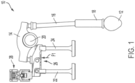
- valve train assembly 10 constructed in accordance to one example of the present disclosure is shown and generally identified at reference 10.
- the valve train assembly 10 can generally include a cam shaft 12 with one or more lobes configured to indirectly drive a first end of a rocker arm 14 via a pushrod 16.
- a hydraulic lash adjuster (HLA) lifter 18 is implemented between the cam lobe 12 and the pushrod 16.
- HLA lifter 18 is a deactivating HLA roller lifter configured to operate between an activated mode and a deactivated mode. In the activated mode, HLA roller lifter 18 transfers motion of the cam lobe 12 to the pushrod 16 to cause rotational movement of rocker arm 14. In the deactivated mode, HLA roller lifter 18 absorbs the motion of cam lobe 12 such that lifter 18 does not impart motion to pushrod 16 and cause rotation of rocker arm 14.
- the rocker arm 14 pivots about a fixed rocker shaft 20 and the opposite second end of the rocker arm 14 actuates one or more engine valves 22, 24 via a balanced valve bridge assembly 26.
- a brake capsule 28 is fixed to a cylinder head of the engine (not shown) and is configured to selectively extend to hold valve 22 open during a predetermined time (e.g., during all engine strokes creating brake power).
- brake capsule 28 moves from a retracted position to an extended position to contact the valve bridge assembly 26. This causes the valve bridge assembly 26 to generate a reaction force 'FT into the rocker arm 14, which is then translated to HLA lifter 18 to prevent pump-up when braking is activated.
- the valve bridge assembly 26 includes a lever assembly 40 disposed within a bridge main body 42.
- the bridge main body 42 includes a first end 44 and a second end 46.
- the first end 44 can be configured to engage valve 24, and the lever assembly 40 can be pivotably coupled to the second end 46.
- the lever assembly 40 generally includes a pivot arm or lever 48, a pivot axle or bridge pin 50, an e-foot or valve shoe 52, and an e-foot axle or valve shoe pin 54.
- the lever 48 which is shown transparent in FIG. 2 , can be pivotably coupled to the bridge main body 42 by the bridge pin 50, which extends through opposed apertures 56 formed in the bridge main body 42.
- the lever 48 generally includes an engagement surface 58 and opposed openings 60.
- the engagement surface 58 is configured to be selectively engaged by brake capsule 28, as described herein in more detail, and the opposed openings 60 are configured receive the valve shoe pin 54, which is limited in upward movement by stop arms 62 of the bridge main body 42.
- the valve shoe 52 can include a main body 64 having an aperture 66 formed therein.
- the main body 64 is configured to receive a portion of the valve 22, and the aperture 66 is configured to receive the valve shoe pin 54 therethrough.
- lever 48 can be selectively engaged at the engagement surface 58, which can cause rotation about bridge pin 50 and upward movement of an opposed end 68 of the lever that is opposite surface 58.
- This upward movement of lever end 68 is transferred via bridge pin 50 to cause upward movement of bridge main body 42, which in turn causes rotation of the rocker arm 14 and a downward reaction force into HLA lifter 18 to prevent pump-up.
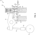
- FIG. 5 illustrates an alternative embodiment utilizing a pass-through bridge assembly 126
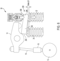
- FIG. 6 illustrates an alternative embodiment utilizing a solid bridge assembly 226.
- the brake capsule 28 generally includes an outer body 70 defining an upper chamber 72 and a lower chamber 74.
- a cap 76 seals an upper end of the upper chamber 72, and a pin 78 and a biasing mechanism 80 (e.g., a spring) are disposed in the upper chamber 72.
- the biasing mechanism 80 is configured to bias the pin 78 downward toward the lower chamber 74.
- a plunger 82 and check ball assembly 84 are disposed in the lower chamber 74.
- the plunger 82 is configured to slide along lower chamber 74 between a retracted position ( FIG. 3 ) and an extended position ( FIG. 4 ).
- a clip or stop 86 is configured to limit downward movement of plunger 82.
- Check ball assembly 84 can include a check ball 88, a seat 90, and a biasing mechanism 92 (e.g., a spring).
- the biasing mechanism 92 is configured to bias the check ball 88 toward the upper chamber 72 to seal a passage 94.
- engine brake capsule 28 is operable in a drive mode ( FIG. 3 ) and a brake mode ( FIG. 4 ).
- pressurized fluid is not supplied to engine brake capsule 28, in particular to the lower chamber 74 such that plunger 82 is collapsed or retracted into the lower chamber 74.
- pressurized fluid e.g., oil
- the pressurized fluid enters and fills lower chamber 74 via passage 94 as pin 78 biases check ball 88 downward. This forces plunger 82 downward into the extended position to contact engagement surface 58 to facilitate performing a bleeder brake operation.
- pass-through bridge assembly 126 generally includes a pin assembly 140 disposed within a bridge main body 142.
- the bridge main body 142 includes a first end 144 and a second end 146.
- the first end 144 can be configured to engage valve 24, and the pin assembly 140 is slidingly disposed within the second end 146.
- the pin assembly 140 is disposed within a cutout or bore 148 formed in the bridge second end 146 and generally includes a contact pin 150 and a valve shoe 152.
- the contact pin 150 extends through an aperture 154 formed in the bridge second end 146, and the valve shoe 152 is limited in upward movement by stops or shoulders 156 that partially define the bore 148 and aperture 154.
- the contact pin 150 includes an engagement surface 158, and the valve shoe 152 is configured to receive a portion of the valve 22.
- pressurized fluid is not supplied to engine brake capsule 28, and plunger 82 is retracted into the lower chamber 74 and does not engage contact pin 150.
- pressurized fluid is supplied to engine brake capsule 28 to force plunger 82 downward into the extended position to contact the engagement surface 158, thereby opening valve 22 to facilitate performing a bleeder brake operation.
- solid bridge assembly 226 generally includes a bridge main body 242 having a first end 244 and a second end 246.
- the first end 244 can be configured to engage and pivot on valve 24, the second end 246 can be configured to engage and pivot on valve 22.
- pressurized fluid is not supplied to engine brake capsule 28, and plunger 82 is retracted into the lower chamber 74 and does not engage bridge second end 246.
- pressurized fluid is supplied to engine brake capsule 28 to force plunger 82 downward into the extended position to contact an engagement surface 258 of the second end 246, thereby opening valve 22 to facilitate performing a bleeder brake operation.
- Described herein are systems and methods for incorporating a bleeder brake with a hydraulic lash adjuster (HLA) by utilizing a valve bridge assembly.
- a brake capsule is movable between a retracted position and an extended position, which is configured to engage a portion of the valve bridge assembly and open an exhaust valve a predetermined distance to perform a bleeder brake operation.
Landscapes
- Engineering & Computer Science (AREA)
- Mechanical Engineering (AREA)
- General Engineering & Computer Science (AREA)
- Valve-Gear Or Valve Arrangements (AREA)
- Valve Device For Special Equipments (AREA)
Claims (9)
- Ventiltriebbaugruppe (10), die konfiguriert ist, um selektiv einen Entlüftungsbremsvorgang durchzuführen, wobei die Baugruppe umfasst:einen Kipphebel (14), der konfiguriert ist, um sich um eine Kipphebelwelle (20) zu drehen;eine Nockenwelle (12), die einen Nocken aufweist, der konfiguriert ist, um eine Bewegung über eine Stößelstange (16) auf den Kipphebel zu übertragen;eine Ventilbrückenanordnung (26, 126, 226), die operativ zu einem ersten Motorventil (22) und einem zweiten Motorventil (24) gehört, wobei die Ventilbrückenanordnung konfiguriert ist, um selektiv mit dem Kipphebel in Eingriff gebracht zu werden, um mindestens ein Motorventil des ersten und des zweiten Motorventils zu öffnen, wobei die Ventilbrückenanordnung eine Hebelanordnung (40) umfasst, die in einem Brückenhauptkörper (42) angeordnet ist, und wobei die Hebelanordnung einen Hebel (48) umfasst, der durch einen Brückenstift (50) schwenkbar mit dem Brückenhauptkörper verbunden ist, wobei der Hebel konfiguriert ist, um mit dem ersten Motorventil in Eingriff zu kommen; undeine Motorbremskapsel (28), die an einem Zylinderkopf befestigt und operativ zu der Ventilbrückenanordnung gehört, wobei die Motorbremskapsel konfiguriert ist, um in einem Antriebsmodus zu arbeiten, in dem die Motorbremskapsel die Ventilbrückenanordnung nicht dazu veranlasst, das erste oder zweite Motorventil zu öffnen, und in einem Bremsmodus, in dem die Motorbremskapsel mit der Ventilbrückenanordnung in Eingriff steht, um das erste Motorventil teilweise zu öffnen, um den Ablassbremsvorgang durchzuführen, wobei im Bremsmodus der Hebel selektiv durch die Motorbremskapsel in Eingriff gebracht wird, wodurch eine Drehung um den Brückenstift und eine Aufwärtsbewegung des Brückenhauptkörpers bewirkt wird, wobei die Aufwärtsbewegung eine Drehung des Kipphebels und eine nach unten gerichtete Reaktionskraft in einen hydraulischen Spieleinsteller (HLA) Heber (18) bewirkt, um ein Aufpumpen des HLA-Hebers zu verhindern.
- Ventiltriebbaugruppe nach Anspruch 1, ferner aufweisend einen hydraulischen Spielausgleich (HLA) Heber (18), der zwischen der Nockenwelle und der Stößelstange angeordnet ist.
- Ventiltriebbaugruppe nach Anspruch 2, wobei der HLA-Heber ein deaktivierender HLA-Heber ist.
- Ventiltriebbaugruppe nach Anspruch 2, wobei der HLA-Heber ein Rollenheber ist.
- Ventiltriebbaugruppe nach Anspruch 1, wobei die Hebelanordnung ferner einen Ventilschuh (52) umfasst, der über einen Ventilschuhstift (54) schwenkbar mit dem Hebel gekoppelt ist.
- Ventiltriebbaugruppe nach Anspruch 5, wobei der Ventilschuhstift durch ein Paar von Anschlagarmen (62), das sich von dem Brückenhauptkörper erstreckt, in seiner Aufwärtsbewegung begrenzt ist.
- Ventiltriebbaugruppe nach Anspruch 1, wobei die Ventilbrückenanordnung (226) eine massive Brückenanordnung ist, die ein erstes Ende (244), das konfiguriert ist, um mit dem ersten Motorventil in Eingriff zu kommen und auf diesem zu schwenken, und ein zweites Ende (246) aufweist, das konfiguriert ist, um mit dem zweiten Motorventil in Eingriff zu kommen und auf diesem zu schwenken.
- Ventiltriebbaugruppe nach Anspruch 1, wobei die Motorbremskapsel einen äußeren Körper (70) aufweist, der eine obere Kammer (72) und eine untere Kammer (74) definiert, und wobei die Motorbremskapsel ferner einen Stift (78) und einen Vorspannmechanismus (80) aufweist, der in der oberen Kammer angeordnet ist, wobei der Vorspannmechanismus konfiguriert ist, um den Stift nach unten in Richtung der unteren Kammer vorzuspannen, wobei die Motorbremskapsel ferner einen Kolben (82) und eine Rückschlagkugelanordnung (84) aufweist, die in der unteren Kammer angeordnet sind, wobei der Kolben konfiguriert ist, um entlang der unteren Kammer zwischen einer zurückgezogenen Position und einer ausgefahrenen Position zu gleiten, wobei die Rückschlagkugelanordnung eine Rückschlagkugel (88), einen Sitz (90) und einen Vorspannmechanismus (92) aufweist, der konfiguriert ist, um die Rückschlagkugel in Richtung der oberen Kammer vorzuspannen, um einen Durchgang (94) abzudichten.
- Verfahren zum Betreiben einer Ventiltriebanordnung (10), die einen Kipphebel aufweist, der konfiguriert ist, um sich um eine Kipphebelwelle (14) zu drehen, eine Nockenwelle (12), die einen Nocken aufweist, der konfiguriert ist, um eine Bewegung auf den Kipphebel durch eine Stößelstange (16) zu übertragen, eine Ventilbrückenanordnung (26, 126, 226), die operativ zu einem ersten Motorventil (22) und einem zweiten Motorventil (24) gehört, wobei die Ventilbrückenanordnung konfiguriert ist, um selektiv durch den Kipphebel in Eingriff gebracht zu werden, um mindestens ein Motorventil des ersten und zweiten Motorventils zu öffnen, wobei die Ventilbrückenanordnung eine Hebelanordnung (40) umfasst, die in einem Brückenhauptkörper (42) angeordnet ist, und wobei die Hebelanordnung einen Hebel (48) umfasst, der durch einen Brückenstift (50) schwenkbar mit dem Brückenhauptkörper gekoppelt ist, wobei der Hebel konfiguriert ist, um mit dem ersten Motorventil in Eingriff zu kommen, und eine Motorbremskapsel (28), die an einem Zylinderkopf befestigt und operativ mit der Ventilbrückenanordnung verbunden ist, wobei das Verfahren umfasst:Arbeiten in einem Antriebsmodus, in dem die Motorbremskapsel die Ventilbrückenanordnung nicht veranlasst, das mindestens eine Motorventil zu öffnen; undArbeiten in einem Bremsmodus, in dem die Motorbremskapsel in die Ventilbrückenanordnung eingreift, um das erste Motorventil teilweise zu öffnen, um einen Entlüftungsbremsvorgang durchzuführen, wobei in dem Bremsmodus der Hebel selektiv durch die Motorbremskapsel in Eingriff gebracht wird, wodurch eine Drehung um den Brückenstift und eine Aufwärtsbewegung des Brückenhauptkörpers bewirkt wird, wobei die Aufwärtsbewegung eine Drehung des Kipphebels und eine Abwärtsreaktionskraft in einen hydraulischen Spieleinsteller (HLA-)Heber bewirkt, um ein Aufpumpen des HLA-Hebers davon zu verhindern.
Applications Claiming Priority (2)
| Application Number | Priority Date | Filing Date | Title |
|---|---|---|---|
| US201862697119P | 2018-07-12 | 2018-07-12 | |
| PCT/US2019/041649 WO2020014637A1 (en) | 2018-07-12 | 2019-07-12 | Balanced bridge bleeder brake with hla |
Publications (3)
| Publication Number | Publication Date |
|---|---|
| EP3821114A1 EP3821114A1 (de) | 2021-05-19 |
| EP3821114A4 EP3821114A4 (de) | 2022-08-24 |
| EP3821114B1 true EP3821114B1 (de) | 2024-12-18 |
Family
ID=69143003
Family Applications (1)
| Application Number | Title | Priority Date | Filing Date |
|---|---|---|---|
| EP19834097.8A Active EP3821114B1 (de) | 2018-07-12 | 2019-07-12 | Entlüftungsbremse mit vorgesteuerter brücke mit hla |
Country Status (3)
| Country | Link |
|---|---|
| EP (1) | EP3821114B1 (de) |
| CN (1) | CN112639255B (de) |
| WO (1) | WO2020014637A1 (de) |
Families Citing this family (2)
| Publication number | Priority date | Publication date | Assignee | Title |
|---|---|---|---|---|
| DE112022002161T5 (de) * | 2021-06-11 | 2024-02-01 | Eaton Intelligent Power Limited | Hydraulikkapseln für ventiltriebanordnung |
| IT202400000840A1 (it) * | 2024-01-18 | 2025-07-18 | Fpt Ind Spa | Un gruppo freno motore |
Family Cites Families (14)
| Publication number | Priority date | Publication date | Assignee | Title |
|---|---|---|---|---|
| GB9815599D0 (en) * | 1998-07-20 | 1998-09-16 | Cummins Engine Co Ltd | Compression engine braking system |
| US7246585B2 (en) * | 2005-04-12 | 2007-07-24 | Delphi Technologies, Inc. | Valve-deactivating hydraulic lifter having a vented internal lost motion spring |
| US7617807B2 (en) * | 2005-11-30 | 2009-11-17 | Ford Global Technologies, Llc | Engine and valvetrain with dual pushrod lifters and independent lash adjustment |
| CN204961000U (zh) * | 2012-09-24 | 2016-01-13 | 雅各布斯车辆系统公司 | 带有自动复位的集成失动式摇臂制动器系统 |
| US10247064B2 (en) * | 2014-02-14 | 2019-04-02 | Eaton Intelligent Power Limited | Rocker arm assembly for engine braking |
| BR122020018178B1 (pt) * | 2014-06-10 | 2023-10-10 | Jacobs Vehicle Systems, Inc | Sistema para uso em um motor de combustão interna e método para acionar pelo menos uma válvula de motor em um motor de combustão interna |
| BR112017005467B1 (pt) * | 2014-09-18 | 2022-05-17 | Eaton Srl | Conjunto de balancim de válvula de escape |
| EP3207226A4 (de) * | 2014-10-15 | 2018-05-16 | Shanghai Universoon Autoparts Co., Ltd | Motorbremsverfahren und system |
| JP2018503025A (ja) * | 2015-01-21 | 2018-02-01 | イートン コーポレーションEaton Corporation | エンジンブレーキ用ロッカーアームアセンブリ |
| EP3298251B1 (de) * | 2015-05-18 | 2020-01-01 | Eaton Intelligent Power Limited | Kiphebel mit einem als akumulator wirkende öl-entlastungsventil |
| WO2017064690A1 (en) * | 2015-10-15 | 2017-04-20 | Eaton S.R.L | Rocker arm assembly for engine brake |
| DE112016006466T5 (de) * | 2016-03-16 | 2018-10-31 | Eaton Intelligent Power Limited | Kipphebelanordnung |
| CN113803127B (zh) * | 2016-04-07 | 2024-02-13 | 伊顿智能动力有限公司 | 摇臂组合件 |
| WO2019228671A1 (en) * | 2018-05-31 | 2019-12-05 | Eaton Intelligent Power Limited | Primary and auxiliary variable valve actuation valvetrain |
-
2019
- 2019-07-12 EP EP19834097.8A patent/EP3821114B1/de active Active
- 2019-07-12 WO PCT/US2019/041649 patent/WO2020014637A1/en not_active Ceased
- 2019-07-12 CN CN201980056996.9A patent/CN112639255B/zh active Active
Also Published As
| Publication number | Publication date |
|---|---|
| EP3821114A1 (de) | 2021-05-19 |
| WO2020014637A1 (en) | 2020-01-16 |
| CN112639255B (zh) | 2023-01-17 |
| CN112639255A (zh) | 2021-04-09 |
| EP3821114A4 (de) | 2022-08-24 |
Similar Documents
| Publication | Publication Date | Title |
|---|---|---|
| US11339690B2 (en) | Balanced bridge bleeder brake with HLA | |
| US10858963B2 (en) | Rocker arm assembly for engine braking | |
| US11598228B2 (en) | Rocker arm assembly with valve bridge | |
| US20160146074A1 (en) | Engine brake lash adjuster device and method | |
| US10690024B2 (en) | Rocker arm assembly for engine braking | |
| WO2017177102A1 (en) | Rocker arm assembly | |
| US11022008B2 (en) | Ball engine brake mechanism | |
| EP3821114B1 (de) | Entlüftungsbremse mit vorgesteuerter brücke mit hla | |
| US10927724B2 (en) | Rocker arm assembly | |
| CN113167137B (zh) | 用于引擎制动的摇臂组件 | |
| US11401839B2 (en) | Rocker based bleeder engine brake | |
| US11549404B2 (en) | Ball engine decompression mechanism | |
| US12071867B2 (en) | Rocker arm assembly with valve bridge | |
| US11852047B2 (en) | Rocker arm assembly with lost motion spring capsule | |
| US11859519B2 (en) | Lash setting features for castellation mechanism |
Legal Events
| Date | Code | Title | Description |
|---|---|---|---|
| STAA | Information on the status of an ep patent application or granted ep patent |
Free format text: STATUS: THE INTERNATIONAL PUBLICATION HAS BEEN MADE |
|
| PUAI | Public reference made under article 153(3) epc to a published international application that has entered the european phase |
Free format text: ORIGINAL CODE: 0009012 |
|
| STAA | Information on the status of an ep patent application or granted ep patent |
Free format text: STATUS: REQUEST FOR EXAMINATION WAS MADE |
|
| 17P | Request for examination filed |
Effective date: 20210209 |
|
| AK | Designated contracting states |
Kind code of ref document: A1 Designated state(s): AL AT BE BG CH CY CZ DE DK EE ES FI FR GB GR HR HU IE IS IT LI LT LU LV MC MK MT NL NO PL PT RO RS SE SI SK SM TR |
|
| DAV | Request for validation of the european patent (deleted) | ||
| DAX | Request for extension of the european patent (deleted) | ||
| A4 | Supplementary search report drawn up and despatched |
Effective date: 20220727 |
|
| RIC1 | Information provided on ipc code assigned before grant |
Ipc: F01L 1/18 20060101ALI20220722BHEP Ipc: F01L 1/26 20060101ALI20220722BHEP Ipc: F01L 1/24 20060101ALI20220722BHEP Ipc: F01L 13/06 20060101AFI20220722BHEP |
|
| P01 | Opt-out of the competence of the unified patent court (upc) registered |
Effective date: 20230521 |
|
| GRAP | Despatch of communication of intention to grant a patent |
Free format text: ORIGINAL CODE: EPIDOSNIGR1 |
|
| STAA | Information on the status of an ep patent application or granted ep patent |
Free format text: STATUS: GRANT OF PATENT IS INTENDED |
|
| INTG | Intention to grant announced |
Effective date: 20240417 |
|
| GRAJ | Information related to disapproval of communication of intention to grant by the applicant or resumption of examination proceedings by the epo deleted |
Free format text: ORIGINAL CODE: EPIDOSDIGR1 |
|
| STAA | Information on the status of an ep patent application or granted ep patent |
Free format text: STATUS: REQUEST FOR EXAMINATION WAS MADE |
|
| GRAP | Despatch of communication of intention to grant a patent |
Free format text: ORIGINAL CODE: EPIDOSNIGR1 |
|
| STAA | Information on the status of an ep patent application or granted ep patent |
Free format text: STATUS: GRANT OF PATENT IS INTENDED |
|
| INTC | Intention to grant announced (deleted) | ||
| INTG | Intention to grant announced |
Effective date: 20240711 |
|
| GRAS | Grant fee paid |
Free format text: ORIGINAL CODE: EPIDOSNIGR3 |
|
| GRAA | (expected) grant |
Free format text: ORIGINAL CODE: 0009210 |
|
| STAA | Information on the status of an ep patent application or granted ep patent |
Free format text: STATUS: THE PATENT HAS BEEN GRANTED |
|
| AK | Designated contracting states |
Kind code of ref document: B1 Designated state(s): AL AT BE BG CH CY CZ DE DK EE ES FI FR GB GR HR HU IE IS IT LI LT LU LV MC MK MT NL NO PL PT RO RS SE SI SK SM TR |
|
| REG | Reference to a national code |
Ref country code: CH Ref legal event code: EP |
|
| REG | Reference to a national code |
Ref country code: DE Ref legal event code: R096 Ref document number: 602019063751 Country of ref document: DE |
|
| REG | Reference to a national code |
Ref country code: IE Ref legal event code: FG4D |
|
| REG | Reference to a national code |
Ref country code: LT Ref legal event code: MG9D |
|
| PG25 | Lapsed in a contracting state [announced via postgrant information from national office to epo] |
Ref country code: HR Free format text: LAPSE BECAUSE OF FAILURE TO SUBMIT A TRANSLATION OF THE DESCRIPTION OR TO PAY THE FEE WITHIN THE PRESCRIBED TIME-LIMIT Effective date: 20241218 |
|
| PG25 | Lapsed in a contracting state [announced via postgrant information from national office to epo] |
Ref country code: FI Free format text: LAPSE BECAUSE OF FAILURE TO SUBMIT A TRANSLATION OF THE DESCRIPTION OR TO PAY THE FEE WITHIN THE PRESCRIBED TIME-LIMIT Effective date: 20241218 |
|
| PG25 | Lapsed in a contracting state [announced via postgrant information from national office to epo] |
Ref country code: BG Free format text: LAPSE BECAUSE OF FAILURE TO SUBMIT A TRANSLATION OF THE DESCRIPTION OR TO PAY THE FEE WITHIN THE PRESCRIBED TIME-LIMIT Effective date: 20241218 |
|
| PG25 | Lapsed in a contracting state [announced via postgrant information from national office to epo] |
Ref country code: NO Free format text: LAPSE BECAUSE OF FAILURE TO SUBMIT A TRANSLATION OF THE DESCRIPTION OR TO PAY THE FEE WITHIN THE PRESCRIBED TIME-LIMIT Effective date: 20250318 |
|
| REG | Reference to a national code |
Ref country code: NL Ref legal event code: MP Effective date: 20241218 |
|
| PG25 | Lapsed in a contracting state [announced via postgrant information from national office to epo] |
Ref country code: LV Free format text: LAPSE BECAUSE OF FAILURE TO SUBMIT A TRANSLATION OF THE DESCRIPTION OR TO PAY THE FEE WITHIN THE PRESCRIBED TIME-LIMIT Effective date: 20241218 Ref country code: GR Free format text: LAPSE BECAUSE OF FAILURE TO SUBMIT A TRANSLATION OF THE DESCRIPTION OR TO PAY THE FEE WITHIN THE PRESCRIBED TIME-LIMIT Effective date: 20250319 |
|
| PG25 | Lapsed in a contracting state [announced via postgrant information from national office to epo] |
Ref country code: RS Free format text: LAPSE BECAUSE OF FAILURE TO SUBMIT A TRANSLATION OF THE DESCRIPTION OR TO PAY THE FEE WITHIN THE PRESCRIBED TIME-LIMIT Effective date: 20250318 |
|
| PG25 | Lapsed in a contracting state [announced via postgrant information from national office to epo] |
Ref country code: NL Free format text: LAPSE BECAUSE OF FAILURE TO SUBMIT A TRANSLATION OF THE DESCRIPTION OR TO PAY THE FEE WITHIN THE PRESCRIBED TIME-LIMIT Effective date: 20241218 |
|
| REG | Reference to a national code |
Ref country code: AT Ref legal event code: MK05 Ref document number: 1752381 Country of ref document: AT Kind code of ref document: T Effective date: 20241218 |
|
| PG25 | Lapsed in a contracting state [announced via postgrant information from national office to epo] |
Ref country code: SM Free format text: LAPSE BECAUSE OF FAILURE TO SUBMIT A TRANSLATION OF THE DESCRIPTION OR TO PAY THE FEE WITHIN THE PRESCRIBED TIME-LIMIT Effective date: 20241218 |
|
| PG25 | Lapsed in a contracting state [announced via postgrant information from national office to epo] |
Ref country code: PL Free format text: LAPSE BECAUSE OF FAILURE TO SUBMIT A TRANSLATION OF THE DESCRIPTION OR TO PAY THE FEE WITHIN THE PRESCRIBED TIME-LIMIT Effective date: 20241218 |
|
| PG25 | Lapsed in a contracting state [announced via postgrant information from national office to epo] |
Ref country code: ES Free format text: LAPSE BECAUSE OF FAILURE TO SUBMIT A TRANSLATION OF THE DESCRIPTION OR TO PAY THE FEE WITHIN THE PRESCRIBED TIME-LIMIT Effective date: 20241218 |
|
| PG25 | Lapsed in a contracting state [announced via postgrant information from national office to epo] |
Ref country code: IS Free format text: LAPSE BECAUSE OF FAILURE TO SUBMIT A TRANSLATION OF THE DESCRIPTION OR TO PAY THE FEE WITHIN THE PRESCRIBED TIME-LIMIT Effective date: 20250418 |
|
| PG25 | Lapsed in a contracting state [announced via postgrant information from national office to epo] |
Ref country code: PT Free format text: LAPSE BECAUSE OF FAILURE TO SUBMIT A TRANSLATION OF THE DESCRIPTION OR TO PAY THE FEE WITHIN THE PRESCRIBED TIME-LIMIT Effective date: 20250421 |
|
| PG25 | Lapsed in a contracting state [announced via postgrant information from national office to epo] |
Ref country code: EE Free format text: LAPSE BECAUSE OF FAILURE TO SUBMIT A TRANSLATION OF THE DESCRIPTION OR TO PAY THE FEE WITHIN THE PRESCRIBED TIME-LIMIT Effective date: 20241218 |
|
| PG25 | Lapsed in a contracting state [announced via postgrant information from national office to epo] |
Ref country code: RO Free format text: LAPSE BECAUSE OF FAILURE TO SUBMIT A TRANSLATION OF THE DESCRIPTION OR TO PAY THE FEE WITHIN THE PRESCRIBED TIME-LIMIT Effective date: 20241218 Ref country code: AT Free format text: LAPSE BECAUSE OF FAILURE TO SUBMIT A TRANSLATION OF THE DESCRIPTION OR TO PAY THE FEE WITHIN THE PRESCRIBED TIME-LIMIT Effective date: 20241218 |
|
| PG25 | Lapsed in a contracting state [announced via postgrant information from national office to epo] |
Ref country code: SK Free format text: LAPSE BECAUSE OF FAILURE TO SUBMIT A TRANSLATION OF THE DESCRIPTION OR TO PAY THE FEE WITHIN THE PRESCRIBED TIME-LIMIT Effective date: 20241218 |
|
| PG25 | Lapsed in a contracting state [announced via postgrant information from national office to epo] |
Ref country code: CZ Free format text: LAPSE BECAUSE OF FAILURE TO SUBMIT A TRANSLATION OF THE DESCRIPTION OR TO PAY THE FEE WITHIN THE PRESCRIBED TIME-LIMIT Effective date: 20241218 |
|
| PG25 | Lapsed in a contracting state [announced via postgrant information from national office to epo] |
Ref country code: IT Free format text: LAPSE BECAUSE OF FAILURE TO SUBMIT A TRANSLATION OF THE DESCRIPTION OR TO PAY THE FEE WITHIN THE PRESCRIBED TIME-LIMIT Effective date: 20241218 |
|
| PG25 | Lapsed in a contracting state [announced via postgrant information from national office to epo] |
Ref country code: SE Free format text: LAPSE BECAUSE OF FAILURE TO SUBMIT A TRANSLATION OF THE DESCRIPTION OR TO PAY THE FEE WITHIN THE PRESCRIBED TIME-LIMIT Effective date: 20241218 |
|
| REG | Reference to a national code |
Ref country code: DE Ref legal event code: R097 Ref document number: 602019063751 Country of ref document: DE |
|
| PG25 | Lapsed in a contracting state [announced via postgrant information from national office to epo] |
Ref country code: DK Free format text: LAPSE BECAUSE OF FAILURE TO SUBMIT A TRANSLATION OF THE DESCRIPTION OR TO PAY THE FEE WITHIN THE PRESCRIBED TIME-LIMIT Effective date: 20241218 |
|
| PGFP | Annual fee paid to national office [announced via postgrant information from national office to epo] |
Ref country code: DE Payment date: 20250620 Year of fee payment: 7 |
|
| PLBE | No opposition filed within time limit |
Free format text: ORIGINAL CODE: 0009261 |
|
| STAA | Information on the status of an ep patent application or granted ep patent |
Free format text: STATUS: NO OPPOSITION FILED WITHIN TIME LIMIT |
|
| REG | Reference to a national code |
Ref country code: CH Ref legal event code: L10 Free format text: ST27 STATUS EVENT CODE: U-0-0-L10-L00 (AS PROVIDED BY THE NATIONAL OFFICE) Effective date: 20251029 |
|
| 26N | No opposition filed |
Effective date: 20250919 |
|
| REG | Reference to a national code |
Ref country code: CH Ref legal event code: H13 Free format text: ST27 STATUS EVENT CODE: U-0-0-H10-H13 (AS PROVIDED BY THE NATIONAL OFFICE) Effective date: 20260224 |
|
| PG25 | Lapsed in a contracting state [announced via postgrant information from national office to epo] |
Ref country code: LU Free format text: LAPSE BECAUSE OF NON-PAYMENT OF DUE FEES Effective date: 20250712 |
|
| GBPC | Gb: european patent ceased through non-payment of renewal fee |
Effective date: 20250712 |