EP3820614B1 - Pipettiervorrichtung zur impulsartigen pipettierung mit einer basierend auf einer erfassung der kolbenposition geregelten pipettierkolbenbewegung - Google Patents
Pipettiervorrichtung zur impulsartigen pipettierung mit einer basierend auf einer erfassung der kolbenposition geregelten pipettierkolbenbewegung Download PDFInfo
- Publication number
- EP3820614B1 EP3820614B1 EP19748709.3A EP19748709A EP3820614B1 EP 3820614 B1 EP3820614 B1 EP 3820614B1 EP 19748709 A EP19748709 A EP 19748709A EP 3820614 B1 EP3820614 B1 EP 3820614B1
- Authority
- EP
- European Patent Office
- Prior art keywords
- pipetting
- piston
- dosing
- dispensing
- liquid
- Prior art date
- Legal status (The legal status is an assumption and is not a legal conclusion. Google has not performed a legal analysis and makes no representation as to the accuracy of the status listed.)
- Active
Links
Images


Classifications
-
- B—PERFORMING OPERATIONS; TRANSPORTING
- B01—PHYSICAL OR CHEMICAL PROCESSES OR APPARATUS IN GENERAL
- B01L—CHEMICAL OR PHYSICAL LABORATORY APPARATUS FOR GENERAL USE
- B01L3/00—Containers or dishes for laboratory use, e.g. laboratory glassware; Droppers
- B01L3/02—Burettes; Pipettes
- B01L3/021—Pipettes, i.e. with only one conduit for withdrawing and redistributing liquids
- B01L3/0217—Pipettes, i.e. with only one conduit for withdrawing and redistributing liquids of the plunger pump type
- B01L3/0227—Details of motor drive means
-
- B—PERFORMING OPERATIONS; TRANSPORTING
- B01—PHYSICAL OR CHEMICAL PROCESSES OR APPARATUS IN GENERAL
- B01L—CHEMICAL OR PHYSICAL LABORATORY APPARATUS FOR GENERAL USE
- B01L3/00—Containers or dishes for laboratory use, e.g. laboratory glassware; Droppers
- B01L3/02—Burettes; Pipettes
- B01L3/021—Pipettes, i.e. with only one conduit for withdrawing and redistributing liquids
- B01L3/0217—Pipettes, i.e. with only one conduit for withdrawing and redistributing liquids of the plunger pump type
- B01L3/0237—Details of electronic control, e.g. relating to user interface
-
- B—PERFORMING OPERATIONS; TRANSPORTING
- B01—PHYSICAL OR CHEMICAL PROCESSES OR APPARATUS IN GENERAL
- B01L—CHEMICAL OR PHYSICAL LABORATORY APPARATUS FOR GENERAL USE
- B01L3/00—Containers or dishes for laboratory use, e.g. laboratory glassware; Droppers
- B01L3/02—Burettes; Pipettes
- B01L3/0241—Drop counters; Drop formers
- B01L3/0268—Drop counters; Drop formers using pulse dispensing or spraying, eg. inkjet type, piezo actuated ejection of droplets from capillaries
-
- G—PHYSICS
- G01—MEASURING; TESTING
- G01N—INVESTIGATING OR ANALYSING MATERIALS BY DETERMINING THEIR CHEMICAL OR PHYSICAL PROPERTIES
- G01N35/00—Automatic analysis not limited to methods or materials provided for in any single one of groups G01N1/00 - G01N33/00; Handling materials therefor
- G01N35/10—Devices for transferring samples or any liquids to, in, or from, the analysis apparatus, e.g. suction devices, injection devices
- G01N35/1009—Characterised by arrangements for controlling the aspiration or dispense of liquids
- G01N35/1011—Control of the position or alignment of the transfer device
-
- G—PHYSICS
- G01—MEASURING; TESTING
- G01N—INVESTIGATING OR ANALYSING MATERIALS BY DETERMINING THEIR CHEMICAL OR PHYSICAL PROPERTIES
- G01N35/00—Automatic analysis not limited to methods or materials provided for in any single one of groups G01N1/00 - G01N33/00; Handling materials therefor
- G01N35/10—Devices for transferring samples or any liquids to, in, or from, the analysis apparatus, e.g. suction devices, injection devices
- G01N35/1009—Characterised by arrangements for controlling the aspiration or dispense of liquids
- G01N35/1016—Control of the volume dispensed or introduced
-
- B—PERFORMING OPERATIONS; TRANSPORTING
- B01—PHYSICAL OR CHEMICAL PROCESSES OR APPARATUS IN GENERAL
- B01L—CHEMICAL OR PHYSICAL LABORATORY APPARATUS FOR GENERAL USE
- B01L2200/00—Solutions for specific problems relating to chemical or physical laboratory apparatus
- B01L2200/14—Process control and prevention of errors
-
- B—PERFORMING OPERATIONS; TRANSPORTING
- B01—PHYSICAL OR CHEMICAL PROCESSES OR APPARATUS IN GENERAL
- B01L—CHEMICAL OR PHYSICAL LABORATORY APPARATUS FOR GENERAL USE
- B01L2300/00—Additional constructional details
- B01L2300/06—Auxiliary integrated devices, integrated components
- B01L2300/0627—Sensor or part of a sensor is integrated
- B01L2300/0663—Whole sensors
-
- B—PERFORMING OPERATIONS; TRANSPORTING
- B01—PHYSICAL OR CHEMICAL PROCESSES OR APPARATUS IN GENERAL
- B01L—CHEMICAL OR PHYSICAL LABORATORY APPARATUS FOR GENERAL USE
- B01L2400/00—Moving or stopping fluids
- B01L2400/04—Moving fluids with specific forces or mechanical means
- B01L2400/0403—Moving fluids with specific forces or mechanical means specific forces
- B01L2400/043—Moving fluids with specific forces or mechanical means specific forces magnetic forces
-
- B—PERFORMING OPERATIONS; TRANSPORTING
- B01—PHYSICAL OR CHEMICAL PROCESSES OR APPARATUS IN GENERAL
- B01L—CHEMICAL OR PHYSICAL LABORATORY APPARATUS FOR GENERAL USE
- B01L2400/00—Moving or stopping fluids
- B01L2400/04—Moving fluids with specific forces or mechanical means
- B01L2400/0475—Moving fluids with specific forces or mechanical means specific mechanical means and fluid pressure
- B01L2400/0478—Moving fluids with specific forces or mechanical means specific mechanical means and fluid pressure pistons
-
- G—PHYSICS
- G01—MEASURING; TESTING
- G01N—INVESTIGATING OR ANALYSING MATERIALS BY DETERMINING THEIR CHEMICAL OR PHYSICAL PROPERTIES
- G01N35/00—Automatic analysis not limited to methods or materials provided for in any single one of groups G01N1/00 - G01N33/00; Handling materials therefor
- G01N35/10—Devices for transferring samples or any liquids to, in, or from, the analysis apparatus, e.g. suction devices, injection devices
- G01N2035/1027—General features of the devices
- G01N2035/1034—Transferring microquantities of liquid
Definitions
- the present invention relates to a pipetting device for pulsed pipetting of dosing liquids in small dosing volumes of less than 2 ⁇ l using a pressure-variable working gas according to the preamble of claim 1.
- the control device can be used to specifically control the motion drive to effect a pipetting process in order to move the pipetting piston in the desired manner by appropriately controlling the motion drive and in turn to change the pressure of the working gas in the desired manner.
- a pulse-like dispensing in the sense of the present invention is known from US 2001/0016358 A1
- a piezo actuator delivers a direct physical impact to the meniscus of the dosing liquid provided in the pipetting device that is further away from the pipetting opening, thereby causing a drop to be ejected from the meniscus closer to the pipetting opening at the opposite longitudinal end of the dosing liquid column provided.
- a pipetting device with a pipetting piston driven by a linear motor is known, which is the rotor of the linear motor formed on the pipetting device.
- the disclosed EP 2 656 917 A1 only a piston movement for a conventional pipetting method, which functions according to different physical principles than the pulsed pipetting used in the present application. Findings from the conventional pipetting method and its execution cannot be transferred between the different pipetting methods due to the different physical principles between quasi-synchronous conventional pipetting on the one hand and pulsed pipetting on the other. In contrast to pulsed pipetting, in conventional pipetting the movement of the pipetting piston is proportional to the amount of liquid being pipetted.
- the piston movement for pulsed pipetting with a duration of 35 ms or less is preferably the only piston movement of the pipetting process that causes a movement of dosing liquid of less than 2 ⁇ l through the pipetting opening and thus a corresponding dosing.
- the term "detected value" of a quantity is synonymous with the term “actual value” of that quantity.
- a “pressure pulse” or “pulse-like” pipetting is defined as a pressure pulse in the working gas that causes aspiration of dosing liquid into the pipette tip or dispensing of dosing liquid from the pipette tip, with a total pulse duration of no more than 40 ms. Due to inertia-related decay effects on the working gas, the Duration of the pressure pulse is usually longer than the duration of the pipetting piston movement causing the pressure pulse.
- the duration of the pipetting piston movement is the time period between leaving a pipetting piston reference position or pipetting piston start position, in which the pipetting piston is located immediately before the pipetting process, and the pipetting piston coming to a standstill again.
- a dead point of a reversal of movement, at which a piston speed of 0 is present at certain points, is not a standstill of the pipetting piston within the meaning of the present application.
- the reference pressure prevails in the working gas, at which no dosing liquid passes through the pipetting opening and at which any dosing liquid present in the pipetting tip is preferably kept essentially motionless.
- the pressure pulse can preferably comprise an overpressure component and a negative pressure component.
- the overpressure component precedes the negative pressure component in the pressure pulse.
- Both the overpressure component and the underpressure component are within the specified pressure pulse time window of a maximum of 40 ms.
- the pipetting piston target position curve of a pipetting process can contain pipetting piston target positions on both sides of the start position and/or the end position of the pipetting piston at the beginning or at the end of the pipetting process.
- all pipetting piston target positions located on the dispensing side of the start and end position preferably precede all pipetting piston target positions located on the aspiration side of the start and end position.
- the end position of the pipetting piston for a dispensing process is located away from its start position on the dispensing side of the start position, the entire pipetting piston target position curve for generating the pipetting pressure pulse can be located on one and the same side of the start position. In that case, however, the pipetting piston target position curve is always on both sides: dispensing side and aspiration side, of the end position of the piston movement.
- the pipetting piston target position curve preferably comprises at least two, particularly preferably exactly two dead points of a movement reversal.
- the pipetting piston moves only in the dispensing direction in the first phase, then only in the aspiration direction in the second phase and finally only in the dispensing direction again in the third phase.
- the third phase is generally the shortest in time with the smallest movement stroke of the piston.
- the direction of movement of the pipetting piston changes only once during a pipetting process, for example in a dispensing process from a movement in the dispensing direction to a movement in the aspiration direction.
- the third phase mentioned above can then be omitted.
- Pulse-like dispensing is a dispensing that differs from the conventional pipetting operation.
- the overpressure pulse of the working gas causes a pressure surge from the working gas to be exerted on the side of the dosing liquid held in a pipetting device that is facing away from a dosing opening.
- This pressure surge propagates through the incompressible dosing liquid quantity to a meniscus of the dosing liquid quantity taken up that is closer to the pipette opening and leads to a drop of dosing liquid being ejected there.
- the ejection of the dosing liquid drop can be triggered in a defined manner by a whip-like piston movement, in which a strongly accelerated piston movement in the dispensing direction is immediately followed by a strongly accelerated piston movement in the aspiration direction.
- the resulting negative pressure component in the pressure pulse curve of the working gas is smaller in magnitude and not longer in time, preferably even shorter, than the preceding positive pressure component.
- aliquoting always includes a plurality of dispensing processes, namely exactly one for each amount of dosing liquid dispensed during aliquoting.
- dosing liquid taken up by the pipetting device is pushed out by increasing the pressure in the working gas until either a drop detaches from the pipetting opening due to gravity or dosing liquid is dosed through the pipetting opening onto a substrate wetted by the dosing liquid or into an already existing liquid, from which the pipetting opening is lifted after the predetermined dosing quantity has been dispensed.
- dosing liquid usually only moves in the dispensing direction through the pipetting opening as long as the pipetting piston is also moved in the dispensing direction (increasing the pressure in the working gas).
- the pulse-like dispensing on which the present invention is based is asynchronous in this respect, i.e. in response to a pulse-like, sudden generation of an overpressure pulse in the working gas, the drop of dosing liquid is usually only thrown off the absorbed dosing liquid quantity while the overpressure pulse is at least beginning to subside or has even subsided.
- the dispensing of the drop of dosing liquid is therefore not synchronized with a movement of the pipetting piston.
- a pipetting piston target position curve can be determined in advance for different dosing liquids or dosing liquid classes as well as for different quantities to be dosed and stored in a data memory of the pipetting device so that it can be retrieved.
- the liquid quantities to be dosed are usually dispensed as drops with an acceleration of the amount of dosing liquid held in the pipetting device, which is added to the acceleration due to gravity when dispensing in the direction of gravity. This means that the droplets of dosing liquid separated from the amount of dosing liquid held by the pipetting device during pulse-like dispensing move away from the pipetting device faster when dispensing in the direction of gravity than they would in free fall.
- this is a negative pressure compared to the ambient pressure, so that dosing liquid flows into the pipette tip from a dosing liquid supply in which the pipette opening of the pipette tip is immersed, driven by the differential pressure between the pressure of the working gas and the ambient pressure.
- this is a positive pressure compared to the ambient pressure, so that dosing liquid taken up in the pipette tip exits through the pipette opening of the pipette tip, driven by the differential pressure between the pressure of the working gas and the ambient pressure.
- the compressible working gas thus acts like a gas spring. Due to the small but existing time offset between the piston movement and the movement of the meniscus of the dosing liquid in the pipette tip, conventional pipetting of dosing liquid is referred to below as a quasi-synchronous operating mode.
- the separation of the dosing liquid to be dispensed from the pipette tip can be achieved by using the inertial forces of the dosing liquid.
- the piston is moved in the dispensing direction for a predetermined time and then, when separation of the dosing liquid displaced from the pipette tip is desired, it is stopped as suddenly as possible.
- the mass inertia of the dosing liquid already displaced, which has increased due to the previous piston movement, is still in the dispensing movement, can then lead to the dosing liquid being cut off at the pipetting opening and ultimately to the opening breaking off.
- the relationship between piston movement and the dosing liquid displaced by the working gas is usually determined empirically for different liquid classes and is stored in a data memory of the pipetting device.
- the volume swept over by the dosing-side piston surface during the movement of the piston in the pipetting direction does not usually exceed the actually pipetted volume of dosing liquid by more than 5%.
- the ratio of pipetting volume to actually pipetted volume of dosing liquid is therefore usually no greater than 1.05.
- this dispensing of dosing liquid using inertia forces of the dispensing no longer functions reliably for individual dosing volumes of less than 3 to 5 ⁇ l, since due to the low mass the achievable inertia forces can no longer sufficiently overcome other force influences, in particular due to surface tension, to ensure a safe, repeatable detachment of such small dosing liquid quantities.
- the pipetting devices described here must be distinguished from the so-called “dispensers” or “dispensers”, which usually only dispense dosing liquids, but cannot aspirate them.
- Dispensers receive the The dosing liquid to be dispensed is usually supplied via supply channels from a supply which is in flow connection with a dosing chamber of the dispenser which can be changed by the piston.
- pipetting devices in which the dosing-side end surface of the piston is in direct contact with the dosing liquid to be pipetted. There is then no working gas between the piston and the dosing liquid.
- the pipetting method is referred to in the specialist world by the English term "positive displacement".
- gas inclusion in the pipetting volume during aspiration cannot be completely ruled out, so that even with positive displacement pipetting, gas or air bubbles can occur in the aspirated dosing liquid, which then has a negative effect on the achievable pipetting accuracy due to the deviation from the target state.
- the pipetting accuracy achievable with positive displacement pipetting is extremely low if the dosing liquid tends to foam.
- the pipetting piston is wetted by the dosing liquid, when the dosing liquid to be pipetted is to be changed, not only a pipetting tip but also the pipetting piston must be changed, which means considerable assembly effort and consequently considerable costs.
- the pipetting method of generic pipetting devices with a working gas between the piston and the dosing liquid is referred to in the professional world as "air displacement", although the working gas does not necessarily have to be air, but can also be an inert gas or a quasi-inert gas, such as nitrogen.
- air displacement the working gas does not necessarily have to be air, but can also be an inert gas or a quasi-inert gas, such as nitrogen.
- the pipetting piston is permanently and completely separated. There is therefore no or only a negligible risk of contamination.
- the present pipetting device according to the invention must also be distinguished from those that use a column of a system liquid as a piston. Such system liquids pose a certain degree of contamination risk, since it cannot sometimes be ruled out that system liquid, i.e. part of a piston that is also liquid, gets into the dosing liquid to be pipetted.
- the piston of the pipetting device according to the present invention is designed as a solid body at least in sections, preferably completely, to avoid a risk of contamination. If only sections are designed as a solid body, at least the dosing-side end surface of the piston facing the dosing liquid is designed as a solid body in order to prevent transfer from liquid to liquid.
- dosing liquid When dispensing small doses of dosing liquid in pulses, undesirable side effects can occur depending on the dosing liquid selected, for example depending on its viscosity, density and/or surface tension, and also depending on the parameters of the overpressure pulse and possibly the subsequent underpressure pulse. For example, instead of just a single desired dosing drop at the dispensing meniscus closer to the pipette opening, dosing liquid can be nebulized or dosing liquid can be dispensed through a dosing drop accompanied by undesirable satellite droplets, which is associated with an undesirable reduction in the achievable dosing quantity accuracy.
- Dispensing within the meaning of the present application is therefore understood to mean the splash- and mist-free release of the dosing liquid in a drop.
- the pipetting device can have a permanently installed pipetting channel with a pipetting tip with a pipetting opening formed at the end of the pipetting channel.
- the pipetting device is preferably designed to detachably attach interchangeable pipetting tips to to couple the pipetting channel.
- the pipetting device has a coupling formation through which the pipetting channel passes for temporarily coupling a pipetting tip. If a pipetting tip is coupled to the coupling formation, the pipetting tip extends the device's own pipetting channel and is temporarily, i.e. for the duration of its coupling, part of the pipetting channel of the pipetting device.
- the pipetting tip is preferably a so-called “disposable” pipetting tip, i.e. a one-way or throw-away pipetting tip which is disposed of after a single dispensing or aliquoting.
- the pipetting device is designed not only for pulse-like dispensing, but also for conventional aspiration, in which the dosing liquid in the receiving space and initially into it follows the piston movement synchronously or quasi-synchronously in the sense explained above.
- the provision of dosing liquid in the pipetting device, in particular in a pipetting tip received therein, can then take place by quasi-synchronous aspiration of dosing liquid through the pipetting opening of the pipetting device into the receiving space of the pipetting device.
- the pipetting device is preferably designed both for pulse-like dispensing in asynchronous operation and for conventional dispensing in quasi-synchronous operation, so that small dosing liquid quantities of less than 2 ⁇ l, down to a few tens of nanoliters, as well as large liquid quantities of several hundred microliters can be dispensed with repeatable accuracy using the pipetting device according to the invention.
- the switchover between asynchronous and quasi-synchronous operation is carried out by appropriately controlling the pipetting piston movement drive by the control device.
- the control device can also be designed to regulate the control of the movement drive in accordance with the position signal output by the position detection device only in pulse-like pipetting operation.
- the control device can continue to control the movement drive due to the close correlation between the volume swept by the piston and the dispensed or aspirated volume. position-dependently according to a signal from at least one position sensor indicating the position of the pipetting piston and thus regulating the piston position.
- the control device can control the movement drive according to a pressure signal representing the pressure of the working gas. If the piston acceleration and movement are sufficiently slow, dispensing, as well as aspiration, takes place quasi-synchronously.
- the values to be set by the control device on the movement drive for a desired piston acceleration and/or piston speed can be determined by testing for different liquid classes without great effort.
- the control device can be designed to move the piston at a maximum speed of no more than 1000 ⁇ l/s to pipette a predetermined individual dosing volume of more than 2 ⁇ l.
- the dosing liquid follows the piston in a movement in the same direction - possibly with a slight time offset.
- the pipetting volume swept by the piston corresponds, as explained above, essentially to the volume of dosing liquid actually pipetted.
- one and the same pipetting device according to the invention can be designed to reproducibly pipette a selectable individual dosing volume in a dosing volume range from 100 nl to 100 ⁇ l, preferably from 100 nl to 1000 ⁇ l with a volume deviation of no more than 2% based on the predetermined individual dosing volume as the nominal volume.
- the pipetting device according to the invention is thus able to pipette 10,000 times the minimum pipetting volume as the maximum pipetting volume.
- the functionality of the pipetting device is guaranteed for the pipetting volume ranges mentioned.
- the pipetting device has a detachable pipetting tip with a coupling counter-formation for detachable coupling engagement with the coupling formation and with the pipetting opening as a passage opening for dosing liquid during an aspiration process and during a dispensing process.
- the dosing liquid is provided in the pipetting tip, possibly after an aspiration process. Due to the large amount of dosing liquid absorbed, the aspiration process preferably does not take place in a pulse-like manner, but rather as a quasi-synchronous aspiration process, i.e. the generation of an aspirating negative pressure in the working gas and the resulting inflow of dosing liquid through the pipetting opening into the pipetting device or into the pipetting tip largely overlap in time.
- a standard pipetting tip can be used with a nominal pipetting space volume that is significantly larger than the dosing liquid dose dispensed in a single pulse-like dispensing process.
- the nominal receiving volume or nominal pipetting space volume of the pipetting tip is preferably more than 80 times, particularly preferably more than 300 times, most preferably more than 500 times as large as the minimum possible volume of a single pulse-like dispensed or dispensable liquid dose. This makes it possible to carry out aliquoting processes with numerous consecutive pulse-like dispensations while maintaining a very high repeatability of the dose volume without intermediate aspiration.
- a standard pipetting tip with a nominal intake volume of 300 ⁇ l was temporarily coupled to a pipetting device.
- 40 ⁇ l of a dosing liquid, such as glycerin were synchronously aspirated into this pipetting tip.
- a gas volume of 4 to 5 ⁇ l was provided between the meniscus and the pipetting opening - a gas volume that is generally advantageous for the pipetting device according to the invention, but is not absolutely necessary.
- glycerin as a dosing liquid was aliquoted 20 times in succession in pulses with an individual dosing volume of 448 nl, with the individual dosing volumes dispensed differing by no more than 2.96%.
- the multiple dispensing of glycerol as a comparatively highly viscous liquid with a reproducible dosing volume of less than 450 nl from a 40 ⁇ l reservoir provided in the pipetting device is highly unusual.
- the pipetting piston is preferably a solid-state piston with preferably a plurality of solid-state permanent magnets, which are sufficiently sealed at least at their longitudinal end closer to the pipetting opening with respect to the pipetting channel that movably accommodates the piston, for example by means of a corresponding cap.
- This cap can surround one or more solid-state permanent magnets of the pipetting piston.
- a magnetic piston that can be driven by an electromagnetic field in the manner of a linear motor enables highly dynamic whiplash-like movement processes of the piston in the pipetting channel and thus the generation of very short overpressure pulses, the effect of which can be stopped abruptly by equally short underpressure pulses.
- the above-mentioned generation of a negative pressure then comprises a displacement of the magnetic piston in a first direction, usually in a direction away from the pipetting opening.
- the generation of the overpressure component in the pressure pulse includes a displacement of the piston in a second direction opposite to the first.
- only the working gas and no other system fluid or dosing fluid is located between the pipetting piston and the amount of dosing fluid provided in the pipetting channel.
- the position of the pipetting piston in the pipetting channel can be determined by the linear motor drive itself due to the inductive reaction of the permanent magnet pipetting piston on the coils.
- the linear motor drive itself can thus be the position detection device or at least a part of it.
- the position detection device can additionally or alternatively have at least one position sensor that is designed to detect the position of the pipetting piston and to output a position signal indicating the detected piston position to the control device.
- a plurality of Hall sensors can preferably be used as position sensors, which are arranged along the pipetting channel. However, other position sensors can also be used.
- control device can control the supply of the coils with electrical energy in the form of a regulation depending on a detected current state of the supply of the coils with electrical energy and depending on the position signal of the position detection device or of the at least one position sensor.
- the control device comprises a cascaded control loop structure with at least two control loops.
- the control device can then be designed to adjust an electrical voltage applied to the coils in an inner control loop of the cascaded control loop structure in accordance with a difference between a target current value and a detected current value of a current flowing in the coils.
- the control device can then be further designed to adjust the target current value of the current flowing in the coils in an outer control loop of the cascaded control loop structure in accordance with a difference between a target position value and an actual position value of the pipetting piston indicated by the position signal.
- the cascaded control of the piston movement allows several disturbances to be compensated quickly and safely: the external control circuit, which determines a coil target current value based on a difference between the target and actual position of the pipetting piston, can compensate for or at least reduce unpredictable friction influences that vary individually for different pipetting devices and operating processes, such as friction between the piston seal and the pipetting channel cylinder.
- the inner control loop which determines a target voltage value based on a difference between the target and actual current value of the current flowing in the coils, can compensate for or at least reduce unpredictable fluctuations in coil resistances and coil inductances that vary individually for different pipetting devices and operating processes.
- the control device comprises a data memory in which at least one predetermined pipetting piston target position curve is stored for a pilot control.
- a predetermined coil target current curve causing the predetermined pipetting piston target position curve can be stored in the data memory for a pilot control.
- the control device is preferably designed to pre-control the control loops in the cascaded control loop structure in accordance with the pipetting piston target position and the target coil current.
- the predetermined courses can be determined empirically for different liquids or liquid classes.
- a course is a temporal sequence of at least three parameter values. Instead of absolute parameter values, the course can also contain difference values (delta values) to those parameter values that apply to a reference state, for example a standard atmosphere (approximately 20 °C at an atmospheric pressure of 1013.25 hPa). This allows the predetermined courses to be meteorologically compensated.
- a predetermined course can additionally or alternatively be stored in the form of a mathematical function or family of functions.
- a value that is not directly empirically determined can be obtained from the function by interpolation or extrapolation.
- a plurality of predetermined pipetting piston target position profiles are stored in the data memory. From these, a pipetting piston target position profile can be selected as the active predetermined pipetting piston target position profile for the respective pipetting process, depending at least on the dosing liquid and the amount of liquid to be pipetted.
- the selection can be made by manual input or by data transfer between networked laboratory devices.
- the dosing liquid it can be made automatically by the pipetting device and its control device, for example because the pipetting device is designed to independently recognize the dosing liquid or dosing liquid class. In a simple case, this can be done by reading a corresponding code, such as a barcode, or an analytical dosing to recognize dosing liquids or dosing liquid classes, if necessary using additional sensors.
- pulsed dispensing of dosing liquid is preferably carried out from a quantity of dosing liquid received in the receiving space of the pipette tip, the volume of which is at least five times greater than the volume of the dosing liquid to be dispensed in pulsed manner.
- the pipetting device is designed for pulsed dispensing in jet mode, in which the dispensed liquid volume travels a distance in free flight between the dispensing liquid quantity in the pipetting tip and a dispensing target.
- the whip-like mobility of the piston which is typical for pulse-like pipetting, is preferably achieved in that the control device is designed to operate the movement drive for dispensing a predetermined individual dosing volume of less than 2 ⁇ l in such a way that the piston is moved in the dispensing direction and its dosing-side end face sweeps over a dispensing volume which is no less than 1.4 times larger than the individual dosing volume, and that the piston is then moved in an aspiration direction opposite to the dispensing direction and its dosing-side end face sweeps over an aspiration volume, wherein the movement of the pipetting piston lasts no longer than 35 ms in total, preferably no longer than 25 ms.
- the movement of the piston can be detected using any reference point on the piston, for example the piston surface on the dosing side.
- the previously excited pipetting movement, preferably the dispensing movement, of the dosing liquid is "de-excited" again.
- the two movement phases mentioned above are sufficient or three movement phases are required.
- a very short, sharp pressure pulse is thus transferred from the piston to the dosing liquid via the working gas by moving the pipetting piston according to a predetermined course of pipetting piston positions over the pipetting time. How precisely the pipetting piston's actual position follows the pipetting piston's target position depends on the quality of the control. Good results were achieved even for short pressure pulses with the above-mentioned cascaded control based on several parameters, preferably with pre-control of the parameters.
- the volumes covered by the piston during its movement - dispensing volume and aspiration volume - can be the same.
- the piston can therefore be back in the starting position at the end of the dispensing process. Nevertheless, a single dosing volume is pipetted.
- a "balanced displacement" of the piston is therefore not important. Instead, tests have shown that the volume of dosing liquid actually dispensed depends on the desired piston movement integrated over time.
- the volume swept by the piston, or by its dosing-side end face, is, under the reasonable assumption that the shape of the end face does not change during pipetting, the area of the projection of the dosing-side end face of the pipetting piston onto a projection plane orthogonal to the channel path multiplied by the piston stroke.
- the term "dispensing direction” refers to the direction of movement of the piston which causes dosing liquid to be pushed out of the dosing liquid receiving space of the pipette tip.
- the term “aspiration direction” refers to the direction of movement of the piston which causes dosing liquid to be sucked into the dosing liquid receiving space of the pipette tip.
- an individual dosing volume is always predetermined when the dispensing process is carried out with the aim of dispensing a specific, known dosing volume.
- the individual dosing volume can be predetermined by manual input on the pipetting device or by data transfer to the pipetting device or by calculation from manually entered data and/or data stored in a storage device for the pipetting device.
- the dispensing volume initially covered by the dosing-side end face of the piston can depend not only on the predetermined individual dosing volume, but also on parameters of the dosing liquid to be pipetted and/or on the volume of the working gas between the dosing-side piston surface and the dosing liquid. Basically, the greater the viscosity of the dosing liquid (measured at room temperature of 20 °C at an atmospheric pressure of 1013.25 hPa using a rotational viscometer), the greater the ratio of dispensing volume to individual dosing volume. Likewise, the greater the volume of the working gas, the greater the ratio of dispensing volume to individual dosing volume.
- a design-related working gas volume between the piston and the dosing liquid of 100 ⁇ l cannot usually be undercut or exceed 3000 ⁇ l.
- the working gas volume is preferably between 180 ⁇ l and 1000 ⁇ l, particularly preferably between 200 ⁇ l and 800 ⁇ l.
- the dispensing volume cannot be less than 1.4 times the individual dosing volume. However, it can also be significantly greater than 1.4 times the individual dosing volume. For example, it can be five times the individual dosing volume if a low excitation energy is sufficient to accelerate the dosing liquid to flow through the usually narrow pipetting opening. Dosing liquids that are less easily excited to move can be excited to move with a piston movement in the dispensing direction and a dispensing volume swept over by the dosing-side end face of no less than ten times the individual dosing volume.
- the piston movement is preferably carried out with a high maximum volume speed as the volume swept over by the dosing-side end face per unit of time, the repeatability of pipetting very small individual dosing volumes of less than 2 ⁇ l increases with increasing dispensing volume. Therefore, the dispensing volume may preferably not be less than twenty-five times the single dose volume.
- An upper limit of the dispensing volume is a dispensing volume at which, due to the long period of time required for the piston to cover the dispensing volume with its dosing-side end surface, more than the single dispensing volume is moved through the pipetting opening. Tests have shown that dispensing volumes of more than 500 times the single dispensing volume no longer allow meaningful dispensing of dispensing volumes of less than 2 ⁇ l.
- the amount of the maximum pressure difference between the working gas pressure during the overpressure phase and the reference pressure immediately before the pipetting piston movement begins during a pipetting process is preferably less than 50,000 Pa, particularly preferably less than 25,000 Pa and most preferably less than 10,000 Pa. These values apply to a large number of different liquids and liquid classes.
- the amount of the maximum pressure difference between the working gas pressure in the overpressure phase and the reference pressure is preferably less than 2,200 Pa and particularly preferably less than 1,800 Pa.
- the amount of the maximum pressure difference between the working gas pressure in the phase of the overpressure component and the reference pressure is greater than 500 Pa, preferably greater than 600 Pa.
- the amount of the maximum pressure difference between the working gas pressure during the phase of the negative pressure component and the reference pressure immediately before the start of the pipetting piston movement during the pipetting process is preferably less than 30,000 Pa, particularly preferably less than 15,000 Pa and most preferably less than 7,500 Pa.
- the amount of the maximum pressure difference between the working gas pressure during the phase of the negative pressure component and the reference pressure is greater than 200 Pa, preferably greater than 400 Pa.
- the maximum pressure difference values occurring during a dispensing pressure pulse with respect to the reference pressure from which the pressure pulse originates depend on a number of parameters that have not yet been conclusively determined, such as the individual dosing volume to be dispensed, and the liquid, which can be characterized by density, viscosity and surface tension. It is apparent, for example, that for one and the same liquid, both the amount of the maximum pressure difference to the reference pressure in the overpressure phase and the amount of the maximum pressure difference to the reference pressure in the underpressure phase decrease with increasing individual dosing volume.
- the pipetting device designed according to the invention despite the large piston movement described above, only moves the predetermined individual dosing volume of dosing liquid through its pipetting opening during dispensing. There is no overdosing or overdispensing with subsequent correction in the aspiration direction. According to the invention, dosing liquid is only moved in the desired dispensing direction during a dispensing process. A dispensing process in the sense of the present application is completed when the piston movement ends.
- the aspiration volume swept over by the piston during its movement can even be equal to the dispensing volume during aliquoting.
- the meniscus closer to the pipetting opening can migrate further and further into a dosing liquid receiving chamber of the pipetting device, which can impair the accuracy of further dispensing processes.
- the aspiration volume can be smaller than the dispensing volume by the individual dosing volume, or a piston movement in the aspiration direction can be followed by a corrective piston movement in the dispensing direction, such as the third movement phase mentioned above.
- This third movement phase is then the shortest of the three movement phases mentioned. This ensures that the meniscus of the aspirated dosing liquid, which is closer to the pipette opening, remains in as constant a location as possible despite several dispensing processes being carried out.
- the aspiration volume can therefore also be significantly larger than the individual dosing volume, according to the information given above.
- the correct dispensing and aspiration volume to be swept over by the piston for a dispensing process for dispensing small amounts of dosing liquid can be easily determined by experiment for a given individual dosing volume for a dosing liquid.
- the whip-like mobility of the piston for pulsed pipetting can be achieved in that the movement drive comprises a linear motor and that the control device and the movement drive for pipetting a predetermined single dosing volume of less than 2 ⁇ l are designed to move the piston at a peak speed of at least 5000 ⁇ l/s, preferably of at least 10000 ⁇ l/s, and of not more than 25000 ⁇ l/s.
- the volume velocity of the piston i.e. the volume swept by the dosing-side end face of the piston per unit of time, is for pulse-like pipetting of greater importance than the linear movement speed of the piston or a piston rod.
- a piston with a larger piston surface area requires a shorter stroke to cover the same volume for which a piston with a smaller piston surface area requires a longer stroke.
- a piston with a larger piston surface area could simply be moved along the channel path than a piston with a smaller piston surface area.
- the breakaway force required to initiate movement of the piston increases considerably with the piston size, so that pistons with an increasingly large piston surface area are increasingly difficult to control for dispensing individual dosing volumes of less than 2 ⁇ l.
- the present invention preferably relates to pipetting devices whose pistons have a piston surface of between 3 and 80 mm 2 , i.e. which have a diameter of between 2 and about 10 mm with a circular piston surface.
- the present invention particularly preferably relates to pipetting devices whose pistons have a piston surface of between 3 and 20 mm 2 , which corresponds to a diameter of between 2 and about 5 mm with a circular piston surface.
- the pipetting device preferably has a plurality of pipetting channels, in each of which a pipetting piston designed as described above is accommodated so as to be movable along the pipetting channel axis. Furthermore, each pipetting channel can have a coil arrangement which can be energized by the control device and which, together with the magnetic pipetting piston, forms a linear motor for driving the pipetting piston.
- the piston preferably needs less than 18 ms for its movement in the dispensing direction and then in the aspiration direction from the halfway point, which is half the distance between the starting point of the pipetting piston and its first reversal dead center in a whip-like pipetting movement to generate a pressure pulse in the working gas, until it reaches this halfway point again. Movement times in the single-digit millisecond range are even possible.
- a complete piston movement in the dispensing and aspiration directions with which a single dosing volume of 950 nl of an aqueous dosing liquid with a dispensing volume of 30 ⁇ l swept by the dosing-side end surface and a swept aspiration volume of 29.05 ⁇ l can easily be completed in about 15 ms with a piston with a circular piston surface and a diameter of 4.3 mm.
- the kinematic aspect of the whip-like piston movement is based not only on the maximum achievable piston speed, but also on the time period that the motion drive requires to accelerate the piston to the desired piston speed and/or to decelerate from the desired piston speed.
- the control device and the motion drive are therefore preferably designed to accelerate the piston with an acceleration of at least 2 ⁇ 10 6 ⁇ l/s 2 , preferably of at least 6 ⁇ 10 6 ⁇ l/s 2 , particularly preferably even of at least 8 ⁇ 10 6 ⁇ l/s 2 and of not more than 1 ⁇ 10 8 ⁇ l/s 2 to To accelerate and/or decelerate movement along the channel path.
- the information given above on the preferred piston size applies, given as piston area.
- the pipetting of dosing liquids, in particular aqueous dosing liquids, with the pipetting devices according to the invention proposed here is independent of the pipetting tip used in each case.
- the same pipetting result can always be achieved repeatedly for one and the same dosing liquid on one and the same pipetting device with different pipetting tips.
- the pipetting result is independent of the nominal receiving space volume of the pipetting tip coupled to the pipetting device. The pipetting result achievable with a set of pipetting parameters can be transferred even better between pipetting tips with different nominal receiving space volumes if the pipetting tips have the same pipetting openings and the same dead volumes.
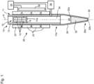
- a pipetting device according to the invention is generally designated 10.
- This comprises a pipetting channel 11, comprising a cylinder 12, which extends along a channel path K designed as a straight channel axis.
- a pipetting piston or piston for short 14 is movably received along the channel path K.
- the piston 14 comprises two end caps 16 (for reasons of clarity only the lower one is shown in the Figures 1 to 3c provided with reference symbols), between which a plurality of permanent magnets 18 (in the present example three permanent magnets 18) are accommodated.
- the permanent magnets 18 are polarized along the channel axis K in order to achieve a magnetic field with a sharp selectivity along the channel path K and are arranged in pairs with poles of the same name facing one another. This arrangement results in a magnetic field emanating from the piston 14 which is largely uniform around the channel axis K, i.e.
- the end caps 16 are preferably made of low-friction material comprising graphite or mica, as is known, for example, from commercially available caps from Airpot Corporation in Norwalk, Connecticut (US).
- the pipetting channel 11 preferably comprises a cylinder 12 made of glass, so that when the piston 14 moves along the channel axis K, the material comprising graphite or mica slides along a glass surface with extremely low friction.
- the piston 14 thus forms a rotor of a linear motor 20, the stator of which is formed by coils 22 surrounding the pipetting channel 11 (here only four coils are shown as an example).
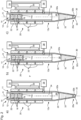
- Figures 1 to 3c merely show a roughly schematic longitudinal sectional view of a pipetting device 10 according to the invention, which is in no way to be understood to scale.
- a plurality of components is represented by any number of components, such as three permanent magnets 18 and four coils 22.
- both the number of permanent magnets 18 and the number of coils 22 can be larger or smaller than the number shown.
- the linear motor 20, or more precisely its coils 22, are controlled via a control device 24, which is connected to the coils 22 for signal transmission.
- the transmission of electrical current to energize the coils and thus to generate a magnetic field through them is also considered a signal.
- a pipette tip 26 is detachably attached in a manner known per se to the dosing-side end 12a of the cylinder 12.
- the connection of the pipette tip 26 to the dosing-side longitudinal end 12a of the cylinder 12 is also only shown in a rough schematic manner.
- the pipetting tip 26 defines a pipetting space or receiving space 28 in its interior, which is accessible at the longitudinal end 26a remote from the coupling exclusively through a pipetting opening 30.
- the pipetting tip 26 extends the pipetting channel 11 during its coupling to the cylinder 12 up to the pipetting opening 30.
- the working gas 34 is arranged between the piston 14 and a dosing liquid 32 even when the pipetting tip 26 is completely empty, since the pipetting tip 26 is immersed in a corresponding dosing liquid supply for aspiration of dosing liquid 32, so that in this state a meniscus of the dosing liquid 32 is present at least at the pipetting opening 30.
- the working gas 34 is permanently located completely between the piston 14 and a dosing liquid 32 and separates them from one another.
- the working gas 34 is located between a dosing-side end surface 14a of the piston 14, which in the present example is formed by an end surface of the end cap 16 pointing in the axial direction - relative to the channel path K - towards the dosing opening 30, and a meniscus 32a of the dosing liquid 32, which is further away from the pipetting opening and is held in the pipetting chamber 28 as a liquid column.
- a pressure sensor 38 can detect the pressure inside the pipetting channel 11, which also includes the pressure-communicating receiving space 28, the pressure of the working gas 34 between the dosing liquid 32 and the dosing-side end surface 14a of the piston 14, and transmit it to the control device 24 via a signal line.
- the pressure sensor 38 or pressure signals supplied by it, which represent the pressure of the working gas 34, can be used to control the pipetting device 10 in conventional quasi-synchronous pipetting operation, both for aspiration and for dispensing dosing liquid 32.
- the position sensor arrangement 39 for detecting the piston position is provided on the pipetting channel 11 and is connected to the control device 24 for signal transmission.
- the control device 24 supplies current to the coils 22 in such a way that the pipetting piston 14 is moved in the sense of generating a (first) negative pressure in the working gas 34, i.e. away from the pipetting opening 30.
- This negative pressure is not generated in a pulse-like manner, but with piston accelerations and speeds, which ensure a quasi-synchronous displacement of the amount of dosing liquid 32 received in the receiving space 28.
- the dosing liquid quantity 32 provided in the pipetting device 10, more precisely in the receiving space 28 of the pipetting tip 26, is guided along the channel axis K away from the pipetting opening 30 into the pipetting device 10, more precisely into the pipetting tip 26.
- the dosing liquid 32 provided is limited towards the pipetting piston 14 by a meniscus 32a that is further away from the pipetting opening 30 and is limited towards the pipetting opening 30 by a meniscus 32b that is closer to the pipetting opening.
- the gas volume 35 immediately before triggering the pulse-like dispensing overpressure pulse is preferably 4 to 10 ⁇ l, particularly preferably 4 to 6 ⁇ l.
- the meniscus 32b By moving the meniscus 32b closer to the pipette opening and therefore releasing the subsequent dosing drop 36 away from the pipette opening 30, the meniscus 32b, which after aspiration has an undefined shape, in particular an undefined curvature, at the pipette opening 30, acquires a more defined shape.
- the shape of the meniscus 32b closer to the pipette opening is not completely defined, its shape varies only slightly from a shape that would normally be expected.
- the shape of the meniscus 32b closer to the pipette opening depends, for example, on the surface tension of the dosing liquid 32, on its density, on its viscosity and on the wettability of the wall of the pipette tip 26.
- control device 24 can then drive the coils 22 to move the pipetting piston 14 in the sense of an increase in pressure in the working gas 34, ie move the pipetting piston 14 in the direction of the pipetting opening 30.
- the dosing liquid 32 provided in the pipetting tip 26 is moved back in the direction of the pipetting opening 30, but not beyond it.
- the gas volume 35 between the pipetting opening 30 and the meniscus 32b closer to the pipetting opening is thereby reduced or even disappears completely.
- This change in the working gas pressure also does not occur in a pulse-like manner, but in accordance with conventional, quasi-synchronous operation.
- control device 24 can again drive the coils 22 to move the pipetting piston 14 in the sense of reducing the pressure of the working gas 34, ie in an aspiration direction away from the pipetting opening 30, whereby a gas volume 35 is again formed and/or increased between the pipetting opening 30 and the meniscus 32b of the dosing liquid 32 closer to the pipetting opening. This also takes place in conventional quasi-synchronous pipetting operation.
- the Figure 3a represents the pipetting device 10 of Figure 2c on a separate figure sheet in order to better compare the different states of the pipetting device 10 immediately before and during the generation of a pressure pulse.
- the central point of the inventive idea of the present application is a whip-like movement of the piston 14. This whip-like movement is expressed in several different forms.
- the piston 14 can be moved with enormous movement dynamics along the channel axis K. To dispense a small amount of liquid, approximately 500 nl of the dosing liquid 32, the piston 14 is initially accelerated and moved quickly in the sense of generating a pressure increase in the working gas 34 (here: dispensing direction) towards the dosing opening 30.
- the control device 24 controls the coils 22 of the linear motor 20 in accordance with a detection result of the position sensor arrangement 39 in such a way that the piston 14 generates a pressure pulse in the working gas 34 by a pipetting piston target position curve specified in a data memory of the control device 24.
- the piston 14 executes such a large stroke P that the dosing-side end surface 14a of the piston 14 along the stroke P is a multiple, approximately 40 times, of the predetermined individual dosing volume 36 (see Figure 3c )
- the piston is then in the position Figure 3b shown position at the bottom dead center of its movement in the dispensing direction, whereupon the piston 14 is driven to an opposite movement in the aspiration direction, i.e. in the sense of a reduction in the pressure of the working gas 34 (see arrow G).
- the movement of the piston 14 is controlled in accordance with a detection result of the position sensor arrangement 39 such that the piston 14 is driven to move according to a pipetting piston target position curve predetermined in a data memory of the control device 24.
- the initial pulse-like or whip-like movement of the piston 14 in the dispensing direction lasts less than 10 ms in the present example.
- the piston 14 reaches its bottom dead center, usually no part of the dosing liquid 32 has yet separated from the pipette tip 26.
- the meniscus 32b closer to the pipette opening is shown in a shape that prepares for drop dispensing.
- the shape of the meniscus 32b is chosen merely for illustration purposes to make it clear that a drop of dosing liquid 36 (see Fig. 3c ) is imminent.
- the meniscus 32a further away from the pipetting opening is shown as concavely curved in order to illustrate the effect of the overpressure pulse on the dosing liquid 32.
- the piston is moved in the dispensing direction at a maximum speed of approximately 10,000 ⁇ l/s and is accelerated and decelerated again with an acceleration of up to 8 x 10 6 ⁇ l/s 2 .
- the maximum speed only occurs for a short time. This means that in the case mentioned, in which its dosing-side end surface 14a covers a volume of approximately 40 times the individual dosing volume 36, i.e. approximately 20 ⁇ l, during the dispensing movement, the piston 14 requires approximately 6 to 8 ms for this dispensing movement.
- the dosing liquid 32 is too slow to follow this piston movement. Instead, a pressure pulse is transmitted from the piston 14 via the working gas 34 to the dosing liquid 32 in the pipette tip 26.
- the piston 14 is now accelerated back in the aspiration direction as quickly as possible, the movement stroke G in the aspiration direction in the present case being smaller than the stroke P of the movement in the dispensing direction, such that the end piston surface 14a, during the movement in the aspiration direction, sweeps over an aspiration volume which is smaller than the swept dispensing volume by the individual dosing volume 36.
- the aspiration volume can also be as large as the dispensing volume.
- an aspiration volume reduced by the individual dosing volume 36 has the advantage that the position of the meniscus closest to the pipette opening does not change after pipetting, which is particularly advantageous in aliquoting mode.
- the movement in the aspiration direction as part of the pulse-like dispensing also takes place at the maximum speed mentioned, so that this movement also takes about 6 to 8 ms.
- additional dwell times at the bottom dead center which can arise from overcoming the static friction limit, and taking into account any movement overshoots of the piston 14 around its target position, the entire piston movement takes place until the end position is reached, as shown in Figure 3c shown, in about 14 to 30 ms.
- a defined individual dosing volume 36 in the form of a drop spun away from the pipetting opening 30.
- This drop moves along the extended imaginary channel path K to a dosing target placed under the pipetting opening 30, such as a container or a well.
- the meniscus 32b closer to the pipetting opening can continue to oscillate for a short time after the dosing liquid drop 36 has been spun off.
- the pipetting tip 26 can have a nominal pipetting chamber volume that significantly exceeds the individual dosing volume, approximately 200 - 400 ⁇ l, preferably 300 ⁇ l.
- the pressure increase pulse of the piston movement in the dispensing direction forms the steep rising edge of a pressure pulse. Its steep falling edge is formed by the pressure reduction pulse of the piston movement in the aspiration direction. The faster the individual piston movement takes place, the steeper the edge of the pressure change pulse associated with it.
- the two pressure change pulses acting in opposite directions can thus define a "hard" pressure pulse with steep edges.
- the piston movement is controlled by the control device 24 by appropriately applying a voltage to the coils 22 such that the position of the pipetting piston 14 follows a predetermined pipetting piston target position curve during the pressure pulse.
- the pipetting piston 14 can be moved to a defined end position at the end of the dispensing process.
- the dispensing process presented here is independent of the size of the selected pipette tip 26.
- the same piston movement described above would lead to exactly the same result even with a significantly smaller pipette tip of approximately a nominal pipetting chamber volume of 50 ⁇ l, provided that the same working gas and the same dosing liquid are still used with unchanged dispensing parameters.
- the present pipetting device according to the invention and the pulse-like dispensing method according to the invention are therefore ideally suited for aliquoting liquids from even large supplies of dosing liquid 32 held in pipetting tips 26. Even over many aliquoting cycles, the dispensing behavior of the pipetting device 10 does not change under otherwise identical conditions.
- the dispensing behavior of the pipetting device 10 according to the invention is therefore also independent of the filling level of a pipetting tip 26 coupled to the cylinder 12, as long as it is sufficiently filled for pulse-like dispensing.
- the piston movement may not follow the control signal that causes the movement completely exactly.
- the piston may tend to overshoot around the target position.
- the control signals that cause the movement which are a reflection of a target movement, should therefore be decisive.
- an impulse-like dispensation can also be initiated from the state according to Figure 1 can take place, ie without prior formation of the gas volume 35 near the pipette opening.
- Figure 4 is roughly schematically and merely as an example a temporal progression 42 of the movement of the piston 14 (dashed line) is shown schematically, as it occurs during a dispensing process of the Figures 3a to 3c could be present.
- the abscissa of the representation of Figure 4 shows the time in milliseconds, with a grid of 10 ms each.
- the ordinate shows the volume in microliters, whereby with respect to the position-time curve 42 of the piston 14, the volume of the ordinate axis indicates the volume swept by the dosing-side end surface 14a of the piston 14.
- the locations of the so-called "halfway point" of the piston 14 between its starting position at 0 ⁇ l and its reversal point of the direction of movement at approximately -22.5 ⁇ l are designated 46 and 48.
- the halfway point is therefore approximately -11.25 ⁇ l.
- the temporal integral of the location-time curve of the piston 14 - approximately represented by the location-time curve of the dosing-side piston surface 14a as a reference point of the piston 14 - between the passage through the location of the halfway width during the movement in the dispensing direction and the renewed passage through this location during its movement in the aspiration direction is a measure of the individual dosing volume 36 actually dispensed in a pulse-like manner with the piston movement.
- An area formed by this integral is shown as area 50 in Figure 4 shown hatched.
- the relationship between the surface area of the surface 50 and the actually pipetted individual dosing volume 36 can be easily determined empirically for different liquid classes and stored in a data memory of the pipetting device 10.
- control structure 52 is shown in rough schematic form, as it can be used in the control device 24.
- the control structure 52 is a cascaded control structure with an outer control loop 56 and an inner control loop 58.
- a pipetting piston target position curve 60 is stored in a data memory 59 of the control device 24, which contains target values of the pressure in the working gas as a function of time for a pulse-like dispensing process for dispensing a predetermined volume of liquid.
- a plurality of pipetting piston target position profiles can be stored in the data memory 59 of the control device 24, namely in a multi-dimensional arrangement for different liquid classes and within the different liquid classes for different dosing liquid quantities.
- the control device 24 selects the predetermined pipetting piston target position curve 60 applicable to the indicated dosing liquid quantity for the liquid class also indicated by manual data input or automated data transfer and supplies this to an external operator 66.
- This first operator 66 is also supplied with the detection result of the position sensor arrangement 39 and thus the actual position of the pipetting piston 14. The first operator 66 thus outputs a difference value of the pipetting piston position, which is a measure of the difference between the applicable pipetting piston target position and the detected pipetting piston actual position for each detection time.
- the predetermined pipetting piston target position curve 60 is also stored in the data memory 59 of the control device 24 for advantageously rapid pre-control of the movement of the pipetting piston 14.
- the value of the pipetting piston position resulting from the respective detection time according to the predetermined is also fed to the first operator 66 by means of a feedforward control known per se.
- a value representing the difference between the pipetting piston target position and the pipetting piston actual position is fed from the first operator 66 to the first, external controller 70, which is advantageously designed as a PID controller. Its transfer function determines a target value for the current flowing in the coils 22 of the motion drive 20 at the time of detection from the difference value representing the difference between the target and actual position of the pipetting piston 14. This current target value is fed to a second operator 72. The second operator 72 is also fed the current actual value at the time of detection, which can be easily determined from the coils 22 in a manner known per se.
- the second operator 72 thus determines a value representing the difference between the current setpoint and the current actual value at the time of detection and supplies this to the second internal controller 74.
- the second or internal controller 74 advantageously has a PI control behavior.
- a predetermined coil target current value curve 76 is stored in the data memory of the control device 24, which results from the predetermined pipetting piston target position curve 60.
- the predetermined coil target current value applicable for the respective detection time is fed to the second operator 72 by means of a known feedforward control from the predetermined coil target current value curve 76 in order to obtain the fastest possible control of the movement of the pipetting piston 14 such that the movement of the pipetting piston 14 corresponds as precisely as possible to the pipetting piston target position curve 60 selected for the respective pipetting process.
- the transfer function of the second or inner controller 74 determines the difference between the current setpoint and the The input value representing the actual current value at the time of detection is a coil target voltage value at the time of detection, which is applied to the coils 22.
- the control loop structure 52 can be separate for each phase of the coils 22.
- a predetermined coil target voltage curve 78 is stored in the data memory of the control device 24, which results from the predetermined pipetting piston target position curve 60 and/or the predetermined coil target current value curve 76.
- a third operator 80 is shown to carry out the pre-control of the coil voltage by means of the predetermined coil target voltage curve.
- the pipetting piston 14 can be moved so precisely in the range of a few milliseconds by applying an operating voltage to the coils 22 on the basis of the detected pipetting piston position and the detected coil current that the pipetting piston position essentially follows a predetermined pipetting piston position curve.
- the ordinate of the graphs of Figures 6 to 8 indicates a piston stroke in millimeters.
- the starting position of the pipetting piston 14 has the coordinate 0 mm.
- Negative ordinate values indicate a displacement of the pipetting piston starting from the starting position of the dispensing process, which is 0 mm, in the dispensing direction. Accordingly, positive ordinate values indicate a position of the pipetting piston on the aspiration side in relation to the starting position.
- Figure 6 shows the position curves 61 and 71 for a dosing liquid volume of 500 nl to be dispensed in a pulsed manner.
- the pipetting piston 14 begins to move in the dispensing direction toward the pipetting opening 30.
- the pressure of the working gas 34 in the receiving chamber 28 will therefore increase.
- the pipetting piston 14 reaches its position of greatest proximity to the pipetting opening 30, characterized by the greatest value in terms of magnitude on the dispensing side of the starting position of the piston 14.
- a reversal of movement of the pipetting piston 14 immediately begins, which is then moved in the aspiration direction, recognizable by the negative values becoming smaller in terms of magnitude.
- the pipetting piston 14 returns to its starting position. However, it is moved beyond this in the aspiration direction until it reaches its position of maximum distance from the pipetting opening 30 in the range between 1.03 and 1.06 ms. From then on, the pipetting piston is moved back in the dispensing direction to the starting position, which it reaches at about 1.12 ms, i.e. about 6.1 to 6.2 ms after the start of the piston movement as part of the dispensing process.
- the drop of dosing liquid is only released after reaching the position of maximum proximity to the pipetting opening 30. This also applies to the dispensing of the Figures 7 and 8 .
- the Figure 7 shows the pipetting piston target position curve 63 and the pipetting piston actual position curve 73 for a dosing liquid volume of 1 ⁇ l to be dispensed in a pulsed manner.
- the piston movement for this dispensing process lasts about 9 ms, namely from about 5 ms to about 14 ms.
- the pipetting piston 14 is initially brought closer to the pipetting opening 30 for the dispensing, in sections even at a constant speed.
- the phase of constant piston speed lasts from about 7.8 to 10.2 ms in the example shown. Shortly after the end of the constant speed phase, the pipetting piston 14 reaches its position of greatest proximity to the pipetting opening 30.
- the pipetting piston 14 returns to its starting position and at about 13.2 ms it reaches its position of maximum distance from the pipetting opening.
- the piston movement ends at about 14 ms.
- the movement of the pipetting piston 14 begins at about 5 ms with an approach to the pipetting opening 30.
- the piston 14 is moved at a constant speed in the dispensing direction from about 7 ms.
- the movement at a constant approach speed to the pipetting opening 30 ends at about 17 ms.
- the piston 14 is as close as possible to the pipetting opening 30.
- the pipetting piston 14 no longer reaches its starting position with the large amount of liquid dosed in pulses. At about 18.8 ms, the pipetting piston 14 reaches its position of greatest distance from the pipetting opening 30 and at about 19.5 ms, i.e. approximately 14.5 ms after the start of the movement of the pipetting piston, this movement is terminated again.
- the pipetting piston movement can generally have phases of constant piston speed. Preferably, these are at least not shorter, and preferably even longer, during the initial, first piston movement in the dispensing direction than in the subsequent phase of a piston movement in the aspiration direction.
- the movement impulse of the pipetting piston may become longer, but surprisingly the piston stroke covered in the first dispensing movement becomes smaller.
- Fig. 8 For the dispensed 1.5 ⁇ l, the piston stroke is only about 0.7 mm in the dispensing direction, while for the dispensed quantity of 1 ⁇ l according to Fig. 7 about 0.95 mm and at the amount of 0.5 ⁇ l of Fig. 6 was about 1 mm.
- the piston stroke from the position of maximum distance from the pipetting opening to the end position at the end of the piston movement of a dispensing process is approximately the same regardless of the dosing quantity. At least the piston positions of maximum distance from the pipetting opening and the end position differ less in magnitude for different pulse-dispensed dosing volumes or quantities than the piston positions of the start position and the maximum approach to the pipetting opening differ.
- the repeatability of dispensed dosing liquid volumes that can be achieved with the present control method is in the range of less than 3%.
Landscapes
- Health & Medical Sciences (AREA)
- Chemical & Material Sciences (AREA)
- Clinical Laboratory Science (AREA)
- Chemical Kinetics & Catalysis (AREA)
- Engineering & Computer Science (AREA)
- Human Computer Interaction (AREA)
- Analytical Chemistry (AREA)
- Life Sciences & Earth Sciences (AREA)
- Physics & Mathematics (AREA)
- Biochemistry (AREA)
- General Health & Medical Sciences (AREA)
- General Physics & Mathematics (AREA)
- Immunology (AREA)
- Pathology (AREA)
- Sampling And Sample Adjustment (AREA)
- Feeding, Discharge, Calcimining, Fusing, And Gas-Generation Devices (AREA)
- Automatic Analysis And Handling Materials Therefor (AREA)
- Devices For Use In Laboratory Experiments (AREA)
Applications Claiming Priority (2)
| Application Number | Priority Date | Filing Date | Title |
|---|---|---|---|
| DE102018211497.8A DE102018211497A1 (de) | 2018-07-11 | 2018-07-11 | Pipettiervorrichtung zur impulsartigen Pipettierung mit einer basierend auf einer Erfassung des Arbeitsgasdrucks geregelten Pipettierkolbenbewegung |
| PCT/EP2019/068417 WO2020011787A1 (de) | 2018-07-11 | 2019-07-09 | Pipettiervorrichtung zur impulsartigen pipettierung mit einer basierend auf einer erfassung der kolbenposition geregelten pipettierkolbenbewegung |
Publications (2)
| Publication Number | Publication Date |
|---|---|
| EP3820614A1 EP3820614A1 (de) | 2021-05-19 |
| EP3820614B1 true EP3820614B1 (de) | 2024-11-13 |
Family
ID=67514561
Family Applications (1)
| Application Number | Title | Priority Date | Filing Date |
|---|---|---|---|
| EP19748709.3A Active EP3820614B1 (de) | 2018-07-11 | 2019-07-09 | Pipettiervorrichtung zur impulsartigen pipettierung mit einer basierend auf einer erfassung der kolbenposition geregelten pipettierkolbenbewegung |
Country Status (6)
| Country | Link |
|---|---|
| US (1) | US11911757B2 (https=) |
| EP (1) | EP3820614B1 (https=) |
| JP (1) | JP7455801B2 (https=) |
| CN (1) | CN112423886B (https=) |
| DE (1) | DE102018211497A1 (https=) |
| WO (1) | WO2020011787A1 (https=) |
Families Citing this family (7)
| Publication number | Priority date | Publication date | Assignee | Title |
|---|---|---|---|---|
| US11124406B1 (en) * | 2014-07-13 | 2021-09-21 | Sestra Systems, Inc. | System and method for piston detection in a metering mechanism for use with beverage dispensing system |
| DE102018125196A1 (de) * | 2018-10-11 | 2020-04-16 | Hamilton Bonaduz Ag | Vorrichtung und Verfahren zur Qualitätsbestimmung einer impulsartigen Flüssigkeitsdispensation nach dem Air-Displacement-Prinzip |
| DE102019126731A1 (de) * | 2019-10-02 | 2021-04-08 | Hamilton Bonaduz Ag | Vorrichtung und Verfahren zum exakten flüssigkeitsklassen-unabhängigen Pipettieren |
| DE102020104422A1 (de) * | 2020-02-19 | 2021-08-19 | Hamilton Bonaduz Ag | Verfahren zur Zuordnung einer Pipettierspitze zu einer Pipettierspitzenklasse aufgrund ihres pneumatischen Verhaltens |
| WO2021241357A1 (ja) * | 2020-05-29 | 2021-12-02 | 株式会社日立ハイテク | 自動分析装置の制御方法 |
| US11559823B2 (en) * | 2020-09-18 | 2023-01-24 | Asmpt Singapore Pte. Ltd. | Volumetric measurement and regulation device incorporated in a time-pressure dispenser |
| CN116832891A (zh) * | 2023-08-10 | 2023-10-03 | 上海镁伽智能科技有限公司 | 用于移液装置的变距方法、变距控制装置及移液设备 |
Family Cites Families (11)
| Publication number | Priority date | Publication date | Assignee | Title |
|---|---|---|---|---|
| JP3750460B2 (ja) | 2000-02-18 | 2006-03-01 | 日立工機株式会社 | 分注装置及び分注方法 |
| JP2006132984A (ja) * | 2004-11-02 | 2006-05-25 | Sumitomo Heavy Ind Ltd | 放射性液体の分注方法及び分注装置 |
| JP2008197037A (ja) * | 2007-02-15 | 2008-08-28 | Yaskawa Electric Corp | 分注装置およびそのコントローラと分注方法 |
| WO2010060448A1 (de) * | 2008-11-28 | 2010-06-03 | Hamilton Bonaduz Ag | Für die dosierung von sehr kleinen dosiervolumina geeignete dosiereinrichtung und dosierverfahren |
| DE102010000690A1 (de) * | 2010-01-05 | 2011-07-07 | Hamilton Bonaduz Ag | Dosiervorrichtung und Dosierverfahren |
| WO2013094373A1 (ja) | 2011-12-22 | 2013-06-27 | 三洋電機株式会社 | 分注装置 |
| DE102012214677A1 (de) * | 2012-08-17 | 2014-02-20 | Hamilton Bonaduz Ag | Pipette mit elektromotorisch angetriebenem Kolben und Magnetfeldabschirmung |
| DE102015214566A1 (de) * | 2015-07-30 | 2017-02-02 | Hamilton Bonaduz Ag | Pipettiervorrichtung zur Pipettierung kleiner Flüssigkeitsvolumina |
| DE102016225209A1 (de) * | 2016-12-15 | 2018-06-21 | Hamilton Bonaduz Ag | Pipettiervorrichtung zur verbesserten impulsartigen Flüssigkeitspipettierung |
| DE102017201114A1 (de) * | 2017-01-24 | 2018-07-26 | Hamilton Bonaduz Ag | Pipettiervorrichtung zur impulsartigen Pipettierung mit einer basierend auf einer Erfassung des Arbeitsgasdrucks geregelten Pipettierkolbenbewegung |
| EP3434373A1 (de) * | 2017-07-27 | 2019-01-30 | Eppendorf AG | Pipettiervorrichtung mit funktionsprüfung und verfahren zur funktionsprüfung einer pipettiervorrichtung |
-
2018
- 2018-07-11 DE DE102018211497.8A patent/DE102018211497A1/de not_active Withdrawn
-
2019
- 2019-07-09 JP JP2021500610A patent/JP7455801B2/ja active Active
- 2019-07-09 US US17/258,488 patent/US11911757B2/en active Active
- 2019-07-09 EP EP19748709.3A patent/EP3820614B1/de active Active
- 2019-07-09 WO PCT/EP2019/068417 patent/WO2020011787A1/de not_active Ceased
- 2019-07-09 CN CN201980046583.2A patent/CN112423886B/zh active Active
Also Published As
| Publication number | Publication date |
|---|---|
| JP7455801B2 (ja) | 2024-03-26 |
| CN112423886A (zh) | 2021-02-26 |
| DE102018211497A1 (de) | 2020-01-16 |
| US20210154659A1 (en) | 2021-05-27 |
| JP2021524376A (ja) | 2021-09-13 |
| WO2020011787A1 (de) | 2020-01-16 |
| CN112423886B (zh) | 2023-03-07 |
| US11911757B2 (en) | 2024-02-27 |
| EP3820614A1 (de) | 2021-05-19 |
Similar Documents
| Publication | Publication Date | Title |
|---|---|---|
| EP3573758B1 (de) | Pipettiervorrichtung zur impulsartigen pipettierung mit einer basierend auf einer erfassung des arbeitsgasdrucks geregelten pipettierkolbenbewegung | |
| EP3820614B1 (de) | Pipettiervorrichtung zur impulsartigen pipettierung mit einer basierend auf einer erfassung der kolbenposition geregelten pipettierkolbenbewegung | |
| EP3328545B1 (de) | Pipettiervorrichtung zur pipettierung kleiner flüssigkeitsvolumina | |
| EP3554706B1 (de) | Pipettiervorrichtung zur verbesserten impulsartigen flüssigkeitspipettierung | |
| EP2165770B1 (de) | Austragvorrichtung | |
| EP2521620B1 (de) | Pipette | |
| EP1150105B1 (de) | Gaspolster-Mikrodosiersystem | |
| EP3434373A1 (de) | Pipettiervorrichtung mit funktionsprüfung und verfahren zur funktionsprüfung einer pipettiervorrichtung | |
| EP3863765A1 (de) | Vorrichtung und verfahren zur qualitätsbestimmung einer impulsartigen flüssigkeitsdispensation nach dem air-displacement-prinzip | |
| EP4021640B1 (de) | Vorrichtung und verfahren zum exakten flüssigkeitsklassen-unabhängigen pipettieren | |
| EP4164798B1 (de) | Pipettiervorrichtung mit durch gasschall ausgelöster dispensation von flüssigkeitsmengen im bereich von vorzugsweise 10 bis 500 nl | |
| EP3450020B1 (de) | Mikrodosiereinrichtung zur dosierung von kleinsten fluidproben |
Legal Events
| Date | Code | Title | Description |
|---|---|---|---|
| STAA | Information on the status of an ep patent application or granted ep patent |
Free format text: STATUS: UNKNOWN |
|
| STAA | Information on the status of an ep patent application or granted ep patent |
Free format text: STATUS: THE INTERNATIONAL PUBLICATION HAS BEEN MADE |
|
| PUAI | Public reference made under article 153(3) epc to a published international application that has entered the european phase |
Free format text: ORIGINAL CODE: 0009012 |
|
| STAA | Information on the status of an ep patent application or granted ep patent |
Free format text: STATUS: REQUEST FOR EXAMINATION WAS MADE |
|
| 17P | Request for examination filed |
Effective date: 20210209 |
|
| AK | Designated contracting states |
Kind code of ref document: A1 Designated state(s): AL AT BE BG CH CY CZ DE DK EE ES FI FR GB GR HR HU IE IS IT LI LT LU LV MC MK MT NL NO PL PT RO RS SE SI SK SM TR |
|
| RIN1 | Information on inventor provided before grant (corrected) |
Inventor name: ROMER, HANSPETER Inventor name: ETTINGER, RETO Inventor name: GYSEL, FRIDOLIN Inventor name: RAST, JUERG Inventor name: HILTI, JONAS |
|
| DAV | Request for validation of the european patent (deleted) | ||
| DAX | Request for extension of the european patent (deleted) | ||
| GRAP | Despatch of communication of intention to grant a patent |
Free format text: ORIGINAL CODE: EPIDOSNIGR1 |
|
| GRAP | Despatch of communication of intention to grant a patent |
Free format text: ORIGINAL CODE: EPIDOSNIGR1 |
|
| STAA | Information on the status of an ep patent application or granted ep patent |
Free format text: STATUS: GRANT OF PATENT IS INTENDED |
|
| RIC1 | Information provided on ipc code assigned before grant |
Ipc: G01N 35/10 20060101ALI20240527BHEP Ipc: B01L 3/02 20060101AFI20240527BHEP |
|
| INTG | Intention to grant announced |
Effective date: 20240614 |
|
| GRAS | Grant fee paid |
Free format text: ORIGINAL CODE: EPIDOSNIGR3 |
|
| GRAA | (expected) grant |
Free format text: ORIGINAL CODE: 0009210 |
|
| STAA | Information on the status of an ep patent application or granted ep patent |
Free format text: STATUS: THE PATENT HAS BEEN GRANTED |
|
| AK | Designated contracting states |
Kind code of ref document: B1 Designated state(s): AL AT BE BG CH CY CZ DE DK EE ES FI FR GB GR HR HU IE IS IT LI LT LU LV MC MK MT NL NO PL PT RO RS SE SI SK SM TR |
|
| REG | Reference to a national code |
Ref country code: GB Ref legal event code: FG4D Free format text: NOT ENGLISH |
|
| REG | Reference to a national code |
Ref country code: CH Ref legal event code: EP |
|
| REG | Reference to a national code |
Ref country code: DE Ref legal event code: R096 Ref document number: 502019012485 Country of ref document: DE |
|
| REG | Reference to a national code |
Ref country code: IE Ref legal event code: FG4D Free format text: LANGUAGE OF EP DOCUMENT: GERMAN |
|
| REG | Reference to a national code |
Ref country code: LT Ref legal event code: MG9D |
|
| REG | Reference to a national code |
Ref country code: NL Ref legal event code: MP Effective date: 20241113 |
|
| PG25 | Lapsed in a contracting state [announced via postgrant information from national office to epo] |
Ref country code: IS Free format text: LAPSE BECAUSE OF FAILURE TO SUBMIT A TRANSLATION OF THE DESCRIPTION OR TO PAY THE FEE WITHIN THE PRESCRIBED TIME-LIMIT Effective date: 20250313 Ref country code: PT Free format text: LAPSE BECAUSE OF FAILURE TO SUBMIT A TRANSLATION OF THE DESCRIPTION OR TO PAY THE FEE WITHIN THE PRESCRIBED TIME-LIMIT Effective date: 20250313 Ref country code: HR Free format text: LAPSE BECAUSE OF FAILURE TO SUBMIT A TRANSLATION OF THE DESCRIPTION OR TO PAY THE FEE WITHIN THE PRESCRIBED TIME-LIMIT Effective date: 20241113 |
|
| PG25 | Lapsed in a contracting state [announced via postgrant information from national office to epo] |
Ref country code: FI Free format text: LAPSE BECAUSE OF FAILURE TO SUBMIT A TRANSLATION OF THE DESCRIPTION OR TO PAY THE FEE WITHIN THE PRESCRIBED TIME-LIMIT Effective date: 20241113 Ref country code: NL Free format text: LAPSE BECAUSE OF FAILURE TO SUBMIT A TRANSLATION OF THE DESCRIPTION OR TO PAY THE FEE WITHIN THE PRESCRIBED TIME-LIMIT Effective date: 20241113 |
|
| PG25 | Lapsed in a contracting state [announced via postgrant information from national office to epo] |
Ref country code: BG Free format text: LAPSE BECAUSE OF FAILURE TO SUBMIT A TRANSLATION OF THE DESCRIPTION OR TO PAY THE FEE WITHIN THE PRESCRIBED TIME-LIMIT Effective date: 20241113 |
|
| PG25 | Lapsed in a contracting state [announced via postgrant information from national office to epo] |
Ref country code: ES Free format text: LAPSE BECAUSE OF FAILURE TO SUBMIT A TRANSLATION OF THE DESCRIPTION OR TO PAY THE FEE WITHIN THE PRESCRIBED TIME-LIMIT Effective date: 20241113 |
|
| PG25 | Lapsed in a contracting state [announced via postgrant information from national office to epo] |
Ref country code: NO Free format text: LAPSE BECAUSE OF FAILURE TO SUBMIT A TRANSLATION OF THE DESCRIPTION OR TO PAY THE FEE WITHIN THE PRESCRIBED TIME-LIMIT Effective date: 20250213 |
|
| PG25 | Lapsed in a contracting state [announced via postgrant information from national office to epo] |
Ref country code: GR Free format text: LAPSE BECAUSE OF FAILURE TO SUBMIT A TRANSLATION OF THE DESCRIPTION OR TO PAY THE FEE WITHIN THE PRESCRIBED TIME-LIMIT Effective date: 20250214 Ref country code: LV Free format text: LAPSE BECAUSE OF FAILURE TO SUBMIT A TRANSLATION OF THE DESCRIPTION OR TO PAY THE FEE WITHIN THE PRESCRIBED TIME-LIMIT Effective date: 20241113 |
|
| PG25 | Lapsed in a contracting state [announced via postgrant information from national office to epo] |
Ref country code: PL Free format text: LAPSE BECAUSE OF FAILURE TO SUBMIT A TRANSLATION OF THE DESCRIPTION OR TO PAY THE FEE WITHIN THE PRESCRIBED TIME-LIMIT Effective date: 20241113 |
|
| PG25 | Lapsed in a contracting state [announced via postgrant information from national office to epo] |
Ref country code: RS Free format text: LAPSE BECAUSE OF FAILURE TO SUBMIT A TRANSLATION OF THE DESCRIPTION OR TO PAY THE FEE WITHIN THE PRESCRIBED TIME-LIMIT Effective date: 20250213 |
|
| PG25 | Lapsed in a contracting state [announced via postgrant information from national office to epo] |
Ref country code: SM Free format text: LAPSE BECAUSE OF FAILURE TO SUBMIT A TRANSLATION OF THE DESCRIPTION OR TO PAY THE FEE WITHIN THE PRESCRIBED TIME-LIMIT Effective date: 20241113 |
|
| PG25 | Lapsed in a contracting state [announced via postgrant information from national office to epo] |
Ref country code: DK Free format text: LAPSE BECAUSE OF FAILURE TO SUBMIT A TRANSLATION OF THE DESCRIPTION OR TO PAY THE FEE WITHIN THE PRESCRIBED TIME-LIMIT Effective date: 20241113 |
|
| PGFP | Annual fee paid to national office [announced via postgrant information from national office to epo] |
Ref country code: GB Payment date: 20250619 Year of fee payment: 7 |
|
| PG25 | Lapsed in a contracting state [announced via postgrant information from national office to epo] |
Ref country code: EE Free format text: LAPSE BECAUSE OF FAILURE TO SUBMIT A TRANSLATION OF THE DESCRIPTION OR TO PAY THE FEE WITHIN THE PRESCRIBED TIME-LIMIT Effective date: 20241113 |
|
| PG25 | Lapsed in a contracting state [announced via postgrant information from national office to epo] |
Ref country code: RO Free format text: LAPSE BECAUSE OF FAILURE TO SUBMIT A TRANSLATION OF THE DESCRIPTION OR TO PAY THE FEE WITHIN THE PRESCRIBED TIME-LIMIT Effective date: 20241113 |
|
| PG25 | Lapsed in a contracting state [announced via postgrant information from national office to epo] |
Ref country code: SK Free format text: LAPSE BECAUSE OF FAILURE TO SUBMIT A TRANSLATION OF THE DESCRIPTION OR TO PAY THE FEE WITHIN THE PRESCRIBED TIME-LIMIT Effective date: 20241113 |
|
| PG25 | Lapsed in a contracting state [announced via postgrant information from national office to epo] |
Ref country code: CZ Free format text: LAPSE BECAUSE OF FAILURE TO SUBMIT A TRANSLATION OF THE DESCRIPTION OR TO PAY THE FEE WITHIN THE PRESCRIBED TIME-LIMIT Effective date: 20241113 |
|
| PG25 | Lapsed in a contracting state [announced via postgrant information from national office to epo] |
Ref country code: IT Free format text: LAPSE BECAUSE OF FAILURE TO SUBMIT A TRANSLATION OF THE DESCRIPTION OR TO PAY THE FEE WITHIN THE PRESCRIBED TIME-LIMIT Effective date: 20241113 |
|
| REG | Reference to a national code |
Ref country code: DE Ref legal event code: R097 Ref document number: 502019012485 Country of ref document: DE |
|
| PG25 | Lapsed in a contracting state [announced via postgrant information from national office to epo] |
Ref country code: SE Free format text: LAPSE BECAUSE OF FAILURE TO SUBMIT A TRANSLATION OF THE DESCRIPTION OR TO PAY THE FEE WITHIN THE PRESCRIBED TIME-LIMIT Effective date: 20241113 |
|
| PLBE | No opposition filed within time limit |
Free format text: ORIGINAL CODE: 0009261 |
|
| STAA | Information on the status of an ep patent application or granted ep patent |
Free format text: STATUS: NO OPPOSITION FILED WITHIN TIME LIMIT |
|
| PGFP | Annual fee paid to national office [announced via postgrant information from national office to epo] |
Ref country code: DE Payment date: 20250620 Year of fee payment: 7 |
|
| PGFP | Annual fee paid to national office [announced via postgrant information from national office to epo] |
Ref country code: CH Payment date: 20250801 Year of fee payment: 7 |
|
| 26N | No opposition filed |
Effective date: 20250814 |
|
| PG25 | Lapsed in a contracting state [announced via postgrant information from national office to epo] |
Ref country code: LU Free format text: LAPSE BECAUSE OF NON-PAYMENT OF DUE FEES Effective date: 20250709 |
|
| REG | Reference to a national code |
Ref country code: BE Ref legal event code: MM Effective date: 20250731 |
|
| PG25 | Lapsed in a contracting state [announced via postgrant information from national office to epo] |
Ref country code: BE Free format text: LAPSE BECAUSE OF NON-PAYMENT OF DUE FEES Effective date: 20250731 |
|
| PG25 | Lapsed in a contracting state [announced via postgrant information from national office to epo] |
Ref country code: FR Free format text: LAPSE BECAUSE OF NON-PAYMENT OF DUE FEES Effective date: 20250731 |