EP3820249B1 - Seal arrangement for a cooking device - Google Patents
Seal arrangement for a cooking device Download PDFInfo
- Publication number
- EP3820249B1 EP3820249B1 EP20191944.6A EP20191944A EP3820249B1 EP 3820249 B1 EP3820249 B1 EP 3820249B1 EP 20191944 A EP20191944 A EP 20191944A EP 3820249 B1 EP3820249 B1 EP 3820249B1
- Authority
- EP
- European Patent Office
- Prior art keywords
- sealing
- ring
- sealing ring
- illumination element
- seal
- Prior art date
- Legal status (The legal status is an assumption and is not a legal conclusion. Google has not performed a legal analysis and makes no representation as to the accuracy of the status listed.)
- Active
Links
Images

Classifications
-
- A—HUMAN NECESSITIES
- A47—FURNITURE; DOMESTIC ARTICLES OR APPLIANCES; COFFEE MILLS; SPICE MILLS; SUCTION CLEANERS IN GENERAL
- A47J—KITCHEN EQUIPMENT; COFFEE MILLS; SPICE MILLS; APPARATUS FOR MAKING BEVERAGES
- A47J27/00—Cooking-vessels
- A47J27/002—Construction of cooking-vessels; Methods or processes of manufacturing specially adapted for cooking-vessels
-
- A—HUMAN NECESSITIES
- A47—FURNITURE; DOMESTIC ARTICLES OR APPLIANCES; COFFEE MILLS; SPICE MILLS; SUCTION CLEANERS IN GENERAL
- A47J—KITCHEN EQUIPMENT; COFFEE MILLS; SPICE MILLS; APPARATUS FOR MAKING BEVERAGES
- A47J37/00—Baking; Roasting; Grilling; Frying
- A47J37/06—Roasters; Grills; Sandwich grills
- A47J37/0623—Small-size cooking ovens, i.e. defining an at least partially closed cooking cavity
- A47J37/0664—Accessories
-
- A—HUMAN NECESSITIES
- A47—FURNITURE; DOMESTIC ARTICLES OR APPLIANCES; COFFEE MILLS; SPICE MILLS; SUCTION CLEANERS IN GENERAL
- A47J—KITCHEN EQUIPMENT; COFFEE MILLS; SPICE MILLS; APPARATUS FOR MAKING BEVERAGES
- A47J27/00—Cooking-vessels
- A47J27/04—Cooking-vessels for cooking food in steam; Devices for extracting fruit juice by means of steam ; Vacuum cooking vessels
-
- A—HUMAN NECESSITIES
- A47—FURNITURE; DOMESTIC ARTICLES OR APPLIANCES; COFFEE MILLS; SPICE MILLS; SUCTION CLEANERS IN GENERAL
- A47J—KITCHEN EQUIPMENT; COFFEE MILLS; SPICE MILLS; APPARATUS FOR MAKING BEVERAGES
- A47J36/00—Parts, details or accessories of cooking-vessels
-
- A—HUMAN NECESSITIES
- A47—FURNITURE; DOMESTIC ARTICLES OR APPLIANCES; COFFEE MILLS; SPICE MILLS; SUCTION CLEANERS IN GENERAL
- A47J—KITCHEN EQUIPMENT; COFFEE MILLS; SPICE MILLS; APPARATUS FOR MAKING BEVERAGES
- A47J36/00—Parts, details or accessories of cooking-vessels
- A47J36/02—Selection of specific materials, e.g. heavy bottoms with copper inlay or with insulating inlay
- A47J36/04—Selection of specific materials, e.g. heavy bottoms with copper inlay or with insulating inlay the materials being non-metallic
-
- A—HUMAN NECESSITIES
- A47—FURNITURE; DOMESTIC ARTICLES OR APPLIANCES; COFFEE MILLS; SPICE MILLS; SUCTION CLEANERS IN GENERAL
- A47J—KITCHEN EQUIPMENT; COFFEE MILLS; SPICE MILLS; APPARATUS FOR MAKING BEVERAGES
- A47J37/00—Baking; Roasting; Grilling; Frying
- A47J37/06—Roasters; Grills; Sandwich grills
- A47J37/0623—Small-size cooking ovens, i.e. defining an at least partially closed cooking cavity
-
- F—MECHANICAL ENGINEERING; LIGHTING; HEATING; WEAPONS; BLASTING
- F24—HEATING; RANGES; VENTILATING
- F24C—DOMESTIC STOVES OR RANGES ; DETAILS OF DOMESTIC STOVES OR RANGES, OF GENERAL APPLICATION
- F24C15/00—Details
-
- F—MECHANICAL ENGINEERING; LIGHTING; HEATING; WEAPONS; BLASTING
- F24—HEATING; RANGES; VENTILATING
- F24C—DOMESTIC STOVES OR RANGES ; DETAILS OF DOMESTIC STOVES OR RANGES, OF GENERAL APPLICATION
- F24C15/00—Details
- F24C15/008—Illumination for oven cavities
-
- F—MECHANICAL ENGINEERING; LIGHTING; HEATING; WEAPONS; BLASTING
- F24—HEATING; RANGES; VENTILATING
- F24C—DOMESTIC STOVES OR RANGES ; DETAILS OF DOMESTIC STOVES OR RANGES, OF GENERAL APPLICATION
- F24C15/00—Details
- F24C15/08—Foundations or supports plates; Legs or pillars; Casings; Wheels
-
- F—MECHANICAL ENGINEERING; LIGHTING; HEATING; WEAPONS; BLASTING
- F24—HEATING; RANGES; VENTILATING
- F24C—DOMESTIC STOVES OR RANGES ; DETAILS OF DOMESTIC STOVES OR RANGES, OF GENERAL APPLICATION
- F24C7/00—Stoves or ranges heated by electric energy
- F24C7/02—Stoves or ranges heated by electric energy using microwaves
-
- H—ELECTRICITY
- H05—ELECTRIC TECHNIQUES NOT OTHERWISE PROVIDED FOR
- H05B—ELECTRIC HEATING; ELECTRIC LIGHT SOURCES NOT OTHERWISE PROVIDED FOR; CIRCUIT ARRANGEMENTS FOR ELECTRIC LIGHT SOURCES, IN GENERAL
- H05B6/00—Heating by electric, magnetic or electromagnetic fields
- H05B6/64—Heating using microwaves
- H05B6/6444—Aspects relating to lighting devices in the microwave cavity
-
- H—ELECTRICITY
- H05—ELECTRIC TECHNIQUES NOT OTHERWISE PROVIDED FOR
- H05B—ELECTRIC HEATING; ELECTRIC LIGHT SOURCES NOT OTHERWISE PROVIDED FOR; CIRCUIT ARRANGEMENTS FOR ELECTRIC LIGHT SOURCES, IN GENERAL
- H05B6/00—Heating by electric, magnetic or electromagnetic fields
- H05B6/64—Heating using microwaves
- H05B6/76—Prevention of microwave leakage, e.g. door sealings
Definitions
- the invention relates to a sealing arrangement for a cooking device such as an oven, steam cooker or microwave for sealing an opening in the cooking space wall, the implementation of a lighting element used for lighting the cooking space, in particular a glass rod with an essentially circular cylindrical shape, with a housing part which is provided with a first seal is sealed against the cooking chamber wall and has a receptacle for a second seal which seals the housing part against the lighting element, with holding parts which arrange the housing part on the cooking chamber wall, the second seal being a graphite ring, within the annular space of which the lighting element can be arranged.
- the document FR 2414170 A1 discloses a sealing arrangement according to the preamble of claim 1.
- the light guide rods penetrate the cooking chamber wall through corresponding openings that have to be sealed against the passage of vapor.
- the object of the invention is to create an advantageous sealing arrangement here.
- a sealing arrangement according to the invention is provided overall with the reference number 10.
- the individual parts of the sealing arrangement are in particular from the exploded view in Figure 1 evident.
- the sealing arrangement initially comprises a housing part 11 with a circular cylindrical base body 12, which forms a circumferentially enlarged collar 13 at one end.
- the collar 13 forms an annular groove 14 which is open in the direction of the free end of the base body 12.
- the annular groove 14 receives a first seal in the form of the annular seal 15.
- the base body 12 At its end facing away from the collar 13, the base body 12 has an unspecified receptacle for a sealing ring 16.
- the base body also has fastening recesses 17 into which retaining means 18 engage in order to fasten a retaining clip 19 on the base body 12.
- the ends 20 of the retaining clip 19 are designed to be resilient.
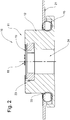
- FIG. 2 shows a sectional view of the installation situation of the sealing arrangement 10 according to FIG Figure 1 .
- a part of a cooking chamber wall 21 is shown, which has an opening 22 for the implementation of a lamp element, in particular a rod-shaped, cylindrical light guide, for example a glass rod or plastic rod.
- the sealing arrangement 13 is inserted into this opening 22, the base body 12 being mounted in the opening 22.
- the collar 13 is placed on the cooking space side against the cooking space wall 21 so that the ring seal 15 seals against the collar 13 on the one hand and against the cooking space wall 21 on the other hand. A passage of vapor between the base body 12 and the cooking chamber wall 21 is reliably avoided.
- the sectional view according to Figure 2 now shows the seal receptacle 23 is designed as a circumferentially enlarged recess compared to the annular space 24 of the base body.
- the sealing ring 16 is inserted into this seal receptacle 23. It seals on the one hand against the base body 12 and on the other hand against a light guide rod, not shown here, which penetrates the sealing ring 16 and is mounted in the annular space 24 of the base body 12.
- the housing part 11 is held by the retaining clip 19 on the cooking chamber wall 21. This is supported by an in Figure 2 In a manner not shown, the resilient elastic ends 20 of the retaining clip 19 on the outer surface of the cooking chamber wall 21 facing away from the cooking chamber. The spring restoring forces tension the collar 13 against the cooking space wall and ensure a tight fit of the ring seal 15.
- the sealing ring 16 which has a sealing effect on the light guide rod, is to be made from a suitable sealing material.
- this is Graphite.
- This graphite is matched in a suitable form to the light guide rod with regard to its coefficient of thermal expansion.
- An almost identical coefficient of thermal expansion of the light guide rod and graphite ring is preferred.
- a slightly higher coefficient of thermal expansion of the graphite ring compared to the coefficient of thermal expansion of the light guide rod is particularly preferred.
- a higher coefficient of thermal expansion of the graphite ring means that it expands more spatially than the light guide rod under the influence of temperature. This leads to a corresponding sealing connection between the sealing ring 16 and the light guide rod.
- a corresponding sealing connection can also be achieved in that the sealing ring 16 is manufactured, for example, with a slight undersize compared to the light guide rod. In this case it is particularly advantageous if the sealing ring 16 is separated along a cutting line. This ensures that the sealing ring 16 can expand slightly when the light guide rod is pushed into the annular space 24 of the base body or into the annular space of the sealing ring 16.
- angle of the cutting line along which the graphite ring is separated is at an angle> 0 ° to a corresponding radial line of the sealing ring 16, this improves the tightness.
- the passage of vapor through a possible gap is made more difficult by a correspondingly angled arrangement of the cutting line.
- An angle between 40 ° and 50 ° to the radial line, in particular 45 ° to the radial line, is regarded as ideal.
- the seal between the sealing ring and the light guide rod can also be established by the dimensional equality between the annular space diameter of the sealing ring 16 and the diameter of the glass rod.
- the sealing ring 16 is made with a slight oversize compared to the light guide rod to be used. If, in turn, the relationships between the coefficients of thermal expansion are taken into account, this oversize production can be defended, since the sealing connection between the sealing ring 16 and the light guide rod is produced under the influence of temperature.
Landscapes
- Engineering & Computer Science (AREA)
- Food Science & Technology (AREA)
- Physics & Mathematics (AREA)
- Electromagnetism (AREA)
- Chemical & Material Sciences (AREA)
- Combustion & Propulsion (AREA)
- Mechanical Engineering (AREA)
- General Engineering & Computer Science (AREA)
- Manufacturing & Machinery (AREA)
- Cookers (AREA)
Description
Die Erfindung betrifft eine Dichtungsanordnung für ein Gargerät wie Ofen, Dampfgarer oder Mikrowelle zur Abdichtung einer Öffnung in der Garraumwandung, die Durchführung eines der Garraumbeleuchtung dienenden Leuchtenelementes, insbesondere eines Glasstabes mit einer im Wesentlichen kreiszylindrischen Form dient, mit einem Gehäuseteil, welches mit einer ersten Dichtung gegenüber der Garraumwandung abgedichtet ist und eine Aufnahme für eine zweite Dichtung aufweist, die das Gehäuseteil gegenüber dem Leuchtenelement abdichtet, mit Halteteilen, die das Gehäuseteil an der Garraumwandung anordnen, wobei die zweite Dichtung ein Graphitring ist, innerhalb dessen Ringraum das Leuchtenelement anordenbar ist. Das Dokument
Dichtungsanordnungen sind in vielfältiger Art aus dem druckschriftlich nicht belegbaren Stand der Technik bekannt. Sie finden in Gargeräten unterschiedlichster Art, insbesondere Öfen, Dampfgarern oder Mikrowellen Anwendung, um die beim Garen von Speisen entstehenden Wrasen an einem Durchtritt durch die Beleuchtungsöffnungen der Garraumwand in den dahinter liegenden Geräteraum zu verhindern. Der zunehmende Einsatz von LED-Lichtquellen für die Beleuchtung von Garräumen führt in zunehmendem Maße zum Einsatz von Lichtleitern, welche das von der LED emittierte Licht in den Garraum leiten. Hierbei werden häufig Glasstäbe oder Stäbe aus temperaturbeständigem Kunststoff verwendet. Dies hat den wesentlichen Vorteil, dass die temperaturempfindlichen LED-Lichtquellen weit vom beheizten Garraum entfernt angeordnet werden können.Various types of sealing arrangements are known from the prior art, which cannot be documented in print. They are used in various types of cooking appliances, in particular ovens, steamers or microwaves, in order to prevent the vapors that arise when cooking food from passing through the lighting openings of the cooking chamber wall into the appliance room located behind. The increasing use of LED light sources for illuminating cooking chambers is increasingly leading to the use of light guides, which guide the light emitted by the LED into the cooking chamber. Glass rods or rods made of temperature-resistant plastic are often used here. This has the essential advantage that the temperature-sensitive LED light sources can be arranged far away from the heated cooking space.
Die Lichtleitstäbe durchdringen die Garraumwandung durch entsprechende Öffnungen, die gegen den Durchtritt von Wrasen abgedichtet werden müssen.The light guide rods penetrate the cooking chamber wall through corresponding openings that have to be sealed against the passage of vapor.
Aufgabe der Erfindung ist es, hier eine vorteilhafte Dichtungsanordnung zu schaffen.The object of the invention is to create an advantageous sealing arrangement here.
Diese Aufgabe wird gelöst von einer Dichtungsanordnung mit den Merkmalen des Anspruches 1. Vorteilhafte Ausgestaltungen finden sich in den Unteransprüchen. Im Übrigen wird die Erfindung nunmehr anhand der
- Figur 1
- eine Explosionsansicht der erfindungsgemäßen Dichtungsanordnung und
- Figur 2
- die Dichtungsanordnung gemäß
Figur 1 in Einbausituation in Schnittdarstellung.
- Figure 1
- an exploded view of the sealing arrangement according to the invention and
- Figure 2
- the sealing arrangement according to
Figure 1 in the installation situation in sectional view.
In den Figuren ist eine erfindungsgemäße Dichtungsanordnung insgesamt mit der Bezugsziffer 10 versehen. Die Einzelteile der Dichtungsanordnung sind insbesondere aus der Explosionsdarstellung in
An seinem dem Kragen 13 abgewandten Ende verfügt der Grundkörper 12 über eine nicht näher bezeichnete Aufnahme für einen Dichtring 16. Im Übrigen verfügt der Grundkörper über Befestigungsausnehmungen 17, in welche Haltemittel 18 eingreifen, um eine Halteklammer 19 am Grundkörper 12 zu befestigen. Die Enden 20 der Halteklammer 19 sind federrückstellelastisch ausgeführt.At its end facing away from the
Die Dichtungsanordnung 13 ist in diese Öffnung 22 eingesetzt, wobei der Grundkörper 12 in der Öffnung 22 gelagert ist. Der Kragen 13 ist garraumseitig gegen die Garraumwandung 21 gelegt, so dass die Ringdichtung 15 einerseits gegen den Kragen 13 und andererseits gegen die Garraumwandung 21 dichtet. Ein Durchzug von Wrasen zwischen dem Grundkörper 12 und der Garraumwandung 21 wird so sicher vermieden.The
Die Schnittdarstellung gemäß
Der Dichtring 16, der gegenüber dem Lichtleitstab dichtend wirkt, ist aus einem geeigneten Dichtmaterial auszuführen. In einer besonders bevorzugten Ausführungsform der Erfindung handelt es sich hierbei um Graphit. Dieses Graphit wird in einer geeigneten Form auf den Lichtleitstab im Hinblick auf seinen Wärmeausdehnungskoeffizienten abgestimmt. Bevorzugt ist ein nahezu identischer Wärmeausdehnungskoeffizient von Lichtleitstab und Graphitring. Besonders bevorzugt ist ein leicht höherer Wärmeausdehnungskoeffizient des Graphitrings gegenüber dem Wärmeausdehnungskoeffizienten des Lichtleitstabes. Ein höherer Wärmeausdehnungskoeffizient des Graphitrings führt dazu, dass sich dieser unter Temperatureinfluss stärker räumlich ausdehnt als der Lichtleitstab. Hierbei führt dies zu einem entsprechenden Dichtschluss zwischen Dichtring 16 und Lichtleitstab.The
Ein entsprechender Dichtschluss lässt sich auch erreichen, indem der Dichtring 16 beispielsweise mit einem leichten Untermaß gegenüber dem Lichtleitstab gefertigt ist. In diesem Fall ist es dann von besonderem Vorteil, wenn der Dichtring 16 entlang einer Schnittlinie aufgetrennt ist. Dies gewährleistet, dass sich der Dichtring 16 beim Einschieben des Lichtleitstabes in den Ringraum 24 des Grundkörpers bzw. in den Ringraum des Dichtringes 16 leicht weiten kann.A corresponding sealing connection can also be achieved in that the
Wenn der Winkel der Schnittlinie, entlang der der Graphitring aufgetrennt ist, in einem Winkel > 0° zu einer entsprechenden Radiallinie des Dichtringes 16 steht, verbessert dies die Dichtigkeit. Durch eine entsprechend winklige Anordnung der Schnittlinie wird der Wrasendurchtritt durch einen möglichen Spalt erschwert. Als ideal wird ein Winkel zwischen 40° und 50° zur Radiallinie, insbesondere 45° zur Radiallinie, angesehen.If the angle of the cutting line along which the graphite ring is separated is at an angle> 0 ° to a corresponding radial line of the
Wenn auf die oben genannten Wärmeausdehnungskoeffizienten-Verhältnisse geachtet wird, ist es denkbar, den Dichtring 16 derart auszubilden, dass sich ein möglicher Schnitt- bzw. Trennspalt durch Materialausdehnung unter Hitzeeinwirkung schließt.If attention is paid to the above-mentioned thermal expansion coefficient ratios, it is conceivable to design the
Da der Reibschluss zwischen Graphit und einem Lichtleitstab, insbesondere einem aus Glas gefertigten Lichtleitstab, als ausgesprochen gering erweist, kann die Dichtigkeit des Dichtringes gegenüber dem Lichtleitstab auch durch Maßgleichheit zwischen Ringraumdurchmesser des Dichtringes 16 und Durchmesser des Glasstabes herstellen. Es ist letztlich jedoch auch denkbar, dass der Dichtring 16 mit leichtem Übermaß gegenüber dem einzusetzenden Lichtleitstab gefertigt ist. Beachtet man wiederum die Verhältnisse der Wärmeausdehnungskoeffizienten, so lässt sich diese Übermaßfertigung vertreten, da der Dichtschluss zwischen Dichtring 16 und Lichtleitstab unter Temperatureinwirkung hergestellt wird.Since the frictional connection between graphite and a light guide rod, in particular a light guide rod made of glass, proves to be extremely low, the seal between the sealing ring and the light guide rod can also be established by the dimensional equality between the annular space diameter of the
- 1010
- DichtungsanordnungSealing arrangement
- 1111th
- GehäuseteilHousing part
- 1212th
- GrundkörperBase body
- 1313th
- Kragencollar
- 1414th
- RingnutRing groove
- 1515th
- RingdichtungRing seal
- 1616
- DichtringSealing ring
- 1717th
- BefestigungsausnehmungenMounting recesses
- 1818th
- HaltemittelHolding means
- 1919th
- HalteklammerRetaining clip
- 2020th
- Ende von 19End of 19th
- 2121
- GarraumwandungOven wall
- 2222nd
- Öffnungopening
- 2323
- DichtungsaufnahmeSeal holder
- 2424
- RingraumAnnulus
Claims (5)
- Sealing arrangement (10) for a cooking device such as an oven, steamer or microwave for sealing an opening (22) in the cooking chamber wall (21), which serves to implement an illumination element serving to illuminate the cooking chamber, in particular a glass rod with a substantially circular cylindrical shape, characterised by having a housing part (11), which is sealed to the cooking chamber wall (21) by a first seal (15) and has a receiver for a second seal (16), which seals the housing part (11) to the illumination element, having holding parts (18), which arrange the housing part (21) on the cooking chamber wall (21), wherein the second seal (16) is a graphite ring, the illumination element being able to be arranged inside the ring chamber (24) thereof.
- Sealing arrangement (10) according to claim 1, characterised in that the graphite ring is separated along a cutting line.
- Sealing arrangement (10) according to claim 2, characterised in that the cutting line is aligned at an angle of >0 degrees in relation to a radial line of the sealing ring (16), wherein the cutting line is aligned, in particular, at an angle of 45 degrees in relation to the radial line of the sealing ring (16).
- Sealing arrangement (10) according to one of claims 1 to 3, characterised in that the sealing ring (16) is produced with undersize, oversize or in proportion in relation to the peripheral contour of the illumination element that can be arranged inside the sealing ring.
- Sealing arrangement (10) according to one of the preceding claims, characterised in that the thermal expansion coefficient of the sealing ring (16) roughly corresponds to the thermal expansion coefficient of the illumination element or is greater than that of the illumination element.
Priority Applications (2)
| Application Number | Priority Date | Filing Date | Title |
|---|---|---|---|
| SI202030039T SI3820249T1 (en) | 2019-11-06 | 2020-08-20 | Seal arrangement for a cooking device |
| PL20191944T PL3820249T3 (en) | 2019-11-06 | 2020-08-20 | Sealing arrangement for a cooking appliance |
Applications Claiming Priority (1)
| Application Number | Priority Date | Filing Date | Title |
|---|---|---|---|
| DE202019106167.7U DE202019106167U1 (en) | 2019-11-06 | 2019-11-06 | Sealing arrangement for a cooking appliance |
Publications (2)
| Publication Number | Publication Date |
|---|---|
| EP3820249A1 EP3820249A1 (en) | 2021-05-12 |
| EP3820249B1 true EP3820249B1 (en) | 2021-12-22 |
Family
ID=68886643
Family Applications (1)
| Application Number | Title | Priority Date | Filing Date |
|---|---|---|---|
| EP20191944.6A Active EP3820249B1 (en) | 2019-11-06 | 2020-08-20 | Seal arrangement for a cooking device |
Country Status (6)
| Country | Link |
|---|---|
| US (1) | US20210127885A1 (en) |
| EP (1) | EP3820249B1 (en) |
| CN (1) | CN112773211B (en) |
| DE (1) | DE202019106167U1 (en) |
| PL (1) | PL3820249T3 (en) |
| SI (1) | SI3820249T1 (en) |
Families Citing this family (7)
| Publication number | Priority date | Publication date | Assignee | Title |
|---|---|---|---|---|
| DE102021101700B3 (en) | 2021-01-26 | 2022-07-07 | Bjb Gmbh & Co. Kg | Microwave oven with adapted LED light |
| DE102022120562A1 (en) | 2022-08-16 | 2024-02-22 | Bjb Gmbh & Co. Kg | Cooking appliance, lamp for a cooking appliance and sealing arrangement for the lamp of a cooking appliance |
| US12264823B1 (en) | 2023-12-05 | 2025-04-01 | Whirlpool Corporation | LED light guide design to enable installation of LED bar to LED reflector in a cooking appliance |
| DE202024105423U1 (en) | 2024-09-20 | 2024-10-02 | Bjb Gmbh & Co. Kg | cooking appliance with sealing shield sleeve |
| DE102024127237A1 (en) | 2024-09-20 | 2026-03-26 | Bjb Gmbh & Co. Kg | Cooking appliance with sealing umbrella sleeve |
| DE102024127236A1 (en) | 2024-09-20 | 2026-03-26 | Bjb Gmbh & Co. Kg | GARDEN APPLIANCE WITH SEALING SPACER SLEEVE |
| DE202024105422U1 (en) | 2024-09-20 | 2024-10-01 | Bjb Gmbh & Co. Kg | cooking appliance with sealing spacer sleeve |
Family Cites Families (25)
| Publication number | Priority date | Publication date | Assignee | Title |
|---|---|---|---|---|
| US2597482A (en) * | 1946-02-23 | 1952-05-20 | Harry W Harrison | Joint |
| FR2414170A1 (en) * | 1978-01-04 | 1979-08-03 | Rhone Fonderies Ateliers | Domestic electric cooker with internal illumination - has electric bulb projecting through top surface and surrounded by asbestos heat sealing ring |
| IT7934007V0 (en) * | 1979-02-12 | 1979-02-12 | Zanussi A Spa Industrie | LAMP HOLDER, IN PARTICULAR FOR KITCHENS AND OVENS. |
| DE2921425C3 (en) * | 1979-05-26 | 1985-10-10 | Pistor + Boss GmbH, 5880 Lüdenscheid | Electric lamp for illuminating ovens |
| US6116749A (en) * | 1998-06-03 | 2000-09-12 | Spaulding Lighting, Inc. | Canopy luminaire assembly |
| CA2355006C (en) * | 2001-08-10 | 2006-04-04 | Bazz Inc. | Recessed light fixture |
| DE10336605A1 (en) * | 2003-08-08 | 2005-03-03 | BSH Bosch und Siemens Hausgeräte GmbH | Domestic appliance, in particular cooking appliance with a lighting device |
| US7275472B1 (en) * | 2004-02-05 | 2007-10-02 | Rock River Arms, Inc. | Gas ring for firearm |
| EP1754935B1 (en) * | 2004-06-09 | 2009-09-30 | Liangju Wu | A built-in light fitting for fire preventing |
| DE102006002667B4 (en) * | 2006-01-19 | 2007-11-29 | Bjb Gmbh & Co.Kg | Electric lamp, in particular for installation in kitchen appliances |
| US7320536B2 (en) * | 2006-03-06 | 2008-01-22 | Juno Manufacturing, Inc. | Fire rated recessed lighting assembly |
| JP4894688B2 (en) * | 2007-09-05 | 2012-03-14 | 東芝ライテック株式会社 | Lighting device |
| US7874690B2 (en) * | 2008-06-24 | 2011-01-25 | Tyco Electronics Corporation | LED lighting fixture for illuminating a cavity |
| EP2233839B1 (en) * | 2009-03-28 | 2019-06-12 | Electrolux Home Products Corporation N.V. | Oven with illumination |
| DE102012215263A1 (en) * | 2012-08-28 | 2014-03-06 | BSH Bosch und Siemens Hausgeräte GmbH | Cooking appliance |
| DE202015104575U1 (en) * | 2015-08-28 | 2015-10-02 | Bjb Gmbh & Co. Kg | Household appliance and household appliance light |
| DE102015225992A1 (en) * | 2015-12-18 | 2017-06-22 | BSH Hausgeräte GmbH | Food treatment device |
| CN105650281A (en) * | 2016-03-12 | 2016-06-08 | 哈电集团哈尔滨电站阀门有限公司 | Graphite-metal combined sealing ring |
| CN106016201A (en) * | 2016-07-29 | 2016-10-12 | 深圳和而泰智能控制股份有限公司 | LED lamp, oven and microwave oven |
| KR102521492B1 (en) * | 2016-09-08 | 2023-04-14 | 삼성전자주식회사 | Oven |
| DE102017108946A1 (en) * | 2017-04-26 | 2018-10-31 | Miele & Cie. Kg | Lighting module for illuminating a cooking chamber of a cooking appliance and cooking appliance |
| US10458628B2 (en) * | 2017-04-26 | 2019-10-29 | Green Creative Ltd. | Led luminaire with adaptable installation kit |
| CN207035204U (en) * | 2017-06-05 | 2018-02-23 | 山东恒涛节能环保有限公司 | A kind of dismountable bobbin carriage sealing device for air preheater |
| US10488000B2 (en) * | 2017-06-22 | 2019-11-26 | DMF, Inc. | Thin profile surface mount lighting apparatus |
| CN108980917B (en) * | 2018-05-25 | 2020-03-17 | 广东美的厨房电器制造有限公司 | High-temperature cooking device |
-
2019
- 2019-11-06 DE DE202019106167.7U patent/DE202019106167U1/en active Active
-
2020
- 2020-08-20 EP EP20191944.6A patent/EP3820249B1/en active Active
- 2020-08-20 SI SI202030039T patent/SI3820249T1/en unknown
- 2020-08-20 PL PL20191944T patent/PL3820249T3/en unknown
- 2020-08-25 US US17/002,551 patent/US20210127885A1/en active Pending
- 2020-09-25 CN CN202011020012.2A patent/CN112773211B/en active Active
Also Published As
| Publication number | Publication date |
|---|---|
| US20210127885A1 (en) | 2021-05-06 |
| PL3820249T3 (en) | 2022-04-25 |
| DE202019106167U1 (en) | 2019-11-25 |
| SI3820249T1 (en) | 2022-04-29 |
| CN112773211B (en) | 2024-11-22 |
| EP3820249A1 (en) | 2021-05-12 |
| CN112773211A (en) | 2021-05-11 |
Similar Documents
| Publication | Publication Date | Title |
|---|---|---|
| EP3820249B1 (en) | Seal arrangement for a cooking device | |
| DE202015104575U1 (en) | Household appliance and household appliance light | |
| EP2703735B1 (en) | Household appliance having a microwave device | |
| DE102018111092A1 (en) | Lighting device for a cooking appliance with a light guide | |
| EP4033861A1 (en) | Microwave cooking device with adapted led lighting | |
| EP2485111A1 (en) | Improved retractable control device for domestic appliance | |
| EP4386267B1 (en) | Cooking appliance light | |
| DE102014203532A1 (en) | Microwave oven with a special microwave trap | |
| DE102014203530B4 (en) | Lighting device for illuminating a cooking chamber of a cooking appliance and cooking appliance with a lighting device | |
| EP4257881B1 (en) | Cooking device light and cooking device with cooking device light | |
| DE202021102684U1 (en) | Oven light with axial locking | |
| EP4325122B1 (en) | Cooking device | |
| EP3338027B1 (en) | Operation device for a household appliance comprising a spacer element and household appliance comprising an operating device | |
| DE102015206579A1 (en) | Lighting device for illuminating a cooking chamber of a cooking appliance and cooking appliance with a lighting device | |
| EP4033156B1 (en) | Cooking appliance with holding plate for a cooking appliance light | |
| EP1505351B1 (en) | Cooking appliance with illuminating device | |
| DE102017107670B4 (en) | Light guide device for guiding light into a cooking space of a cooking device, lighting device and cooking device | |
| EP4339517B1 (en) | Cooking appliance lamp | |
| EP3032370B1 (en) | House device control assembly, gas valve and cooker | |
| BE1029645B1 (en) | Cooking appliance, comprising a cooking space and at least one cooking space light | |
| DE102022213352A1 (en) | Holding device and method for fixing a functional element and cooking appliance therewith | |
| EP3333869B1 (en) | Operating component for a domestic appliance | |
| DE102018200585A1 (en) | Lighting device for a cooking appliance with a retaining tab in a specific cutout of a housing part, as well as cooking appliance | |
| DE102019102219B4 (en) | Spacer to keep a distance between the ignition switch and the control knob of a gas burner of a gas hob, a gas stove or a gas oven | |
| DE102022129583A1 (en) | Cooking appliance light for cooking appliances with microwave cooking function |
Legal Events
| Date | Code | Title | Description |
|---|---|---|---|
| PUAI | Public reference made under article 153(3) epc to a published international application that has entered the european phase |
Free format text: ORIGINAL CODE: 0009012 |
|
| STAA | Information on the status of an ep patent application or granted ep patent |
Free format text: STATUS: REQUEST FOR EXAMINATION WAS MADE |
|
| 17P | Request for examination filed |
Effective date: 20210302 |
|
| AK | Designated contracting states |
Kind code of ref document: A1 Designated state(s): AL AT BE BG CH CY CZ DE DK EE ES FI FR GB GR HR HU IE IS IT LI LT LU LV MC MK MT NL NO PL PT RO RS SE SI SK SM TR |
|
| GRAP | Despatch of communication of intention to grant a patent |
Free format text: ORIGINAL CODE: EPIDOSNIGR1 |
|
| STAA | Information on the status of an ep patent application or granted ep patent |
Free format text: STATUS: GRANT OF PATENT IS INTENDED |
|
| RIC1 | Information provided on ipc code assigned before grant |
Ipc: H05B 6/64 20060101AFI20210726BHEP Ipc: F24C 15/08 20060101ALI20210726BHEP Ipc: F24C 15/00 20060101ALI20210726BHEP |
|
| INTG | Intention to grant announced |
Effective date: 20210830 |
|
| GRAS | Grant fee paid |
Free format text: ORIGINAL CODE: EPIDOSNIGR3 |
|
| GRAA | (expected) grant |
Free format text: ORIGINAL CODE: 0009210 |
|
| STAA | Information on the status of an ep patent application or granted ep patent |
Free format text: STATUS: THE PATENT HAS BEEN GRANTED |
|
| AK | Designated contracting states |
Kind code of ref document: B1 Designated state(s): AL AT BE BG CH CY CZ DE DK EE ES FI FR GB GR HR HU IE IS IT LI LT LU LV MC MK MT NL NO PL PT RO RS SE SI SK SM TR |
|
| REG | Reference to a national code |
Ref country code: GB Ref legal event code: FG4D Free format text: NOT ENGLISH |
|
| REG | Reference to a national code |
Ref country code: CH Ref legal event code: EP |
|
| REG | Reference to a national code |
Ref country code: DE Ref legal event code: R096 Ref document number: 502020000466 Country of ref document: DE |
|
| REG | Reference to a national code |
Ref country code: AT Ref legal event code: REF Ref document number: 1457969 Country of ref document: AT Kind code of ref document: T Effective date: 20220115 |
|
| REG | Reference to a national code |
Ref country code: IE Ref legal event code: FG4D Free format text: LANGUAGE OF EP DOCUMENT: GERMAN |
|
| REG | Reference to a national code |
Ref country code: LT Ref legal event code: MG9D |
|
| PG25 | Lapsed in a contracting state [announced via postgrant information from national office to epo] |
Ref country code: RS Free format text: LAPSE BECAUSE OF FAILURE TO SUBMIT A TRANSLATION OF THE DESCRIPTION OR TO PAY THE FEE WITHIN THE PRESCRIBED TIME-LIMIT Effective date: 20211222 Ref country code: LT Free format text: LAPSE BECAUSE OF FAILURE TO SUBMIT A TRANSLATION OF THE DESCRIPTION OR TO PAY THE FEE WITHIN THE PRESCRIBED TIME-LIMIT Effective date: 20211222 Ref country code: FI Free format text: LAPSE BECAUSE OF FAILURE TO SUBMIT A TRANSLATION OF THE DESCRIPTION OR TO PAY THE FEE WITHIN THE PRESCRIBED TIME-LIMIT Effective date: 20211222 Ref country code: BG Free format text: LAPSE BECAUSE OF FAILURE TO SUBMIT A TRANSLATION OF THE DESCRIPTION OR TO PAY THE FEE WITHIN THE PRESCRIBED TIME-LIMIT Effective date: 20220322 |
|
| REG | Reference to a national code |
Ref country code: NL Ref legal event code: MP Effective date: 20211222 |
|
| PG25 | Lapsed in a contracting state [announced via postgrant information from national office to epo] |
Ref country code: SE Free format text: LAPSE BECAUSE OF FAILURE TO SUBMIT A TRANSLATION OF THE DESCRIPTION OR TO PAY THE FEE WITHIN THE PRESCRIBED TIME-LIMIT Effective date: 20211222 Ref country code: NO Free format text: LAPSE BECAUSE OF FAILURE TO SUBMIT A TRANSLATION OF THE DESCRIPTION OR TO PAY THE FEE WITHIN THE PRESCRIBED TIME-LIMIT Effective date: 20220322 Ref country code: LV Free format text: LAPSE BECAUSE OF FAILURE TO SUBMIT A TRANSLATION OF THE DESCRIPTION OR TO PAY THE FEE WITHIN THE PRESCRIBED TIME-LIMIT Effective date: 20211222 Ref country code: HR Free format text: LAPSE BECAUSE OF FAILURE TO SUBMIT A TRANSLATION OF THE DESCRIPTION OR TO PAY THE FEE WITHIN THE PRESCRIBED TIME-LIMIT Effective date: 20211222 Ref country code: GR Free format text: LAPSE BECAUSE OF FAILURE TO SUBMIT A TRANSLATION OF THE DESCRIPTION OR TO PAY THE FEE WITHIN THE PRESCRIBED TIME-LIMIT Effective date: 20220323 |
|
| PG25 | Lapsed in a contracting state [announced via postgrant information from national office to epo] |
Ref country code: NL Free format text: LAPSE BECAUSE OF FAILURE TO SUBMIT A TRANSLATION OF THE DESCRIPTION OR TO PAY THE FEE WITHIN THE PRESCRIBED TIME-LIMIT Effective date: 20211222 |
|
| PG25 | Lapsed in a contracting state [announced via postgrant information from national office to epo] |
Ref country code: SM Free format text: LAPSE BECAUSE OF FAILURE TO SUBMIT A TRANSLATION OF THE DESCRIPTION OR TO PAY THE FEE WITHIN THE PRESCRIBED TIME-LIMIT Effective date: 20211222 Ref country code: SK Free format text: LAPSE BECAUSE OF FAILURE TO SUBMIT A TRANSLATION OF THE DESCRIPTION OR TO PAY THE FEE WITHIN THE PRESCRIBED TIME-LIMIT Effective date: 20211222 Ref country code: RO Free format text: LAPSE BECAUSE OF FAILURE TO SUBMIT A TRANSLATION OF THE DESCRIPTION OR TO PAY THE FEE WITHIN THE PRESCRIBED TIME-LIMIT Effective date: 20211222 Ref country code: PT Free format text: LAPSE BECAUSE OF FAILURE TO SUBMIT A TRANSLATION OF THE DESCRIPTION OR TO PAY THE FEE WITHIN THE PRESCRIBED TIME-LIMIT Effective date: 20220422 Ref country code: ES Free format text: LAPSE BECAUSE OF FAILURE TO SUBMIT A TRANSLATION OF THE DESCRIPTION OR TO PAY THE FEE WITHIN THE PRESCRIBED TIME-LIMIT Effective date: 20211222 Ref country code: EE Free format text: LAPSE BECAUSE OF FAILURE TO SUBMIT A TRANSLATION OF THE DESCRIPTION OR TO PAY THE FEE WITHIN THE PRESCRIBED TIME-LIMIT Effective date: 20211222 Ref country code: CZ Free format text: LAPSE BECAUSE OF FAILURE TO SUBMIT A TRANSLATION OF THE DESCRIPTION OR TO PAY THE FEE WITHIN THE PRESCRIBED TIME-LIMIT Effective date: 20211222 |
|
| REG | Reference to a national code |
Ref country code: DE Ref legal event code: R097 Ref document number: 502020000466 Country of ref document: DE |
|
| PG25 | Lapsed in a contracting state [announced via postgrant information from national office to epo] |
Ref country code: IS Free format text: LAPSE BECAUSE OF FAILURE TO SUBMIT A TRANSLATION OF THE DESCRIPTION OR TO PAY THE FEE WITHIN THE PRESCRIBED TIME-LIMIT Effective date: 20220422 |
|
| PLBE | No opposition filed within time limit |
Free format text: ORIGINAL CODE: 0009261 |
|
| STAA | Information on the status of an ep patent application or granted ep patent |
Free format text: STATUS: NO OPPOSITION FILED WITHIN TIME LIMIT |
|
| PG25 | Lapsed in a contracting state [announced via postgrant information from national office to epo] |
Ref country code: DK Free format text: LAPSE BECAUSE OF FAILURE TO SUBMIT A TRANSLATION OF THE DESCRIPTION OR TO PAY THE FEE WITHIN THE PRESCRIBED TIME-LIMIT Effective date: 20211222 Ref country code: AL Free format text: LAPSE BECAUSE OF FAILURE TO SUBMIT A TRANSLATION OF THE DESCRIPTION OR TO PAY THE FEE WITHIN THE PRESCRIBED TIME-LIMIT Effective date: 20211222 |
|
| 26N | No opposition filed |
Effective date: 20220923 |
|
| PG25 | Lapsed in a contracting state [announced via postgrant information from national office to epo] |
Ref country code: MC Free format text: LAPSE BECAUSE OF FAILURE TO SUBMIT A TRANSLATION OF THE DESCRIPTION OR TO PAY THE FEE WITHIN THE PRESCRIBED TIME-LIMIT Effective date: 20211222 |
|
| PG25 | Lapsed in a contracting state [announced via postgrant information from national office to epo] |
Ref country code: LU Free format text: LAPSE BECAUSE OF NON-PAYMENT OF DUE FEES Effective date: 20220820 |
|
| REG | Reference to a national code |
Ref country code: BE Ref legal event code: MM Effective date: 20220831 |
|
| P01 | Opt-out of the competence of the unified patent court (upc) registered |
Effective date: 20230518 |
|
| PG25 | Lapsed in a contracting state [announced via postgrant information from national office to epo] |
Ref country code: IE Free format text: LAPSE BECAUSE OF NON-PAYMENT OF DUE FEES Effective date: 20220820 Ref country code: FR Free format text: LAPSE BECAUSE OF NON-PAYMENT OF DUE FEES Effective date: 20220831 |
|
| PG25 | Lapsed in a contracting state [announced via postgrant information from national office to epo] |
Ref country code: BE Free format text: LAPSE BECAUSE OF NON-PAYMENT OF DUE FEES Effective date: 20220831 |
|
| REG | Reference to a national code |
Ref country code: CH Ref legal event code: PL |
|
| PG25 | Lapsed in a contracting state [announced via postgrant information from national office to epo] |
Ref country code: CY Free format text: LAPSE BECAUSE OF FAILURE TO SUBMIT A TRANSLATION OF THE DESCRIPTION OR TO PAY THE FEE WITHIN THE PRESCRIBED TIME-LIMIT Effective date: 20211222 Ref country code: CH Free format text: LAPSE BECAUSE OF NON-PAYMENT OF DUE FEES Effective date: 20230831 |
|
| PG25 | Lapsed in a contracting state [announced via postgrant information from national office to epo] |
Ref country code: MK Free format text: LAPSE BECAUSE OF FAILURE TO SUBMIT A TRANSLATION OF THE DESCRIPTION OR TO PAY THE FEE WITHIN THE PRESCRIBED TIME-LIMIT Effective date: 20211222 Ref country code: HU Free format text: LAPSE BECAUSE OF FAILURE TO SUBMIT A TRANSLATION OF THE DESCRIPTION OR TO PAY THE FEE WITHIN THE PRESCRIBED TIME-LIMIT; INVALID AB INITIO Effective date: 20200820 |
|
| PG25 | Lapsed in a contracting state [announced via postgrant information from national office to epo] |
Ref country code: MT Free format text: LAPSE BECAUSE OF FAILURE TO SUBMIT A TRANSLATION OF THE DESCRIPTION OR TO PAY THE FEE WITHIN THE PRESCRIBED TIME-LIMIT Effective date: 20211222 |
|
| GBPC | Gb: european patent ceased through non-payment of renewal fee |
Effective date: 20240820 |
|
| PG25 | Lapsed in a contracting state [announced via postgrant information from national office to epo] |
Ref country code: GB Free format text: LAPSE BECAUSE OF NON-PAYMENT OF DUE FEES Effective date: 20240820 |
|
| PGFP | Annual fee paid to national office [announced via postgrant information from national office to epo] |
Ref country code: DE Payment date: 20250819 Year of fee payment: 6 |
|
| PGFP | Annual fee paid to national office [announced via postgrant information from national office to epo] |
Ref country code: IT Payment date: 20250829 Year of fee payment: 6 Ref country code: PL Payment date: 20250701 Year of fee payment: 6 Ref country code: TR Payment date: 20250812 Year of fee payment: 6 |
|
| PGFP | Annual fee paid to national office [announced via postgrant information from national office to epo] |
Ref country code: AT Payment date: 20251020 Year of fee payment: 5 |
|
| PGFP | Annual fee paid to national office [announced via postgrant information from national office to epo] |
Ref country code: SI Payment date: 20250808 Year of fee payment: 6 |