EP3819239A1 - Device for moving pallets - Google Patents
Device for moving pallets Download PDFInfo
- Publication number
- EP3819239A1 EP3819239A1 EP20020505.2A EP20020505A EP3819239A1 EP 3819239 A1 EP3819239 A1 EP 3819239A1 EP 20020505 A EP20020505 A EP 20020505A EP 3819239 A1 EP3819239 A1 EP 3819239A1
- Authority
- EP
- European Patent Office
- Prior art keywords
- pallet
- wheel
- shaft
- petal
- pallets
- Prior art date
- Legal status (The legal status is an assumption and is not a legal conclusion. Google has not performed a legal analysis and makes no representation as to the accuracy of the status listed.)
- Granted
Links
- 238000003780 insertion Methods 0.000 claims description 6
- 230000037431 insertion Effects 0.000 claims description 6
- 238000006073 displacement reaction Methods 0.000 claims description 5
- 230000008878 coupling Effects 0.000 description 6
- 238000010168 coupling process Methods 0.000 description 6
- 238000005859 coupling reaction Methods 0.000 description 6
- 230000009471 action Effects 0.000 description 3
- 230000000712 assembly Effects 0.000 description 2
- 238000000429 assembly Methods 0.000 description 2
- 230000007246 mechanism Effects 0.000 description 2
- 230000000284 resting effect Effects 0.000 description 2
- 238000013459 approach Methods 0.000 description 1
- 230000000903 blocking effect Effects 0.000 description 1
- 230000005611 electricity Effects 0.000 description 1
- 230000012447 hatching Effects 0.000 description 1
- 238000012986 modification Methods 0.000 description 1
- 230000004048 modification Effects 0.000 description 1
- 230000007935 neutral effect Effects 0.000 description 1
- 230000001360 synchronised effect Effects 0.000 description 1
Images


Classifications
-
- B—PERFORMING OPERATIONS; TRANSPORTING
- B65—CONVEYING; PACKING; STORING; HANDLING THIN OR FILAMENTARY MATERIAL
- B65G—TRANSPORT OR STORAGE DEVICES, e.g. CONVEYORS FOR LOADING OR TIPPING, SHOP CONVEYOR SYSTEMS OR PNEUMATIC TUBE CONVEYORS
- B65G57/00—Stacking of articles
- B65G57/30—Stacking of articles by adding to the bottom of the stack
- B65G57/305—Stacking of articles by adding to the bottom of the stack by means of rotary devices or endless elements
- B65G57/306—Stacking of articles by adding to the bottom of the stack by means of rotary devices or endless elements the rotary devices being wheels
-
- B—PERFORMING OPERATIONS; TRANSPORTING
- B65—CONVEYING; PACKING; STORING; HANDLING THIN OR FILAMENTARY MATERIAL
- B65G—TRANSPORT OR STORAGE DEVICES, e.g. CONVEYORS FOR LOADING OR TIPPING, SHOP CONVEYOR SYSTEMS OR PNEUMATIC TUBE CONVEYORS
- B65G59/00—De-stacking of articles
- B65G59/06—De-stacking from the bottom of the stack
- B65G59/061—De-stacking from the bottom of the stack articles being separated substantially along the axis of the stack
- B65G59/066—De-stacking from the bottom of the stack articles being separated substantially along the axis of the stack by means of rotary devices or endless elements
-
- B—PERFORMING OPERATIONS; TRANSPORTING
- B65—CONVEYING; PACKING; STORING; HANDLING THIN OR FILAMENTARY MATERIAL
- B65G—TRANSPORT OR STORAGE DEVICES, e.g. CONVEYORS FOR LOADING OR TIPPING, SHOP CONVEYOR SYSTEMS OR PNEUMATIC TUBE CONVEYORS
- B65G60/00—Simultaneously or alternatively stacking and de-stacking of articles
-
- B—PERFORMING OPERATIONS; TRANSPORTING
- B65—CONVEYING; PACKING; STORING; HANDLING THIN OR FILAMENTARY MATERIAL
- B65G—TRANSPORT OR STORAGE DEVICES, e.g. CONVEYORS FOR LOADING OR TIPPING, SHOP CONVEYOR SYSTEMS OR PNEUMATIC TUBE CONVEYORS
- B65G2201/00—Indexing codes relating to handling devices, e.g. conveyors, characterised by the type of product or load being conveyed or handled
- B65G2201/02—Articles
- B65G2201/0264—Luggage
Definitions
- the present invention refers to a device for moving pallets.
- the present invention refers to a device for moving pallets which does not require any kind of feeding.
- pallets are handled by specific equipment, such as forklifts or pallet trucks.
- stackers/destackers for moving pallets; these devices are used to stack empty pallets one on top of the other after they have been freed from their load, or when they must be stored in an orderly manner until their next use. When needed, the destacker will take from the stack the number of pallets necessary for a new operation of loading objects onto the pallets for a new transport.
- stackers/destackers need at least a sort of power supply, some even pneumatic supply because the movements necessary to stack and unstack the pallets are generally driven by electric motors or by pneumatic or hydraulic pistons.
- stackers/destackers require to select the stacking or unstacking function, depending on the request, before proceeding with one or the other action.
- the Chinese utility model published with no. CN206692003U discloses a forkshaped machine for moving pallets comprising a piece of wheel which is provided with a plurality of trays which are in contact with each other.
- a spindle mechanism is equipped with a ratchet capable of synchronous rotation with the piece of wheel and a pawl for forward limitation and a pawl for backward limitation.
- a limiting mechanism used to limit the reversing assembly rotating towards the direction of application of the tray, and a driving device used to control the limiting direction of the reversing assembly.
- the Applicant of the present patent application has underlined the need to achieve a stacker/unstacker for pallets solving the above highlighted technical problems, and in particular not requiring any type of power supply (electric, pneumatic, hydraulic, etc.).
- the present invention relates to a pallet stacker/destacker such as the one indicated in claim 1.
- a device for moving pallets comprising a central body consisting of a first side element and a second side element, parallel one each other, and a rear element for connecting the side elements one each other so as to delimit in between them an empty area adapted to contain a plurality of pallets stacked one above the other, wherein said central body is further provided with an opening between said side elements disposed on the opposite side of said rear element so as to substantially assume a U-shape, wherein said opening is able to allow the passage of at least one pallet for its/their insertion/removal into/from said empty area.
- the device of the present invention uses only mechanical elements and means (such as, for example, shafts and wheels with engagement elements), without the aid of any electrical, pneumatic or hydraulic component, solving the highlighted above technical problem.
- the movements required to stack and unstack the pallets are directly derived from the movement of the pallet truck (or from another handling and lifting system) by which the pallet is inserted therein or removed therefrom.
- the pallet truck coming into contact with the device of the present invention, causes a movement of the shafts and of the wheels constrained to the shafts.
- the device of the present invention it is not necessary to select the stacking or unstacking function, because the movements necessary for one or the other action are automatically activated without any selection by the operator: if a pallet is inserted, then it is automatically stacked, otherwise, if only the pallet truck is inserted, then a pallet is picked up from the stack.
- the device of the present invention allows the withdrawal of the entire pallet stack or only a part of it, as well as the storage of one or more pallets stacked one on top of the other.
- the device for moving pallets of the present invention can be used in particular with pallet trucks (usually less common on the market) capable of lifting a pallet or a pallet stack even beyond a standard height, for example up to about 250 mm.
- said first and second shaft are connected one each other by a fitting device at the rear element.
- the first shaft rotates in the opposite direction with respect to the second shaft, and vice versa.
- each of said ratchet wheels is able to rotate integrally with a corresponding first and second petal wheel, each provided with petal engagement elements, such as protuberances radially arranged towards the outside of the wheel itself, and wherein the pitch between one petal and the other one is such as to allow one petal at a time to be inserted into a cavity laterally formed in a reference pallet.
- said ratchet wheel is adapted to engage/disengage with a stop tooth in order to support said pallet stack or to release it to allow its descent.
- the device of the present invention further comprises one lever for each of said stop tooth with which the lever engages to allow the rotation of said ratchet wheel.
- the device of the present invention further comprises a pin operable by said lever and arranged along a cam path.
- the pin allows the ratchet tooth to be disengaged from the ratchet wheel to allow it to rotate clockwise and therefore the pallet stack to descend.
- the device of the present invention also comprises at least one substantially horizontal arranged lifting bar, transversely disposed with respect to said first and second side element, at said opening, and such as to be constrained at one of its first ends with said at least one first shaft and at a second end thereof, opposite said first end, with said at least one second shaft, wherein said lifting bar is able to be vertically moved downwards or upwards in such a way to cause the consequent rotation of each of said first and second shaft and of the corresponding ratchet wheel integral with it so that the consequent displacement of said engagement elements of said first and second petal wheel allows, respectively, the mechanical lifting or lowering of said reference pallet.
- each shaft once activated by the lifting/lowering of the lifting bar, causes the corresponding upward/downward displacement of the petal of the petal wheel which disengages from the pallet to which it was attached.
- the device of the present invention further comprises, for each of said first and second shaft, a multiplier system associated therewith, able to rotate said petal wheel according to said displacement of said lifting bar, wherein said multiplier system consists at least of a rack, a toothed wheel and a free wheel provided with teeth system, wherein said free wheel is connected to the corresponding shaft with which said multiplier system is associated.
- said multiplier system allows the rotation of the petal wheel which in about 20 mm of stroke allows a pallet to be lifted to a height equal to its height.
- the device of this preferred embodiment of the present invention can also be used by pallet trucks, typically available on the market, capable of lifting the pallet stack up to a pre-established maximum height, typically up to 190/200 mm.
- said toothed wheel is provided with an anti-return lever.
- the anti-return lever is able to clockwise freely rotate said toothed wheel with respect to said free wheel, or to drag it by gripping said teeth system if it rotates in the opposite direction.
- said multiplier system further comprises an abutment integral with said lifting bar.
- said abutment allows the rotation of the anti-return lever so as to free up said teeth system from engagement and consequently allowing the clockwise rotation of said free wheel with respect to the toothed wheel to allow complete descent of the pallet stack.
- said lifting bar is placed at a height with respect to the support surface of the device which is greater than the height of said reference pallet.
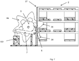
- Figures 1a and 1b show the device 1 suitable for containing therein the pallet stack 2 ( Figure 2 ); in detail, the device 1 has a central body consisting of a first side element 21, a second side element 22, parallel to each other, and a rear element 23 for connecting the side elements 21, 22 so as to delimit an empty area 24 in between them suitable to contain a plurality of pallets 2 stacked one on top of the other.
- the central body of the device 1 is also provided with an opening 25 between the side elements 21, 22 on the opposite side of the rear element 23 so as to substantially assume the shape of a U, wherein the opening 25 allows the passage of at least one pallet 2 for its/their insertion/removal in/from the empty area 24.
- Figures 1-3 show a first shaft 3a arranged in the lower part of the device 1, along the first side element 21 towards the outside with respect to the area 24 suitable for containing the pallets 2; similarly, a second shaft 3b visible in Figure 1b is positioned along the second side element 22, towards the outside.
- the two shafts 3a and 3b are connected to each other by means of the connector 29 at the rear element 23, so that the shaft 3a rotates in the opposite direction with respect to the other shaft 3b.
- a wheel assembly is mounted on each of the shafts 3a and 3b (shown in detail in Figures 3-5 ) with different functions.
- Figures 1a and 1b show the presence of a) a first petal wheel 4a and a ratchet wheel 5, integral with each other, arranged at a first end of the first shaft 3a, on the side of the opening 25, and of b) a second petal wheel 4b, arranged on the same first shaft 3a, at its opposite end.
- Both the petal wheels 4a and 4b are integral with the rotation of the first shaft 3a; therefore, the rotation of the shaft 3a simultaneously determines the rotation of the two petal wheels 4a, 4b and of the ratchet wheel 5.
- Figures 1a and 1b show the petal wheel 4c and a ratchet wheel 5, integral with each other, arranged at a first end of the second shaft 3b, on the side of the opening 25, and a second petal wheel 4d, arranged on the same second shaft 3b, at its opposite end.
- the petal wheel 4 in the specific case shown in Figures 4-12 has six petals 26, although, in other embodiments, the number of petals may be different, without changing the functional aspect.
- a petal 26 of each of the petal wheels 4a, 4b is able to fit into the corresponding slots 27, 27b formed along the height of the first side element 21; similarly, a petal 26 of each of the petal wheels 4c, 4d is able to fit into the corresponding slots 27c, 27d formed along the height of the second side element 22.
- the ratchet wheel 5 (shown in detail in Figures 3-5 ) engages with the ratchet tooth 6 to support the pallet stack 2 or is released from it to allow the descent of one or more pallets 2.
- the ratchet tooth 6 operates the pin 8 by means of the lever 7 along the cam path 9.
- the device 1 of the first embodiment of the present invention acts in the manner described below where, with reference to Figures 6-9 , the Steps 1.1-1.4 refer to the loading operation of a pallet 2 in a stack.
- Figure 6 shows a side view wherein both the wheel assembly on the left of the pallet stack 2, which includes the petal wheel 4a and the corresponding ratchet wheel 5, and the wheel assembly on the right of the pallet stack 2, which comprises the petal wheel 4c and the corresponding ratchet wheel 5, are visible, the two wheel assemblies being substantially identical.
- Figures 7-12 show only the wheel assembly comprising the petal wheel 4a.
- Phases 1.5-1.7 refer to the unloading operation of one or more pallets 2 from the stack itself.
- Figure 6 shows the pallet stack 2 raised, the ratchet tooth 6 engaged, the pin 8 in the lower position, and an entrance opening of about 170mm such as to allow a new pallet to be inserted and raised.
- the new inserted pallet is raised; in a first phase, going up, it pushes any pallet already present upwards; the upper axis of the pallet (or the lower axis of the pallet already present) comes up against the lower side of the petal 26 by rotating the petal wheel 4 which drags the shaft 3 and the ratchet wheel 5.
- the ratchet wheel 5 rotates the lever 7 which raises the pin 8 along the forward path of the cam 9 to the intermediate position. Meanwhile, a new petal 26' of the petal wheel 4, adjacent to the petal 26 above, is being inserted inside the pallet 2 just inserted therein.
- the lifting of the new inserted pallet 2 proceeds; the rotation of the petal wheel 4, and therefore the rotation of the ratchet wheel 5, again move the lever 7 which firstly lifts the pin 8 further along the cam path 9 up to the high position passing the end, then lowers it along the return of the same cam path 9.
- the ratchet wheel 5 presents a new coupling point inside which the ratchet tooth 6 "falls".
- the weight of the pallet stack 2 which then integrates the new pallet, causes the petal wheel 4 and the ratchet wheel 5 to rotate in the opposite direction, the latter becoming locked as it hooks to the ratchet tooth 6.
- the pallet truck is thus made weight free and can be extracted, the entire pallet stack 2 being supported by the system now; a new pallet may be inserted therein or the one just inserted may be withdrawn.
- the pallet truck can be inserted to pick up a pallet.
- the pallet truck goes up, it comes up against the lower pallet 2 and lifts the whole stack.
- the lower axis of the pallet 2 at the base of the stack come up against the petal 26 of the petal wheel 4, causing its rotation.
- the petal wheel 4 drags the shaft 3 and the ratchet wheel 5.
- the ratchet wheel 5 rotates the lever 7 which lifts the pin 8 along the forward path of the cam 9 to the intermediate position.
- the entire pallet stack 2 goes down and the petal wheels 4 and ratchet 5 rotate in the opposite direction.
- the ratchet wheel 5 shows the coupling point in correspondence with the ratchet tooth 6, which however does not engage because it is kept raised by the pin 8 and by the lever 7, thus allowing the ratchet wheel 5 to continue its rotation and therefore the descent of the pallet stack 2.
- the ratchet wheel 5 again moves the lever 7 which firstly raises the pin 8 further along the cam path 9 up to the high position to pass the end, then lowers it along the return of the same cam path 9.
- the ratchet wheel 5 presents a new coupling point inside which the ratchet tooth 6 "falls".
- the petal 26 of the petal wheel 4 which was inserted in the lower pallet 2 is removed from the pallet itself.
- the ratchet wheel 5 and the petal wheel 4 lock, preventing the stack from descending, which then releases the lower pallet 2 which is supported by the pallet truck.
- the lower pallet is sufficiently detached from the upper pallet but not yet resting on the ground, it can be extracted by removing the pallet truck.
- the device of the first embodiment of the present invention shown in detail with reference to Figures 1-12 uses only mechanical elements and means (shafts, petal wheels, ratchet wheels, pins, engagement elements), without the use of any electrical, pneumatic or hydraulic component.
- the movements necessary to stack and unstack the pallets are directly derived from the movement of the pallet truck, by which the pallet itself is inserted therein or removed therefrom.
- the pallet truck, coming into contact with the device of the present invention causes a movement of the shafts and of the wheels constrained to the shafts. No external power supply is therefore required, such as electric, pneumatic or hydraulic.
- the device of the present invention it is not necessary to select the stacking or unstacking function, because the movements necessary for one or the other action are automatically activated without any selection by the operator: if a pallet is inserted, then it is automatically stacked, otherwise, if only the pallet truck is inserted, then a pallet is picked up from the stack.
- the device of the present invention allows the withdrawal of the entire pallet stack or only a part of it, as well as the storage of one or more pallets stacked one on top of the other.
- the lifting bar 10 is arranged substantially horizontal, transversely with respect to the first and second side elements 21,22, in correspondence with the opening 25, at a height from the support surface of the device 1 sufficient to allow the passage of a pallet 2 below it (see in particular Figures 13-15 ).
- the multiplier system consists of a rack 11, a toothed wheel 12 equipped with a non-return lever 13 and a free wheel 14 equipped with a teeth system 15 and connected to the shaft 3 (see in particular Figure 16 ).
- the lifting bar 10 engages with the shaft 3 so as to determine its rotation and, consequently, the rotation of the petal wheel 4, when the bar 10 is lifted by a pallet truck or by other similar mechanical device (not shown in the figures).
- the petal wheel 4 in this way raises the pallets 2 beyond the maximum height normally reachable by the pallet truck.
- the anti-return lever 13 freely rotates the toothed wheel 12 clockwise with respect to the free wheel 14 (see Figure 16 in detail), on the contrary it drags it if it rotates in the opposite direction by gripping the teeth system 15.
- an abutment 16 integral with it comes up against the anti-return lever 13 making it rotate and freeing the teeth system 15, thus allowing clockwise rotation of the free wheel 14 with respect to the toothed wheel 12 for the complete descent of the pallet stack 2.
- the device 1 of the second embodiment of the present invention acts in the manner described below where, with reference to Figures 18-21 , Phases 2.1-2.4 refer to the loading operation of a pallet 2 in a stack, while, with reference to Figures 22-29 , Phases 2.5-2.12 refer to the unloading operation of one or more pallets 2 from the stack itself.
- Figure 18 shows a side view wherein both the wheel assembly on the left of the pallet stack 2, which includes the petal wheel 4a and the corresponding ratchet wheel 5, and the wheel assembly on the right of the pallet stack 2, which comprises the petal wheel 4c and the corresponding ratchet wheel 5, are visible, the two wheel assemblies being substantially identical.
- Figures 19-29 only show the wheel assembly comprising the petal wheel 4a.
- Figure 18 shows the pallet stack 2 raised, the ratchet tooth 6 engaged, the pin 8 in the lower position, the lifting bar 10 in the lower position, an entrance opening of about 170 mm such as to allow a new pallet to be inserted therein and raised.
- the new pallet 2 is inserted and raised until the forks of the pallet truck come up against the lifting bar 10 which lifts the entire pallet stack 2; in this phase the lower axis of the upper pallet, coming up against the petal 26, rotates the petal wheel 4a which drags the shaft 3, the ratchet wheel 5 and the free wheel 14.
- the ratchet wheel 5 rotates the lever 7 which raises the pin 8 along the forward path of the cam 9 up to the intermediate position; the freewheel 14 rotates until the teeth system 15 passes the anti-return lever 13 which rotates and returns to its position. From this moment on, the thrust of the pallet truck directly acts on the lifting bar 10.
- the pallet truck pushes the lifting bar 10 upwards which by the rack 11 rotates the toothed wheel 12 which, by means of the anti-return lever 13, grips the teeth system 15 of the free wheel 14, allowing the last one and, consequently, the shaft 3 and the petal wheel 4a, to counterclockwise rotate thus causing the further lifting of the whole pallet stack 2.
- the ratchet wheel 5 moves the lever 7 which firstly raises the pin 8 further along the path cam 9 up to the high position to pass the tip and then lowers it along the return of the same cam path 9.
- the rotation generated by the thrust on the bar 10 is such that the ratchet wheel 5 presents a new coupling point where the tooth ratchet 6 engages with to support the whole pallet stack 2 which then integrates the new pallet 2.
- the whole system starts moving: the weight of the pallet stack 2 pushes the petal wheel 4a downwards causing therefore its clockwise rotation which, by the shaft 3, drives the free wheel 14 which, in turn, by the anti-return lever 13 hooked to the teeth system 15, causes the rotation in the same direction of the toothed wheel 12 which pushes the lifting bar 10 downwards.
- the ratchet tooth 6 is detached from the ratchet wheel 5 and then passes the coupling point.
- the pin 8 maintains the tooth in a detached position, locked in the intermediate position of the cam 9.
- the ratchet tooth 6 encounters a protrusion in the ratchet wheel 5 which further rotates the lever 7 and further raises the pin 8 along the forward path in the cam 9 allowing it to reach the high and inversion position.
- the ratchet lever 7 leaves the projection and pushes the pin 8 along the return path of the cam 9.
- the lower part of the pallet 2 reaches the forks of the pallet truck; from this moment on the weight of the pallet stack 2 rests directly on the pallet truck thus weight relieving the lifting bar 10, the rack 11 and the anti-return lever 13 in the following millimeters of downward stroke.
- the lever 13, moving upwards comes up against the abutment 16 integral with the lifting bar 10 moving downwards.
- the abutment 16 rotates the lever 13 in an anticlockwise direction thus going out of the engagement range of the teeth system 15, the lifting bar 10 comes to rest on the bottom at the stroke end.
- the last descent phase of the pallet truck accompanies the pallet 2 detachment which, when it is lower than the lifting bar 10 but not yet resting on the ground, can be extracted.
- the device of the second embodiment of the present invention described above thanks to the use of a system that multiplies its lifting stroke, allows to use a normal manual pallet truck, whose stroke would otherwise be limited in the use of the system described above with reference to the first embodiment.
Landscapes
- Engineering & Computer Science (AREA)
- Mechanical Engineering (AREA)
- Handcart (AREA)
- De-Stacking Of Articles (AREA)
Abstract
Description
- The present invention refers to a device for moving pallets. In particular, the present invention refers to a device for moving pallets which does not require any kind of feeding.
- Devices such as platforms or pallets are known on the market, typically referred to by the term "pallets", which are used to support various types of material placed onto them to facilitate their transport and storage.
- These pallets are handled by specific equipment, such as forklifts or pallet trucks.
- On the market there are different types of stackers/destackers for moving pallets; these devices are used to stack empty pallets one on top of the other after they have been freed from their load, or when they must be stored in an orderly manner until their next use. When needed, the destacker will take from the stack the number of pallets necessary for a new operation of loading objects onto the pallets for a new transport.
- The known in the art stackers/destackers need at least a sort of power supply, some even pneumatic supply because the movements necessary to stack and unstack the pallets are generally driven by electric motors or by pneumatic or hydraulic pistons.
- This makes them expensive and requiring a connecting point to supply power; the latter can be a problem when the space where the pallets must be stacked or unstacked is very large, for example in a courtyard or in a shed far from socket points for electricity connection.
- Furthermore, the known in the art stackers/destackers require to select the stacking or unstacking function, depending on the request, before proceeding with one or the other action.
- The Chinese utility model published with no.
CN206692003U discloses a forkshaped machine for moving pallets comprising a piece of wheel which is provided with a plurality of trays which are in contact with each other. A spindle mechanism is equipped with a ratchet capable of synchronous rotation with the piece of wheel and a pawl for forward limitation and a pawl for backward limitation. A limiting mechanism used to limit the reversing assembly rotating towards the direction of application of the tray, and a driving device used to control the limiting direction of the reversing assembly. - The Applicant of the present patent application has underlined the need to achieve a stacker/unstacker for pallets solving the above highlighted technical problems, and in particular not requiring any type of power supply (electric, pneumatic, hydraulic, etc.).
- According to a first aspect, the present invention relates to a pallet stacker/destacker such as the one indicated in
claim 1. - The present invention derives in fact from the general consideration according to which the above highlighted technical problem can be solved in an effective and reliable way by means of a device for moving pallets comprising a central body consisting of a first side element and a second side element, parallel one each other, and a rear element for connecting the side elements one each other so as to delimit in between them an empty area adapted to contain a plurality of pallets stacked one above the other, wherein said central body is further provided with an opening between said side elements disposed on the opposite side of said rear element so as to substantially assume a U-shape, wherein said opening is able to allow the passage of at least one pallet for its/their insertion/removal into/from said empty area.
- The pallet handling device of the present invention is characterized in that it is also provided with:
- at least one first shaft arranged along said first side element and at least one second shaft arranged along said second side element, said shafts being both arranged towards the outside of the device with respect to said empty area;
- at least one first ratchet wheel able to integrally rotate with said first shaft and a second ratchet wheel able to integrally rotate with said second shaft, wherein each of said ratchet wheels is adapted to engage/disengage with a corresponding stop tooth to support said pallet stack or to release it to allow it to descend.
- In this way, the device of the present invention uses only mechanical elements and means (such as, for example, shafts and wheels with engagement elements), without the aid of any electrical, pneumatic or hydraulic component, solving the highlighted above technical problem.
- Furthermore, the movements required to stack and unstack the pallets are directly derived from the movement of the pallet truck (or from another handling and lifting system) by which the pallet is inserted therein or removed therefrom. In fact, the pallet truck, coming into contact with the device of the present invention, causes a movement of the shafts and of the wheels constrained to the shafts.
- No external power supply such as electric or pneumatic or hydraulic supply is therefore required.
- In addition, by means of the device of the present invention, it is not necessary to select the stacking or unstacking function, because the movements necessary for one or the other action are automatically activated without any selection by the operator: if a pallet is inserted, then it is automatically stacked, otherwise, if only the pallet truck is inserted, then a pallet is picked up from the stack.
- Furthermore, the device of the present invention allows the withdrawal of the entire pallet stack or only a part of it, as well as the storage of one or more pallets stacked one on top of the other.
- The device for moving pallets of the present invention can be used in particular with pallet trucks (usually less common on the market) capable of lifting a pallet or a pallet stack even beyond a standard height, for example up to about 250 mm.
- According to a preferred embodiment, said first and second shaft are connected one each other by a fitting device at the rear element.
- In this way, the first shaft rotates in the opposite direction with respect to the second shaft, and vice versa.
- According to a preferred embodiment, each of said ratchet wheels is able to rotate integrally with a corresponding first and second petal wheel, each provided with petal engagement elements, such as protuberances radially arranged towards the outside of the wheel itself, and wherein the pitch between one petal and the other one is such as to allow one petal at a time to be inserted into a cavity laterally formed in a reference pallet.
- In this way, said ratchet wheel is adapted to engage/disengage with a stop tooth in order to support said pallet stack or to release it to allow its descent.
- According to a preferred embodiment, the device of the present invention further comprises one lever for each of said stop tooth with which the lever engages to allow the rotation of said ratchet wheel.
- According to a preferred embodiment, the device of the present invention further comprises a pin operable by said lever and arranged along a cam path.
- In this way, the pin allows the ratchet tooth to be disengaged from the ratchet wheel to allow it to rotate clockwise and therefore the pallet stack to descend.
- According to a preferred embodiment, the device of the present invention also comprises at least one substantially horizontal arranged lifting bar, transversely disposed with respect to said first and second side element, at said opening, and such as to be constrained at one of its first ends with said at least one first shaft and at a second end thereof, opposite said first end, with said at least one second shaft, wherein said lifting bar is able to be vertically moved downwards or upwards in such a way to cause the consequent rotation of each of said first and second shaft and of the corresponding ratchet wheel integral with it so that the consequent displacement of said engagement elements of said first and second petal wheel allows, respectively, the mechanical lifting or lowering of said reference pallet.
- In this way, the rotation of each shaft, once activated by the lifting/lowering of the lifting bar, causes the corresponding upward/downward displacement of the petal of the petal wheel which disengages from the pallet to which it was attached.
- According to a preferred embodiment, the device of the present invention further comprises, for each of said first and second shaft, a multiplier system associated therewith, able to rotate said petal wheel according to said displacement of said lifting bar, wherein said multiplier system consists at least of a rack, a toothed wheel and a free wheel provided with teeth system, wherein said free wheel is connected to the corresponding shaft with which said multiplier system is associated.
- In this way, said multiplier system allows the rotation of the petal wheel which in about 20 mm of stroke allows a pallet to be lifted to a height equal to its height.
- Thanks to the presence of the lifting bar and of the multiplier system connected to it, the device of this preferred embodiment of the present invention can also be used by pallet trucks, typically available on the market, capable of lifting the pallet stack up to a pre-established maximum height, typically up to 190/200 mm.
- According to a preferred embodiment, said toothed wheel is provided with an anti-return lever.
- In this way, the anti-return lever is able to clockwise freely rotate said toothed wheel with respect to said free wheel, or to drag it by gripping said teeth system if it rotates in the opposite direction.
- According to a preferred embodiment, said multiplier system further comprises an abutment integral with said lifting bar.
- In this way, said abutment allows the rotation of the anti-return lever so as to free up said teeth system from engagement and consequently allowing the clockwise rotation of said free wheel with respect to the toothed wheel to allow complete descent of the pallet stack.
- According to a preferred embodiment, said lifting bar is placed at a height with respect to the support surface of the device which is greater than the height of said reference pallet.
- In this way, when the lifting bar is in the lower position, its height from the ground of about 170 mm allows the insertion of a new pallet and, subsequently, its lifting together with the entire pallet stack above it.
- Additional features and advantages of the present invention will be better highlighted by examining the following detailed description of a preferred but not exclusive embodiment, illustrated by way of non-limiting example, with the support of the attached drawings, wherein:
-
Figure 1a is an axonometric view of a first embodiment of a device according to the present invention; -
Figure 1b shows the same view ofFigure 1a wherein the parts not visible inFigure 1a are hatching highlighted; -
Figure 2 is an axonometric view of the device ofFig. 1 inside which a pallet stack is arranged; -
Figure 3 is an axonometric detail of the device ofFig. 1a , wherein the wheel assembly formed by petal wheel, ratchet wheel and free wheel is shown; -
Figure 4 is a side view showing the pallet stack ofFig. 2 and the petal wheels ofFig. 1-3 ; -
Figure 5 is a front view showing in details the ratchet wheel and the petal wheel ofFig. 3 ; -
Figures 6-9 show the front views of various sequential phases for loading pallets; -
Figures 10-12 show the front views of various sequential phases for unloading pallets; -
Figure 13 is an axonometric view of a second embodiment of a device according to the present invention, wherein a lifting bar is visible; -
Figure 14 is a detail ofFigure 13 wherein the multiplier system is shown; -
Figure 15 is an axonometric view of the device ofFig. 13 inside which a pallet stack is arranged; -
Figure 16 is a front view of the wheel assembly ofFig. 14 ; -
Figure 17 is a detail of the anti-return lever shown inFig. 16 ; -
Figures 18-21 show the front views of various sequential phases for loading pallets using the device ofFig. 13 ; -
Figures 22-29 show the front views of various sequential phases for unloading pallets using the device ofFig. 13 . - The following detailed description refers to a first embodiment of the present invention shown with reference to
Figures 1-12 and to a second embodiment of the present invention shown with reference toFigures 13-29 . - In particular, in the first embodiment,
Figures 1a and 1b show thedevice 1 suitable for containing therein the pallet stack 2 (Figure 2 ); in detail, thedevice 1 has a central body consisting of afirst side element 21, asecond side element 22, parallel to each other, and arear element 23 for connecting theside elements empty area 24 in between them suitable to contain a plurality ofpallets 2 stacked one on top of the other. The central body of thedevice 1 is also provided with anopening 25 between theside elements rear element 23 so as to substantially assume the shape of a U, wherein theopening 25 allows the passage of at least onepallet 2 for its/their insertion/removal in/from theempty area 24. -
Figures 1-3 show afirst shaft 3a arranged in the lower part of thedevice 1, along thefirst side element 21 towards the outside with respect to thearea 24 suitable for containing thepallets 2; similarly, asecond shaft 3b visible inFigure 1b is positioned along thesecond side element 22, towards the outside. In the embodiment shown inFigure 1b , the twoshafts connector 29 at therear element 23, so that theshaft 3a rotates in the opposite direction with respect to theother shaft 3b. - A wheel assembly is mounted on each of the
shafts Figures 3-5 ) with different functions. In particular,Figures 1a and 1b show the presence of a) afirst petal wheel 4a and aratchet wheel 5, integral with each other, arranged at a first end of thefirst shaft 3a, on the side of theopening 25, and of b) asecond petal wheel 4b, arranged on the samefirst shaft 3a, at its opposite end. Both thepetal wheels first shaft 3a; therefore, the rotation of theshaft 3a simultaneously determines the rotation of the twopetal wheels ratchet wheel 5. - Similarly, the same wheel assembly is also mounted on the
second shaft 3b. In particular,Figures 1a and 1b show thepetal wheel 4c and aratchet wheel 5, integral with each other, arranged at a first end of thesecond shaft 3b, on the side of theopening 25, and asecond petal wheel 4d, arranged on the samesecond shaft 3b, at its opposite end. - The petal wheel 4 in the specific case shown in
Figures 4-12 has sixpetals 26, although, in other embodiments, the number of petals may be different, without changing the functional aspect. Apetal 26 of each of thepetal wheels slots first side element 21; similarly, apetal 26 of each of thepetal wheels slots second side element 22. - The ratchet wheel 5 (shown in detail in
Figures 3-5 ) engages with theratchet tooth 6 to support thepallet stack 2 or is released from it to allow the descent of one ormore pallets 2. Theratchet tooth 6 operates thepin 8 by means of thelever 7 along thecam path 9. - Operatively, the
device 1 of the first embodiment of the present invention acts in the manner described below where, with reference toFigures 6-9 , the Steps 1.1-1.4 refer to the loading operation of apallet 2 in a stack.Figure 6 shows a side view wherein both the wheel assembly on the left of thepallet stack 2, which includes thepetal wheel 4a and thecorresponding ratchet wheel 5, and the wheel assembly on the right of thepallet stack 2, which comprises thepetal wheel 4c and thecorresponding ratchet wheel 5, are visible, the two wheel assemblies being substantially identical. Vice versa, for the sake of simplicity,Figures 7-12 show only the wheel assembly comprising thepetal wheel 4a. With reference toFigures 10-12 , Phases 1.5-1.7 refer to the unloading operation of one ormore pallets 2 from the stack itself. -
Figure 6 shows thepallet stack 2 raised, theratchet tooth 6 engaged, thepin 8 in the lower position, and an entrance opening of about 170mm such as to allow a new pallet to be inserted and raised. - The new inserted pallet is raised; in a first phase, going up, it pushes any pallet already present upwards; the upper axis of the pallet (or the lower axis of the pallet already present) comes up against the lower side of the
petal 26 by rotating the petal wheel 4 which drags the shaft 3 and theratchet wheel 5. Theratchet wheel 5 rotates thelever 7 which raises thepin 8 along the forward path of thecam 9 to the intermediate position. Meanwhile, a new petal 26' of the petal wheel 4, adjacent to thepetal 26 above, is being inserted inside thepallet 2 just inserted therein. - In a second phase, the lifting of the new inserted
pallet 2 proceeds; the rotation of the petal wheel 4, and therefore the rotation of theratchet wheel 5, again move thelever 7 which firstly lifts thepin 8 further along thecam path 9 up to the high position passing the end, then lowers it along the return of thesame cam path 9. As the rotation proceeds, theratchet wheel 5 presents a new coupling point inside which theratchet tooth 6 "falls". - At this point, letting the pallet truck go down, the weight of the
pallet stack 2, which then integrates the new pallet, causes the petal wheel 4 and theratchet wheel 5 to rotate in the opposite direction, the latter becoming locked as it hooks to theratchet tooth 6. The pallet truck is thus made weight free and can be extracted, theentire pallet stack 2 being supported by the system now; a new pallet may be inserted therein or the one just inserted may be withdrawn. - Starting from the position in PHASE 1.4 (
pallet stack 2 raised, ratchettooth 6 hooked,pin 8 in the lower position, entry opening of about 170 mm) the pallet truck can be inserted to pick up a pallet. As the pallet truck goes up, it comes up against thelower pallet 2 and lifts the whole stack. The lower axis of thepallet 2 at the base of the stack come up against thepetal 26 of the petal wheel 4, causing its rotation. As in the pallet insertion phase, the petal wheel 4 drags the shaft 3 and theratchet wheel 5. Theratchet wheel 5 rotates thelever 7 which lifts thepin 8 along the forward path of thecam 9 to the intermediate position. - At this point, by letting the pallet truck go down, the
entire pallet stack 2 goes down and the petal wheels 4 and ratchet 5 rotate in the opposite direction. Theratchet wheel 5 shows the coupling point in correspondence with theratchet tooth 6, which however does not engage because it is kept raised by thepin 8 and by thelever 7, thus allowing theratchet wheel 5 to continue its rotation and therefore the descent of thepallet stack 2. Continuing in the rotation that accompanies the descent ofpallet stack 2, theratchet wheel 5 again moves thelever 7 which firstly raises thepin 8 further along thecam path 9 up to the high position to pass the end, then lowers it along the return of thesame cam path 9. - Continuing the descent and rotation, the
ratchet wheel 5 presents a new coupling point inside which theratchet tooth 6 "falls". In the meantime, thepetal 26 of the petal wheel 4 which was inserted in thelower pallet 2 is removed from the pallet itself. At this point, theratchet wheel 5 and the petal wheel 4 lock, preventing the stack from descending, which then releases thelower pallet 2 which is supported by the pallet truck. When the lower pallet is sufficiently detached from the upper pallet but not yet resting on the ground, it can be extracted by removing the pallet truck. - In this way, the device of the first embodiment of the present invention shown in detail with reference to
Figures 1-12 uses only mechanical elements and means (shafts, petal wheels, ratchet wheels, pins, engagement elements), without the use of any electrical, pneumatic or hydraulic component. Furthermore, the movements necessary to stack and unstack the pallets are directly derived from the movement of the pallet truck, by which the pallet itself is inserted therein or removed therefrom. In fact, the pallet truck, coming into contact with the device of the present invention, causes a movement of the shafts and of the wheels constrained to the shafts. No external power supply is therefore required, such as electric, pneumatic or hydraulic. - In addition, by means of the device of the present invention, it is not necessary to select the stacking or unstacking function, because the movements necessary for one or the other action are automatically activated without any selection by the operator: if a pallet is inserted, then it is automatically stacked, otherwise, if only the pallet truck is inserted, then a pallet is picked up from the stack.
- Furthermore, the device of the present invention allows the withdrawal of the entire pallet stack or only a part of it, as well as the storage of one or more pallets stacked one on top of the other.
- With reference to
Figures 13-29 , a second embodiment of the present invention is shown. - To the device of the first embodiment of the present invention, described above with reference to
Figures 1-12 , a liftingbar 10 and a multiplier system are added here in this second embodiment of the present invention, as shown in detail inFigures 13 -17 . - The lifting
bar 10 is arranged substantially horizontal, transversely with respect to the first andsecond side elements opening 25, at a height from the support surface of thedevice 1 sufficient to allow the passage of apallet 2 below it (see in particularFigures 13-15 ). - The multiplier system consists of a
rack 11, atoothed wheel 12 equipped with anon-return lever 13 and afree wheel 14 equipped with ateeth system 15 and connected to the shaft 3 (see in particularFigure 16 ). - The lifting
bar 10 engages with the shaft 3 so as to determine its rotation and, consequently, the rotation of the petal wheel 4, when thebar 10 is lifted by a pallet truck or by other similar mechanical device (not shown in the figures). The petal wheel 4 in this way raises thepallets 2 beyond the maximum height normally reachable by the pallet truck. - The
anti-return lever 13 freely rotates thetoothed wheel 12 clockwise with respect to the free wheel 14 (seeFigure 16 in detail), on the contrary it drags it if it rotates in the opposite direction by gripping theteeth system 15. Near the lower position of the liftingbar 10, anabutment 16 integral with it (seeFigure 17 in detail) comes up against theanti-return lever 13 making it rotate and freeing theteeth system 15, thus allowing clockwise rotation of thefree wheel 14 with respect to thetoothed wheel 12 for the complete descent of thepallet stack 2. - Operatively, the
device 1 of the second embodiment of the present invention acts in the manner described below where, with reference toFigures 18-21 , Phases 2.1-2.4 refer to the loading operation of apallet 2 in a stack, while, with reference toFigures 22-29 , Phases 2.5-2.12 refer to the unloading operation of one ormore pallets 2 from the stack itself. -
Figure 18 shows a side view wherein both the wheel assembly on the left of thepallet stack 2, which includes thepetal wheel 4a and thecorresponding ratchet wheel 5, and the wheel assembly on the right of thepallet stack 2, which comprises thepetal wheel 4c and thecorresponding ratchet wheel 5, are visible, the two wheel assemblies being substantially identical. Vice versa, for the sake of simplicity,Figures 19-29 only show the wheel assembly comprising thepetal wheel 4a. -
Figure 18 shows thepallet stack 2 raised, theratchet tooth 6 engaged, thepin 8 in the lower position, the liftingbar 10 in the lower position, an entrance opening of about 170 mm such as to allow a new pallet to be inserted therein and raised. - The
new pallet 2 is inserted and raised until the forks of the pallet truck come up against the liftingbar 10 which lifts theentire pallet stack 2; in this phase the lower axis of the upper pallet, coming up against thepetal 26, rotates thepetal wheel 4a which drags the shaft 3, theratchet wheel 5 and thefree wheel 14. Theratchet wheel 5 rotates thelever 7 which raises thepin 8 along the forward path of thecam 9 up to the intermediate position; thefreewheel 14 rotates until theteeth system 15 passes theanti-return lever 13 which rotates and returns to its position. From this moment on, the thrust of the pallet truck directly acts on the liftingbar 10. - The pallet truck pushes the lifting
bar 10 upwards which by therack 11 rotates thetoothed wheel 12 which, by means of theanti-return lever 13, grips theteeth system 15 of thefree wheel 14, allowing the last one and, consequently, the shaft 3 and thepetal wheel 4a, to counterclockwise rotate thus causing the further lifting of thewhole pallet stack 2. During rotation, theratchet wheel 5 moves thelever 7 which firstly raises thepin 8 further along thepath cam 9 up to the high position to pass the tip and then lowers it along the return of thesame cam path 9. The rotation generated by the thrust on thebar 10 is such that theratchet wheel 5 presents a new coupling point where thetooth ratchet 6 engages with to support thewhole pallet stack 2 which then integrates thenew pallet 2. - Letting the pallet truck go down, it accompanies the descent of the lifting
bar 10 only to its lowest position; during this descent therack 11 rotates thetoothed wheel 12 in a clockwise direction, therefore without dragging thefree wheel 14. At this point, anew pallet 2 can be inserted therein or removed therefrom. - Starting from the position in PHASE 2.4 (
pallet stack 2 raised, ratchettooth 6 hooked,pin 8 and liftingbar 10 in the lower positions, entrance opening such as to allow the insertion of the pallet truck to pick up a pallet 2), the pallet truck is raised; the latter comes up against the liftingbar 10 which rotates thetoothed wheel 12 by means of therack 11. Theanti-return lever 13 does not engage theteeth system 15 because this is located before the lever itself along the rotation path. This part of the climb is therefore in neutral gear. - While the pallet truck goes on to raise, the
toothed wheel 12 continues to rotate, theanti-return lever 13 comes up against theteeth system 15 of thefree wheel 14, allowing all the elements on the axis,petal wheel 4a andwheel ratchet 5, to start rotating. Thepetal wheel 4a allows thepallets 2 to rise and theratchet wheel 5 pushes thelever 7 which raises thepin 8 along the forward path of thecam 9 up to the intermediate position, locking thelever 7 in this position. At this time all the load is supported by the liftingbar 10. - By lowering the pallet truck, the whole system starts moving: the weight of the
pallet stack 2 pushes thepetal wheel 4a downwards causing therefore its clockwise rotation which, by the shaft 3, drives thefree wheel 14 which, in turn, by theanti-return lever 13 hooked to theteeth system 15, causes the rotation in the same direction of thetoothed wheel 12 which pushes the liftingbar 10 downwards. In the first rotation phase theratchet tooth 6 is detached from theratchet wheel 5 and then passes the coupling point. Thepin 8 maintains the tooth in a detached position, locked in the intermediate position of thecam 9. - Continuing in the descent and consequently in the rotation phase, the
ratchet tooth 6 encounters a protrusion in theratchet wheel 5 which further rotates thelever 7 and further raises thepin 8 along the forward path in thecam 9 allowing it to reach the high and inversion position. - Continuing in the descent and consequently in the rotation phase, the
ratchet lever 7 leaves the projection and pushes thepin 8 along the return path of thecam 9. - Continuing in the descent and consequently in the rotation phase, the lower part of the
pallet 2 reaches the forks of the pallet truck; from this moment on the weight of thepallet stack 2 rests directly on the pallet truck thus weight relieving the liftingbar 10, therack 11 and theanti-return lever 13 in the following millimeters of downward stroke. Precisely in this phase, thelever 13, moving upwards, comes up against theabutment 16 integral with the liftingbar 10 moving downwards. In the following millimeters of stroke, theabutment 16 rotates thelever 13 in an anticlockwise direction thus going out of the engagement range of theteeth system 15, the liftingbar 10 comes to rest on the bottom at the stroke end. - At this point the descent of the
pallet stack 2, restrained by the pallet truck, causes thepetal wheel 4a, theratchet wheel 5 and thefree wheel 14 to rotate; during this rotation, theratchet tooth 6 approaches the coupling point, thus blocking the whole system; thepin 8 completes the return stroke in thecam 9 down to the bottom, resetting itself. - The last descent phase of the pallet truck accompanies the
pallet 2 detachment which, when it is lower than the liftingbar 10 but not yet resting on the ground, can be extracted. - The device of the second embodiment of the present invention described above, thanks to the use of a system that multiplies its lifting stroke, allows to use a normal manual pallet truck, whose stroke would otherwise be limited in the use of the system described above with reference to the first embodiment.
- Naturally, many modifications and variations of the preferred embodiment described above will be evident to those skilled in the art, still remaining within the scope of the invention.
- Therefore, the present invention is not limited to the preferred embodiment described, illustrated only by way of non-limiting example, but is defined by the following claims.
Claims (10)
- Device (1) for moving pallets (2) comprising a central body consisting of a first side element (21) and a second side element (22), parallel one each other, and a rear element (23) for connecting the side elements (21,22) one each other so as to delimit an empty area (24) in between them adapted to contain a plurality of pallets (2) stacked one above the other, wherein said central body is further provided with an opening (25) between said side elements (21,22) on the opposite side of said rear element (23) so as to substantially assume a U-shape, wherein said opening (25) is able to allow the passage of at least one pallet (2) for its/their insertion/removal into/from said empty area (24),
characterized in that said device (1) is further provided with:- at least one first shaft (3a) arranged along said first side element (21) and at least one second shaft (3b) arranged along said second side element (22), said shafts (3a,3b) being both arranged towards the outside of the device (1) with respect to said empty area (24);- at least one first ratchet wheel (5a) able to integrally rotate with said first shaft (3a) and a second ratchet wheel (5b) able to integrally rotate with said second shaft (3b), wherein each of said ratchet wheels (5a, 5b) is adapted to engage/disengage with a corresponding stop tooth (6) to support said stack of pallets (2) or to release it (2) to allow it to descend. - Device (1) according to claim 1, wherein said first (3a) and second shaft (3b) are connected one each other by a fitting device (29) at the rear element (23), so that the first shaft (3a) rotates in the opposite direction to the second shaft (3b).
- Device (1) according to claim 1 or 2, wherein each of said ratchet wheels (5a, 5b) is able to integrally rotate with a corresponding first (4a) and second petal wheel (4b), each provided with petal engagement elements (26) and wherein the pitch between two successive petals (26) is such as to allow one petal (26) at a time to be inserted into a cavity laterally formed into a reference pallet (2).
- Device (1) according to any one of the preceding claims which further comprises one lever (7) for each of said stop tooth (6), engaging with it (6) to allow the rotation of said ratchet wheels (5a, 5b).
- Device (1) according to claim 4 which further comprises a pin (8) operable by said lever (7) and arranged along a cam path (9).
- Device (1) according to any one of the preceding claims 3-5, which further comprises at least one substantially horizontally arranged lifting bar (10), transversely disposed with respect to said first (21) and second side elements (22) at said opening (25), and able to be constrained with said at least one first shaft (3a) at one of its first ends, and with said at least one second shaft (3b) at a second end thereof, opposite to said first end, wherein said lifting bar (10) is able to be vertically moved downwards or upwards so as to cause the consequent rotation of each of said first (3a) and second shaft (3b) and of the corresponding ratchet wheel (5a, 5b) integral with it so that the consequent displacement of said engagement elements (26) of said first (4a) and second petal wheels (4b) allows, respectively, the mechanical lifting or lowering of said reference pallet (2).
- Device (1) according to claim 6 which further comprises, for each of said first (3a) and second shaft (3b), a multiplier system associated therewith capable of rotating said petal wheels (4a, 4b) according to said displacement of said lifting bar (10), wherein said multiplier system consists at least of a rack (11), a toothed wheel (12) and a free wheel (14) provided with teeth system (15), wherein said free wheel (14) is connected to the corresponding shaft (3a, 3b) to which said multiplier system is associated.
- Device (1) according to claim 7, wherein said toothed wheel (12) is provided with an anti-return lever (13) able to rotate said toothed wheel (12) in a clockwise direction relative to said free wheel (14), or to drag it by gripping said teeth system (15) if it rotates in the opposite direction.
- Device (1) according to claim 8, wherein said multiplier system further comprises an abutment element (16) integral with said lifting bar (10) and adapted to rotate said anti-return lever (13) in a manner to free up said teeth system (15) and consequently allowing the clockwise rotation of said free wheel (14) with respect to said toothed wheel (12) to allow the complete descent of the pallet stack (2).
- Device (1) according to any of the preceding claims 6-9 wherein said lifting bar (10) is placed at a height with respect to the supporting surface of the device (1) which is greater than the height of the reference pallet (2).
Applications Claiming Priority (1)
| Application Number | Priority Date | Filing Date | Title |
|---|---|---|---|
| IT102019000020420A IT201900020420A1 (en) | 2019-11-05 | 2019-11-05 | Pallet handling device |
Publications (3)
| Publication Number | Publication Date |
|---|---|
| EP3819239A1 true EP3819239A1 (en) | 2021-05-12 |
| EP3819239C0 EP3819239C0 (en) | 2024-02-21 |
| EP3819239B1 EP3819239B1 (en) | 2024-02-21 |
Family
ID=70480324
Family Applications (1)
| Application Number | Title | Priority Date | Filing Date |
|---|---|---|---|
| EP20020505.2A Active EP3819239B1 (en) | 2019-11-05 | 2020-11-02 | Device for moving pallets |
Country Status (2)
| Country | Link |
|---|---|
| EP (1) | EP3819239B1 (en) |
| IT (1) | IT201900020420A1 (en) |
Cited By (3)
| Publication number | Priority date | Publication date | Assignee | Title |
|---|---|---|---|---|
| CN114438904A (en) * | 2021-12-22 | 2022-05-06 | 中铁二十五局集团第二工程有限公司 | Long-span through-type continuous steel truss pushing process |
| CN114671183A (en) * | 2022-05-26 | 2022-06-28 | 南通绿达通市政园林有限公司 | Horticulture flowerpot stacking and conveying device |
| KR102660405B1 (en) * | 2023-03-03 | 2024-04-24 | 구진섭 | Loading Apparatus for Seed Box |
Citations (5)
| Publication number | Priority date | Publication date | Assignee | Title |
|---|---|---|---|---|
| US2693898A (en) * | 1951-07-17 | 1954-11-09 | Robert T Epperson | Pallet feeder |
| JPS5548130A (en) * | 1978-10-03 | 1980-04-05 | Satake Eng Co Ltd | Automatic feeder for pallet |
| JPS5964422A (en) * | 1982-10-04 | 1984-04-12 | Iwaguro Seisakusho:Kk | Ptp sheet stacking apparatus |
| DE102015010072B3 (en) * | 2015-08-03 | 2016-12-01 | Wilhelm Kamm | Pallet stacker |
| CN206692003U (en) | 2017-03-30 | 2017-12-01 | 深圳市凯通物流有限公司 | Pallet code extension set and its fork disk device |
-
2019
- 2019-11-05 IT IT102019000020420A patent/IT201900020420A1/en unknown
-
2020
- 2020-11-02 EP EP20020505.2A patent/EP3819239B1/en active Active
Patent Citations (5)
| Publication number | Priority date | Publication date | Assignee | Title |
|---|---|---|---|---|
| US2693898A (en) * | 1951-07-17 | 1954-11-09 | Robert T Epperson | Pallet feeder |
| JPS5548130A (en) * | 1978-10-03 | 1980-04-05 | Satake Eng Co Ltd | Automatic feeder for pallet |
| JPS5964422A (en) * | 1982-10-04 | 1984-04-12 | Iwaguro Seisakusho:Kk | Ptp sheet stacking apparatus |
| DE102015010072B3 (en) * | 2015-08-03 | 2016-12-01 | Wilhelm Kamm | Pallet stacker |
| CN206692003U (en) | 2017-03-30 | 2017-12-01 | 深圳市凯通物流有限公司 | Pallet code extension set and its fork disk device |
Cited By (3)
| Publication number | Priority date | Publication date | Assignee | Title |
|---|---|---|---|---|
| CN114438904A (en) * | 2021-12-22 | 2022-05-06 | 中铁二十五局集团第二工程有限公司 | Long-span through-type continuous steel truss pushing process |
| CN114671183A (en) * | 2022-05-26 | 2022-06-28 | 南通绿达通市政园林有限公司 | Horticulture flowerpot stacking and conveying device |
| KR102660405B1 (en) * | 2023-03-03 | 2024-04-24 | 구진섭 | Loading Apparatus for Seed Box |
Also Published As
| Publication number | Publication date |
|---|---|
| EP3819239C0 (en) | 2024-02-21 |
| EP3819239B1 (en) | 2024-02-21 |
| IT201900020420A1 (en) | 2021-05-05 |
Similar Documents
| Publication | Publication Date | Title |
|---|---|---|
| EP3819239B1 (en) | Device for moving pallets | |
| US11208264B2 (en) | System for storing and transporting objects stored in racks of a warehouse | |
| CN112407712B (en) | Container stacking magazine and loading vehicle | |
| US4197046A (en) | Palletizer | |
| US20130340393A1 (en) | Apparatus and method to fully automatically open crates for agricultural products | |
| CN217437146U (en) | Be applied to automatic lifting device of feed packaging bag pile up neatly | |
| CN105480725B (en) | Wheel carloader | |
| CN113602722B (en) | Loading auxiliary device for storing goods and using method | |
| GB2063839A (en) | Apparatus for loading goods into storage racks and for unloading goods therefrom | |
| CN116605668A (en) | Unstacking method and automatic unstacking device | |
| WO2014207680A1 (en) | A system and method for handling live poultry | |
| CN209871759U (en) | Tray feeder | |
| US20230322489A1 (en) | System for storage of goods carriers | |
| SU600040A1 (en) | Store for storing and delivering cylindrical articles | |
| JP5635062B2 (en) | Pallet feeder | |
| KR20230074264A (en) | Container storage and retrieval system | |
| IT202100003755U1 (en) | Pallet handling device | |
| JPH072532B2 (en) | Picking method | |
| CN210285539U (en) | Material jar is received and is sent device, AGV carrier loader and canned material automatic discharging device | |
| CN221564914U (en) | Automatic unstacking machine | |
| CN216918460U (en) | Automatic lifting machine convenient to goods are piled up | |
| CN218619175U (en) | Tray buttress finishing device is flowed in storehouse material | |
| CN218087228U (en) | Balance stacker | |
| JP3449455B2 (en) | Wafer transfer device | |
| CN218579581U (en) | Lifting frame for forklift |
Legal Events
| Date | Code | Title | Description |
|---|---|---|---|
| PUAI | Public reference made under article 153(3) epc to a published international application that has entered the european phase |
Free format text: ORIGINAL CODE: 0009012 |
|
| STAA | Information on the status of an ep patent application or granted ep patent |
Free format text: STATUS: THE APPLICATION HAS BEEN PUBLISHED |
|
| AK | Designated contracting states |
Kind code of ref document: A1 Designated state(s): AL AT BE BG CH CY CZ DE DK EE ES FI FR GB GR HR HU IE IS IT LI LT LU LV MC MK MT NL NO PL PT RO RS SE SI SK SM TR |
|
| STAA | Information on the status of an ep patent application or granted ep patent |
Free format text: STATUS: REQUEST FOR EXAMINATION WAS MADE |
|
| 17P | Request for examination filed |
Effective date: 20220120 |
|
| RBV | Designated contracting states (corrected) |
Designated state(s): AL AT BE BG CH CY CZ DE DK EE ES FI FR GB GR HR HU IE IS IT LI LT LU LV MC MK MT NL NO PL PT RO RS SE SI SK SM TR |
|
| GRAP | Despatch of communication of intention to grant a patent |
Free format text: ORIGINAL CODE: EPIDOSNIGR1 |
|
| STAA | Information on the status of an ep patent application or granted ep patent |
Free format text: STATUS: GRANT OF PATENT IS INTENDED |
|
| INTG | Intention to grant announced |
Effective date: 20230904 |
|
| GRAS | Grant fee paid |
Free format text: ORIGINAL CODE: EPIDOSNIGR3 |
|
| GRAA | (expected) grant |
Free format text: ORIGINAL CODE: 0009210 |
|
| STAA | Information on the status of an ep patent application or granted ep patent |
Free format text: STATUS: THE PATENT HAS BEEN GRANTED |
|
| AK | Designated contracting states |
Kind code of ref document: B1 Designated state(s): AL AT BE BG CH CY CZ DE DK EE ES FI FR GB GR HR HU IE IS IT LI LT LU LV MC MK MT NL NO PL PT RO RS SE SI SK SM TR |
|
| REG | Reference to a national code |
Ref country code: GB Ref legal event code: FG4D |
|
| REG | Reference to a national code |
Ref country code: CH Ref legal event code: EP |
|
| REG | Reference to a national code |
Ref country code: IE Ref legal event code: FG4D |
|
| REG | Reference to a national code |
Ref country code: DE Ref legal event code: R096 Ref document number: 602020025888 Country of ref document: DE |
|
| U01 | Request for unitary effect filed |
Effective date: 20240320 |
|
| U07 | Unitary effect registered |
Designated state(s): AT BE BG DE DK EE FI FR IT LT LU LV MT NL PT SE SI Effective date: 20240327 |
|
| PG25 | Lapsed in a contracting state [announced via postgrant information from national office to epo] |
Ref country code: IS Free format text: LAPSE BECAUSE OF FAILURE TO SUBMIT A TRANSLATION OF THE DESCRIPTION OR TO PAY THE FEE WITHIN THE PRESCRIBED TIME-LIMIT Effective date: 20240621 |
|
| PG25 | Lapsed in a contracting state [announced via postgrant information from national office to epo] |
Ref country code: GR Free format text: LAPSE BECAUSE OF FAILURE TO SUBMIT A TRANSLATION OF THE DESCRIPTION OR TO PAY THE FEE WITHIN THE PRESCRIBED TIME-LIMIT Effective date: 20240522 |
|
| PG25 | Lapsed in a contracting state [announced via postgrant information from national office to epo] |
Ref country code: RS Free format text: LAPSE BECAUSE OF FAILURE TO SUBMIT A TRANSLATION OF THE DESCRIPTION OR TO PAY THE FEE WITHIN THE PRESCRIBED TIME-LIMIT Effective date: 20240521 Ref country code: HR Free format text: LAPSE BECAUSE OF FAILURE TO SUBMIT A TRANSLATION OF THE DESCRIPTION OR TO PAY THE FEE WITHIN THE PRESCRIBED TIME-LIMIT Effective date: 20240221 |
|
| PG25 | Lapsed in a contracting state [announced via postgrant information from national office to epo] |
Ref country code: ES Free format text: LAPSE BECAUSE OF FAILURE TO SUBMIT A TRANSLATION OF THE DESCRIPTION OR TO PAY THE FEE WITHIN THE PRESCRIBED TIME-LIMIT Effective date: 20240221 |
|
| PG25 | Lapsed in a contracting state [announced via postgrant information from national office to epo] |
Ref country code: RS Free format text: LAPSE BECAUSE OF FAILURE TO SUBMIT A TRANSLATION OF THE DESCRIPTION OR TO PAY THE FEE WITHIN THE PRESCRIBED TIME-LIMIT Effective date: 20240521 Ref country code: NO Free format text: LAPSE BECAUSE OF FAILURE TO SUBMIT A TRANSLATION OF THE DESCRIPTION OR TO PAY THE FEE WITHIN THE PRESCRIBED TIME-LIMIT Effective date: 20240521 Ref country code: IS Free format text: LAPSE BECAUSE OF FAILURE TO SUBMIT A TRANSLATION OF THE DESCRIPTION OR TO PAY THE FEE WITHIN THE PRESCRIBED TIME-LIMIT Effective date: 20240621 Ref country code: HR Free format text: LAPSE BECAUSE OF FAILURE TO SUBMIT A TRANSLATION OF THE DESCRIPTION OR TO PAY THE FEE WITHIN THE PRESCRIBED TIME-LIMIT Effective date: 20240221 Ref country code: GR Free format text: LAPSE BECAUSE OF FAILURE TO SUBMIT A TRANSLATION OF THE DESCRIPTION OR TO PAY THE FEE WITHIN THE PRESCRIBED TIME-LIMIT Effective date: 20240522 Ref country code: ES Free format text: LAPSE BECAUSE OF FAILURE TO SUBMIT A TRANSLATION OF THE DESCRIPTION OR TO PAY THE FEE WITHIN THE PRESCRIBED TIME-LIMIT Effective date: 20240221 |
|
| PG25 | Lapsed in a contracting state [announced via postgrant information from national office to epo] |
Ref country code: PL Free format text: LAPSE BECAUSE OF FAILURE TO SUBMIT A TRANSLATION OF THE DESCRIPTION OR TO PAY THE FEE WITHIN THE PRESCRIBED TIME-LIMIT Effective date: 20240221 |
|
| PG25 | Lapsed in a contracting state [announced via postgrant information from national office to epo] |
Ref country code: PL Free format text: LAPSE BECAUSE OF FAILURE TO SUBMIT A TRANSLATION OF THE DESCRIPTION OR TO PAY THE FEE WITHIN THE PRESCRIBED TIME-LIMIT Effective date: 20240221 |