EP3819071A1 - Wire for gas-shielded arc welding - Google Patents
Wire for gas-shielded arc welding Download PDFInfo
- Publication number
- EP3819071A1 EP3819071A1 EP20172394.7A EP20172394A EP3819071A1 EP 3819071 A1 EP3819071 A1 EP 3819071A1 EP 20172394 A EP20172394 A EP 20172394A EP 3819071 A1 EP3819071 A1 EP 3819071A1
- Authority
- EP
- European Patent Office
- Prior art keywords
- mass
- wire
- less
- content
- slag
- Prior art date
- Legal status (The legal status is an assumption and is not a legal conclusion. Google has not performed a legal analysis and makes no representation as to the accuracy of the status listed.)
- Granted
Links
Images
Classifications
-
- B—PERFORMING OPERATIONS; TRANSPORTING
- B23—MACHINE TOOLS; METAL-WORKING NOT OTHERWISE PROVIDED FOR
- B23K—SOLDERING OR UNSOLDERING; WELDING; CLADDING OR PLATING BY SOLDERING OR WELDING; CUTTING BY APPLYING HEAT LOCALLY, e.g. FLAME CUTTING; WORKING BY LASER BEAM
- B23K35/00—Rods, electrodes, materials, or media, for use in soldering, welding, or cutting
- B23K35/22—Rods, electrodes, materials, or media, for use in soldering, welding, or cutting characterised by the composition or nature of the material
- B23K35/24—Selection of soldering or welding materials proper
-
- B—PERFORMING OPERATIONS; TRANSPORTING
- B23—MACHINE TOOLS; METAL-WORKING NOT OTHERWISE PROVIDED FOR
- B23K—SOLDERING OR UNSOLDERING; WELDING; CLADDING OR PLATING BY SOLDERING OR WELDING; CUTTING BY APPLYING HEAT LOCALLY, e.g. FLAME CUTTING; WORKING BY LASER BEAM
- B23K35/00—Rods, electrodes, materials, or media, for use in soldering, welding, or cutting
- B23K35/22—Rods, electrodes, materials, or media, for use in soldering, welding, or cutting characterised by the composition or nature of the material
- B23K35/24—Selection of soldering or welding materials proper
- B23K35/30—Selection of soldering or welding materials proper with the principal constituent melting at less than 1550°C
- B23K35/3053—Fe as the principal constituent
- B23K35/3073—Fe as the principal constituent with Mn as next major constituent
-
- B—PERFORMING OPERATIONS; TRANSPORTING
- B23—MACHINE TOOLS; METAL-WORKING NOT OTHERWISE PROVIDED FOR
- B23K—SOLDERING OR UNSOLDERING; WELDING; CLADDING OR PLATING BY SOLDERING OR WELDING; CUTTING BY APPLYING HEAT LOCALLY, e.g. FLAME CUTTING; WORKING BY LASER BEAM
- B23K35/00—Rods, electrodes, materials, or media, for use in soldering, welding, or cutting
- B23K35/02—Rods, electrodes, materials, or media, for use in soldering, welding, or cutting characterised by mechanical features, e.g. shape
- B23K35/0255—Rods, electrodes, materials, or media, for use in soldering, welding, or cutting characterised by mechanical features, e.g. shape for use in welding
- B23K35/0261—Rods, electrodes or wires
-
- B—PERFORMING OPERATIONS; TRANSPORTING
- B23—MACHINE TOOLS; METAL-WORKING NOT OTHERWISE PROVIDED FOR
- B23K—SOLDERING OR UNSOLDERING; WELDING; CLADDING OR PLATING BY SOLDERING OR WELDING; CUTTING BY APPLYING HEAT LOCALLY, e.g. FLAME CUTTING; WORKING BY LASER BEAM
- B23K35/00—Rods, electrodes, materials, or media, for use in soldering, welding, or cutting
- B23K35/22—Rods, electrodes, materials, or media, for use in soldering, welding, or cutting characterised by the composition or nature of the material
- B23K35/24—Selection of soldering or welding materials proper
- B23K35/30—Selection of soldering or welding materials proper with the principal constituent melting at less than 1550°C
- B23K35/3026—Mn as the principal constituent
-
- B—PERFORMING OPERATIONS; TRANSPORTING
- B23—MACHINE TOOLS; METAL-WORKING NOT OTHERWISE PROVIDED FOR
- B23K—SOLDERING OR UNSOLDERING; WELDING; CLADDING OR PLATING BY SOLDERING OR WELDING; CUTTING BY APPLYING HEAT LOCALLY, e.g. FLAME CUTTING; WORKING BY LASER BEAM
- B23K35/00—Rods, electrodes, materials, or media, for use in soldering, welding, or cutting
- B23K35/40—Making wire or rods for soldering or welding
-
- B—PERFORMING OPERATIONS; TRANSPORTING
- B23—MACHINE TOOLS; METAL-WORKING NOT OTHERWISE PROVIDED FOR
- B23K—SOLDERING OR UNSOLDERING; WELDING; CLADDING OR PLATING BY SOLDERING OR WELDING; CUTTING BY APPLYING HEAT LOCALLY, e.g. FLAME CUTTING; WORKING BY LASER BEAM
- B23K9/00—Arc welding or cutting
- B23K9/16—Arc welding or cutting making use of shielding gas
-
- C—CHEMISTRY; METALLURGY
- C22—METALLURGY; FERROUS OR NON-FERROUS ALLOYS; TREATMENT OF ALLOYS OR NON-FERROUS METALS
- C22C—ALLOYS
- C22C38/00—Ferrous alloys, e.g. steel alloys
- C22C38/001—Ferrous alloys, e.g. steel alloys containing N
-
- C—CHEMISTRY; METALLURGY
- C22—METALLURGY; FERROUS OR NON-FERROUS ALLOYS; TREATMENT OF ALLOYS OR NON-FERROUS METALS
- C22C—ALLOYS
- C22C38/00—Ferrous alloys, e.g. steel alloys
- C22C38/002—Ferrous alloys, e.g. steel alloys containing In, Mg, or other elements not provided for in one single group C22C38/001 - C22C38/60
-
- C—CHEMISTRY; METALLURGY
- C22—METALLURGY; FERROUS OR NON-FERROUS ALLOYS; TREATMENT OF ALLOYS OR NON-FERROUS METALS
- C22C—ALLOYS
- C22C38/00—Ferrous alloys, e.g. steel alloys
- C22C38/02—Ferrous alloys, e.g. steel alloys containing silicon
-
- C—CHEMISTRY; METALLURGY
- C22—METALLURGY; FERROUS OR NON-FERROUS ALLOYS; TREATMENT OF ALLOYS OR NON-FERROUS METALS
- C22C—ALLOYS
- C22C38/00—Ferrous alloys, e.g. steel alloys
- C22C38/04—Ferrous alloys, e.g. steel alloys containing manganese
-
- C—CHEMISTRY; METALLURGY
- C22—METALLURGY; FERROUS OR NON-FERROUS ALLOYS; TREATMENT OF ALLOYS OR NON-FERROUS METALS
- C22C—ALLOYS
- C22C38/00—Ferrous alloys, e.g. steel alloys
- C22C38/06—Ferrous alloys, e.g. steel alloys containing aluminium
-
- C—CHEMISTRY; METALLURGY
- C22—METALLURGY; FERROUS OR NON-FERROUS ALLOYS; TREATMENT OF ALLOYS OR NON-FERROUS METALS
- C22C—ALLOYS
- C22C38/00—Ferrous alloys, e.g. steel alloys
- C22C38/12—Ferrous alloys, e.g. steel alloys containing tungsten, tantalum, molybdenum, vanadium, or niobium
-
- C—CHEMISTRY; METALLURGY
- C22—METALLURGY; FERROUS OR NON-FERROUS ALLOYS; TREATMENT OF ALLOYS OR NON-FERROUS METALS
- C22C—ALLOYS
- C22C38/00—Ferrous alloys, e.g. steel alloys
- C22C38/14—Ferrous alloys, e.g. steel alloys containing titanium or zirconium
-
- C—CHEMISTRY; METALLURGY
- C22—METALLURGY; FERROUS OR NON-FERROUS ALLOYS; TREATMENT OF ALLOYS OR NON-FERROUS METALS
- C22C—ALLOYS
- C22C38/00—Ferrous alloys, e.g. steel alloys
- C22C38/16—Ferrous alloys, e.g. steel alloys containing copper
-
- C—CHEMISTRY; METALLURGY
- C22—METALLURGY; FERROUS OR NON-FERROUS ALLOYS; TREATMENT OF ALLOYS OR NON-FERROUS METALS
- C22C—ALLOYS
- C22C38/00—Ferrous alloys, e.g. steel alloys
- C22C38/18—Ferrous alloys, e.g. steel alloys containing chromium
- C22C38/20—Ferrous alloys, e.g. steel alloys containing chromium with copper
-
- C—CHEMISTRY; METALLURGY
- C22—METALLURGY; FERROUS OR NON-FERROUS ALLOYS; TREATMENT OF ALLOYS OR NON-FERROUS METALS
- C22C—ALLOYS
- C22C38/00—Ferrous alloys, e.g. steel alloys
- C22C38/18—Ferrous alloys, e.g. steel alloys containing chromium
- C22C38/28—Ferrous alloys, e.g. steel alloys containing chromium with titanium or zirconium
-
- C—CHEMISTRY; METALLURGY
- C22—METALLURGY; FERROUS OR NON-FERROUS ALLOYS; TREATMENT OF ALLOYS OR NON-FERROUS METALS
- C22C—ALLOYS
- C22C38/00—Ferrous alloys, e.g. steel alloys
- C22C38/18—Ferrous alloys, e.g. steel alloys containing chromium
- C22C38/38—Ferrous alloys, e.g. steel alloys containing chromium with more than 1.5% by weight of manganese
-
- B—PERFORMING OPERATIONS; TRANSPORTING
- B23—MACHINE TOOLS; METAL-WORKING NOT OTHERWISE PROVIDED FOR
- B23K—SOLDERING OR UNSOLDERING; WELDING; CLADDING OR PLATING BY SOLDERING OR WELDING; CUTTING BY APPLYING HEAT LOCALLY, e.g. FLAME CUTTING; WORKING BY LASER BEAM
- B23K2101/00—Articles made by soldering, welding or cutting
- B23K2101/32—Wires
-
- B—PERFORMING OPERATIONS; TRANSPORTING
- B23—MACHINE TOOLS; METAL-WORKING NOT OTHERWISE PROVIDED FOR
- B23K—SOLDERING OR UNSOLDERING; WELDING; CLADDING OR PLATING BY SOLDERING OR WELDING; CUTTING BY APPLYING HEAT LOCALLY, e.g. FLAME CUTTING; WORKING BY LASER BEAM
- B23K2103/00—Materials to be soldered, welded or cut
- B23K2103/02—Iron or ferrous alloys
- B23K2103/04—Steel or steel alloys
-
- B—PERFORMING OPERATIONS; TRANSPORTING
- B23—MACHINE TOOLS; METAL-WORKING NOT OTHERWISE PROVIDED FOR
- B23K—SOLDERING OR UNSOLDERING; WELDING; CLADDING OR PLATING BY SOLDERING OR WELDING; CUTTING BY APPLYING HEAT LOCALLY, e.g. FLAME CUTTING; WORKING BY LASER BEAM
- B23K2103/00—Materials to be soldered, welded or cut
- B23K2103/08—Non-ferrous metals or alloys
Definitions
- the present invention relates to a wire for gas-shielded arc welding.
- a method of electrodeposition coating after arc welding is adopted as a method of protecting underbody parts from a corrosive environment.
- an electrodeposition coating film is not formed on a weld slag, resulting in a coating defect, and a problem of corrosion progressing from this defect has occurred. Therefore, welding defects are prevented by increasing the thickness of the electrodeposition coating film, but the coating film may peel off together with a slag portion due to the force applied during traveling, and corrosion may be progressed from a part from which the coating film peels off, even if the coating film is formed on the slag.
- Patent Literature 1 discloses a welding wire in which the contents of C, Si, and Mn are adjusted and a total content of one or two or more selected from Zr, Ti, and Al is adjusted to prevent degradation of durability of parts caused by not forming the coating film on a portion covered by the slag even when the electrodeposition coating is performed after welding.
- Patent Literature 1 discloses that the peeling property of the slag adhering to the weld portion after welding is excellent, and the slag can be easily peeled off. In recent years, a method of physically removing a slag after welding has been used for ensuring reliability, mainly for luxury cars.
- Patent Literature 1 JP S62-124095 A
- Patent Literature 1 when the wire described in Patent Literature 1 is used, the number of production steps is increased and the production cost is increased because of the addition of a slag removal step. Further, during the arc welding, there is a demand for a wire with less spatter generation in consideration of workability or the like.
- a toe of weld bead is also required to be smooth.
- the present invention has been made in view of the above-described situations, and an object of the present invention is to provide a wire for gas-shielded arc welding, by which the amount of spatter generated during welding is small, a step such as removal of the slag after welding is unnecessary, and a weld portion having excellent electrodeposition coatability and a good shape of the bead can be obtained.
- the present inventors have found that excellent electrodeposition coatability can be obtained without removing slag after welding, by uniformly forming a thin slag on a weld portion. Specifically, by adjusting the contents of Si and Ti in the wire and appropriately controlling the balance of components, it is possible to reduce the amount of spatter generated during welding, achieve a good shape of a bead, and uniformly form a thin slag having high adhesiveness in the weld portion. Since the thin slag is present, it is possible to prevent defects from being generated in the coating film formed by the electrodeposition coating on the weld portion. The present inventors have also found that the shape of the bead can be improved particularly by controlling the content of N among the components in the wire.
- the present invention has been made based on these findings.
- the wire for gas-shielded arc welding in the present invention includes, based on a total mass of the wire:
- the content of Si is preferably 0.25 mass% or less.
- the content of Ti is preferably 0.12 mass% or more.
- the wire preferably further includes at least one of Cr: 0.10 mass% or less and Mo: 0.10 mass% or less.
- the following relationship is preferably satisfied: Si + Ti / 3 / C / 2 + 2 ⁇ Al ⁇ 3 wherein [C] is the content of C (mass%) based on the total mass of the wire and [Al] is the content of Al (mass%) based on the total mass of the wire.
- the present invention it is possible to provide a wire for gas-shielded arc welding, by which the amount of spatter generated during welding is small, a step such as removal of the slag after welding is unnecessary, and a weld portion having excellent electrodeposition coatability and a good shape of the bead can be obtained.
- C is a component having a deoxidizing action and an effect of increasing strength of weld metal. Since one-pass welding is applied in welding of a thin sheet, there is no possibility that the strength is reduced unlike the case of multilayer welding that accompanies reheating, and strength equal to or higher than that of the base metal can be obtained.
- the content of C in the wire is 0.01 mass% or more, preferably 0.02 mass% or more, and more preferably 0.03 mass% or more, based on a total mass of the wire.
- the content of C in the wire is more than 0.10 mass%, the deoxidizing action is increased, and the viscosity of droplets is increased, and thus spatter is likely to occur due to a short circuit.
- CO is generated in a vicinity of an arc due to a combination of C and oxygen, and thus spatter is likely to occur due to the explosion, and fume emission increases.
- the content of C is preferably small, as long as it is within a range at which the desired strength of the weld metal can be obtained. Therefore, the content of C in the wire is 0.10 mass% or less, preferably 0.09 mass% or less, and more preferably 0.08 mass% or less, based on the total mass of the wire.
- Si is a component having a deoxidizing action and having an effect of improving the shape of a weld bead.
- the content of Si in the wire is appropriately controlled, so that a shape of a welding end portion can be formed into a smooth shape of the bead.
- the adhesiveness between a slag and a weld metal can be enhanced by the Si phase existing in the slag. As a result, rust prevention can also be improved.
- the appropriate amount of Si when the appropriate amount of Si is contained, the amount of spatter generated during welding is reduced. Therefore, the content of Si in the wire is 0.05 mass% or more based on the total mass of the wire, and since the spatter is likely to occur when the content of Si is small, the content of Si is preferably 0.10 mass% or more, more preferably 0.12 mass% or more, and still more preferably 0.15 mass%, based on the total mass of the wire.
- the content of Si in the wire is 0.55 mass% or less, preferably 0.40 mass% or less, more preferably 0.35 mass% or less, still more preferably 0.30 mass% or less, and even more preferably 0.25 mass% or less, based on the total mass of the wire.
- Mn is an important component for ensuring the desired strength of the weld metal.
- the wire in the present embodiment since each of the content of C and the content of Si in the wire is limited to the specific range in order to improve the workability and the rust prevention of a weld portion, it is necessary to appropriately control the content of Mn in order to obtain a sufficient strength of the weld metal. Since MnO has conductivity higher than SiO 2 , a coating film is likely to be formed on the slag uniformly in the electrodeposition coating after welding when the content of MnO in the slag is high.
- the content of Mn in the wire is 1.60 mass% or more, preferably 1.65 mass% or more, more preferably 1.70 mass% or more, and still more preferably 1.80 mass% or more, based on the total mass of the wire.
- the content of Mn in the wire is 2.40 mass% or less, preferably 2.30 mass% or less, more preferably 2.20 mass% or less, and still more preferably 2.10 mass% or less, based on the total mass of the wire.
- the content of Cu has an effect of improving the rust prevention of the wire, and in terms of the lower limit, the content of Cu is 0.01 mass% or more.
- the content of Cu in the wire is preferably 0.05 mass% or more, more preferably 0.10 mass% or more, and still more preferably 0.15 mass% or more, based on the total mass of the wire.
- the content of Cu in the wire is preferably 0.25 mass% or less, and more preferably 0.20 mass% or less.
- Ti is one of the most important elements in the wire in the present embodiment and is a component having a deoxidizing action and an action of changing the physical properties of the slag.
- the mechanism related to the effect of Ti is not always clear, the present inventors have found the tendency that when in a composite slag made of Si, Mn, and Ti, the wire contains an appropriate amount of Ti, the composite slag covered by Ti is formed.
- Such a slag not only has electrodeposition coatability but also has good adhesiveness between the slag and the base metal, so that corrosion hardly proceeds.
- the content of Ti in the wire is less than 0.05 mass%, it is difficult to obtain a desired state of the slag. Therefore, the content of Ti in the wire is 0.05 mass% or more, preferably 0.12 mass% or more, and more preferably 0.16 mass% or more, based on the total mass of the wire.
- the content of Ti in the wire is 0.25 mass% or less, preferably 0.23 mass% or less, and more preferably 0.21 mass% or less, based on the total mass of the wire.
- Al is a component having a deoxidizing action and having an action of changing the physical properties of the slag.
- Al is an element that reduces the adhesiveness of the slag since Al has an effect of aggregating the slag. Therefore, the content of Al in the wire is 0.10 mass% or less, preferably 0.05 mass% or less, and more preferably 0.03 mass% or less, based on the total mass of the wire. In the case where Al is contained, the content of Al is preferably 0.001 mass% or more.
- P is an element that reduces the cracking resistance of the weld metal, and the smaller the content of P in the wire is, the more preferred it is.
- the content of P in the wire is more than 0.025 mass%, the required cracking resistance cannot be obtained. Therefore, the content of P in the wire is 0.025 mass% or less, preferably 0.020 mass% or less, more preferably 0.015 mass% or less, and still more preferably 0.010 mass% or less, based on the total mass of the wire.
- S is an element having an effect of aggregating the slag and improving the shape of the weld bead.
- the slag aggregates to increase the thickness with an increase in the content of S, so that the smaller the content of S is, the more preferable for the electrodeposition coatability is.
- the content of S in the wire is less than 0.001 mass%, the shape of the weld bead is poor. Therefore, the content of S in the wire is 0.001 mass% or more, preferably 0.003 mass% or more, and more preferably 0.005 mass% or more, based on the total mass of the wire.
- the content of S in the wire is 0.020 mass% or less, preferably 0.015 mass% or less, and more preferably 0.010 mass% or less, based on the total mass of the wire.
- N is an element having an effect of improving the strength of the weld metal, reducing the surface tension of the weld metal, and improving the shape of the bead. Further, N improves the strength of the weld metal and improves fatigue resistance. If the content of N in the wire is less than 0.0045 mass%, the strength of the weld metal decreases and the surface tension is too high, and thus the shape of the bead is deteriorated. If the content of N in the wire is more than 0.0150 mass%, the surface tension of the molten metal is too low, the amount of spatter increases, and the shape of the bead is deteriorated. Further, the slag adhesiveness also deteriorates.
- the content of N in the wire is 0.0045 mass% or more, preferably 0.0047 mass% or more, and more preferably 0.0055 mass% or more.
- the content of N may be 0.0065 mass% or more, 0.0075 mass% or more, 0.0085 mass% or more, and 0.0095 mass% or more.
- the content of N in the wire is 0.0150 mass% or less, more preferably 0.0130 mass% or less, and still more preferably 0.0110 mass% or less.
- O is not an essential component in the wire in the present embodiment, but the content of O is preferably in a range of 0.0010 mass% or more and 0.0050 mass% or less since O is an element that affects the generation amount of the slag, and has an effect of reducing the surface tension and improving the shape of the bead.
- the content of O in the wire is 0.0010 mass% or more, the shape of the bead is improved.
- the content of O in the wire is 0.0050 mass% or less, the amount of the slag during welding can be reduced. Therefore, the content of O in the wire is preferably 0.0010 mass% or more, more preferably 0.0015 mass% or more, still more preferably 0.0020 mass% or more, and even more preferably 0.0030 mass% or more.
- the content of O in the wire is preferably 0.0050 mass% or less, and more preferably 0.0040 mass% or less.
- Cr and Mo are not essential components in the wire of the present embodiment but may be contained in order to improve the strength. Either Cr or Mo may be contained in a range of Cr: 0.001 mass% or more and 0.10 mass% or less, or Mo: 0.001 mass% or more and 0.10 mass% or less. Both Cr and Mo may be contained in a range of Cr: 0.001 mass% or more and 0.10 mass% or less, and Mo: 0.001 mass% or more and 0.10 mass% or less.
- the remainder of the wire in the present embodiment is Fe and inevitable impurities.
- the inevitable impurities include Zr, Ni, Co, Li, Sn, Sb, Bi, B, As and the like.
- the wire in the present embodiment may contain Ni, Co, B, and/or Sb in a range of Ni ⁇ 0.10 mass%, Co ⁇ 0.10 mass%, B ⁇ 0.01 mass%, and Sb ⁇ 0.01 mass%.
- a distribution state of the slag can be controlled by appropriately controlling the ratio of the content of Ti to the content of Si in the wire.
- the generation of the slag in the molten pool during welding is observed, a state where a large number of fine slags are generated is observed. Therefore, a thin slag is assumed to be spread on the weld metal when the ratio of the content of Ti to the content of Si is appropriately controlled.
- the content of Si (mass%) based on the total mass of the wire is defined as [Si] and the content of Ti (mass%) based on the total mass of the wire is defined as [Ti]
- the value obtained by the following formula (1) is less than 0.1
- the value obtained by the following formula (1) is required to be 3.0 or less, preferably 2.8 or less, and more preferably 2.5 or less.
- S, N, and O in the wire have an effect of decreasing the surface tension and improving the shape of the bead.
- S aggregates the slag and O causes the amount of the slag to increase, it has been found that excessive addition of S or O may cause the electrodeposition coatability to deteriorate.
- the present inventors have found that a parameter whose variable is the contents of S, N, and O is controlled within the specific range, so that the shape of the bead can be more improved while maintaining good electrodeposition coatability.
- the electrodeposition coatability and the shape of the bead can be further improved.
- the value obtained by the following formula (2) is more preferably 1.0 or more.
- the value obtained by the following formula (2) is more preferably 2.5 or less. 1000 ⁇ S ⁇ O / S + 0.3 ⁇ N + 0.5 ⁇ O
- the amount of spatter generated during welding can be reduced by appropriately controlling a ratio of the content of Si and content of Ti to the content of C and content of Al in the wire. For example, when the droplet transfer behavior during pulsed arc welding was observed, a state where the detachment of the droplets was not satisfactory to cause a short circuit when the viscosity is too low, or a state where spatter was generated from the molten pool itself was observed. When the ratio of the content of Si and content of Ti to the content of C and content of Al is appropriately controlled, it is assumed that the droplets are easily detached and the amount of spatter is reduced by preventing an excessive decrease in the viscosity.
- the value obtained by the following formula (3) is preferably 3 or more, more preferably 7 or more, and still more preferably 10 or more.
- Ar-CO 2 mixed gas can be used as the shielding gas.
- the Ar-CO 2 mixed gas the amount of the slag generated by oxidation decreases since the amount of oxygen contained in the shielding gas is small.
- the ratio of the Ar-CO 2 mixed gas for example, 80 vol% of Ar-20 vol% of CO 2 mixed gas or the like may be used.
- the welding posture using the wire in the present embodiment is not particularly limited. Further, the size (diameter) of the wire in the present embodiment is not particularly limited, and a wire having a diameter defined in accordance with a welding material standard such as AWS or JIS may be used.
- the wire in the present embodiment is produced, the wire can be produced by a usual method without requiring a special production condition.
- steel having the above components is melted to obtain an ingot.
- the ingot is subjected to hot forging or the like as necessary, and then hot rolling is performed and further cold drawing is performed to form a wire.
- the wire is annealed at a temperature of about 500°C to 900°C as necessary, subjected to copper plating after pickling, and further subjected to finishing drawing as necessary to have a target wire diameter. Thereafter, a lubricant is applied, as necessary, to form a wire for welding.
- a wire for the gas-shielded arc welding having a wire diameter of 1.2 mm was produced so as to have the contents of various chemical components in the wire, as shown in Table 1.
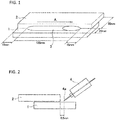
- FIG. 1 is a perspective view showing conditions of the gas-shielded arc welding using wires in Invention Examples and Comparative Examples
- FIG. 2 is a side view thereof.
- Two plate-shaped steel sheets 1, 2 each having a length of 150 mm, a width of 50 mm, and a thickness of 2.9 mm were stacked so as to be shifted by 20 mm in a width direction (route interval: 0 mm) horizontally, and a fillet portion which was formed between an upper surface of the lower steel sheet 1 and a side surface of the upper steel sheet 2 was subjected to horizontal fillet welding that was performed under the welding conditions shown in Table 2 below by using each of the wire for gas-shielded arc welding in Invention Examples and Comparative Examples.
- the welding started at a position that was 15 mm away from one ends of the steel sheets 1, 2 in a longitudinal direction, the welding proceeded in a direction of an arrow A at a distance of 120 mm, and then welding was ended at a position that was on the opposite side to the welding start position and was 15 mm away from the other ends of the steel sheets 1, 2 in the longitudinal direction, thereby forming a weld metal 3.
- an angle of a welding torch 4 was 45° relative to a direction vertical to the steel sheet 1, and a target position of a wire 4a was about 0.5 mm away from an end surface of the steel sheet 2 in the width direction.
- the slag adhesiveness was evaluated by beating, with a steel chisel, a surface of the weld metal after welding, and inspecting whether the slag fell.
- the slag adhesiveness was evaluated as A (good) in the case where the slag did not fall off from the surface of the weld metal, and was evaluated as B (poor) in the case where the slag was easily peeled off and fell off.
- a coating film was formed by the electrodeposition coating on a surface of a bonding member obtained by the welding, and then a cycle corrosion test was carried out in accordance with JIS K 5600-7-9 (2006) to evaluate the rust prevention as an index of the electrodeposition coatability.
- the rust prevention was evaluated as A (good) in the case where an area proportion of rust generated on the weld bead was 0% or more and less than 20% after 30 cycles of cycle corrosion tests, and was evaluated as B (poor) in the case where the area proportion of the rust was 20% or more.
- test pieces were not subjected to the cycle corrosion test, and the case where a thin slag was spread on the weld metal and the electrodeposition coatability was good was evaluated as A (good), and the case where the slag aggregated on the weld metal and the electrodeposition coatability was deteriorated was evaluated as B (poor).
- a cross section of the produced fillet weld portion was embedded in a resin, and a welded end portion on the lower sheet side was observed. The observation was performed at a magnification of 50 times.
- the case where the shape was particularly smooth was evaluated as "A”
- the case where the shape was smooth was evaluated as "B”
- the case where the shape was poor was evaluated as "C”.
- a weld metal was prepared for each wire, and a tensile strength (MPa) was determined by measuring a tensile load.
- the tensile test of the total weld metal was carried out by taking a tensile test piece A0 from a center of a test sheet, in accordance with JISZ3111:2015.
- each wire and evaluation results of each test are shown together in Table 1 below.
- the remainder of the chemical components of the wire is Fe and inevitable impurities, and the amount of each component in the wire is indicated by a content (mass%) relative to the total mass of the wire.
- the formula (1) is [Ti]/[Si]
- the formula (2) is (1000 ⁇ [S] ⁇ [O])/([S] + 0.3 ⁇ [N] + 0.5 ⁇ [O])
- the formula (3) is ([Si] + [Ti]/3)/([C]/2 + 2 ⁇ [Al]).
- "-" in the columns of Cr and Mo means that the content thereof is less than 0.01 mass%.
- the content of N in the wire was less than the lower limit of the range of the present invention, and thus the shape of the bead was poor and the strength was low.
- the content of N in the wire was less than the lower limit of the range of the present invention, and thus the shape of the bead was poor.
- the wire No. 16 whose strength was measured showed a low strength.
- the content of Si in the wire was more than the upper limit of the range of the present invention, and the content of N was less than the lower limit of the range of the present invention, and thus the slag adhesiveness was low, which resulted in poor rust prevention.
- each of the content of Ti and the content of N in the wire, and the value of the formula (1) was less than the lower limit of the range of the present invention, and thus the rust prevention was poor.
- the content of Si and the content of N in the wire were less than the lower limit of the range of the present invention, and thus the amount of spatter generation was large and the shape of the bead was poor.
- the content of N in the wire was less than the lower limit of the range of the present invention, and the value of the formula (1) was more than the upper limit of the range of the present invention. Therefore, the thickness of slag was large, the rust prevention was poor, the shape of the bead was poor, and the strength was low.
- each of the content of Mn and the content of Ti in the wire, and the value of the formula (1) was less than the lower limit of the range of the present invention, and thus the rust prevention was poor and the strength was low.
- the content of Si in the wire was more than the upper limit of the range of the present invention, and each of the content of Mn and the content of N was less than the lower limit of the range of the present invention. Therefore, the slag adhesiveness was low, the rust prevention was poor, and the strength was low.
- each of the content of Mn and the content of Ti in the wire, and the value of the formula (1) were less than the lower limit of the range of the present invention, and thus the slag adhesiveness was low and the rust prevention was poor.
- the content of N in the wire was more than the upper limit of the range of the present invention, and thus the shape of the bead was poor and the slag adhesiveness was low.
- the amount of spatter generated during welding is small, and a step such as removal of the slag after welding is unnecessary, and a weld portion having excellent electrodeposition coatability and a good shape of the bead can be obtained.
Landscapes
- Chemical & Material Sciences (AREA)
- Engineering & Computer Science (AREA)
- Mechanical Engineering (AREA)
- Materials Engineering (AREA)
- Metallurgy (AREA)
- Organic Chemistry (AREA)
- Physics & Mathematics (AREA)
- Plasma & Fusion (AREA)
- Nonmetallic Welding Materials (AREA)
- Arc Welding In General (AREA)
Abstract
Description
- The present invention relates to a wire for gas-shielded arc welding.
- In recent years, technical developments relating to improvements in fuel efficiency of automobiles and the like have been actively promoted due to the increase of demand levels of environmental performances. Examples of a method of improving the fuel efficiency of the automobiles and the like include improvements of efficiency of an internal combustion engine, hybridization of an internal combustion engine, and electrification of an internal combustion engine. Since the weight of the vehicle body tends to be increased due to the mounting of a battery in the case of electrification, the development of a lightweight technology has been also advanced. For example, attempts of reducing the weight of a vehicle by using a thin steel sheet having a strength higher than a steel sheet in the related art to reduce the thickness of the vehicle have been actively promoted.
- Since underbody parts are exposed to a corrosive environment due to salt damage contained in moisture or snow melting agents from a road surface, the local reduction in thickness of the steel sheet is a problem. Therefore, in order to realize a further reduction in the weight of the vehicle, there is also a need for a technology capable of preventing corrosion of the underbody parts as well as the need for underbody parts having sufficient strength and durability even when the thickness of the steel sheet is reduced.
- In general, a method of electrodeposition coating after arc welding is adopted as a method of protecting underbody parts from a corrosive environment. However, when the electrodeposition coating is performed after the welding, an electrodeposition coating film is not formed on a weld slag, resulting in a coating defect, and a problem of corrosion progressing from this defect has occurred. Therefore, welding defects are prevented by increasing the thickness of the electrodeposition coating film, but the coating film may peel off together with a slag portion due to the force applied during traveling, and corrosion may be progressed from a part from which the coating film peels off, even if the coating film is formed on the slag.
- In addition, regarding parts used in closer to a road surface and parts that are thinner among the underbody parts, a method of improving corrosion resistance based on a sacrificial anticorrosion effect of zinc by using a galvanized steel sheet, even when the coating film is peeled off is adopted as measures against the corrosion. However, zinc is vaporized in the weld portion by heat during arc welding, and thus the effect of improving the corrosion resistance in the weld bead cannot be sufficiently expected. Therefore, corrosion due to the poor coating on the welding slag may occur, or even when a coating film is formed, corrosion may occur due to the peeling of the slag during traveling.
- Here, for example,
Patent Literature 1 discloses a welding wire in which the contents of C, Si, and Mn are adjusted and a total content of one or two or more selected from Zr, Ti, and Al is adjusted to prevent degradation of durability of parts caused by not forming the coating film on a portion covered by the slag even when the electrodeposition coating is performed after welding.Patent Literature 1 discloses that the peeling property of the slag adhering to the weld portion after welding is excellent, and the slag can be easily peeled off. In recent years, a method of physically removing a slag after welding has been used for ensuring reliability, mainly for luxury cars. - Patent Literature 1:
JP S62-124095 A - However, when the wire described in
Patent Literature 1 is used, the number of production steps is increased and the production cost is increased because of the addition of a slag removal step. Further, during the arc welding, there is a demand for a wire with less spatter generation in consideration of workability or the like. - Further, in a weld joint such as a lap fillet, stress is likely to be concentrated due to discontinuity in the shape, and when the reduction in thickness also occurs at the part, it becomes a factor of fatigue fracture. Therefore, a toe of weld bead is also required to be smooth.
- The present invention has been made in view of the above-described situations, and an object of the present invention is to provide a wire for gas-shielded arc welding, by which the amount of spatter generated during welding is small, a step such as removal of the slag after welding is unnecessary, and a weld portion having excellent electrodeposition coatability and a good shape of the bead can be obtained.
- As a result of intensive studies to solve the above problems, the present inventors have found that excellent electrodeposition coatability can be obtained without removing slag after welding, by uniformly forming a thin slag on a weld portion. Specifically, by adjusting the contents of Si and Ti in the wire and appropriately controlling the balance of components, it is possible to reduce the amount of spatter generated during welding, achieve a good shape of a bead, and uniformly form a thin slag having high adhesiveness in the weld portion. Since the thin slag is present, it is possible to prevent defects from being generated in the coating film formed by the electrodeposition coating on the weld portion. The present inventors have also found that the shape of the bead can be improved particularly by controlling the content of N among the components in the wire.
- Although the mechanism by which a thin slag is uniformly formed after welding to form an electrodeposition coating film uniformly as a whole is not clear, it is presumed that the conductivity is different between the thin slag and the thick slag. In addition, the reason why the coating film peels off with the slag when an electrodeposition coating film with a large thickness is formed is presumed as follows: steps are formed on a surface of a part due to formation of the coating film on an uneven slag with a high peeling property, and the force is likely to be applied during the traveling.
- The present invention has been made based on these findings.
- The wire for gas-shielded arc welding in the present invention includes, based on a total mass of the wire:
- C: 0.01 mass% or more and 0.10 mass% or less;
- Si: 0.05 mass% or more and 0.55 mass% or less;
- Mn: 1.60 mass% or more and 2.40 mass% or less;
- Ti: 0.05 mass% or more and 0.25 mass% or less;
- Cu: 0.01 mass% or more and 0.30 mass% or less;
- S: 0.001 mass% or more and 0.020 mass% or less;
- N: 0.0045 mass% or more and 0.0150 mass% or less;
- Al: 0.10 mass% or less; and
- P: 0.025 mass% or less,
- with the remainder being Fe and inevitable impurities,
- and the following relationship is satisfied:

- wherein [Si] is the content of Si (mass%) based on the total mass of the wire and [Ti] is the content of Ti (mass%) based on the total mass of the wire.
- In one aspect of the wire for gas-shielded arc welding, the content of Si is preferably 0.25 mass% or less.
- In one aspect of the wire for gas-shielded arc welding, the content of Ti is preferably 0.12 mass% or more.
- In one aspect of the wire for gas-shielded arc welding, the wire preferably further includes at least one of Cr: 0.10 mass% or less and Mo: 0.10 mass% or less.
- In one aspect of the wire for gas-shielded arc welding, the following relationship is preferably satisfied:

- In the present invention, it is possible to provide a wire for gas-shielded arc welding, by which the amount of spatter generated during welding is small, a step such as removal of the slag after welding is unnecessary, and a weld portion having excellent electrodeposition coatability and a good shape of the bead can be obtained.
-
-
FIG. 1 is a perspective view showing conditions of gas-shielded arc welding. -
FIG. 2 is a side view showing conditions of the gas-shielded arc welding. - Hereinafter, embodiments for carrying out the present invention are described in detail. It should be noted that the present invention is not limited to the embodiments described below, and can be optionally changed without departing from the scope of the present invention. Hereinafter, the reason for the addition and the reason for the numerical limitation of the components contained in a wire for gas-shielded arc welding in the present embodiment are described in detail. In the following description, the amount of each component in the wire is defined by the content thereof relative to the total mass of the wire.
- C is a component having a deoxidizing action and an effect of increasing strength of weld metal. Since one-pass welding is applied in welding of a thin sheet, there is no possibility that the strength is reduced unlike the case of multilayer welding that accompanies reheating, and strength equal to or higher than that of the base metal can be obtained.
- If the content of C in the wire is less than 0.01 mass%, it is difficult to obtain a minimum strength required for a mild steel. Therefore, the content of C in the wire is 0.01 mass% or more, preferably 0.02 mass% or more, and more preferably 0.03 mass% or more, based on a total mass of the wire.
- On the other hand, if the content of C in the wire is more than 0.10 mass%, the deoxidizing action is increased, and the viscosity of droplets is increased, and thus spatter is likely to occur due to a short circuit. In addition, CO is generated in a vicinity of an arc due to a combination of C and oxygen, and thus spatter is likely to occur due to the explosion, and fume emission increases. Accordingly, the content of C is preferably small, as long as it is within a range at which the desired strength of the weld metal can be obtained. Therefore, the content of C in the wire is 0.10 mass% or less, preferably 0.09 mass% or less, and more preferably 0.08 mass% or less, based on the total mass of the wire.
- Si is a component having a deoxidizing action and having an effect of improving the shape of a weld bead. The content of Si in the wire is appropriately controlled, so that a shape of a welding end portion can be formed into a smooth shape of the bead.
- In addition, when an appropriate amount of Si is contained in the wire, the adhesiveness between a slag and a weld metal can be enhanced by the Si phase existing in the slag. As a result, rust prevention can also be improved. In addition, when the appropriate amount of Si is contained, the amount of spatter generated during welding is reduced. Therefore, the content of Si in the wire is 0.05 mass% or more based on the total mass of the wire, and since the spatter is likely to occur when the content of Si is small, the content of Si is preferably 0.10 mass% or more, more preferably 0.12 mass% or more, and still more preferably 0.15 mass%, based on the total mass of the wire.
- On the other hand, if the content of Si in the wire is more than 0.55 mass%, a slag formed by combining Si with oxygen is likely to aggregate and a thickness of the slag is increased. Accordingly, an electrodeposition coating film is less likely to be formed on a surface of the slag, and coating defects are generated. Therefore, the content of Si in the wire is 0.55 mass% or less, preferably 0.40 mass% or less, more preferably 0.35 mass% or less, still more preferably 0.30 mass% or less, and even more preferably 0.25 mass% or less, based on the total mass of the wire.
- Mn is an important component for ensuring the desired strength of the weld metal. In the wire in the present embodiment, since each of the content of C and the content of Si in the wire is limited to the specific range in order to improve the workability and the rust prevention of a weld portion, it is necessary to appropriately control the content of Mn in order to obtain a sufficient strength of the weld metal. Since MnO has conductivity higher than SiO2, a coating film is likely to be formed on the slag uniformly in the electrodeposition coating after welding when the content of MnO in the slag is high.
- If the content of Mn in the wire is less than 1.60 mass%, it is difficult to obtain sufficient strength of the weld metal, and the effect of forming a coating film on the slag cannot be sufficiently obtained. Therefore, the content of Mn in the wire is 1.60 mass% or more, preferably 1.65 mass% or more, more preferably 1.70 mass% or more, and still more preferably 1.80 mass% or more, based on the total mass of the wire.
- On the other hand, if the content of Mn in the wire is more than 2.40 mass%, the deoxidation proceeds excessively, and the amount of oxygen in a molten pool decreases. Accordingly, the viscosity and surface tension of the droplets becomes high, and the shape of the bead is impared. Therefore, the content of Mn in the wire is 2.40 mass% or less, preferably 2.30 mass% or less, more preferably 2.20 mass% or less, and still more preferably 2.10 mass% or less, based on the total mass of the wire.
- Cu has an effect of improving the rust prevention of the wire, and in terms of the lower limit, the content of Cu is 0.01 mass% or more. The content of Cu in the wire is preferably 0.05 mass% or more, more preferably 0.10 mass% or more, and still more preferably 0.15 mass% or more, based on the total mass of the wire. On the other hand, if the content of Cu is more than 0.30 mass%, the required cracking resistance cannot be obtained. Therefore, the content of Cu in the wire is preferably 0.25 mass% or less, and more preferably 0.20 mass% or less.
- Ti is one of the most important elements in the wire in the present embodiment and is a component having a deoxidizing action and an action of changing the physical properties of the slag. Although the mechanism related to the effect of Ti is not always clear, the present inventors have found the tendency that when in a composite slag made of Si, Mn, and Ti, the wire contains an appropriate amount of Ti, the composite slag covered by Ti is formed. Such a slag not only has electrodeposition coatability but also has good adhesiveness between the slag and the base metal, so that corrosion hardly proceeds.
- If the content of Ti in the wire is less than 0.05 mass%, it is difficult to obtain a desired state of the slag. Therefore, the content of Ti in the wire is 0.05 mass% or more, preferably 0.12 mass% or more, and more preferably 0.16 mass% or more, based on the total mass of the wire.
- On the other hand, if the content of Ti in the wire is more than 0.25 mass%, the deoxidation proceeds excessively, and the slag generation amount is excessively large. Thus, the shape of the bead is deteriorated due to increase in thickness of the slag and the deoxidizing action that proceeds excessively. Therefore, the content of Ti in the wire is 0.25 mass% or less, preferably 0.23 mass% or less, and more preferably 0.21 mass% or less, based on the total mass of the wire.
- Al is a component having a deoxidizing action and having an action of changing the physical properties of the slag. Al is an element that reduces the adhesiveness of the slag since Al has an effect of aggregating the slag. Therefore, the content of Al in the wire is 0.10 mass% or less, preferably 0.05 mass% or less, and more preferably 0.03 mass% or less, based on the total mass of the wire. In the case where Al is contained, the content of Al is preferably 0.001 mass% or more.
- P is an element that reduces the cracking resistance of the weld metal, and the smaller the content of P in the wire is, the more preferred it is.
- If the content of P in the wire is more than 0.025 mass%, the required cracking resistance cannot be obtained. Therefore, the content of P in the wire is 0.025 mass% or less, preferably 0.020 mass% or less, more preferably 0.015 mass% or less, and still more preferably 0.010 mass% or less, based on the total mass of the wire.
- S is an element having an effect of aggregating the slag and improving the shape of the weld bead. For example, when the content of S in the wire is changed in a state where the amount of slag is constant, the slag aggregates to increase the thickness with an increase in the content of S, so that the smaller the content of S is, the more preferable for the electrodeposition coatability is. On the other hand, the larger the content of S is, the more preferable for the shape of the weld bead is.
- If the content of S in the wire is less than 0.001 mass%, the shape of the weld bead is poor. Therefore, the content of S in the wire is 0.001 mass% or more, preferably 0.003 mass% or more, and more preferably 0.005 mass% or more, based on the total mass of the wire.
- On the other hand, if the content of S in the wire is more than 0.020 mass%, it is difficult to uniformly form a thin slag on the weld metal, and there is a possibility that the electrodeposition coating film is not formed or is peeled off with the slag. Therefore, the content of S in the wire is 0.020 mass% or less, preferably 0.015 mass% or less, and more preferably 0.010 mass% or less, based on the total mass of the wire.
- N is an element having an effect of improving the strength of the weld metal, reducing the surface tension of the weld metal, and improving the shape of the bead. Further, N improves the strength of the weld metal and improves fatigue resistance. If the content of N in the wire is less than 0.0045 mass%, the strength of the weld metal decreases and the surface tension is too high, and thus the shape of the bead is deteriorated. If the content of N in the wire is more than 0.0150 mass%, the surface tension of the molten metal is too low, the amount of spatter increases, and the shape of the bead is deteriorated. Further, the slag adhesiveness also deteriorates. Therefore, the content of N in the wire is 0.0045 mass% or more, preferably 0.0047 mass% or more, and more preferably 0.0055 mass% or more. The content of N may be 0.0065 mass% or more, 0.0075 mass% or more, 0.0085 mass% or more, and 0.0095 mass% or more. In addition, the content of N in the wire is 0.0150 mass% or less, more preferably 0.0130 mass% or less, and still more preferably 0.0110 mass% or less.
- O is not an essential component in the wire in the present embodiment, but the content of O is preferably in a range of 0.0010 mass% or more and 0.0050 mass% or less since O is an element that affects the generation amount of the slag, and has an effect of reducing the surface tension and improving the shape of the bead. When the content of O in the wire is 0.0010 mass% or more, the shape of the bead is improved. When the content of O in the wire is 0.0050 mass% or less, the amount of the slag during welding can be reduced. Therefore, the content of O in the wire is preferably 0.0010 mass% or more, more preferably 0.0015 mass% or more, still more preferably 0.0020 mass% or more, and even more preferably 0.0030 mass% or more. In addition, the content of O in the wire is preferably 0.0050 mass% or less, and more preferably 0.0040 mass% or less.
- Cr and Mo are not essential components in the wire of the present embodiment but may be contained in order to improve the strength. Either Cr or Mo may be contained in a range of Cr: 0.001 mass% or more and 0.10 mass% or less, or Mo: 0.001 mass% or more and 0.10 mass% or less. Both Cr and Mo may be contained in a range of Cr: 0.001 mass% or more and 0.10 mass% or less, and Mo: 0.001 mass% or more and 0.10 mass% or less.
- The remainder of the wire in the present embodiment is Fe and inevitable impurities. Examples of the inevitable impurities include Zr, Ni, Co, Li, Sn, Sb, Bi, B, As and the like.
- Further, the wire in the present embodiment may contain Ni, Co, B, and/or Sb in a range of Ni ≤ 0.10 mass%, Co ≤ 0.10 mass%, B ≤ 0.01 mass%, and Sb ≤ 0.01 mass%.
- A distribution state of the slag can be controlled by appropriately controlling the ratio of the content of Ti to the content of Si in the wire. When the generation of the slag in the molten pool during welding is observed, a state where a large number of fine slags are generated is observed. Therefore, a thin slag is assumed to be spread on the weld metal when the ratio of the content of Ti to the content of Si is appropriately controlled.
- In the case where the content of Si (mass%) based on the total mass of the wire is defined as [Si] and the content of Ti (mass%) based on the total mass of the wire is defined as [Ti], when the content of Si increases relative to the content of Ti, and the value obtained by the following formula (1) is less than 0.1, there is a possibility that the slag aggregates and the electrodeposition coating film is not formed or is peeled with the slag. Therefore, in order to reduce the thickness of the slag, it is necessary to set the value obtained by the following formula (1) to 0.1 or more, preferably 0.4 or more, and more preferably 1.0 or more.
- On the other hand, when the content of Ti is increased relative to the content of Si and the value obtained by the following formula (1) is more than 3.0, the generation amount of the slag is excessively increased, the thickness of slag is increased, and the shape of the bead is deteriorated. Therefore, the value obtained by the following formula (1) is required to be 3.0 or less, preferably 2.8 or less, and more preferably 2.5 or less.

- S, N, and O in the wire have an effect of decreasing the surface tension and improving the shape of the bead. However, since S aggregates the slag and O causes the amount of the slag to increase, it has been found that excessive addition of S or O may cause the electrodeposition coatability to deteriorate. As a result of intensive studies, the present inventors have found that a parameter whose variable is the contents of S, N, and O is controlled within the specific range, so that the shape of the bead can be more improved while maintaining good electrodeposition coatability. In the case where the content of S (mass%) based on the total mass of the wire is defined as [S], the content of O (mass%) based on the total mass of the wire is defined as [O], and the content of N (mass%) based on the total mass of the wire is defined as [N], when the value obtained by the following formula (2) is 0.7 or more and 3.0 or less, the electrodeposition coatability and the shape of the bead can be further improved. The value obtained by the following formula (2) is more preferably 1.0 or more. The value obtained by the following formula (2) is more preferably 2.5 or less.

- The amount of spatter generated during welding can be reduced by appropriately controlling a ratio of the content of Si and content of Ti to the content of C and content of Al in the wire. For example, when the droplet transfer behavior during pulsed arc welding was observed, a state where the detachment of the droplets was not satisfactory to cause a short circuit when the viscosity is too low, or a state where spatter was generated from the molten pool itself was observed. When the ratio of the content of Si and content of Ti to the content of C and content of Al is appropriately controlled, it is assumed that the droplets are easily detached and the amount of spatter is reduced by preventing an excessive decrease in the viscosity.
- In the case where the content of Si (mass%) based on the total mass of the wire is defined as [Si], the content of Ti (mass%) based on the total mass of the wire is defined as [Ti], the content of C (mass%) is defined as [C], and the content of Al (mass%) based on the total mass of the wire is defined as [Al], when a value obtained by the following formula (3) is 3 or more, the droplet detachment is good, the number of short circuits is appropriately maintained, and the welding with less spatter can be performed. Therefore, the value obtained by the following formula (3) is preferably 3 or more, more preferably 7 or more, and still more preferably 10 or more.

- In the case where welding is performed using the wire in the present embodiment, for example, Ar-CO2 mixed gas can be used as the shielding gas. When the Ar-CO2 mixed gas is used, the amount of the slag generated by oxidation decreases since the amount of oxygen contained in the shielding gas is small. As the ratio of the Ar-CO2 mixed gas, for example, 80 vol% of Ar-20 vol% of CO2 mixed gas or the like may be used.
- The welding posture using the wire in the present embodiment is not particularly limited. Further, the size (diameter) of the wire in the present embodiment is not particularly limited, and a wire having a diameter defined in accordance with a welding material standard such as AWS or JIS may be used.
- When the wire in the present embodiment is produced, the wire can be produced by a usual method without requiring a special production condition. For example, steel having the above components is melted to obtain an ingot. The ingot is subjected to hot forging or the like as necessary, and then hot rolling is performed and further cold drawing is performed to form a wire. The wire is annealed at a temperature of about 500°C to 900°C as necessary, subjected to copper plating after pickling, and further subjected to finishing drawing as necessary to have a target wire diameter. Thereafter, a lubricant is applied, as necessary, to form a wire for welding.
- Hereinafter, the effects of the present invention are specifically described with reference to Invention Examples and Comparative Examples, but the present invention is not limited thereto.
- A wire for the gas-shielded arc welding having a wire diameter of 1.2 mm was produced so as to have the contents of various chemical components in the wire, as shown in Table 1.
-
FIG. 1 is a perspective view showing conditions of the gas-shielded arc welding using wires in Invention Examples and Comparative Examples, andFIG. 2 is a side view thereof. Two plate-shapedsteel sheets lower steel sheet 1 and a side surface of theupper steel sheet 2 was subjected to horizontal fillet welding that was performed under the welding conditions shown in Table 2 below by using each of the wire for gas-shielded arc welding in Invention Examples and Comparative Examples. - The welding started at a position that was 15 mm away from one ends of the
steel sheets steel sheets weld metal 3. As shown inFIG. 2 , an angle of awelding torch 4 was 45° relative to a direction vertical to thesteel sheet 1, and a target position of awire 4a was about 0.5 mm away from an end surface of thesteel sheet 2 in the width direction. - The slag adhesiveness was evaluated by beating, with a steel chisel, a surface of the weld metal after welding, and inspecting whether the slag fell. The slag adhesiveness was evaluated as A (good) in the case where the slag did not fall off from the surface of the weld metal, and was evaluated as B (poor) in the case where the slag was easily peeled off and fell off.
- A coating film was formed by the electrodeposition coating on a surface of a bonding member obtained by the welding, and then a cycle corrosion test was carried out in accordance with JIS K 5600-7-9 (2006) to evaluate the rust prevention as an index of the electrodeposition coatability. The rust prevention was evaluated as A (good) in the case where an area proportion of rust generated on the weld bead was 0% or more and less than 20% after 30 cycles of cycle corrosion tests, and was evaluated as B (poor) in the case where the area proportion of the rust was 20% or more. Some of the test pieces were not subjected to the cycle corrosion test, and the case where a thin slag was spread on the weld metal and the electrodeposition coatability was good was evaluated as A (good), and the case where the slag aggregated on the weld metal and the electrodeposition coatability was deteriorated was evaluated as B (poor).
- A cross section of the produced fillet weld portion was embedded in a resin, and a welded end portion on the lower sheet side was observed. The observation was performed at a magnification of 50 times. The case where the shape was particularly smooth was evaluated as "A", the case where the shape was smooth was evaluated as "B", and the case where the shape was poor was evaluated as "C".
- A weld metal was prepared for each wire, and a tensile strength (MPa) was determined by measuring a tensile load. The tensile test of the total weld metal was carried out by taking a tensile test piece A0 from a center of a test sheet, in accordance with JISZ3111:2015.
- As a result of a sensory evaluation during pulsed arc welding, the case of particularly small amount of spatter was evaluated as "A", the case of small amount of spatter was evaluated as "B", the case of slightly small amount of spatter was evaluated as "C", and the case of many short circuits and large amount of spatter was evaluated as "D" (poor).
- The chemical components of each wire and evaluation results of each test are shown together in Table 1 below. The remainder of the chemical components of the wire is Fe and inevitable impurities, and the amount of each component in the wire is indicated by a content (mass%) relative to the total mass of the wire. In Table 1, the formula (1) is [Ti]/[Si], the formula (2) is (1000 × [S] × [O])/([S] + 0.3 × [N] + 0.5 × [O]), and the formula (3) is ([Si] + [Ti]/3)/([C]/2 + 2 × [Al]). In Table 1, "-" in the columns of Cr and Mo means that the content thereof is less than 0.01 mass%. Further, in the columns of the evaluation results, "-" means that the evaluation is not performed.


Table 2 Welding mode Pulsed arc MAG welding Welding current 200 A to 210 A Arc voltage 24 V Travel speed 800 mm/min Electrode extension 15 mm Shielding gas composition 80 vol% of Ar-20 vol% of CO2 Shielding gas flow rate 25 L/min - As shown in Table 1 above, regarding wire No. 1 to No. 11 that were Invention Examples, the components of the wires and the values obtained by the formula (1) were within the range of the present invention, the amount of spatter generated during welding was small. In addition, in these Invention Examples, the slag adhesiveness is good, an electrodeposition coating film could be formed in a good state without removing the slag, and as a result, excellent rust prevention could be obtained.
- In contrast, regarding the wire No. 12 that was Comparative Example, the content of N in the wire was less than the lower limit of the range of the present invention, and thus the shape of the bead was poor and the strength was low.
- Regarding the wire No. 13 and No. 16 that were Comparative Examples, the content of N in the wire was less than the lower limit of the range of the present invention, and thus the shape of the bead was poor. In addition, the wire No. 16 whose strength was measured showed a low strength.
- Regarding the wire No. 14 that was Comparative Example, the content of Si in the wire was more than the upper limit of the range of the present invention, and the content of N was less than the lower limit of the range of the present invention, and thus the slag adhesiveness was low, which resulted in poor rust prevention.
- Regarding the wire No. 15 that was Comparative Example, each of the content of Ti and the content of N in the wire, and the value of the formula (1) was less than the lower limit of the range of the present invention, and thus the rust prevention was poor.
- Regarding the wire No. 17 that was Comparative Example, the content of Si and the content of N in the wire were less than the lower limit of the range of the present invention, and thus the amount of spatter generation was large and the shape of the bead was poor.
- Regarding the wire No. 18 that was Comparative Example, the content of N in the wire was less than the lower limit of the range of the present invention, and the value of the formula (1) was more than the upper limit of the range of the present invention. Therefore, the thickness of slag was large, the rust prevention was poor, the shape of the bead was poor, and the strength was low.
- Regarding the wire No. 19 that was Comparative Example, each of the content of Mn and the content of Ti in the wire, and the value of the formula (1) was less than the lower limit of the range of the present invention, and thus the rust prevention was poor and the strength was low.
- Regarding the wire No. 20 that was Comparative Example, the content of Si in the wire was more than the upper limit of the range of the present invention, and each of the content of Mn and the content of N was less than the lower limit of the range of the present invention. Therefore, the slag adhesiveness was low, the rust prevention was poor, and the strength was low.
- Regarding the wire No. 21 that was Comparative Example, each of the content of Mn and the content of Ti in the wire, and the value of the formula (1) were less than the lower limit of the range of the present invention, and thus the slag adhesiveness was low and the rust prevention was poor.
- Regarding the wire No. 22 and No. 23 that were Comparative Examples, the content of N in the wire was more than the upper limit of the range of the present invention, and thus the shape of the bead was poor and the slag adhesiveness was low.
- As described in detail above, by using the wire for gas-shielded arc welding in the embodiment of the present invention, the amount of spatter generated during welding is small, and a step such as removal of the slag after welding is unnecessary, and a weld portion having excellent electrodeposition coatability and a good shape of the bead can be obtained.
-
- 1,2:
- Steel sheet
- 3:
- Weld metal
- 4:
- Welding torch
- 4a:
- Wire
Claims (5)
- A wire for gas-shielded arc welding, comprising, based on a total mass of the wire:C: 0.01 mass% or more and 0.10 mass% or less;Si: 0.05 mass% or more and 0.55 mass% or less;Mn: 1.60 mass% or more and 2.40 mass% or less;Ti: 0.05 mass% or more and 0.25 mass% or less;Cu: 0.01 mass% or more and 0.30 mass% or less;S: 0.001 mass% or more and 0.020 mass% or less;N: 0.0045 mass% or more and 0.0150 mass% or less;Al: 0.10 mass% or less; andP: 0.025 mass% or less,with the remainder being Fe and inevitable impurities,wherein the following relationship is satisfied:
 wherein [Si] is the content of Si (mass%) based on the total mass of the wire and [Ti] is the content of Ti (mass%) based on the total mass of the wire.
 - The wire for gas-shielded arc welding according to claim 1, wherein the content of Si is 0.25 mass% or less.
- The wire for gas-shielded arc welding according to claim 1 or 2, wherein the content of Ti is 0.12 mass% or more.
- The wire for gas-shielded arc welding according to any one of claims 1 to 3, further comprising at least one of Cr: 0.10 mass% or less and Mo: 0.10 mass% or less.
- The wire for gas-shielded arc welding according to any one of claims 1 to 4, wherein the following relationship is satisfied:

Applications Claiming Priority (2)
| Application Number | Priority Date | Filing Date | Title |
|---|---|---|---|
| JP2019202161 | 2019-11-07 | ||
| JP2019238958A JP6771638B1 (en) | 2019-11-07 | 2019-12-27 | Gas shield arc welding wire |
Publications (2)
| Publication Number | Publication Date |
|---|---|
| EP3819071A1 true EP3819071A1 (en) | 2021-05-12 |
| EP3819071B1 EP3819071B1 (en) | 2022-01-26 |
Family
ID=72829224
Family Applications (1)
| Application Number | Title | Priority Date | Filing Date |
|---|---|---|---|
| EP20172394.7A Active EP3819071B1 (en) | 2019-11-07 | 2020-04-30 | Wire for gas-shielded arc welding |
Country Status (13)
| Country | Link |
|---|---|
| US (1) | US11117223B2 (en) |
| EP (1) | EP3819071B1 (en) |
| JP (2) | JP6771638B1 (en) |
| KR (1) | KR102749727B1 (en) |
| CN (1) | CN114616072B (en) |
| AR (1) | AR118911A1 (en) |
| AT (1) | AT18291U1 (en) |
| CA (1) | CA3079735C (en) |
| CZ (1) | CZ35965U1 (en) |
| DE (1) | DE202020005709U1 (en) |
| MX (1) | MX394278B (en) |
| SK (1) | SK9562Y1 (en) |
| WO (1) | WO2021090519A1 (en) |
Cited By (2)
| Publication number | Priority date | Publication date | Assignee | Title |
|---|---|---|---|---|
| EP4368331A1 (en) * | 2022-11-04 | 2024-05-15 | Kabushiki Kaisha Kobe Seiko Sho (Kobe Steel, Ltd.) | Wire for gas-shielded arc welding |
| EP4461456A4 (en) * | 2022-06-16 | 2026-03-11 | Kiswel Ltd | Slightly slag-formed wire with excellent weldability |
Families Citing this family (7)
| Publication number | Priority date | Publication date | Assignee | Title |
|---|---|---|---|---|
| JP2022102850A (en) * | 2020-12-25 | 2022-07-07 | 日鉄溶接工業株式会社 | SOLID WIRE FOR GAS SHIELD ARC WELDING USED FOR WELD OF LOW Si STEEL, JOINTING METHOD OF LOW Si STEEL, AND REPAIR METHOD OF LOW Si STEEL |
| CN114507819A (en) * | 2022-01-28 | 2022-05-17 | 包头钢铁(集团)有限责任公司 | Production method of vehicle atmospheric corrosion resistant 500MPa grade welding wire steel |
| EP4570410A4 (en) * | 2022-10-31 | 2025-11-26 | Jfe Steel Corp | Arc welding process with lap fillet weld and method for producing a weld joint |
| CN115805389A (en) * | 2022-12-23 | 2023-03-17 | 天津市金桥焊材集团股份有限公司 | Gas protection solid welding wire suitable for being matched with sulfuric acid dew point corrosion resistant pipeline |
| KR102838554B1 (en) * | 2023-02-21 | 2025-07-29 | 주식회사 포스코 | Welded parts with excellent corrosion resistance and electrodeposition coating at welded joints |
| TWI851193B (en) * | 2023-05-09 | 2024-08-01 | 中國鋼鐵股份有限公司 | Welding wire and manufacturing method the same |
| WO2025187756A1 (en) * | 2024-03-08 | 2025-09-12 | 株式会社神戸製鋼所 | Welding wire, welding method, and method for manufacturing weld metal |
Citations (5)
| Publication number | Priority date | Publication date | Assignee | Title |
|---|---|---|---|---|
| JPS5832598A (en) * | 1981-08-21 | 1983-02-25 | Kawasaki Steel Corp | One or both-sided one-layer welding method for cryogenic steel |
| JPS62124095A (en) | 1985-11-22 | 1987-06-05 | Nissan Motor Co Ltd | Welding wire and welding method |
| JP2001129684A (en) * | 1999-11-02 | 2001-05-15 | Kawasaki Steel Corp | Pulsed CO2 welding steel wire |
| US20040140303A1 (en) * | 2002-01-31 | 2004-07-22 | Tokihiko Kataoka | Steel wire for carbon dioxide shielded arc welding and welding process using the same |
| JP2006289395A (en) * | 2005-04-07 | 2006-10-26 | Kobe Steel Ltd | Solid wire for gas shielded arc welding |
Family Cites Families (21)
| Publication number | Priority date | Publication date | Assignee | Title |
|---|---|---|---|---|
| JPH0811313B2 (en) * | 1986-07-01 | 1996-02-07 | 新日本製鐵株式会社 | TIG welding wire for Cr-Mo steel |
| JPS63157794A (en) * | 1986-12-22 | 1988-06-30 | Nippon Steel Corp | Steel wire for mag welding |
| JP3523917B2 (en) * | 1994-09-29 | 2004-04-26 | 大同特殊鋼株式会社 | Gas shielded arc welding method |
| JPH08103884A (en) * | 1994-10-03 | 1996-04-23 | Sumitomo Metal Ind Ltd | Steel wire for gas shield metal arc welding |
| JP2801161B2 (en) * | 1995-10-03 | 1998-09-21 | 株式会社神戸製鋼所 | Solid wire for pulse MAG welding |
| JP2000158182A (en) * | 1998-11-25 | 2000-06-13 | Kawasaki Steel Corp | Steel wire for gas shielded arc welding and method for producing the same |
| JP3718464B2 (en) * | 2000-09-04 | 2005-11-24 | 日鐵住金溶接工業株式会社 | Flux-cored wire for gas shielded arc welding |
| JP2004195542A (en) * | 2002-12-20 | 2004-07-15 | Jfe Steel Kk | Steel wire for gas shielded arc welding |
| JP4768310B2 (en) * | 2005-04-28 | 2011-09-07 | 株式会社神戸製鋼所 | Solid wire for gas shielded arc welding |
| JP5021953B2 (en) * | 2006-04-28 | 2012-09-12 | 株式会社神戸製鋼所 | Gas shielded arc welding solid wire for weathering steel and gas shielded arc welding method using the same |
| JP4839193B2 (en) * | 2006-12-01 | 2011-12-21 | 株式会社神戸製鋼所 | Solid wire |
| JP4896691B2 (en) * | 2006-12-07 | 2012-03-14 | 新日本製鐵株式会社 | Solid wire for gas shielded arc welding |
| CN101524796A (en) * | 2009-04-13 | 2009-09-09 | 金秋生 | 55kg high-strength steel plate special welding wire dedicated to mining machinery |
| JP5449110B2 (en) * | 2010-11-08 | 2014-03-19 | 日鐵住金溶接工業株式会社 | Solid wire for Ar-CO2 mixed gas shielded arc welding |
| CN104162748A (en) * | 2014-08-22 | 2014-11-26 | 首钢总公司 | Welding wire special for high-strength steel penstock submerged-arc welding |
| JP2017001094A (en) * | 2015-06-05 | 2017-01-05 | 株式会社神戸製鋼所 | Weld metal and welding structure |
| JP6486844B2 (en) * | 2016-01-28 | 2019-03-20 | 日鐵住金溶接工業株式会社 | Flux-cored wire for gas shielded arc welding |
| JP6739187B2 (en) * | 2016-02-22 | 2020-08-12 | 株式会社神戸製鋼所 | Ni-based alloy solid wire for welding and method for producing Ni-based alloy weld metal |
| JP2018039024A (en) * | 2016-09-06 | 2018-03-15 | 株式会社神戸製鋼所 | Flux-cored wire for gas shield arc welding, and weld metal |
| KR20190047388A (en) * | 2017-10-27 | 2019-05-08 | 현대종합금속 주식회사 | Extra low silicon welding consumable having excellent porosity resistance and electro coating, and weld metal |
| JP7006576B2 (en) * | 2017-12-19 | 2022-02-10 | 日本製鉄株式会社 | Solid wire for gas shielded arc welding |
-
2019
- 2019-12-27 JP JP2019238958A patent/JP6771638B1/en active Active
-
2020
- 2020-03-05 CN CN202080076484.1A patent/CN114616072B/en active Active
- 2020-03-05 KR KR1020227013334A patent/KR102749727B1/en active Active
- 2020-03-05 WO PCT/JP2020/009521 patent/WO2021090519A1/en not_active Ceased
- 2020-04-30 AT ATGM50251/2021U patent/AT18291U1/en unknown
- 2020-04-30 DE DE202020005709.6U patent/DE202020005709U1/en active Active
- 2020-04-30 EP EP20172394.7A patent/EP3819071B1/en active Active
- 2020-04-30 SK SK500962021U patent/SK9562Y1/en unknown
- 2020-05-04 CA CA3079735A patent/CA3079735C/en active Active
- 2020-05-11 AR ARP200101347A patent/AR118911A1/en active IP Right Grant
- 2020-05-22 US US16/882,398 patent/US11117223B2/en active Active
- 2020-07-13 MX MX2020004956A patent/MX394278B/en unknown
- 2020-10-13 JP JP2020172695A patent/JP7448458B2/en active Active
-
2021
- 2021-04-30 CZ CZ2021-39493U patent/CZ35965U1/en active Protection Beyond IP Right Term
Patent Citations (5)
| Publication number | Priority date | Publication date | Assignee | Title |
|---|---|---|---|---|
| JPS5832598A (en) * | 1981-08-21 | 1983-02-25 | Kawasaki Steel Corp | One or both-sided one-layer welding method for cryogenic steel |
| JPS62124095A (en) | 1985-11-22 | 1987-06-05 | Nissan Motor Co Ltd | Welding wire and welding method |
| JP2001129684A (en) * | 1999-11-02 | 2001-05-15 | Kawasaki Steel Corp | Pulsed CO2 welding steel wire |
| US20040140303A1 (en) * | 2002-01-31 | 2004-07-22 | Tokihiko Kataoka | Steel wire for carbon dioxide shielded arc welding and welding process using the same |
| JP2006289395A (en) * | 2005-04-07 | 2006-10-26 | Kobe Steel Ltd | Solid wire for gas shielded arc welding |
Cited By (2)
| Publication number | Priority date | Publication date | Assignee | Title |
|---|---|---|---|---|
| EP4461456A4 (en) * | 2022-06-16 | 2026-03-11 | Kiswel Ltd | Slightly slag-formed wire with excellent weldability |
| EP4368331A1 (en) * | 2022-11-04 | 2024-05-15 | Kabushiki Kaisha Kobe Seiko Sho (Kobe Steel, Ltd.) | Wire for gas-shielded arc welding |
Also Published As
| Publication number | Publication date |
|---|---|
| EP3819071B1 (en) | 2022-01-26 |
| JP6771638B1 (en) | 2020-10-21 |
| CA3079735A1 (en) | 2021-02-05 |
| MX394278B (en) | 2025-03-24 |
| BR112022007798A2 (en) | 2022-07-05 |
| MX2020004956A (en) | 2022-07-27 |
| KR102749727B1 (en) | 2025-01-06 |
| DE202020005709U1 (en) | 2022-02-21 |
| JP2021074777A (en) | 2021-05-20 |
| JP2021074770A (en) | 2021-05-20 |
| CN114616072B (en) | 2023-10-10 |
| SK9562Y1 (en) | 2022-07-13 |
| AR118911A1 (en) | 2021-11-10 |
| SK500962021U1 (en) | 2022-03-09 |
| KR20220064409A (en) | 2022-05-18 |
| JP7448458B2 (en) | 2024-03-12 |
| CA3079735C (en) | 2022-03-08 |
| AT18291U1 (en) | 2024-08-15 |
| CZ35965U1 (en) | 2022-04-26 |
| US20210138591A1 (en) | 2021-05-13 |
| US11117223B2 (en) | 2021-09-14 |
| CN114616072A (en) | 2022-06-10 |
| WO2021090519A1 (en) | 2021-05-14 |
Similar Documents
| Publication | Publication Date | Title |
|---|---|---|
| EP3819071B1 (en) | Wire for gas-shielded arc welding | |
| CN103415641B (en) | Hot-dip Zn-Al-Mg-based steel sheet and manufacturing method thereof | |
| JP7510049B2 (en) | Solid wire for gas shielded arc welding and method for manufacturing welded joint | |
| JP6102902B2 (en) | Cold-rolled steel sheet, manufacturing method thereof, high-strength hot-dip galvanized steel sheet, and high-strength galvannealed steel sheet | |
| EP4306253A1 (en) | Arc welded joint and arc welding method | |
| JP7587195B2 (en) | Welded joints | |
| CA3152503C (en) | Wire for gas-shielded arc welding | |
| EP4306255A1 (en) | Arc-welded joint and arc-welding method | |
| KR102933688B1 (en) | steel welded member | |
| JP7564227B2 (en) | Welding wire capable of producing giga-class welds, welded structure manufactured using the same, and welding method thereof | |
| JP7794724B2 (en) | Gas shielded arc welding wire | |
| JP2025511509A (en) | Low slag wire with excellent weldability | |
| EP4306254A1 (en) | Arc-welded joint and arc-welding method | |
| JP7791459B2 (en) | Welded joints | |
| BR112022007798B1 (en) | GAS SHIELDED ARC WELDING WIRE | |
| WO2025187756A1 (en) | Welding wire, welding method, and method for manufacturing weld metal |
Legal Events
| Date | Code | Title | Description |
|---|---|---|---|
| REG | Reference to a national code |
Ref country code: DE Ref legal event code: R138 Ref document number: 202020005709 Country of ref document: DE Free format text: GERMAN DOCUMENT NUMBER IS 602020001713 |
|
| PUAI | Public reference made under article 153(3) epc to a published international application that has entered the european phase |
Free format text: ORIGINAL CODE: 0009012 |
|
| STAA | Information on the status of an ep patent application or granted ep patent |
Free format text: STATUS: THE APPLICATION HAS BEEN PUBLISHED |
|
| AK | Designated contracting states |
Kind code of ref document: A1 Designated state(s): AL AT BE BG CH CY CZ DE DK EE ES FI FR GB GR HR HU IE IS IT LI LT LU LV MC MK MT NL NO PL PT RO RS SE SI SK SM TR |
|
| STAA | Information on the status of an ep patent application or granted ep patent |
Free format text: STATUS: REQUEST FOR EXAMINATION WAS MADE |
|
| 17P | Request for examination filed |
Effective date: 20210602 |
|
| RBV | Designated contracting states (corrected) |
Designated state(s): AL AT BE BG CH CY CZ DE DK EE ES FI FR GB GR HR HU IE IS IT LI LT LU LV MC MK MT NL NO PL PT RO RS SE SI SK SM TR |
|
| GRAP | Despatch of communication of intention to grant a patent |
Free format text: ORIGINAL CODE: EPIDOSNIGR1 |
|
| STAA | Information on the status of an ep patent application or granted ep patent |
Free format text: STATUS: GRANT OF PATENT IS INTENDED |
|
| RIC1 | Information provided on ipc code assigned before grant |
Ipc: B23K 35/30 20060101AFI20210726BHEP Ipc: B23K 35/02 20060101ALI20210726BHEP Ipc: C22C 38/00 20060101ALI20210726BHEP Ipc: C22C 38/02 20060101ALI20210726BHEP Ipc: C22C 38/04 20060101ALI20210726BHEP Ipc: C22C 38/12 20060101ALI20210726BHEP Ipc: C22C 38/14 20060101ALI20210726BHEP Ipc: C22C 38/16 20060101ALI20210726BHEP Ipc: C22C 38/20 20060101ALI20210726BHEP Ipc: C22C 38/28 20060101ALI20210726BHEP Ipc: C22C 38/38 20060101ALI20210726BHEP Ipc: C22C 38/06 20060101ALI20210726BHEP Ipc: B23K 9/16 20060101ALN20210726BHEP Ipc: B23K 103/04 20060101ALN20210726BHEP |
|
| RIC1 | Information provided on ipc code assigned before grant |
Ipc: B23K 103/04 20060101ALN20210803BHEP Ipc: B23K 9/16 20060101ALN20210803BHEP Ipc: C22C 38/06 20060101ALI20210803BHEP Ipc: C22C 38/38 20060101ALI20210803BHEP Ipc: C22C 38/28 20060101ALI20210803BHEP Ipc: C22C 38/20 20060101ALI20210803BHEP Ipc: C22C 38/16 20060101ALI20210803BHEP Ipc: C22C 38/14 20060101ALI20210803BHEP Ipc: C22C 38/12 20060101ALI20210803BHEP Ipc: C22C 38/04 20060101ALI20210803BHEP Ipc: C22C 38/02 20060101ALI20210803BHEP Ipc: C22C 38/00 20060101ALI20210803BHEP Ipc: B23K 35/02 20060101ALI20210803BHEP Ipc: B23K 35/30 20060101AFI20210803BHEP |
|
| INTG | Intention to grant announced |
Effective date: 20210817 |
|
| RIN1 | Information on inventor provided before grant (corrected) |
Inventor name: YOKOTA, YASUYUKI Inventor name: KINASHI, HIKARU Inventor name: IKAI, KAZUYA |
|
| GRAS | Grant fee paid |
Free format text: ORIGINAL CODE: EPIDOSNIGR3 |
|
| GRAA | (expected) grant |
Free format text: ORIGINAL CODE: 0009210 |
|
| STAA | Information on the status of an ep patent application or granted ep patent |
Free format text: STATUS: THE PATENT HAS BEEN GRANTED |
|
| AK | Designated contracting states |
Kind code of ref document: B1 Designated state(s): AL AT BE BG CH CY CZ DE DK EE ES FI FR GB GR HR HU IE IS IT LI LT LU LV MC MK MT NL NO PL PT RO RS SE SI SK SM TR |
|
| REG | Reference to a national code |
Ref country code: GB Ref legal event code: FG4D |
|
| REG | Reference to a national code |
Ref country code: CH Ref legal event code: EP |
|
| REG | Reference to a national code |
Ref country code: AT Ref legal event code: REF Ref document number: 1464881 Country of ref document: AT Kind code of ref document: T Effective date: 20220215 |
|
| REG | Reference to a national code |
Ref country code: IE Ref legal event code: FG4D |
|
| REG | Reference to a national code |
Ref country code: DE Ref legal event code: R096 Ref document number: 602020001713 Country of ref document: DE |
|
| REG | Reference to a national code |
Ref country code: SE Ref legal event code: TRGR |
|
| REG | Reference to a national code |
Ref country code: NO Ref legal event code: T2 Effective date: 20220126 |
|
| REG | Reference to a national code |
Ref country code: LT Ref legal event code: MG9D Ref country code: SK Ref legal event code: T3 Ref document number: E 39208 Country of ref document: SK |
|
| REG | Reference to a national code |
Ref country code: NL Ref legal event code: MP Effective date: 20220126 |
|
| PG25 | Lapsed in a contracting state [announced via postgrant information from national office to epo] |
Ref country code: NL Free format text: LAPSE BECAUSE OF FAILURE TO SUBMIT A TRANSLATION OF THE DESCRIPTION OR TO PAY THE FEE WITHIN THE PRESCRIBED TIME-LIMIT Effective date: 20220126 |
|
| PG25 | Lapsed in a contracting state [announced via postgrant information from national office to epo] |
Ref country code: RS Free format text: LAPSE BECAUSE OF FAILURE TO SUBMIT A TRANSLATION OF THE DESCRIPTION OR TO PAY THE FEE WITHIN THE PRESCRIBED TIME-LIMIT Effective date: 20220126 Ref country code: PT Free format text: LAPSE BECAUSE OF FAILURE TO SUBMIT A TRANSLATION OF THE DESCRIPTION OR TO PAY THE FEE WITHIN THE PRESCRIBED TIME-LIMIT Effective date: 20220526 Ref country code: LT Free format text: LAPSE BECAUSE OF FAILURE TO SUBMIT A TRANSLATION OF THE DESCRIPTION OR TO PAY THE FEE WITHIN THE PRESCRIBED TIME-LIMIT Effective date: 20220126 Ref country code: HR Free format text: LAPSE BECAUSE OF FAILURE TO SUBMIT A TRANSLATION OF THE DESCRIPTION OR TO PAY THE FEE WITHIN THE PRESCRIBED TIME-LIMIT Effective date: 20220126 Ref country code: ES Free format text: LAPSE BECAUSE OF FAILURE TO SUBMIT A TRANSLATION OF THE DESCRIPTION OR TO PAY THE FEE WITHIN THE PRESCRIBED TIME-LIMIT Effective date: 20220126 Ref country code: BG Free format text: LAPSE BECAUSE OF FAILURE TO SUBMIT A TRANSLATION OF THE DESCRIPTION OR TO PAY THE FEE WITHIN THE PRESCRIBED TIME-LIMIT Effective date: 20220426 |
|
| PG25 | Lapsed in a contracting state [announced via postgrant information from national office to epo] |
Ref country code: PL Free format text: LAPSE BECAUSE OF FAILURE TO SUBMIT A TRANSLATION OF THE DESCRIPTION OR TO PAY THE FEE WITHIN THE PRESCRIBED TIME-LIMIT Effective date: 20220126 Ref country code: LV Free format text: LAPSE BECAUSE OF FAILURE TO SUBMIT A TRANSLATION OF THE DESCRIPTION OR TO PAY THE FEE WITHIN THE PRESCRIBED TIME-LIMIT Effective date: 20220126 Ref country code: GR Free format text: LAPSE BECAUSE OF FAILURE TO SUBMIT A TRANSLATION OF THE DESCRIPTION OR TO PAY THE FEE WITHIN THE PRESCRIBED TIME-LIMIT Effective date: 20220427 Ref country code: FI Free format text: LAPSE BECAUSE OF FAILURE TO SUBMIT A TRANSLATION OF THE DESCRIPTION OR TO PAY THE FEE WITHIN THE PRESCRIBED TIME-LIMIT Effective date: 20220126 |
|
| PG25 | Lapsed in a contracting state [announced via postgrant information from national office to epo] |
Ref country code: IS Free format text: LAPSE BECAUSE OF FAILURE TO SUBMIT A TRANSLATION OF THE DESCRIPTION OR TO PAY THE FEE WITHIN THE PRESCRIBED TIME-LIMIT Effective date: 20220526 |
|
| REG | Reference to a national code |
Ref country code: DE Ref legal event code: R097 Ref document number: 602020001713 Country of ref document: DE |
|
| PG25 | Lapsed in a contracting state [announced via postgrant information from national office to epo] |
Ref country code: SM Free format text: LAPSE BECAUSE OF FAILURE TO SUBMIT A TRANSLATION OF THE DESCRIPTION OR TO PAY THE FEE WITHIN THE PRESCRIBED TIME-LIMIT Effective date: 20220126 Ref country code: RO Free format text: LAPSE BECAUSE OF FAILURE TO SUBMIT A TRANSLATION OF THE DESCRIPTION OR TO PAY THE FEE WITHIN THE PRESCRIBED TIME-LIMIT Effective date: 20220126 Ref country code: EE Free format text: LAPSE BECAUSE OF FAILURE TO SUBMIT A TRANSLATION OF THE DESCRIPTION OR TO PAY THE FEE WITHIN THE PRESCRIBED TIME-LIMIT Effective date: 20220126 Ref country code: DK Free format text: LAPSE BECAUSE OF FAILURE TO SUBMIT A TRANSLATION OF THE DESCRIPTION OR TO PAY THE FEE WITHIN THE PRESCRIBED TIME-LIMIT Effective date: 20220126 |
|
| PG25 | Lapsed in a contracting state [announced via postgrant information from national office to epo] |
Ref country code: AL Free format text: LAPSE BECAUSE OF FAILURE TO SUBMIT A TRANSLATION OF THE DESCRIPTION OR TO PAY THE FEE WITHIN THE PRESCRIBED TIME-LIMIT Effective date: 20220126 |
|
| PLBE | No opposition filed within time limit |
Free format text: ORIGINAL CODE: 0009261 |
|
| STAA | Information on the status of an ep patent application or granted ep patent |
Free format text: STATUS: NO OPPOSITION FILED WITHIN TIME LIMIT |
|
| 26N | No opposition filed |
Effective date: 20221027 |
|
| REG | Reference to a national code |
Ref country code: BE Ref legal event code: MM Effective date: 20220430 |
|
| PG25 | Lapsed in a contracting state [announced via postgrant information from national office to epo] |
Ref country code: MC Free format text: LAPSE BECAUSE OF FAILURE TO SUBMIT A TRANSLATION OF THE DESCRIPTION OR TO PAY THE FEE WITHIN THE PRESCRIBED TIME-LIMIT Effective date: 20220126 Ref country code: LU Free format text: LAPSE BECAUSE OF NON-PAYMENT OF DUE FEES Effective date: 20220430 |
|
| PG25 | Lapsed in a contracting state [announced via postgrant information from national office to epo] |
Ref country code: BE Free format text: LAPSE BECAUSE OF NON-PAYMENT OF DUE FEES Effective date: 20220430 |
|
| PG25 | Lapsed in a contracting state [announced via postgrant information from national office to epo] |
Ref country code: IE Free format text: LAPSE BECAUSE OF NON-PAYMENT OF DUE FEES Effective date: 20220430 |
|
| REG | Reference to a national code |
Ref country code: AT Ref legal event code: UEP Ref document number: 1464881 Country of ref document: AT Kind code of ref document: T Effective date: 20220126 |
|
| P01 | Opt-out of the competence of the unified patent court (upc) registered |
Effective date: 20230523 |
|
| REG | Reference to a national code |
Ref country code: CH Ref legal event code: PL |
|
| PG25 | Lapsed in a contracting state [announced via postgrant information from national office to epo] |
Ref country code: LI Free format text: LAPSE BECAUSE OF NON-PAYMENT OF DUE FEES Effective date: 20230430 Ref country code: CH Free format text: LAPSE BECAUSE OF NON-PAYMENT OF DUE FEES Effective date: 20230430 |
|
| PG25 | Lapsed in a contracting state [announced via postgrant information from national office to epo] |
Ref country code: MK Free format text: LAPSE BECAUSE OF FAILURE TO SUBMIT A TRANSLATION OF THE DESCRIPTION OR TO PAY THE FEE WITHIN THE PRESCRIBED TIME-LIMIT Effective date: 20220126 Ref country code: CY Free format text: LAPSE BECAUSE OF FAILURE TO SUBMIT A TRANSLATION OF THE DESCRIPTION OR TO PAY THE FEE WITHIN THE PRESCRIBED TIME-LIMIT Effective date: 20220126 |
|
| PG25 | Lapsed in a contracting state [announced via postgrant information from national office to epo] |
Ref country code: HU Free format text: LAPSE BECAUSE OF FAILURE TO SUBMIT A TRANSLATION OF THE DESCRIPTION OR TO PAY THE FEE WITHIN THE PRESCRIBED TIME-LIMIT; INVALID AB INITIO Effective date: 20200430 |
|
| PG25 | Lapsed in a contracting state [announced via postgrant information from national office to epo] |
Ref country code: MT Free format text: LAPSE BECAUSE OF FAILURE TO SUBMIT A TRANSLATION OF THE DESCRIPTION OR TO PAY THE FEE WITHIN THE PRESCRIBED TIME-LIMIT Effective date: 20220126 |
|
| PGFP | Annual fee paid to national office [announced via postgrant information from national office to epo] |
Ref country code: DE Payment date: 20250305 Year of fee payment: 6 |
|
| PGFP | Annual fee paid to national office [announced via postgrant information from national office to epo] |
Ref country code: NO Payment date: 20250409 Year of fee payment: 6 |
|
| PGFP | Annual fee paid to national office [announced via postgrant information from national office to epo] |
Ref country code: AT Payment date: 20250325 Year of fee payment: 6 |
|
| PGFP | Annual fee paid to national office [announced via postgrant information from national office to epo] |
Ref country code: TR Payment date: 20250424 Year of fee payment: 6 |
|
| PGFP | Annual fee paid to national office [announced via postgrant information from national office to epo] |
Ref country code: CZ Payment date: 20250423 Year of fee payment: 6 |
|
| PG25 | Lapsed in a contracting state [announced via postgrant information from national office to epo] |
Ref country code: SI Free format text: LAPSE BECAUSE OF FAILURE TO SUBMIT A TRANSLATION OF THE DESCRIPTION OR TO PAY THE FEE WITHIN THE PRESCRIBED TIME-LIMIT Effective date: 20220126 |
|
| PGFP | Annual fee paid to national office [announced via postgrant information from national office to epo] |
Ref country code: SE Payment date: 20260312 Year of fee payment: 7 |
|
| PGFP | Annual fee paid to national office [announced via postgrant information from national office to epo] |
Ref country code: GB Payment date: 20260313 Year of fee payment: 7 |
|
| PGFP | Annual fee paid to national office [announced via postgrant information from national office to epo] |
Ref country code: IT Payment date: 20260320 Year of fee payment: 7 |
|
| PGFP | Annual fee paid to national office [announced via postgrant information from national office to epo] |
Ref country code: FR Payment date: 20260309 Year of fee payment: 7 |
|
| PGFP | Annual fee paid to national office [announced via postgrant information from national office to epo] |
Ref country code: SK Payment date: 20260324 Year of fee payment: 7 |