EP3818574B1 - Pouchzelle und stack - Google Patents
Pouchzelle und stack Download PDFInfo
- Publication number
- EP3818574B1 EP3818574B1 EP19735517.5A EP19735517A EP3818574B1 EP 3818574 B1 EP3818574 B1 EP 3818574B1 EP 19735517 A EP19735517 A EP 19735517A EP 3818574 B1 EP3818574 B1 EP 3818574B1
- Authority
- EP
- European Patent Office
- Prior art keywords
- cell
- pouch
- connection element
- pouch cell
- negative
- Prior art date
- Legal status (The legal status is an assumption and is not a legal conclusion. Google has not performed a legal analysis and makes no representation as to the accuracy of the status listed.)
- Active
Links
Images




Classifications
-
- H—ELECTRICITY
- H01—ELECTRIC ELEMENTS
- H01M—PROCESSES OR MEANS, e.g. BATTERIES, FOR THE DIRECT CONVERSION OF CHEMICAL ENERGY INTO ELECTRICAL ENERGY
- H01M50/00—Constructional details or processes of manufacture of the non-active parts of electrochemical cells other than fuel cells, e.g. hybrid cells
- H01M50/10—Primary casings; Jackets or wrappings
- H01M50/102—Primary casings; Jackets or wrappings characterised by their shape or physical structure
- H01M50/105—Pouches or flexible bags
-
- H—ELECTRICITY
- H01—ELECTRIC ELEMENTS
- H01M—PROCESSES OR MEANS, e.g. BATTERIES, FOR THE DIRECT CONVERSION OF CHEMICAL ENERGY INTO ELECTRICAL ENERGY
- H01M50/00—Constructional details or processes of manufacture of the non-active parts of electrochemical cells other than fuel cells, e.g. hybrid cells
- H01M50/50—Current conducting connections for cells or batteries
- H01M50/543—Terminals
- H01M50/552—Terminals characterised by their shape
- H01M50/553—Terminals adapted for prismatic, pouch or rectangular cells
- H01M50/555—Window-shaped terminals
-
- H—ELECTRICITY
- H01—ELECTRIC ELEMENTS
- H01M—PROCESSES OR MEANS, e.g. BATTERIES, FOR THE DIRECT CONVERSION OF CHEMICAL ENERGY INTO ELECTRICAL ENERGY
- H01M50/00—Constructional details or processes of manufacture of the non-active parts of electrochemical cells other than fuel cells, e.g. hybrid cells
- H01M50/50—Current conducting connections for cells or batteries
- H01M50/502—Interconnectors for connecting terminals of adjacent batteries; Interconnectors for connecting cells outside a battery casing
- H01M50/503—Interconnectors for connecting terminals of adjacent batteries; Interconnectors for connecting cells outside a battery casing characterised by the shape of the interconnectors
-
- H—ELECTRICITY
- H01—ELECTRIC ELEMENTS
- H01M—PROCESSES OR MEANS, e.g. BATTERIES, FOR THE DIRECT CONVERSION OF CHEMICAL ENERGY INTO ELECTRICAL ENERGY
- H01M50/00—Constructional details or processes of manufacture of the non-active parts of electrochemical cells other than fuel cells, e.g. hybrid cells
- H01M50/50—Current conducting connections for cells or batteries
- H01M50/502—Interconnectors for connecting terminals of adjacent batteries; Interconnectors for connecting cells outside a battery casing
- H01M50/514—Methods for interconnecting adjacent batteries or cells
- H01M50/517—Methods for interconnecting adjacent batteries or cells by fixing means, e.g. screws, rivets or bolts
-
- H—ELECTRICITY
- H01—ELECTRIC ELEMENTS
- H01M—PROCESSES OR MEANS, e.g. BATTERIES, FOR THE DIRECT CONVERSION OF CHEMICAL ENERGY INTO ELECTRICAL ENERGY
- H01M50/00—Constructional details or processes of manufacture of the non-active parts of electrochemical cells other than fuel cells, e.g. hybrid cells
- H01M50/50—Current conducting connections for cells or batteries
- H01M50/543—Terminals
- H01M50/547—Terminals characterised by the disposition of the terminals on the cells
- H01M50/548—Terminals characterised by the disposition of the terminals on the cells on opposite sides of the cell
-
- H—ELECTRICITY
- H01—ELECTRIC ELEMENTS
- H01M—PROCESSES OR MEANS, e.g. BATTERIES, FOR THE DIRECT CONVERSION OF CHEMICAL ENERGY INTO ELECTRICAL ENERGY
- H01M50/00—Constructional details or processes of manufacture of the non-active parts of electrochemical cells other than fuel cells, e.g. hybrid cells
- H01M50/50—Current conducting connections for cells or batteries
- H01M50/543—Terminals
- H01M50/564—Terminals characterised by their manufacturing process
- H01M50/566—Terminals characterised by their manufacturing process by welding, soldering or brazing
-
- Y—GENERAL TAGGING OF NEW TECHNOLOGICAL DEVELOPMENTS; GENERAL TAGGING OF CROSS-SECTIONAL TECHNOLOGIES SPANNING OVER SEVERAL SECTIONS OF THE IPC; TECHNICAL SUBJECTS COVERED BY FORMER USPC CROSS-REFERENCE ART COLLECTIONS [XRACs] AND DIGESTS
- Y02—TECHNOLOGIES OR APPLICATIONS FOR MITIGATION OR ADAPTATION AGAINST CLIMATE CHANGE
- Y02E—REDUCTION OF GREENHOUSE GAS [GHG] EMISSIONS, RELATED TO ENERGY GENERATION, TRANSMISSION OR DISTRIBUTION
- Y02E60/00—Enabling technologies; Technologies with a potential or indirect contribution to GHG emissions mitigation
- Y02E60/10—Energy storage using batteries
Definitions
- the present invention relates to a pouch cell with a positive contact area and a negative contact area, via which the pouch cell can be electrically contacted and thus charged and discharged.
- the pouch cell is flat and has a cell top and a cell bottom opposite the cell top.
- the pouch cell preferably has a lithium-ion accumulator.
- Pouch cells of the type mentioned above are basically known from the state of the art, for example from US 2018/026294 A1 or EP 1 922 776 A1 .
- the present invention is based on the object of providing a pouch cell which promotes simple and safe contacting.
- the invention includes the realization that pouch cells of the prior art are difficult to handle in the mass production process, since their contact tabs are typically close to one another and the pouch cells can be short-circuited if handled carelessly. It was also recognized that pouch cells cannot currently be resistance welded due to their design for electrical contact. In the mass production process of battery packs or stacks with pouch cells, this leads to a high technical and financial outlay for automated systems that carry out the electrical contact of the individual pouch cells.
- the stack can also be referred to as a pile, a stack or an accumulation.
- a pouch cell is created whose positive contact area is located exclusively on the top side of the cell and whose negative contact area is located exclusively on the bottom side of the cell, or vice versa.
- the pouch cell according to the invention can advantageously be handled safely in a mass production process, ie any short circuits between pouch cells in a stack can be avoided.
- a stack with a plurality of pouch cells can be provided.
- Such a stack can be part of a battery pack for supplying an electric hand-held power tool.
- the invention also leads to the use of a stack with a plurality of pouch cells according to the invention for supplying an electric hand-held power tool.
- the invention includes the knowledge that battery packs for electric hand-held power tools are typically made exclusively from cylindrically shaped lithium-ion cells.
- the required discharge currents increase, meaning that the battery packs reach the maximum permissible level before discharging due to higher power losses and must be switched off for thermal reasons.
- the residual energy remaining in the battery pack is not available to users - or only after a cooling phase.
- pouch cells With a stack comprising a plurality of pouch cells contacted according to the invention, thermally induced shutdown of battery packs for electric hand-held power tools can be reduced. This is because pouch cells can now be used instead of conventional cylindrical lithium-ion cells. It was recognized that pouch cells have a lower electrical resistance due to their internal electrical structure and thus have less power loss at comparatively high discharge powers, which means that battery packs with such pouch cells can be operated either for longer or at higher powers.
- the plus contact area is designed as an electrical-mechanical plus connection element and/or the minus contact area is designed as an electrical-mechanical minus connection element.
- the plus connection element and/or the minus connection element can each be flat and designed for contacting by means of pressing or welding.
- a stack with a plurality of pouch cells can therefore be provided by the preferably flat contact areas of adjacent pouch cells abutting against one another.
- a connecting element can be represented, for example, by a weldable and conductive plastic, wherein welding can be carried out, for example, by means of thermal or ultrasonic welding.
- the plus connecting element and the minus connecting element are each designed as a plug connection element.
- the plus connecting element and the minus connecting element are preferably designed as plug connection elements of a complementary type.
- the plus connecting element can be designed as a male plug connection element and the minus connecting element as a female plug connection element, or vice versa.
- the plus connecting element designed as a plug connection element and the minus connecting element designed as a plug connection element form a plug connection in the sense of a trapezoidal slide guide or also in the sense of a trapezoidal dovetail guide, for example. It has proven to be advantageous if a plug direction of the plug connection elements is oriented parallel to the top and bottom of the cell.
- a plug connection between the plus connecting element and the minus connecting element can be designed to be reversible or irreversible.
- one plug connection element or both plug connection elements can have barbs, for example.
- the plus connecting element and/or the minus connecting element are each designed as screw connecting elements.
- Such screw connecting elements are preferably of a complementary type.
- Individual pouch cells of a stack can be screwed together or into one another using the screw connecting elements.
- Such contacting can also be designed to be reversible or irreversible.
- the screw connection elements are only electrically conductive in sections, so that electrical contact only occurs after or at the end of a mechanical contact.
- electrical contact is only made by cells that are screwed into or onto each other when the cells are completely screwed onto or into each other. This has the advantage that short circuits caused by incorrect contacts in the Mass production processes can be fundamentally excluded or at least significantly reduced.
- the pouch cell is electrically insulated outside the positive contact area and/or outside the negative contact area.
- the top side of the cell and/or the bottom side of the cell are essentially flat.
- a cell thickness is preferably less than a cell width and/or a cell depth.
- the connecting elements extend perpendicularly to the flat top side of the cell and/or perpendicularly to the flat bottom side of the cell.
- the connecting elements can protrude beyond the flat top side of the cell and/or the flat bottom side of the cell.
- the plus contact area and the minus contact area are led out of the pouch cell via loops or electrical lines running within the pouch cell.
- the plus contact area and/or the minus contact area can be made of metal, for example.
- the plus contact area and/or the minus contact area can consist of aluminum or comprise aluminum.
- the minus contact area is preferably designed as a metallic minus pole.
- a metallic minus pole can consist of nickel, for example, or comprise nickel. Such a design is possible alternatively or additionally for the plus contact area.
- the invention is also achieved by a stack with a plurality of pouch cells of the type described above, wherein the pouch cells are electrically contacted with one another via their respective connecting elements.
- a stack with a plurality of pouch cells of the type described above, wherein the pouch cells are electrically contacted with one another via their respective connecting elements.
- contacting is a series connection, wherein a positive contact area of a first pouch cell is electrically contacted with a negative contact area of an adjacent pouch cell.
- Such a stack can be further developed in a corresponding manner by the features described above with reference to the pouch cell.
- the invention also leads to the use of a stack of the type described above for supplying an electric hand-held power tool, wherein the stack is preferably arranged in a battery pack of the electric hand-held power tool.
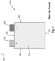
- a state-of-the-art pouch cell 100S is in Fig.1
- the pouch cell 100S has a plus contact area 10 and a minus contact area 20, via which the pouch cell 100S can be electrically contacted and thus charged and discharged.
- the pouch cell 100S is flat and has a cell top 110 and a cell bottom (not shown here) that is opposite the cell top 110.
- the plus contact area 10S and the minus contact area 20S are each designed as contact lugs that protrude from the pouch cell 100S in the lateral direction SR.
- the pouch cell 100S has a circumferential cell edge strip 130, on which the plus contact area 10S and the minus contact area 20S are located on at least one side.
- the pouch cell 100S shown has the disadvantage already mentioned at the beginning that it is comparatively difficult to handle in a mass production process due to the comparatively close proximity of the contact tabs (plus contact area 10S and minus contact area 20S), since - if handled carelessly - there is a risk of a short circuit in the pouch cell 100S.
- Fig.2 now a pouch cell 100 according to the invention.
- Fig. 2A the top and Fig. 2B the bottom of the pouch cell.
- the pouch cell 100 of the Fig.2 has a plus contact area 10 and a minus contact area 20, via which the pouch cell 100 is electrically contacted and can thus be charged and discharged.
- the pouch cell 100 is flat and has a cell top 110 ( Fig. 2A ).
- the pouch cell 100 also has a cell bottom 120 ( Fig. 2B ), which is opposite the cell top 110.
- the plus contact region 10 is located exclusively on the top side 110 of the cell and the minus contact region 20 is located exclusively on the bottom side 120 of the cell.
- the plus contact area 10 is designed as an electrical plus connection element 11 and the minus contact area 20 as an electrical minus connection element 21.
- the plus connection element 11 and the Minus connecting element 21 is each flat and, in this example, square.
- the plus connecting element 11 and the minus connecting element 21 are used to contact the pouch cell 100 by means of pressing.
- a stack 500 comprising a plurality of pressed pouch cells 100 is in Fig.3 shown. They show Fig. 3A and B different design variants of a stack 500 within a housing 510.
- FIG. 3A and B is common that a plurality of layered pouch cells 100 is provided, here, for example, six layered pouch cells 100.
- Each of the pouch cells 100 has a cell top 110 with a positive contact area 10 arranged thereon and a cell bottom 120 with a negative contact area 20 arranged thereon.
- the positive contact area 10 of a first pouch cell 100 is connected to the negative contact area 20 of an adjacent pouch cell.
- the pouch cell stacks 500 are series connections of pouch cells 100.
- Fig.3 It can be clearly seen that the respective pouch cells 100 are only electrically contacted on their cell top side 110 or cell bottom side 120.
- the topmost pouch cell 100 in the stack also has a plus stack connection 15.
- a minus stack connection 25 is provided on the bottommost pouch cell 100 in the stack.
- the stack 500 is electrically integrated into, for example, a battery pack for an electric hand-held power tool (not shown in detail here) via the plus stack connection 15 and the minus stack connection 25.
- Fig. 3A shows a housing 510 in a closed variant, i.e. the plus stack connection 15 and the minus stack connection 25 are not part of a surface of the housing 510. Electrical contact between the plus stack connection 15 and the minus stack connection 25 to the environment is made by electrical connecting lines not shown here.
- Fig. 3B the stack 500 in an open variant of the housing 510, i.e. the plus stack connection 15 and the minus stack connection 25 form part of the surface of the housing 510.
- the housing 510 of the Fig.3 can be cuboid-shaped, but they are preferably cube-shaped.
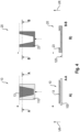
- Fig.4 shows sections of a second preferred embodiment of a pouch cell 100 according to the invention (see also Fig.5 ).
- the plus contact area 10 is designed as a combined electrical-mechanical plus plug connection element.
- the minus contact area 20 is designed as a combined electrical-mechanical minus plug connection element.
- the plug connection elements 13, 23 are of a complementary type and form a plug connection in the sense of a trapezoidal or wedge-shaped connection in the manner of a slide guide.
- Fig. 4A shows the plus contact area 10 in detail, with the upper part of the Fig. 4A a top view and in the lower part of the Fig. 4A a section according to the section line AA is shown. It can be clearly seen that the cell top 110 is essentially flat and the positive plug connection element 13 protrudes in the vertical direction VR over the flat cell top 110.
- Fig. B it can be clearly seen that the minus plug connection element 23 also protrudes in the vertical direction VR over a flat cell bottom side 120 indicated here.
- Fig.4 in any case represents a preferred embodiment.
- Fig.5 shows two pouch cells 100, 100' according to the second preferred embodiment of the Fig.4 before plugging them together.
- the pouch cells 100, 100' are therefore two pouch cells that would be adjacent in a stack not shown here.
- the two pouch cells 100, 100' of the Fig.5 are identical, whereby in the pouch cell 100 on the left side of the Fig.5 the cell top 110 is at the top, whereas on the right side of the Fig.5 a cell bottom side 120' of the second pouch cell 100' is shown facing upwards as an example.
- the plus plug connection element 13 of the first pouch cell 100 and the minus plug connection element 23' of the second pouch cell 100' are designed to complement each other.
- the plus plug connection element 13 is mechanically sealed with the minus plug connection element 23'. This mechanical sealing simultaneously creates electrical contact between the two pouch cells. Plugging together takes place in the plugging direction ST parallel to the top side 110 of the cell and the bottom side 120' of the cell.
- a thickness D of the pouch cell 100 is less than the width B and the length L of the pouch cell. In the exemplary embodiment shown here, the thickness D is less than one fifth of the width B and the length L.
- Fig.6 now shows a third preferred embodiment of a pouch cell 100 according to the invention in plan view ( Fig. 6A ) and in sub-view ( Fig. 6B ).
- the plus contact area 10 is designed as a plus screw connection element 17.
- the minus contact area 20 is designed as a minus screw connection element 27.
- the plus screw connection element 17 and minus screw connection element 27 are complementary type, as can be seen from the perspective side view of the Fig.7 As can be seen from the Fig. 7A
- the plus screw connection element 17 is designed as a male connection element.
- the minus screw connection element 27 ( Fig. 7B ) is designed as a female screw connection element.
- the cell top 110 and the cell bottom 120 are essentially flat and a peripheral cell edge strip 130 is free of any electrical contact elements.
- the plus screw connection element 17 and the minus screw connection element 27 are of a complementary type.
- the plus screw connection element 17 can be screwed into the minus screw connection element 27 (like a nut) like a screw.
- Fig.7 here shows, as an example, the top and bottom of one and the same pouch cell 100.
- Fig.7 Clearly visible in Fig.7 is also that the plus plug connection element 13 protrudes in the vertical direction VR beyond the flat cell top 110.
- the minus screw connection element 27 protrudes in the vertical direction VR beyond the cell bottom 120.
- the pouch cell 100 is electrically insulated. This is advantageously also a preferred development in all other embodiments.
- Fig.8 finally shows a fourth preferred embodiment of a pouch cell according to the invention.
- the pouch cell 100 has a plus contact area 10 on a cell top side 110 and a minus contact area 20 on an opposite cell bottom side 120.
- the plus contact area 10 is arranged exclusively on the cell top side 110 and the minus contact area 20 is arranged exclusively on the cell bottom side 120.
- the positive contact area 10 is designed as a male positive screw connection element 17 and the negative contact area 20 is designed as a female negative screw connection element 27.
- the minus screw connection element 27 extends only in sections over the cell underside 120 in the vertical direction VR.
- the minus screw connection element 27 is an electrical-mechanical connection element, i.e. the screw connection elements 17, 27 enable both electrical contact and mechanical connection of pouch cells to one another.
- the minus screw element 27 is designed in two parts, i.e. it has a purely mechanical area 27M and an electrical area 27E.
- the minus screw connection element 27 is only electrically conductive in sections, namely in the area 27E, so that electrical contact is only made when the plus screw connection element 17 is completely screwed into the minus screw connection element 27. Electrical contact is made via the electrical area 27E.
- the Fig.8 The variant shown has the advantage of further increased short-circuit safety for a mass production process of pouch cell stacks.
Landscapes
- Chemical & Material Sciences (AREA)
- Chemical Kinetics & Catalysis (AREA)
- Electrochemistry (AREA)
- General Chemical & Material Sciences (AREA)
- Engineering & Computer Science (AREA)
- Manufacturing & Machinery (AREA)
- Connection Of Batteries Or Terminals (AREA)
Description
- Die vorliegende Erfindung betrifft eine Pouchzelle mit einem Plus-Kontaktbereich und einem Minus-Kontaktbereich, über die die Pouchzelle elektrisch kontaktiert und so beladen und entladen werden kann. Die Pouchzelle ist flächig ausgebildet und weist eine Zelloberseite sowie eine der Zelloberseite gegenüberliegende eine Zellunterseite aufweist. Vorzugsweise weist die Pouchzelle einen Lithium-Ionen-Akkumulator auf.
- Pouchzellen der eingangs genannten Art sind grundsätzlich aus dem Stand der Technik bekannt, zum Beispiel aus
US 2018/026294 A1 oderEP 1 922 776 A1 . - Der vorliegenden Erfindung liegt die Aufgabe zugrunde, eine Pouchzelle bereitzustellen, die ein einfaches und sicheres Kontaktieren begünstigt.
- Die Aufgabe wird durch eine spezielle Ausbildung der Kontaktbereiche, gemäß Hauptanspruch 1, gelöst.
- Die Erfindung schließt die Erkenntnis ein, dass Pouchzellen des Standes der Technik im Massenproduktionsprozess schwierig zu handhaben sind, da ihre Kontaktfahnen typischerweise nahe beieinanderliegen und die Pouchzellen bei unachtsamer Handhabbarkeit kurzgeschlossen werden können. Weiterhin wurde erkannt, dass Pouchzellen aufgrund ihrer Bauform zur elektrischen Kontaktierung bisher nicht widerstandsgeschweißt werden können. Dies führt beim Massenproduktionsprozess von Akkupacks bzw. Stacks mit Pouchzellen zu einem hohen technischen und finanziellen Aufwand für automatisierte Anlagen, welche die elektrische Kontaktierung der einzelnen Pouchzellen durchführen. Der Stack kann auch als Stapel, Stoß oder Anhäufung bezeichnet werden.
- In Abkehr dazu wird eine Pouchzelle geschaffen, deren Plus-Kontaktbereich ausschließlich auf der Zelloberseite und deren Minus-Kontaktbereich ausschließlich auf der Zellunterseite, oder umgekehrt, befindlich ist. Dadurch kann die erfindungsgemäße Pouchzelle in einem Massenproduktionsprozess vorteilhafterweise unbedenklich gehandhabt werden, d.h. etwaige Kurschlüsse zwischen Pouchzellen eines Stacks können vermieden werden.
- Auf Basis der erfindungsgemäß bereitgestellten Pouchzelle kann ein Stack mit einer Mehrzahl von Pouchzellen bereitgestellt werden. Ein solcher Stack kann Teil eines Akkupacks zur Versorgung einer elektrischen Handwerkzeugmaschine sein. Demgemäß führt die Erfindung auch auf die Verwendung eines Stacks mit einer Mehrzahl erfindungsgemäßer Pouchzellen zur Versorgung einer elektrischen Handwerkzeugmaschine.
- Diesbezüglich schließt die Erfindung die Erkenntnis ein, dass Akkupacks für elektrische Handwerkzeugmaschinen typischerweise ausschließlich aus zylindrisch geformten Lithium-lonen-Zellen gefertigt sind. Mit zunehmender Leistungsanforderung von Handwerkzeugmaschinen steigen jedoch die erforderlichen Entladeströme, wodurch die Batteriepacks infolge höherer Verlustleistungen die maximale Zulässigkeit vor dem Entladen erreichen und thermisch bedingt abgeschaltet werden müssen. Die im Batteriepack verbleibende Restenergie steht Nutzern nicht - oder erst nach einer Abkühlphase - zur Verfügung.
- Mit einem Stack aufweisend eine Mehrzahl erfindungsgemäß kontaktierter Pouchzellen, kann ein thermisch bedingtes Abschalten von Batteriepacks für elektrische Handwerkzeugmaschinen reduziert werden. Dies da statt konventioneller zylindrisch geformter Lithium-lonen-Zellen nunmehr Pouchzellen eingesetzt werden können. Es wurde erkannt, dass Pouchzellen aufgrund ihres inneren elektrischen Aufbaus einen geringeren elektrischen Widerstand besitzen und somit bei vergleichsweise hohen Entladeleistungen weniger Verlustleistung aufweisen, wodurch Batteriepacks mit solchen Pouchzellen entweder länger oder mit höheren Leistungen betrieben werden können.
- In einer besonders bevorzugten Ausgestaltung ist der Plus-Kontaktbereich als elektrisch-mechanisches Plus-Verbindungselement und/oder der Minus-Kontaktbereich als elektrisch-mechanisches Minus-Verbindungselement ausgebildet. Das Plus-Verbindungselement und/oder das Minus-Verbindungselement können jeweils flach und zum Kontaktieren mittels Verpressens oder Verschweißens ausgebildet sein. Ein Stack mit einer Mehrzahl von Pouchzellen kann demnach dadurch bereitgestellt werden, dass die vorzugsweise flächig ausgebildeten Kontaktbereiche benachbarter Pouchzellen aneinander anliegen. Durch Aufeinanderpressen der einzelnen Pouchzellen in einem Akkupackgehäuse kann eine Kontaktierung der Einzelzellen gewährleistet werden. Durch ein solches Aufeinanderpressen der Einzelzellen wird vorzugsweise eine reversible Verbindung zwischen den jeweiligen Kontaktbereichen der geschichteten Pouchzellen erreicht. In einem alternativen Ausführungsbeispiel können die geschichteten Pouchzellen auch irreversibel miteinander verbunden sein. Dies kann beispielsweise dadurch geschehen, dass vor einem Aufeinanderpressen der Pouchzellen eine leitende Beschichtung, die dann einen jeweiligen Kontaktbereich bildet, aufgetragen wird, wobei die leitende Beschichtung eine Klebe- oder Haftwirkung aufweist. In einer weiteren Ausgestaltung kann ein Verbindungselement beispielsweise durch einen verschweißfähigen und leitfähigen Kunststoff dargestellt werden, wobei ein Verschweißen beispielsweise mittels thermischem oder Ultraschallschweißen erfolgen kann.
- Erfindungsgemäß ist das Plus-Verbindungselement und das Minus-Verbindungselement jeweils als Steckverbindungselement ausgebildet. Vorzugsweise sind das Plus-Verbindungselement und das Minus-Verbindungselement als Steckverbindungselemente komplementären Typs ausgestaltet. So kann beispielsweise das Plus-Verbindungselement als männliches Steckverbindungselement und das Minus-Verbindungselement als weibliches Steckverbindungselement, oder umgekehrt, ausgebildet sein. In einer besonders bevorzugten Ausgestaltung bilden das als Steckverbindungselement ausgebildete Plus-Verbindungselement und das als Steckverbindungselement ausgebildete Minus-Verbindungselement eine Steckverbindung im Sinne einer trapezförmigen Schlittenführung oder aber auch im beispielsweise im Sinne einer trapezförmigen Schwalbenschwanzführung. Es hat sich als vorteilhaft herausgestellt, wenn eine Steckrichtung der Steckverbindungselemente parallel zur Zelloberseite und zur Zellunterseite orientiert ist. Eine Steckverbindung zwischen Plus-Verbindungselement und Minus-Verbindungselement kann reversibel als auch irreversibel ausgebildet sein. Für eine irreversible Ausgestaltung kann ein Steckverbindungselement oder können beide Steckverbindungselemente beispielsweise über Widerhaken verfügen.
- In einer nicht erfindungsgemäßen Ausgestaltung sind das Plus-Verbindungselement und/oder das Minus-Verbindungselement jeweils als Schraubverbindungselemente ausgebildet. Vorzugsweise sind solche Schraubverbindungselemente vorzugsweise komplementären Typs. Mittels der Schraubverbindungselemente können einzelne Pouchzellen eines Stacks miteinander bzw. ineinander verschraubt werden. Auch eine solche Kontaktierung kann reversibel oder irreversibel ausgestaltet sein.
- Die Schraubverbindungselemente sind lediglich abschnittsweise elektrisch leitfähig, derart, dass ein elektrisches Kontaktieren erst nach einem oder am Ende eines mechanischen Kontaktierens erfolgt. Mit anderen Worten kann vorgesehen sein, dass durch ineinander bzw. aneinander zu schraubende Zellen eine elektrische Kontaktierung erst erfolgt, wenn die Zellen vollständig aneinander bzw. ineinander verschraubt sind. Dies hat den Vorteil, dass Kurzschlüsse durch falsche Kontaktierungen im Massenproduktionsprozess grundsätzlich ausgeschlossen oder zumindest aber deutlich vermindert werden können.
- Es hat sich als vorteilhaft herausgestellt, wenn die Pouchzelle außerhalb des Plus-Kontaktbereichs und/oder außerhalb des Minus-Kontaktbereichs elektrisch isoliert ist. In einer besonders bevorzugten Ausgestaltung ist die Zelloberseite und/oder die Zellunterseite im Wesentlichen flach ausgebildet. Eine Zelldicke ist vorzugsweise geringer als eine Zellbreite und/oder eine Zelltiefe.
- Es hat sich als vorteilhaft herausgestellt, wenn sich die Verbindungselemente jeweils senkrecht zur flachen Zelloberseite und/oder senkrecht zur flachen Zellunterseite erstrecken. Die Verbindungselemente können über die flache Zelloberseite und/oder die flache Zellunterseite hinausragen. In einer besonders bevorzugten Ausgestaltung ist der Plus-Kontaktbereich und der Minus-Kontaktbereich über innerhalb der Pouchzelle verlaufende Schleifen oder elektrische Leitungen aus der Pouchzelle herausgeführt.
- In allen hier beschriebenen Ausführungsbeispielen kann der Plus-Kontaktbereich und/oder der Minus-Kontaktbereich beispielsweise metallisch ausgebildet sein. Der Plus-Kontaktbereich und/oder der Minus-Kontaktbereich kann aus Aluminium bestehen oder Aluminium aufweisen. Der Minus-Kontaktbereich ist vorzugsweise als metallischer Minuspol ausgebildet. Ein metallischer Minuspol kann beispielsweise aus Nickel bestehen oder Nickel aufweisen. Eine solche Ausgestaltung ist alternativ oder zusätzlich für den Plus-Kontaktbereich möglich.
- Die Erfindung wird ebenfalls gelöst durch einen Stack mit einer Mehrzahl von Pouchzellen der vorbeschriebenen Art, wobei die Pouchzellen über ihre jeweiligen Verbindungselemente elektrisch miteinander kontaktiert sind. Vorzugsweise ist eine solche Kontaktierung eine Reihenschaltung, wobei ein Plus-Kontaktbereich einer ersten Pouchzelle mit einem Minus-Kontaktbereich einer benachbarten Pouchzelle elektrisch kontaktiert ist. Ein solcher Stack kann durch die mit Bezug auf die Pouchzelle vorbeschriebenen Merkmale in entsprechender Weise weitergebildet sein.
- Die Erfindung führt ebenfalls auf die Verwendung eines Stacks der vorbeschriebenen Art zur Versorgung einer elektrischen Handwerkzeugmaschine, wobei der Stack vorzugsweise in einem Akkupack der elektrischen Handwerkzeugmaschine angeordnet ist.
- Weitere Vorteile ergeben sich aus der folgenden Figurenbeschreibung. In den Figuren sind verschiedene Ausführungsbeispiele der vorliegenden Erfindung dargestellt. Die Figuren, die Beschreibung und die Ansprüche enthalten zahlreiche Merkmale in Kombination. Der Fachmann wird die Merkmale zweckmäßigerweise auch einzeln betrachten und zu sinnvollen weiteren Kombinationen zusammenfassen.
- In den Figuren sind gleiche und gleichartige Komponenten mit gleichen Bezugszeichen beziffert. Es zeigen:
- Fig. 1
- ein Pouchzelle des Standes der Technik;
- Fig. 2
- ein erstes bevorzugtes Ausführungsbeispiel einer erfindungsgemäßen Pouchzelle;
- Fig. 3
- ein bevorzugtes Ausführungsbeispiel eines erfindungsgemäßen Stacks;
- Fig. 4
- Steckverbindungselemente eines zweiten bevorzugten Ausführungsbeispiels einer erfindungsgemäßen Pouchzelle;
- Fig. 5
- zwei Pouchzellen des zweiten bevorzugten Ausführungsbeispiels in Gänze;
- Fig. 6
- ein drittes bevorzugtes Ausführungsbeispiel einer erfindungsgemäßen Pouchzelle in Draufsicht;
- Fig. 7
- das Ausführungsbeispiel der
Fig. 6 in perspektivischer Darstellung; und - Fig. 8
- ein viertes bevorzugtes Ausführungsbeispiel einer erfindungsgemäßen Pouchzelle.
- Eine Pouchzelle 100S des Standes der Technik ist in
Fig. 1 dargestellt. Die Pouchzelle 100S weist einen Plus-Kontaktbereich 10 und einen Minus-Kontaktbereich 20 auf, über die die Pouchzelle 100S elektrisch kontaktiert und so geladen und entladen werden kann. Die Pouchzelle 100S ist flächig ausgebildet und weist eine Zelloberseite 110 und eine hier nicht gezeigte Zellunterseite auf, die der Zelloberseite 110 gegenüberliegt. - Wie der
Fig. 1 entnommen werden kann, ist der Plus-Kontaktbereich 10S und der Minus-Kontaktbereich 20S jeweils als Kontaktfahne ausgebildet, die in seitlicher Richtung SR von der Pouchzelle 100S abstehen. Dabei weist die Pouchzelle 100S einen umlaufenden Zellrandstreifen 130 auf, an dem zumindest an einer Seite der Plus-Kontaktbereich 10S und der Minus-Kontaktbereich 20S befindlich ist. - Die in
Fig. 1 gezeigte Pouchzelle 100S hat den bereits eingangs genannten Nachteil, dass sie aufgrund der vergleichsweise dicht beieinanderliegenden Kontaktfahnen (Plus-Kontaktbereich 10S und Minus-Kontaktbereich 20S) in einem Massenproduktionsprozess vergleichsweise schwierig zu handhaben, da - bei unachtsamer Handhabung - ein Kurzschluss der Pouchzelle 100S droht. - In Abkehr zu der Pouchzelle 100S des Standes der Technik zeigt
Fig. 2 nunmehr eine erfindungsgemäße Pouchzelle 100. Dabei zeigtFig. 2A die Oberseite undFig. 2B die Unterseite der Pouchzelle. - Die Pouchzelle 100 der
Fig. 2 weist einen Plus-Kontaktbereich 10 und einen Minus-Kontaktbereich 20 auf, über die die Pouchzelle 100 elektrisch kontaktiert und so beladen und entladen werden kann. Die Pouchzelle 100 ist flächig ausgebildet und weist eine Zelloberseite 110 auf (Fig. 2A ). Die Pouchzelle 100 weist ebenfalls eine Zellunterseite 120 auf (Fig. 2B ), die der Zelloberseite 110 gegenüberliegt. - Erfindungsgemäß ist vorgesehen, dass der Plus-Kontaktbereich 10 ausschließlich auf der Zelloberseite 110 und der Minus-Kontaktbereich 20 ausschließlich auf der Zellunterseite 120 befindlich ist.
- Im ersten bevorzugten Ausführungsbeispiel der
Fig. 2 ist gut zu erkennen, dass ein umlaufender Zellrandstreifen 130 frei von jedweden elektrischen Kontaktierelementen ist. - Im Ausführungsbeispiel der
Fig. 2 ist der Plus-Kontaktbereich 10 als elektrisches Plus-Verbindungselement 11 und der Minus-Kontaktbereich 20 als elektrisches Minus-Verbindungselement 21 ausgebildet. Dabei sind das Plus-Verbindungselement 11 und das Minus-Verbindungselement 21 jeweils flach und hier beispielhaft quadratisch ausgebildet. Das Plus-Verbindungselement 11 und das Minus-Verbindungselement 21 dienen zum Kontaktieren der Pouchzelle 100 mittels Verpressens. - Ein Stack 500, der eine Mehrzahl verpresster Pouchzellen 100 aufweist, ist in
Fig. 3 dargestellt. Es zeigenFig. 3A und B verschiedene Ausgestaltungsvarianten eines Stacks 500 innerhalb eines Gehäuses 510. - Beiden
Figuren 3A und B ist gemein, dass eine Mehrzahl geschichteter Pouchzellen 100 vorgesehen ist, hier beispielhaft sechs geschichtete Pouchzellen 100. Jede der Pouchzellen 100 weist eine Zelloberseite 110 mit darauf angeordnetem Plus-Kontaktbereich 10 und eine Zellunterseite 120 mit darauf angeordnetem Minus-Kontaktbereich 20 auf. Dabei stehen Plus-Kontaktbereich 10 einer ersten Pouchzelle 100 mit dem Minus-Kontaktbereich 20 einer benachbarten Pouchzelle in Verbindung. Mit anderen Worten sind die Pouchzellenstacks 500 Reihenschaltungen von Pouchzellen 100. - Auch in
Fig. 3 ist gut zu erkennen, dass die jeweiligen Pouchzellen 100 lediglich auf ihrer Zelloberseite 110 bzw. Zellunterseite 120 elektrisch kontaktiert sind. - Die oberste Pouchzelle 100 im Stack weist zudem einen Plus-Stackanschluss 15 auf. Ein Minus-Stackanschluss 25 ist an der untersten Pouchzelle 100 im Stapel vorgesehen. Über den Plus-Stackanschluss 15 und den Minus-Stackanschluss 25 erfolgt eine elektrische Einbindung des Stacks 500 beispielsweise in einen hier nicht genauer dargestellten Akkupack für eine elektrische Handwerkzeugmaschine. Im Folgenden soll kurz auf die Unterschiede der Ausführungsbeispiele der
Fig. 3A und B eingegangen werden.Fig. 3A zeigt ein Gehäuse 510 in einer geschlossenen Variante, das heißt der Plus-Stackanschluss 15 und der Minus-Stackanschluss 25 sind nicht Teil einer Oberfläche des Gehäuses 510. Eine elektrische Kontaktierung des Plus-Stackanschlusses 15 bzw. des Minus-Stackanschlusses 25 zur Umgebung erfolgt durch hier nicht weiter dargestellte elektrische Verbindungsleitungen. - Im Gegensatz dazu zeigt
Fig. 3B den Stack 500 in einer offenen Variante des Gehäuses 510, das heißt der Plus-Stackanschluss 15 und der Minus-Stackanschluss 25 bilden einen Teil der Oberfläche des Gehäuses 510. - Die Gehäuse 510 der
Fig. 3 können quaderförmig ausgebildet sein, vorzugsweise sind diese aber würfelförmig ausgebildet. -
Fig. 4 zeigt Ausschnitte eines zweiten bevorzugten Ausführungsbeispiels einer erfindungsgemäßen Pouchzelle 100 (vgl. auchFig. 5 ). - In
Fig. 4 ist der Plus-Kontaktbereich 10 als kombiniertes elektrisch-mechanisches Plus-Steckverbindungselement ausgebildet. Der Minus-Kontaktbereich 20 ist als kombiniertes elektrisch-mechanisches Minus-Steckverbindungselement ausgebildet. Wie derFig. 4 in Zusammenschau entnommen werden kann, sind die Steckverbindungselemente 13, 23 komplementären Typs und bilden hier eine Steckverbindung im Sinne einer trapezförmigen oder keilförmigen Verbindung nach Art einer Schlittenführung. -
Fig. 4A zeigt den Plus-Kontaktbereich 10 im Detail, wobei im oberen Teil derFig. 4A eine Draufsicht und im unteren Teil derFig. 4A ein Schnitt gemäß der Schnittlinie A-A dargestellt ist. Gut zu erkennen ist, dass die Zelloberseite 110 im Wesentlichen flach ist und das Plus-Steckverbindungselement 13 in senkrechter Richtung VR über die flache Zelloberseite 110 absteht. - In Fig. B wiederum ist gut zu erkennen, dass auch das Minus-Steckverbindungselement 23 in senkrechter Richtung VR über eine hier angedeutete flache Zellunterseite 120 hinausragt. An dieser Stelle sei nochmals erwähnt, dass mehrere Möglichkeiten einer Ausgestaltung der Verbindungselemente als Steckverbindungselemente denkbar sind, wobei
Fig. 4 jedenfalls eine bevorzugte Ausgestaltung darstellt. -
Fig. 5 zeigt zwei Pouchzellen 100, 100' gemäß dem zweiten bevorzugten Ausführungsbeispiel derFig. 4 vor dem Zusammenstecken. Es handelt sich also bei den Pouchzellen 100, 100' um zwei Pouchzellen, die in einem hier nicht gezeigten Stack benachbart wären. - Die beiden Pouchzellen 100, 100' der
Fig. 5 sind identisch ausgebildet, wobei bei der Pouchzelle 100 auf der linken Seite derFig. 5 die Zelloberseite 110 oben liegt, wohingegen auf der rechten Seite derFig. 5 eine Zellunterseite 120' der zweiten Pouchzelle 100' beispielhaft nach oben dargestellt ist. - Wie der
Fig. 5 aufgrund der perspektivischen Darstellung gut zu entnehmen ist, sind das Plus-Steckverbindungselement 13 der ersten Pouchzelle 100 und das Minus-Steckverbindungselement 23' der zweiten Pouchzelle 100' zueinander komplementär ausgebildet. Im Zuge eines Zusammensteckens der beiden Pouchzellen 100, 100' - dies ist durch die gestrichelte Linie angedeutet - kommt es zu einem mechanischen Verschließen des Plus-Steckverbindungselements 13 mit dem Minus-Steckverbindungselement 23'. Durch dieses mechanische Verschließen wird gleichzeitig eine elektrische Kontaktierung der beiden Pouchzellen realisiert. Ein Zusammenstecken erfolgt dabei in Steckrichtung ST parallel zur Zelloberseite 110 und zur Zellunterseite 120'. - Wie ebenfalls aus Fig. Ersichtliche ist, ist eine Dicke D der Pouchzelle 100 geringer als die Breite B und die Länge L der Pouchzelle. Im vorliegend dargestellten Ausführungsbeispiel ist die Dicke D geringer als ein Fünftel der Breite B und der Länge L.
-
Fig. 6 zeigt nunmehr ein drittes bevorzugtes Ausführungsbeispiel einer erfindungsgemäßen Pouchzelle 100 in Draufsicht (Fig. 6A ) sowie in Unteransicht (Fig. 6B ). Im Ausführungsbeispiel derFig. 6 ist der Plus-Kontaktbereich 10 als Plus-Schraubenverbindungselement 17 ausgebildet. Der Minus-Kontaktbereich 20 ist als Minus-Schraubverbindungselement 27 ausgebildet. Das Plus-Schraubenverbindungselement 17 Minus-Schraubverbindungselement 27 sind komplentären Typs, wie aus der perspektivischen Seitenansicht derFig. 7 ersichtlich wird. Wie aus derFig. 7A ersichtlich ist, ist das Plus-Schraubverbindungselement 17 als männliches Verbindungselement ausgebildet. Das Minus-Schraubverbindungselement 27 (Fig. 7B ) ist als weibliches Schraubverbindungselement ausgebildet. In beiden Ansichten gut zu erkennen ist, dass die Zelloberseite 110 und die Zellunterseite 120 im Wesentlichen flach sind und ein umlaufender Zellrandstreifen 130 frei von jedweden elektrischen Kontaktierelementen ist. - Das Plus-Schraubverbindungselement 17 und das Minus-Schraubverbindungselement 27 sind zueinander komplementären Typs. Mit anderen Worten kann das Plus-Schraubverbindungselement 17 nach Art einer Schraube in das Minus-Schraubverbindungselement 27 (nach Art einer Mutter) eingeschraubt werden. Selbstverständlich gilt dies für verschiedene Zellen gleicher Bauart, da
Fig. 7 hier beispielhaft die Oberseite und die Unterseite ein und derselben Pouchzelle 100 zeigt. - Gut zu erkennen in
Fig. 7 ist ebenfalls, dass das Plus-Steckverbindungselement 13 in senkrechter Richtung VR über die flache Zelloberseite 110 hinausragt. Das Minus-Schraubverbindungselement 27 ragt in senkrechter Richtung VR über die Zellunterseite 120 hinaus. Außerhalb des Plus-Kontaktbereichs 10 und außerhalb des Minus-Kontaktbereichs 20 ist die Pouchzelle 100 elektrisch isoliert. Dies ist vorteilhafterweise auch bei allen anderen Ausführungsbeispielen eine bevorzugte Weiterbildung. -
Fig. 8 zeigt schließlich ein viertes bevorzugtes Ausführungsbeispiel einer erfindungsgemäßen Pouchzelle. Die Pouchzelle 100 weist einen Plus-Kontaktbereich 10 auf einer Zelloberseite 110 und einen Minus-Kontaktbereich 20 auf einer gegenüberliegenden Zellunterseite 120 auf. Der Plus-Kontaktbereich 10 ist ausschließlich auf der Zelloberseite 110 und der Minus-Kontaktbereich 20 ist ausschließlich auf der Zellunterseite 120 angeordnet. - Der Plus-Kontaktbereich 10 ist als männliches Plus-Schraubverbindungselement 17 und der Minus-Kontaktbereich 20 als weibliches Minus-Schraubverbindungselement 27 ausgebildet.
- Im Gegensatz zu dem mit Bezug auf
Fig. 7 beschriebenen Ausführungsbeispiel erstreckt sich das Minus-Schraubverbindungselement 27 lediglich abschnittsweise über die Zellunterseite 120 in senkrechter Richtung VR ab. Wie auch bei dem Plus-Schraubverbindungselement 17 handelt es sich bei dem Minus-Schraubverbindungselement 27 um ein elektrisch-mechanisches Verbindungselement, das heißt die Schraubverbindungselemente 17, 27 ermöglichen sowohl ein elektrisches Kontaktieren als auch ein mechanisches Verbinden von Pouchzellen untereinander. - Im Unterschied zu dem mit Bezug auf
Fig. 7 beschriebenen Ausführungsbeispiel ist beim Ausführungsbeispiel derFig. 8 das Minus-Schraubelement 27 zweiteilig ausgebildet, das heißt es verfügt über einen rein mechanischen Bereich 27M und einen elektrischen Bereich 27E. Somit ist das Minus-Schraubverbindungselement 27 lediglich abschnittsweise elektrisch leitfähig, nämlich im Bereich 27E, sodass ein elektrisches Kontaktieren erst erfolgt, wenn das Plus-Schraubverbindungselement 17 vollständig im Minus-Schraubverbindungselement 27 eingeschraubt ist. Eine elektrische Kontaktierung erfolgt dabei über den elektrischen Bereich 27E. Die inFig. 8 gezeigte Variante hat den Vorteil einer weiter erhöhten Kurzschlusssicherheit für einen Massenproduktionsprozess von Pouchzellenstacks. -
- 10
- Plus-Kontaktbereich
- 11
- Plus-Verbindungselement
- 13
- Plus-Steckverbindungselement
- 15
- Plus-Stackanschluss
- 17
- Plus-Schraubverbindungselement
- 20
- Minus-Kontaktbereich
- 21
- Minus-Verbindungselement
- 23
- Minus-Steckverbindungselement
- 25
- Minus-Stackanschluss
- 27
- Minus-Schraubverbindungselement
- 27M
- mechanischer Bereich
- 27E
- elektrischer Bereich
- 100
- Pouchzelle
- 110
- Zelloberseite
- 120
- Zellunterseite
- 130
- Zellenrandstreifen
- 500
- Stack
- 510
- Gehäuse
- B
- Breite
- D
- Dicke
- L
- Länge
- PR
- parallele Richtung
- SR
- seitliche Richtung
- ST
- Steckrichtung
- VR
- senkrechte Richtung
Claims (12)
- Pouchzelle (100) mit einem Plus-Kontaktbereich (10) und einem Minus-Kontaktbereich (20), über die die Pouchzelle (100) elektrisch kontaktiert und so beladen und entladen werden kann, wobei die Pouchzelle (100) flächig ausgebildet ist und eine Zelloberseite (110) sowie eine der Zelloberseite (110) gegenüberliegende Zellunterseite (120) aufweist, wobei dass der Plus-Kontaktbereich (10) ausschließlich auf der Zelloberseite (110) und der Minus-Kontaktbereich (20) ausschließlich auf der Zellunterseite (120), oder umgekehrt, befindlich ist, wobei der Plus-Kontaktbereich (10) als elektrisches und/oder mechanisches Plus-Verbindungselement (11) und der Minus-Kontaktbereich (20) als elektrisches und/oder mechanisches Minus-Verbindungselement (21) ausgebildet ist und das Plus-Verbindungselement (11) und das Minus-Verbindungselement (21) jeweils als Steckverbindungselement (13, 23), vorzugsweise komplementären Typs, ausgebildet sind und das Plus-Verbindungselement (11) und das Minus-Verbindungselement (21) jeweils als Steckverbindungselement (13, 23), vorzugsweise komplementären Typs, ausgebildet sind und wobei eine Steckrichtung (ST) der Steckverbindungselemente (13, 23) parallel zur Zelloberseite (110) und zur Zellunterseite (120) orientiert ist.
- Pouchzelle (100) nach Anspruch 1,
dadurch gekennzeichnet, dass die Pouchzelle (100) einen umlaufenden Zellrandstreifen (130) aufweist, der frei von elektrischen Kontaktfahnen oder frei von jedweden elektrischen Kontaktierelementen ist. - Pouchzelle (100) nach Anspruch 1,
dadurch gekennzeichnet, dass das Plus-Verbindungselement (11) und das Minus-Verbindungselement (21) jeweils flach und zum Kontaktieren mittels Verpressens oder Verschweißens ausgebildet sind. - Pouchzelle (100) nach Anspruch 1,
dadurch gekennzeichnet, dass das Plus-Verbindungselement (11) und das Minus-Verbindungselement (21) jeweils als Schraubverbindungselemente (17, 27), vorzugsweise komplementären Typs, ausgebildet sind. - Pouchzelle (100) nach einem der vorangehenden Ansprüche,
dadurch gekennzeichnet, dass die Schraubverbindungselemente (17, 27) lediglich abschnittweise elektrisch leitfähig sind, derart, dass ein elektrisches Kontaktieren erst nach einem mechanischen Kontaktieren erfolgt. - Pouchzelle (100) nach einem der vorangehenden Ansprüche,
dadurch gekennzeichnet, dass die Pochzelle (100) außerhalb des Plus-Kontaktbereichs (10) und des Minus-Kontaktbereichs (20) elektrisch isoliert ist. - Pouchzelle (100) nach einem der vorangehenden Ansprüche,
dadurch gekennzeichnet, dass die Zelloberseite (110) und die Zellunterseite (120) im Wesentlichen flach sind. - Pouchzelle (100) nach einem der vorangehenden Ansprüche,
dadurch gekennzeichnet, dass sich die Verbindungselemente (11, 21; 13, 23; 17, 27) jeweils senkrecht (VR) zur flachen Zelloberseite (110) und/oder Zellunterseite (120) erstrecken. - Pouchzelle (100) nach einem der vorangehenden Ansprüche,
dadurch gekennzeichnet, dass die Verbindungselemente (11, 21; 13, 23; 17, 27) über die flache Zelloberseite (110) bzw. die flache Zellunterseite (120) hinausragen. - Pouchzelle (100) nach einem der vorangehenden Ansprüche,
dadurch gekennzeichnet, dass der Plus-Kontaktbereich (10) und der Minus-Kontaktbereich (20) über innerhalb der Pouchzelle (100) verlaufende Schleifen oder Leitungen aus der Pouchzelle (100) herausgeführt sind. - Stack (500) aufweisend eine Mehrzahl von Pouchzellen (100) nach einem der vorangehenden Ansprüche, wobei die Pouchzellen (100) über ihre jeweiligen Verbindungselemente elektrisch miteinander kontaktiert sind.
- Verwendung eines Stacks (500) nach Anspruch 11 zur Versorgung einer elektrischen Handwerkzeugmaschine.
Applications Claiming Priority (2)
| Application Number | Priority Date | Filing Date | Title |
|---|---|---|---|
| EP18181724.8A EP3591730A1 (de) | 2018-07-04 | 2018-07-04 | Pouchzelle und stack |
| PCT/EP2019/066987 WO2020007679A1 (de) | 2018-07-04 | 2019-06-26 | Pouchzelle und stack |
Publications (2)
| Publication Number | Publication Date |
|---|---|
| EP3818574A1 EP3818574A1 (de) | 2021-05-12 |
| EP3818574B1 true EP3818574B1 (de) | 2024-05-29 |
Family
ID=62873261
Family Applications (2)
| Application Number | Title | Priority Date | Filing Date |
|---|---|---|---|
| EP18181724.8A Withdrawn EP3591730A1 (de) | 2018-07-04 | 2018-07-04 | Pouchzelle und stack |
| EP19735517.5A Active EP3818574B1 (de) | 2018-07-04 | 2019-06-26 | Pouchzelle und stack |
Family Applications Before (1)
| Application Number | Title | Priority Date | Filing Date |
|---|---|---|---|
| EP18181724.8A Withdrawn EP3591730A1 (de) | 2018-07-04 | 2018-07-04 | Pouchzelle und stack |
Country Status (4)
| Country | Link |
|---|---|
| US (1) | US11664548B2 (de) |
| EP (2) | EP3591730A1 (de) |
| CN (1) | CN112424983B (de) |
| WO (1) | WO2020007679A1 (de) |
Families Citing this family (5)
| Publication number | Priority date | Publication date | Assignee | Title |
|---|---|---|---|---|
| EP3161899A4 (de) | 2014-06-30 | 2017-12-27 | Black & Decker Inc. | Batteriepack für schnurlose elektrowerkzeuge |
| US11522237B2 (en) * | 2020-02-06 | 2022-12-06 | Lenovo (Singapore) Pte. Ltd. | Heat control in battery pack stack |
| WO2021184044A1 (en) | 2020-03-10 | 2021-09-16 | Black & Decker Inc. | Cordless power tool system compatible with multiple battery packs |
| DE102021127862A1 (de) | 2021-10-26 | 2023-04-27 | Dr. Ing. H.C. F. Porsche Aktiengesellschaft | Kraftfahrzeug-Traktionsbatterie-Zelle |
| DE102021130412B3 (de) | 2021-11-22 | 2023-05-17 | Dr. Ing. H.C. F. Porsche Aktiengesellschaft | Kraftfahrzeug-Traktionsbatteriezellen-Anordnung |
Family Cites Families (9)
| Publication number | Priority date | Publication date | Assignee | Title |
|---|---|---|---|---|
| DE102005042169B4 (de) * | 2005-09-06 | 2014-04-03 | Dilo Trading Ag | Verwendung einer Anordnung von Lithium-Polymer-Batterien |
| KR101057881B1 (ko) | 2009-05-29 | 2011-08-19 | 주식회사 엘지화학 | 셀 모듈 어셈블리의 절연성 검사를 위한 지그 장치 |
| DE102015000735A1 (de) | 2015-01-21 | 2016-07-21 | Audi Ag | Verfahren zur Fertigung einer Pouchzelle |
| EP3118910B1 (de) | 2015-07-15 | 2022-03-30 | Carl Freudenberg KG | Aufnahmeelement für pouch-zellen |
| CN205211862U (zh) | 2015-11-23 | 2016-05-04 | 东莞新能德科技有限公司 | 软包电池模组 |
| DE102016213142A1 (de) | 2016-07-19 | 2018-01-25 | Robert Bosch Gmbh | Batteriezelle, Batteriemodul und Verfahren zur Herstellung |
| DE102016225184A1 (de) * | 2016-12-15 | 2018-06-21 | Robert Bosch Gmbh | Batteriemodul mit Batteriezellsystem und Umhüllung |
| GB2557990A (en) * | 2016-12-21 | 2018-07-04 | Oxis Energy Ltd | Battery |
| GB201713302D0 (en) * | 2017-08-18 | 2017-10-04 | Agm Batteries Ltd | Pouch battery or cell |
-
2018
- 2018-07-04 EP EP18181724.8A patent/EP3591730A1/de not_active Withdrawn
-
2019
- 2019-06-26 WO PCT/EP2019/066987 patent/WO2020007679A1/de not_active Ceased
- 2019-06-26 US US17/056,890 patent/US11664548B2/en active Active
- 2019-06-26 EP EP19735517.5A patent/EP3818574B1/de active Active
- 2019-06-26 CN CN201980038049.7A patent/CN112424983B/zh active Active
Also Published As
| Publication number | Publication date |
|---|---|
| EP3591730A1 (de) | 2020-01-08 |
| EP3818574A1 (de) | 2021-05-12 |
| CN112424983A (zh) | 2021-02-26 |
| CN112424983B (zh) | 2023-04-04 |
| US20210210825A1 (en) | 2021-07-08 |
| US11664548B2 (en) | 2023-05-30 |
| WO2020007679A1 (de) | 2020-01-09 |
Similar Documents
| Publication | Publication Date | Title |
|---|---|---|
| EP3811440B1 (de) | Pouchzelle und stack | |
| EP3818574A1 (de) | Pouchzelle und stack | |
| DE202023101354U1 (de) | Energiespeichergerät und stromverbrauchendes Gerät | |
| DE102013213550A1 (de) | Batteriezelle mit einem prismatischen oder zylindrischen Gehäuse, Batteriemodul sowie Kraftfahrzeug | |
| WO2011116807A1 (de) | Einzelzelle und batterie mit einer mehrzahl von einzelzellen | |
| DE102018214363A1 (de) | Stromschiene, stromschienenmodul und batteriepack | |
| EP2534715B1 (de) | Energiespeicheranordnung und energiespeichervorrichtung | |
| WO2013107491A1 (de) | Zellengehäuse für elektrochemische zellen zum aufbau eines elektrochemischen energiespeichers | |
| DE102015007615A1 (de) | Verbindungselement zur elektrischen Verschaltung von Einzelzellen, Zellblock und elektrische Batterie | |
| DE212009000142U1 (de) | Verbindugsstelle für Pole elektrischer Zellen | |
| EP2676281B1 (de) | Anordnung mit einem gehäuse | |
| DE102015110667B4 (de) | Zellenanordnung | |
| DE102013213540A1 (de) | Batterie mit einem Zellverbinder, Kraftfahrzeug mit der Batterie sowie Verfahren zur Herstellung der Batterie | |
| WO2019092072A1 (de) | Modulgehäuse für ein stapelbares batteriemodul, batteriemodul sowie batteriestapel | |
| DE102010050998A1 (de) | Batterie mit einem Zellverbund | |
| EP3063808B1 (de) | Elektrochemischer akkumulator | |
| DE102013225340B4 (de) | Batteriemodul mit einer Mehrzahl von Batteriezellen sowie Batteriesystem mit wenigstens einem solchen Batteriemodul | |
| EP2956976B1 (de) | Zellverbinder zum elektrisch leitfähigen kontaktieren einer mehrzahl von batteriezellterminals, verfahren zum herstellen eines solchen zellverbinders und batteriemodul mit wenigstens einem solchen zellverbinder | |
| DE102017220505B4 (de) | Anschlusselement zur mechanischen und elektrischen Verbindung mit einem Kontaktelement einer elektrischen Speicherzelle, insbesondere einer Kontaktfahne einer Pouch-Zelle, sowie elektrisches Speicherzellenmodul | |
| DE102013106206B4 (de) | Akkumulator und Verfahren zur Herstellung eines Akkumulators | |
| DE102014106414A1 (de) | Batteriepack und Verfahren zur Montage des Batteriepacks | |
| DE102010060374A1 (de) | Verbindungstechnik für Batterien, insbesondere für Lithium-Ionen-Batterien, und geeignetes Herstellungsverfahren für eine solche Verbindungstechnik | |
| WO2010094485A1 (de) | Galvanische zelle und kontaktelement zu ihrer kontaktierung | |
| DE102015224921A1 (de) | Lithiumionenzelle für einen Energiespeicher, Lithiumionenakkumulator | |
| EP4205224B1 (de) | Pouchzelle und stack |
Legal Events
| Date | Code | Title | Description |
|---|---|---|---|
| STAA | Information on the status of an ep patent application or granted ep patent |
Free format text: STATUS: UNKNOWN |
|
| STAA | Information on the status of an ep patent application or granted ep patent |
Free format text: STATUS: THE INTERNATIONAL PUBLICATION HAS BEEN MADE |
|
| PUAI | Public reference made under article 153(3) epc to a published international application that has entered the european phase |
Free format text: ORIGINAL CODE: 0009012 |
|
| STAA | Information on the status of an ep patent application or granted ep patent |
Free format text: STATUS: REQUEST FOR EXAMINATION WAS MADE |
|
| 17P | Request for examination filed |
Effective date: 20210204 |
|
| AK | Designated contracting states |
Kind code of ref document: A1 Designated state(s): AL AT BE BG CH CY CZ DE DK EE ES FI FR GB GR HR HU IE IS IT LI LT LU LV MC MK MT NL NO PL PT RO RS SE SI SK SM TR |
|
| DAV | Request for validation of the european patent (deleted) | ||
| DAX | Request for extension of the european patent (deleted) | ||
| REG | Reference to a national code |
Ref country code: DE Ref legal event code: R079 Free format text: PREVIOUS MAIN CLASS: H01M0002020000 Ipc: H01M0050503000 Ref country code: DE Ref legal event code: R079 Ref document number: 502019011370 Country of ref document: DE Free format text: PREVIOUS MAIN CLASS: H01M0002020000 Ipc: H01M0050503000 |
|
| GRAP | Despatch of communication of intention to grant a patent |
Free format text: ORIGINAL CODE: EPIDOSNIGR1 |
|
| STAA | Information on the status of an ep patent application or granted ep patent |
Free format text: STATUS: GRANT OF PATENT IS INTENDED |
|
| INTG | Intention to grant announced |
Effective date: 20240311 |
|
| RIC1 | Information provided on ipc code assigned before grant |
Ipc: H01M 50/566 20210101ALI20240223BHEP Ipc: H01M 50/555 20210101ALI20240223BHEP Ipc: H01M 50/548 20210101ALI20240223BHEP Ipc: H01M 50/517 20210101ALI20240223BHEP Ipc: H01M 50/503 20210101AFI20240223BHEP |
|
| GRAS | Grant fee paid |
Free format text: ORIGINAL CODE: EPIDOSNIGR3 |
|
| GRAA | (expected) grant |
Free format text: ORIGINAL CODE: 0009210 |
|
| STAA | Information on the status of an ep patent application or granted ep patent |
Free format text: STATUS: THE PATENT HAS BEEN GRANTED |
|
| AK | Designated contracting states |
Kind code of ref document: B1 Designated state(s): AL AT BE BG CH CY CZ DE DK EE ES FI FR GB GR HR HU IE IS IT LI LT LU LV MC MK MT NL NO PL PT RO RS SE SI SK SM TR |
|
| REG | Reference to a national code |
Ref country code: CH Ref legal event code: EP |
|
| REG | Reference to a national code |
Ref country code: IE Ref legal event code: FG4D Free format text: LANGUAGE OF EP DOCUMENT: GERMAN |
|
| REG | Reference to a national code |
Ref country code: DE Ref legal event code: R096 Ref document number: 502019011370 Country of ref document: DE |
|
| REG | Reference to a national code |
Ref country code: LT Ref legal event code: MG9D |
|
| REG | Reference to a national code |
Ref country code: NL Ref legal event code: MP Effective date: 20240529 |
|
| PG25 | Lapsed in a contracting state [announced via postgrant information from national office to epo] |
Ref country code: IS Free format text: LAPSE BECAUSE OF FAILURE TO SUBMIT A TRANSLATION OF THE DESCRIPTION OR TO PAY THE FEE WITHIN THE PRESCRIBED TIME-LIMIT Effective date: 20240929 |
|
| PG25 | Lapsed in a contracting state [announced via postgrant information from national office to epo] |
Ref country code: BG Free format text: LAPSE BECAUSE OF FAILURE TO SUBMIT A TRANSLATION OF THE DESCRIPTION OR TO PAY THE FEE WITHIN THE PRESCRIBED TIME-LIMIT Effective date: 20240529 |
|
| PG25 | Lapsed in a contracting state [announced via postgrant information from national office to epo] |
Ref country code: FI Free format text: LAPSE BECAUSE OF FAILURE TO SUBMIT A TRANSLATION OF THE DESCRIPTION OR TO PAY THE FEE WITHIN THE PRESCRIBED TIME-LIMIT Effective date: 20240529 Ref country code: HR Free format text: LAPSE BECAUSE OF FAILURE TO SUBMIT A TRANSLATION OF THE DESCRIPTION OR TO PAY THE FEE WITHIN THE PRESCRIBED TIME-LIMIT Effective date: 20240529 |
|
| PG25 | Lapsed in a contracting state [announced via postgrant information from national office to epo] |
Ref country code: GR Free format text: LAPSE BECAUSE OF FAILURE TO SUBMIT A TRANSLATION OF THE DESCRIPTION OR TO PAY THE FEE WITHIN THE PRESCRIBED TIME-LIMIT Effective date: 20240830 |
|
| PG25 | Lapsed in a contracting state [announced via postgrant information from national office to epo] |
Ref country code: ES Free format text: LAPSE BECAUSE OF FAILURE TO SUBMIT A TRANSLATION OF THE DESCRIPTION OR TO PAY THE FEE WITHIN THE PRESCRIBED TIME-LIMIT Effective date: 20240529 |
|
| PG25 | Lapsed in a contracting state [announced via postgrant information from national office to epo] |
Ref country code: PL Free format text: LAPSE BECAUSE OF FAILURE TO SUBMIT A TRANSLATION OF THE DESCRIPTION OR TO PAY THE FEE WITHIN THE PRESCRIBED TIME-LIMIT Effective date: 20240529 |
|
| PG25 | Lapsed in a contracting state [announced via postgrant information from national office to epo] |
Ref country code: LV Free format text: LAPSE BECAUSE OF FAILURE TO SUBMIT A TRANSLATION OF THE DESCRIPTION OR TO PAY THE FEE WITHIN THE PRESCRIBED TIME-LIMIT Effective date: 20240529 |
|
| PG25 | Lapsed in a contracting state [announced via postgrant information from national office to epo] |
Ref country code: PL Free format text: LAPSE BECAUSE OF FAILURE TO SUBMIT A TRANSLATION OF THE DESCRIPTION OR TO PAY THE FEE WITHIN THE PRESCRIBED TIME-LIMIT Effective date: 20240529 Ref country code: NO Free format text: LAPSE BECAUSE OF FAILURE TO SUBMIT A TRANSLATION OF THE DESCRIPTION OR TO PAY THE FEE WITHIN THE PRESCRIBED TIME-LIMIT Effective date: 20240829 Ref country code: LV Free format text: LAPSE BECAUSE OF FAILURE TO SUBMIT A TRANSLATION OF THE DESCRIPTION OR TO PAY THE FEE WITHIN THE PRESCRIBED TIME-LIMIT Effective date: 20240529 Ref country code: IS Free format text: LAPSE BECAUSE OF FAILURE TO SUBMIT A TRANSLATION OF THE DESCRIPTION OR TO PAY THE FEE WITHIN THE PRESCRIBED TIME-LIMIT Effective date: 20240929 Ref country code: HR Free format text: LAPSE BECAUSE OF FAILURE TO SUBMIT A TRANSLATION OF THE DESCRIPTION OR TO PAY THE FEE WITHIN THE PRESCRIBED TIME-LIMIT Effective date: 20240529 Ref country code: GR Free format text: LAPSE BECAUSE OF FAILURE TO SUBMIT A TRANSLATION OF THE DESCRIPTION OR TO PAY THE FEE WITHIN THE PRESCRIBED TIME-LIMIT Effective date: 20240830 Ref country code: FI Free format text: LAPSE BECAUSE OF FAILURE TO SUBMIT A TRANSLATION OF THE DESCRIPTION OR TO PAY THE FEE WITHIN THE PRESCRIBED TIME-LIMIT Effective date: 20240529 Ref country code: ES Free format text: LAPSE BECAUSE OF FAILURE TO SUBMIT A TRANSLATION OF THE DESCRIPTION OR TO PAY THE FEE WITHIN THE PRESCRIBED TIME-LIMIT Effective date: 20240529 Ref country code: BG Free format text: LAPSE BECAUSE OF FAILURE TO SUBMIT A TRANSLATION OF THE DESCRIPTION OR TO PAY THE FEE WITHIN THE PRESCRIBED TIME-LIMIT Effective date: 20240529 Ref country code: RS Free format text: LAPSE BECAUSE OF FAILURE TO SUBMIT A TRANSLATION OF THE DESCRIPTION OR TO PAY THE FEE WITHIN THE PRESCRIBED TIME-LIMIT Effective date: 20240829 |
|
| PG25 | Lapsed in a contracting state [announced via postgrant information from national office to epo] |
Ref country code: NL Free format text: LAPSE BECAUSE OF FAILURE TO SUBMIT A TRANSLATION OF THE DESCRIPTION OR TO PAY THE FEE WITHIN THE PRESCRIBED TIME-LIMIT Effective date: 20240529 |
|
| PG25 | Lapsed in a contracting state [announced via postgrant information from national office to epo] |
Ref country code: NL Free format text: LAPSE BECAUSE OF FAILURE TO SUBMIT A TRANSLATION OF THE DESCRIPTION OR TO PAY THE FEE WITHIN THE PRESCRIBED TIME-LIMIT Effective date: 20240529 |
|
| PG25 | Lapsed in a contracting state [announced via postgrant information from national office to epo] |
Ref country code: DK Free format text: LAPSE BECAUSE OF FAILURE TO SUBMIT A TRANSLATION OF THE DESCRIPTION OR TO PAY THE FEE WITHIN THE PRESCRIBED TIME-LIMIT Effective date: 20240529 |
|
| PG25 | Lapsed in a contracting state [announced via postgrant information from national office to epo] |
Ref country code: EE Free format text: LAPSE BECAUSE OF FAILURE TO SUBMIT A TRANSLATION OF THE DESCRIPTION OR TO PAY THE FEE WITHIN THE PRESCRIBED TIME-LIMIT Effective date: 20240529 |
|
| PG25 | Lapsed in a contracting state [announced via postgrant information from national office to epo] |
Ref country code: CZ Free format text: LAPSE BECAUSE OF FAILURE TO SUBMIT A TRANSLATION OF THE DESCRIPTION OR TO PAY THE FEE WITHIN THE PRESCRIBED TIME-LIMIT Effective date: 20240529 |
|
| PG25 | Lapsed in a contracting state [announced via postgrant information from national office to epo] |
Ref country code: RO Free format text: LAPSE BECAUSE OF FAILURE TO SUBMIT A TRANSLATION OF THE DESCRIPTION OR TO PAY THE FEE WITHIN THE PRESCRIBED TIME-LIMIT Effective date: 20240529 Ref country code: SK Free format text: LAPSE BECAUSE OF FAILURE TO SUBMIT A TRANSLATION OF THE DESCRIPTION OR TO PAY THE FEE WITHIN THE PRESCRIBED TIME-LIMIT Effective date: 20240529 |
|
| PG25 | Lapsed in a contracting state [announced via postgrant information from national office to epo] |
Ref country code: SM Free format text: LAPSE BECAUSE OF FAILURE TO SUBMIT A TRANSLATION OF THE DESCRIPTION OR TO PAY THE FEE WITHIN THE PRESCRIBED TIME-LIMIT Effective date: 20240529 |
|
| PG25 | Lapsed in a contracting state [announced via postgrant information from national office to epo] |
Ref country code: SM Free format text: LAPSE BECAUSE OF FAILURE TO SUBMIT A TRANSLATION OF THE DESCRIPTION OR TO PAY THE FEE WITHIN THE PRESCRIBED TIME-LIMIT Effective date: 20240529 Ref country code: SK Free format text: LAPSE BECAUSE OF FAILURE TO SUBMIT A TRANSLATION OF THE DESCRIPTION OR TO PAY THE FEE WITHIN THE PRESCRIBED TIME-LIMIT Effective date: 20240529 Ref country code: RO Free format text: LAPSE BECAUSE OF FAILURE TO SUBMIT A TRANSLATION OF THE DESCRIPTION OR TO PAY THE FEE WITHIN THE PRESCRIBED TIME-LIMIT Effective date: 20240529 Ref country code: EE Free format text: LAPSE BECAUSE OF FAILURE TO SUBMIT A TRANSLATION OF THE DESCRIPTION OR TO PAY THE FEE WITHIN THE PRESCRIBED TIME-LIMIT Effective date: 20240529 Ref country code: DK Free format text: LAPSE BECAUSE OF FAILURE TO SUBMIT A TRANSLATION OF THE DESCRIPTION OR TO PAY THE FEE WITHIN THE PRESCRIBED TIME-LIMIT Effective date: 20240529 Ref country code: CZ Free format text: LAPSE BECAUSE OF FAILURE TO SUBMIT A TRANSLATION OF THE DESCRIPTION OR TO PAY THE FEE WITHIN THE PRESCRIBED TIME-LIMIT Effective date: 20240529 |
|
| REG | Reference to a national code |
Ref country code: CH Ref legal event code: PL |
|
| PG25 | Lapsed in a contracting state [announced via postgrant information from national office to epo] |
Ref country code: IT Free format text: LAPSE BECAUSE OF FAILURE TO SUBMIT A TRANSLATION OF THE DESCRIPTION OR TO PAY THE FEE WITHIN THE PRESCRIBED TIME-LIMIT Effective date: 20240529 Ref country code: MC Free format text: LAPSE BECAUSE OF FAILURE TO SUBMIT A TRANSLATION OF THE DESCRIPTION OR TO PAY THE FEE WITHIN THE PRESCRIBED TIME-LIMIT Effective date: 20240529 |
|
| PG25 | Lapsed in a contracting state [announced via postgrant information from national office to epo] |
Ref country code: LU Free format text: LAPSE BECAUSE OF NON-PAYMENT OF DUE FEES Effective date: 20240626 |
|
| REG | Reference to a national code |
Ref country code: DE Ref legal event code: R097 Ref document number: 502019011370 Country of ref document: DE |
|
| PLBE | No opposition filed within time limit |
Free format text: ORIGINAL CODE: 0009261 |
|
| STAA | Information on the status of an ep patent application or granted ep patent |
Free format text: STATUS: NO OPPOSITION FILED WITHIN TIME LIMIT |
|
| PG25 | Lapsed in a contracting state [announced via postgrant information from national office to epo] |
Ref country code: IE Free format text: LAPSE BECAUSE OF NON-PAYMENT OF DUE FEES Effective date: 20240626 |
|
| PG25 | Lapsed in a contracting state [announced via postgrant information from national office to epo] |
Ref country code: CH Free format text: LAPSE BECAUSE OF NON-PAYMENT OF DUE FEES Effective date: 20240630 Ref country code: SI Free format text: LAPSE BECAUSE OF FAILURE TO SUBMIT A TRANSLATION OF THE DESCRIPTION OR TO PAY THE FEE WITHIN THE PRESCRIBED TIME-LIMIT Effective date: 20240529 Ref country code: BE Free format text: LAPSE BECAUSE OF NON-PAYMENT OF DUE FEES Effective date: 20240630 |
|
| REG | Reference to a national code |
Ref country code: BE Ref legal event code: MM Effective date: 20240630 |
|
| 26N | No opposition filed |
Effective date: 20250303 |
|
| PGFP | Annual fee paid to national office [announced via postgrant information from national office to epo] |
Ref country code: DE Payment date: 20250618 Year of fee payment: 7 |
|
| PGFP | Annual fee paid to national office [announced via postgrant information from national office to epo] |
Ref country code: GB Payment date: 20250618 Year of fee payment: 7 |
|
| PGFP | Annual fee paid to national office [announced via postgrant information from national office to epo] |
Ref country code: FR Payment date: 20250627 Year of fee payment: 7 |
|
| REG | Reference to a national code |
Ref country code: AT Ref legal event code: MM01 Ref document number: 1691419 Country of ref document: AT Kind code of ref document: T Effective date: 20240626 |
|
| PG25 | Lapsed in a contracting state [announced via postgrant information from national office to epo] |
Ref country code: SE Free format text: LAPSE BECAUSE OF FAILURE TO SUBMIT A TRANSLATION OF THE DESCRIPTION OR TO PAY THE FEE WITHIN THE PRESCRIBED TIME-LIMIT Effective date: 20240529 |
|
| PG25 | Lapsed in a contracting state [announced via postgrant information from national office to epo] |
Ref country code: PT Free format text: LAPSE BECAUSE OF NON-PAYMENT OF DUE FEES Effective date: 20240529 |
|
| PG25 | Lapsed in a contracting state [announced via postgrant information from national office to epo] |
Ref country code: AT Free format text: LAPSE BECAUSE OF NON-PAYMENT OF DUE FEES Effective date: 20240626 |
|
| PG25 | Lapsed in a contracting state [announced via postgrant information from national office to epo] |
Ref country code: CY Free format text: LAPSE BECAUSE OF FAILURE TO SUBMIT A TRANSLATION OF THE DESCRIPTION OR TO PAY THE FEE WITHIN THE PRESCRIBED TIME-LIMIT; INVALID AB INITIO Effective date: 20190626 |
|
| PG25 | Lapsed in a contracting state [announced via postgrant information from national office to epo] |
Ref country code: HU Free format text: LAPSE BECAUSE OF FAILURE TO SUBMIT A TRANSLATION OF THE DESCRIPTION OR TO PAY THE FEE WITHIN THE PRESCRIBED TIME-LIMIT; INVALID AB INITIO Effective date: 20190626 |