EP3817023A1 - Schaltung und elektronische vorrichtung zur erkennung vom ein- und ausschalten eines blitzschalters - Google Patents
Schaltung und elektronische vorrichtung zur erkennung vom ein- und ausschalten eines blitzschalters Download PDFInfo
- Publication number
- EP3817023A1 EP3817023A1 EP20152296.8A EP20152296A EP3817023A1 EP 3817023 A1 EP3817023 A1 EP 3817023A1 EP 20152296 A EP20152296 A EP 20152296A EP 3817023 A1 EP3817023 A1 EP 3817023A1
- Authority
- EP
- European Patent Office
- Prior art keywords
- detection
- flash switch
- module
- assembly
- transforming
- Prior art date
- Legal status (The legal status is an assumption and is not a legal conclusion. Google has not performed a legal analysis and makes no representation as to the accuracy of the status listed.)
- Pending
Links
Images

Classifications
-
- H—ELECTRICITY
- H01—ELECTRIC ELEMENTS
- H01H—ELECTRIC SWITCHES; RELAYS; SELECTORS; EMERGENCY PROTECTIVE DEVICES
- H01H9/00—Details of switching devices, not covered by groups H01H1/00 - H01H7/00
- H01H9/16—Indicators for switching condition, e.g. "on" or "off"
-
- G—PHYSICS
- G01—MEASURING; TESTING
- G01R—MEASURING ELECTRIC VARIABLES; MEASURING MAGNETIC VARIABLES
- G01R31/00—Arrangements for testing electric properties; Arrangements for locating electric faults; Arrangements for electrical testing characterised by what is being tested not provided for elsewhere
- G01R31/327—Testing of circuit interrupters, switches or circuit-breakers
- G01R31/3277—Testing of circuit interrupters, switches or circuit-breakers of low voltage devices, e.g. domestic or industrial devices, such as motor protections, relays, rotation switches
-
- G—PHYSICS
- G01—MEASURING; TESTING
- G01R—MEASURING ELECTRIC VARIABLES; MEASURING MAGNETIC VARIABLES
- G01R31/00—Arrangements for testing electric properties; Arrangements for locating electric faults; Arrangements for electrical testing characterised by what is being tested not provided for elsewhere
- G01R31/327—Testing of circuit interrupters, switches or circuit-breakers
-
- G—PHYSICS
- G01—MEASURING; TESTING
- G01R—MEASURING ELECTRIC VARIABLES; MEASURING MAGNETIC VARIABLES
- G01R15/00—Details of measuring arrangements of the types provided for in groups G01R17/00 - G01R29/00, G01R33/00 - G01R33/26 or G01R35/00
- G01R15/14—Adaptations providing voltage or current isolation, e.g. for high-voltage or high-current networks
- G01R15/18—Adaptations providing voltage or current isolation, e.g. for high-voltage or high-current networks using inductive devices, e.g. transformers
-
- G—PHYSICS
- G01—MEASURING; TESTING
- G01R—MEASURING ELECTRIC VARIABLES; MEASURING MAGNETIC VARIABLES
- G01R15/00—Details of measuring arrangements of the types provided for in groups G01R17/00 - G01R29/00, G01R33/00 - G01R33/26 or G01R35/00
- G01R15/14—Adaptations providing voltage or current isolation, e.g. for high-voltage or high-current networks
- G01R15/20—Adaptations providing voltage or current isolation, e.g. for high-voltage or high-current networks using galvano-magnetic devices, e.g. Hall-effect devices, i.e. measuring a magnetic field via the interaction between a current and a magnetic field, e.g. magneto resistive or Hall effect devices
- G01R15/202—Adaptations providing voltage or current isolation, e.g. for high-voltage or high-current networks using galvano-magnetic devices, e.g. Hall-effect devices, i.e. measuring a magnetic field via the interaction between a current and a magnetic field, e.g. magneto resistive or Hall effect devices using Hall-effect devices
-
- H—ELECTRICITY
- H02—GENERATION; CONVERSION OR DISTRIBUTION OF ELECTRIC POWER
- H02J—ELECTRIC POWER NETWORKS; CIRCUIT ARRANGEMENTS OR SYSTEMS FOR SUPPLYING OR DISTRIBUTING ELECTRIC POWER; SYSTEMS FOR STORING ELECTRIC ENERGY
- H02J7/00—Circuit arrangements for charging or discharging batteries or for supplying loads from batteries
- H02J7/34—Parallel operation in networks using both storage and other DC sources, e.g. providing buffering
-
- H—ELECTRICITY
- H02—GENERATION; CONVERSION OR DISTRIBUTION OF ELECTRIC POWER
- H02J—ELECTRIC POWER NETWORKS; CIRCUIT ARRANGEMENTS OR SYSTEMS FOR SUPPLYING OR DISTRIBUTING ELECTRIC POWER; SYSTEMS FOR STORING ELECTRIC ENERGY
- H02J9/00—Circuit arrangements for emergency or stand-by power supply, e.g. for emergency lighting
- H02J9/04—Circuit arrangements for emergency or stand-by power supply, e.g. for emergency lighting in which the distribution system is disconnected from the normal source and connected to a standby source
- H02J9/06—Circuit arrangements for emergency or stand-by power supply, e.g. for emergency lighting in which the distribution system is disconnected from the normal source and connected to a standby source with automatic change-over, e.g. UPS systems
- H02J9/061—Circuit arrangements for emergency or stand-by power supply, e.g. for emergency lighting in which the distribution system is disconnected from the normal source and connected to a standby source with automatic change-over, e.g. UPS systems for DC powered loads
-
- H—ELECTRICITY
- H02—GENERATION; CONVERSION OR DISTRIBUTION OF ELECTRIC POWER
- H02M—APPARATUS FOR CONVERSION BETWEEN AC AND AC, BETWEEN AC AND DC, OR BETWEEN DC AND DC, AND FOR USE WITH MAINS OR SIMILAR POWER SUPPLY SYSTEMS; CONVERSION OF DC OR AC INPUT POWER INTO SURGE OUTPUT POWER; CONTROL OR REGULATION THEREOF
- H02M1/00—Details of apparatus for conversion
- H02M1/42—Circuits or arrangements for compensating for or adjusting power factor in converters or inverters
- H02M1/4208—Arrangements for improving power factor of AC input
- H02M1/4233—Arrangements for improving power factor of AC input using a bridge converter comprising active switches
-
- H—ELECTRICITY
- H02—GENERATION; CONVERSION OR DISTRIBUTION OF ELECTRIC POWER
- H02M—APPARATUS FOR CONVERSION BETWEEN AC AND AC, BETWEEN AC AND DC, OR BETWEEN DC AND DC, AND FOR USE WITH MAINS OR SIMILAR POWER SUPPLY SYSTEMS; CONVERSION OF DC OR AC INPUT POWER INTO SURGE OUTPUT POWER; CONTROL OR REGULATION THEREOF
- H02M3/00—Conversion of DC power input into DC power output
- H02M3/02—Conversion of DC power input into DC power output without intermediate conversion into AC
- H02M3/04—Conversion of DC power input into DC power output without intermediate conversion into AC by static converters
- H02M3/10—Conversion of DC power input into DC power output without intermediate conversion into AC by static converters using discharge tubes with control electrode or semiconductor devices with control electrode
- H02M3/145—Conversion of DC power input into DC power output without intermediate conversion into AC by static converters using discharge tubes with control electrode or semiconductor devices with control electrode using devices of a triode or transistor type requiring continuous application of a control signal
- H02M3/155—Conversion of DC power input into DC power output without intermediate conversion into AC by static converters using discharge tubes with control electrode or semiconductor devices with control electrode using devices of a triode or transistor type requiring continuous application of a control signal using semiconductor devices only
- H02M3/156—Conversion of DC power input into DC power output without intermediate conversion into AC by static converters using discharge tubes with control electrode or semiconductor devices with control electrode using devices of a triode or transistor type requiring continuous application of a control signal using semiconductor devices only with automatic control of output voltage or current, e.g. switching regulators
-
- H—ELECTRICITY
- H02—GENERATION; CONVERSION OR DISTRIBUTION OF ELECTRIC POWER
- H02M—APPARATUS FOR CONVERSION BETWEEN AC AND AC, BETWEEN AC AND DC, OR BETWEEN DC AND DC, AND FOR USE WITH MAINS OR SIMILAR POWER SUPPLY SYSTEMS; CONVERSION OF DC OR AC INPUT POWER INTO SURGE OUTPUT POWER; CONTROL OR REGULATION THEREOF
- H02M7/00—Conversion of AC power input into DC power output; Conversion of DC power input into AC power output
- H02M7/02—Conversion of AC power input into DC power output without possibility of reversal
- H02M7/04—Conversion of AC power input into DC power output without possibility of reversal by static converters
- H02M7/06—Conversion of AC power input into DC power output without possibility of reversal by static converters using discharge tubes without control electrode or semiconductor devices without control electrode
- H02M7/068—Conversion of AC power input into DC power output without possibility of reversal by static converters using discharge tubes without control electrode or semiconductor devices without control electrode mounted on a transformer
-
- H—ELECTRICITY
- H05—ELECTRIC TECHNIQUES NOT OTHERWISE PROVIDED FOR
- H05B—ELECTRIC HEATING; ELECTRIC LIGHT SOURCES NOT OTHERWISE PROVIDED FOR; CIRCUIT ARRANGEMENTS FOR ELECTRIC LIGHT SOURCES, IN GENERAL
- H05B47/00—Circuit arrangements for operating light sources in general, i.e. where the type of light source is not relevant
- H05B47/10—Controlling the light source
- H05B47/175—Controlling the light source by remote control
-
- H—ELECTRICITY
- H01—ELECTRIC ELEMENTS
- H01H—ELECTRIC SWITCHES; RELAYS; SELECTORS; EMERGENCY PROTECTIVE DEVICES
- H01H2300/00—Orthogonal indexing scheme relating to electric switches, relays, selectors or emergency protective devices covered by H01H
- H01H2300/03—Application domotique, e.g. for house automation, bus connected switches, sensors, loads or intelligent wiring
-
- H—ELECTRICITY
- H01—ELECTRIC ELEMENTS
- H01H—ELECTRIC SWITCHES; RELAYS; SELECTORS; EMERGENCY PROTECTIVE DEVICES
- H01H9/00—Details of switching devices, not covered by groups H01H1/00 - H01H7/00
- H01H9/16—Indicators for switching condition, e.g. "on" or "off"
- H01H9/167—Circuits for remote indication
Definitions
- This disclosure relates to the technical field of flash switches, in particular to a flash switch on-off detection circuit and an electronic device.
- Flash switches are widely used in smart home equipment.
- a flash switch in a conventional state maintains connection with a power supply and communicates with an electrical load and, when being pressed by an external force, disconnects the power supply from the electrical load.
- the flash switch can quickly return to the conventional state after the external force is released.
- on-off state change of the flash switch is viewed as a trigger signal of the equipment for changing its working state.
- the on-off detection mode of the flash switch provided in the related technology has a poor detection effect, so that it is difficult to meet the needs of users.
- the invention provides a flash switch on-off detection circuit and an electronic device, to solve defects in the art.
- an on-off detection circuit for a flash switch includes an on-off detection module and a control module; wherein an input end of the on-off detection module is connected with a power supply through the flash switch, the on-off detection module being configured to acquire a digital signal as a detection level according to an electromagnetic signal generated by input current; and an input end of the control module is connected with an output end of the on-off detection module, to receive the detection level and determine an on-off state change of the flash switch according to the detection level.
- an electronic device includes a flash switch and an on-off detection circuit for the flash switch.
- the on-off detection circuit includes an on-off detection module and a control module; an input end of the on-off detection module is connected with a power supply through the flash switch, the on-off detection module being configured to acquire a digital signal as a detection level according to an electromagnetic signal generated by input current; and an input end of the control module is connected with an output end of the on-off detection module, to receive the detection level and determine an on-off state change of the flash switch according to the detection level.
- the on-off detection circuit for the flash switch and the electronic device provided by the present disclosure at least have the following beneficial effects.
- the on-off detection module acquires a digital signal as the detection level according to an electromagnetic signal generated by the input current. Furthermore, the control module determines the on-off state change of the flash switch according to the detection level.
- the control module directly determines the on-off state change of the flash switch according to the detection level, without transforming the signal form of the detection level, such that the detection accuracy can be improved.
- the circuit according to the embodiment of the present disclosure can be more accurate and reliable in detection, and can optimize the overall detection effect.
- connection and the like are not limited to physical or mechanical connection, but may include electrical connection, no matter whether direct or indirect.
- the singular forms “a,” “an,” and “the” as used in the present disclosure as well as the appended claims also refer to plural forms unless the contrary is expressly indicated by the context. It should be appreciated that the term “and/or” as used herein refers to any or all possible combination of one or more associated listed items.
- a controller samples electrical signals passing through the flash switch by using Analog-to-Digital Converter (ADC) technology, and further obtains digital signals, and the on-off state change of the flash switch is determined according to the digital signals.
- ADC Analog-to-Digital Converter
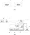
- FIG. 1 is a schematic diagram of a flash switch on-off detection circuit 100 according to an exemplary embodiment. As shown in FIG. 1 , the flash switch on-off detection circuit 100 includes an on-off detection module 110 and a control module 120.
- the on-off detection module 110 has an input end connected to a power supply 300 through a flash switch 200.
- the on-off detection module 110 acquires a detection level according to an electromagnetic signal generated by an input current.
- the detection level is a digital signal, for representing a use state of the flash switch 200.
- the use state of the flash switch 200 may be a static use state, for example connection or disconnection, and may also be a dynamic use state, for example, from connection to disconnection, or from disconnection to connection.
- the power supply 300 is an AC power supply
- an input current of the on-off detection module 110 is an AC electrical signal.
- the flash switch 200 When the flash switch 200 is in the switching-on state, the AC current electrical signal radiates a varying electromagnetic signal.
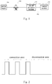
- the on-off detection module 110 outputs a first detection level, such as a square wave signal as shown in FIG. 2 under the connection state, according to the varying electromagnetic signal.
- the square wave signal includes a high level and a low level, and a frequency of switching the high level to the low level is the same as a frequency of inputting the AC electrical signal.
- the on-off detection module 100 When the flash switch 200 is in the switching-off state, the on-off detection module 100 does not input the current, while the on-off detection module 110 outputs a second detection level, such as a low level signal as shown in FIG. 2 under the disconnection state.
- the power supply 300 is a DC power supply.
- the input current of the on-off detection module 110 is a stable DC signal, and the input current radiates a stable electromagnetic signal.
- the on-off detection module 110 has no input current, so that there is no electromagnetic signal generated by the input current.
- the on-off detection module 110 outputs a third detection level, such as a low level signal.
- the input current of the on-off detection module 110 is a varying DC signal that radiates a varying electromagnetic signal.
- the on-off detection module 110 outputs a fourth detection level, such as a high level signal, according to the varying electromagnetic signal.
- control module 120 An input end of the control module 120 is connected to an output end of the on-off detection module 110, to receive the detection level. Furthermore, the control module 120 determines the on-off state change of the flash switch 200 directly according to the received detection level.
- control module 120 determines whether the currently received signal is a high level or a low level according to a preset level threshold, so as to determine a type of the received detection level (e.g., the square wave signal, the high level signal, or the low level signal). Furthermore, the control module 120 determines whether the state of the flash switch 200 changes according to the type of detection level.
- the preset level threshold is set according to requirements, and can distinguish the high level and the low level.
- the control module 120 when the power supply 300 is an AC power supply, the control module 120 receives a first detection level representing that the flash switch 200 is currently in the switching-on state. The control module 120 receives a second detection level representing that the flash switch 200 is currently in the switching-off state. When the power supply 300 is a DC power supply, the control module 120 receives a fourth detection level representing that the flash switch 200 has undergone a state transition (from switching-on to switching-off, or from switching-off to switching-on).
- a detection level capable of representing the on-off state change of the flash switch 120 can be obtained according to the electromagnetic signal generated by the input current.
- the control module 120 determines the on-off state of the flash switch 200 directly according to the detection level. Such arrangement can detect the state change of the flash switch 200 effectively.
- the control module 120 in the circuit can sample the detection level without using an analog-to-digital conversion technology, to avoid errors in the sampling process and improve the detection accuracy.
- the on-off detection module 110 includes an electromagnetic transformer 111 and a transforming assembly 112.
- An input end of the electromagnetic transformer 111 is the input end of the on-off detection module 110
- an output end of the transforming assembly 112 is the output end of the on-off detection module 110.
- the electromagnetic transformer 111 is configured to receive an input electrical signal and acquires an induced electrical signal according to the electromagnetic signal generated by the input electrical signal.
- the electromagnetic transformer 111 may be at least one of a transformer, a Hall sensor, a voltage transformer, or a current transformer.
- the induced electrical signal output by the electromagnetic transformer 111 is a voltage signal or a current signal.
- the transforming assembly 112 is connected to an output end of the electromagnetic transformer 111 to transform the induced electrical signal into the detection level.
- the transforming assembly 112 is a signal amplification circuit, such as an operational amplifier.
- the induced electrical signal output by the electromagnetic transformer 111 is transformed into the detection level by comparison and amplification operations of the operational amplifier.
- the flash switch on-off detection circuit 100 further includes a power conversion module 130.
- the power conversion module 130 has an input end connected to the power supply 300 through the flash switch 200, and an output end connected to the control module 120 and the transforming assembly 112, respectively.
- the AC is transformed into a stable DC by the power conversion module 130 to supply power for the control module 120 and the transforming assembly 112.
- the transforming assembly 112 includes an active signal amplification circuit, normal operation of the transforming assembly 112 can be kept by the power conversion module 130.
- the power conversion module 130 includes a DC-AC conversion unit 131, a first DC-DC conversion unit 132, and a second DC-DC conversion unit 133.
- the first DC-DC conversion unit 132 and the second DC-DC conversion unit 133 are connected in parallel.
- the first DC-DC conversion unit 132 and the second DC-DC conversion unit 133 are connected in series.
- the on-off detection module 110 further includes a microprocessor 113 (e.g., a single chip) connected to the transforming assembly 112, and an energy storage assembly connected to the microprocessor 113 and the transforming assembly 112.
- a microprocessor 113 e.g., a single chip
- the output end of the on-off detection module 110 is an output end of the microprocessor 113.
- the energy storage assembly supplies power for the microprocessor 113 and the transforming assembly 112.
- the microprocessor 113 is also connected to the output end of the transforming assembly 112, for receiving and storing the detection level.
- the normal operation of the transforming assembly 112 can be maintained by using the energy storage assembly, and the detection level output by the transforming assembly 112 is stored in the microprocessor 113.
- the power conversion module 130 supplies power to the control module 120, and the control module 120 can read the detection level stored in the microprocessor 113 to further detect that the flash switch 200 has undergone a one-time on-off state change. In this way, detection failure caused by switching off the power can be avoided, and the detection accuracy and the operation stability of the overall detection circuit can be improved.
- the energy storage assembly has capacity to supply power to the transforming assembly 112 and the microprocessor 113 for at least 100 ms in the event that the flash switch 200 is in a switching-off state. As a result, it may be ensured that the transforming assembly 112 outputs the detection level, and the microprocessor 113 receives and stores the detection level such that continuous monitoring after switching off the power can be realized.
- the energy storage assembly includes a first energy storage assembly 114 that supplies power to the transforming assembly 112, and a second energy storage assembly 115 that supplies power to the microprocessor 113.
- the energy storage assembly is a capacitor.
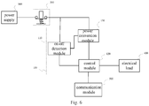
- FIG. 6 is a schematic diagram of an electronic device according to an exemplary embodiment.
- the electronic device includes the flash switch 200 and the flash switch on-off detection circuit 100 described above.
- the electronic device further includes an electrical load 400.
- the control module 120 in the flash switch on-off detection circuit 100 is also used for adjusting and controlling a working state of the electrical load 400 according to the on-off change of the flash switch 200.
- the electrical load is a light emitting device.
- the control module 120 adjusts and controls the working state of the electronic device to the lighting state or the switching-off state according to a one-time on-off state change of the flash switch 200.
- the control module 120 adjusts and controls the working state of the electronic device to a first brightness illumination state or a second brightness illumination state according to the one-time on-off state change of the flash switch 200.
- the electronic device may also be an intelligent hot water kettle, an intelligent sound box, an intelligent television, etc.
- the embodiment of the present disclosure is not specifically limited.
- the electronic device further includes a communication module 500.
- the communication module 500 is used to send the working state information of the electrical load to an external device, or receive a control instruction sent by the external device.
- the communication module 500 is connected with the control module 120 in the flash switch on-off detection circuit 100, such that information transmission between the communication module 500 and the control module 120 can be achieved.
- the external device is a host computer used together with the electronic device, such as a mobile phone, a personal computer, a gateway, etc.
- the electronic device can upload the current working state to the external device, such that the user can monitor the electronic device in real time, thereby improving use safety of the equipment and optimizing the user experience.
- the communication module 500 may be a wireless communication module, for example, a ZigBee communication module, a BLE communication module, a WiFi communication module, an infrared communication module, or an ISM band communication module.
- a wireless communication module for example, a ZigBee communication module, a BLE communication module, a WiFi communication module, an infrared communication module, or an ISM band communication module.
Landscapes
- Engineering & Computer Science (AREA)
- Power Engineering (AREA)
- Physics & Mathematics (AREA)
- General Physics & Mathematics (AREA)
- Business, Economics & Management (AREA)
- Emergency Management (AREA)
- Measurement Of Current Or Voltage (AREA)
- Electronic Switches (AREA)
Applications Claiming Priority (1)
| Application Number | Priority Date | Filing Date | Title |
|---|---|---|---|
| CN201911060939.6A CN110726931A (zh) | 2019-11-01 | 2019-11-01 | 闪断开关通断检测电路及电子设备 |
Publications (1)
| Publication Number | Publication Date |
|---|---|
| EP3817023A1 true EP3817023A1 (de) | 2021-05-05 |
Family
ID=69176994
Family Applications (1)
| Application Number | Title | Priority Date | Filing Date |
|---|---|---|---|
| EP20152296.8A Pending EP3817023A1 (de) | 2019-11-01 | 2020-01-16 | Schaltung und elektronische vorrichtung zur erkennung vom ein- und ausschalten eines blitzschalters |
Country Status (4)
| Country | Link |
|---|---|
| US (1) | US11874326B2 (de) |
| EP (1) | EP3817023A1 (de) |
| KR (1) | KR102420142B1 (de) |
| CN (1) | CN110726931A (de) |
Families Citing this family (6)
| Publication number | Priority date | Publication date | Assignee | Title |
|---|---|---|---|---|
| CN111537907A (zh) * | 2020-05-15 | 2020-08-14 | 北京小米移动软件有限公司 | 电源通断检测电路、方法、装置及存储介质 |
| JP7837592B2 (ja) * | 2021-10-01 | 2026-03-31 | イーエム コアーテック | 電磁波ノイズデータを提供するアクティブ補償装置 |
| CN114487674B (zh) * | 2022-01-25 | 2025-08-08 | 中车青岛四方机车车辆股份有限公司 | 线路状态测试方法及线路状态测试装置 |
| CN115453415B (zh) * | 2022-09-20 | 2025-08-19 | 青岛易来智能科技股份有限公司 | 闪断状态的检测电路、方法以及装置、电子设备 |
| CN115549305B (zh) * | 2022-10-27 | 2023-06-20 | 东方电子股份有限公司 | 一种压板状态检测系统 |
| CN116709613A (zh) * | 2023-05-24 | 2023-09-05 | 日炀(东莞)电子科技有限公司 | 工程建筑用器材设备及电子电路 |
Citations (5)
| Publication number | Priority date | Publication date | Assignee | Title |
|---|---|---|---|---|
| US9036320B1 (en) * | 2013-12-02 | 2015-05-19 | Elbex Video Ltd. | Mechanical latching relays and hybrid switches with latching relays for use in electrical automation |
| WO2019012104A1 (de) * | 2017-07-13 | 2019-01-17 | Moosburger Logistics Network And Development Kg | Steuer-schaltmodul für eine gebäudesteuerungseinrichtung und eine solche gebäudesteuerungseinrichtung |
| CN109951928A (zh) * | 2018-04-26 | 2019-06-28 | 青岛亿联客信息技术有限公司 | 一种闪断检测控制装置、包括其的电子设备及系统 |
| CN109963394A (zh) * | 2018-07-12 | 2019-07-02 | 青岛亿联客信息技术有限公司 | 一种闪断开关检测电路和智能灯具 |
| CN110286624A (zh) * | 2019-07-04 | 2019-09-27 | 北京小米移动软件有限公司 | 无线控制模组、无线墙壁开关、用电设备及系统 |
Family Cites Families (19)
| Publication number | Priority date | Publication date | Assignee | Title |
|---|---|---|---|---|
| CN85201577U (zh) * | 1985-05-19 | 1986-10-08 | 武汉大学 | 计算机控制不停电电源 |
| JPS62176325A (ja) * | 1986-01-30 | 1987-08-03 | Nec Ic Microcomput Syst Ltd | 電子スイツチ回路 |
| JPH063697B2 (ja) | 1988-02-29 | 1994-01-12 | 株式会社東芝 | スイッチオンオフ検出装置 |
| JP2001078446A (ja) * | 1999-06-29 | 2001-03-23 | Toshiba Corp | 電源装置 |
| JP4785804B2 (ja) * | 2006-08-04 | 2011-10-05 | 三菱電機株式会社 | 放電灯点灯装置及び照明器具及び照明システム及び出力表示器 |
| JP6003697B2 (ja) * | 2013-02-06 | 2016-10-05 | 株式会社デンソー | 噴射特性取得装置、及び噴射特性取得方法 |
| CN105101511A (zh) * | 2014-05-14 | 2015-11-25 | 宁波高新区赛尔富电子有限公司 | 一种感应开关装置及使用该感应开关装置的灯具 |
| CN204046602U (zh) * | 2014-07-25 | 2014-12-24 | 陕西千山航空电子有限责任公司 | 一种新型飞机地址位置报告装置 |
| KR101741945B1 (ko) | 2016-01-14 | 2017-05-31 | 호남대학교 산학협력단 | 다채널 전력량 통합관리 시스템 |
| CN205721163U (zh) * | 2016-04-28 | 2016-11-23 | 珠海格力电器股份有限公司 | 家用电器及其待机电路 |
| CN205753348U (zh) * | 2016-05-11 | 2016-11-30 | 徐州康博智能控制仪表有限公司 | 用电负荷限制装置 |
| JP6765225B2 (ja) | 2016-06-09 | 2020-10-07 | ローム株式会社 | スイッチ状態判定装置 |
| AT519064A1 (de) * | 2016-08-22 | 2018-03-15 | Ing Michael Meth Dipl | Lichtquellenschaltungseinrichtung |
| CN107135593B (zh) * | 2017-06-07 | 2023-12-05 | 深圳市奥金瑞科技有限公司 | 智能开关检测和识别电路 |
| CN207460027U (zh) * | 2017-11-08 | 2018-06-05 | 东莞市赛因电源有限公司 | 隔离型双向dc/ac电源 |
| CN108225166B (zh) * | 2017-12-18 | 2020-02-18 | 凯达威尔创新科技(深圳)有限公司 | 一种可实现无缝采样的模高指示器及其无缝采样方法 |
| CN109041374A (zh) * | 2018-07-12 | 2018-12-18 | 青岛亿联客信息技术有限公司 | 闪断开关检测电路及智能灯具 |
| WO2020211114A1 (zh) * | 2019-04-19 | 2020-10-22 | 青岛亿联客信息技术有限公司 | 一种闪断开关控制系统及其输入闪断检测电路 |
| CN211402638U (zh) * | 2019-11-01 | 2020-09-01 | 北京小米移动软件有限公司 | 闪断开关通断检测电路及电子设备 |
-
2019
- 2019-11-01 CN CN201911060939.6A patent/CN110726931A/zh active Pending
-
2020
- 2020-01-13 US US16/741,009 patent/US11874326B2/en active Active
- 2020-01-16 EP EP20152296.8A patent/EP3817023A1/de active Pending
- 2020-03-03 KR KR1020200026696A patent/KR102420142B1/ko active Active
Patent Citations (5)
| Publication number | Priority date | Publication date | Assignee | Title |
|---|---|---|---|---|
| US9036320B1 (en) * | 2013-12-02 | 2015-05-19 | Elbex Video Ltd. | Mechanical latching relays and hybrid switches with latching relays for use in electrical automation |
| WO2019012104A1 (de) * | 2017-07-13 | 2019-01-17 | Moosburger Logistics Network And Development Kg | Steuer-schaltmodul für eine gebäudesteuerungseinrichtung und eine solche gebäudesteuerungseinrichtung |
| CN109951928A (zh) * | 2018-04-26 | 2019-06-28 | 青岛亿联客信息技术有限公司 | 一种闪断检测控制装置、包括其的电子设备及系统 |
| CN109963394A (zh) * | 2018-07-12 | 2019-07-02 | 青岛亿联客信息技术有限公司 | 一种闪断开关检测电路和智能灯具 |
| CN110286624A (zh) * | 2019-07-04 | 2019-09-27 | 北京小米移动软件有限公司 | 无线控制模组、无线墙壁开关、用电设备及系统 |
Also Published As
| Publication number | Publication date |
|---|---|
| CN110726931A (zh) | 2020-01-24 |
| KR102420142B1 (ko) | 2022-07-12 |
| KR20210053131A (ko) | 2021-05-11 |
| US20210132149A1 (en) | 2021-05-06 |
| US11874326B2 (en) | 2024-01-16 |
Similar Documents
| Publication | Publication Date | Title |
|---|---|---|
| EP3817023A1 (de) | Schaltung und elektronische vorrichtung zur erkennung vom ein- und ausschalten eines blitzschalters | |
| US10020794B2 (en) | Wireless power transmitter apparatus having power transmitter apparatus and power reception apparatus supplied with electric power energy via space | |
| TWI643074B (zh) | 一種電源傳輸控制模組 | |
| EP2186180B1 (de) | Intelligente einrichtung und stromquelleninteraktion | |
| US10431940B1 (en) | Power receptacle with wireless control | |
| US11281175B2 (en) | Wireless control module, wireless wall switch, powered device and system | |
| KR101838741B1 (ko) | 도플러 센서를 사용한 대기전력 차단 콘센트 | |
| US20110012434A1 (en) | Power system with light-controlled function and the control method thereof | |
| US9577632B2 (en) | Wireless switching circuit | |
| TW201427312A (zh) | 電力線通訊裝置、電力線通訊系統及其監控電力的方法 | |
| CN210183218U (zh) | 开关控制电路及智能开关 | |
| CN111505370B (zh) | 过零检测电路、芯片、智能开关及过零检测方法 | |
| CN209844850U (zh) | 电源电路、芯片及智能开关 | |
| US8606214B2 (en) | Method of actuating a switch between a device and a power supply | |
| CA2651548A1 (en) | Alternating current power source | |
| CN111435147B (zh) | 可自动检测与调整零点相位的切换装置 | |
| US20160379782A1 (en) | Control system for a wireless power switch without a neutral wire | |
| AU2016275411A1 (en) | Power storage system, power storage device, and operation method for power storage device | |
| CN210572480U (zh) | 过零检测电路、芯片及智能开关 | |
| US9584023B2 (en) | Voltage converter | |
| CN111510002A (zh) | 电源电路、芯片、智能开关及电源供电方法 | |
| US20220148833A1 (en) | Controllable switch, dual-control switch and control system | |
| CN211402638U (zh) | 闪断开关通断检测电路及电子设备 | |
| CN211528958U (zh) | 一种物联网多控开关 | |
| EP3888422B1 (de) | Stromversorgung für eine led-beleuchtungseinheit |
Legal Events
| Date | Code | Title | Description |
|---|---|---|---|
| PUAI | Public reference made under article 153(3) epc to a published international application that has entered the european phase |
Free format text: ORIGINAL CODE: 0009012 |
|
| STAA | Information on the status of an ep patent application or granted ep patent |
Free format text: STATUS: REQUEST FOR EXAMINATION WAS MADE |
|
| 17P | Request for examination filed |
Effective date: 20201028 |
|
| AK | Designated contracting states |
Kind code of ref document: A1 Designated state(s): AL AT BE BG CH CY CZ DE DK EE ES FI FR GB GR HR HU IE IS IT LI LT LU LV MC MK MT NL NO PL PT RO RS SE SI SK SM TR |
|
| STAA | Information on the status of an ep patent application or granted ep patent |
Free format text: STATUS: EXAMINATION IS IN PROGRESS |
|
| 17Q | First examination report despatched |
Effective date: 20220705 |
|
| GRAP | Despatch of communication of intention to grant a patent |
Free format text: ORIGINAL CODE: EPIDOSNIGR1 |
|
| STAA | Information on the status of an ep patent application or granted ep patent |
Free format text: STATUS: GRANT OF PATENT IS INTENDED |
|
| INTG | Intention to grant announced |
Effective date: 20260107 |
|
| GRAS | Grant fee paid |
Free format text: ORIGINAL CODE: EPIDOSNIGR3 |
|
| GRAA | (expected) grant |
Free format text: ORIGINAL CODE: 0009210 |
|
| STAA | Information on the status of an ep patent application or granted ep patent |
Free format text: STATUS: THE PATENT HAS BEEN GRANTED |