EP3815946A1 - Achsantrieb mit einzeln angetriebenen radnaben - Google Patents
Achsantrieb mit einzeln angetriebenen radnaben Download PDFInfo
- Publication number
- EP3815946A1 EP3815946A1 EP20198012.5A EP20198012A EP3815946A1 EP 3815946 A1 EP3815946 A1 EP 3815946A1 EP 20198012 A EP20198012 A EP 20198012A EP 3815946 A1 EP3815946 A1 EP 3815946A1
- Authority
- EP
- European Patent Office
- Prior art keywords
- axle
- electric motors
- axle drive
- gear
- drive according
- Prior art date
- Legal status (The legal status is an assumption and is not a legal conclusion. Google has not performed a legal analysis and makes no representation as to the accuracy of the status listed.)
- Granted
Links
Images


Classifications
-
- B—PERFORMING OPERATIONS; TRANSPORTING
- B60—VEHICLES IN GENERAL
- B60K—ARRANGEMENT OR MOUNTING OF PROPULSION UNITS OR OF TRANSMISSIONS IN VEHICLES; ARRANGEMENT OR MOUNTING OF PLURAL DIVERSE PRIME-MOVERS IN VEHICLES; AUXILIARY DRIVES FOR VEHICLES; INSTRUMENTATION OR DASHBOARDS FOR VEHICLES; ARRANGEMENTS IN CONNECTION WITH COOLING, AIR INTAKE, GAS EXHAUST OR FUEL SUPPLY OF PROPULSION UNITS IN VEHICLES
- B60K7/00—Disposition of motor in, or adjacent to, traction wheel
- B60K7/0007—Disposition of motor in, or adjacent to, traction wheel the motor being electric
-
- B—PERFORMING OPERATIONS; TRANSPORTING
- B60—VEHICLES IN GENERAL
- B60K—ARRANGEMENT OR MOUNTING OF PROPULSION UNITS OR OF TRANSMISSIONS IN VEHICLES; ARRANGEMENT OR MOUNTING OF PLURAL DIVERSE PRIME-MOVERS IN VEHICLES; AUXILIARY DRIVES FOR VEHICLES; INSTRUMENTATION OR DASHBOARDS FOR VEHICLES; ARRANGEMENTS IN CONNECTION WITH COOLING, AIR INTAKE, GAS EXHAUST OR FUEL SUPPLY OF PROPULSION UNITS IN VEHICLES
- B60K17/00—Arrangement or mounting of transmissions in vehicles
- B60K17/04—Arrangement or mounting of transmissions in vehicles characterised by arrangement, location or kind of gearing
- B60K17/043—Transmission unit disposed in on near the vehicle wheel, or between the differential gear unit and the wheel
-
- B—PERFORMING OPERATIONS; TRANSPORTING
- B60—VEHICLES IN GENERAL
- B60K—ARRANGEMENT OR MOUNTING OF PROPULSION UNITS OR OF TRANSMISSIONS IN VEHICLES; ARRANGEMENT OR MOUNTING OF PLURAL DIVERSE PRIME-MOVERS IN VEHICLES; AUXILIARY DRIVES FOR VEHICLES; INSTRUMENTATION OR DASHBOARDS FOR VEHICLES; ARRANGEMENTS IN CONNECTION WITH COOLING, AIR INTAKE, GAS EXHAUST OR FUEL SUPPLY OF PROPULSION UNITS IN VEHICLES
- B60K7/00—Disposition of motor in, or adjacent to, traction wheel
- B60K2007/003—Disposition of motor in, or adjacent to, traction wheel with two or more motors driving a single wheel
-
- B—PERFORMING OPERATIONS; TRANSPORTING
- B60—VEHICLES IN GENERAL
- B60K—ARRANGEMENT OR MOUNTING OF PROPULSION UNITS OR OF TRANSMISSIONS IN VEHICLES; ARRANGEMENT OR MOUNTING OF PLURAL DIVERSE PRIME-MOVERS IN VEHICLES; AUXILIARY DRIVES FOR VEHICLES; INSTRUMENTATION OR DASHBOARDS FOR VEHICLES; ARRANGEMENTS IN CONNECTION WITH COOLING, AIR INTAKE, GAS EXHAUST OR FUEL SUPPLY OF PROPULSION UNITS IN VEHICLES
- B60K7/00—Disposition of motor in, or adjacent to, traction wheel
- B60K2007/0038—Disposition of motor in, or adjacent to, traction wheel the motor moving together with the wheel axle
-
- B—PERFORMING OPERATIONS; TRANSPORTING
- B60—VEHICLES IN GENERAL
- B60K—ARRANGEMENT OR MOUNTING OF PROPULSION UNITS OR OF TRANSMISSIONS IN VEHICLES; ARRANGEMENT OR MOUNTING OF PLURAL DIVERSE PRIME-MOVERS IN VEHICLES; AUXILIARY DRIVES FOR VEHICLES; INSTRUMENTATION OR DASHBOARDS FOR VEHICLES; ARRANGEMENTS IN CONNECTION WITH COOLING, AIR INTAKE, GAS EXHAUST OR FUEL SUPPLY OF PROPULSION UNITS IN VEHICLES
- B60K7/00—Disposition of motor in, or adjacent to, traction wheel
- B60K2007/0061—Disposition of motor in, or adjacent to, traction wheel the motor axle being parallel to the wheel axle
-
- B—PERFORMING OPERATIONS; TRANSPORTING
- B60—VEHICLES IN GENERAL
- B60Y—INDEXING SCHEME RELATING TO ASPECTS CROSS-CUTTING VEHICLE TECHNOLOGY
- B60Y2200/00—Type of vehicle
- B60Y2200/10—Road Vehicles
- B60Y2200/15—Fork lift trucks, Industrial trucks
-
- B—PERFORMING OPERATIONS; TRANSPORTING
- B60—VEHICLES IN GENERAL
- B60Y—INDEXING SCHEME RELATING TO ASPECTS CROSS-CUTTING VEHICLE TECHNOLOGY
- B60Y2200/00—Type of vehicle
- B60Y2200/60—Industrial applications, e.g. pipe inspection vehicles
- B60Y2200/62—Conveyors, floor conveyors
Definitions
- the invention relates to an axle drive of a mobile work machine, in particular an industrial truck, with electric motors for driving two individually driven wheel hubs arranged on an axle center line.
- a generic axle drive is described which is intended for use in an industrial truck designed as a forklift truck and comprises two individual wheel drives, each consisting of an electric motor, a transmission and a driven wheel hub.
- the electric motor of each individual wheel drive would be enlarged, which, however, in addition to the desired increase in performance, has some disadvantages.
- a larger diameter of the electric motors requires considerably more installation space, on the one hand for the electric motors themselves, on the other hand in the case of an axle drive, as disclosed in the cited publication, also as a result of their increased distance from the axle center line. This is at the expense of other components and can, for example, lead to a smaller installation space for a traction battery in a battery-powered vehicle. Furthermore, larger electric motors are often disproportionately expensive and, due to their dimensions and weight, can only be assembled with great effort.
- the present invention is based on the object of providing an axle drive of the type mentioned at the outset which, with increased performance, is optimized in particular with regard to relatively low construction and assembly costs and little space requirement.
- wheel hubs are each in drive connection with at least two electric motors mechanically coupled to one another to form a motor assembly.
- the idea that is essential to the invention is therefore to mechanically couple a plurality of electric motors, namely at least two electric motors, to form a motor assembly for each individual wheel drive of the axle drive, so that the electric motors of the motor assembly work together like a single large electric motor.
- Each motor network of a single wheel drive can be individually regulated with regard to drive torque and speed, in particular also as a function of a steering angle of the work machine equipped with the axle drive.
- Relatively small electric motors can be used, which, however, together provide the required power, as is required in a larger mobile work machine, in particular an industrial truck with a load capacity of over 8 tons.
- Such electric motors are often standard motors and are therefore available in relatively large numbers and inexpensively.
- the electric motors used in the axle drive according to the invention can easily be operated in the range of a favorable efficiency. This minimizes losses that would otherwise occur in the form of heat and which would increase the effort required to dissipate heat (e.g. larger cooling systems). Furthermore, this also reduces wear and tear and makes optimal use of the performance of the electric motors.
- the motor assemblies each have coaxially aligned electric motors with a common axis of rotation, i. H. the rotors of the electric motors in each motor group rotate around a common axis.
- the motor assemblies are each arranged axially parallel to the axle center line and axially parallel to one another and a connecting gear is arranged in the power flow between each motor assembly and the wheel hub driven by it.
- the connecting gears bridge the distance that exists due to the axially parallel arrangement of the motor assemblies to the axle center line, and serve to reduce the electric motor speed to the lower level of the wheel hub speed.
- the coaxially aligned electric motors of a motor assembly can each be arranged directly one behind the other, in which case the associated connecting gear is located at one of the two ends of such a series of electric motors.
- a first motor assembly has on its axis of rotation a first coupling shaft arranged axially between two electric motors, which is in drive connection at both shaft ends with one of the electric motors, and that a second motor assembly has an axially between having two electric motors arranged second coupling shaft, each with one of the two shaft ends Electric motors are in drive connection.
- the first coupling shaft is expediently provided with a first drive pinion, which forms an input element of a first connecting gear
- the second coupling shaft is provided with a second drive pinion, which forms an input element of a second connecting gear.
- the drive pinions are each advantageously designed as an input-side gear of the connecting gear, which is designed as a spur gear, each having an output-side gear which is arranged concentrically to the axis center line.
- Each gear wheel on the output side is in drive connection with a wheel hub, for example via an axle shaft which is provided with a spline which dips into a central bore machined into the output side gear which is provided with a complementary spline.
- the first and second connecting gears are preferably arranged parallel to one another.
- the first and the second connecting gear are spatially combined to form an axle gear, which results in advantages with regard to a small footprint and a construction requiring only relatively few components.
- axle drive is then located centrally between the electric motors.
- the axle drive can have a transmission housing that is common to the first and second connecting drives.
- the electric motors can be attached to the gear housing of the axle drive.
- Particularly favorable spatial conditions result when a first plane spanned by the axis center line and the axis of rotation of the first engine assembly and a second plane spanned by the axis center line and the rotation axis of the second engine assembly enclose an angle with one another.
- This angle is preferably less than 90 degrees, so it represents an acute angle.
- the axle drive illustrated according to the invention is part of an industrial truck designed as a counterbalanced forklift truck and is used as a non-steerable front axle 1.
- the axle drive is provided on both front sides of the front axle 1 with a wheel hub 2 or 3, on which a wheel can be attached (or two parallel adjacent wheels, corresponding to a tandem arrangement).
- the wheel hubs 2, 3 can be driven individually, ie they can be operated independently of one another with an individual drive torque and an individual speed.
- axle drive with individual wheel drives in contrast to an axle drive with a so-called differential drive axle, in which the drive force is distributed - normally evenly - to both wheel hubs via a differential gear.
- a plurality of retaining tabs H are provided on a cross member 4, with the aid of which a lifting frame can be tiltably attached to the forklift truck equipped with the front axle 1.
- each motor assembly M1, M2 can in principle also have more than two electric motors that are mechanically coupled to one another. Furthermore, designs are also possible in which the motor assemblies M1, M2 are not arranged axially parallel to the axis center line A and / or in which the electric motors are not coaxially aligned with one another.
- the axis center line A and the axis of rotation R1 of the first motor assembly M1 span a first plane F1.
- the axis center line A and the axis of rotation R1 and are located in a first plane F1.
- the axis center line A and the axis of rotation R2 of the second motor assembly M2 span a second plane F2.
- the two planes F1 and F2 enclose an acute angle W, that is to say an angle which is smaller than 90 degrees, in the present exemplary embodiment advantageously somewhat smaller than 60 degrees.
- the axis center line A and the axes of rotation R1, R2 of the motor assemblies M1, M2 form - seen in the axial direction - the corner points of an isosceles triangle, the base of which lies in a third plane F3 spanned by the rotational axes R1, R2 of the motor assemblies M1, M2.
- the apex of the triangle is therefore formed by the axis center line A.
- a first connecting gear V1 which is designed as a spur gear, has a first coupling shaft K1, which is provided with a drive pinion Z1 designed as a gear and is in drive connection at both shaft ends with one of the electric motors E1 or E2 of the first motor group M1 ( in the Figures 4a and 4b not shown). That in the Figure 4a When the final drive is fully assembled, the right end of the shaft of the first coupling shaft K1 is coupled to the electric motor E1 and the left end of the shaft is coupled to the electric motor E2 in a rotationally synchronous manner, for example via splines on the rotor shafts of the electric motors E1, E2, not shown. The splines mesh with complementary gears in the hollow coupling shaft K1.
- the drive pinion Z1 is in engagement with an intermediate gear Z11, which drives an output-side gear Z12 arranged concentrically to the axis center line A.
- a second connecting gear V2 which is also designed as a spur gear, has a second coupling shaft K2, which is provided with a drive pinion Z2 designed as a gear and is drive-connected at both shaft ends to one of the electric motors E3 or E4 of the second motor group M2. That in the Figure 4a The right end of the shaft of the second coupling shaft K2 is coupled to the electric motor E3 and the left end of the shaft is synchronously coupled to the electric motor E4, for example via splines on the rotor shafts of the electric motors E3, E4, which mesh with complementary teeth in the hollow coupling shaft K2.
- the drive pinion Z2 meshes with an intermediate gear Z21, which is a drives the output-side gearwheel Z22, which is arranged concentrically to the axis center line A.
- the drive pinions R1, R2 of the two connecting gears V1, V2 thus each form their input elements, while the gears Z12, Z22 each form the output elements of the connecting gears V1, V2.
- the output-side gears Z12 and Z22 drive the wheel hubs 2, 3 via axle shafts, not shown, which are each provided with a spline which engages in a central bore Z12a or Z22a of the gear Z12 or Z22, which is provided with a complementary spline.
- the two axle shafts and the two gear wheels Z12, Z22 coupled with them in a rotationally synchronous manner rotate independently of one another.
- An axial bearing L can be arranged axially between the two gears (roller or sliding bearing) in order to be able to absorb and transmit axial forces resulting from the helical gearing of the gears Z12, Z22 independently of speed differences.
- the two connecting gears V1, V2 are arranged parallel to one another and directly adjacent, so that - as in the present exemplary embodiment - they are spatially combined to form an axle gear AG in a space-saving manner.
- the close spatial proximity advantageously also makes it possible to use a common component for the two coupling shafts K1, K2, which is installed laterally reversed, i.e. rotated by 180 degrees, as the first or second coupling shaft K1 or K2, depending on the application.
- the intermediate gears Z11 and Z21 of the two connecting gears V1, V2 are structurally identical elements. This also applies to the two output-side gears Z22 and Z12.
- the electric motors E1, E2, E3, E4 are located on both sides of the axle drive AG, based on the axial extension of the axes of rotation R1, R2.
- surrounding housing G which is in the Figures 5a and 5b and is composed of two housing halves G1 and G2.
- Each housing half G1 or G2 is provided on the outside with fastening devices (eg ring flanges) for two electric motors.
- the housing G with the axle gear AG consisting of the two connecting gears V1 and V2 is arranged axially between the electric motors E1, E3 on one side and E2, E4 on the other side, with the electric motors E1 and E3 are attached to the housing half G1 and the electric motors E2 and E4 are attached to the housing half G2.
- FIGs 6 and 7th illustrate the installation of the axle gear AG consisting of the two connecting gears V1, V2 in the gear housing G.
- Figure 6 the empty housing half G2 from the inside and Figure 2 the housing half G2 after the installation of the gears of the axle drive AG.
Landscapes
- Engineering & Computer Science (AREA)
- Chemical & Material Sciences (AREA)
- Combustion & Propulsion (AREA)
- Transportation (AREA)
- Mechanical Engineering (AREA)
- Arrangement Or Mounting Of Propulsion Units For Vehicles (AREA)
Abstract
Description
- Die Erfindung betrifft einen Achsantrieb einer mobilen Arbeitsmaschine, insbesondere Flurförderzeug, mit Elektromotoren zum Antrieb von zwei auf einer Achsmittellinie angeordneten, einzeln angetriebenen Radnaben.
- In der
DE 1 430 322 ist ein gattungsgemäßer Achsantrieb beschrieben, der für den Einsatz in einem als Gabelstapler ausgebildeten Flurförderzeug vorgesehen ist und zwei Einzelradantriebe umfasst, die jeweils aus einem Elektromotor, einem Getriebe und einer angetriebenen Radnabe bestehen. - Gabelstapler, die über eine größere Hubkraft verfügen, als Gabelstapler des häufigsten Tragkraftbereichs bis 8 Tonnen Traglast, beispielsweise Fahrzeuge mit einer Traglast von 16 Tonnen und mehr, haben ein größeres Eigengewicht und müssen - mit oder ohne Last - durch einen Achsantrieb bewegt werden, der ausreichend leistungsfähig ist. Zu diesem Zweck würde man bei einem gattungsgemäßen Achsantrieb den Elektromotor jedes Einzelradantriebs vergrößern, was jedoch neben der erwünschten Leistungssteigerung einige Nachteile mit sich bringt.
- So wird durch einen größeren Durchmesser der Elektromotoren erheblich mehr Bauraum benötigt, einerseits für die Elektromotoren selbst, andererseits bei einem Achsantrieb, wie in der genannten Druckschrift offenbart, auch infolge deren vergrößerten Abstands zur Achsmittellinie. Dies geht zu Lasten anderer Komponenten und kann beispielsweise bei einem batterieelektrisch betriebenen Fahrzeug zu einem kleineren Bauraum für eine Traktionsbatterie führen. Ferner sind größere Elektromotoren häufig überproportional teuer und aufgrund ihrer Abmessungen und ihres Gewichts nur mit hohem Aufwand zu montieren. Schließlich kommt im Fahrbetrieb hinzu, dass infolge großer rotierender Massen der Rotoren der Elektromotoren und von rotierenden Elementen von Getrieben, die im Kraftfluss zwischen den Elektromotoren und den Radantrieben angeordnet sind, der Achsantrieb nur deutlich verzögert auf Beschleunigungs- und Bremsbefehle reagiert.
- Der vorliegenden Erfindung liegt die Aufgabe zu Grunde, einen Achsantrieb der eingangs genannten Art zur Verfügung zu stellen, der bei erhöhter Leistungsfähigkeit insbesondere im Hinblick auf einen relativ geringen Bau- und Montageaufwand und wenig Platzbedarf optimiert ist.
- Diese Aufgabe wird erfindungsgemäß dadurch gelöst, dass die Radnaben jeweils mit mindestens zwei, zu einem Motorenverbund mechanisch miteinander gekoppelten Elektromotoren in Antriebsverbindung stehen.
- Vorteilhafte Ausgestaltungen und Weiterbildungen der Erfindung sind Gegenstand von Unteransprüchen.
- Der erfindungswesentliche Gedanke besteht demnach darin, für jeden Einzelradantrieb des Achsantriebs anstelle von jeweils einem vergrößerten Elektromotor eine Mehrzahl von Elektromotoren, nämlich mindestens zwei Elektromotoren, zu einem Motorenverbund mechanisch miteinander zu koppeln, so dass die Elektromotoren des Motorenverbunds zusammen wie ein einzelner großer Elektromotor wirken. Jeder Motorenverbund eines Einzelradantriebs kann dabei einzeln bezüglich Antriebsmoment und Drehzahl geregelt werden, insbesondere auch in Abhängigkeit eines Lenkwinkels der mit dem Achsantrieb ausgestatteten Arbeitsmaschine.
- Dabei können relativ kleine Elektromotoren verwendet werden, die jedoch in ihrer Summe die gewünschte Leistung zur Verfügung stellen, wie sie in einer größeren mobilen Arbeitsmaschine, insbesondere einem Flurförderzeug mit einem Tragkraftbereich über 8 Tonnen Traglast, erforderlich ist. Solche Elektromotoren sind häufig Standardmotoren und daher in relativ hohen Stückzahlen und preiswert verfügbar. Darüber hinaus sind sie aufgrund ihres relativ geringen Bauvolumens und Gewichts einfach zu montieren und zu warten.
- Die im erfindungsgemäßen Achsantrieb zum Einsatz kommenden Elektromotoren lassen sich leicht im Bereich eines günstigen Wirkungsgrads betreiben. Dadurch werden Verluste mimimiert, die andernfalls in Form von Wärme anfallen und den Aufwand zum Abführen von Wärme erhöhen würden (z.B. größere Kühlanlage). Ferner wird dadurch auch der Verschleiß verringert und die Leistungsfähigkeit der Elektromotoren optimal genutzt.
- Durch relativ kleine Durchmesser der Rotoren der Elektromotoren und der sich drehenden Elemente in nachgeschalteten Getrieben bleiben die rotierenden Massen klein.
- Bei Ausfall eines Elektromotors in einem Motorenverbund fällt dieser nicht vollständig aus, sondern der oder die verbleibenden Elektromotoren des vom Ausfall betroffenen Motorenverbunds vermögen nach wie vor Leistung in den Achsantrieb einzuspeisen. Es kommt daher nicht zu unvorhergesehenen Lenkreaktionen des Fahrzeugs, wie sie bei einem Komplettausfall eines der Einzelradantriebe dadurch entstehen könnten, dass das Antriebsmoment des Achsantriebs in einem solchen Zustand nur noch von einer der Radnaben übertragen wird.
- Gemäß einer Weiterbildung der Erfindung weisen die Motorenverbunde jeweils koaxial zueinander fluchtende Elektromotoren mit gemeinsamer Rotationsachse auf, d. h. die Rotoren der Elektromotoren jedes Motorenverbunds drehen sich um eine gemeinsame Achse.
- In Ausgestaltung der Erfindung wird vorgeschlagen, dass die Motorenverbunde jeweils achsparallel zur Achsmittellinie und achsparallel zueinander angeordnet sind und im Kraftfluss zwischen jedem Motorenverbund und der davon angetriebenen Radnabe ein Verbindungsgetriebe angeordnet ist. Die Verbindungsgetriebe überbrücken den Abstand, der durch die achsparallele Anordnung der Motorenverbunde zur Achsmittellinie vorhanden ist, und dienen der Herabsetzung der Elektromotordrehzahl auf das niedrigere Niveau der Radnabendrehzahl.
- Die koaxial zueinander fluchtenden Elektromotoren eines Motorenverbunds können jeweils unmittelbar hintereinander angeordnet sein, wobei sich in diesem Fall das zugeordnete Verbindungsgetriebe an einem der beiden Enden einer solchen Aneinanderreihung von Elektromotoren befindet.
- Gemäß einer Weiterbildung der Erfindung wird jedoch bevorzugt, dass ein erster Motorenverbund auf seiner Rotationsachse eine axial zwischen zwei Elektromotoren angeordnete erste Koppelwelle aufweist, die an beiden Wellenenden jeweils mit einem der Elektromotore in Antriebsverbindung steht, und dass ein zweiter Motorenverbund auf seiner Rotationsachse eine axial zwischen zwei Elektromotoren angeordnete zweite Koppelwelle aufweist, die an beiden Wellenenden jeweils mit einem der Elektromotore in Antriebsverbindung steht. Dadurch kann axial zwischen den Elektromotoren Leistung abgegriffen werden und es lässt sich eine platzsparende Bauweise erzielen.
- Zweckmäßigerweise ist die erste Koppelwelle mit einem ersten Antriebsritzel versehen, welches ein Eingangselement eines ersten Verbindungsgetriebes bildet, und ist die zweite Koppelwelle mit einem zweiten Antriebsritzel versehen, welches ein Eingangselement eines zweiten Verbindungsgetriebes bildet.
- Die Antriebsritzel sind mit Vorteil jeweils als eingangsseitiges Zahnrad der als Stirnradgetriebe ausgeführten Verbindungsgetriebe ausgebildet, die jeweils ein ausgangsseitiges Zahnrad aufweisen, das konzentrisch zur Achsmittelinie angeordnet ist. Jedes ausgangsseitige Zahnrad steht mit einer Radnabe in Antriebsverbindung, beispielsweise über eine Achswelle, die mit einer Keilverzahnung versehen ist, welche in eine in das ausgangsseitige Zahnrad eingearbeitete zentrische Bohrung eintaucht, die mit einer komplementären Keilverzahnung versehen ist.
- Das erste und das zweite Verbindungsgetriebe sind bevorzugt parallel zueinander angeordnet.
- Hierbei sind in Weiterbildung der Erfindung das erste und das zweite Verbindungsgetriebe zu einem Achsgetriebe räumlich zusammengefasst, wodurch sich Vorteile im Hinblick auf einen geringen Platzbedarf und eine nur relativ wenige Bauteile erfordernde Bauweise ergeben.
- Sofern die Elektromotoren - bezogen auf die Axialerstreckung der Rotationsachsen - beiderseits des Achsgetriebes angeordnet sind, ergeben sich symmetrische Verhältnisse. Das Achsgetriebe befindet sich dann zentral zwischen den Elektromotoren.
- Dabei kann das Achsgetriebe ein für das erste und das zweite Verbindungstriebe gemeinsames Getriebegehäuse aufweisen.
- Die Elektromotoren können am Getriebegehäuse des Achsgetriebes befestigt sein.
- Besonders günstige Platzverhältnisse ergeben sich, wenn eine von der Achsmittelinie und der Rotationsachse des ersten Motorenverbunds aufgespannte erste Ebene und eine von der Achsmittellinie und der Rotationsachse des zweiten Motorenverbunds aufgespannte zweite Ebene einen Winkel miteinander einschließen.
- Dieser Winkel ist bevorzugt kleiner als 90 Grad, stellt also einen spitzen Winkel dar.
- Es erweist sich als günstig, wenn die Achsmittellinie und die Rotationsachsen der Motorenverbunde - in Axialrichtung gesehen - die Eckpunkte eines gleichschenkligen Dreiecks bilden, dessen Basis in einer von den Rotationsachsen der Motorenverbunde aufgespannten dritten Ebene liegt.
- Weitere Vorteile und Einzelheiten der Erfindung werden anhand des in den schematischen Figuren dargestellten Ausführungsbeispiels näher erläutert. Dabei zeigt
- Figur 1
- eine perspektivische Ansicht eines erfindungsgemäßen Achsantriebs,
- Figur 2
- eine weitere perspektische Ansicht des Achsantriebs,
- Figur 3
- eine Ansicht des Achsantriebs in Blickrichtung zu einer der Stirnseiten,
- Figur 4a
- eine perspektivische Ansicht von Verbindungsgetrieben des Achsantriebs,
- Figur 4b
- eine weitere perspektivische Ansicht der Verbindungsgetriebe,
- Figur 5a
- eine perspektivische Ansicht eines Getriebegehäuses des Achsgetriebes des Achsantriebs,
- Figur 5b
- eine weitere perspektivische Ansicht des Getriebegehäuses des Achsgetriebes des Achsantriebs,
- Figur 6
- eine perspektivische Ansicht einer Getriebegehäusehälfte des Achsgetriebes von innen und
- Figur 7
- eine perspektivische Ansicht der in
Fig. 6 dargestellten Getriebegehäusehälfte mit eingebautem Achsgetriebe. - Der in
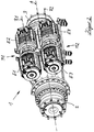
Fig. 1 dargestellte erfindungsmäße Achsantrieb ist im vorliegenden Ausführungsbeispiel Teil eines als Gegengewichts-Gabelstapler ausgebildeten Flurförderzeugs und wird als nicht lenkbare Vorderachse 1 verwendet. Der Achsantrieb ist an beiden Stirnseiten der Vorderachse 1 jeweils mit einer Radnabe 2 bzw. 3 versehen, auf der ein Rad befestigbar ist (oder zwei parallel benachbarte Räder, entsprechend einer Tandemanordnung). Die Radnaben 2, 3 sind einzeln antreibbar, d.h. sie können unabhängig voneinander mit einem individuelen Antriebsmoment und einer individuellen Drehzahl betrieben werden. - Mithin handelt es sich hier um einen Achsantrieb mit Einzelradantrieben - im Gegensatz zu einem Achsantrieb mit einer sogenannten Differential-Antriebsachse, bei der über ein Differentialgetriebe Antriebskraft - normalerweise gleichmäßig - auf beide Radnaben verteilt wird.
- An der in Fahrtrichtung vorderen Seite sind an einem Querträger 4 mehrere Haltelaschen H vorgesehen, mit deren Hilfe ein Hubgerüst an dem mit der Vorderachse 1 ausgestatteten Gabelstapler neigbar befestigbar ist.
- Achsparallel zu einer Achsmittellinie A sind für den Antrieb der Radnaben 2, 3 mehrere Elektromotoren angeordnet, von denen in der
Figur 1 zwei koaxial zueinander fluchtende Elektromotoren E1 und E2 erkennbar sind, die auf noch zu beschreibende Weise mechanisch miteinander zu einem ersten Motorenverbund M1 gekoppelt sind, der eine gemeinsame Rotationsachse R1 der Elektromotoren E1 und E2 aufweist und zum Antrieb der in derFigur 1 rechten Radnabe 2 vorgesehen ist. - Dies geschieht mit Hilfe eines Verbindungsgetriebes, mit dem die Antriebsleistung des ersten Motorenverbunds M1 in die Radnabe 2 eingespeist wird. Zugleich erfolgt eine Herabsetzung der Drehzahl des ersten Motorenverbunds M1 auf das niedrigere Drehzahlniveau der Radnabe 2 und es wird der Abstand zwischen der Rotationsachse R1 des ersten Motorenverbunds M1 und der Achsmittellinie A überbrückt.
- Von dem im Zusammenhang mit der Beschreibung der
Figuren 4a und4b noch im Detail zu erläuternden Verbindungsgetriebe ist inFigur 1 lediglich ein unteres Ende eines Getriebegehäuses G erkennbar, in dem sich das dem ersten Motorenverbund M1 zugeordnete Verbindungsgetriebe als Teil eines Achsgetriebes befindet. Das untere Ende des Getriebegehäuses G ist durch eine mittige Ausnehmung 4a im Querträger 4 sichtbar. Der erste Motorenverbund M1 bildet zusammen mit der Radnabe 2 und dem zwischengeschalteten Verbindungsgetriebe einen ersten Einzelradantrieb. - Aus der Darstellung gemäß
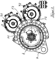
Figur 2 ist erkennbar, dass unterhalb des ersten Motorenverbunds M1 ein zu dessen Rotationsachse R1 und zur Achsmittellinie A achsparalleler zweiter Motorenverbund M2 angeordnet ist, der - in analoger Bauweise zum ersten Motorenverbund M1 - zwei koaxial zueinander fluchtende und mechanisch miteinander gekoppelte Elektromotoren E3, E4 aufweist, so dass sich eine gemeinsame Rotationsachse R2 der Elektromotoren E3 und E4 des zweiten Motorenverbunds M2 ergibt. Dieser zweite Motorenverbund M2 ist über ein zweites Verbindungsgetriebe mit der in derFigur 2 rechten Radnabe 3 verbunden, wobei sich ein zweiter Einzelradantrieb ergibt. - Es versteht sich, dass jeder Motorenverbund M1, M2 grundsätzlich auch mehr als zwei Elektromotoren aufweisen kann, die mechanisch miteinander gekoppelt sind. Ferner sind auch Bauweisen möglich, bei denen die Motorverbunde M1, M2 nicht achsparallel zur Achsmittellinie A angeordnet sind und/oder bei denen die Elektromotoren nicht koaxial zueinander fluchten.
- Wie sich in der Zusammenschau mit
Figur 3 des vorliegenden Ausführungsbeispiels ergibt, spannen die Achsmittellinie A und die Rotationsachse R1 des ersten Motorenverbunds M1 eine erste Ebene F1 auf. Anders ausgedrückt, die Achsmittellinie A und die Rotationsachse R1 bzw. befinden sich in einer ersten Ebene F1. Die Achsmittellinie A und die Rotationsachse R2 des zweiten Motorenverbunds M2 spannen eine zweite Ebene F2 auf. Die beiden Ebenen F1 und F2 schließen einen spitzen Winkel W ein, also einen Winkel, der kleiner als 90 Grad ist, im vorliegenden Ausführungsbeispiel vorteilhafterweise etwas kleiner als 60 Grad. - Die Achsmittellinie A und die Rotationsachsen R1, R2 der Motorenverbunde M1, M2 bilden - in Axialrichtung gesehen - die Eckpunkte eines gleichschenkligen Dreiecks, dessen Basis in einer von den Rotationsachsen R1, R2 der Motorenverbunde M1, M2 aufgespannten dritte Ebene F3 liegt. Die Dreiecksspitze wird demnach von der Achsmittellinie A gebildet.
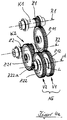
- In den
Figuren 4a und4b sind die Verbindungsgetriebe dargestellt, mit deren Hilfe der in Einzelradantriebsbauweise ausgeführte Achsantrieb Leistung von den Elektromotoren E1, E2, E3, E4 der beiden Motorenverbunde M1, M2 zu den Radnaben 2, 3 überträgt und die Drehzahl herabsetzt. Zugleich wird durch die Verbindungsgetriebe V1, V2 auch der Abstand zwischen den Rotationsachsen R1, R2 und der Achsmittellinie A überbrückt. - Hierbei weist ein erstes Verbindungsgetriebe V1, das als Stirnradgetriebe ausgeführt ist, eine erste Koppelwelle K1 auf, das mit einem als Zahnrad ausgebildeten Antriebsritzel Z1 versehen ist und an beiden Wellenenden jeweils mit einem der Elektromotore E1 bzw. E2 des ersten Motorenverbunds M1 in Antriebsverbindung steht (in den
Figuren 4a und4b nicht dargestellt). Das in derFigur 4a rechte Wellenende der ersten Koppelwelle K1 ist bei vollständig montiertem Achsantrieb mit dem Elektromotor E1 und das linke Wellenende mit dem Elektromotor E2 drehsynchron gekoppelt, beispielsweise über Keilverzahnungen auf den nicht dargestellten Rotorwellen der Elektromotoren E1, E2. Die Keilverzahnungen greifen in dazu komplementäre Verzahnungen in der hohlen Koppelwelle K1 ein. Das Antriebsritzel Z1 steht in Eingriff mit einem Zwischenzahnrad Z11, das ein ausgangsseitiges, konzentrisch zur Achsmittellinie A angeordnetes Zahnrad Z12 antreibt. - Ein zweites Verbindungsgetriebe V2, das ebenfalls als Stirnradgetriebe ausgeführt ist, weist eine zweite Koppelwelle K2 auf, die mit einem als Zahnrad ausgebildeten Antriebsritzel Z2 versehen ist und an beiden Wellenenden jeweils mit einem der Elektromotore E3 bzw. E4 des zweiten Motorenverbunds M2 antriebsverbunden ist. Das in der
Figur 4a rechte Wellenende der zweiten Koppelwelle K2 ist mit dem Elektromotor E3 und das linke Wellenende mit dem Elektromotor E4 drehsynchron gekoppelt, beispielsweise über Keilverzahnungen auf den Rotorwellen der Elektromotoren E3, E4, die in dazu komplementäre Verzahnungen in der hohlen Koppelwelle K2 eingreifen. Das Antriebsritzel Z2 steht in Eingriff mit einem Zwischenzahnrad Z21, das ein ausgangsseitiges, konzentrisch zur Achsmittellinie A angeordnetes Zahnrad Z22 antreibt. - Die Antriebsritzel R1, R2 der beiden Verbindungsgetriebe V1, V2 bilden somit jeweils deren Eingangselemente, während die Zahnräder Z12, Z22 jeweils die Ausgangselemente der Verbindungsgetriebe V1, V2 bilden.
- Die ausgangsseitigen Zahnräder Z12 und Z22 treiben die Radnaben 2, 3 über nicht dargestellte Achswellen an, die jeweils mit einer Keilverzahnung versehen sind, welche in eine zentrische, mit einer komplementären Keilverzahnung versehenen Bohrung Z12a bzw. Z22a des Zahnrads Z12 bzw. Z22 eingreift. Die beiden Achswellen und die beiden damit drehsynchron gekoppelten Zahnräder Z12, Z22 rotieren unabhängig voneinander. Axial zwischen den beiden Zahnrädern kann ein Axiallager L angeordnet sein (Wälz- oder Gleitlager), um aus einer Schrägverzahnung der Zahnräder Z12, Z22 resultierende Axialkräfte unabhängig von Drehzahldifferenzen zwängungsfrei aufnehmen und übertragen zu können.
- Es versteht sich, dass im Bereich der Radnaben 2, 3 jeweils ein zusätzliches Getriebe zur weiteren Drehzahlherabsetzung vorgesehen sein kann (Radnabengetriebe).
- Die beiden Verbindungsgetriebe V1, V2 sind parallel zueinander angeordnet und unmittelbar benachbart, so dass sie - wie im vorliegenden Ausführungsbeispiel - platzsparend zu einem Achsgetriebe AG räumlich zusammengefasst sind. Die enge räumliche Nachbarschaft ermöglicht es vorteilhafterweise auch, für die beiden Koppelwellen K1, K2 ein gemeinsames Bauteil zu benutzen, das je nach Einsatz als erste oder zweite Koppelwelle K1 bzw. K2 seitenverkehrt, also um 180 Grad verdreht, eingebaut wird.
- Bei den Zwischenzahnrädern Z11 und Z21 der beiden Verbindungsgetriebe V1, V2 handelt es sich um baugleiche Elemente. Die gilt gleichfalls für die beiden ausgangsseitigen Zahnräder Z22 und Z12.
- Bei der vorliegenden Konstruktion befinden sich die Elektromotoren E1, E2, E3, E4-bezogen auf die Axialerstreckung der Rotationsachsen R1, R2 - beiderseits des Achsgetriebes AG. Dieses verfügt über ein bereits im Zusammenhang mit der Beschreibung zu
Figur 1 erwähntes, umgebendes Gehäuse G, das in denFiguren 5a und5b dargestellt und aus zwei Gehäusehälften G1 und G2 zusammengesetzt ist. Jede Gehäusehälfte G1 bzw. G2 ist außen mit Befestigungseinrichtungen (z.B. Ringflansche) für jeweils zwei Elektromotoren versehen. Somit ist im montierten Zustand des Achsantriebs das Gehäuse G mit dem darin angeordneten, aus den zwei Verbindungsgetrieben V1 und V2 bestehenden Achsgetriebe AG axial zwischen den Elektromotoren E1, E3 auf der einen Seite und E2, E4 auf der anderen Seite angeordnet, wobei die Elektromotoren E1 und E3 an der Gehäusehälfte G1 und die Elektromotoren E2 und E4 an der Gehäusehälfte G2 befestigt sind. - Die
Figuren 6 und7 veranschaulichen den Einbau des aus den beiden Verbindungsgetrieben V1, V2 bestehenden Achsgetriebes AG in das Getriebegehäuse G. Hierbei zeigtFigur 6 die leere Gehäusehälfte G2 von innen undFigur 2 die Gehäusehälfte G2 nach dem Einbau der Zahnräder des Achsgetriebes AG.
Claims (14)
- Achsantrieb einer mobilen Arbeitsmaschine, insbesondere Flurförderzeug, mit Elektromotoren (E1, E2, E3, E4) zum Antrieb von zwei auf einer Achsmittellinie (A) angeordneten, einzeln angetriebenen Radnaben (2, 3), dadurch gekennzeichnet, dass die Radnaben (2, 3) jeweils mit mindestens zwei, zu einem Motorenverbund (M1 bzw. M2) mechanisch miteinander gekoppelte Elektromotoren (E1, E2 bzw. E3, E4) in Antriebsverbindung stehen.
- Achsantrieb nach Anspruch 1, dadurch gekennzeichnet, dass die Motorenverbunde (M1, M2) jeweils koaxial zueinander fluchtende Elektromotoren (E1, E2 bzw. E3, E4) mit gemeinsamer Rotationsachse (R1 bzw. R2) aufweisen.
- Achsantrieb nach Anspruch 2, dadurch gekennzeichnet, dass die Motorenverbunde (M1, M2) jeweils achsparallel zur Achsmittellinie (A) und achsparallel zueinander angeordnet sind und im Kraftfluss zwischen jedem Motorenverbund (M1 bzw. M2) und der davon angetriebenen Radnabe (2 bzw. 3) ein Verbindungsgetriebe (V1 bzw. V2) angeordnet ist.
- Achsantrieb nach Anspruch 2 oder 3, dadurch gekennzeichnet, dass ein erster Motorenverbund (M1) auf seiner Rotationsachse (R1) eine axial zwischen zwei Elektromotoren (E1, E2) angeordnete erste Koppelwelle (K1) aufweist, die an beiden Wellenenden jeweils mit einem der Elektromotore (E1 bzw. E2) in Antriebsverbindung stehen, und dass ein zweiter Motorenverbund (M2) auf seiner Rotationsachse (R2) eine axial zwischen zwei Elektromotoren (E3, E4) angeordnete zweite Koppelwelle (K2) aufweist, die an beiden Wellenenden jeweils mit einem der Elektromotore (E3 bzw. E4) in Antriebsverbindung stehen.
- Achsantrieb nach Anspruch 4, dadurch gekennzeichnet, dass die erste Koppelwelle (K1) mit einem ersten Antriebsritzel (Z1) versehen ist, welches ein Eingangselement eines ersten Verbindungsgetriebes (V1) bildet, und dass die zweite Koppelwelle (K2) mit einem zweiten Antriebsritzel (Z2) versehen ist, welches ein Eingangselement eines zweiten Verbindungsgetriebes (V2) bildet.
- Achsantrieb nach Anspruch 5, dadurch gekennzeichnet, dass die Antriebsritzel (Z1, Z2) jeweils als eingangsseitiges Zahnrad der als Stirnradgetriebe ausgeführten Verbindungsgetriebe (V1, V2) ausgebildet sind, die jeweils ein ausgangsseitiges Zahnrad (Z12 bzw. Z22) aufweisen, das konzentrisch zur Achsmittelinie (A) angeordnet ist.
- Achsantrieb nach einem der Ansprüche 3 bis 6, dadurch gekennzeichnet, dass das erste (V1) und das zweite Verbindungsgetriebe (V2) parallel zueinander angeordnet sind.
- Achsantrieb nach einem der Ansprüche 3 bis 7, dadurch gekennzeichnet, dass das erste (V1) und das zweite Verbindungsgetriebe (V2) zu einem Achsgetriebe (AG) räumlich zusammengefasst sind.
- Achsantrieb nach Anspruch 8, dadurch gekennzeichnet, dass die Elektromotoren (E1, E2, E3, E4) - bezogen auf die Axialerstreckung der Rotationsachsen (R1, R2) - beiderseits des Achsgetriebes (AG) angeordnet sind.
- Achsantrieb nach Anspruch 8 oder 9, dadurch gekennzeichnet, dass das Achsgetriebe (AG) ein für das erste (V1) und das zweite Verbindungsgetriebe (V2) gemeinsames Getriebegehäuse (G) aufweist.
- Achsantrieb nach Anspruch 10, dadurch gekennzeichnet, dass die Elektromotoren (E1, E2, E3, E4) am Getriebegehäuse (G) des Achsgetriebes (AG) befestigt sind.
- Achsantrieb nach einem der Ansprüche 3 bis 11, dadurch gekennzeichnet, dass eine von der Achsmittelinie (A) und der Rotationsachse (R1) des ersten Motorenverbunds (M1) aufgespannte erste Ebene (F1) und eine von der Achsmittellinie (A) und der Rotationsachse (R2) des zweiten Motorenverbunds (M2) aufgespannte zweite Ebene (F2) einen Winkel (W) miteinander einschließen.
- Achsantrieb nach Anspruch 12, dadurch gekennzeichnet, dass der Winkel (W) kleiner als 90 Grad ist.
- Achsantrieb nach Anspruch 12 oder 13, dadurch gekennzeichnet, dass die Achsmittellinie (A) und die Rotationsachsen (R1, R2) der Motorenverbunde (M1, M2) - in Axialrichtung gesehen - die Eckpunkte eines gleichschenkligen Dreiecks bilden, dessen Basis in einer von den Rotationsachsen (R1, R2) der Motorenverbunde (M1, M2) aufgespannten dritten Ebene (F3) liegt.
Applications Claiming Priority (1)
| Application Number | Priority Date | Filing Date | Title |
|---|---|---|---|
| DE102019129025.2A DE102019129025A1 (de) | 2019-10-28 | 2019-10-28 | Achsantrieb mit einzeln angetriebenen Radnaben |
Publications (2)
| Publication Number | Publication Date |
|---|---|
| EP3815946A1 true EP3815946A1 (de) | 2021-05-05 |
| EP3815946B1 EP3815946B1 (de) | 2023-05-24 |
Family
ID=72644135
Family Applications (1)
| Application Number | Title | Priority Date | Filing Date |
|---|---|---|---|
| EP20198012.5A Active EP3815946B1 (de) | 2019-10-28 | 2020-09-24 | Achsantrieb mit einzeln angetriebenen radnaben |
Country Status (2)
| Country | Link |
|---|---|
| EP (1) | EP3815946B1 (de) |
| DE (1) | DE102019129025A1 (de) |
Cited By (1)
| Publication number | Priority date | Publication date | Assignee | Title |
|---|---|---|---|---|
| CN117325637A (zh) * | 2023-11-28 | 2024-01-02 | 江苏速豹动力科技有限公司 | 电驱桥和电动卡车 |
Citations (4)
| Publication number | Priority date | Publication date | Assignee | Title |
|---|---|---|---|---|
| DE1430322A1 (de) | 1962-09-19 | 1968-11-14 | Hans Still Gmbh | UEbersetzungsgetriebe fuer mit gleichachsigen Elektromotoren auszuruestende Fahrzeuge,insbesondere Flurfoerdergeraete |
| EP2921331A1 (de) * | 2014-03-20 | 2015-09-23 | Askoll Holding S.r.l. a socio unico | Integrierte Antriebsstranganordnung für ein Elektrofahrzeug, insbesondere für einen Kleinwagen und Elektrofahrzeug, das diese Antriebsanordnung umfasst |
| CN105922858A (zh) * | 2016-05-13 | 2016-09-07 | 杨勇 | 一种组合型电动车驱动装置 |
| WO2019064733A1 (ja) * | 2017-09-29 | 2019-04-04 | 日立建機株式会社 | 電気駆動作業車両および車輪電気駆動ユニット |
-
2019
- 2019-10-28 DE DE102019129025.2A patent/DE102019129025A1/de not_active Withdrawn
-
2020
- 2020-09-24 EP EP20198012.5A patent/EP3815946B1/de active Active
Patent Citations (4)
| Publication number | Priority date | Publication date | Assignee | Title |
|---|---|---|---|---|
| DE1430322A1 (de) | 1962-09-19 | 1968-11-14 | Hans Still Gmbh | UEbersetzungsgetriebe fuer mit gleichachsigen Elektromotoren auszuruestende Fahrzeuge,insbesondere Flurfoerdergeraete |
| EP2921331A1 (de) * | 2014-03-20 | 2015-09-23 | Askoll Holding S.r.l. a socio unico | Integrierte Antriebsstranganordnung für ein Elektrofahrzeug, insbesondere für einen Kleinwagen und Elektrofahrzeug, das diese Antriebsanordnung umfasst |
| CN105922858A (zh) * | 2016-05-13 | 2016-09-07 | 杨勇 | 一种组合型电动车驱动装置 |
| WO2019064733A1 (ja) * | 2017-09-29 | 2019-04-04 | 日立建機株式会社 | 電気駆動作業車両および車輪電気駆動ユニット |
Cited By (2)
| Publication number | Priority date | Publication date | Assignee | Title |
|---|---|---|---|---|
| CN117325637A (zh) * | 2023-11-28 | 2024-01-02 | 江苏速豹动力科技有限公司 | 电驱桥和电动卡车 |
| CN117325637B (zh) * | 2023-11-28 | 2024-02-06 | 江苏速豹动力科技有限公司 | 电驱桥和电动卡车 |
Also Published As
| Publication number | Publication date |
|---|---|
| DE102019129025A1 (de) | 2021-04-29 |
| EP3815946B1 (de) | 2023-05-24 |
Similar Documents
| Publication | Publication Date | Title |
|---|---|---|
| DE102007040475B4 (de) | Stirnraddifferential für ein Kraftfahrzeug mit scheibenförmigen, angeschweißten Trägern | |
| EP3027455B1 (de) | Antriebsstrang eines kraftfahrzeugs | |
| EP2212588B1 (de) | Differentialgetriebe mit leichten trägerteilen und visco-kupplung | |
| EP3580080B1 (de) | Aufbau eines getriebes für ein hybridfahrzeug, antriebsstrang und hybridfahrzeug | |
| WO2013174740A1 (de) | Reibrollenplanetengetriebe sowie übersetzungs- und ausgleichsgetriebe | |
| DE102015214035A1 (de) | Elektronische Antriebseinheit für ein Kraftfahrzeug | |
| DE102011087579A1 (de) | Stirnraddifferenzial mit auf Trägerteil zentriertem Antriebsrad | |
| EP2776299B1 (de) | Getriebeeinheit | |
| DE102019124666B4 (de) | Differenzialgetriebe | |
| EP3768994B1 (de) | Planetengetriebe mit einzahnigem sonnenrad mit evoloidverzahnung | |
| EP2657059B1 (de) | Antriebsvorrichtung für Tandemachsen | |
| DE102015224892B4 (de) | Ölversorgung eines schmal bauenden Differenzialgetriebes | |
| EP3815946B1 (de) | Achsantrieb mit einzeln angetriebenen radnaben | |
| DE102016210078A1 (de) | Kompaktes Planetengetriebe | |
| WO2017016552A1 (de) | Getriebeanordnung für ein kraftfahrzeug | |
| DE102015220522B4 (de) | Schmal bauendes Differenzialgetriebe mit großen Seitenrädern | |
| DE102018207749A1 (de) | Schaltbares Radnabengetriebe | |
| DE102017219548A1 (de) | Zahnradanordnung | |
| DE19636052A1 (de) | Differential mit Vorbelastungssteuerung | |
| DE102009027342A1 (de) | Überlagerungsgetriebe für ein Lenksystem | |
| DE102008015400B4 (de) | Differentialanordnung zur gesteuerten Verteilung eines Antriebsmomentes | |
| DE102023200463A1 (de) | Antriebsstrang für eine Antriebsachse eines Fahrzeugs, Antriebsachse sowie Fahrzeug mit einer solchen Antriebsachse | |
| DE102018128837A1 (de) | Getriebevorrichtung für ein Kraftfahrzeug | |
| WO2013013950A2 (de) | Getriebemotor | |
| DE102009040817A1 (de) | Antriebseinheit für ein Kraftfahrzeug |
Legal Events
| Date | Code | Title | Description |
|---|---|---|---|
| PUAI | Public reference made under article 153(3) epc to a published international application that has entered the european phase |
Free format text: ORIGINAL CODE: 0009012 |
|
| STAA | Information on the status of an ep patent application or granted ep patent |
Free format text: STATUS: THE APPLICATION HAS BEEN PUBLISHED |
|
| AK | Designated contracting states |
Kind code of ref document: A1 Designated state(s): AL AT BE BG CH CY CZ DE DK EE ES FI FR GB GR HR HU IE IS IT LI LT LU LV MC MK MT NL NO PL PT RO RS SE SI SK SM TR |
|
| STAA | Information on the status of an ep patent application or granted ep patent |
Free format text: STATUS: REQUEST FOR EXAMINATION WAS MADE |
|
| 17P | Request for examination filed |
Effective date: 20211026 |
|
| RBV | Designated contracting states (corrected) |
Designated state(s): AL AT BE BG CH CY CZ DE DK EE ES FI FR GB GR HR HU IE IS IT LI LT LU LV MC MK MT NL NO PL PT RO RS SE SI SK SM TR |
|
| GRAP | Despatch of communication of intention to grant a patent |
Free format text: ORIGINAL CODE: EPIDOSNIGR1 |
|
| STAA | Information on the status of an ep patent application or granted ep patent |
Free format text: STATUS: GRANT OF PATENT IS INTENDED |
|
| RIC1 | Information provided on ipc code assigned before grant |
Ipc: B60K 17/04 20060101ALI20221122BHEP Ipc: B60K 7/00 20060101AFI20221122BHEP |
|
| INTG | Intention to grant announced |
Effective date: 20221208 |
|
| GRAS | Grant fee paid |
Free format text: ORIGINAL CODE: EPIDOSNIGR3 |
|
| GRAA | (expected) grant |
Free format text: ORIGINAL CODE: 0009210 |
|
| STAA | Information on the status of an ep patent application or granted ep patent |
Free format text: STATUS: THE PATENT HAS BEEN GRANTED |
|
| AK | Designated contracting states |
Kind code of ref document: B1 Designated state(s): AL AT BE BG CH CY CZ DE DK EE ES FI FR GB GR HR HU IE IS IT LI LT LU LV MC MK MT NL NO PL PT RO RS SE SI SK SM TR |
|
| REG | Reference to a national code |
Ref country code: GB Ref legal event code: FG4D Free format text: NOT ENGLISH |
|
| REG | Reference to a national code |
Ref country code: CH Ref legal event code: EP |
|
| REG | Reference to a national code |
Ref country code: DE Ref legal event code: R096 Ref document number: 502020003320 Country of ref document: DE |
|
| P01 | Opt-out of the competence of the unified patent court (upc) registered |
Effective date: 20230507 |
|
| REG | Reference to a national code |
Ref country code: AT Ref legal event code: REF Ref document number: 1569308 Country of ref document: AT Kind code of ref document: T Effective date: 20230615 |
|
| REG | Reference to a national code |
Ref country code: IE Ref legal event code: FG4D Free format text: LANGUAGE OF EP DOCUMENT: GERMAN |
|
| REG | Reference to a national code |
Ref country code: LT Ref legal event code: MG9D |
|
| REG | Reference to a national code |
Ref country code: NL Ref legal event code: MP Effective date: 20230524 |
|
| PG25 | Lapsed in a contracting state [announced via postgrant information from national office to epo] |
Ref country code: SE Free format text: LAPSE BECAUSE OF FAILURE TO SUBMIT A TRANSLATION OF THE DESCRIPTION OR TO PAY THE FEE WITHIN THE PRESCRIBED TIME-LIMIT Effective date: 20230524 Ref country code: PT Free format text: LAPSE BECAUSE OF FAILURE TO SUBMIT A TRANSLATION OF THE DESCRIPTION OR TO PAY THE FEE WITHIN THE PRESCRIBED TIME-LIMIT Effective date: 20230925 Ref country code: NO Free format text: LAPSE BECAUSE OF FAILURE TO SUBMIT A TRANSLATION OF THE DESCRIPTION OR TO PAY THE FEE WITHIN THE PRESCRIBED TIME-LIMIT Effective date: 20230824 Ref country code: NL Free format text: LAPSE BECAUSE OF FAILURE TO SUBMIT A TRANSLATION OF THE DESCRIPTION OR TO PAY THE FEE WITHIN THE PRESCRIBED TIME-LIMIT Effective date: 20230524 Ref country code: ES Free format text: LAPSE BECAUSE OF FAILURE TO SUBMIT A TRANSLATION OF THE DESCRIPTION OR TO PAY THE FEE WITHIN THE PRESCRIBED TIME-LIMIT Effective date: 20230524 |
|
| PG25 | Lapsed in a contracting state [announced via postgrant information from national office to epo] |
Ref country code: RS Free format text: LAPSE BECAUSE OF FAILURE TO SUBMIT A TRANSLATION OF THE DESCRIPTION OR TO PAY THE FEE WITHIN THE PRESCRIBED TIME-LIMIT Effective date: 20230524 Ref country code: PL Free format text: LAPSE BECAUSE OF FAILURE TO SUBMIT A TRANSLATION OF THE DESCRIPTION OR TO PAY THE FEE WITHIN THE PRESCRIBED TIME-LIMIT Effective date: 20230524 Ref country code: LV Free format text: LAPSE BECAUSE OF FAILURE TO SUBMIT A TRANSLATION OF THE DESCRIPTION OR TO PAY THE FEE WITHIN THE PRESCRIBED TIME-LIMIT Effective date: 20230524 Ref country code: LT Free format text: LAPSE BECAUSE OF FAILURE TO SUBMIT A TRANSLATION OF THE DESCRIPTION OR TO PAY THE FEE WITHIN THE PRESCRIBED TIME-LIMIT Effective date: 20230524 Ref country code: IS Free format text: LAPSE BECAUSE OF FAILURE TO SUBMIT A TRANSLATION OF THE DESCRIPTION OR TO PAY THE FEE WITHIN THE PRESCRIBED TIME-LIMIT Effective date: 20230924 Ref country code: HR Free format text: LAPSE BECAUSE OF FAILURE TO SUBMIT A TRANSLATION OF THE DESCRIPTION OR TO PAY THE FEE WITHIN THE PRESCRIBED TIME-LIMIT Effective date: 20230524 Ref country code: GR Free format text: LAPSE BECAUSE OF FAILURE TO SUBMIT A TRANSLATION OF THE DESCRIPTION OR TO PAY THE FEE WITHIN THE PRESCRIBED TIME-LIMIT Effective date: 20230825 |
|
| PG25 | Lapsed in a contracting state [announced via postgrant information from national office to epo] |
Ref country code: FI Free format text: LAPSE BECAUSE OF FAILURE TO SUBMIT A TRANSLATION OF THE DESCRIPTION OR TO PAY THE FEE WITHIN THE PRESCRIBED TIME-LIMIT Effective date: 20230524 |
|
| PG25 | Lapsed in a contracting state [announced via postgrant information from national office to epo] |
Ref country code: SK Free format text: LAPSE BECAUSE OF FAILURE TO SUBMIT A TRANSLATION OF THE DESCRIPTION OR TO PAY THE FEE WITHIN THE PRESCRIBED TIME-LIMIT Effective date: 20230524 |
|
| PG25 | Lapsed in a contracting state [announced via postgrant information from national office to epo] |
Ref country code: SM Free format text: LAPSE BECAUSE OF FAILURE TO SUBMIT A TRANSLATION OF THE DESCRIPTION OR TO PAY THE FEE WITHIN THE PRESCRIBED TIME-LIMIT Effective date: 20230524 Ref country code: SK Free format text: LAPSE BECAUSE OF FAILURE TO SUBMIT A TRANSLATION OF THE DESCRIPTION OR TO PAY THE FEE WITHIN THE PRESCRIBED TIME-LIMIT Effective date: 20230524 Ref country code: RO Free format text: LAPSE BECAUSE OF FAILURE TO SUBMIT A TRANSLATION OF THE DESCRIPTION OR TO PAY THE FEE WITHIN THE PRESCRIBED TIME-LIMIT Effective date: 20230524 Ref country code: EE Free format text: LAPSE BECAUSE OF FAILURE TO SUBMIT A TRANSLATION OF THE DESCRIPTION OR TO PAY THE FEE WITHIN THE PRESCRIBED TIME-LIMIT Effective date: 20230524 Ref country code: DK Free format text: LAPSE BECAUSE OF FAILURE TO SUBMIT A TRANSLATION OF THE DESCRIPTION OR TO PAY THE FEE WITHIN THE PRESCRIBED TIME-LIMIT Effective date: 20230524 Ref country code: CZ Free format text: LAPSE BECAUSE OF FAILURE TO SUBMIT A TRANSLATION OF THE DESCRIPTION OR TO PAY THE FEE WITHIN THE PRESCRIBED TIME-LIMIT Effective date: 20230524 |
|
| REG | Reference to a national code |
Ref country code: DE Ref legal event code: R097 Ref document number: 502020003320 Country of ref document: DE |
|
| PLBE | No opposition filed within time limit |
Free format text: ORIGINAL CODE: 0009261 |
|
| STAA | Information on the status of an ep patent application or granted ep patent |
Free format text: STATUS: NO OPPOSITION FILED WITHIN TIME LIMIT |
|
| REG | Reference to a national code |
Ref country code: CH Ref legal event code: PL |
|
| 26N | No opposition filed |
Effective date: 20240227 |
|
| PG25 | Lapsed in a contracting state [announced via postgrant information from national office to epo] |
Ref country code: SI Free format text: LAPSE BECAUSE OF FAILURE TO SUBMIT A TRANSLATION OF THE DESCRIPTION OR TO PAY THE FEE WITHIN THE PRESCRIBED TIME-LIMIT Effective date: 20230524 |
|
| PG25 | Lapsed in a contracting state [announced via postgrant information from national office to epo] |
Ref country code: LU Free format text: LAPSE BECAUSE OF NON-PAYMENT OF DUE FEES Effective date: 20230924 |
|
| REG | Reference to a national code |
Ref country code: BE Ref legal event code: MM Effective date: 20230930 |
|
| PG25 | Lapsed in a contracting state [announced via postgrant information from national office to epo] |
Ref country code: SI Free format text: LAPSE BECAUSE OF FAILURE TO SUBMIT A TRANSLATION OF THE DESCRIPTION OR TO PAY THE FEE WITHIN THE PRESCRIBED TIME-LIMIT Effective date: 20230524 Ref country code: LU Free format text: LAPSE BECAUSE OF NON-PAYMENT OF DUE FEES Effective date: 20230924 Ref country code: IT Free format text: LAPSE BECAUSE OF FAILURE TO SUBMIT A TRANSLATION OF THE DESCRIPTION OR TO PAY THE FEE WITHIN THE PRESCRIBED TIME-LIMIT Effective date: 20230524 Ref country code: MC Free format text: LAPSE BECAUSE OF FAILURE TO SUBMIT A TRANSLATION OF THE DESCRIPTION OR TO PAY THE FEE WITHIN THE PRESCRIBED TIME-LIMIT Effective date: 20230524 |
|
| REG | Reference to a national code |
Ref country code: IE Ref legal event code: MM4A |
|
| PG25 | Lapsed in a contracting state [announced via postgrant information from national office to epo] |
Ref country code: IE Free format text: LAPSE BECAUSE OF NON-PAYMENT OF DUE FEES Effective date: 20230924 |
|
| PG25 | Lapsed in a contracting state [announced via postgrant information from national office to epo] |
Ref country code: CH Free format text: LAPSE BECAUSE OF NON-PAYMENT OF DUE FEES Effective date: 20230930 |
|
| PG25 | Lapsed in a contracting state [announced via postgrant information from national office to epo] |
Ref country code: IE Free format text: LAPSE BECAUSE OF NON-PAYMENT OF DUE FEES Effective date: 20230924 Ref country code: CH Free format text: LAPSE BECAUSE OF NON-PAYMENT OF DUE FEES Effective date: 20230930 |
|
| PG25 | Lapsed in a contracting state [announced via postgrant information from national office to epo] |
Ref country code: BE Free format text: LAPSE BECAUSE OF NON-PAYMENT OF DUE FEES Effective date: 20230930 |
|
| PG25 | Lapsed in a contracting state [announced via postgrant information from national office to epo] |
Ref country code: BG Free format text: LAPSE BECAUSE OF FAILURE TO SUBMIT A TRANSLATION OF THE DESCRIPTION OR TO PAY THE FEE WITHIN THE PRESCRIBED TIME-LIMIT Effective date: 20230524 |
|
| PG25 | Lapsed in a contracting state [announced via postgrant information from national office to epo] |
Ref country code: BG Free format text: LAPSE BECAUSE OF FAILURE TO SUBMIT A TRANSLATION OF THE DESCRIPTION OR TO PAY THE FEE WITHIN THE PRESCRIBED TIME-LIMIT Effective date: 20230524 |
|
| GBPC | Gb: european patent ceased through non-payment of renewal fee |
Effective date: 20240924 |
|
| PG25 | Lapsed in a contracting state [announced via postgrant information from national office to epo] |
Ref country code: GB Free format text: LAPSE BECAUSE OF NON-PAYMENT OF DUE FEES Effective date: 20240924 |
|
| PG25 | Lapsed in a contracting state [announced via postgrant information from national office to epo] |
Ref country code: CY Free format text: LAPSE BECAUSE OF FAILURE TO SUBMIT A TRANSLATION OF THE DESCRIPTION OR TO PAY THE FEE WITHIN THE PRESCRIBED TIME-LIMIT; INVALID AB INITIO Effective date: 20200924 |
|
| PG25 | Lapsed in a contracting state [announced via postgrant information from national office to epo] |
Ref country code: HU Free format text: LAPSE BECAUSE OF FAILURE TO SUBMIT A TRANSLATION OF THE DESCRIPTION OR TO PAY THE FEE WITHIN THE PRESCRIBED TIME-LIMIT; INVALID AB INITIO Effective date: 20200924 |
|
| PGFP | Annual fee paid to national office [announced via postgrant information from national office to epo] |
Ref country code: DE Payment date: 20250919 Year of fee payment: 6 |
|
| PGFP | Annual fee paid to national office [announced via postgrant information from national office to epo] |
Ref country code: AT Payment date: 20251020 Year of fee payment: 5 Ref country code: FR Payment date: 20250922 Year of fee payment: 6 |
|
| PG25 | Lapsed in a contracting state [announced via postgrant information from national office to epo] |
Ref country code: TR Free format text: LAPSE BECAUSE OF FAILURE TO SUBMIT A TRANSLATION OF THE DESCRIPTION OR TO PAY THE FEE WITHIN THE PRESCRIBED TIME-LIMIT Effective date: 20230524 |