EP3815755A1 - Golf club and manufacturing method thereof - Google Patents
Golf club and manufacturing method thereof Download PDFInfo
- Publication number
- EP3815755A1 EP3815755A1 EP19835019.1A EP19835019A EP3815755A1 EP 3815755 A1 EP3815755 A1 EP 3815755A1 EP 19835019 A EP19835019 A EP 19835019A EP 3815755 A1 EP3815755 A1 EP 3815755A1
- Authority
- EP
- European Patent Office
- Prior art keywords
- coating layer
- amorphous alloy
- golf club
- based amorphous
- base part
- Prior art date
- Legal status (The legal status is an assumption and is not a legal conclusion. Google has not performed a legal analysis and makes no representation as to the accuracy of the status listed.)
- Pending
Links
Images




Classifications
-
- C—CHEMISTRY; METALLURGY
- C22—METALLURGY; FERROUS OR NON-FERROUS ALLOYS; TREATMENT OF ALLOYS OR NON-FERROUS METALS
- C22C—ALLOYS
- C22C33/00—Making ferrous alloys
- C22C33/02—Making ferrous alloys by powder metallurgy
- C22C33/0257—Making ferrous alloys by powder metallurgy characterised by the range of the alloying elements
- C22C33/0278—Making ferrous alloys by powder metallurgy characterised by the range of the alloying elements with at least one alloying element having a minimum content above 5%
- C22C33/0285—Making ferrous alloys by powder metallurgy characterised by the range of the alloying elements with at least one alloying element having a minimum content above 5% with Cr, Co, or Ni having a minimum content higher than 5%
-
- A—HUMAN NECESSITIES
- A63—SPORTS; GAMES; AMUSEMENTS
- A63B—APPARATUS FOR PHYSICAL TRAINING, GYMNASTICS, SWIMMING, CLIMBING, OR FENCING; BALL GAMES; TRAINING EQUIPMENT
- A63B53/00—Golf clubs
- A63B53/04—Heads
- A63B53/047—Heads iron-type
-
- B—PERFORMING OPERATIONS; TRANSPORTING
- B05—SPRAYING OR ATOMISING IN GENERAL; APPLYING FLUENT MATERIALS TO SURFACES, IN GENERAL
- B05D—PROCESSES FOR APPLYING FLUENT MATERIALS TO SURFACES, IN GENERAL
- B05D7/00—Processes, other than flocking, specially adapted for applying liquids or other fluent materials to particular surfaces or for applying particular liquids or other fluent materials
- B05D7/14—Processes, other than flocking, specially adapted for applying liquids or other fluent materials to particular surfaces or for applying particular liquids or other fluent materials to metal, e.g. car bodies
-
- B—PERFORMING OPERATIONS; TRANSPORTING
- B22—CASTING; POWDER METALLURGY
- B22F—WORKING METALLIC POWDER; MANUFACTURE OF ARTICLES FROM METALLIC POWDER; MAKING METALLIC POWDER; APPARATUS OR DEVICES SPECIALLY ADAPTED FOR METALLIC POWDER
- B22F3/00—Manufacture of workpieces or articles from metallic powder characterised by the manner of compacting or sintering; Apparatus specially adapted therefor ; Presses and furnaces
- B22F3/10—Sintering only
-
- B—PERFORMING OPERATIONS; TRANSPORTING
- B22—CASTING; POWDER METALLURGY
- B22F—WORKING METALLIC POWDER; MANUFACTURE OF ARTICLES FROM METALLIC POWDER; MAKING METALLIC POWDER; APPARATUS OR DEVICES SPECIALLY ADAPTED FOR METALLIC POWDER
- B22F9/00—Making metallic powder or suspensions thereof
- B22F9/02—Making metallic powder or suspensions thereof using physical processes
- B22F9/06—Making metallic powder or suspensions thereof using physical processes starting from liquid material
- B22F9/08—Making metallic powder or suspensions thereof using physical processes starting from liquid material by casting, e.g. through sieves or in water, by atomising or spraying
- B22F9/082—Making metallic powder or suspensions thereof using physical processes starting from liquid material by casting, e.g. through sieves or in water, by atomising or spraying atomising using a fluid
-
- B—PERFORMING OPERATIONS; TRANSPORTING
- B33—ADDITIVE MANUFACTURING TECHNOLOGY
- B33Y—ADDITIVE MANUFACTURING, i.e. MANUFACTURING OF THREE-DIMENSIONAL [3D] OBJECTS BY ADDITIVE DEPOSITION, ADDITIVE AGGLOMERATION OR ADDITIVE LAYERING, e.g. BY 3D PRINTING, STEREOLITHOGRAPHY OR SELECTIVE LASER SINTERING
- B33Y10/00—Processes of additive manufacturing
-
- B—PERFORMING OPERATIONS; TRANSPORTING
- B33—ADDITIVE MANUFACTURING TECHNOLOGY
- B33Y—ADDITIVE MANUFACTURING, i.e. MANUFACTURING OF THREE-DIMENSIONAL [3D] OBJECTS BY ADDITIVE DEPOSITION, ADDITIVE AGGLOMERATION OR ADDITIVE LAYERING, e.g. BY 3D PRINTING, STEREOLITHOGRAPHY OR SELECTIVE LASER SINTERING
- B33Y70/00—Materials specially adapted for additive manufacturing
-
- B—PERFORMING OPERATIONS; TRANSPORTING
- B33—ADDITIVE MANUFACTURING TECHNOLOGY
- B33Y—ADDITIVE MANUFACTURING, i.e. MANUFACTURING OF THREE-DIMENSIONAL [3D] OBJECTS BY ADDITIVE DEPOSITION, ADDITIVE AGGLOMERATION OR ADDITIVE LAYERING, e.g. BY 3D PRINTING, STEREOLITHOGRAPHY OR SELECTIVE LASER SINTERING
- B33Y70/00—Materials specially adapted for additive manufacturing
- B33Y70/10—Composites of different types of material, e.g. mixtures of ceramics and polymers or mixtures of metals and biomaterials
-
- B—PERFORMING OPERATIONS; TRANSPORTING
- B33—ADDITIVE MANUFACTURING TECHNOLOGY
- B33Y—ADDITIVE MANUFACTURING, i.e. MANUFACTURING OF THREE-DIMENSIONAL [3D] OBJECTS BY ADDITIVE DEPOSITION, ADDITIVE AGGLOMERATION OR ADDITIVE LAYERING, e.g. BY 3D PRINTING, STEREOLITHOGRAPHY OR SELECTIVE LASER SINTERING
- B33Y80/00—Products made by additive manufacturing
-
- C—CHEMISTRY; METALLURGY
- C22—METALLURGY; FERROUS OR NON-FERROUS ALLOYS; TREATMENT OF ALLOYS OR NON-FERROUS METALS
- C22C—ALLOYS
- C22C33/00—Making ferrous alloys
- C22C33/003—Making ferrous alloys making amorphous alloys
-
- C—CHEMISTRY; METALLURGY
- C22—METALLURGY; FERROUS OR NON-FERROUS ALLOYS; TREATMENT OF ALLOYS OR NON-FERROUS METALS
- C22C—ALLOYS
- C22C33/00—Making ferrous alloys
- C22C33/02—Making ferrous alloys by powder metallurgy
- C22C33/0257—Making ferrous alloys by powder metallurgy characterised by the range of the alloying elements
- C22C33/0278—Making ferrous alloys by powder metallurgy characterised by the range of the alloying elements with at least one alloying element having a minimum content above 5%
- C22C33/0292—Making ferrous alloys by powder metallurgy characterised by the range of the alloying elements with at least one alloying element having a minimum content above 5% with more than 5% preformed carbides, nitrides or borides
-
- C—CHEMISTRY; METALLURGY
- C22—METALLURGY; FERROUS OR NON-FERROUS ALLOYS; TREATMENT OF ALLOYS OR NON-FERROUS METALS
- C22C—ALLOYS
- C22C38/00—Ferrous alloys, e.g. steel alloys
- C22C38/18—Ferrous alloys, e.g. steel alloys containing chromium
- C22C38/22—Ferrous alloys, e.g. steel alloys containing chromium with molybdenum or tungsten
-
- C—CHEMISTRY; METALLURGY
- C22—METALLURGY; FERROUS OR NON-FERROUS ALLOYS; TREATMENT OF ALLOYS OR NON-FERROUS METALS
- C22C—ALLOYS
- C22C38/00—Ferrous alloys, e.g. steel alloys
- C22C38/18—Ferrous alloys, e.g. steel alloys containing chromium
- C22C38/32—Ferrous alloys, e.g. steel alloys containing chromium with boron
-
- C—CHEMISTRY; METALLURGY
- C22—METALLURGY; FERROUS OR NON-FERROUS ALLOYS; TREATMENT OF ALLOYS OR NON-FERROUS METALS
- C22C—ALLOYS
- C22C45/00—Amorphous alloys
- C22C45/02—Amorphous alloys with iron as the major constituent
-
- C—CHEMISTRY; METALLURGY
- C22—METALLURGY; FERROUS OR NON-FERROUS ALLOYS; TREATMENT OF ALLOYS OR NON-FERROUS METALS
- C22C—ALLOYS
- C22C45/00—Amorphous alloys
- C22C45/10—Amorphous alloys with molybdenum, tungsten, niobium, tantalum, titanium, or zirconium or Hf as the major constituent
-
- C—CHEMISTRY; METALLURGY
- C23—COATING METALLIC MATERIAL; COATING MATERIAL WITH METALLIC MATERIAL; CHEMICAL SURFACE TREATMENT; DIFFUSION TREATMENT OF METALLIC MATERIAL; COATING BY VACUUM EVAPORATION, BY SPUTTERING, BY ION IMPLANTATION OR BY CHEMICAL VAPOUR DEPOSITION, IN GENERAL; INHIBITING CORROSION OF METALLIC MATERIAL OR INCRUSTATION IN GENERAL
- C23C—COATING METALLIC MATERIAL; COATING MATERIAL WITH METALLIC MATERIAL; SURFACE TREATMENT OF METALLIC MATERIAL BY DIFFUSION INTO THE SURFACE, BY CHEMICAL CONVERSION OR SUBSTITUTION; COATING BY VACUUM EVAPORATION, BY SPUTTERING, BY ION IMPLANTATION OR BY CHEMICAL VAPOUR DEPOSITION, IN GENERAL
- C23C4/00—Coating by spraying the coating material in the molten state, e.g. by flame, plasma or electric discharge
- C23C4/04—Coating by spraying the coating material in the molten state, e.g. by flame, plasma or electric discharge characterised by the coating material
- C23C4/06—Metallic material
-
- C—CHEMISTRY; METALLURGY
- C23—COATING METALLIC MATERIAL; COATING MATERIAL WITH METALLIC MATERIAL; CHEMICAL SURFACE TREATMENT; DIFFUSION TREATMENT OF METALLIC MATERIAL; COATING BY VACUUM EVAPORATION, BY SPUTTERING, BY ION IMPLANTATION OR BY CHEMICAL VAPOUR DEPOSITION, IN GENERAL; INHIBITING CORROSION OF METALLIC MATERIAL OR INCRUSTATION IN GENERAL
- C23C—COATING METALLIC MATERIAL; COATING MATERIAL WITH METALLIC MATERIAL; SURFACE TREATMENT OF METALLIC MATERIAL BY DIFFUSION INTO THE SURFACE, BY CHEMICAL CONVERSION OR SUBSTITUTION; COATING BY VACUUM EVAPORATION, BY SPUTTERING, BY ION IMPLANTATION OR BY CHEMICAL VAPOUR DEPOSITION, IN GENERAL
- C23C4/00—Coating by spraying the coating material in the molten state, e.g. by flame, plasma or electric discharge
- C23C4/04—Coating by spraying the coating material in the molten state, e.g. by flame, plasma or electric discharge characterised by the coating material
- C23C4/06—Metallic material
- C23C4/067—Metallic material containing free particles of non-metal elements, e.g. carbon, silicon, boron, phosphorus or arsenic
-
- C—CHEMISTRY; METALLURGY
- C23—COATING METALLIC MATERIAL; COATING MATERIAL WITH METALLIC MATERIAL; CHEMICAL SURFACE TREATMENT; DIFFUSION TREATMENT OF METALLIC MATERIAL; COATING BY VACUUM EVAPORATION, BY SPUTTERING, BY ION IMPLANTATION OR BY CHEMICAL VAPOUR DEPOSITION, IN GENERAL; INHIBITING CORROSION OF METALLIC MATERIAL OR INCRUSTATION IN GENERAL
- C23C—COATING METALLIC MATERIAL; COATING MATERIAL WITH METALLIC MATERIAL; SURFACE TREATMENT OF METALLIC MATERIAL BY DIFFUSION INTO THE SURFACE, BY CHEMICAL CONVERSION OR SUBSTITUTION; COATING BY VACUUM EVAPORATION, BY SPUTTERING, BY ION IMPLANTATION OR BY CHEMICAL VAPOUR DEPOSITION, IN GENERAL
- C23C4/00—Coating by spraying the coating material in the molten state, e.g. by flame, plasma or electric discharge
- C23C4/04—Coating by spraying the coating material in the molten state, e.g. by flame, plasma or electric discharge characterised by the coating material
- C23C4/06—Metallic material
- C23C4/08—Metallic material containing only metal elements
-
- C—CHEMISTRY; METALLURGY
- C23—COATING METALLIC MATERIAL; COATING MATERIAL WITH METALLIC MATERIAL; CHEMICAL SURFACE TREATMENT; DIFFUSION TREATMENT OF METALLIC MATERIAL; COATING BY VACUUM EVAPORATION, BY SPUTTERING, BY ION IMPLANTATION OR BY CHEMICAL VAPOUR DEPOSITION, IN GENERAL; INHIBITING CORROSION OF METALLIC MATERIAL OR INCRUSTATION IN GENERAL
- C23C—COATING METALLIC MATERIAL; COATING MATERIAL WITH METALLIC MATERIAL; SURFACE TREATMENT OF METALLIC MATERIAL BY DIFFUSION INTO THE SURFACE, BY CHEMICAL CONVERSION OR SUBSTITUTION; COATING BY VACUUM EVAPORATION, BY SPUTTERING, BY ION IMPLANTATION OR BY CHEMICAL VAPOUR DEPOSITION, IN GENERAL
- C23C4/00—Coating by spraying the coating material in the molten state, e.g. by flame, plasma or electric discharge
- C23C4/12—Coating by spraying the coating material in the molten state, e.g. by flame, plasma or electric discharge characterised by the method of spraying
- C23C4/129—Flame spraying
-
- C—CHEMISTRY; METALLURGY
- C23—COATING METALLIC MATERIAL; COATING MATERIAL WITH METALLIC MATERIAL; CHEMICAL SURFACE TREATMENT; DIFFUSION TREATMENT OF METALLIC MATERIAL; COATING BY VACUUM EVAPORATION, BY SPUTTERING, BY ION IMPLANTATION OR BY CHEMICAL VAPOUR DEPOSITION, IN GENERAL; INHIBITING CORROSION OF METALLIC MATERIAL OR INCRUSTATION IN GENERAL
- C23C—COATING METALLIC MATERIAL; COATING MATERIAL WITH METALLIC MATERIAL; SURFACE TREATMENT OF METALLIC MATERIAL BY DIFFUSION INTO THE SURFACE, BY CHEMICAL CONVERSION OR SUBSTITUTION; COATING BY VACUUM EVAPORATION, BY SPUTTERING, BY ION IMPLANTATION OR BY CHEMICAL VAPOUR DEPOSITION, IN GENERAL
- C23C4/00—Coating by spraying the coating material in the molten state, e.g. by flame, plasma or electric discharge
- C23C4/12—Coating by spraying the coating material in the molten state, e.g. by flame, plasma or electric discharge characterised by the method of spraying
- C23C4/134—Plasma spraying
-
- B—PERFORMING OPERATIONS; TRANSPORTING
- B05—SPRAYING OR ATOMISING IN GENERAL; APPLYING FLUENT MATERIALS TO SURFACES, IN GENERAL
- B05D—PROCESSES FOR APPLYING FLUENT MATERIALS TO SURFACES, IN GENERAL
- B05D2202/00—Metallic substrate
- B05D2202/10—Metallic substrate based on Fe
- B05D2202/15—Stainless steel
-
- B—PERFORMING OPERATIONS; TRANSPORTING
- B05—SPRAYING OR ATOMISING IN GENERAL; APPLYING FLUENT MATERIALS TO SURFACES, IN GENERAL
- B05D—PROCESSES FOR APPLYING FLUENT MATERIALS TO SURFACES, IN GENERAL
- B05D2202/00—Metallic substrate
- B05D2202/20—Metallic substrate based on light metals
- B05D2202/25—Metallic substrate based on light metals based on Al
-
- B—PERFORMING OPERATIONS; TRANSPORTING
- B05—SPRAYING OR ATOMISING IN GENERAL; APPLYING FLUENT MATERIALS TO SURFACES, IN GENERAL
- B05D—PROCESSES FOR APPLYING FLUENT MATERIALS TO SURFACES, IN GENERAL
- B05D2202/00—Metallic substrate
- B05D2202/30—Metallic substrate based on refractory metals (Ti, V, Cr, Zr, Nb, Mo, Hf, Ta, W)
- B05D2202/35—Metallic substrate based on refractory metals (Ti, V, Cr, Zr, Nb, Mo, Hf, Ta, W) based on Ti
-
- B—PERFORMING OPERATIONS; TRANSPORTING
- B05—SPRAYING OR ATOMISING IN GENERAL; APPLYING FLUENT MATERIALS TO SURFACES, IN GENERAL
- B05D—PROCESSES FOR APPLYING FLUENT MATERIALS TO SURFACES, IN GENERAL
- B05D2202/00—Metallic substrate
- B05D2202/40—Metallic substrate based on other transition elements
-
- B—PERFORMING OPERATIONS; TRANSPORTING
- B22—CASTING; POWDER METALLURGY
- B22F—WORKING METALLIC POWDER; MANUFACTURE OF ARTICLES FROM METALLIC POWDER; MAKING METALLIC POWDER; APPARATUS OR DEVICES SPECIALLY ADAPTED FOR METALLIC POWDER
- B22F2998/00—Supplementary information concerning processes or compositions relating to powder metallurgy
-
- B—PERFORMING OPERATIONS; TRANSPORTING
- B22—CASTING; POWDER METALLURGY
- B22F—WORKING METALLIC POWDER; MANUFACTURE OF ARTICLES FROM METALLIC POWDER; MAKING METALLIC POWDER; APPARATUS OR DEVICES SPECIALLY ADAPTED FOR METALLIC POWDER
- B22F2998/00—Supplementary information concerning processes or compositions relating to powder metallurgy
- B22F2998/10—Processes characterised by the sequence of their steps
-
- B—PERFORMING OPERATIONS; TRANSPORTING
- B22—CASTING; POWDER METALLURGY
- B22F—WORKING METALLIC POWDER; MANUFACTURE OF ARTICLES FROM METALLIC POWDER; MAKING METALLIC POWDER; APPARATUS OR DEVICES SPECIALLY ADAPTED FOR METALLIC POWDER
- B22F2999/00—Aspects linked to processes or compositions used in powder metallurgy
-
- C—CHEMISTRY; METALLURGY
- C22—METALLURGY; FERROUS OR NON-FERROUS ALLOYS; TREATMENT OF ALLOYS OR NON-FERROUS METALS
- C22C—ALLOYS
- C22C2200/00—Crystalline structure
- C22C2200/02—Amorphous
-
- Y—GENERAL TAGGING OF NEW TECHNOLOGICAL DEVELOPMENTS; GENERAL TAGGING OF CROSS-SECTIONAL TECHNOLOGIES SPANNING OVER SEVERAL SECTIONS OF THE IPC; TECHNICAL SUBJECTS COVERED BY FORMER USPC CROSS-REFERENCE ART COLLECTIONS [XRACs] AND DIGESTS
- Y02—TECHNOLOGIES OR APPLICATIONS FOR MITIGATION OR ADAPTATION AGAINST CLIMATE CHANGE
- Y02P—CLIMATE CHANGE MITIGATION TECHNOLOGIES IN THE PRODUCTION OR PROCESSING OF GOODS
- Y02P10/00—Technologies related to metal processing
- Y02P10/25—Process efficiency
Definitions
- the present invention relates generally to a golf club and a method of manufacturing the same. More particularly, the present invention relates to a golf club and a method of manufacturing the same, whereby hardness of a surface of a clubhead is increased and repulsive and elastic forces are increased, thus increasing driving distance.
- golf is an athletic sport in which players use golf clubs to hit a golf ball and hit the ball into a cup from a certain distance away, and unlike other sports, considerably high accuracy and mental power are required.
- the direction and driving distance of the golf ball can be influenced by a golfer's posture during golf shots, a golf swing posture, and gripping of clubs.
- Golf clubs are largely classified into three types: drivers for increasing driving distance, irons for precise shots, and putters for hitting golf balls on the green. Most are made of high-strength metal such as titanium.
- human factors such as posture and speed, and repulsive force depending on the material and characteristics of the drivers (in particular, the face of a club) are important.
- the clubface may be damaged or there is a limit in improving the elastic force.
- it may be troublesome because this is a mechanism that requires the separate member to be incorporated inside the clubface.
- the incorporated member may be damaged after a long-term use, causing difficulty in using the driver and a reduction in the repulsive force. Therefore, there is a need to develop a new clubface that can improve performance of a golf club, such as repulsive force.
- Patent document 1 U.S. Patent Application Publication No. 3,102,187
- An objective of the present invention is to provide a golf club, whereby a clubface provided on a side of a clubhead includes a base part, and a coating layer provided on a surface of the base part and including an Fe-based amorphous alloy, thus ensuring that surface hardness, and repulsive and elastic forces of a surface of the clubhead are improved.
- Another objective of the present invention is to provide a method of manufacturing a golf club, whereby a coating layer including an Fe-based alloy having a high proportion of amorphous phase is coated on a surface of a base part of a clubface provided on a side of a clubhead.
- a golf club including: a clubhead; and a shaft connected to the clubhead, wherein the clubhead includes a clubface provided on a side thereof, and the clubface includes: a base part; and a coating layer provided on a surface of the base part and including an Fe-based amorphous alloy.
- a method of manufacturing a golf club including: forming a coating layer including an Fe-based amorphous alloy on a surface of a base part of a clubface provided on a side of a clubhead; and polishing the coating layer, wherein a proportion of an amorphous phase in the coating layer is 90 to 100%.
- the Fe-based amorphous alloy layer is coated on the surface of the base part of the clubface provided on a side of the clubhead, thus ensuring that the amorphous structure is maintained after coating. Therefore, the present invention has an advantage in that the surface hardness, elastic force, and the like of the surface of clubhead are improved, thus realizing significant improvement in the driving distance of a golf ball.
- the coating layer of the Fe-based amorphous alloy formed herein can maintain a high amorphous phase proportion.
- the shape and thickness of the base part of the clubface provided on a side of the clubhead are controlled to be reduced to a limit level, while reducing the thickness of the Fe-based amorphous alloy layer. Therefore, the present invention has an advantage in maximizing a repulsive force.
- amorphous refers to a phase (also used as a non-crystalline or amorphous phase) which lacks the long range order of a crystal, e.g., which does not have a crystalline structure.
- coating layer includes a coating film and the like made using an Fe-based amorphous alloy powder, and which are mainly made by thermal spraying.
- Fe-based amorphous alloy powder refers an alloy powder in which iron is contained at the highest weight ratio, and an amorphous phase is not simply contained in the powder, but substantially occupies most of the powder, for example, the amorphous phase is contained in a proportion of equal to or greater than 90%.
- the material of a golf club for improving driving distance is particularly important. For this reason, attempts have been made to improve an elastic force of the golf club by changing the surface material of a clubface provided on a side of a clubhead. However, the surface of the clubface may be damaged, or, even if not damaged, there is a limit in improving the elastic force. This causes difficulty in development of a golf club having a further improved performance. Accordingly, the present applicant has developed a new golf club that can improve performance such as repulsive force compared with the related art.
- a clubface having an amorphous surface according to the present invention may be obtained by coating an Fe-based amorphous alloy according to the present invention on the surface of a base part of a pre-made (ready-made) clubface (even when the Fe-based amorphous alloy according to the present invention is coated, it is limited to a thickness level that is not unreasonable for achieving the objective of the present invention).
- the clubface having the amorphous surface according to the present invention may be obtained by reducing the thickness of the base part of the pre-made clubface to a limit level (i.e., thinning of a conventional material for coating), and then coating the surface of the base part with the Fe-based amorphous alloy.
- a golf club according to the present invention is a golf club including a clubhead and a shaft connected to the clubhead.
- the clubhead includes a clubface provided on a side thereof, and the clubface includes: a base; and a coating layer provided on the surface of the base part and including an Fe-based amorphous alloy.
- a golf club according to an aspect of the present invention includes a base part of a clubhead, and a coating layer formed on the base.
- the base part of the clubhead refers to a term referring to a typical face (hitting part) located on a side of the clubhead.
- the thickness of the base part of the clubface may be 1.4 to 2.6 mm, preferably 1.6 to 2.4 mm, in consideration of the coating thickness of the Fe-based amorphous alloy.
- the thickness of the base part is less than 1.4 mm, the thickness of a base material constituting the clubface is excessively reduced beyond the limit value, and thus a basic performance of the clubface may be degraded.
- the thickness of the base part is greater than 2.6 mm, a total thickness of the base material and the Fe-based amorphous alloy is excessively increased, and thus the repulsive force at the time of hitting may not reach the desired level.
- the shape of the base part of the clubface is planar in the case of irons, and in the case of drivers and woods, it is preferable that at least a part of a central portion of the base part has a convex shape as compared with remaining parts.
- the thickness of a peripheral portion may be about 1.6 mm
- the thickness of the peripheral portion may be about 2.0 mm
- the thickness of the peripheral portion may be about 2.4 mm.
- the thickness and shape of the base part for example, a method or equipment such as mold thickness control or CNC milling may be used.
- a method or equipment such as mold thickness control or CNC milling may be used.
- the thickness of the base part is controlled by controlling the mold thickness.
- a surface treatment process including forging that can densify the surface structure of the base part may be performed to improve mechanical properties such as strength, toughness, and durability.
- a material of the base part may be selected from the group consisting of Ti, Al, V, Mo, Fe, Cr, Sn, and Zr, and an alloy containing at least two thereof, and also face materials of all the golf clubs currently manufactured in the related art may be used.
- the hardness of the base part may be HV 300 to HV 400, preferably HV 340 to HV 360.
- the coating layer which is provided on the surface of the base part of the clubface and made of the Fe-based amorphous alloy, will be described.
- the coating layer is a layer provided on the clubface to provide high repulsion, elasticity, and hardness.
- the coating layer is formed on the base part to occupy equal to greater than 60% of the area of the surface of the base part.
- the Fe-based amorphous alloy used to form the coating layer refers an alloy in which iron, chromium, and molybdenum are contained as a main component, and an amorphous phase is not simply contained in powder, but substantially occupies most of the powder, for example, the amorphous phase is contained in a proportion of equal to or greater than 90%, or 90 to 100%.
- the coating layer may be formed by spraying a molten Fe-based amorphous alloy powder on the surface of the base part.
- the coating layer may be formed by cooling the molten Fe-based amorphous alloy powder from a melting point to a glass transition temperature at a cooling rate of 10 1 to 10 4 (degree/sec) after spraying.
- the Fe-based amorphous alloy is provided from an Fe-based amorphous alloy powder containing iron, chromium, and molybdenum and further at least one selected from carbon and boron.
- the Fe-based amorphous alloy powder is, for example, a powder having a high amorphous phase proportion, such as when an amorphous phase is contained in a proportion of equal to or greater than 90%, equal to or greater than 95%, equal to or greater than 99%, equal to or greater than 99.9%, or substantially 100% when prepared by atomizing.
- the Fe-based amorphous alloy powder may be prepared in a variety of shapes and diameters without being limited thereto.
- the Fe-based amorphous alloy powder includes a first component, a second component, a third component, and a fourth component that are used for making the Fe-based amorphous alloy described above.
- the first component is iron (Fe).
- Iron (Fe) is a component used to improve the rigidity of an alloy powder coating.
- the second component is chromium (Cr) used to improve the physical properties of the alloy powder coating, such as wear resistance, corrosion resistance, and the like.
- the second component may be contained in an amount of equal to or less than 55.3 parts by weight per 100 parts by weight of the first component, preferably 25.4 to 55.3 parts by weight.
- the third component is molybdenum (Mo) used to impart the wear resistance, corrosion resistance, and friction resistance.
- Mo molybdenum
- the third component may be contained in an amount of equal to or less than 84.2 parts by weight per 100 parts by weight of the first component, preferably 35.6 to 84.2 parts by weight.
- the fourth component uses at least one or two of carbon (C) and boron (B).
- the fourth component is used to improve the amorphous forming ability by atomic size mismatch with the other components, packing ratio efficiency, or the like. It is preferable that the fourth component is contained in an amount of equal to or less than 23.7 parts by weight, 1.7 to 23.7 parts by weight, 3.4 to 23.7 parts by weight, or 3.4 to 15 parts by weight, per 100 parts by weight of the first component.
- the Fe-based amorphous alloy powder may intentionally or unintentionally include additional components selected from the group consisting of tungsten, cobalt, yttrium, manganese, silicon, aluminum, niobium, zirconium, phosphorus, nickel, scandium, and a mixture thereof.
- additional components selected from the group consisting of tungsten, cobalt, yttrium, manganese, silicon, aluminum, niobium, zirconium, phosphorus, nickel, scandium, and a mixture thereof.
- the additional components are contained in a total amount of less than 1.125 parts by weight, equal to or less than 1.000 parts by weight, or equal to or less than 0.083 parts by weight, per 100 parts by weight of iron. That is, when the amounts of the first component, the second component, the third component, the fourth component, and the additional components fulfill the above-described weight proportions, this case is regarded as an Fe-based alloy powder according to the present invention.
- each of the additional components is contained in an amount of equal to or less than 0.9 parts by weight, preferably equal to or less than 0.05 parts by weight. This is because when the amount of the additional component is outside such a range, the amorphous forming ability is significantly reduced.
- the Fe-based amorphous alloy powder has excellent properties such as density, strength, wear resistance, friction resistance, and corrosion resistance due to the high amorphous phase proportion.
- the Fe-based amorphous alloy powder prepared according to embodiments of the present invention may have an average particle size in a range of 1 to 150 ⁇ m, but is not limited thereto.
- the powder size thereof may be controlled by sieving depending on uses.
- a target Fe-based amorphous alloy powder may be used after controlling the powder size in a range of 16 to 54 ⁇ m by sieving.
- the target Fe-based amorphous alloy powder may be used after controlling the powder size to be equal to or less than 20 ⁇ m by sieving.
- the powder size of the target Fe-based amorphous alloy powder may be controlled depending on 3D printing methods. For example, when 3D printing is to be performed by a powder bed fusion method, the powder size may be controlled to be equal to or less than 20 ⁇ m, and when 3D printing is to be performed by a direct energy deposit method, the powder size may be controlled to be in a range of 54 to 150 ⁇ m.
- the Fe-based amorphous alloy powder may have a density, for example, in a range of about 7 ⁇ 0.5 g/cc, but is not limited thereto.
- the Fe-based amorphous alloy powder may have a hardness in a range of about 800 to 1500 Hv, but is not limited thereto.
- the Fe-based amorphous alloy powder is characterized by maintaining the above-described proportion of the amorphous phase even when re-melted or when exposed to high temperature and recooled for solidification.
- proportion a of the amorphous phase in the Fe-based amorphous alloy powder prepared by atomizing and proportion b of an alloy made by melting the Fe-based amorphous alloy powder above the melting point of the alloy and then re-cooling the same fulfill the following equation. 0.9 ⁇ b / a ⁇ 1
- examples of a method of making an alloy by melting the Fe-based amorphous alloy powder above the melting point of the alloy and then re-cooling the same in order to derive the b may include thermal spraying, 3D printing, and a known casting method such as metallurgy.
- the ratio of b/a of the Equation 1 may be preferably 0.95 to 1, more preferably 0.98 to 1, and more preferably 0.99 to 1.
- the coating layer may be formed by thermal spraying.
- Thermal spraying is a technique whereby a metal or metal compound is melted into fine droplets and sprayed onto a surface of an object to come into close contact with the surface, but the formation of the coating layer is not limited to a specific method of thermal spraying.
- thermal spraying used to form the coating layer may include high velocity oxygen fuel (HVOF) spraying, plasma spraying, laser cladding, general flame spraying, diffusion, cold spraying, vacuum plasma spraying (VPS), low-pressure plasma spraying (LPPS), and the like.
- HVOF high velocity oxygen fuel
- PVS vacuum plasma spraying
- LPPS low-pressure plasma spraying
- the coating layer contains an amorphous phase in a proportion of equal to or greater than 90%, equal to or greater than 95%, equal to or greater than 99%, equal to or greater than 99.9%, or substantially 100% by volume of the total structure, thus having very excellent physical properties.
- HVOF spraying is performed using the alloy powder according to the present invention, the degree of improvement of physical properties is maximized because the proportion of the amorphous phase is substantially maintained.
- the Fe-based amorphous alloy powder exhibits a very high coating density of 98 to 99.9% upon measurement, which has an advantage in suppressing penetration of corrosives through pores.
- the Fe-based amorphous alloy powder used in thermal spraying has a particle size of 10 to 100 ⁇ m, preferably 15 to 55 ⁇ m. This is because when the alloy powder has a particle size of less than 10 ⁇ m, small particles may adhere to a spraying gun during a spray coating process, which may contribute to a reduction in operating efficiency. Further, this is also because when the alloy powder has a particle size of greater than 100 ⁇ m, the alloy powder may collide with a base metal without being completely dissolved (i.e., may fall to the bottom without forming a coating), resulting in a reduction in coating productivity and efficiency.
- the Vickers hardness of the Fe-based amorphous alloy is 700 to 1,200 Hv (0.2), preferably 800 to 1,000 Hv (0.2), and the friction coefficient (friction resistance) is 0.001 to 0.08 ⁇ , preferably equal to or less than 0.05 ⁇ at a load of 100 N, and is 0.06 to 0.12 ⁇ , preferably equal to or less than 0.10 ⁇ at a load of 1,000 N.
- the coating layer including the Fe-based amorphous alloy powder exhibits improved wear resistance, corrosion resistance, and elasticity, which are advantageous over a case using an alloy powder in the related art.
- the thickness of the coating layer of the Fe-based amorphous alloy coated on the base part is 0.01 to 0.3 mm, preferably 0.1 to 0.2 mm, and more preferably 0.075 to 0.125 mm. This is because when the thickness of the coating layer of the Fe-based amorphous alloy is outside such a range, a desired repulsive force of the clubface of the present invention may not be achieved.
- the Fe-based amorphous alloy may be coated on the entire surface of the base part, or may be coated only on a portion of the surface in a hitting direction.
- the Fe-based amorphous alloy may occupy equal to or greater than 60% of the total area of the surface of the base part of the clubface, preferably 70 to 95%, and more preferably 75 to 90%. In this case, it is possible that the driving distance of a golf ball hit in a corresponding area when the golf ball is hit on the clubface.
- the Fe-based amorphous alloy may be formed in various patterns such as a lattice pattern as necessary.
- the Fe-based amorphous alloy powder as a raw material of the Fe-based amorphous alloy is prepared using a gas atomizer.
- the Fe-based amorphous alloy powder is prepared by spray cooling in a molten state in the atomizer under the atmosphere of inert gas such as helium, nitrogen, neon, argon or the like.
- inert gas such as helium, nitrogen, neon, argon or the like.
- the Vickers hardness of the coating layer of the Fe-based amorphous alloy is 700 to 1,200 Hv (0.2), preferably 800 to 1,000 Hv (0.2), and the friction coefficient (friction resistance) is 0.0005 to 0.08 ⁇ , preferably 0.001 to 0.05 ⁇ at a load of 100 N, and is 0.01 to 0.12 ⁇ , preferably 0.03 to 0.10 ⁇ at a load of 1,000 N.
- the coefficient of restitution (COR) of the golf club to which the coating layer of the Fe-based amorphous alloy is applied indicates a high repulsion of equal to or greater than 0.83.
- an alloy layer has no pore/oxidation film, thus exhibiting ultra-high density, and also improving physical properties such as hardness, corrosion resistance, and wear resistance.
- the clubface according to the present invention has a shape of a typical clubface, and there is no particular limitation on the size or shape thereof.
- the method of manufacturing the golf club according to the present invention includes: forming a coating layer including an Fe-based amorphous alloy powder on the surface of a base part of a clubface provided on a side of a clubhead; and polishing the coating layer.
- the coating layer may be formed by thermal spraying.
- the formation of the coating layer may be performed by any method known in the art, and the conditions and the environment thereof may also be similar to those in the art. For example, a method whereby a Sulzer Metco Diamond Jet or similar equipment is used, and oxygen flow, propane flow, air flow, feeder rate, nitrogen flow, and the like are appropriately controlled may be adopted.
- the thermal spraying is performed in such a manner that the Fe-based amorphous alloy powder is melted and then sprayed onto the surface of the base part.
- the thermal spraying may be performed by a method selected from the group consisting of HVOF spraying, plasma spraying, vacuum plasma spraying, and wire arc spraying.
- the Fe-based amorphous alloy is configured such that proportion a of an amorphous phase in an alloy powder and proportion (b) of the amorphous phase in a coating layer fulfills an equation of 0.9 ⁇ b/a ⁇ 1, the alloy powder being prepared by melting an Fe-based amorphous alloy powder containing iron, chromium, and molybdenum and further containing at least one of carbon and boron and then cooling the melted Fe-based amorphous alloy powder from a melting point to a glass transition temperature at a cooling rate of 10 1 to 10 4 (degree/sec), and the coating layer being prepared by re-melting the alloy powder and cooling the re-melted alloy powder from a melting point to a glass transition temperature at the cooling rate of 10 1 to 10 4 (degree/sec).
- the ratio of b/a may be preferably 0.95 to 1, more preferably 0.98 to 1, and more preferably 0.99 to 1.
- the melted alloy powder is characterized in that even when the melted alloy powder is sprayed and cooled from a melting point to a glass transition temperature at a cooling rate of 10 2 to 10 3 or 10 1 to 10 4 (degree/sec), the amorphous phase is contained in the coating layer in a high proportion of equal to or greater than 90%, equal to or greater than 95%, equal to or greater than 99%, equal to or greater than 99.9%, or substantially 100% by volume.
- an alloy layer (coating layer) has no pore/oxidation film, thus exhibiting ultra-high density, and also improving physical properties such as hardness, corrosion resistance, and wear resistance.
- the Fe-based amorphous alloy powder is subjected to thermal spraying to form the coating layer with a predetermined thickness, and then the surface of the coating layer is polished to reduce the thickness. That is, reducing the thickness of the surface of the coating layer formed by thermal spraying allows only a densely coated portion to remain on the clubface. For example, a 0.1 mm coating layer is formed by thermal spraying, polished to a thickness of about 0.025 mm, and finally a 0.075 mm coating layer is formed on the surface of the clubface.
- the method may further include before forming the coating layer, controlling the shape, strength, and thickness of the base part of the clubface.
- controlling the thickness and shape of the base part for example, a method or equipment such as mold thickness control or CNC milling may be used.
- it may be more preferable that the thickness of the base part is controlled by controlling the mold thickness.
- a surface treatment process including forging that can densify the surface structure of the base part may be performed to improve mechanical properties such as strength, toughness, and durability.
- the present invention provides a golf club including a clubhead having the clubface provided on a side thereof, a shaft coupled to one end of the clubhead, and a grip part provided at an end of the shaft not connected to the clubhead. All the remaining parts except the clubface, such as the shaft, the clubhead, and the like, may use any known equipment in the art.
- the present invention is to manufacture a new clubface by coating a high-repulsion, high-hardness, high-elasticity, low-friction amorphous alloy (having more than twice the hardness of a typical clubface material) to a clubface made of the typical material, whereby it is possible that the objective of the present invention to increase the driving distance by improving the ball speed, reducing the spin rate, and increasing the launch angle is achieved.
- Example 1 to Example 8 Preparation of Fe-based amorphous alloy powder
- Powders containing compositions having the components and weight ratio as shown in Table 1 below were fed into an atomizer under a nitrogen gas atmosphere, and then atomized in a molten state and cooled at a cooling rate shown in Table 1 below, whereby Fe-based amorphous alloy powders of Examples 1 to 8 were prepared.
- Example 2 Example 3
- Example 4 Example 5
- Example 6 Example 7
- Example 8 Fe 1 1 1 1 1 1 1 1 1 1 1 1 1 Cr 0.55 0.26 0.355 0.292 0.374 0.355 0.292 0.374 Mo 0.84 0.36 0.645 0.502 0.411 0.645 0.502 0.411 C 0.06 - 0.092 - .056 0.092 0.080 0.056 B - 0.04 - 0.04 - 0.1 0.092 0.04 Cooling rate (degree/sec) 10 4 10 4 10 3 10 3 10 2 10 2 10 2 * Powder average diameter 5 5 10 20 20 50 50 50 * D50 (unit: ⁇ m)
- the Examples according to the present invention contained the first to fourth components in a specific amount range and were cooled at a cooling rate of 10 1 to 10 4 (degree/sec) to prepare alloy powders having a powder average diameter of 5 to 50 ⁇ m.
- Clubfaces (base part, material: Ti) of typical (bare) clubheads were reduced in thickness by use of CNC milling to obtain a clubface with a thickness of 1.8 mm at a central portion and 1.6 mm at a peripheral portion, a clubface with a thickness of 2.2 mm at a central portion and 2.0 mm at a peripheral portion, and a clubface with a thickness of 2.6 mm at a central portion and 2.4 mm at a peripheral portion.
- coatings having a thickness of 0.3 mm were formed.
- Oerlikon Metco Diamond Jet series HVOF gas fuel spray system was used, fuel was oxygen and propane gas, and high velocity oxygen fuel (HVOF) was used, with a spray distance of 30 cm.
- HVOF high velocity oxygen fuel
- the Fe-based amorphous alloy layer on the surface of a base part formed on a side of each of the clubfaces obtained from Examples 9 to 16 was polished by 0.025 mm. Then, each of the clubfaces was attached to a clubhead to manufacture typical golf clubs each having a shaft and a grip part connected to each other.
- FIG. 11a A photograph of the clubface manufactured from Example 9 is shown in FIG. 11a .
- a form in which the Fe-based amorphous alloy layer is coated on the surface of the base part of the clubface is schematically shown in FIG. 11b .
- the Fe-based amorphous alloy layer is formed to occupy about 80% of the total area of the surface the base part, based on the central portion. This case is advantageous in increasing the driving distance, which was found from Test Example 8 below.
- Powders containing compositions having the components and weight ratio as shown in Table 2 below were fed into an atomizer under a nitrogen gas atmosphere, and then atomized in a molten state and cooled at a cooling rate shown in Table 2 below, whereby Fe-based alloy powders of Comparative Examples 1 to 7 were prepared.
- the Comparative Examples according to the present invention contained the first to fourth components in a specific amount range and were cooled at a cooling rate of 10 1 to 10 4 (degree/sec) to prepare alloy powders having a powder average diameter of 5 to 50 ⁇ m.
- a clubface which is typically used and is made of a material the same as that of the bare clubface of Preparation Example 1, with a thickness of 3.0 mm, was obtained (i.e., not coated with an Fe-based amorphous alloy powder).
- the clubface of Preparation Example 3 was attached to a clubhead to manufacture a typical golf club having a shaft and a grip part connected to each other.
- Comparative Example 15 the case of using the golf club of Preparation Example 3 is referred to as Comparative Example 15 for convenience.
- the Fe-based amorphous alloy layer on the surface of a base part formed on a side of the clubface manufactured from Comparative Examples 8 to 14 was polished by 0.025 mm. Then, the clubface was attached to a clubhead to manufacture a typical golf club having a shaft and a grip part connected to each other.
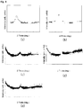
- FIG. 1 shows XRD graphs of Fe-based amorphous alloy powders according to the present invention, in which FIGS. 1a to 1e are XRD graphs of Fe-based amorphous alloy powders of Examples 1, 3, 6, 7, and 8, respectively.
- FIG. 1 it was found that each of Examples 1, 3, 6, 7, and 8 had a broad peak at a 2-Theta (2 ⁇ ) value of 40 to 50 degree angles, and each of which formed an amorphous phase.
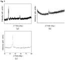
- FIG. 2 shows XRD graphs of Fe-based alloy powders according to Comparative Examples, in which FIGS. 2a to 2c are XRD graphs of Fe-based alloy powders of Comparative Examples 1, 5, and 7, respectively.
- FIG. 2 it was found that each of Comparative Examples 1, 5 and 7 had a first sharp peak at a 2-Theta (2 ⁇ ) value of 40 to 50 degree angles and an additional second peak at 65 to 70 degree angles at a minimum, and each of which formed some crystalline phase together with an amorphous phase.
- FIG. 3 SEM images of an Fe-based amorphous alloy powder (as atomized) according to Example 7 and the cross-section thereof, and an Fe-based alloy powder (as atomized) according to Comparative Example 7 and the cross-section thereof are shown.
- FIGS. 3a and 3b respectively show the Fe-based amorphous alloy powder (as atomized) of Example 7 and the cross-section thereof
- FIGS. 3c and 3d respectively show the Fe-based alloy powder (as atomized) of Comparative Example 7 and the cross-section thereof.
- FIG. 3b it was found that no structure was observed, thus showing a porosity of substantially 0%.
- FIG. 3d it was found that a number of structures were observed.
- FIG. 4 shows XRD graphs of coating samples according to the present invention, in which FIGS. 4a to 4e are XRD graphs of coating samples of Examples 9, 11, 14, 15, and 16 to which Fe-based amorphous alloy powders of Examples 1, 3, 6, 7, and 8 are applied, respectively.
- FIG. 4 shows XRD graphs of coating samples according to the present invention, in which FIGS. 4a to 4e are XRD graphs of coating samples of Examples 9, 11, 14, 15, and 16 to which Fe-based amorphous alloy powders of Examples 1, 3, 6, 7, and 8 are applied, respectively.
- FIG. 4 shows XRD graphs of coating samples according to the present invention, in which FIGS. 4a to 4e are XRD graphs of coating samples of Examples 9, 11, 14, 15, and 16 to which Fe-based amorphous alloy powders of Examples 1, 3, 6, 7, and 8 are applied, respectively.
- an additional peak is not present while a wide XRD first peak is present. Therefore, it was found that powders according to the present invention had an amorphous structure
- FIG. 5 XRD graphs of Fe-based alloy powder coating samples prepared in Comparative Examples are shown.
- FIG. 5 shows XRD graphs of coating samples of Comparative Examples, in which FIGS. 5a to 5c are XRD graphs of coating samples of Comparative Examples 8, 12, and 14 to which Fe-based alloy powders of Comparative Examples 1, 5, and 7 are applied, respectively.
- FIG. 5 in each of the Comparative Examples, an additional peak is present together with a sharp first peak. Therefore, it was found that powders according to the Comparative Examples were crystalline powders having no amorphous phase.
- the alloy powders according to the present invention had a much higher amorphous forming ability than the alloy powders according to the Comparative Examples.
- a coating is formed to entirely have a substantially amorphous phase (equal to or greater than 95% by volume) by HVOF spraying.
- FIG. 6 shows surface images of thermal sprayed coatings using Fe-based amorphous alloy powders according to the present invention and thermal sprayed coatings using alloy powders of Comparative Examples, in which FIGS. 6a to 6c are surface images of thermal sprayed coatings of Examples 9, 15, and 16 using Fe-based amorphous alloy powders of Examples 1, 7, and 8, respectively, and FIGS. 6d to 6g are surface images of thermal sprayed coatings of Comparative Examples 8, 10, 12, and 14 using alloy powders of Comparative Examples 1, 3, 5, and 7, respectively.
- FIG. 7 shows images of cross-sections of thermal sprayed coating samples using Fe-based amorphous alloy powders of Examples 1, 3, 6, and 8 according to the present invention, which are observed with an optical microscope (Leica DM4 M), in which FIGS. 7a to 7d are images of cross-sections of samples of Examples 9, 11, 14, and 16, respectively.
- FIG. 8 shows images of cross-sections of thermal sprayed coating samples using alloy powders of Comparative Examples 1, 4, and 7, which are observed with the optical microscope, in which FIGS. 8a to 8c are images of cross-sections of samples of Comparative Examples 8, 11, and 14, respectively.
- FIG. 7 it was found that the cross sections of the coating of Examples 9, 11, 14, and 16 all exhibited high density.
- a micro-hardness test for cross-sections of coating samples was performed on the thermal sprayed coatings of Examples 11, 14, and 16, and on the thermal sprayed coatings of Comparative Examples 8, 10, 12, and 14 using an HVS-10 Digital Low Load Vickers Hardness Tester, and the results are shown in Table 3 below.
- FIG. 9 shows images of uncorroded/corroded cross-sections of thermal sprayed coating samples using Fe-based amorphous alloy powders of Examples 2, 4, and 7 according to the present invention, which are observed with the optical microscope, in which FIGS. 9a to 9c are images of samples of Examples 10, 12, and 15, respectively.
- FIG. 10 shows images of uncorroded/corroded cross-sections of thermal sprayed coating samples using alloy powders of Comparative Examples 2, 4, and 6, which are observed with the optical microscope, in which FIGS. 10a to 10c are images of samples of Comparative Examples 8, 11, and 13, respectively.
- each of the thermal sprayed coating samples was immersed in a solution of sulfuric acid (H 2 SO 4 ) at a concentration of 95 to 98% for 5 minutes at room temperature. Then, the cross-sections of an uncorroded coating sample and a corroded coating sample, and the surfaces were observed with an optical microscope (Leica DM4 M). In FIGS. 9 and 10 , an uncorroded coating is shown on the left side, and a corroded coating is shown on the right side.
- H 2 SO 4 sulfuric acid
- the coating samples of alloy powder prepared in Examples 14 to 16 and Comparative Examples 11 to 14 were subjected to a metal ring-lump test under lubricant conditions to obtain wear width values.
- the ring-lump test was performed using MR-H3A high-speed ring-lump wear tester having L-MM 46 resistance friction hydromantic lubricant, under parameters of 50 N, 5 min ⁇ 100 N, 25 min ⁇ 1000 N, 55 min.
- Each of the golf clubs obtained in Preparation Example 2 and Preparation Example 4 was mounted on a ball trajectory analysis swing robot (Foresight GCQuad) with an ultra high-speed camera system, and a golf swing robot distance hitting test was performed under 90 mph & 95 mph conditions. Test items were ball speed, launch angle, backspin rate, side angle, carry, and total distance. The test was repeated five times, and the average values are shown in Tables 6 and 7 below.
Landscapes
- Chemical & Material Sciences (AREA)
- Engineering & Computer Science (AREA)
- Materials Engineering (AREA)
- Mechanical Engineering (AREA)
- Organic Chemistry (AREA)
- Metallurgy (AREA)
- Plasma & Fusion (AREA)
- Physics & Mathematics (AREA)
- Chemical Kinetics & Catalysis (AREA)
- Manufacturing & Machinery (AREA)
- Health & Medical Sciences (AREA)
- General Health & Medical Sciences (AREA)
- Physical Education & Sports Medicine (AREA)
- Wood Science & Technology (AREA)
- Life Sciences & Earth Sciences (AREA)
- Composite Materials (AREA)
- Structural Engineering (AREA)
- Civil Engineering (AREA)
- Ceramic Engineering (AREA)
- Golf Clubs (AREA)
- Powder Metallurgy (AREA)
- Coating By Spraying Or Casting (AREA)
- Manufacture Of Metal Powder And Suspensions Thereof (AREA)
Abstract
Description
- The present invention relates generally to a golf club and a method of manufacturing the same. More particularly, the present invention relates to a golf club and a method of manufacturing the same, whereby hardness of a surface of a clubhead is increased and repulsive and elastic forces are increased, thus increasing driving distance.
- In general, golf is an athletic sport in which players use golf clubs to hit a golf ball and hit the ball into a cup from a certain distance away, and unlike other sports, considerably high accuracy and mental power are required. In addition, unlike other sports, in golf, the direction and driving distance of the golf ball can be influenced by a golfer's posture during golf shots, a golf swing posture, and gripping of clubs. Golf clubs are largely classified into three types: drivers for increasing driving distance, irons for precise shots, and putters for hitting golf balls on the green. Most are made of high-strength metal such as titanium. In particular, in the case of drivers, for a long driving distance, human factors such as posture and speed, and repulsive force depending on the material and characteristics of the drivers (in particular, the face of a club) are important.
- For this reason, attempts have been made to change composition of the face of a clubhead among components constituting a driver. For example, efforts have been made to improve an elastic force of golf clubs by researching and developing a technique of changing the surface material of the face of the clubhead, or a technique of changing the internal structure of the face of the clubhead, such as incorporating a separate member thereinside.
- However, in the former case, the clubface may be damaged or there is a limit in improving the elastic force. In the latter case, it may be troublesome because this is a mechanism that requires the separate member to be incorporated inside the clubface. In addition, the incorporated member may be damaged after a long-term use, causing difficulty in using the driver and a reduction in the repulsive force. Therefore, there is a need to develop a new clubface that can improve performance of a golf club, such as repulsive force.
- (Patent document 1)
U.S. Patent Application Publication No. 3,102,187 - An objective of the present invention is to provide a golf club, whereby a clubface provided on a side of a clubhead includes a base part, and a coating layer provided on a surface of the base part and including an Fe-based amorphous alloy, thus ensuring that surface hardness, and repulsive and elastic forces of a surface of the clubhead are improved.
- Another objective of the present invention is to provide a method of manufacturing a golf club, whereby a coating layer including an Fe-based alloy having a high proportion of amorphous phase is coated on a surface of a base part of a clubface provided on a side of a clubhead.
- In order to achieve the above objective, according to one aspect of the present invention, there is provided a golf club, including: a clubhead; and a shaft connected to the clubhead, wherein the clubhead includes a clubface provided on a side thereof, and the clubface includes: a base part; and a coating layer provided on a surface of the base part and including an Fe-based amorphous alloy.
- According to another aspect of the present invention, there is provided a method of manufacturing a golf club, the method including: forming a coating layer including an Fe-based amorphous alloy on a surface of a base part of a clubface provided on a side of a clubhead; and polishing the coating layer, wherein a proportion of an amorphous phase in the coating layer is 90 to 100%.
- According to the golf club according to the embodiments of the present invention, the Fe-based amorphous alloy layer is coated on the surface of the base part of the clubface provided on a side of the clubhead, thus ensuring that the amorphous structure is maintained after coating. Therefore, the present invention has an advantage in that the surface hardness, elastic force, and the like of the surface of clubhead are improved, thus realizing significant improvement in the driving distance of a golf ball. The coating layer of the Fe-based amorphous alloy formed herein can maintain a high amorphous phase proportion.
- Furthermore, according to the method of manufacturing the golf club according to the embodiments of the present invention, the shape and thickness of the base part of the clubface provided on a side of the clubhead are controlled to be reduced to a limit level, while reducing the thickness of the Fe-based amorphous alloy layer. Therefore, the present invention has an advantage in maximizing a repulsive force.
-
-
FIG. 1 shows XRD graphs of Fe-based amorphous alloy powders according to the present invention used as a coating material on a clubface, in whichFIGS. 1A to 1E are XRD graphs of Fe-based amorphous alloy powders of Examples 1, 3, 6, 7, and 8, respectively. -
FIG. 2 shows XRD graphs of Fe-based alloy powders according to Comparative Examples used as the coating material on the clubface, in whichFIGS. 2a to 2c are XRD graphs of Fe-based alloy powders of Comparative Examples 1, 5, and 7, respectively. -
FIG. 3 shows SEM images, in whichFIGS. 3A and 3B are SEM images of an Fe-based amorphous alloy powder of Example 7 used as the coating material on the clubface and a cross-section thereof, respectively, andFIGS. 3c and 3d are SEM images of an Fe-based alloy powder of Comparative Example 7 used as the coating material on the clubface and a cross-section thereof, respectively. -
FIG. 4 shows XRD graphs of coating samples according to the present invention applied to the clubface, in whichFIGS. 4a to 4e are XRD graphs of coating samples of Examples 9, 11, 14, 15, and 16 to which Fe-based amorphous alloy powders of Examples 1, 3, 6, 7, and 8 are applied, respectively. -
FIG. 5 shows XRD graphs of coating samples of Comparative Examples applied to the clubface, in whichFIGS. 5a to 5c are XRD graphs of coating samples of Comparative Examples 8, 12, and 14 to which Fe-based alloy powders of Comparative Examples 1, 5, and 7 are applied, respectively. -
FIG. 6 shows surface images of thermal sprayed coatings using Fe-based amorphous alloy powders according to the present invention coated on the clubface and thermal sprayed coatings using alloy powders of Comparative Examples coated on the clubface, in whichFIGS. 6a to 6c are surface images of thermal sprayed coatings using Fe-based amorphous alloy powders of Examples 1, 7, and 8, respectively, andFIGS. 6d to 6g are surface images of thermal sprayed coatings using alloy powders of Comparative Examples 1, 3, 5, and 7, respectively. -
FIG. 7 shows images (200x magnification) of cross-sections of thermal sprayed coating samples using Fe-based amorphous alloy powders of Examples 1, 3, 6, and 8 according to the present invention as the coating material on the clubface, which are observed with an optical microscope, in whichFIGS. 7a to 7d are images of cross-sections of samples of Examples 9, 11, 14, and 16, respectively. -
FIG. 8 shows images (200x magnification) of cross-sections of thermal sprayed coating samples using alloy powders of Comparative Examples 1, 4, and 7 as the coating material on the clubface, which are observed with the optical microscope, in whichFIGS. 8a to 8c are images of cross-sections of samples of Comparative Examples 8, 11, and 14, respectively. -
FIG. 9 shows images (200x magnification) of uncorroded/corroded cross-sections of thermal sprayed coating samples using Fe-based amorphous alloy powders of Examples 2, 4, and 7 according to the present invention as the coating material on the clubface, which are observed with the optical microscope, in whichFIGS. 9a to 9c are images of samples of Examples 10, 12, and 15, respectively. -
FIG. 10 shows images (200x magnification) of uncorroded/corroded cross-sections of thermal sprayed coating samples using alloy powders of Comparative Examples 2, 4, and 6 as the coating material on the clubface, which are observed with the optical microscope, in whichFIGS. 10a to 10c are images of samples of Comparative Examples 8, 11, and 13, respectively. -
FIG. 11 shows embodiments of the present invention, in whichFIG. 11a is a photogragh of a clubhead of a golf club produced according to the embodiments of the present invention, andFIG. 11b is a view schematically showing a form in which an Fe-based amorphous alloy layer is coated on a base part of a clubface. - Hereinafter, the present invention will be described in detail.
- In the present specification, "amorphous" refers to a phase (also used as a non-crystalline or amorphous phase) which lacks the long range order of a crystal, e.g., which does not have a crystalline structure.
- Furthermore, in the present specification, "coating layer" includes a coating film and the like made using an Fe-based amorphous alloy powder, and which are mainly made by thermal spraying.
- Furthermore, in the present specification, "Fe-based amorphous alloy powder" refers an alloy powder in which iron is contained at the highest weight ratio, and an amorphous phase is not simply contained in the powder, but substantially occupies most of the powder, for example, the amorphous phase is contained in a proportion of equal to or greater than 90%.
- As described above, in golf where very high accuracy is required unlike other sports, the material of a golf club for improving driving distance is particularly important. For this reason, attempts have been made to improve an elastic force of the golf club by changing the surface material of a clubface provided on a side of a clubhead. However, the surface of the clubface may be damaged, or, even if not damaged, there is a limit in improving the elastic force. This causes difficulty in development of a golf club having a further improved performance. Accordingly, the present applicant has developed a new golf club that can improve performance such as repulsive force compared with the related art.
- A clubface having an amorphous surface according to the present invention may be obtained by coating an Fe-based amorphous alloy according to the present invention on the surface of a base part of a pre-made (ready-made) clubface (even when the Fe-based amorphous alloy according to the present invention is coated, it is limited to a thickness level that is not unreasonable for achieving the objective of the present invention). Alternatively, the clubface having the amorphous surface according to the present invention may be obtained by reducing the thickness of the base part of the pre-made clubface to a limit level (i.e., thinning of a conventional material for coating), and then coating the surface of the base part with the Fe-based amorphous alloy.
- That is, a golf club according to the present invention is a golf club including a clubhead and a shaft connected to the clubhead. The clubhead includes a clubface provided on a side thereof, and the clubface includes: a base; and a coating layer provided on the surface of the base part and including an Fe-based amorphous alloy.
- A golf club according to an aspect of the present invention includes a base part of a clubhead, and a coating layer formed on the base.
- The base part of the clubhead refers to a term referring to a typical face (hitting part) located on a side of the clubhead.
- When an Fe-based amorphous alloy powder is coated on the base part of the clubface, there is a fear that the repulsive force at the time of hitting may not reach a desired level. Therefore, it is preferable that the shape and thickness of the base part of the clubface is controlled.
- The thickness of the base part of the clubface may be 1.4 to 2.6 mm, preferably 1.6 to 2.4 mm, in consideration of the coating thickness of the Fe-based amorphous alloy. When the thickness of the base part is less than 1.4 mm, the thickness of a base material constituting the clubface is excessively reduced beyond the limit value, and thus a basic performance of the clubface may be degraded. On the other hand, when the thickness of the base part is greater than 2.6 mm, a total thickness of the base material and the Fe-based amorphous alloy is excessively increased, and thus the repulsive force at the time of hitting may not reach the desired level.
- The shape of the base part of the clubface is planar in the case of irons, and in the case of drivers and woods, it is preferable that at least a part of a central portion of the base part has a convex shape as compared with remaining parts. When the thickness of the central portion is 1.8 mm, the thickness of a peripheral portion may be about 1.6 mm, when the thickness of the central portion is 2.2 mm, the thickness of the peripheral portion may be about 2.0 mm, and when the thickness of the central portion is 2.6 mm, the thickness of the peripheral portion may be about 2.4 mm.
- In order to control the thickness and shape of the base part, for example, a method or equipment such as mold thickness control or CNC milling may be used. Herein, it may be more preferable that the thickness of the base part is controlled by controlling the mold thickness.
- In order to prevent durability degradation that may occur due to the base part having a reduced thickness, a surface treatment process including forging that can densify the surface structure of the base part may be performed to improve mechanical properties such as strength, toughness, and durability.
- Meanwhile, a material of the base part may be selected from the group consisting of Ti, Al, V, Mo, Fe, Cr, Sn, and Zr, and an alloy containing at least two thereof, and also face materials of all the golf clubs currently manufactured in the related art may be used.
- The hardness of the base part may be HV 300 to HV 400, preferably HV 340 to HV 360.
- Hereinafter, the coating layer, which is provided on the surface of the base part of the clubface and made of the Fe-based amorphous alloy, will be described.
- The coating layer is a layer provided on the clubface to provide high repulsion, elasticity, and hardness. The coating layer is formed on the base part to occupy equal to greater than 60% of the area of the surface of the base part.
- The Fe-based amorphous alloy used to form the coating layer refers an alloy in which iron, chromium, and molybdenum are contained as a main component, and an amorphous phase is not simply contained in powder, but substantially occupies most of the powder, for example, the amorphous phase is contained in a proportion of equal to or greater than 90%, or 90 to 100%.
- The coating layer may be formed by spraying a molten Fe-based amorphous alloy powder on the surface of the base part.
- The coating layer may be formed by cooling the molten Fe-based amorphous alloy powder from a melting point to a glass transition temperature at a cooling rate of 101 to 104 (degree/sec) after spraying.
- It is preferable that the Fe-based amorphous alloy is provided from an Fe-based amorphous alloy powder containing iron, chromium, and molybdenum and further at least one selected from carbon and boron.
- Herein, the Fe-based amorphous alloy powder is, for example, a powder having a high amorphous phase proportion, such as when an amorphous phase is contained in a proportion of equal to or greater than 90%, equal to or greater than 95%, equal to or greater than 99%, equal to or greater than 99.9%, or substantially 100% when prepared by atomizing.
- The Fe-based amorphous alloy powder may be prepared in a variety of shapes and diameters without being limited thereto. The Fe-based amorphous alloy powder includes a first component, a second component, a third component, and a fourth component that are used for making the Fe-based amorphous alloy described above.
- The first component is iron (Fe). Iron (Fe) is a component used to improve the rigidity of an alloy powder coating. The second component is chromium (Cr) used to improve the physical properties of the alloy powder coating, such as wear resistance, corrosion resistance, and the like. The second component may be contained in an amount of equal to or less than 55.3 parts by weight per 100 parts by weight of the first component, preferably 25.4 to 55.3 parts by weight.
- The third component is molybdenum (Mo) used to impart the wear resistance, corrosion resistance, and friction resistance. The third component may be contained in an amount of equal to or less than 84.2 parts by weight per 100 parts by weight of the first component, preferably 35.6 to 84.2 parts by weight.
- The fourth component uses at least one or two of carbon (C) and boron (B). The fourth component is used to improve the amorphous forming ability by atomic size mismatch with the other components, packing ratio efficiency, or the like. It is preferable that the fourth component is contained in an amount of equal to or less than 23.7 parts by weight, 1.7 to 23.7 parts by weight, 3.4 to 23.7 parts by weight, or 3.4 to 15 parts by weight, per 100 parts by weight of the first component.
- In addition to the above-described components, the Fe-based amorphous alloy powder may intentionally or unintentionally include additional components selected from the group consisting of tungsten, cobalt, yttrium, manganese, silicon, aluminum, niobium, zirconium, phosphorus, nickel, scandium, and a mixture thereof. In terms of amount of the additional components, the additional components are contained in a total amount of less than 1.125 parts by weight, equal to or less than 1.000 parts by weight, or equal to or less than 0.083 parts by weight, per 100 parts by weight of iron. That is, when the amounts of the first component, the second component, the third component, the fourth component, and the additional components fulfill the above-described weight proportions, this case is regarded as an Fe-based alloy powder according to the present invention.
- Furthermore, each of the additional components is contained in an amount of equal to or less than 0.9 parts by weight, preferably equal to or less than 0.05 parts by weight. This is because when the amount of the additional component is outside such a range, the amorphous forming ability is significantly reduced. The Fe-based amorphous alloy powder has excellent properties such as density, strength, wear resistance, friction resistance, and corrosion resistance due to the high amorphous phase proportion.
- The Fe-based amorphous alloy powder prepared according to embodiments of the present invention may have an average particle size in a range of 1 to 150 µm, but is not limited thereto. The powder size thereof may be controlled by sieving depending on uses.
- For example, when thermal spraying is to be performed as will be described later, a target Fe-based amorphous alloy powder may be used after controlling the powder size in a range of 16 to 54 µm by sieving. When metal powder injection molding (MIM) is to be performed, the target Fe-based amorphous alloy powder may be used after controlling the powder size to be equal to or less than 20 µm by sieving.
- Furthermore, when three-dimensional (3D) printing is to be performed, the powder size of the target Fe-based amorphous alloy powder may be controlled depending on 3D printing methods. For example, when 3D printing is to be performed by a powder bed fusion method, the powder size may be controlled to be equal to or less than 20 µm, and when 3D printing is to be performed by a direct energy deposit method, the powder size may be controlled to be in a range of 54 to 150 µm.
- The Fe-based amorphous alloy powder may have a density, for example, in a range of about 7±0.5 g/cc, but is not limited thereto.
- The Fe-based amorphous alloy powder may have a hardness in a range of about 800 to 1500 Hv, but is not limited thereto.
- The Fe-based amorphous alloy powder is characterized by maintaining the above-described proportion of the amorphous phase even when re-melted or when exposed to high temperature and recooled for solidification. Herein, proportion a of the amorphous phase in the Fe-based amorphous alloy powder prepared by atomizing and proportion b of an alloy made by melting the Fe-based amorphous alloy powder above the melting point of the alloy and then re-cooling the same fulfill the following equation.

- Here, examples of a method of making an alloy by melting the Fe-based amorphous alloy powder above the melting point of the alloy and then re-cooling the same in order to derive the b may include thermal spraying, 3D printing, and a known casting method such as metallurgy.
- In addition, the ratio of b/a of the Equation 1 may be preferably 0.95 to 1, more preferably 0.98 to 1, and more preferably 0.99 to 1.
- As described above, the coating layer may be formed by thermal spraying. Thermal spraying is a technique whereby a metal or metal compound is melted into fine droplets and sprayed onto a surface of an object to come into close contact with the surface, but the formation of the coating layer is not limited to a specific method of thermal spraying. Examples of thermal spraying used to form the coating layer may include high velocity oxygen fuel (HVOF) spraying, plasma spraying, laser cladding, general flame spraying, diffusion, cold spraying, vacuum plasma spraying (VPS), low-pressure plasma spraying (LPPS), and the like.
- In the present specification, when the Fe-based amorphous alloy powder, which has a high amorphous phase proportion, such as when an amorphous phase is contained in a proportion of equal to or greater than 90%, equal to or greater than 95%, equal to or greater than 99%, equal to or greater than 99.9%, or substantially 100%, is used as a thermal spraying material, the coating layer contains an amorphous phase in a proportion of equal to or greater than 90%, equal to or greater than 95%, equal to or greater than 99%, equal to or greater than 99.9%, or substantially 100% by volume of the total structure, thus having very excellent physical properties. Particularly, when HVOF spraying is performed using the alloy powder according to the present invention, the degree of improvement of physical properties is maximized because the proportion of the amorphous phase is substantially maintained.
- Furthermore, the Fe-based amorphous alloy powder exhibits a very high coating density of 98 to 99.9% upon measurement, which has an advantage in suppressing penetration of corrosives through pores.
- The Fe-based amorphous alloy powder used in thermal spraying has a particle size of 10 to 100 µm, preferably 15 to 55 µm. This is because when the alloy powder has a particle size of less than 10 µm, small particles may adhere to a spraying gun during a spray coating process, which may contribute to a reduction in operating efficiency. Further, this is also because when the alloy powder has a particle size of greater than 100 µm, the alloy powder may collide with a base metal without being completely dissolved (i.e., may fall to the bottom without forming a coating), resulting in a reduction in coating productivity and efficiency.
- Meanwhile, the Vickers hardness of the Fe-based amorphous alloy is 700 to 1,200 Hv (0.2), preferably 800 to 1,000 Hv (0.2), and the friction coefficient (friction resistance) is 0.001 to 0.08 µ, preferably equal to or less than 0.05 µ at a load of 100 N, and is 0.06 to 0.12 µ, preferably equal to or less than 0.10 µ at a load of 1,000 N.
- Particularly, in the case of a coating made by HVOF spraying, unlike the related art, there are almost no pores present in the cross-section, and thus the coating exhibits a full density. On the contrary, even when the pores are present, a porosity of only about 0.1 to 1.0% is exhibited.
- That is, when HVOF spraying is performed, a structure in which multiple paths are stacked is formed. In detail, oxides (black color) are accumulated on each layer, and multiple layers are stacked in a wave-like shape. While this usually causes the properties of a coating to be degraded and weakened, in the present invention, the coating has no pore/oxidation film, thus ensuring that the coating exhibits ultra-high density, and the performance thereof is improved. Moreover, it is possible that the coating layer including the Fe-based amorphous alloy powder exhibits improved wear resistance, corrosion resistance, and elasticity, which are advantageous over a case using an alloy powder in the related art.
- Furthermore, the thickness of the coating layer of the Fe-based amorphous alloy coated on the base part is 0.01 to 0.3 mm, preferably 0.1 to 0.2 mm, and more preferably 0.075 to 0.125 mm. This is because when the thickness of the coating layer of the Fe-based amorphous alloy is outside such a range, a desired repulsive force of the clubface of the present invention may not be achieved.
- Meanwhile, the Fe-based amorphous alloy may be coated on the entire surface of the base part, or may be coated only on a portion of the surface in a hitting direction. However, the Fe-based amorphous alloy may occupy equal to or greater than 60% of the total area of the surface of the base part of the clubface, preferably 70 to 95%, and more preferably 75 to 90%. In this case, it is possible that the driving distance of a golf ball hit in a corresponding area when the golf ball is hit on the clubface.
- In addition, the Fe-based amorphous alloy may be formed in various patterns such as a lattice pattern as necessary.
- Meanwhile, the Fe-based amorphous alloy powder as a raw material of the Fe-based amorphous alloy is prepared using a gas atomizer. In detail, the Fe-based amorphous alloy powder is prepared by spray cooling in a molten state in the atomizer under the atmosphere of inert gas such as helium, nitrogen, neon, argon or the like. When prepared in this way, it is possible that a powder having a high purity amorphous phase is prepared.
- Next, the physical properties of the coating layer of the Fe-based amorphous alloy formed on the surface of the base part will be described. The Vickers hardness of the coating layer of the Fe-based amorphous alloy is 700 to 1,200 Hv (0.2), preferably 800 to 1,000 Hv (0.2), and the friction coefficient (friction resistance) is 0.0005 to 0.08 µ, preferably 0.001 to 0.05 µ at a load of 100 N, and is 0.01 to 0.12 µ, preferably 0.03 to 0.10 µ at a load of 1,000 N. The coefficient of restitution (COR) of the golf club to which the coating layer of the Fe-based amorphous alloy is applied indicates a high repulsion of equal to or greater than 0.83.
- Furthermore, in the case of a coating layer made by HVOF spraying, unlike the related art, there are almost no pores present in the cross-section, and thus the alloy exhibits a full density of 99 to 100%, preferably 99.5 to 100%, and more preferably 99.8 to 100%. On the contrary, even when the pores are present, a porosity of only about 0.2 to 1.0% is exhibited.
- That is, when HVOF spraying is performed, a structure in which multiple paths are stacked is formed. In detail, oxides (black color) are accumulated on each layer, and multiple layers are stacked in a wave-like shape. While this usually causes the properties of a coating layer to be degraded and weakened, in the present invention, an alloy layer (coating) has no pore/oxidation film, thus exhibiting ultra-high density, and also improving physical properties such as hardness, corrosion resistance, and wear resistance. Meanwhile, the clubface according to the present invention has a shape of a typical clubface, and there is no particular limitation on the size or shape thereof.
- Hereinafter, a method of manufacturing a golf club according to the present invention will be described.
- The method of manufacturing the golf club according to the present invention includes: forming a coating layer including an Fe-based amorphous alloy powder on the surface of a base part of a clubface provided on a side of a clubhead; and polishing the coating layer.
- In forming the coating layer, the coating layer may be formed by thermal spraying. The formation of the coating layer may be performed by any method known in the art, and the conditions and the environment thereof may also be similar to those in the art. For example, a method whereby a Sulzer Metco Diamond Jet or similar equipment is used, and oxygen flow, propane flow, air flow, feeder rate, nitrogen flow, and the like are appropriately controlled may be adopted.
- In detail, the thermal spraying is performed in such a manner that the Fe-based amorphous alloy powder is melted and then sprayed onto the surface of the base part. The thermal spraying may be performed by a method selected from the group consisting of HVOF spraying, plasma spraying, vacuum plasma spraying, and wire arc spraying.
- In forming the coating layer, the Fe-based amorphous alloy is configured such that proportion a of an amorphous phase in an alloy powder and proportion (b) of the amorphous phase in a coating layer fulfills an equation of 0.9 ≤ b/a ≤ 1, the alloy powder being prepared by melting an Fe-based amorphous alloy powder containing iron, chromium, and molybdenum and further containing at least one of carbon and boron and then cooling the melted Fe-based amorphous alloy powder from a melting point to a glass transition temperature at a cooling rate of 101 to 104 (degree/sec), and the coating layer being prepared by re-melting the alloy powder and cooling the re-melted alloy powder from a melting point to a glass transition temperature at the cooling rate of 101 to 104 (degree/sec). In addition, the ratio of b/a may be preferably 0.95 to 1, more preferably 0.98 to 1, and more preferably 0.99 to 1.
- The melted alloy powder is characterized in that even when the melted alloy powder is sprayed and cooled from a melting point to a glass transition temperature at a cooling rate of 102 to 103 or 101 to 104 (degree/sec), the amorphous phase is contained in the coating layer in a high proportion of equal to or greater than 90%, equal to or greater than 95%, equal to or greater than 99%, equal to or greater than 99.9%, or substantially 100% by volume.
- When the thermal spraying is performed, a structure in which multiple paths are stacked is formed. In detail, oxides (black color) are accumulated on each layer, and multiple layers are stacked on the plate in a wave-like shape. While this usually causes the properties of the coating layer to be degraded and weakened, in the present invention, an alloy layer (coating layer) has no pore/oxidation film, thus exhibiting ultra-high density, and also improving physical properties such as hardness, corrosion resistance, and wear resistance.
- In polishing the coating layer, the Fe-based amorphous alloy powder is subjected to thermal spraying to form the coating layer with a predetermined thickness, and then the surface of the coating layer is polished to reduce the thickness. That is, reducing the thickness of the surface of the coating layer formed by thermal spraying allows only a densely coated portion to remain on the clubface. For example, a 0.1 mm coating layer is formed by thermal spraying, polished to a thickness of about 0.025 mm, and finally a 0.075 mm coating layer is formed on the surface of the clubface.
- Meanwhile, the method may further include before forming the coating layer, controlling the shape, strength, and thickness of the base part of the clubface. In order to control the thickness and shape of the base part, for example, a method or equipment such as mold thickness control or CNC milling may be used. Herein, it may be more preferable that the thickness of the base part is controlled by controlling the mold thickness.
- In order to prevent durability degradation that may occur due to the base part having a reduced thickness, a surface treatment process including forging that can densify the surface structure of the base part may be performed to improve mechanical properties such as strength, toughness, and durability.
- The present invention provides a golf club including a clubhead having the clubface provided on a side thereof, a shaft coupled to one end of the clubhead, and a grip part provided at an end of the shaft not connected to the clubhead. All the remaining parts except the clubface, such as the shaft, the clubhead, and the like, may use any known equipment in the art.
- The present invention is to manufacture a new clubface by coating a high-repulsion, high-hardness, high-elasticity, low-friction amorphous alloy (having more than twice the hardness of a typical clubface material) to a clubface made of the typical material, whereby it is possible that the objective of the present invention to increase the driving distance by improving the ball speed, reducing the spin rate, and increasing the launch angle is achieved.
- Hereinbelow, to aid to understanding the invention, exemplary embodiments of the present invention will be described. It should be understood that the embodiments of the present invention are only examples of the invention and those skilled in the art will appreciate that various modifications, additions and substitutions are possible, without departing from the scope and spirit of the invention as disclosed in the accompanying claims.
- Powders containing compositions having the components and weight ratio as shown in Table 1 below were fed into an atomizer under a nitrogen gas atmosphere, and then atomized in a molten state and cooled at a cooling rate shown in Table 1 below, whereby Fe-based amorphous alloy powders of Examples 1 to 8 were prepared.
Table Classification Example 1 Example 2 Example 3 Example 4 Example 5 Example 6 Example 7 Example 8 Fe 1 1 1 1 1 1 1 1 Cr 0.55 0.26 0.355 0.292 0.374 0.355 0.292 0.374 Mo 0.84 0.36 0.645 0.502 0.411 0.645 0.502 0.411 C 0.06 - 0.092 - .056 0.092 0.080 0.056 B - 0.04 - 0.04 - 0.1 0.092 0.04 Cooling rate (degree/sec) 104 104 104 103 103 102 102 102 * Powder average diameter 5 5 10 20 20 50 50 50 * D50 (unit: µm) - As can be seen from Table 1, the Examples according to the present invention contained the first to fourth components in a specific amount range and were cooled at a cooling rate of 101 to 104 (degree/sec) to prepare alloy powders having a powder average diameter of 5 to 50 µm.
- Clubfaces (base part, material: Ti) of typical (bare) clubheads were reduced in thickness by use of CNC milling to obtain a clubface with a thickness of 1.8 mm at a central portion and 1.6 mm at a peripheral portion, a clubface with a thickness of 2.2 mm at a central portion and 2.0 mm at a peripheral portion, and a clubface with a thickness of 2.6 mm at a central portion and 2.4 mm at a peripheral portion.
- The Fe-based amorphous alloy powders of Examples 1 to 8 each of which was coated on the surface of a base part of each of the clubfaces obtained in Preparation Example 1 to a thickness of 0.1 mm by thermal spraying to manufacture clubfaces each having an Fe-based amorphous alloy layer.
- In detail, coatings having a thickness of 0.3 mm were formed. Oerlikon Metco Diamond Jet series HVOF gas fuel spray system was used, fuel was oxygen and propane gas, and high velocity oxygen fuel (HVOF) was used, with a spray distance of 30 cm. The device and specific conditions used herein are as follows.
- [Condition] Gun type: Hybrid, Air cap: 2701, LPG flow: 160 SCFH, LPG pressure: 90 PSI, Oxygen flow: 550 SCFH, Oxygen pressure: 150 PSI, Air flow: 900 SCFH, Air pressure: 100 PSI, Nitrogen flow: 28 SCFH, Nitrogen pressure: 150 PSI, Gun speed: 100 m/min, Gun pitch: 3.0mm, Feeder rate 45 g/min, Stand-off distance: 250 mm
- The Fe-based amorphous alloy layer on the surface of a base part formed on a side of each of the clubfaces obtained from Examples 9 to 16 was polished by 0.025 mm. Then, each of the clubfaces was attached to a clubhead to manufacture typical golf clubs each having a shaft and a grip part connected to each other.
- A photograph of the clubface manufactured from Example 9 is shown in
FIG. 11a . Herein, a form in which the Fe-based amorphous alloy layer is coated on the surface of the base part of the clubface is schematically shown inFIG. 11b . Referring toFIG. 11b , the Fe-based amorphous alloy layer is formed to occupy about 80% of the total area of the surface the base part, based on the central portion. This case is advantageous in increasing the driving distance, which was found from Test Example 8 below. - Powders containing compositions having the components and weight ratio as shown in Table 2 below were fed into an atomizer under a nitrogen gas atmosphere, and then atomized in a molten state and cooled at a cooling rate shown in Table 2 below, whereby Fe-based alloy powders of Comparative Examples 1 to 7 were prepared.
Table 2 Classification Comparative example 1 Comparative example 2 Comparative example 3 Comparative example 4 Comparative example 5 Comparative example 6 Comparative example 7 Fe 1 1 1 1 1 1 1 Cr 0.56 0.20 0.714 0.714 0.550 0.411 0.196 Mo 0.30 0.85 0.345 0.245 0.183 0.374 0.686 C - - 0.020 0.060 0.028 0.028 0.020 B - 0.04 - - 0.073 0.056 0.059 Cooling rate (degree/sec) 104 104 104 103 102 102 102 * Powder average diameter 5 5 10 20 50 50 50 * D50 (unit: µm) - As can be seen from Table 2, the Comparative Examples according to the present invention contained the first to fourth components in a specific amount range and were cooled at a cooling rate of 101 to 104 (degree/sec) to prepare alloy powders having a powder average diameter of 5 to 50 µm.
- A clubface, which is typically used and is made of a material the same as that of the bare clubface of Preparation Example 1, with a thickness of 3.0 mm, was obtained (i.e., not coated with an Fe-based amorphous alloy powder).
- The alloy powder of Comparative Examples 1 to 7 each of which was coated on the surface of a base part of the clubface obtained in Preparation Example 3 by thermal spraying to a thickness of 0.1 mm in the same manner as in Examples to manufacture a clubface having a coating layer.
- The clubface of Preparation Example 3 was attached to a clubhead to manufacture a typical golf club having a shaft and a grip part connected to each other. Hereinafter, the case of using the golf club of Preparation Example 3 is referred to as Comparative Example 15 for convenience.
- Furthermore, the Fe-based amorphous alloy layer on the surface of a base part formed on a side of the clubface manufactured from Comparative Examples 8 to 14 was polished by 0.025 mm. Then, the clubface was attached to a clubhead to manufacture a typical golf club having a shaft and a grip part connected to each other.
- XRD measurement results for Fe-based amorphous alloy powders of Examples were shown in
FIG. 1. FIG. 1 shows XRD graphs of Fe-based amorphous alloy powders according to the present invention, in whichFIGS. 1a to 1e are XRD graphs of Fe-based amorphous alloy powders of Examples 1, 3, 6, 7, and 8, respectively. As shown inFIG. 1 , it was found that each of Examples 1, 3, 6, 7, and 8 had a broad peak at a 2-Theta (2θ) value of 40 to 50 degree angles, and each of which formed an amorphous phase. - Furthermore, XRD measurement results for Fe-based amorphous alloy powders of Comparative Examples were shown in
FIG. 2. FIG. 2 shows XRD graphs of Fe-based alloy powders according to Comparative Examples, in whichFIGS. 2a to 2c are XRD graphs of Fe-based alloy powders of Comparative Examples 1, 5, and 7, respectively. As shown inFIG. 2 , it was found that each of Comparative Examples 1, 5 and 7 had a first sharp peak at a 2-Theta (2θ) value of 40 to 50 degree angles and an additional second peak at 65 to 70 degree angles at a minimum, and each of which formed some crystalline phase together with an amorphous phase. - Particularly, considering the height of the second peak, it was found that the number of crystalline phases increased sequentially from Comparative Example 7, Comparative Example 5, to Comparative Example 1, i.e., from
FIG. 2c to FIG. 2a . - In
FIG. 3 , SEM images of an Fe-based amorphous alloy powder (as atomized) according to Example 7 and the cross-section thereof, and an Fe-based alloy powder (as atomized) according to Comparative Example 7 and the cross-section thereof are shown.FIGS. 3a and 3b respectively show the Fe-based amorphous alloy powder (as atomized) of Example 7 and the cross-section thereof, andFIGS. 3c and 3d respectively show the Fe-based alloy powder (as atomized) of Comparative Example 7 and the cross-section thereof. - As shown in
FIG. 3b , it was found that no structure was observed, thus showing a porosity of substantially 0%. On the other hand, as shown inFIG. 3d , it was found that a number of structures were observed. - Furthermore, in
FIG, 4 , amorphous XRD graphs of Fe-based amorphous alloy powder coating samples prepared in Examples 9 to 16 are shown.FIG. 4 shows XRD graphs of coating samples according to the present invention, in whichFIGS. 4a to 4e are XRD graphs of coating samples of Examples 9, 11, 14, 15, and 16 to which Fe-based amorphous alloy powders of Examples 1, 3, 6, 7, and 8 are applied, respectively. Referring toFIG. 4 , in each of the Examples, an additional peak is not present while a wide XRD first peak is present. Therefore, it was found that powders according to the present invention had an amorphous structure. - Furthermore, in
FIG. 5 , XRD graphs of Fe-based alloy powder coating samples prepared in Comparative Examples are shown.FIG. 5 shows XRD graphs of coating samples of Comparative Examples, in whichFIGS. 5a to 5c are XRD graphs of coating samples of Comparative Examples 8, 12, and 14 to which Fe-based alloy powders of Comparative Examples 1, 5, and 7 are applied, respectively. Referring toFIG. 5 , in each of the Comparative Examples, an additional peak is present together with a sharp first peak. Therefore, it was found that powders according to the Comparative Examples were crystalline powders having no amorphous phase. - That is, it was found from such results that the alloy powders according to the present invention had a much higher amorphous forming ability than the alloy powders according to the Comparative Examples.
- As a result of comparison between the XRD graphs of
FIG. 1 and the XRD graphs ofFIG. 3 , as shown inFIG. 3 , it was found that in all of the Examples, the amorphous structure of the powder was maintained even in the coating. - Particularly, in the case of the present test example, it was found that that a coating is formed to entirely have a substantially amorphous phase (equal to or greater than 95% by volume) by HVOF spraying.
-
FIG. 6 shows surface images of thermal sprayed coatings using Fe-based amorphous alloy powders according to the present invention and thermal sprayed coatings using alloy powders of Comparative Examples, in whichFIGS. 6a to 6c are surface images of thermal sprayed coatings of Examples 9, 15, and 16 using Fe-based amorphous alloy powders of Examples 1, 7, and 8, respectively, andFIGS. 6d to 6g are surface images of thermal sprayed coatings of Comparative Examples 8, 10, 12, and 14 using alloy powders of Comparative Examples 1, 3, 5, and 7, respectively. - As a result of evaluation, it was found that the coating of Comparative Example 14 had poor coating surface quality (see
FIG. 6g ), and the coatings of the remaining Examples and Comparative Examples all had excellent or good coating surface quality. -
FIG. 7 shows images of cross-sections of thermal sprayed coating samples using Fe-based amorphous alloy powders of Examples 1, 3, 6, and 8 according to the present invention, which are observed with an optical microscope (Leica DM4 M), in whichFIGS. 7a to 7d are images of cross-sections of samples of Examples 9, 11, 14, and 16, respectively.FIG. 8 shows images of cross-sections of thermal sprayed coating samples using alloy powders of Comparative Examples 1, 4, and 7, which are observed with the optical microscope, in whichFIGS. 8a to 8c are images of cross-sections of samples of Comparative Examples 8, 11, and 14, respectively. As shown inFIG. 7 , it was found that the cross sections of the coating of Examples 9, 11, 14, and 16 all exhibited high density. - On the other hand, as shown in
FIG. 8 , it was found that the cross-sections of the coatings of Comparative Examples 8, 11, and 14 not only contained a number of unmelted particles but also contained a number of gray phases, and layer-layer characteristics were exhibited. - A micro-hardness test for cross-sections of coating samples was performed on the thermal sprayed coatings of Examples 11, 14, and 16, and on the thermal sprayed coatings of Comparative Examples 8, 10, 12, and 14 using an HVS-10 Digital Low Load Vickers Hardness Tester, and the results are shown in Table 3 below.
Table 3 Classification area Test value HV0.2 Average HV0.2 Example 11 Cross-section 802/754/828/765/710 771 Example 14 Cross-section 898/834/944/848/789 862 Example 16 Cross-section 1304/1139/1097/1194/1139 1174 Comparative example 8 Cross-section 669/756/623/689/683 684 Comparative example 10 Cross-section 928/862/876/921/802 877 Comparative example 12 Cross-section 828/848/1012/944/771 880 Comparative example 14 Cross-section 821/855/808/783/633 780 - As shown in Table 3, in terms of the cross-section, a sample to which the alloy powder of Example 16 was applied was the most excellent in average hardness, and those of the remaining Examples had similar hardness values to the Comparative Examples.
-
FIG. 9 shows images of uncorroded/corroded cross-sections of thermal sprayed coating samples using Fe-based amorphous alloy powders of Examples 2, 4, and 7 according to the present invention, which are observed with the optical microscope, in whichFIGS. 9a to 9c are images of samples of Examples 10, 12, and 15, respectively.FIG. 10 shows images of uncorroded/corroded cross-sections of thermal sprayed coating samples using alloy powders of Comparative Examples 2, 4, and 6, which are observed with the optical microscope, in whichFIGS. 10a to 10c are images of samples of Comparative Examples 8, 11, and 13, respectively. - In detail, each of the thermal sprayed coating samples was immersed in a solution of sulfuric acid (H2SO4) at a concentration of 95 to 98% for 5 minutes at room temperature. Then, the cross-sections of an uncorroded coating sample and a corroded coating sample, and the surfaces were observed with an optical microscope (Leica DM4 M). In
FIGS. 9 and10 , an uncorroded coating is shown on the left side, and a corroded coating is shown on the right side. - As a result of observation, when the coating samples of Examples 10, 12, and 15 were used, as shown in
FIG. 9 , there was no difference in appearance before and after immersion in the solution of sulfuric acid, and it was found that the best corrosion resistance was exhibited. - On the other hand, when the coating samples of Comparative Examples 8, 11, and 13 are used, as shown in
FIG. 10 , the corrosion progressed significantly and very poor corrosion resistance was exhibited. - This is due to the absence or presence of the amorphous structure of a coating. While in the Examples, a coating did not react with strongly acidic corrosive, in the Comparative Examples containing the crystalline structure, a coating reacted with the corrosive to corrode and exhibited poor corrosion resistance.
- In order to evaluate the friction (friction coefficient), the coating samples of alloy powder prepared in Examples 14 to 16 and Comparative Examples 11 to 14 were subjected to a metal ring-lump test under lubricant conditions to obtain wear width values. In detail, the ring-lump test was performed using MR-H3A high-speed ring-lump wear tester having L-MM 46 resistance friction hydromantic lubricant, under parameters of 50 N, 5 min → 100 N, 25 min → 1000 N, 55 min.
- The friction coefficients of the samples under the parameters of 100 N, 25 min and 1000 N, 55 min are shown in Table 4 below, and wear width measurement results are shown in Table 5 below.
Table 4 Classification 100N, 25min 1000N, 55min Friction coefficient(µ) Average friction coefficient(µ) Friction coefficient(µ) Average friction coefficient(µ) Example 9 0.001∼0.007 0.0044 0.040∼0.078 0.0692 Example 14 0.005∼0.024 0.0127 0.007∼0.095 0.0860 Example 15 0.006∼0.028 0.0135 0.007∼0.098 0.0882 Comparative example 8 0.030∼0.054 0.0419 0.101∼0.119 0.1123 Comparative example 10 0.008∼0.047 0.0196 0.088∼0.116 0.0913 Comparative example 12 0.065∼0.087 0.0820 0.098∼0.111 0.1085 Table 5 Classification Width/mm Example 9 0.79 Example 14 0.75 Example 15 0.71 Comparative example 8 0.98 Comparative example 10 1.15 Comparative example 12 0.82 - From the results of Tables 4 and 5, it was found that Examples 9 and 14 had a high friction coefficient on average, and Comparative Examples 8 and 10 had a relatively low friction coefficient. Furthermore, from
FIG. 11 and Table 5, it was found that the Examples had a relatively narrow width, and the remaining Comparative Examples had a relatively wide width. - Each of the golf clubs obtained in Preparation Example 2 and Preparation Example 4 was mounted on a ball trajectory analysis swing robot (Foresight GCQuad) with an ultra high-speed camera system, and a golf swing robot distance hitting test was performed under 90 mph & 95 mph conditions. Test items were ball speed, launch angle, backspin rate, side angle, carry, and total distance. The test was repeated five times, and the average values are shown in Tables 6 and 7 below.
Table 6 Face total thickness (mm) Surface treatment Ball speed (MPH) Launch angle (Degrees) Backspin (RPM) Side angle (Degree) Example 14 1.7 ○ 137.9 12.9 2279 -0.6 Example 15 2.1 ○ 139.1 12.5 1867 -0.8 Example 16 2.5 ○ 139.2 14.6 1762 0 Comparative example 15 3.0 × 136.4 12.3 2648 -0.9 Table 7 Face total thickness (mm) Surface treatment Carry (YDS) Total (YDS) Example 14 1.7 ○ 231 251 Example 15 2.1 ○ 235 258 Example 16 2.5 ○ 243 266 Comparative example 15 3.0 × 223 243 - As a result of hitting golf balls with the manufactured golf clubs using the swing robot as described above, the ball speed and the launch angle were increased, and the spin rate was decreased. Particularly, there was a significant improvement in the total distance, and in the case of the total distance of Example 16, the maximum 23 yards were increased as compared with Comparative Example 15.
- From such results, it was found that when the thickness of the clubface was reduced to a limit level and coated with an amorphous alloy layer by surface treatment, the hardness of the clubface was increased, whereby the ball speed, the launch angle, and the spin rate were increased, resulting in the driving distance being dramatically increased.
- In order to evaluate the coefficient of restitution (COR), samples of the clubfaces of Examples 16 to 18 and Comparative Example 15 were subjected to a COR test to obtain coefficient of restitution values.
- As a result of evaluation, it was found that the COR of the samples of the clubfaces of Examples 16 to 18 were all equal to or greater than 0.83, and high-repulsion driver were provided.
- On the other hand, it was found that the COR of the sample of the clubface of Comparative Example 15 was less than 0.83, and a high-repulsion driver was not provided.
Claims (18)
- A golf club, comprising:a clubhead; anda shaft connected to the clubhead,wherein the clubhead includes a clubface provided on a side thereof, andthe clubface includes:a base part; anda coating layer provided on a surface of the base part and including an Fe-based amorphous alloy.
- The golf club of claim 1, wherein the coating layer is formed by spraying a molten Fe-based amorphous alloy powder on the surface of the base part, and a proportion of an amorphous phase in the coating layer is 90 to 100%.
- The golf club of claim 2, wherein the coating layer is formed by cooling the molten Fe-based amorphous alloy powder from a melting point to a glass transition temperature at a cooling rate of 101 to 104 (degree/sec) after spraying.
- The golf club of claim 3, wherein the Fe-based amorphous alloy is an amorphous structure and contains iron, chromium, and molybdenum as a main component.
- The golf club of claim 4, wherein the Fe-based amorphous alloy is provided from an Fe-based amorphous alloy powder containing 25.4 to 55.3 parts by weight of chromium and 35.6 to 84.2 parts by weight of molybdenum per 100 parts by weight of iron, and further containing at least one of carbon and boron.
- The golf club of claim 5, wherein the coating layer has a thickness of 0.01 to 0.3 mm.
- The golf club of claim 6, wherein the base part has a thickness of 1.4 to 2.6 mm, and the base part is configured such that at least a part of a central portion has a convex shape as compared with a remaining portion.
- The golf club of claim 7, wherein the coating layer is formed to occupy at least 60% of a total area of the surface of the base part.
- The golf club of claim 8, wherein the coating layer of the Fe-based amorphous alloy has a Vickers hardness of 700 to 1,200 Hv (0.2).
- The golf club of claim 9, wherein the coating layer of the Fe-based amorphous alloy has a friction coefficient of 0.0005 to 0.08 µ at a load of 100 N, and 0.01 to 0.12 µ at a load of 1,000 N.
- The golf club of claim 10, wherein the golf club to which the coating layer of the Fe-amorphous alloy is applied has a coefficient of restitution (COR) of equal to or greater than 0.83.
- The golf club of claim 11, wherein the Fe-based amorphous alloy further contains one selected from the group consisting of tungsten, cobalt, yttrium, manganese, silicon, aluminum, niobium, zirconium, phosphorus, nickel, scandium, and a mixture thereof.
- The golf club of claim 12, wherein the base part is selected from the group consisting of Ti, Al, V, Mo, Fe, Cr, Sn, and Zr, and an alloy containing at least two thereof.
- A method of manufacturing a golf club, the method comprising:forming a coating layer including an Fe-based amorphous alloy on a surface of a base part of a clubface provided on a side of a clubhead; andpolishing the coating layer,wherein a proportion of an amorphous phase in the coating layer is 90 to 100%.
- The method of claim 14, wherein in the forming the coating layer, the coating layer is formed by thermal spraying.
- The method of claim 15, wherein the thermal spraying is performed in such a manner that an Fe-based amorphous alloy powder is melted and then sprayed onto the surface of the base part.
- The method of claim 16, wherein the melted alloy powder is cooled after being sprayed at a cooling rate of 101 to 104 (degree/sec) from a melting point to a glass transition temperature.
- The method of claim 17, wherein in the forming the coating layer, the base part of the clubface is controlled in shape and thickness such that at least a part of a central portion of the base part has a convex shape as compared with a remaining portion.
Applications Claiming Priority (2)
| Application Number | Priority Date | Filing Date | Title |
|---|---|---|---|
| SG10201805971SA SG10201805971SA (en) | 2018-07-11 | 2018-07-11 | Iron-based amorphous alloy powder |
| PCT/KR2019/008573 WO2020013633A1 (en) | 2018-07-11 | 2019-07-11 | Golf club and manufacturing method thereof |
Publications (2)
| Publication Number | Publication Date |
|---|---|
| EP3815755A1 true EP3815755A1 (en) | 2021-05-05 |
| EP3815755A4 EP3815755A4 (en) | 2022-06-22 |
Family
ID=69142714
Family Applications (2)
| Application Number | Title | Priority Date | Filing Date |
|---|---|---|---|
| EP19833624.0A Pending EP3804882A4 (en) | 2018-07-11 | 2019-07-11 | IRON-BASED ALLOY POWDER AND MOLDED ARTICLE USING THEREOF |
| EP19835019.1A Pending EP3815755A4 (en) | 2018-07-11 | 2019-07-11 | GOLF CLUB AND ASSOCIATED METHOD OF MANUFACTURING |
Family Applications Before (1)
| Application Number | Title | Priority Date | Filing Date |
|---|---|---|---|
| EP19833624.0A Pending EP3804882A4 (en) | 2018-07-11 | 2019-07-11 | IRON-BASED ALLOY POWDER AND MOLDED ARTICLE USING THEREOF |
Country Status (7)
| Country | Link |
|---|---|
| US (2) | US20210291023A1 (en) |
| EP (2) | EP3804882A4 (en) |
| JP (2) | JP2021529892A (en) |
| KR (2) | KR102272809B1 (en) |
| CN (2) | CN112512727B (en) |
| SG (3) | SG10201805971SA (en) |
| WO (2) | WO2020013633A1 (en) |
Families Citing this family (14)
| Publication number | Priority date | Publication date | Assignee | Title |
|---|---|---|---|---|
| SG10201806896UA (en) * | 2018-08-14 | 2020-03-30 | Attometal Tech Pte Ltd | Amorphous inner-surface coated pipe and method for preparing the same |
| US11427902B2 (en) * | 2019-09-19 | 2022-08-30 | Cornerstone Intellectual Property, Llc | Additive manufacturing of iron-based amorphous metal alloys |
| KR102301383B1 (en) * | 2019-11-06 | 2021-09-13 | 아토메탈테크 유한회사 | Coated Body |
| US11814711B2 (en) | 2019-12-31 | 2023-11-14 | Liquidmetal Coatings Enterprises, Llc. | System and method for applying high temperature corrosion resistant amorphous based coatings |
| KR102741010B1 (en) | 2020-01-16 | 2024-12-10 | 코오롱인더스트리 주식회사 | Motor |
| KR102690071B1 (en) | 2020-01-16 | 2024-07-30 | 코오롱인더스트리 주식회사 | Inductor |
| KR102743729B1 (en) | 2020-01-16 | 2024-12-17 | 코오롱인더스트리 주식회사 | Alloy composition, alloy ribbon and alloy powder consisting of the alloy composition thereof |
| KR20210093176A (en) * | 2020-01-17 | 2021-07-27 | 코오롱인더스트리 주식회사 | Pipe and method for manufaturing thereof |
| KR102417920B1 (en) * | 2020-04-16 | 2022-07-07 | 한국생산기술연구원 | Fe-based amorphous alloy for corrosion-resistant coating of thermal power plant, and preparing method thereof |
| TWI803154B (en) * | 2022-01-18 | 2023-05-21 | 台鋼航太積層製造股份有限公司 | Method for manufacturing a target material |
| TWI794028B (en) * | 2022-02-24 | 2023-02-21 | 復盛應用科技股份有限公司 | A golf club head alloy |
| KR102462552B1 (en) * | 2022-05-30 | 2022-11-04 | 원스(주) | Composition for alloy powder having excellent strength with magnetic properties, manufacturing method for molded article using the same and molded article manufactured using the same |
| CN115354245B (en) * | 2022-06-10 | 2023-08-29 | 安徽科技学院 | A high-corrosion-resistant and wear-resistant iron-based amorphous damage repair coating and its preparation method |
| CN119506862B (en) * | 2024-11-21 | 2025-10-10 | 兰州理工大学 | Amorphous surface heterogeneous amorphous coating and its preparation method and application |
Family Cites Families (54)
| Publication number | Priority date | Publication date | Assignee | Title |
|---|---|---|---|---|
| US3102187A (en) | 1960-11-14 | 1963-08-27 | George A Coscia | Apparatus for welding pipes |
| JPS6026825B2 (en) | 1978-02-03 | 1985-06-26 | 東北大学金属材料研究所長 | Nitrogen-containing carbon-based amorphous iron alloy with high strength, high hardness, high crystallization temperature, and high embrittlement resistance |
| JPS58126962A (en) | 1982-11-29 | 1983-07-28 | Res Inst Iron Steel Tohoku Univ | Magnetic amorphous iron alloy containing carbon |
| JPS58126964A (en) | 1982-11-29 | 1983-07-28 | Res Inst Iron Steel Tohoku Univ | Amorphous iron alloy containing carbon with high strength, high hardness, high crystallization temperature and high embrittlement temperature |
| US4822415A (en) * | 1985-11-22 | 1989-04-18 | Perkin-Elmer Corporation | Thermal spray iron alloy powder containing molybdenum, copper and boron |
| JPS61235537A (en) | 1986-04-02 | 1986-10-20 | Res Inst Iron Steel Tohoku Univ | Nonmagnetic and amorphous high-carbon iron alloy |
| JPS61235538A (en) | 1986-04-02 | 1986-10-20 | Res Inst Iron Steel Tohoku Univ | Carbonaceneous amorphous ferrous alloy having high strength, high hardness, high crystallization temperature and high brittle temperature |
| US5288344A (en) | 1993-04-07 | 1994-02-22 | California Institute Of Technology | Berylllium bearing amorphous metallic alloys formed by low cooling rates |
| US5368659A (en) | 1993-04-07 | 1994-11-29 | California Institute Of Technology | Method of forming berryllium bearing metallic glass |
| JPH0852243A (en) * | 1994-08-17 | 1996-02-27 | Maruman Golf Corp | Golf club head |
| JP3280286B2 (en) * | 1997-08-08 | 2002-04-30 | 住友ゴム工業株式会社 | Golf club head and method of manufacturing the same |
| JPH1157080A (en) * | 1997-08-28 | 1999-03-02 | Alps Electric Co Ltd | Golf club head and golf club shaft |
| JP3059798U (en) * | 1998-12-11 | 1999-07-13 | 大田精密鑄造股▼分▲有限公司 | Golf club head |
| JP2000288130A (en) * | 1999-04-07 | 2000-10-17 | Daiwa Seiko Inc | Golf club head |
| DE19929116A1 (en) * | 1999-06-24 | 2000-12-28 | Linde Gas Ag | Golf clubs with a tension-specific club face and process for producing the coating |
| JP2001170226A (en) * | 1999-12-15 | 2001-06-26 | Sumitomo Rubber Ind Ltd | Golf club head |
| JP3886317B2 (en) | 2000-03-10 | 2007-02-28 | 独立行政法人科学技術振興機構 | Iron-based permanent magnet alloy with high glass-forming ability |
| JP3805601B2 (en) * | 2000-04-20 | 2006-08-02 | 独立行政法人科学技術振興機構 | High corrosion resistance and high strength Fe-Cr based bulk amorphous alloy |
| JP2002065909A (en) * | 2000-08-28 | 2002-03-05 | Gps:Kk | Golf club head and method of manufacturing the same |
| JP2004140322A (en) * | 2002-08-20 | 2004-05-13 | Alps Electric Co Ltd | Electric wave absorber and manufacturing method of the same |
| JP3102187U (en) | 2003-12-10 | 2004-07-02 | 山口 慶一 | calendar |
| JP3946226B2 (en) * | 2004-03-25 | 2007-07-18 | 明久 井上 | Metal glass laminate and method for producing the same |
| JP5008113B2 (en) | 2004-09-02 | 2012-08-22 | トピー工業株式会社 | Solder corrosion resistant material |
| KR100690281B1 (en) | 2004-11-22 | 2007-03-09 | 경북대학교 산학협력단 | Iron-based multi-element amorphous alloy composition |
| JP4895561B2 (en) | 2005-09-26 | 2012-03-14 | 国立大学法人東北大学 | Metal glass spray coating and method for forming the same |
| JP2007084901A (en) | 2005-09-26 | 2007-04-05 | Akihisa Inoue | Metal glass thin film laminated body |
| JP4889271B2 (en) | 2005-09-26 | 2012-03-07 | 国立大学法人東北大学 | Metal glass composite material and member for electronic and electrical equipment using the same |
| JP5119465B2 (en) * | 2006-07-19 | 2013-01-16 | 新日鐵住金株式会社 | Alloy having high amorphous forming ability and alloy plating metal material using the same |
| US20090312118A1 (en) * | 2007-02-23 | 2009-12-17 | Uday Deshmukh | High performance nano-structured metalwood golf club heads and iron heads and components thereof |
| US7438647B1 (en) * | 2007-04-03 | 2008-10-21 | Callaway Golf Company | Nanocrystalline plated golf club head |
| JP5288344B2 (en) | 2007-11-20 | 2013-09-11 | 株式会社日本アルファ | Drain plug remote control opening and closing method and its opening and closing device |
| JP5305385B2 (en) | 2007-12-06 | 2013-10-02 | トピー工業株式会社 | Deformation processing method of metallic glass composite material |
| US8389059B2 (en) * | 2009-04-30 | 2013-03-05 | Chevron U.S.A. Inc. | Surface treatment of amorphous coatings |
| CN102859024A (en) * | 2010-03-19 | 2013-01-02 | 科卢斯博知识产权有限公司 | Iron-chromium-molybdenum-based thermal spray powder and its manufacturing method |
| CN101811712A (en) | 2010-04-27 | 2010-08-25 | 中国神华能源股份有限公司 | Method for preparing metallurgical-grade aluminum oxide by using fluid-bed fly ash |
| KR101225123B1 (en) * | 2010-05-04 | 2013-01-22 | 포항공과대학교 산학협력단 | Method for manufacturing plate article made of armophous alloy or armophous composite |
| CN102041467B (en) * | 2010-12-07 | 2012-08-15 | 华中科技大学 | Hydrophobic amorphous alloy coating and preparation method thereof |
| JP5760222B2 (en) | 2011-03-31 | 2015-08-05 | 地方独立行政法人大阪府立産業技術総合研究所 | Method for producing metal glass molded body |
| US20160047028A1 (en) | 2013-03-15 | 2016-02-18 | Liquidmetal Coatings, Llc | Composite coating material with amorphous-containing matrix |
| WO2015102732A2 (en) | 2013-10-25 | 2015-07-09 | Golden Intellectual Property, Llc | Amorphous alloy containing feedstock for powder injection molding |
| CN103898434B (en) * | 2014-04-01 | 2016-11-02 | 北京工业大学 | A kind of heat-proof coating material for the protection of automobile engine hot-end component and preparation method thereof |
| KR101575206B1 (en) * | 2015-02-09 | 2015-12-07 | 포항공과대학교 산학협력단 | Fe-based amorphous alloy compositions |
| US20160361608A1 (en) * | 2015-06-10 | 2016-12-15 | Klaus John Eisenmenger | Process for Thermal Spray Coating of a Golf Club Head and Golf Club Head with Thermally Sprayed Coating |
| JP6406156B2 (en) | 2015-07-31 | 2018-10-17 | Jfeスチール株式会社 | Method for producing water atomized metal powder |
| CN204996084U (en) * | 2015-08-27 | 2016-01-27 | 刘轶 | Golf club head |
| CN105063546A (en) | 2015-09-09 | 2015-11-18 | 科盾工业设备制造(天津)有限公司 | Method for thermally spraying amorphous alloy coating on heating surface in boiler |
| GB2556839B (en) * | 2015-09-11 | 2021-03-17 | Karsten Mfg Corp | Golf club head having surface features that influence golf ball spin |
| CN105256259B (en) | 2015-11-05 | 2017-12-01 | 西安创亿能源科技有限公司 | A kind of high thermal stability iron-based amorphous coating and preparation method thereof |
| TWI532855B (en) * | 2015-12-03 | 2016-05-11 | 財團法人工業技術研究院 | Iron-based alloy coating and method for manufacturing the same |
| KR20180050951A (en) | 2016-11-07 | 2018-05-16 | 주식회사 엠피티 | Amorphous alloy powder |
| CN107365951B (en) | 2017-08-02 | 2019-08-20 | 鑫精合激光科技发展(北京)有限公司 | A kind of Fe base noncrystal alloy part and preparation method thereof |
| CN107442778B (en) | 2017-08-02 | 2020-05-01 | 鑫精合激光科技发展(北京)有限公司 | A kind of Fe-based amorphous powder for 3D printing and preparation method thereof |
| CN109759590B (en) | 2019-03-28 | 2021-06-22 | 南昌航空大学 | A process for efficient laser 3D printing of Fe-based amorphous components |
| US11427902B2 (en) * | 2019-09-19 | 2022-08-30 | Cornerstone Intellectual Property, Llc | Additive manufacturing of iron-based amorphous metal alloys |
-
2018
- 2018-07-11 SG SG10201805971SA patent/SG10201805971SA/en unknown
-
2019
- 2019-07-10 SG SG10201906394RA patent/SG10201906394RA/en unknown
- 2019-07-10 SG SG10201906391VA patent/SG10201906391VA/en unknown
- 2019-07-11 JP JP2021524954A patent/JP2021529892A/en active Pending
- 2019-07-11 CN CN201980045993.5A patent/CN112512727B/en active Active
- 2019-07-11 WO PCT/KR2019/008573 patent/WO2020013633A1/en not_active Ceased
- 2019-07-11 EP EP19833624.0A patent/EP3804882A4/en active Pending
- 2019-07-11 US US17/257,573 patent/US20210291023A1/en not_active Abandoned
- 2019-07-11 US US17/257,572 patent/US11718900B2/en active Active
- 2019-07-11 CN CN201980045994.XA patent/CN112739429B/en active Active
- 2019-07-11 EP EP19835019.1A patent/EP3815755A4/en active Pending
- 2019-07-11 KR KR1020190083779A patent/KR102272809B1/en active Active
- 2019-07-11 WO PCT/KR2019/008571 patent/WO2020013632A1/en not_active Ceased
- 2019-07-11 JP JP2021524955A patent/JP7159468B2/en active Active
- 2019-07-11 KR KR1020190083778A patent/KR102222885B1/en active Active
Also Published As
| Publication number | Publication date |
|---|---|
| JP2021529892A (en) | 2021-11-04 |
| CN112512727A (en) | 2021-03-16 |
| US20210291023A1 (en) | 2021-09-23 |
| SG10201906394RA (en) | 2020-02-27 |
| EP3815755A4 (en) | 2022-06-22 |
| CN112739429A (en) | 2021-04-30 |
| KR102272809B1 (en) | 2021-07-05 |
| US20210317552A1 (en) | 2021-10-14 |
| WO2020013633A1 (en) | 2020-01-16 |
| WO2020013632A1 (en) | 2020-01-16 |
| SG10201906391VA (en) | 2020-02-27 |
| US11718900B2 (en) | 2023-08-08 |
| KR20200006944A (en) | 2020-01-21 |
| KR102272809B9 (en) | 2022-01-24 |
| CN112739429B (en) | 2022-08-23 |
| EP3804882A4 (en) | 2022-03-09 |
| CN112512727B (en) | 2023-07-18 |
| KR102222885B1 (en) | 2021-03-04 |
| KR20200006945A (en) | 2020-01-21 |
| JP7159468B2 (en) | 2022-10-24 |
| EP3804882A1 (en) | 2021-04-14 |
| SG10201805971SA (en) | 2020-02-27 |
| JP2021530339A (en) | 2021-11-11 |
Similar Documents
| Publication | Publication Date | Title |
|---|---|---|
| US20210291023A1 (en) | Golf club and manufacturing method thereof | |
| EP4056726A1 (en) | Coated body | |
| EP1485220B1 (en) | Corrosion resistant powder and coating | |
| EP2479309B1 (en) | Metallic glass laminates, production methods and applications thereof | |
| US20050070371A1 (en) | Weight member for a golf club head | |
| US20050227781A1 (en) | Weight member for a golf club head | |
| EP3805422B1 (en) | Amorphous inner-coated pipe | |
| TWI469808B (en) | Weight alloy of golf club head and manufacturing method therefor | |
| DE19929116A1 (en) | Golf clubs with a tension-specific club face and process for producing the coating | |
| JP2013159857A (en) | Fe-Cr-Ni-based ALLOY FOR GOLF CLUB HEAD | |
| KR101617180B1 (en) | Amorphous alloy compositions for improved adhesion and corrosion rate of the sprayed coating | |
| KR20150105284A (en) | Alloy compositions for improved adhesion and corrosion rate of the sprayed coating | |
| TWI321592B (en) | High strength and high toughness alloy with low density | |
| CN108456805A (en) | A kind of beta titanium alloy and its manufacturing method for being implanted into bone | |
| KR102286106B1 (en) | Coated pipe having amorphous inner surface and method of manufacturing the same | |
| JP2011058040A (en) | Iron alloy suitable for composing iron golf club head and iron golf club head made thereof | |
| US6758764B1 (en) | Weight member for a golf club head | |
| WO2007105738A1 (en) | Amorphous-metal composite material, process for producing the same, and article obtained by the same | |
| JP4005200B2 (en) | Golf club manufacturing method | |
| JPH07216490A (en) | Tungsten alloy for golf club heads | |
| JP2003129189A (en) | Low density iron base alloy material for golf club head | |
| KR100789869B1 (en) | Club head with alloy layer containing tungsten carbide coated on golf club metal head face | |
| JP2002191731A (en) | Golf club head | |
| JP2005095236A (en) | Weight of golf club head | |
| JP2004190062A (en) | Low density iron-base alloy material for golf club heads |
Legal Events
| Date | Code | Title | Description |
|---|---|---|---|
| STAA | Information on the status of an ep patent application or granted ep patent |
Free format text: STATUS: THE INTERNATIONAL PUBLICATION HAS BEEN MADE |
|
| PUAI | Public reference made under article 153(3) epc to a published international application that has entered the european phase |
Free format text: ORIGINAL CODE: 0009012 |
|
| STAA | Information on the status of an ep patent application or granted ep patent |
Free format text: STATUS: REQUEST FOR EXAMINATION WAS MADE |
|
| 17P | Request for examination filed |
Effective date: 20210105 |
|
| AK | Designated contracting states |
Kind code of ref document: A1 Designated state(s): AL AT BE BG CH CY CZ DE DK EE ES FI FR GB GR HR HU IE IS IT LI LT LU LV MC MK MT NL NO PL PT RO RS SE SI SK SM TR |
|
| RIN1 | Information on inventor provided before grant (corrected) |
Inventor name: KIM, CHOONGNYUN PAUL Inventor name: CHO, GEUN SANG Inventor name: PARK, JAE KYU |
|
| DAV | Request for validation of the european patent (deleted) | ||
| DAX | Request for extension of the european patent (deleted) | ||
| REG | Reference to a national code |
Ref country code: DE Ref legal event code: R079 Free format text: PREVIOUS MAIN CLASS: A63B0053040000 Ipc: B22F0003100000 |
|
| A4 | Supplementary search report drawn up and despatched |
Effective date: 20220524 |
|
| RIC1 | Information provided on ipc code assigned before grant |
Ipc: C23C 4/134 20160101ALI20220518BHEP Ipc: C23C 4/129 20160101ALI20220518BHEP Ipc: C23C 4/08 20160101ALI20220518BHEP Ipc: C23C 4/06 20160101ALI20220518BHEP Ipc: C22C 45/02 20060101ALI20220518BHEP Ipc: C22C 33/02 20060101ALI20220518BHEP Ipc: C22C 33/00 20060101ALI20220518BHEP Ipc: B22F 9/08 20060101ALI20220518BHEP Ipc: B33Y 80/00 20150101ALI20220518BHEP Ipc: C22C 1/04 20060101ALI20220518BHEP Ipc: B22F 3/10 20060101AFI20220518BHEP |