EP3813621B1 - Ein stabstaubsauger - Google Patents
Ein stabstaubsauger Download PDFInfo
- Publication number
- EP3813621B1 EP3813621B1 EP19727664.5A EP19727664A EP3813621B1 EP 3813621 B1 EP3813621 B1 EP 3813621B1 EP 19727664 A EP19727664 A EP 19727664A EP 3813621 B1 EP3813621 B1 EP 3813621B1
- Authority
- EP
- European Patent Office
- Prior art keywords
- brush head
- vacuum cleaner
- stick vacuum
- dust
- dust particles
- Prior art date
- Legal status (The legal status is an assumption and is not a legal conclusion. Google has not performed a legal analysis and makes no representation as to the accuracy of the status listed.)
- Active
Links
Images
Classifications
-
- A—HUMAN NECESSITIES
- A47—FURNITURE; DOMESTIC ARTICLES OR APPLIANCES; COFFEE MILLS; SPICE MILLS; SUCTION CLEANERS IN GENERAL
- A47L—DOMESTIC WASHING OR CLEANING; SUCTION CLEANERS IN GENERAL
- A47L5/00—Structural features of suction cleaners
- A47L5/12—Structural features of suction cleaners with power-driven air-pumps or air-compressors, e.g. driven by motor vehicle engine vacuum
- A47L5/22—Structural features of suction cleaners with power-driven air-pumps or air-compressors, e.g. driven by motor vehicle engine vacuum with rotary fans
- A47L5/28—Suction cleaners with handles and nozzles fixed on the casings, e.g. wheeled suction cleaners with steering handle
-
- A—HUMAN NECESSITIES
- A47—FURNITURE; DOMESTIC ARTICLES OR APPLIANCES; COFFEE MILLS; SPICE MILLS; SUCTION CLEANERS IN GENERAL
- A47L—DOMESTIC WASHING OR CLEANING; SUCTION CLEANERS IN GENERAL
- A47L5/00—Structural features of suction cleaners
- A47L5/12—Structural features of suction cleaners with power-driven air-pumps or air-compressors, e.g. driven by motor vehicle engine vacuum
- A47L5/22—Structural features of suction cleaners with power-driven air-pumps or air-compressors, e.g. driven by motor vehicle engine vacuum with rotary fans
- A47L5/28—Suction cleaners with handles and nozzles fixed on the casings, e.g. wheeled suction cleaners with steering handle
- A47L5/30—Suction cleaners with handles and nozzles fixed on the casings, e.g. wheeled suction cleaners with steering handle with driven dust-loosening tools, e.g. rotating brushes
-
- A—HUMAN NECESSITIES
- A47—FURNITURE; DOMESTIC ARTICLES OR APPLIANCES; COFFEE MILLS; SPICE MILLS; SUCTION CLEANERS IN GENERAL
- A47L—DOMESTIC WASHING OR CLEANING; SUCTION CLEANERS IN GENERAL
- A47L9/00—Details or accessories of suction cleaners, e.g. mechanical means for controlling the suction or for effecting pulsating action; Storing devices specially adapted to suction cleaners or parts thereof; Carrying-vehicles specially adapted for suction cleaners
- A47L9/02—Nozzles
-
- A—HUMAN NECESSITIES
- A47—FURNITURE; DOMESTIC ARTICLES OR APPLIANCES; COFFEE MILLS; SPICE MILLS; SUCTION CLEANERS IN GENERAL
- A47L—DOMESTIC WASHING OR CLEANING; SUCTION CLEANERS IN GENERAL
- A47L9/00—Details or accessories of suction cleaners, e.g. mechanical means for controlling the suction or for effecting pulsating action; Storing devices specially adapted to suction cleaners or parts thereof; Carrying-vehicles specially adapted for suction cleaners
- A47L9/28—Installation of the electric equipment, e.g. adaptation or attachment to the suction cleaner; Controlling suction cleaners by electric means
- A47L9/2805—Parameters or conditions being sensed
- A47L9/281—Parameters or conditions being sensed the amount or condition of incoming dirt or dust
-
- A—HUMAN NECESSITIES
- A47—FURNITURE; DOMESTIC ARTICLES OR APPLIANCES; COFFEE MILLS; SPICE MILLS; SUCTION CLEANERS IN GENERAL
- A47L—DOMESTIC WASHING OR CLEANING; SUCTION CLEANERS IN GENERAL
- A47L9/00—Details or accessories of suction cleaners, e.g. mechanical means for controlling the suction or for effecting pulsating action; Storing devices specially adapted to suction cleaners or parts thereof; Carrying-vehicles specially adapted for suction cleaners
- A47L9/28—Installation of the electric equipment, e.g. adaptation or attachment to the suction cleaner; Controlling suction cleaners by electric means
- A47L9/2805—Parameters or conditions being sensed
- A47L9/281—Parameters or conditions being sensed the amount or condition of incoming dirt or dust
- A47L9/2815—Parameters or conditions being sensed the amount or condition of incoming dirt or dust using optical detectors
Definitions
- the present invention relates to a stick vacuum cleaner, in particular to a stick vacuum cleaner comprising a dust sensor so as to detect passage of dust through air flow.
- JP2018088970 The closest prior art is seen in JP2018088970 .
- Stick vacuum cleaners which comprise a body, a brush head and a pipe extending between the brush head and the body are widely used in households. Due to their practical use and light weights, the stick vacuum cleaners provide users convenience, especially in cleaning dark and narrow places. Even though the stick vacuum cleaner are able to reach dark and narrow spaces under the furniture and other household appliances, the users are having problems while checking the cleanness of the area that was swept. In order to ensure that the swept area is clean enough, the user has to bent over and look underneath the furniture and use a light source to see dark and narrow places. Stick vacuum cleaners having cameras attached to the brush heads are widely known.
- stick vacuum cleaners also possess a display attached close to the handle, preferably on to the body so as to provide the user with a view of the area that is being swept.
- the visual provided by the camera is limited and the users have problems distinguishing the dust particles to be swept from the background, particularly if the ground is covered by a carpet.
- a prior art publication in the technical field of the present invention may be referred to as CN201641896U among others, the document disclosing a stick vacuum cleaner comprising a camera and a display.
- An objective of the present invention is to allow users to see the dust particles in difficult areas in an ergonomic way without the user being have to bent over and use light sources which causes discomfort and reluctance.
- the method realized to achieve the aim of the present invention and disclosed in the first claim and the dependent claims comprises a stick vacuum cleaner having a body wherein a motor, a dust bag, a filter and a battery is provided.
- the body is connected to a brush head via a pipe which is attached to the brush head through a bracket that acts as an intermediary elbow.
- the bracket also allows the rotation of the pipe with respect to the body.
- the motor powered by the battery, creates a suction force which helps the brush head to suck inside the air along with the dust particles and transfer them via the pipe to the dust bag.
- At least a camera is provided on the brush head and used for capturing images of the area that is being swept. In order to illuminate dark areas a light source is provided on the brush head.
- a display that is utilized to display the image captured by the camera is provided on to the body.
- a dust sensor is placed near to the brush head and more preferably on to the bracket is provided so as to detect dust particles sucked inside the stick vacuum cleaner.
- a control unit is provided to receive the image from the camera, process it and recognize the dust particles. Afterwards, the control unit highlights the dust particles on the image to be displayed on the display. Therefore detection and removal of dust particles becomes easier and convenient.
- control unit Another major task of the control unit is to synchronize the data received from dust sensor and the image, meaning that the control unit removes the highlighting if the dust sensor sends a data containing suction of a dust particle synchronously with the sweeping movement of the brush head of the area where on the dust particles were previously detected thereby ensuring an easy and effective way to sweep areas that are dark, narrow and hard to access.
- an auditory signal means is placed on to the body so as to inform the user of removal of the dust particles.
- the auditory signal is given when the dust sensor sends a data containing suction of a dust particle synchronously with the sweeping movement of the brush head of the area where on the dust particles were previously detected. Thereby, the user is notified that the swept area is cleaned and that the user can continue with the sweeping operation in adjacent areas, increasing efficiency in cleanups and saving time.
- the light source is placed between two cameras so as to create depth perception.
- a high resolution image wherein dust and foreign particles forming protrusions and distortions on a background that extends on a horizontal and smooth plane is obtained.
- the control unit easily identifies dust particles increasing the overall operational effectiveness of the stick vacuum cleaner.
- the light source is configured to emit light in different wavelengths.
- the dust particles are formed by materials having a wide range of physical properties. Therefore, each dust particle radiates certain wavelengths better than the others and by changing the wavelength in a range predetermined by the manufacturer, preferably between 100 - 900 nm, detection rate of dust particles is increased, ensuring an effective cleaning.
- the cameras are removable attached to the brush head. Even though the cameras are secured inside casings, during sweeping, it is highly probable that the cameras might hit a hard surface and therefore got damaged. By providing cameras that are removable attachable to the brush head, the user may easily change the broken cameras therefore reducing maintenance cost of the stick vacuum cleaner.
- control unit is in wireless communication with the cameras, the light source and the dust sensor.
- the cameras, the light source and the dust sensor are in connection with a wireless communication hub preferably located on the brush head which is in wireless communication with the control unit.
- control unit is connected to the camera, the light source and the dust sensor via a cable.
- the cable extends between the brush head and the body and is covered inside a cable duct positioned underneath the pipe.
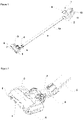
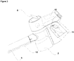
- the present invention relates to a stick vacuum cleaner (1) comprising; a body (2), a brush head (3) having a bracket (4), a pipe (5) extending between and connecting the body (2) to the brush head (3) via the bracket (4), at least a camera (6) and a light source (7) placed on to the brush head (3) so as to capture the image of the area to be swept, a display (8) placed on to the body (2) to display the image captured by the camera (6).
- the present invention relates to a stick vacuum cleaner (1) comprising; a dust sensor (9) placed near to the brush head (3) to detect the dust particles inside the air sucked through the brush head (3), a control unit (10) configured to; recognize the dust particles on the image, highlight the dust particles on the display (8), remove highlighting if the dust sensor (9) detects the passage of the dust particles simultaneously with the sweeping movement of the brush head (3) of the area where on the dust particles were previously detected.
- the dust sensor (9) is configured to detect the passage of dust particles inside the pipe (5).
- the control unit (10) receives signal from the dust sensor (9) in real time and compares this data with the data acquired by the camera (6).
- the control unit (10) decides that the dust particle is sucked inside the stick vacuum cleaner (1) and removes highlighted area on the display. Therefore, all the dust particles are effectively removed from areas that are hard to access and ease of use is provided for the user.
- an auditory signal means (11) is placed on to the body (2) so as to notify the user of removal of the dust particles. Removal of highlighted area on the display (8) triggers the control unit (10) to send a signal to the auditory signal means (11) which in turn gives an auditory signal to the user. Therefore, the user is notified of the removal of dust and foreign particles.
- the light source (7) is placed in between the two cameras (6).
- the control unit (10) detects the exact location of the dust particles to be swept in an accurate manner.
- the user has to make a minimum number of sweeps on an area where on the dust particles were previously detected.
- the light source (7) is configured to emit light in differentiating wavelengths.
- the dust particles are formed from a wide range of materials having different shapes, colors and reflection values. By continuously changing the wavelength of the light source (7), the dust particles are illuminated in an effective way, therefore improving cleaning capacity of the stick vacuum cleaner (1).
- the camera (6) is removable attachable to the brush head (3). Therefore, damaged cameras (6) are easily replaced, decreasing the maintenance cost of the stick vacuum cleaner (1).
- control unit (10) is in wireless communication with the camera (6), the light source (7) and the dust sensor (9).
- the camera (6), the light source (7) and the dust sensor (9) is connected to a communication hub having wireless communication abilities which is wirelessly connected to the control unit (10).
- cables extending between the brush head (3) and the body (2) are not utilized thereby achieving a cost advantage.
- Another advantageous effect of using wireless connection is that the cables extending between the brush head (3) and the body (2) are prone to get damaged during sweeping. Use of wireless communication eliminates this possibility therefore decreasing the maintenance costs of the stick vacuum cleaner (1).
- control unit (10) is connected to the camera (6), the light source (7) and the dust sensor (9) via a cable (12) extending between the brush head (3) and the body (2).
- a cable (12) extending between the brush head (3) and the body (2) and covered inside a cable duct provides a cost effective way to connect control unit (11) with the camera (6), the light source (7) and the dust sensor (9).
Landscapes
- Engineering & Computer Science (AREA)
- Mechanical Engineering (AREA)
- Electric Vacuum Cleaner (AREA)
Claims (7)
- Ein Stabstaubsauger (1) umfasst einen Körper (2), einen Bürstenkopf (3) mit einer Halterung (4), ein Rohr (5), das sich zwischen dem Körper (2) und dem Bürstenkopf (3) über die Halterung (4) erstreckt und diese miteinander verbindet, mindestens eine Kamera (6) und eine Lichtquelle (7), die auf dem Bürstenkopf (3) angeordnet sind, um das Bild der zu kehrenden Fläche zu erfassen, ein Display (8), das auf dem Körper (2) angeordnet ist, um das von der Kamera (6) aufgenommene Bild anzuzeigen, gekennzeichnet ist er durch einen nahe dem Bürstenkopf (3) angeordneten Staubsensor (9) zum Erfassen der Staubpartikel innerhalb der durch den Bürstenkopf (3) gesaugten Luft, wobei eine Steuereinheit (10), die dazu konfiguriert ist;• die Staubpartikeln auf dem Bild zu erkennen,• die Staubpartikel auf dem Display (8) hervorzuheben,• Hervorhebungen zu entfernen, wenn der Staubsensor (9) gleichzeitig mit der Wischbewegung des Bürstenkopfes (3) den Durchgang der Staubpartikel in dem Bereich erfasst, in dem zuvor Staubpartikel erfasst wurden.
- Ein Stabstaubsauger (1), wie in Anspruch 1 aufgeführt, ist dadurch gekennzeichnet, dass ein hörbares Signalmittel (11) auf dem Körper (2) angeordnet ist, um den Benutzer über das Entfernen der Staubpartikel zu informieren.
- Ein Stabstaubsauger (1), wie in den vorherigen Ansprüchen aufgeführt, ist dadurch gekennzeichnet, dass die Lichtquelle (7) zwischen den beiden Kameras (6) angeordnet ist.
- Ein Stabstaubsauger (1), wie in den vorherigen Ansprüchen aufgeführt, ist dadurch gekennzeichnet, dass die Lichtquelle (7) dazu konfiguriert ist, Licht in differenzierenden Wellenlängen zu emittieren.
- Ein Stabstaubsauger (1), wie in den vorherigen Ansprüchen aufgeführt, ist dadurch gekennzeichnet, dass die Kamera (6) abnehmbar am Bürstenkopf (3) zu befestigen ist.
- Ein Stabstaubsauger (1), wie in den vorherigen Ansprüchen aufgeführt, ist dadurch gekennzeichnet, die Steuereinheit (10) in drahtloser Kommunikation mit der Kamera (10), der Lichtquelle (7) und dem Staubsensor (9) steht.
- Ein Stabstaubsauger (1), wie in den Ansprüchen 1 bis 5 aufgeführt, ist dadurch gekennzeichnet, dass die Steuereinheit (10) mit der Kamera (6), der Lichtquelle (7) und dem Staubsensor (9) über ein Kabel (12) verbunden ist, dass sich zwischen dem Bürstenkopf (3) und dem Körper (2) erstreckt.
Applications Claiming Priority (2)
| Application Number | Priority Date | Filing Date | Title |
|---|---|---|---|
| TR201809060 | 2018-06-27 | ||
| PCT/EP2019/063999 WO2020001912A1 (en) | 2018-06-27 | 2019-05-29 | A stick vacuum cleaner |
Publications (2)
| Publication Number | Publication Date |
|---|---|
| EP3813621A1 EP3813621A1 (de) | 2021-05-05 |
| EP3813621B1 true EP3813621B1 (de) | 2022-05-04 |
Family
ID=66677156
Family Applications (1)
| Application Number | Title | Priority Date | Filing Date |
|---|---|---|---|
| EP19727664.5A Active EP3813621B1 (de) | 2018-06-27 | 2019-05-29 | Ein stabstaubsauger |
Country Status (2)
| Country | Link |
|---|---|
| EP (1) | EP3813621B1 (de) |
| WO (1) | WO2020001912A1 (de) |
Families Citing this family (1)
| Publication number | Priority date | Publication date | Assignee | Title |
|---|---|---|---|---|
| CN114158982A (zh) * | 2021-12-07 | 2022-03-11 | 添可智能科技有限公司 | 清洁方法和清洁设备 |
Family Cites Families (4)
| Publication number | Priority date | Publication date | Assignee | Title |
|---|---|---|---|---|
| JP2006141836A (ja) * | 2004-11-24 | 2006-06-08 | Fuji Photo Film Co Ltd | 電気掃除機 |
| CN201641896U (zh) | 2010-04-13 | 2010-11-24 | 瞿屹君 | 带摄像头和液晶屏的扫把 |
| WO2014196272A1 (ja) * | 2013-06-03 | 2014-12-11 | Sako Yoichiro | 電気掃除装置 |
| JP2018088970A (ja) * | 2016-11-30 | 2018-06-14 | 東芝ライフスタイル株式会社 | 電気掃除機 |
-
2019
- 2019-05-29 EP EP19727664.5A patent/EP3813621B1/de active Active
- 2019-05-29 WO PCT/EP2019/063999 patent/WO2020001912A1/en not_active Ceased
Also Published As
| Publication number | Publication date |
|---|---|
| WO2020001912A1 (en) | 2020-01-02 |
| EP3813621A1 (de) | 2021-05-05 |
Similar Documents
| Publication | Publication Date | Title |
|---|---|---|
| US11039723B2 (en) | Surface cleaning apparatus | |
| US9833116B2 (en) | Method and apparatus for providing multiple modes of cleaning on a smart robotic cleaner | |
| EP2941994B1 (de) | Staubsauger | |
| KR101484942B1 (ko) | 청소기 및 그 제어방법 | |
| CN109890258A (zh) | 具有抽吸的多模式清洁设备 | |
| CN107788913A (zh) | 清洁机器人及其控制方法 | |
| EP2457486A3 (de) | Reinigungsroboter und Steuerungsverfahren dafür | |
| JP2013233305A (ja) | 自走式掃除機 | |
| WO2018152843A1 (en) | Handheld vacuum cleaner | |
| KR20160031836A (ko) | 진공청소기, 그의 제어방법 및 컴퓨터 판독가능 기록매체 | |
| TW201444517A (zh) | 自走式清潔裝置及其吸塵方法 | |
| EP3585231A1 (de) | Handstaubsauger | |
| CN108742355B (zh) | 一种室内地面智能清洁机器人 | |
| WO2020001912A1 (en) | A stick vacuum cleaner | |
| CN102462452B (zh) | 电动吸尘器 | |
| JP2004529681A (ja) | 真空掃除機用清掃ヘッド | |
| EP2263509A3 (de) | Industrie- und Haushaltsreinigungsmaschine | |
| EP3809936B1 (de) | Ein stabsauger | |
| KR20200030014A (ko) | 청소된 영역이 구분 가능한 청소기 | |
| CN117281427A (zh) | 清洁设备 | |
| CN205758456U (zh) | 一种扫地机器人灰尘盒 | |
| JP2006187477A5 (de) | ||
| KR20120116248A (ko) | 로봇 청소기 | |
| US10980381B1 (en) | Nozzle assembly for vacuum device | |
| GB2101472A (en) | A vacuum cleaning unit |
Legal Events
| Date | Code | Title | Description |
|---|---|---|---|
| STAA | Information on the status of an ep patent application or granted ep patent |
Free format text: STATUS: UNKNOWN |
|
| STAA | Information on the status of an ep patent application or granted ep patent |
Free format text: STATUS: THE INTERNATIONAL PUBLICATION HAS BEEN MADE |
|
| PUAI | Public reference made under article 153(3) epc to a published international application that has entered the european phase |
Free format text: ORIGINAL CODE: 0009012 |
|
| STAA | Information on the status of an ep patent application or granted ep patent |
Free format text: STATUS: REQUEST FOR EXAMINATION WAS MADE |
|
| 17P | Request for examination filed |
Effective date: 20201222 |
|
| AK | Designated contracting states |
Kind code of ref document: A1 Designated state(s): AL AT BE BG CH CY CZ DE DK EE ES FI FR GB GR HR HU IE IS IT LI LT LU LV MC MK MT NL NO PL PT RO RS SE SI SK SM TR |
|
| DAV | Request for validation of the european patent (deleted) | ||
| DAX | Request for extension of the european patent (deleted) | ||
| GRAP | Despatch of communication of intention to grant a patent |
Free format text: ORIGINAL CODE: EPIDOSNIGR1 |
|
| STAA | Information on the status of an ep patent application or granted ep patent |
Free format text: STATUS: GRANT OF PATENT IS INTENDED |
|
| INTG | Intention to grant announced |
Effective date: 20220203 |
|
| GRAS | Grant fee paid |
Free format text: ORIGINAL CODE: EPIDOSNIGR3 |
|
| GRAA | (expected) grant |
Free format text: ORIGINAL CODE: 0009210 |
|
| STAA | Information on the status of an ep patent application or granted ep patent |
Free format text: STATUS: THE PATENT HAS BEEN GRANTED |
|
| AK | Designated contracting states |
Kind code of ref document: B1 Designated state(s): AL AT BE BG CH CY CZ DE DK EE ES FI FR GB GR HR HU IE IS IT LI LT LU LV MC MK MT NL NO PL PT RO RS SE SI SK SM TR |
|
| REG | Reference to a national code |
Ref country code: GB Ref legal event code: FG4D |
|
| REG | Reference to a national code |
Ref country code: CH Ref legal event code: EP |
|
| REG | Reference to a national code |
Ref country code: AT Ref legal event code: REF Ref document number: 1488125 Country of ref document: AT Kind code of ref document: T Effective date: 20220515 |
|
| REG | Reference to a national code |
Ref country code: DE Ref legal event code: R096 Ref document number: 602019014575 Country of ref document: DE |
|
| REG | Reference to a national code |
Ref country code: IE Ref legal event code: FG4D |
|
| REG | Reference to a national code |
Ref country code: LT Ref legal event code: MG9D |
|
| REG | Reference to a national code |
Ref country code: NL Ref legal event code: MP Effective date: 20220504 |
|
| REG | Reference to a national code |
Ref country code: AT Ref legal event code: MK05 Ref document number: 1488125 Country of ref document: AT Kind code of ref document: T Effective date: 20220504 |
|
| PG25 | Lapsed in a contracting state [announced via postgrant information from national office to epo] |
Ref country code: SE Free format text: LAPSE BECAUSE OF FAILURE TO SUBMIT A TRANSLATION OF THE DESCRIPTION OR TO PAY THE FEE WITHIN THE PRESCRIBED TIME-LIMIT Effective date: 20220504 Ref country code: PT Free format text: LAPSE BECAUSE OF FAILURE TO SUBMIT A TRANSLATION OF THE DESCRIPTION OR TO PAY THE FEE WITHIN THE PRESCRIBED TIME-LIMIT Effective date: 20220905 Ref country code: NO Free format text: LAPSE BECAUSE OF FAILURE TO SUBMIT A TRANSLATION OF THE DESCRIPTION OR TO PAY THE FEE WITHIN THE PRESCRIBED TIME-LIMIT Effective date: 20220804 Ref country code: NL Free format text: LAPSE BECAUSE OF FAILURE TO SUBMIT A TRANSLATION OF THE DESCRIPTION OR TO PAY THE FEE WITHIN THE PRESCRIBED TIME-LIMIT Effective date: 20220504 Ref country code: LT Free format text: LAPSE BECAUSE OF FAILURE TO SUBMIT A TRANSLATION OF THE DESCRIPTION OR TO PAY THE FEE WITHIN THE PRESCRIBED TIME-LIMIT Effective date: 20220504 Ref country code: HR Free format text: LAPSE BECAUSE OF FAILURE TO SUBMIT A TRANSLATION OF THE DESCRIPTION OR TO PAY THE FEE WITHIN THE PRESCRIBED TIME-LIMIT Effective date: 20220504 Ref country code: GR Free format text: LAPSE BECAUSE OF FAILURE TO SUBMIT A TRANSLATION OF THE DESCRIPTION OR TO PAY THE FEE WITHIN THE PRESCRIBED TIME-LIMIT Effective date: 20220805 Ref country code: FI Free format text: LAPSE BECAUSE OF FAILURE TO SUBMIT A TRANSLATION OF THE DESCRIPTION OR TO PAY THE FEE WITHIN THE PRESCRIBED TIME-LIMIT Effective date: 20220504 Ref country code: BG Free format text: LAPSE BECAUSE OF FAILURE TO SUBMIT A TRANSLATION OF THE DESCRIPTION OR TO PAY THE FEE WITHIN THE PRESCRIBED TIME-LIMIT Effective date: 20220804 Ref country code: AT Free format text: LAPSE BECAUSE OF FAILURE TO SUBMIT A TRANSLATION OF THE DESCRIPTION OR TO PAY THE FEE WITHIN THE PRESCRIBED TIME-LIMIT Effective date: 20220504 |
|
| PG25 | Lapsed in a contracting state [announced via postgrant information from national office to epo] |
Ref country code: RS Free format text: LAPSE BECAUSE OF FAILURE TO SUBMIT A TRANSLATION OF THE DESCRIPTION OR TO PAY THE FEE WITHIN THE PRESCRIBED TIME-LIMIT Effective date: 20220504 Ref country code: PL Free format text: LAPSE BECAUSE OF FAILURE TO SUBMIT A TRANSLATION OF THE DESCRIPTION OR TO PAY THE FEE WITHIN THE PRESCRIBED TIME-LIMIT Effective date: 20220504 Ref country code: LV Free format text: LAPSE BECAUSE OF FAILURE TO SUBMIT A TRANSLATION OF THE DESCRIPTION OR TO PAY THE FEE WITHIN THE PRESCRIBED TIME-LIMIT Effective date: 20220504 Ref country code: IS Free format text: LAPSE BECAUSE OF FAILURE TO SUBMIT A TRANSLATION OF THE DESCRIPTION OR TO PAY THE FEE WITHIN THE PRESCRIBED TIME-LIMIT Effective date: 20220904 |
|
| REG | Reference to a national code |
Ref country code: CH Ref legal event code: PL |
|
| REG | Reference to a national code |
Ref country code: BE Ref legal event code: MM Effective date: 20220531 |
|
| PG25 | Lapsed in a contracting state [announced via postgrant information from national office to epo] |
Ref country code: SM Free format text: LAPSE BECAUSE OF FAILURE TO SUBMIT A TRANSLATION OF THE DESCRIPTION OR TO PAY THE FEE WITHIN THE PRESCRIBED TIME-LIMIT Effective date: 20220504 Ref country code: SK Free format text: LAPSE BECAUSE OF FAILURE TO SUBMIT A TRANSLATION OF THE DESCRIPTION OR TO PAY THE FEE WITHIN THE PRESCRIBED TIME-LIMIT Effective date: 20220504 Ref country code: RO Free format text: LAPSE BECAUSE OF FAILURE TO SUBMIT A TRANSLATION OF THE DESCRIPTION OR TO PAY THE FEE WITHIN THE PRESCRIBED TIME-LIMIT Effective date: 20220504 Ref country code: LU Free format text: LAPSE BECAUSE OF NON-PAYMENT OF DUE FEES Effective date: 20220529 Ref country code: LI Free format text: LAPSE BECAUSE OF NON-PAYMENT OF DUE FEES Effective date: 20220531 Ref country code: ES Free format text: LAPSE BECAUSE OF FAILURE TO SUBMIT A TRANSLATION OF THE DESCRIPTION OR TO PAY THE FEE WITHIN THE PRESCRIBED TIME-LIMIT Effective date: 20220504 Ref country code: EE Free format text: LAPSE BECAUSE OF FAILURE TO SUBMIT A TRANSLATION OF THE DESCRIPTION OR TO PAY THE FEE WITHIN THE PRESCRIBED TIME-LIMIT Effective date: 20220504 Ref country code: DK Free format text: LAPSE BECAUSE OF FAILURE TO SUBMIT A TRANSLATION OF THE DESCRIPTION OR TO PAY THE FEE WITHIN THE PRESCRIBED TIME-LIMIT Effective date: 20220504 Ref country code: CZ Free format text: LAPSE BECAUSE OF FAILURE TO SUBMIT A TRANSLATION OF THE DESCRIPTION OR TO PAY THE FEE WITHIN THE PRESCRIBED TIME-LIMIT Effective date: 20220504 Ref country code: CH Free format text: LAPSE BECAUSE OF NON-PAYMENT OF DUE FEES Effective date: 20220531 |
|
| REG | Reference to a national code |
Ref country code: DE Ref legal event code: R097 Ref document number: 602019014575 Country of ref document: DE |
|
| PG25 | Lapsed in a contracting state [announced via postgrant information from national office to epo] |
Ref country code: MC Free format text: LAPSE BECAUSE OF FAILURE TO SUBMIT A TRANSLATION OF THE DESCRIPTION OR TO PAY THE FEE WITHIN THE PRESCRIBED TIME-LIMIT Effective date: 20220504 |
|
| PLBE | No opposition filed within time limit |
Free format text: ORIGINAL CODE: 0009261 |
|
| STAA | Information on the status of an ep patent application or granted ep patent |
Free format text: STATUS: NO OPPOSITION FILED WITHIN TIME LIMIT |
|
| PG25 | Lapsed in a contracting state [announced via postgrant information from national office to epo] |
Ref country code: AL Free format text: LAPSE BECAUSE OF FAILURE TO SUBMIT A TRANSLATION OF THE DESCRIPTION OR TO PAY THE FEE WITHIN THE PRESCRIBED TIME-LIMIT Effective date: 20220504 |
|
| 26N | No opposition filed |
Effective date: 20230207 |
|
| PG25 | Lapsed in a contracting state [announced via postgrant information from national office to epo] |
Ref country code: IE Free format text: LAPSE BECAUSE OF NON-PAYMENT OF DUE FEES Effective date: 20220529 |
|
| PG25 | Lapsed in a contracting state [announced via postgrant information from national office to epo] |
Ref country code: SI Free format text: LAPSE BECAUSE OF FAILURE TO SUBMIT A TRANSLATION OF THE DESCRIPTION OR TO PAY THE FEE WITHIN THE PRESCRIBED TIME-LIMIT Effective date: 20220504 Ref country code: BE Free format text: LAPSE BECAUSE OF NON-PAYMENT OF DUE FEES Effective date: 20220531 |
|
| PG25 | Lapsed in a contracting state [announced via postgrant information from national office to epo] |
Ref country code: IT Free format text: LAPSE BECAUSE OF FAILURE TO SUBMIT A TRANSLATION OF THE DESCRIPTION OR TO PAY THE FEE WITHIN THE PRESCRIBED TIME-LIMIT Effective date: 20220504 |
|
| PG25 | Lapsed in a contracting state [announced via postgrant information from national office to epo] |
Ref country code: MK Free format text: LAPSE BECAUSE OF FAILURE TO SUBMIT A TRANSLATION OF THE DESCRIPTION OR TO PAY THE FEE WITHIN THE PRESCRIBED TIME-LIMIT Effective date: 20220504 Ref country code: CY Free format text: LAPSE BECAUSE OF FAILURE TO SUBMIT A TRANSLATION OF THE DESCRIPTION OR TO PAY THE FEE WITHIN THE PRESCRIBED TIME-LIMIT Effective date: 20220504 |
|
| PG25 | Lapsed in a contracting state [announced via postgrant information from national office to epo] |
Ref country code: HU Free format text: LAPSE BECAUSE OF FAILURE TO SUBMIT A TRANSLATION OF THE DESCRIPTION OR TO PAY THE FEE WITHIN THE PRESCRIBED TIME-LIMIT; INVALID AB INITIO Effective date: 20190529 |
|
| PG25 | Lapsed in a contracting state [announced via postgrant information from national office to epo] |
Ref country code: MT Free format text: LAPSE BECAUSE OF FAILURE TO SUBMIT A TRANSLATION OF THE DESCRIPTION OR TO PAY THE FEE WITHIN THE PRESCRIBED TIME-LIMIT Effective date: 20220504 |
|
| PG25 | Lapsed in a contracting state [announced via postgrant information from national office to epo] |
Ref country code: BG Free format text: LAPSE BECAUSE OF FAILURE TO SUBMIT A TRANSLATION OF THE DESCRIPTION OR TO PAY THE FEE WITHIN THE PRESCRIBED TIME-LIMIT Effective date: 20220504 |
|
| PG25 | Lapsed in a contracting state [announced via postgrant information from national office to epo] |
Ref country code: BG Free format text: LAPSE BECAUSE OF FAILURE TO SUBMIT A TRANSLATION OF THE DESCRIPTION OR TO PAY THE FEE WITHIN THE PRESCRIBED TIME-LIMIT Effective date: 20220504 |
|
| PGFP | Annual fee paid to national office [announced via postgrant information from national office to epo] |
Ref country code: GB Payment date: 20260306 Year of fee payment: 8 |
|
| PGFP | Annual fee paid to national office [announced via postgrant information from national office to epo] |
Ref country code: DE Payment date: 20260522 Year of fee payment: 8 |
|
| PGFP | Annual fee paid to national office [announced via postgrant information from national office to epo] |
Ref country code: TR Payment date: 20260507 Year of fee payment: 8 |
|
| PGFP | Annual fee paid to national office [announced via postgrant information from national office to epo] |
Ref country code: FR Payment date: 20260526 Year of fee payment: 8 |