EP3812684A1 - Planare wärmeübertragungsvorrichtung und verfahren zu deren herstellung - Google Patents
Planare wärmeübertragungsvorrichtung und verfahren zu deren herstellung Download PDFInfo
- Publication number
- EP3812684A1 EP3812684A1 EP19205010.2A EP19205010A EP3812684A1 EP 3812684 A1 EP3812684 A1 EP 3812684A1 EP 19205010 A EP19205010 A EP 19205010A EP 3812684 A1 EP3812684 A1 EP 3812684A1
- Authority
- EP
- European Patent Office
- Prior art keywords
- wall
- working fluid
- capillary
- support structure
- transfer device
- Prior art date
- Legal status (The legal status is an assumption and is not a legal conclusion. Google has not performed a legal analysis and makes no representation as to the accuracy of the status listed.)
- Granted
Links
Images




Classifications
-
- F—MECHANICAL ENGINEERING; LIGHTING; HEATING; WEAPONS; BLASTING
- F28—HEAT EXCHANGE IN GENERAL
- F28D—HEAT-EXCHANGE APPARATUS, NOT PROVIDED FOR IN ANOTHER SUBCLASS, IN WHICH THE HEAT-EXCHANGE MEDIA DO NOT COME INTO DIRECT CONTACT
- F28D15/00—Heat-exchange apparatus with the intermediate heat-transfer medium in closed tubes passing into or through the conduit walls ; Heat-exchange apparatus employing intermediate heat-transfer medium or bodies
- F28D15/02—Heat-exchange apparatus with the intermediate heat-transfer medium in closed tubes passing into or through the conduit walls ; Heat-exchange apparatus employing intermediate heat-transfer medium or bodies in which the medium condenses and evaporates, e.g. heat pipes
- F28D15/0233—Heat-exchange apparatus with the intermediate heat-transfer medium in closed tubes passing into or through the conduit walls ; Heat-exchange apparatus employing intermediate heat-transfer medium or bodies in which the medium condenses and evaporates, e.g. heat pipes the conduits having a particular shape, e.g. non-circular cross-section, annular
-
- F—MECHANICAL ENGINEERING; LIGHTING; HEATING; WEAPONS; BLASTING
- F28—HEAT EXCHANGE IN GENERAL
- F28D—HEAT-EXCHANGE APPARATUS, NOT PROVIDED FOR IN ANOTHER SUBCLASS, IN WHICH THE HEAT-EXCHANGE MEDIA DO NOT COME INTO DIRECT CONTACT
- F28D15/00—Heat-exchange apparatus with the intermediate heat-transfer medium in closed tubes passing into or through the conduit walls ; Heat-exchange apparatus employing intermediate heat-transfer medium or bodies
- F28D15/02—Heat-exchange apparatus with the intermediate heat-transfer medium in closed tubes passing into or through the conduit walls ; Heat-exchange apparatus employing intermediate heat-transfer medium or bodies in which the medium condenses and evaporates, e.g. heat pipes
- F28D15/04—Heat-exchange apparatus with the intermediate heat-transfer medium in closed tubes passing into or through the conduit walls ; Heat-exchange apparatus employing intermediate heat-transfer medium or bodies in which the medium condenses and evaporates, e.g. heat pipes with tubes having a capillary structure
- F28D15/046—Heat-exchange apparatus with the intermediate heat-transfer medium in closed tubes passing into or through the conduit walls ; Heat-exchange apparatus employing intermediate heat-transfer medium or bodies in which the medium condenses and evaporates, e.g. heat pipes with tubes having a capillary structure characterised by the material or the construction of the capillary structure
-
- F—MECHANICAL ENGINEERING; LIGHTING; HEATING; WEAPONS; BLASTING
- F28—HEAT EXCHANGE IN GENERAL
- F28F—DETAILS OF HEAT-EXCHANGE AND HEAT-TRANSFER APPARATUS, OF GENERAL APPLICATION
- F28F2225/00—Reinforcing means
- F28F2225/04—Reinforcing means for conduits
Definitions
- the present invention relates to a planar heat transfer device and a method for its production and in particular to large-area planar heat exchangers (flat design of the heat pipes, so-called heat pipes) with a folded capillary structure.
- Planar heat pipes are heat transfer devices that provide an efficient heat balance or a possibility for planar heat transfer in a surface. In doing so, due to their isothermal design, they compensate for temperature peaks and ensure an even temperature distribution. At the same time, very large heat flows can be transferred, for example to a heat sink in an edge area.
- Planar heat pipes are already often used today for the surface cooling of electronic components. These are usually made by sintering layers in layers and are only a few cm 2 in size.
- a support structure is introduced into the heat pipes in order to be able to absorb the pressure forces.
- a planar heat pipe usually comprises two metal sheets (or walls in general) that are sealed tightly at a certain distance from one another. In the cavity created in this way, there is a working fluid which permanently condenses and evaporates during operation. This phase transition makes it possible to transfer large amounts of heat at a constant temperature level.
- the support structures used are, for example, knobs which must also be introduced.
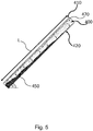
- Fig. 5 Fig. 10 shows an example of such a conventional planar heat transfer device having a first wall 410 and an opposing second wall 420.
- the first wall 410 and the second wall 420 extend, for example, in parallel in a surface (plane) in a predetermined one Distance from each other and have a length L.
- a working fluid 450 is introduced into the cavity 400 thus formed, which in the liquid phase collects vertically at the bottom and fills the cavity 400 in the gas phase above.
- a capillary structure 470 is formed along the first wall 410, which leads to the fact that liquid working fluid 450 is carried vertically upwards by the capillary action.
- the liquid working fluid 450 gradually evaporates along the first wall 410 (by a heat source acting there).
- the gaseous working fluid condenses and flows vertically downwards in the liquid phase.
- the entire cavity 400 thus forms a heat circuit for the working fluid.
- the working fluid condensing on the second (condenser) side 420 runs through gravity to the lowest point of the heat pipe. From there it must now be pumped along the evaporation surfaces with the help of capillary forces. Correct operation of the heat pipe can only be guaranteed if the entire surface of the evaporator is supplied with working fluid. The required height of rise is therefore dependent on the length L of the heat pipe and its angle of inclination ⁇ . The capillary effect can only be implemented over a limited amount. In order to achieve complete wetting of the first wall, the liquid working fluid would have to be at a total height L. ⁇ sin ⁇ be transported, where ⁇ is the angle of inclination of the conventional heat transfer device relative to the horizontal.
- the rigidity of the construction also limits the maximum dimensions.
- the distance between the metal sheets 410, 420 must be kept more or less constant over the entire surface, since the vapor space should not be impaired by a sagging of the metal sheets.
- the present invention relates to a planar heat transfer device for distributing and removing heat from a planar heat source.
- the device includes: a lumen and a capillary support structure.
- the cavity is delimited by a first wall for coupling to the planar heat source and an opposing second wall and includes a working fluid (e.g., a phase change material).
- the capillary support structure extends folded in at least one direction between the first wall and the second wall to provide support and capillary action for condensed working fluid. This enables condensed working fluid to be transported through the capillary support structure from the second wall to the first wall.
- the capillary support structure thus fulfills two functions: the provision of a capillary effect for the transport of condensed working fluid and the support of the first against the second wall.
- the walls can in particular be planar or flat and extend, for example, in the form of a plate in one plane.
- the folded capillary support structure forms, for example, a wave-shaped cross section along the folding direction.
- the capillary support structure can be formed, for example, from a wire mesh, which on the one hand offers sufficient mechanical stability and on the other hand provides pore structures for capillary transport. It can be advantageous if the first and the second wall provide a certain prestress in order to compress the capillary support structure in order to keep the pore structure in the wire mesh correspondingly small and to increase the capillary action.
- the material of the capillary support structure can be selected in such a way (e.g. from a metal) that no additional spacers are required.
- the capillary support structure can completely fill the cavity so that it cannot be pushed away to the side by the acting force.
- cavity should not be restricted to the fact that there is a vacuum in this space. Rather, there will be at least the working fluid in the liquid or gaseous phase or a mixture of the two. In addition, substances can also be present (e.g. air).
- the capillary support structure is formed around the first wall and the to keep the second wall parallel to each other at a predetermined distance.
- This negative pressure creates a force that has to support the capillary support structure.
- the geometry of the vapor space can be kept optimal and the desired heat transfer can take place efficiently. Therefore, the heat transfer device can optionally have one or more additional spacers in order to ensure the predetermined distance.
- the capillary support structure can thus be formed in such a way that it provides sufficient support.
- it is advantageously formed with sufficient strength and also folded in such a way that the desired mechanical stability is achieved.
- the sections that extend between the first and the second wall can be designed obliquely or almost perpendicularly to the first and the second wall.
- triangular cavities can be formed (in a cross section along the fold) in order to achieve the desired mechanical stability.
- the cavity is sealed in a vacuum-tight manner in order to form a vapor space for the working fluid (in the liquid and / or gaseous phase), the vapor space being subdivided by folding the capillary support structure.
- the capillary support structure thus forms a multiplicity of partition walls in the cavity through the folds.
- the capillary support structure is folded in at least one direction, so that in the direction perpendicular thereto, the capillary support structure represents a line-shaped pattern. The lines are formed by the folds.
- the pressure in the cavity can also be adjusted accordingly in order to set a phase transition temperature accordingly.
- This adaptation depends, for example, on the area of application (e.g. whether it is used for photovoltaic systems, for building cooling, for cooling electronic components, etc.).
- the distance between adjacent folds can be selected such that it has approximately the same value as the predetermined distance between the first wall and the second wall.
- the capillary support structure has openings in order to achieve a permeability of the capillary support structure for the gaseous working fluid.
- These openings can be present in addition to the existing capillary-acting pores (or openings in the braid) and can be made larger so that they are not clogged by liquid working fluid.
- working fluid in the gas phase can spread throughout the entire cavity and thus effect an efficient heat balance. In particular, it can easily flow vertically upwards (against gravity) and thermally connect several spaces between the folds.
- the capillary support structure is designed as a homogeneous structure (e.g. as a homogeneous grid or wire mesh).
- the capillary support structure extends at least partially parallel along the second wall in order to transport condensed working fluid against gravity along the second wall, the first wall forming an evaporation surface and the second wall forming a condensation surface for the working fluid.
- a further capillary structure can be formed along the second wall in order to enable a transport of condensed working fluid against gravity from one fold interspace to an adjacent fold interspace along the second wall.
- a continuous further capillary structure offers the advantage that the working fluid in the liquid phase can be transported upwards, specifically along the second wall, where the liquid phase of the working fluid condenses.
- the sections formed parallel to the second wall have the same effect.
- the heat transfer device comprises (at least) a heat sink in an edge region of the cavity, the edge region for example lies in the direction of folding (perpendicular to the direction of the fold).
- the heat sink can, for example, allow cooling via water or air (via a fan or cooling fins).
- the introduction of the working fluid is independent of the manufacture of the cavity between the first and second walls and the folded capillary support structure arranged therein.
- the working fluid can later, depending on the application, be introduced via an existing opening (for example, the air can escape via a further opening).
- the air can optionally be evacuated beforehand.
- the working fluid can also be introduced first and the air present is later removed from the cavity.
- the cavity it is also possible for the cavity to be completely filled with working fluid in the gaseous phase, for example in the gas phase at a correspondingly high temperature, so that the air located therein is automatically displaced.
- this introduction of the gaseous working fluid can take place in such a way that the opening is vertically above the cavity or below it, whereby an effective introduction becomes possible.
- the heat transfer device can be cooled, which leads to condensation of the working fluid, so that the heat transfer device that then results can be used.
- Fig. 1 shows a planar heat transfer device suitable for heat distribution and removal of heat from a planar heat source.
- the heat transfer device includes a cavity 100 delimited by a first wall 110 for coupling to the planar heat source and an opposing second wall 120.
- the device further comprises a capillary support structure 200 having folds 210 in at least one direction R (or opposite thereto) extending between the first wall 110 and the second wall 120 to provide support and capillary action for condensed working fluid.
- the working fluid has not yet been introduced into the cavity 100.
- the capillary support structure 200 is formed folded in the cavity 100. It can extend in sections along the second wall 120 and is periodically (wave-shaped) folded towards the first wall 110. No edges or corners need be formed. The rounded folds shown facilitate the transport of liquids. According to exemplary embodiments, there are no fastenings on the first and second walls 110, 120 (the walls 110, 120 are only supported), but can optionally be present.
- the first wall 110 and / or the second wall 120 can be designed as metal sheets to provide a to achieve thermal coupling to the environment.
- the capillary support structure 200 can be designed as a homogeneous structure along the folds 210. In particular, no further openings are required, but can be designed optionally.
- the folds 210 enclose triangular areas, for example, which ensure high mechanical stability. This is advantageous since there are generally no further spacers.
- the capillary support structure 200 in particular has sufficient mechanical stability to keep the first and the second wall at a predetermined distance t from one another, even when the cavity 100 is evacuated and / or thermal stresses / negative pressure exert a force perpendicular to the first and second wall 110,120.
- the capillary support structure 200 is formed, for example, in the form of a wire mesh (e.g. made of metal) and not as a continuous metal foil or sheet metal. In order to achieve a sufficient support effect, the capillary support structure 200 can extend over the entire cavity 100 and abut the ends of the cavity 100. The capillary support structure 200 can then not be pushed out laterally.
- a wire mesh e.g. made of metal
- Fig. 2 shows a planar heat transfer device according to a further embodiment, which is designed for heat distribution and for the removal of heat from a planar heat source 50.
- the working fluid 150 is introduced into the cavity 100.
- the planar heat source 50 is only shown schematically via the generated heat Q, which leads to a heat input into the first wall 110, as a result of which the working fluid 150 at least partially evaporates.
- This first wall 110 thus acts as an evaporation wall.
- the second wall 120 on which the working fluid 150 at least partially condenses, is formed in the heat transfer device opposite the first wall 110.
- This second wall 120 thus acts as a condensation wall.
- the working fluid 150 changes its physical state continuously from liquid to vapor or gaseous.
- the exemplary embodiments thus overcome the three problems of conventional planar heat pipes.
- the introduced wire mesh 200 provides the capillarity and the folds 210 (or beads) formed provide the support function, since they absorb the axial forces between the two walls 110, 120. This not only increases the rigidity, but at the same time ensures that the required distance t between the walls 110, 120 (vapor space) is maintained.
- the additional support structure previously required can be omitted.
- the capillary structure which is required for the capillary action, takes on this task and thus replaces an additional component.
- the folded capillary structure 200 it is possible to build very large planar heat pipes.
- the folds 210 divide the cavity 100 into separate areas in which the working fluid 150 circulates.
- H t - t mesh ⁇ cos ⁇
- t the predetermined distance between the first and second walls 110, 120
- t mesh is the thickness of the capillary support structure 200 (eg the braid)
- ⁇ is the angle of inclination.
- FIGS 3A, 3B show enlarged representations of the heat transfer device according to exemplary embodiments, wherein in FIG Figure 3A to see an exemplary inclined application and in the Figure 3B a horizontal application example is shown.
- the first wall 110 is again shown vertically above the second wall 120, between which the folded capillary support structure 200 extends.
- the folds 210 of the capillary support structure 200 thus form partition walls between adjacent vapor spaces 155, 156 for the working fluid 150 and connect the first wall 110 to the second wall 120.
- the connection represents at least one thermal connection that is ensured by the transport of the working fluid 150. No further mechanical connection or coupling needs to exist - but it can be present as an option.
- the first wall 110 is again, by way of example, the wall that couples to the heat source 50 (not shown) and there forms an evaporation surface for the working fluid 150.
- the second wall 120 again represents, for example, a condensation surface in the vicinity of which the working fluid 150 condenses.
- the working fluid 150 is thus in the liquid phase 151 and in the gas phase 152, the liquid working fluid 151 being transported via the capillary action of the capillary support structure 200 on the one hand parallel to the second wall 120 and on the other hand in the direction of the first wall 110.
- the first wall 110 In the vicinity of the first wall 110, the first wall 110 is wetted by the liquid working fluid 151. Since the heat is introduced there via the heat source, the working fluid 150 changes there into the gaseous phase 152, which is then within the respective vapor space section 155 spreads. Condensation again occurs on the second wall 120 and the process is continued, so that a heat cycle 160 is present within each vapor space section 155, 156.
- the first wall 110 can be wetted in both directions, so that a vertical or horizontal heat transport is also achieved. Likewise, in general not all pores of the capillary support structure 200 will be filled with liquid working fluid 151. The capillary support structure 200 will thus still be permeable to the gas phase 152 of the working fluid 150. In this way, too, vertical heat transport can take place.
- the capillary support structure 200 should not only provide a capillary effect for the liquid working fluid 151, but should also have a sufficient support function in order to provide the predetermined distance t between the first surface 110 and the second surface 120.
- the capillary support structure 200 is advantageously folded in such a way that triangular sections 240 are formed which ensure sufficient mechanical stability so that the first wall 120 cannot come into direct contact with the second wall 120.
- the heat should not only be distributed horizontally along the planar surface, but should also be dissipated as possible upwards, against gravity.
- the heat transport against gravity can take place, for example, via the capillary action of the capillary support structure 200 or a further capillary support structure parallel to the second wall 120.
- this vertical heat transport can also take place through the gas phase 152 of the working fluid 150 via openings in the capillary support structure 200.
- the heat transfer device has a homogeneous and isotropic heat distribution along the planar surface, since local overheating leads to heat equalization with the neighboring regions.
- the pressure can be selected, for example, in order to set the evaporation or condensation temperature of the working fluid 150, so that the most efficient possible heat transport can be ensured for the respective application. Because of the lower pressure, there is a force effect of the first wall 110 in the direction of the opposite second wall 120. This pressure results in the folded capillary support structure 200 having to support a vertically acting force. This can have the positive side effect that the pores present in the capillary support structure 200 are correspondingly reduced in size and the capillary effect is thus further increased.
- the capillary support structure 200 can be formed from a stable wire mesh, the wire thickness being selected such that a sufficient support function is achieved for the respective application.
- the wire mesh 200 can be formed homogeneously (translationally symmetrical) and isotropic (rotationally symmetrical, at least with 90 ° rotations). It does not need to have any further, additional openings or additional surface structures.
- the predetermined distance t between two adjacent folds 210 can in principle be selected arbitrarily, but generally represents a compromise between the most complete possible wetting of the first wall 110 and at the same time an effective heat cycle 160 through the working fluid 150 210, at which the capillary support structure 200 comes into contact with the first wall 110 or in the vicinity thereof, are very far, this wetting can be interrupted, so that local overheating can occur. It is therefore advantageous that the spacing of the folds 210 is not made too large. On the other hand, if the distance between If the folds are formed too small, the heat cycle 160 of condensed working fluid 151 and evaporated working fluid 152 (in the gas phase) is not effective. The vapor space 155, 156 is then too small to ensure efficient circulation 160 of the working fluid 150 from the liquid phase 151 to the vapor phase 152 and back to the liquid phase 151.
- a heat sink (not shown) can be formed, for example, at any desired end point in direction R of the folded structure.
- the heat circuit 160 within the individual vapor spaces 155, 156 between the adjacent folds 210 ensures that a uniform, homogeneous temperature profile prevails along the planar expansion of the heat transfer device, so that the cooling can take place at any location.
- the heat sink can, for example, comprise a water bath or air cooling.
Landscapes
- Engineering & Computer Science (AREA)
- Life Sciences & Earth Sciences (AREA)
- Sustainable Development (AREA)
- Physics & Mathematics (AREA)
- Thermal Sciences (AREA)
- Mechanical Engineering (AREA)
- General Engineering & Computer Science (AREA)
- Cooling Or The Like Of Semiconductors Or Solid State Devices (AREA)
Abstract
Description
- Die vorliegende Erfindung bezieht sich auf eine planare Wärmeübertragungsvorrichtung und ein Verfahren zu deren Herstellung und insbesondere auf großflächige planare Wärmübertrager (flächenförmige Ausgestaltung der Wärmerohre, sogenannte Heatpipes) mit gefalteter Kapillarstruktur.
- Planare Heatpipes sind Wärmeübertragungsvorrichtungen, die in einer Fläche einen effizienten Wärmeausgleich bzw. eine Möglichkeit zur flächigen Wärmeübertragung bereitstellen. Dabei gleichen sie, bedingt durch ihre bauartbedingte Isothermie, Temperaturspitzen aus und sorgen für eine gleichmäßige Temperaturverteilung. Gleichzeitig können damit sehr große Wärmeströme übertragen werden, beispielsweise zu einer Wärmesenke in einem Randbereich.
- Planare Heatpipes werden heute bereits häufig zur flächigen Kühlung von Elektronikbauteilen verwendet. Diese werden in der Regel durch schichtweises Sintern gefertigt und sind nur wenige cm2 groß. In die Heatpipes wird zusätzlich zur obligatorischen Kapillarstruktur eine Stützstruktur eingebracht um die Drucckräfte aufnehmen zu können. Eine planare Heatpipe umfasst in der Regel zwei Bleche (oder allgemein Wände), die in einem gewissen Abstand zueinander dicht verschlossen werden. Im so entstandenen Hohlraum befindet sich ein Arbeitsfluid welches im Betrieb permanent kondensiert und verdampft. Durch diesen Phasenübergang ist es möglich, große Wärmemengen auf einem konstanten Temperaturlevel zu übertragen. Die verwendeten Stützstrukturen sind z.B. Noppen welche zusätzlich eingebracht werden müssen.
-
Fig. 5 zeigt ein Beispiel für eine solche konventionelle planare Wärmeübertragungsvorrichtung mit einer ersten Wand 410 und einer gegenüberliegenden zweiten Wand 420. Die erste Wand 410 und die zweite Wand 420 erstrecken sich beispielsweise parallel in einer Fläche (Ebene) in einem vorbestimmten Abstand voneinander und weisen eine Länge L auf. In dem dadurch gebildeten Hohlraum 400 ist ein Arbeitsfluid 450 eingebracht, welches in der flüssigen Phase sich vertikal unten sammelt und in der darüber liegenden Gasphase den Hohlraum 400 ausfüllt. Entlang der ersten Wand 410 ist eine Kapillarstruktur 470 ausgebildet, die dazu führt, dass flüssiges Arbeitsfluid 450 durch die Kapillarwirkung vertikal nach oben getragen wird. Während des Transportes verdampft sukzessive das flüssige Arbeitsfluid 450 entlang der ersten Wand 410 (durch eine dort einwirkende Wärmequelle). In der Nähe der zweiten Wand 420 kondensiert das gasförmige Arbeitsfluid und fließt in der Flüssigkeitsphase vertikal nach unten. Somit bildet der gesamte Hohlraum 400 einen Wärmekreislauf für das Arbeitsfluid. - Das auf der zweiten (Kondensator-) Seite 420 kondensierende Arbeitsfluid läuft durch die Schwerkraft zum tiefsten Punkt der Heatpipe. Von dort muss dieses nun mit Hilfe der Kapillarkräfte entlang der Verdampfungsflächen gepumpt werden. Nur wenn die gesamte Fläche des Verdampfers mit Arbeitsfluid versorgt wird, ist ein ordentlicher Betrieb der Heatpipe gewährleistet. Die benötigte Steighöhe ist somit abhängig von der Länge L der Heatpipe sowie deren Neigungswinkel α. Die Kapillarwirkung ist nur über eine begrenzte Höhe umsetzbar. Um eine vollständige Benetzung der ersten Wand zu erreichen, müsste das flüssige Arbeitsfluid auf eine Gesamthöhe

- Somit ist die maximale Baugröße bzw. deren Neigungswinkel beschränkt.
- Außerdem grenzt auch die Steifigkeit der Konstruktion die maximalen Abmessungen ein. Für die Funktion der Heatpipe ist der Abstand der Bleche 410, 420 über die gesamte Fläche mehr oder weniger konstant zu halten, da der Dampfraum nicht durch eine Durchsenkung der Bleche beeinträchtigt werden soll.
- Für großflächige planare Heatpipes sind daher zumindest einige der folgenden Probleme zu lösen:
- Ausreichende Steifigkeit der Sandwichkonstruktion, um auch mechanisch den statischen Kräften, bedingt durch die Drücke im Inneren der Heatpipe, standzuhalten;
- Sicherstellen des Abstands der Bleche, um den Dampfraum zu gewährleisten;
- Ausreichende Steighöhe der Kapillarstruktur herstellen.
- Daher besteht ein Bedarf nach weiteren Wärmetransportvorrichtungen, die eine flächenförmige Wärmeverteilung und einen flächenförmigen Abtransport von Wärme ermöglichen.
- Zumindest ein Teil der obengenannten Probleme wird durch eine Wärmeübertragungsvorrichtung nach Anspruch 1 und ein Verfahren nach Anspruch 12 gelöst. Die abhängigen Ansprüche beziehen sich auf vorteilhafte Weiterbildungen der Gegenstände der unabhängigen Ansprüche.
- Die vorliegende Erfindung bezieht sich auf eine planare Wärmeübertragungsvorrichtung zur Wärmeverteilung und zum Abtransport von Wärme von einer planaren Wärmequelle. Die Vorrichtung umfasst: einen Hohlraum und eine Kapillarstützstruktur. Der Hohlraum wird durch eine erste Wand zum Koppeln an die planare Wärmequelle und eine gegenüberliegende zweite Wand begrenzt und weist ein Arbeitsfluid (z.B. ein Phasenwechselmaterial) auf. Die Kapillarstützstruktur erstreckt sich in zumindest einer Richtung gefaltet zwischen der ersten Wand und der zweiten Wand, um eine Stützwirkung und eine Kapillarwirkung für kondensiertes Arbeitsfluid bereitzustellen. Dadurch wird ein Transport von kondensiertem Arbeitsfluid durch die Kapillarstützstruktur von der zweiten Wand zu der ersten Wand möglich.
- Die Kapillarstützstruktur erfüllt somit zwei Funktionen: das Bereitstellen einer Kapillarwirkung zum Transport von kondensiertem Arbeitsfluid und das Abstützen der ersten gegen die zweite Wand. Die Wände können dabei insbesondere planar oder flach ausgebildet sein und sich zum Beispiel plattenförmig in einer Ebene erstrecken. Die gefaltete Kapillarstützstruktur bildet entlang der Faltungsrichtung zum Beispiel einen wellenförmigen Querschnitt.
- Um die Stützfunktion der Kapillarstützstruktur zu erfüllen, kann die Kapillarstützstruktur beispielsweise aus einem Drahtgeflecht (Mesh) gebildet sein, welches einerseits eine ausreichende mechanische Stabilität bietet und andererseits Porenstrukturen für den Kapillartransport bereitstellt. Dabei kann es von Vorteil sein, wenn die erste und die zweite Wand eine gewisse Vorspannung bereitstellen, um die Kapillarstützstruktur zusammenzudrücken, um so die Porenstruktur in dem Drahtgeflecht entsprechend klein zu halten und die Kapillarwirkung zu verstärken. Insbesondere kann das Material der Kapillarstützstruktur derart gewählt werden (z.B. aus einem Metall), dass keine zusätzlichen Abstandshalter erforderlich sind. Die Kapillarstützstruktur kann den Hohlraum vollständig ausfüllen, sodass es durch die einwirkende Kraft nicht seitlich weggedrückt werden kann.
- Der Begriff "Hohlraum" soll nicht darauf eingeschränkt werden, dass in diesem Raum ein Vakuum herrscht. Vielmehr wird dort zumindest das Arbeitsfluid in flüssiger oder gasförmiger Phase oder eine Mischung aus beiden vorliegen. Darüber hinaus können auch noch Stoffe vorhanden sein (z.B. Luft).
- Optional, ist die Kapillarstützstruktur ausgebildet, um die erste Wand und die zweite Wand in einem vorbestimmten Abstand parallel voneinander zu halten. Insbesondere wenn die im Hohlraum befindliche Luft zum großen Teil entnommen wurde, kann dort in Abhängigkeit der Temperatur (und somit der vorherrschenden Phase) ein Unterdruck im Vergleich zu dem Umgebungsdruck vorhanden sein. Dieser Unterdruck bewirkt eine Kraft, die die Kapillarstützstruktur abzustützen hat. Dadurch kann die Geometrie des Dampfraumes optimal gehalten werden und der gewünschte Wärmetransport effizient erfolgen. Daher kann optional die Wärmeübertragungsvorrichtung einen oder mehrere zusätzliche Abstandshalter aufweisen, um den vorbestimmten Abstand sicherzustellen.
- Bei weiteren Ausführungsbeispiel sind jedoch, solche Abstandshalter nicht erforderlich. So kann die Kapillarstützstruktur derart gebildet ist, dass sie eine ausreichende Abstützung bereitstellt. Hierzu wird sie vorteilhafterweise mit einer ausreichenden Festigkeit gebildet und außerdem derart gefaltet, dass die gewünschte mechanische Stabilität erreicht wird. So können die Abschnitte, die sich zwischen der ersten und der zweiten Wand erstrecken, schräg oder nahezu senkrecht zu der ersten und der zweiten Wand ausgebildet sein. Insbesondere können dreieckförmige Hohlräume gebildet werden (in einem Querschnitt entlang der Faltung), um so die gewünschte mechanische Stabilität zu erreichen.
- Optional ist der Hohlraum vakuumdicht abgeschlossen, um einen Dampfraum für das Arbeitsfluid (in flüssiger und/oder gasförmiger Phase) zu bilden, wobei der Dampfraum durch Falten der Kapillarstützstruktur unterteilt ist. Die Kapillarstützstruktur bildet somit durch die Falten eine Vielzahl von Trennwänden in dem Hohlraum. Außerdem ist die Kapillarstützstruktur in zumindest einer Richtung gefaltet, so dass in der Richtung senkrecht dazu, die Kapillarstützstruktur ein linienförmiges Muster darstellt. Die Linien werden durch die Falten gebildet. Optional ist es jedoch ebenfalls möglich, dass entlang dieser horizontalen Richtung ebenfalls eine Faltung der Kapillarstützstruktur vorgenommen wird, so dass dort ebenfalls die Kapillarstützstruktur sich wellenförmig bzw. faltenförmig erstrecken kann.
- Auf diese Weise wird es möglich, nahezu beliebige Größen für die Wärmübertragungsvorrichtung zu erreichen. Insbesondere stellen minimale Längenausdehnungen von mehr als 10 cm oder mehr als 1 m kein Problem dar.
- In dem Hohlraum kann auch der Druck entsprechend angepasst werden, um eine Phasenübergangstemperatur entsprechend einzustellen. Diese Anpassung hängt beispielsweise von dem Anwendungsgebiet ab (z.B. ob sie für Photovoltaikanlagen, zur Gebäudekühlung, zur Kühlung Elektronikbauteilen etc. genutzt wird).
- Ein effektiver Abtransport von Wärme und eine effektive Wärmeverteilung entlang der planar ausgebildeten ersten und zweiten Wand ist insbesondere dann gegeben, wenn die erste Wand (Verdampfungswand) permanent mit flüssigem Arbeitsfluid benetzt ist. Dieses Arbeitsfluid sollte über die Kapillarwirkung der Kapillarstützstruktur fortlaufend von der zweiten Wand zu der ersten Wand transportiert werden. Anderseits ist der Abstand groß genug zu wählen, um einen Wärmkreislauf effizient aufrechtzuhalten. Daher ist es vorteilhaft, wenn der Abstand der Falten derart gewählt wird, dass der Kompromiss zwischen einem effektiven Wärmekreislauf und einer vollständigen Benetzung der ersten Wand gewährleistet wird.
- Daher wird gemäß weiteren Ausführungsbeispielen ein Abstand zwischen benachbarten Falten der Kapillarstützstruktur angepasst, um
- eine möglichst vollständige Benetzung der ersten Wand zu erreichen, und/oder
- zwischen den benachbarten Falten einen Abschnitt des Dampfraumes zu bilden, in dem zirkulierendes Arbeitsfluid einen Wärmekreislauf von gasförmigen und dem kondensierten Arbeitsfluid bilden kann.
- Beispielsweise kann der Abstand zwischen benachbarten Falten derart gewählt werden, dass er in etwa den gleichen Wert aufweist, wie der vorbestimmte Abstand zwischen der ersten Wand und der zweiten Wand.
- Optional weist die Kapillarstützstruktur Öffnungen auf, um eine Durchlässigkeit der Kapillarstützstruktur für das gasförmige Arbeitsfluid zu erreichen. Diese Öffnungen können zusätzlich zu den vorhanden kapillar-wirkendenden Poren (oder Öffnungen im Geflecht) vorhanden sein und größer gebildet werden, sodass sie sich nicht durch flüssiges Arbeitsfluid zusetzen. Dadurch kann Arbeitsfluid in der Gasphase sich im gesamten Hohlraum ausbreiten und so einen effizienten Wärmeausgleich bewirken. Insbesondere kann es leicht vertikal nach oben strömen (entgegen der Gravitation) und mehrere Faltenzwischenräume thermisch miteinander verbinden.
- Diese Öffnungen sind aber nicht zwingend. Bei weiteren Ausführungsbeispielen sind keine zusätzlichen Öffnungen vorgesehen. Stattdessen ist die Kapillarstützstruktur als eine homogene Struktur ausgebildet (z.B. als ein homogenes Gitter oder Drahtgeflecht).
- Optional erstreckt sich die Kapillarstützstruktur zumindest teilweise parallel entlang der zweiten Wand, um kondensiertes Arbeitsfluid entgegen der Gravitation entlang der zweiten Wand zu transportieren, wobei für das Arbeitsfluid die erste Wand eine Verdampfungsoberfläche und die zweite Wand eine Kondensationsoberfläche bilden.
- Optional kann entlang der zweiten Wand eine weitere Kapillarstruktur ausgebildet sein, um einen Transport von kondensiertem Arbeitsfluid entgegen der Gravitation von einem Faltenzwischenraum zu einem benachbarten Faltenzwischenraum entlang der zweiten Wand zu ermöglichen.
- Eine durchgehende weitere Kapillarstruktur bietet den Vorteil, dass das Arbeitsfluid in der flüssigen Phase in der Höhe transportiert werden kann, und zwar entlang der zweiten Wand, wo es zur Kondensation der Flüssigkeitsphase des Arbeitsfluids kommt. Den gleichen Effekt haben die parallel zur zweiten Wand ausgebildeten Abschnitte.
- Optional umfasst die Wärmeübertragungsvorrichtung (zumindest) eine Wärmesenke in einem Randbereich des Hohlraumes, wobei der Randbereich beispielsweise in der Richtung des Faltens liegt (senkrecht zur Faltenrichtung). Die Wärmesenke kann beispielsweise eine Abkühlung über Wasser oder Luft (über ein Gebläse oder Kühlrippen) ermöglichen.
- Die Wärmeübertragungsvorrichtung, wie sie zuvor definiert war, kann auf vielfältige Art und Weise eingesetzt werden. Beispielhaft werden lediglich zumindest die folgenden Verwendungen in weiteren Ausführungsbeispielen umgesetzt:
- zur Kühlung von Photovoltaikanlagen;
- zur Kühlung von Wänden von Gebäuden;
- zum Abtransport von Wärme aus Innenräumen;
- zum Kühlen von Elektronikbauteilen.
- Ausführungsbeispiele beziehen sich auch auf ein Verfahren zur Herstellung einer planaren Wärmeübertragungsvorrichtung, die zur Wärmeverteilung und zum Abtransport von Wärme von einer planaren Wärmequelle vorgesehen ist. Das Verfahren umfasst:
- Bereitstellen einer Kapillarstützstruktur, die eine Stützwirkung und eine Kapillarwirkung für kondensiertes Arbeitsfluid bereitstellt; und
- Bilden eines Hohlraums mit einer ersten Wand zum Koppeln an die planare Wärmequelle und einer gegenüberliegenden zweiten Wand, wobei in zumindest einer Richtung die Kapillarstützstruktur sich zwischen der ersten Wand und der zweiten Wand gefaltet erstreckt, um ein Transport von kondensiertem Arbeitsfluid durch die Kapillarstützstruktur von der zweiten Wand zu der ersten Wand zu ermöglichen.
- Der gebildete Hohlraum kann (zumindest) eine Öffnung aufweisen und das Verfahren umfasst optional weiter zumindest einen der folgenden Schritte:
- Entfernen von Luft aus dem Hohlraum über die Öffnung;
- Einbringen von Arbeitsfluid in den Hohlraum durch die Öffnung;
- vakuumdichtes Verschließen der Öffnung.
- Es versteht sich, dass das Einbringen des Arbeitsfluids unabhängig von der Herstellung des Hohlraumes zwischen der ersten und zweiten Wand und der darin angeordneten, gefalteten Kapillarstützstruktur erfolgen kann. Insbesondere kann das Arbeitsfluid später, entsprechend dem Anwendungsgebiet über eine vorhandene Öffnung eingebracht werden (über eine weitere Öffnung kann beispielsweise die Luft entweichen). Optional kann die Luft aber zuvor evakuiert werden. Es kann aber auch zunächst das Arbeitsfluid eingeführt werden und die vorhandene Luft wird später aus dem Hohlraum entfernt. Optional ist es ebenfalls möglich, dass der Hohlraum vollständig mit Arbeitsfluid in der gasförmigen Phase gefüllt wird, z.B. in der Gasphase unter einer entsprechend hohen Temperatur, so dass es automatisch zu einer Verdrängung der darin befindlichen Luft kommt. Je nachdem ob die Luft bzw. die gasförmige Phase des Arbeitsfluids eine höhere Dichte aufweist, kann dieses Einbringen des gasförmigen Arbeitsfluids derart geschehen, dass die Öffnung sich vertikal oberhalb des Hohlraumes oder darunter befindet, wodurch eine effektive Einleitung möglich wird. Nach Verschließen der Öffnung kann die Wärmeübertragungsvorrichtung abgekühlt werden, was zu einer Kondensation des Arbeitsfluids führt, so dass die dann resultierende Wärmeübertragungsvorrichtung einsetzbar ist.
- Die Ausführungsbeispiele der vorliegenden Erfindung werden besser verstanden anhand der folgenden detaillierten Beschreibung und den beiliegenden Zeichnungen der unterschiedlichen Ausführungsbeispiele, die jedoch nicht so verstanden werden sollten, dass sie die Offenbarung auf die spezifischen Ausführungsformen einschränken, sondern lediglich der Erklärung und dem Verständnis dienen.
- Fig. 1
- zeigt planare Wärmeübertragungsvorrichtung gemäß einem Ausführungsbeispiel der vorliegenden Erfindung, die zur Wärmeverteilung und zum Abtransport von Wärme geeignet ist.
- Fig. 2
- veranschaulicht die Arbeitsweise der planaren Wärmeübertragungsvorrichtung mit eingebrachtem Arbeitsfluid gemäß einem Ausführungsbeispiel.
- Fig. 3A, 3B
- zeigen vergrößerte Darstellungen der Wärmeübertragungsvorrichtung gemäß weiteren Ausführungsbeispielen.
- Fig. 4
- zeigt ein schematisches Flussdiagramm für ein Verfahren zur Herstellung einer planaren Wärmeübertragungsvorrichtung gemäß einem Ausführungsbeispiel.
- Fig. 5
- zeigt eine konventionelle planare Wärmeübertragungsvorrichtung.
-
Fig. 1 zeigt eine planare Wärmeübertragungsvorrichtung, die zur Wärmeverteilung und zum Abtransport von Wärme von einer planaren Wärmequelle geeignet ist. Die Wärmeübertragungsvorrichtung umfasst einen Hohlraum 100, der durch eine erste Wand 110 zum Koppeln an die planare Wärmequelle und eine gegenüberliegende zweite Wand 120 begrenzt ist. Die Vorrichtung umfasst weiter eine Kapillarstützstruktur 200, die in zumindest einer Richtung R (oder entgegengesetzt dazu) Falten 210 aufweist, die sich zwischen der ersten Wand 110 und der zweiten Wand 120 erstrecken, um eine Stützwirkung und eine Kapillarwirkung für kondensiertes Arbeitsfluid bereitzustellen. In diesem Ausführungsbeispiel ist das Arbeitsfluid noch nicht in den Hohlraum 100 eingebracht. - Im Gegensatz zu der konventionellen Wärmeübertragungsvorrichtung (siehe
Fig. 5 ) ist in der Wärmeübertragungsvorrichtung gemäß Ausführungsbeispielen die Kapillarstützstruktur 200 gefaltet in dem Hohlraum 100 ausgebildet. Sie kann sich abschnittsweise entlang der zweiten Wand 120 erstrecken und ist periodisch (wellenförmig) hin zur ersten Wand 110 gefaltet. Es brauchen keine Kanten oder Ecken gebildet sein. Die gezeigten abgerundeten Falten erleichtern den Flüssigkeitstransport. Gemäß Ausführungsbeispielen sind keine Befestigungen an der ersten und zweiten Wand 110, 120 vorhanden (die Wände 110, 120 werden nur abgestützt), können aber optional vorhanden sein. Die erste Wand 110 und/oder die zweite Wand 120 können als Bleche ausgebildet sein, um eine thermische Kopplung an die Umgebung zu erreichen. - Die Kapillarstützstruktur 200 kann als eine homogene Struktur entlang der Falten 210 ausgebildet sein. Insbesondere sind keine weiteren Öffnungen erforderlich, können aber optional ausgebildet sein. Die Falten 210 umschließen beispielsweise Dreiecksbereiche, die eine hohe mechanische Stabilität sichern. Dies ist von Vorteil, da im Allgemeinen keine weiteren Abstandshalter vorhanden sind. Die Kapillarstützstruktur 200 weist insbesondere eine ausreichende mechanische Stabilität auf, um die erste und die zweite Wand in einem vorbestimmten Abstand t voneinander zu halten, und zwar auch dann, wenn der Hohlraum 100 evakuiert wird und/oder thermische Spannungen/Unterdruck eine Kraft senkrecht auf die erste und auf die zweite Wand 110, 120 ausüben.
- Um diese Anforderungen zu erfüllen und gleichzeitig eine Kapillarität aufzuweisen ist die Kapillarstützstruktur 200 z.B. in Form eines Drahtgeflechts (Mesh, z.B. aus Metall) gebildet und nicht als eine durchgehende Metallfolie oder Blech. Um einen ausreichenden Stützeffekt zu erreichen, kann sich die Kapillarstützstruktur 200 über den gesamten Hohlraum 100 erstrecken und an den Enden des Hohlraumes 100 anstoßen. Die Kapillarstützstruktur 200 kann dann seitlich nicht rausgedrückt werden.
-
Fig. 2 zeigt eine planare Wärmeübertragungsvorrichtung nach einem weiteren Ausführungsbeispiel, die für eine Wärmeverteilung und zum Abtransport von Wärme von einer planaren Wärmequelle 50 ausgebildet ist. Hierzu ist in dem Hohlraum 100 das Arbeitsfluid 150 eingebracht. Die planare Wärmequelle 50 ist lediglich schematisch über die erzeugte Wärme Q dargestellt, die zu einem Wärmeeintrag in die erste Wand 110 führt, wodurch das Arbeitsfluid 150 zumindest teilweise verdampft. Diese erste Wand 110 wirkt somit als Verdampfungswand. - Gegenüberliegend zu der ersten Wand 110 ist in der Wärmeübertragungsvorrichtung die zweite Wand 120 ausgebildet, an der das Arbeitsfluid 150 zumindest teilweise kondensiert. Diese zweite Wand 120 wirkt somit als Kondensationswand. Das Arbeitsfluid 150 wechselt seinen Aggregatzustand fortlaufend von flüssig zu dampf- oder gasförmig.
- Somit überwinden die Ausführungsbeispiele die drei Probleme von konventionellen planaren Heatpipes. Das eingebrachte Drahtgewebe 200 bietet die Kapillarität und die ausgebildeten Falten 210 (oder Sicken) bieten die Stützfunktion, da sie die axialen Kräfte zwischen den beiden Wänden 110, 120 aufnehmen. Dadurch wird nicht nur die Steifigkeit erhöht, sondern gleichzeitig wird die Einhaltung des benötigten Abstandes t zwischen den Wänden 110, 120 (Dampfraum) gewährleistet. Die bislang erforderliche zusätzliche Stützstruktur kann entfallen. Die Kapillarstruktur, die für die Kapillarwirkung benötigt wird, übernimmt diese Aufgabe und ersetzt damit ein zusätzliches Bauteil.
- Außerdem wird es dank der gefalteten Kapillarstruktur 200 möglich, sehr große planare Heatpipes zu bauen. Die Falten 210 unterteilen nämlich den Hohlraum 100 in abgetrennte Bereiche, in denen das Arbeitsfluid 150 zirkuliert. Im Gegensatz zu der konventionellen Wärmeübertragungsvorrichtung (siehe
Fig. 5 ) ist die Hubhöhe H, die durch die Kapillarkräfte zu überwinden ist, deutlich kleiner und beträgt
Fig. 5 ). - Dies ist ein wesentlicher Vorteil der durch die gefaltete Kapillarstruktur 200 entsteht. Werden die Sicken quer zur Neigungsrichtung der Heatpipe eingebracht, ist die erforderliche Steighöhe H zur Benetzung des Verdampfers deutlich geringer; vgl. Gleichungen (1) und (2). Das durch die Schwerkraft abfließende Arbeitsfluid wird an jeder Falte von der kalten Kondensatorseite (zweite Wand 120) zum Verdampfer (erste Wand 110) gepumpt. Dort sorgt dann entweder die Schwerkraft oder ein zusätzlich eingebrachtes Mesh 200 (Kapillarstruktur) für eine gleichmäßige Verteilung des Arbeitsfluides. Dadurch ist die Baugröße bzw. der maximale Neigungswinkel einer planaren Heatpipe kaum noch beschränkt, da die erforderliche Steighöhe H nur noch maximal der Steighöhe der Falten und damit dem Abstand der Bleche entspricht.
-
Fig. 3A, 3B zeigen vergrößerte Darstellungen der Wärmeübertragungsvorrichtung gemäß Ausführungsbeispielen, wobei in derFig. 3A eine beispielhaft geneigte Anwendung zu sehen und in derFig. 3B ein horizontales Anwendungsbeispiel dargestellt ist. - Die erste Wand 110 ist wiederum vertikal oberhalb der zweiten Wand 120 dargestellt, zwischen denen sich die gefaltete Kapillarstützstruktur 200 erstreckt. Die Falten 210 der Kapillarstützstruktur 200 bilden somit Trennwände zwischen benachbarten Dampfräumen 155, 156 für das Arbeitsfluid 150 und verbinden die erste Wand 110 mit der zweiten Wand 120. Die Verbindung stellt zumindest eine thermische Verbindung dar, die über den Transport des Arbeitsfluids 150 gewährleistet wird. Es braucht keine weitere mechanische Verbindung oder Kopplung zu existieren - kann aber optional vorhanden sein.
- Die erste Wand 110 ist wiederum beispielhaft die Wand, die an die Wärmequelle 50 koppelt (nicht dargestellt) und dort eine Verdampfungsfläche für das Arbeitsfluid 150 bildet. Die zweite Wand 120 stellt beispielhaft wieder eine Kondensationsfläche dar, in deren Nähe es zu einer Kondensation des Arbeitsfluids 150 kommt. Das Arbeitsfluid 150 liegt somit in der Flüssigphase 151 und in der Gasphase 152 vor, wobei das flüssige Arbeitsfluid 151 über die Kapillarwirkung der Kapillarstützstruktur 200 einerseits parallel zur zweiten Wand 120 und andererseits in Richtung der ersten Wand 110 transportiert wird.
- In der Nähe der ersten Wand 110 kommt es zu einer Benetzung der ersten Wand 110 durch das flüssige Arbeitsfluid 151. Da dort der Wärmeeintrag über die Wärmequelle erfolgt, geht das Arbeitsfluid 150 dort in die gasförmige Phase 152 über, die sich dann innerhalb des jeweiligen Dampfraumabschnitts 155 ausbreitet. An der zweiten Wand 120 kommt es wiederum zu einer Kondensation und der Prozess wird fortgeführt, so dass ein Wärmekreislauf 160 innerhalb jedes Dampfraumabschnittes 155, 156 vorliegt.
- Die Benetzung der ersten Wand 110 kann in beiden Richtungen erfolgen, so dass auch ein vertikaler bzw. horizontaler Wärmetransport erreicht wird. Ebenso werden im Allgemeinen nicht alle Poren der Kapillarstützstruktur 200 mit flüssigem Arbeitsfluid 151 gefüllt sein. Die Kapillarstützstruktur 200 wird somit immer noch durchlässig für die Gasphase 152 des Arbeitsfluids 150 sein. Auch auf diese Weise kann ein vertikaler Wärmetransport erfolgen.
- Die Kapillarstützstruktur 200 soll aber nicht nur eine Kapillarwirkung für das flüssige Arbeitsfluid 151 bereitstellen, sondern ebenfalls eine ausreichende Stützfunktion aufweisen, um den vorbestimmten Abstand t zwischen der ersten Fläche 110 und der zweiten Fläche 120 bereitzustellen. Hierzu ist die Kapillarstützstruktur 200 vorteilhafterweise derart gefaltet, dass sich dreieckförmige Abschnitte 240 bilden, die eine ausreichende mechanische Stabilität sicherstellen, sodass die erste Wand 120 nicht in direktem Kontakt mit der zweiten Wand 120 treten kann.
- Bei Anwendungsfällen soll die Wärme nicht nur horizontal entlang der planaren Fläche verteilt werden, sondern auch möglichst nach oben, entgegen der Gravitation, abgeleitet werden. Der Wärmetransport entgegen der Gravitation kann beispielsweise über die Kapillarwirkung der Kapillarstützstruktur 200 oder einer weiteren Kapillarstützstruktur parallel zur zweiten Wand 120 erfolgen. Dieser vertikale Wärmetransport kann aber auch, wie zuvor beschrieben, durch die Gasphase 152 des Arbeitsfluids 150 über Öffnungen in der Kapillarstützstruktur 200 erfolgen. Aufgrund dieser Mechanismen kommt es dazu, dass die Wärmeübertragungsvorrichtung entlang der planaren Fläche eine homogene und isotrope Wärmeverteilung aufweist, da eine lokale Überhitzung zu einem Wärmeausgleich mit den benachbarten Regionen führt. Dies bedeutet gleichzeitig, dass eine Abkühlung in einer Umgebung einer Wärmesenke dazu führt, dass sich die Abkühlung ebenso entlang der ersten und zweiten Wand 110, 120 entsprechend ausbreitet. Somit kommt es nicht nur zu einem effektiven Wärmeaustausch innerhalb eines jeden Abschnittes 155, 156 des Dampfraumes, sondern ebenfalls zwischen benachbarten Abschnitten 155, 156 und schließlich über die gesamte Fläche der planaren Wärmeübertragungsvorrichtung.
- Im Vergleich zur Umgebung kann innerhalb des Hohlraumes 100 ein geringerer Druck vorhanden sein. Der Druck kann beispielsweise gewählt werden, um die Verdampfungs- bzw. Kondensationstemperatur des Arbeitsfluids 150 einzustellen, sodass für die jeweilige Anwendung ein möglichst effizienter Wärmetransport sichergestellt werden kann. Aufgrund des geringeren Druckes kommt es zu einer Kraftwirkung der ersten Wand 110 in Richtung der gegenüberliegenden zweiten Wand 120. Dieser Druck führt dazu, dass die gefaltete Kapillarstützstruktur 200 eine vertikal wirkende Kraft abzustützen hat. Dies kann den positiven Nebeneffekt haben, dass dadurch die vorhandenen Poren in der Kapillarstützstruktur 200 sich entsprechend verkleinern und somit die Kapillarwirkung weiter erhöht wird.
- Beispielsweise ist die Kapillarstützstruktur 200 aus einem stabilen Drahtgeflecht gebildet sein, wobei die Drahtdicke derart gewählt ist, dass eine ausreichende Stützfunktion für die jeweilige Anwendung erreicht wird. Das Drahtgeflecht 200 kann homogen (translationssymmetrisch) und isotrop (rotationssymmetrisch, zumindest bei 90° Drehungen) gebildet werden. Es braucht keinerlei weitere, zusätzliche Öffnungen oder zusätzliche Oberflächenstrukturen aufweisen.
- Der vorbestimmte Abstand t zwischen zwei benachbarten Falten 210 kann im Prinzip beliebig gewählt werden, stellt jedoch im Allgemeinen einen Kompromiss dar zwischen einer möglichst vollständigen Benetzung der ersten Wand 110 und gleichzeitig einem effektiven Wärmekreislauf 160 durch das Arbeitsfluid 150. Wenn die Abstände zwischen den einzelnen Falten 210, an denen die Kapillarstützstruktur 200 in Kontakt mit der ersten Wand 110 oder in der Nähe dazu gelangt, sehr weit sind, kann diese Benetzung unterbrochen werden, sodass es zu lokalen Überhitzungen kommen kann. Daher ist es vorteilhaft, dass der Abstand der Falten 210 nicht zu groß gebildet wird. Andererseits, falls der Abstand zwischen den Falten zu klein gebildet wird, ist der Wärmekreislauf 160 von kondensiertem Arbeitsfluid 151 und verdampftem Arbeitsfluid 152 (in der Gasphase) nicht effektiv. Der Dampfraum 155, 156 ist dann zu klein, um einen effizienten Kreislauf 160 des Arbeitsfluids 150 von der Flüssigphase 151 zur Dampfphase 152 und zurück zur Flüssigphase 151 zu gewährleisten.
- Optional kann eine Wärmesenke (nicht gezeigt) beispielsweise an einem beliebigen Endpunkt in Richtung R der gefalteten Struktur ausgebildet werden. Der Wärmekreislauf 160 innerhalb der einzelnen Dampfräume 155, 156 zwischen den benachbarten Falten 210 stellt sicher, dass entlang der planaren Ausdehnung der Wärmeübertragungsvorrichtung ein gleichförmiges, homogenes Temperaturprofil vorherrscht, so dass die Abkühlung an einem beliebigen Ort geschehen kann. Die Wärmesenke kann beispielsweise ein Wasserbad oder eine Luftkühlung umfassen.
-
Fig. 4 zeigt ein schematisches Flussdiagramm für ein Verfahren zur Herstellung einer planaren Wärmeübertragungsvorrichtung gemäß einem Ausführungsbeispiel. Das Verfahren umfasst: - Bereitstellen S310 einer Kapillarstützstruktur 200, die eine Stützwirkung und eine Kapillarwirkung für kondensiertes Arbeitsfluid bereitstellt; und
- Bilden S320 eines Hohlraums 100 mit einer ersten Wand 110 zum Koppeln an die planare Wärmequelle und einer gegenüberliegenden zweiten Wand 120, wobei in zumindest einer Richtung R die Kapillarstützstruktur 200 sich zwischen der ersten Wand 110 und der zweiten Wand 120 gefaltet erstreckt, um einen Transport von kondensiertem Arbeitsfluid durch die Kapillarstützstruktur 200 von der zweiten Wand 120 zu der ersten Wand 110 zu ermöglichen.
- Als weitere optionale Schritte kann das Verfahren folgende Schritte umfassen:
- Entfernen von Luft aus dem Hohlraum (100) über die Öffnung;
- Einbringen von Arbeitsfluid in den Hohlraum (100) durch die Öffnung;
- vakuumdichtes Verschließen der Öffnung
- Weitere vorteilhafte Ausführungsformen beziehen sich auf die folgenden Gegenstände:
- 1) Eine Vorrichtung zur Verteilung von Wärme über große Flächen, wobei parallel angeordnete Bleche (Wände 110, 120) eine vakuumdichte Heatpipe bilden, deren Kapillarstruktur 200 den Dampfraum der Heatpipe in mehrere Abschnitte 155, 156 unterteilt.
- 2) Eine Vorrichtung nach 1), wobei eine Stützstruktur 200 so geformt ist, dass auch bei Unterdruck ein Abstand der parallel angeordneten Bleche gewährleistet ist.
- 3) Eine Vorrichtung nach 2), wobei diese Stützstruktur 200 ganz oder teilweise durch die Kapillarstruktur gebildet wird.
- Die in der Beschreibung, den Ansprüchen und den Figuren offenbarten Merkmale der Erfindung können sowohl einzeln als auch in beliebiger Kombination für die Verwirklichung der Erfindung wesentlich sein.
-
- 50
- (planare) Wärmequelle
- 100, 400
- Hohlraum
- 110, 120, 410, 420
- gegenüberliegende Wände
- 150
- Arbeitsfluid
- 151
- Flüssigphase des Arbeitsfluid
- 152
- Gasphase des Arbeitsfluid
- 155, 156
- Abschnitte des Dampfraumes
- 160
- Wärmekreislauf
- 200
- Kapillarstützstruktur
- 210
- Falten
- 240
- Dreiecksstrukturen zur mechanischen Stabilität
- 470
- Kapillarstruktur
- L
- Länge Wärmeübertragungsvorrichtung
- R
- Faltungsrichtung
- t
- Abstand gegenüberliegende Wände, Dicke des Hohlraumes
Claims (13)
- Planare Wärmeübertragungsvorrichtung zur Wärmeverteilung und zum Abtransport von Wärme von einer planaren Wärmequelle (50), mit folgenden Merkmalen:ein Hohlraum (100), der durch eine erste Wand (110) zum Koppeln an die planare Wärmequelle (50) und eine gegenüberliegende zweite Wand (120) begrenzt ist und ein Arbeitsfluid (150) aufweist; undeine Kapillarstützstruktur (200), die in zumindest einer Richtung (R) sich gefaltet zwischen der ersten Wand (110) und der zweiten Wand (120) erstreckt, um eine Stützwirkung und eine Kapillarwirkung für kondensiertes Arbeitsfluid (151) bereitzustellen, sodass ein Transport von kondensiertem Arbeitsfluid durch die Kapillarstützstruktur (200) von der zweiten Wand (120) zu der ersten Wand (110) möglich ist.
- Wärmeübertragungsvorrichtung nach Anspruch 1, wobei der Hohlraum (100) vakuumdicht abgeschlossen ist, um einen Dampfraum für das Arbeitsfluid (150) zu bilden, und wobei Falten (210) der Kapillarstützstruktur (200) den Hohlraum (100) in mehrere Abschnitte (155, 156) trennt.
- Wärmeübertragungsvorrichtung nach Anspruch 1 oder Anspruch 2, wobei ein Abstand zwischen benachbarten Falten (210) der Kapillarstützstruktur (200) angepasst ist, um- eine möglichst vollständige Benetzung der ersten Wand (110) zu erreichen, und- zwischen den benachbarten Falten (210) einen Abschnitt des Dampfraumes zu bilden, in dem zirkulierendes Arbeitsfluid einen Wärmekreislauf (160) von gasförmigen und dem kondensierten Arbeitsfluid (152, 151) bilden kann.
- Wärmeübertragungsvorrichtung nach einem der vorhergehenden Ansprüche, wobei die Kapillarstützstruktur (200) ausgebildet ist, um die erste Wand (110) und die zweite Wand (120) in einem vorbestimmten Abstand parallel voneinander zu halten.
- Wärmeübertragungsvorrichtung nach Anspruch 4, die weiter einen oder mehrere zusätzliche Abstandshalter aufweist, um den vorbestimmten Abstand sicherzustellen.
- Wärmeübertragungsvorrichtung nach einem der vorhergehenden Ansprüche, wobei für das Arbeitsfluid (150) die erste Wand (110) eine Verdampfungsoberfläche und die zweite Wand (120) eine Kondensationsoberfläche bilden, und
wobei die Kapillarstützstruktur (200) sich zumindest teilweise parallel entlang der zweiten Wand (120) erstreckt, um kondensiertes Arbeitsfluid (151) entgegen der Gravitation entlang der zweiten Wand (120) zu transportieren. - Wärmeübertragungsvorrichtung nach einem der vorhergehenden Ansprüche, wobei die Kapillarstützstruktur (200) aus einem kapillar wirkenden Drahtgeflecht gebildet ist.
- Wärmeübertragungsvorrichtung nach einem der vorhergehenden Ansprüche, wobei die Kapillarstützstruktur (200) vereinzelte vergrößerte Öffnungen aufweist, um eine Durchlässigkeit der Kapillarstützstruktur (200) für gasförmiges Arbeitsfluid (152) zu erreichen, ohne die Kapillarwirkung für flüssiges Arbeitsfluid (151) zu verlieren.
- Wärmeübertragungsvorrichtung nach einem der vorhergehenden Ansprüche, wobei entlang der zweiten Wand (120) eine weitere Kapillarstruktur ausgebildet ist, um einen Transport von kondensiertem Arbeitsfluid (151) entgegen der Gravitation von einem Faltenzwischenraum (155) zu einem benachbarten Faltenzwischenraum (156) entlang der zweiten Wand (120) zu ermöglichen.
- Wärmeübertragungsvorrichtung nach einem der vorhergehenden Ansprüche, die weiter eine Wärmesenke in einem Randbereich des Hohlraumes (100) aufweist, wobei der Randbereich in der Richtung (R) des Faltens liegt.
- Verwendung der Wärmeübertragungsvorrichtung nach einem der vorhergehenden Ansprüche in zumindest einem der folgenden Anwendungen:- zur Kühlung von Photovoltaikanlagen;- zur Kühlung von Wänden von Gebäuden;- zum Abtransport von Wärme aus Innenräumen;- zum Kühlen von Elektronikbauteilen.
- Verfahren zur Herstellung einer planaren Wärmeübertragungsvorrichtung, die zur Wärmeverteilung und zum Abtransport von Wärme von einer planaren Wärmequelle (50) vorgesehen ist, mit folgenden Schritten:Bereitstellen (S310) einer Kapillarstützstruktur (200), die eine Stützwirkung und eine Kapillarwirkung für kondensiertes Arbeitsfluid (151) bereitstellt; undBilden (S320) eines Hohlraums (100) mit einer ersten Wand (110) zum Koppeln an die planare Wärmequelle und einer gegenüberliegenden zweiten Wand (120), wobei in zumindest einer Richtung (R) die Kapillarstützstruktur (200) sich zwischen der ersten Wand (110) und der zweiten Wand (120) gefaltet erstreckt, um einen Transport von kondensiertem Arbeitsfluid (151) durch die Kapillarstützstruktur (200) von der zweiten Wand (120) zu der ersten Wand (110) zu ermöglichen.
- Verfahren nach Anspruch 12, wobei der gebildete Hohlraum (100) eine Öffnung aufweist und das Verfahren weiter zumindest einen der folgenden Schritte umfasst:- Entfernen von Luft aus dem Hohlraum (100) über die Öffnung;- Einbringen von Arbeitsfluid in den Hohlraum (100) durch die Öffnung;- vakuumdichtes Verschließen der Öffnung.
Priority Applications (2)
| Application Number | Priority Date | Filing Date | Title |
|---|---|---|---|
| EP19205010.2A EP3812684B1 (de) | 2019-10-24 | 2019-10-24 | Planare wärmeübertragungsvorrichtung, verwendung davon und verfahren zu deren herstellung |
| PCT/EP2020/079931 WO2021078957A1 (de) | 2019-10-24 | 2020-10-23 | Planarere wärmeübertragungsvorrichtung und verfahren zu deren herstellung |
Applications Claiming Priority (1)
| Application Number | Priority Date | Filing Date | Title |
|---|---|---|---|
| EP19205010.2A EP3812684B1 (de) | 2019-10-24 | 2019-10-24 | Planare wärmeübertragungsvorrichtung, verwendung davon und verfahren zu deren herstellung |
Publications (2)
| Publication Number | Publication Date |
|---|---|
| EP3812684A1 true EP3812684A1 (de) | 2021-04-28 |
| EP3812684B1 EP3812684B1 (de) | 2023-06-07 |
Family
ID=68342754
Family Applications (1)
| Application Number | Title | Priority Date | Filing Date |
|---|---|---|---|
| EP19205010.2A Active EP3812684B1 (de) | 2019-10-24 | 2019-10-24 | Planare wärmeübertragungsvorrichtung, verwendung davon und verfahren zu deren herstellung |
Country Status (2)
| Country | Link |
|---|---|
| EP (1) | EP3812684B1 (de) |
| WO (1) | WO2021078957A1 (de) |
Cited By (1)
| Publication number | Priority date | Publication date | Assignee | Title |
|---|---|---|---|---|
| DE202023000665U1 (de) | 2023-03-24 | 2023-04-28 | Martin Marling | Planare Heat Pipe für Batterieakku |
Citations (8)
| Publication number | Priority date | Publication date | Assignee | Title |
|---|---|---|---|---|
| US20060196641A1 (en) * | 2005-01-28 | 2006-09-07 | Chu-Wan Hong | Screen mesh wick and method for producing the same |
| US20060207751A1 (en) * | 2005-03-18 | 2006-09-21 | Foxconn Technology Co., Ltd. | Heat pipe |
| US20090194259A1 (en) * | 2008-02-04 | 2009-08-06 | Meyer Iv George Anthony | Vapor chamber and supporting structure thereof |
| US20090260785A1 (en) * | 2008-04-17 | 2009-10-22 | Wang Cheng-Tu | Heat plate with capillary supporting structure and manufacturing method thereof |
| US20100163212A1 (en) * | 2008-12-26 | 2010-07-01 | Chi-Te Chin | Flat loop Heat pipe |
| US20130312939A1 (en) * | 2012-05-14 | 2013-11-28 | Fujitsu Limited | Cooling device using loop type heat pipe |
| JP2015183880A (ja) * | 2014-03-20 | 2015-10-22 | 富士通株式会社 | ループ型ヒートパイプとその製造方法、及び電子機器 |
| EP3299758A1 (de) * | 2016-09-01 | 2018-03-28 | Shinko Electric Industries Co. Ltd. | Schlaufenwärmerohr |
-
2019
- 2019-10-24 EP EP19205010.2A patent/EP3812684B1/de active Active
-
2020
- 2020-10-23 WO PCT/EP2020/079931 patent/WO2021078957A1/de not_active Ceased
Patent Citations (8)
| Publication number | Priority date | Publication date | Assignee | Title |
|---|---|---|---|---|
| US20060196641A1 (en) * | 2005-01-28 | 2006-09-07 | Chu-Wan Hong | Screen mesh wick and method for producing the same |
| US20060207751A1 (en) * | 2005-03-18 | 2006-09-21 | Foxconn Technology Co., Ltd. | Heat pipe |
| US20090194259A1 (en) * | 2008-02-04 | 2009-08-06 | Meyer Iv George Anthony | Vapor chamber and supporting structure thereof |
| US20090260785A1 (en) * | 2008-04-17 | 2009-10-22 | Wang Cheng-Tu | Heat plate with capillary supporting structure and manufacturing method thereof |
| US20100163212A1 (en) * | 2008-12-26 | 2010-07-01 | Chi-Te Chin | Flat loop Heat pipe |
| US20130312939A1 (en) * | 2012-05-14 | 2013-11-28 | Fujitsu Limited | Cooling device using loop type heat pipe |
| JP2015183880A (ja) * | 2014-03-20 | 2015-10-22 | 富士通株式会社 | ループ型ヒートパイプとその製造方法、及び電子機器 |
| EP3299758A1 (de) * | 2016-09-01 | 2018-03-28 | Shinko Electric Industries Co. Ltd. | Schlaufenwärmerohr |
Cited By (2)
| Publication number | Priority date | Publication date | Assignee | Title |
|---|---|---|---|---|
| DE202023000665U1 (de) | 2023-03-24 | 2023-04-28 | Martin Marling | Planare Heat Pipe für Batterieakku |
| DE202024101258U1 (de) | 2023-03-24 | 2024-07-16 | Sami Abdulrahman Al-Bakri | Planare Heat Pipe zur Temperierung eines Batterieakkus |
Also Published As
| Publication number | Publication date |
|---|---|
| EP3812684B1 (de) | 2023-06-07 |
| WO2021078957A1 (de) | 2021-04-29 |
Similar Documents
| Publication | Publication Date | Title |
|---|---|---|
| DE3617762C2 (de) | Mit Kapillareffekt arbeitender Wärmetauscher für ein thermisches Betriebssystem | |
| DE60021509T2 (de) | Verdampfer mit verbessertem Kondensatablauf | |
| EP0131270B1 (de) | Feststoffabsorber für einen Absorptionskreisprozess | |
| DE69704105T2 (de) | Kapillarverdampfer für zweiphasigen kreislauf eines energieübertragungssystems zwischen einer wärmequelle und einer kältequelle | |
| DE2330700C2 (de) | Wandelelement zur Speicherung von Wärme durch Aufnahme von Sonnenenergie und/oder zur Abstrahlung von Überschußwärme im infraroten Bereich des Spektrums | |
| DE202008017327U1 (de) | Dampfkammer | |
| DE112019003618T5 (de) | Wärmerohre umfassend dochtstrukturen mit variabler durchlässigkeit | |
| DE3507981A1 (de) | Waermetauscher mit getrennt angeordneten verdampfungs-und kondensationszonen | |
| DE102011078674A1 (de) | Kühlbauteil | |
| CH632084A5 (de) | Vorrichtung zum transport von waermeenergie zwischen zwei orten unterschiedlicher temperatur. | |
| EP1918668A1 (de) | Vorrichtung zur Aufnahme eines Fluids mittels Kapillarkräften und Verfahren zur Herstellung der Vorrichtung | |
| DE112016004824T5 (de) | Rohrelement, Wärmerohr und Kühlvorrichtung | |
| DE19933913C2 (de) | Verdampfer einer Kraftfahrzeugklimaanlage | |
| EP0289456A1 (de) | Siegelbacke für Verpackungsmaschinen | |
| DE112020003787T5 (de) | Struktur und Verfahren zur Herstellung derselben | |
| DE102017130081A1 (de) | Vorrichtung zur Temperierung eines Raumes | |
| EP3812684B1 (de) | Planare wärmeübertragungsvorrichtung, verwendung davon und verfahren zu deren herstellung | |
| EP1477761A2 (de) | Platten-Wärmeübertrager | |
| EP4010650B1 (de) | Luftwärmetauscher sowie verfahren zu dessen herstellung und damit ausgestatteter elektronikaufbau | |
| EP2299194A2 (de) | System, bestehend aus einem Gehäuse, aus zumindest einem in dem Gehäuse befindlichen flächigen Zwischenelement, insbesondere Zwischenboden, sowie aus einem Gehäusedeckel zum Verschließen des Gehäuses sowie Verfahren zur Herstellung | |
| DE2943253C2 (de) | ||
| DE2104183C3 (de) | Wärmeübertragungsvorrichtung | |
| DE102018106343B4 (de) | Zwischenelement für Wärmeableiteinrichtungen und Wärmeableiteinrichtung | |
| DE3002641A1 (de) | Kerntechnische anlage | |
| DE3149208C2 (de) | Steuerbares Wärmerohr |
Legal Events
| Date | Code | Title | Description |
|---|---|---|---|
| PUAI | Public reference made under article 153(3) epc to a published international application that has entered the european phase |
Free format text: ORIGINAL CODE: 0009012 |
|
| STAA | Information on the status of an ep patent application or granted ep patent |
Free format text: STATUS: THE APPLICATION HAS BEEN PUBLISHED |
|
| AK | Designated contracting states |
Kind code of ref document: A1 Designated state(s): AL AT BE BG CH CY CZ DE DK EE ES FI FR GB GR HR HU IE IS IT LI LT LU LV MC MK MT NL NO PL PT RO RS SE SI SK SM TR |
|
| AX | Request for extension of the european patent |
Extension state: BA ME |
|
| STAA | Information on the status of an ep patent application or granted ep patent |
Free format text: STATUS: REQUEST FOR EXAMINATION WAS MADE |
|
| 17P | Request for examination filed |
Effective date: 20211025 |
|
| RBV | Designated contracting states (corrected) |
Designated state(s): AL AT BE BG CH CY CZ DE DK EE ES FI FR GB GR HR HU IE IS IT LI LT LU LV MC MK MT NL NO PL PT RO RS SE SI SK SM TR |
|
| RAP1 | Party data changed (applicant data changed or rights of an application transferred) |
Owner name: ALBAKRI, SAMI ABDULRAHMAN A. |
|
| GRAP | Despatch of communication of intention to grant a patent |
Free format text: ORIGINAL CODE: EPIDOSNIGR1 |
|
| STAA | Information on the status of an ep patent application or granted ep patent |
Free format text: STATUS: GRANT OF PATENT IS INTENDED |
|
| INTG | Intention to grant announced |
Effective date: 20221214 |
|
| GRAS | Grant fee paid |
Free format text: ORIGINAL CODE: EPIDOSNIGR3 |
|
| GRAA | (expected) grant |
Free format text: ORIGINAL CODE: 0009210 |
|
| STAA | Information on the status of an ep patent application or granted ep patent |
Free format text: STATUS: THE PATENT HAS BEEN GRANTED |
|
| AK | Designated contracting states |
Kind code of ref document: B1 Designated state(s): AL AT BE BG CH CY CZ DE DK EE ES FI FR GB GR HR HU IE IS IT LI LT LU LV MC MK MT NL NO PL PT RO RS SE SI SK SM TR |
|
| REG | Reference to a national code |
Ref country code: GB Ref legal event code: FG4D Free format text: NOT ENGLISH |
|
| REG | Reference to a national code |
Ref country code: CH Ref legal event code: EP Ref country code: AT Ref legal event code: REF Ref document number: 1576267 Country of ref document: AT Kind code of ref document: T Effective date: 20230615 |
|
| REG | Reference to a national code |
Ref country code: DE Ref legal event code: R096 Ref document number: 502019007938 Country of ref document: DE |
|
| REG | Reference to a national code |
Ref country code: LT Ref legal event code: MG9D |
|
| REG | Reference to a national code |
Ref country code: NL Ref legal event code: MP Effective date: 20230607 |
|
| PG25 | Lapsed in a contracting state [announced via postgrant information from national office to epo] |
Ref country code: SE Free format text: LAPSE BECAUSE OF FAILURE TO SUBMIT A TRANSLATION OF THE DESCRIPTION OR TO PAY THE FEE WITHIN THE PRESCRIBED TIME-LIMIT Effective date: 20230607 Ref country code: NO Free format text: LAPSE BECAUSE OF FAILURE TO SUBMIT A TRANSLATION OF THE DESCRIPTION OR TO PAY THE FEE WITHIN THE PRESCRIBED TIME-LIMIT Effective date: 20230907 Ref country code: ES Free format text: LAPSE BECAUSE OF FAILURE TO SUBMIT A TRANSLATION OF THE DESCRIPTION OR TO PAY THE FEE WITHIN THE PRESCRIBED TIME-LIMIT Effective date: 20230607 |
|
| PG25 | Lapsed in a contracting state [announced via postgrant information from national office to epo] |
Ref country code: RS Free format text: LAPSE BECAUSE OF FAILURE TO SUBMIT A TRANSLATION OF THE DESCRIPTION OR TO PAY THE FEE WITHIN THE PRESCRIBED TIME-LIMIT Effective date: 20230607 Ref country code: NL Free format text: LAPSE BECAUSE OF FAILURE TO SUBMIT A TRANSLATION OF THE DESCRIPTION OR TO PAY THE FEE WITHIN THE PRESCRIBED TIME-LIMIT Effective date: 20230607 Ref country code: LV Free format text: LAPSE BECAUSE OF FAILURE TO SUBMIT A TRANSLATION OF THE DESCRIPTION OR TO PAY THE FEE WITHIN THE PRESCRIBED TIME-LIMIT Effective date: 20230607 Ref country code: LT Free format text: LAPSE BECAUSE OF FAILURE TO SUBMIT A TRANSLATION OF THE DESCRIPTION OR TO PAY THE FEE WITHIN THE PRESCRIBED TIME-LIMIT Effective date: 20230607 Ref country code: HR Free format text: LAPSE BECAUSE OF FAILURE TO SUBMIT A TRANSLATION OF THE DESCRIPTION OR TO PAY THE FEE WITHIN THE PRESCRIBED TIME-LIMIT Effective date: 20230607 Ref country code: GR Free format text: LAPSE BECAUSE OF FAILURE TO SUBMIT A TRANSLATION OF THE DESCRIPTION OR TO PAY THE FEE WITHIN THE PRESCRIBED TIME-LIMIT Effective date: 20230908 |
|
| PG25 | Lapsed in a contracting state [announced via postgrant information from national office to epo] |
Ref country code: FI Free format text: LAPSE BECAUSE OF FAILURE TO SUBMIT A TRANSLATION OF THE DESCRIPTION OR TO PAY THE FEE WITHIN THE PRESCRIBED TIME-LIMIT Effective date: 20230607 |
|
| PG25 | Lapsed in a contracting state [announced via postgrant information from national office to epo] |
Ref country code: SK Free format text: LAPSE BECAUSE OF FAILURE TO SUBMIT A TRANSLATION OF THE DESCRIPTION OR TO PAY THE FEE WITHIN THE PRESCRIBED TIME-LIMIT Effective date: 20230607 |
|
| PG25 | Lapsed in a contracting state [announced via postgrant information from national office to epo] |
Ref country code: IS Free format text: LAPSE BECAUSE OF FAILURE TO SUBMIT A TRANSLATION OF THE DESCRIPTION OR TO PAY THE FEE WITHIN THE PRESCRIBED TIME-LIMIT Effective date: 20231007 |
|
| PG25 | Lapsed in a contracting state [announced via postgrant information from national office to epo] |
Ref country code: SM Free format text: LAPSE BECAUSE OF FAILURE TO SUBMIT A TRANSLATION OF THE DESCRIPTION OR TO PAY THE FEE WITHIN THE PRESCRIBED TIME-LIMIT Effective date: 20230607 Ref country code: SK Free format text: LAPSE BECAUSE OF FAILURE TO SUBMIT A TRANSLATION OF THE DESCRIPTION OR TO PAY THE FEE WITHIN THE PRESCRIBED TIME-LIMIT Effective date: 20230607 Ref country code: RO Free format text: LAPSE BECAUSE OF FAILURE TO SUBMIT A TRANSLATION OF THE DESCRIPTION OR TO PAY THE FEE WITHIN THE PRESCRIBED TIME-LIMIT Effective date: 20230607 Ref country code: PT Free format text: LAPSE BECAUSE OF FAILURE TO SUBMIT A TRANSLATION OF THE DESCRIPTION OR TO PAY THE FEE WITHIN THE PRESCRIBED TIME-LIMIT Effective date: 20231009 Ref country code: IS Free format text: LAPSE BECAUSE OF FAILURE TO SUBMIT A TRANSLATION OF THE DESCRIPTION OR TO PAY THE FEE WITHIN THE PRESCRIBED TIME-LIMIT Effective date: 20231007 Ref country code: EE Free format text: LAPSE BECAUSE OF FAILURE TO SUBMIT A TRANSLATION OF THE DESCRIPTION OR TO PAY THE FEE WITHIN THE PRESCRIBED TIME-LIMIT Effective date: 20230607 Ref country code: CZ Free format text: LAPSE BECAUSE OF FAILURE TO SUBMIT A TRANSLATION OF THE DESCRIPTION OR TO PAY THE FEE WITHIN THE PRESCRIBED TIME-LIMIT Effective date: 20230607 |
|
| PG25 | Lapsed in a contracting state [announced via postgrant information from national office to epo] |
Ref country code: PL Free format text: LAPSE BECAUSE OF FAILURE TO SUBMIT A TRANSLATION OF THE DESCRIPTION OR TO PAY THE FEE WITHIN THE PRESCRIBED TIME-LIMIT Effective date: 20230607 |
|
| REG | Reference to a national code |
Ref country code: DE Ref legal event code: R097 Ref document number: 502019007938 Country of ref document: DE |
|
| PLBE | No opposition filed within time limit |
Free format text: ORIGINAL CODE: 0009261 |
|
| STAA | Information on the status of an ep patent application or granted ep patent |
Free format text: STATUS: NO OPPOSITION FILED WITHIN TIME LIMIT |
|
| PG25 | Lapsed in a contracting state [announced via postgrant information from national office to epo] |
Ref country code: DK Free format text: LAPSE BECAUSE OF FAILURE TO SUBMIT A TRANSLATION OF THE DESCRIPTION OR TO PAY THE FEE WITHIN THE PRESCRIBED TIME-LIMIT Effective date: 20230607 |
|
| PG25 | Lapsed in a contracting state [announced via postgrant information from national office to epo] |
Ref country code: SI Free format text: LAPSE BECAUSE OF FAILURE TO SUBMIT A TRANSLATION OF THE DESCRIPTION OR TO PAY THE FEE WITHIN THE PRESCRIBED TIME-LIMIT Effective date: 20230607 |
|
| 26N | No opposition filed |
Effective date: 20240308 |
|
| PG25 | Lapsed in a contracting state [announced via postgrant information from national office to epo] |
Ref country code: SI Free format text: LAPSE BECAUSE OF FAILURE TO SUBMIT A TRANSLATION OF THE DESCRIPTION OR TO PAY THE FEE WITHIN THE PRESCRIBED TIME-LIMIT Effective date: 20230607 Ref country code: IT Free format text: LAPSE BECAUSE OF FAILURE TO SUBMIT A TRANSLATION OF THE DESCRIPTION OR TO PAY THE FEE WITHIN THE PRESCRIBED TIME-LIMIT Effective date: 20230607 Ref country code: MC Free format text: LAPSE BECAUSE OF FAILURE TO SUBMIT A TRANSLATION OF THE DESCRIPTION OR TO PAY THE FEE WITHIN THE PRESCRIBED TIME-LIMIT Effective date: 20230607 |
|
| REG | Reference to a national code |
Ref country code: CH Ref legal event code: PL |
|
| REG | Reference to a national code |
Ref country code: BE Ref legal event code: MM Effective date: 20231031 |
|
| PG25 | Lapsed in a contracting state [announced via postgrant information from national office to epo] |
Ref country code: LU Free format text: LAPSE BECAUSE OF NON-PAYMENT OF DUE FEES Effective date: 20231024 |
|
| GBPC | Gb: european patent ceased through non-payment of renewal fee |
Effective date: 20231024 |
|
| PG25 | Lapsed in a contracting state [announced via postgrant information from national office to epo] |
Ref country code: LU Free format text: LAPSE BECAUSE OF NON-PAYMENT OF DUE FEES Effective date: 20231024 |
|
| PG25 | Lapsed in a contracting state [announced via postgrant information from national office to epo] |
Ref country code: GB Free format text: LAPSE BECAUSE OF NON-PAYMENT OF DUE FEES Effective date: 20231024 |
|
| PG25 | Lapsed in a contracting state [announced via postgrant information from national office to epo] |
Ref country code: CH Free format text: LAPSE BECAUSE OF NON-PAYMENT OF DUE FEES Effective date: 20231031 |
|
| PG25 | Lapsed in a contracting state [announced via postgrant information from national office to epo] |
Ref country code: GB Free format text: LAPSE BECAUSE OF NON-PAYMENT OF DUE FEES Effective date: 20231024 Ref country code: CH Free format text: LAPSE BECAUSE OF NON-PAYMENT OF DUE FEES Effective date: 20231031 |
|
| PG25 | Lapsed in a contracting state [announced via postgrant information from national office to epo] |
Ref country code: BE Free format text: LAPSE BECAUSE OF NON-PAYMENT OF DUE FEES Effective date: 20231031 |
|
| PG25 | Lapsed in a contracting state [announced via postgrant information from national office to epo] |
Ref country code: IE Free format text: LAPSE BECAUSE OF NON-PAYMENT OF DUE FEES Effective date: 20231024 |
|
| PG25 | Lapsed in a contracting state [announced via postgrant information from national office to epo] |
Ref country code: IE Free format text: LAPSE BECAUSE OF NON-PAYMENT OF DUE FEES Effective date: 20231024 |
|
| PG25 | Lapsed in a contracting state [announced via postgrant information from national office to epo] |
Ref country code: BG Free format text: LAPSE BECAUSE OF FAILURE TO SUBMIT A TRANSLATION OF THE DESCRIPTION OR TO PAY THE FEE WITHIN THE PRESCRIBED TIME-LIMIT Effective date: 20230607 |
|
| PG25 | Lapsed in a contracting state [announced via postgrant information from national office to epo] |
Ref country code: BG Free format text: LAPSE BECAUSE OF FAILURE TO SUBMIT A TRANSLATION OF THE DESCRIPTION OR TO PAY THE FEE WITHIN THE PRESCRIBED TIME-LIMIT Effective date: 20230607 |
|
| PG25 | Lapsed in a contracting state [announced via postgrant information from national office to epo] |
Ref country code: CY Free format text: LAPSE BECAUSE OF FAILURE TO SUBMIT A TRANSLATION OF THE DESCRIPTION OR TO PAY THE FEE WITHIN THE PRESCRIBED TIME-LIMIT; INVALID AB INITIO Effective date: 20191024 |
|
| PG25 | Lapsed in a contracting state [announced via postgrant information from national office to epo] |
Ref country code: HU Free format text: LAPSE BECAUSE OF FAILURE TO SUBMIT A TRANSLATION OF THE DESCRIPTION OR TO PAY THE FEE WITHIN THE PRESCRIBED TIME-LIMIT; INVALID AB INITIO Effective date: 20191024 |
|
| PG25 | Lapsed in a contracting state [announced via postgrant information from national office to epo] |
Ref country code: TR Free format text: LAPSE BECAUSE OF FAILURE TO SUBMIT A TRANSLATION OF THE DESCRIPTION OR TO PAY THE FEE WITHIN THE PRESCRIBED TIME-LIMIT Effective date: 20230607 |
|
| REG | Reference to a national code |
Ref country code: AT Ref legal event code: MM01 Ref document number: 1576267 Country of ref document: AT Kind code of ref document: T Effective date: 20241024 |
|
| PGFP | Annual fee paid to national office [announced via postgrant information from national office to epo] |
Ref country code: DE Payment date: 20251020 Year of fee payment: 7 |
|
| PG25 | Lapsed in a contracting state [announced via postgrant information from national office to epo] |
Ref country code: AT Free format text: LAPSE BECAUSE OF NON-PAYMENT OF DUE FEES Effective date: 20241024 |
|
| PGFP | Annual fee paid to national office [announced via postgrant information from national office to epo] |
Ref country code: FR Payment date: 20251029 Year of fee payment: 7 |
|
| PGFP | Annual fee paid to national office [announced via postgrant information from national office to epo] |
Ref country code: AT Payment date: 20260410 Year of fee payment: 5 |