EP3810988B1 - Strahler und verfahren zum abstrahlen von licht - Google Patents
Strahler und verfahren zum abstrahlen von licht Download PDFInfo
- Publication number
- EP3810988B1 EP3810988B1 EP20747390.1A EP20747390A EP3810988B1 EP 3810988 B1 EP3810988 B1 EP 3810988B1 EP 20747390 A EP20747390 A EP 20747390A EP 3810988 B1 EP3810988 B1 EP 3810988B1
- Authority
- EP
- European Patent Office
- Prior art keywords
- light
- cooling channel
- led element
- emitted
- substrate surface
- Prior art date
- Legal status (The legal status is an assumption and is not a legal conclusion. Google has not performed a legal analysis and makes no representation as to the accuracy of the status listed.)
- Active
Links
Images




Classifications
-
- F—MECHANICAL ENGINEERING; LIGHTING; HEATING; WEAPONS; BLASTING
- F21—LIGHTING
- F21V—FUNCTIONAL FEATURES OR DETAILS OF LIGHTING DEVICES OR SYSTEMS THEREOF; STRUCTURAL COMBINATIONS OF LIGHTING DEVICES WITH OTHER ARTICLES, NOT OTHERWISE PROVIDED FOR
- F21V29/00—Protecting lighting devices from thermal damage; Cooling or heating arrangements specially adapted for lighting devices or systems
- F21V29/50—Cooling arrangements
- F21V29/502—Cooling arrangements characterised by the adaptation for cooling of specific components
- F21V29/503—Cooling arrangements characterised by the adaptation for cooling of specific components of light sources
-
- H—ELECTRICITY
- H10—SEMICONDUCTOR DEVICES; ELECTRIC SOLID-STATE DEVICES NOT OTHERWISE PROVIDED FOR
- H10H—INORGANIC LIGHT-EMITTING SEMICONDUCTOR DEVICES HAVING POTENTIAL BARRIERS
- H10H20/00—Individual inorganic light-emitting semiconductor devices having potential barriers, e.g. light-emitting diodes [LED]
- H10H20/80—Constructional details
- H10H20/85—Packages
- H10H20/858—Means for heat extraction or cooling
- H10H20/8582—Means for heat extraction or cooling characterised by their shape
-
- F—MECHANICAL ENGINEERING; LIGHTING; HEATING; WEAPONS; BLASTING
- F21—LIGHTING
- F21V—FUNCTIONAL FEATURES OR DETAILS OF LIGHTING DEVICES OR SYSTEMS THEREOF; STRUCTURAL COMBINATIONS OF LIGHTING DEVICES WITH OTHER ARTICLES, NOT OTHERWISE PROVIDED FOR
- F21V29/00—Protecting lighting devices from thermal damage; Cooling or heating arrangements specially adapted for lighting devices or systems
- F21V29/50—Cooling arrangements
- F21V29/56—Cooling arrangements using liquid coolants
- F21V29/59—Cooling arrangements using liquid coolants with forced flow of the coolant
-
- F—MECHANICAL ENGINEERING; LIGHTING; HEATING; WEAPONS; BLASTING
- F21—LIGHTING
- F21V—FUNCTIONAL FEATURES OR DETAILS OF LIGHTING DEVICES OR SYSTEMS THEREOF; STRUCTURAL COMBINATIONS OF LIGHTING DEVICES WITH OTHER ARTICLES, NOT OTHERWISE PROVIDED FOR
- F21V29/00—Protecting lighting devices from thermal damage; Cooling or heating arrangements specially adapted for lighting devices or systems
- F21V29/50—Cooling arrangements
- F21V29/70—Cooling arrangements characterised by passive heat-dissipating elements, e.g. heat-sinks
- F21V29/83—Cooling arrangements characterised by passive heat-dissipating elements, e.g. heat-sinks the elements having apertures, ducts or channels, e.g. heat radiation holes
-
- H—ELECTRICITY
- H05—ELECTRIC TECHNIQUES NOT OTHERWISE PROVIDED FOR
- H05K—PRINTED CIRCUITS; CASINGS OR CONSTRUCTIONAL DETAILS OF ELECTRIC APPARATUS; MANUFACTURE OF ASSEMBLAGES OF ELECTRICAL COMPONENTS
- H05K1/00—Printed circuits
- H05K1/02—Details
- H05K1/0272—Adaptations for fluid transport, e.g. channels, holes
-
- H—ELECTRICITY
- H10—SEMICONDUCTOR DEVICES; ELECTRIC SOLID-STATE DEVICES NOT OTHERWISE PROVIDED FOR
- H10H—INORGANIC LIGHT-EMITTING SEMICONDUCTOR DEVICES HAVING POTENTIAL BARRIERS
- H10H20/00—Individual inorganic light-emitting semiconductor devices having potential barriers, e.g. light-emitting diodes [LED]
- H10H20/80—Constructional details
- H10H20/85—Packages
- H10H20/852—Encapsulations
- H10H20/853—Encapsulations characterised by their shape
-
- H—ELECTRICITY
- H10—SEMICONDUCTOR DEVICES; ELECTRIC SOLID-STATE DEVICES NOT OTHERWISE PROVIDED FOR
- H10H—INORGANIC LIGHT-EMITTING SEMICONDUCTOR DEVICES HAVING POTENTIAL BARRIERS
- H10H20/00—Individual inorganic light-emitting semiconductor devices having potential barriers, e.g. light-emitting diodes [LED]
- H10H20/80—Constructional details
- H10H20/85—Packages
- H10H20/855—Optical field-shaping means, e.g. lenses
-
- H—ELECTRICITY
- H10—SEMICONDUCTOR DEVICES; ELECTRIC SOLID-STATE DEVICES NOT OTHERWISE PROVIDED FOR
- H10W—GENERIC PACKAGES, INTERCONNECTIONS, CONNECTORS OR OTHER CONSTRUCTIONAL DETAILS OF DEVICES COVERED BY CLASS H10
- H10W90/00—Package configurations
-
- F—MECHANICAL ENGINEERING; LIGHTING; HEATING; WEAPONS; BLASTING
- F21—LIGHTING
- F21Y—INDEXING SCHEME ASSOCIATED WITH SUBCLASSES F21K, F21L, F21S and F21V, RELATING TO THE FORM OR THE KIND OF THE LIGHT SOURCES OR OF THE COLOUR OF THE LIGHT EMITTED
- F21Y2115/00—Light-generating elements of semiconductor light sources
- F21Y2115/10—Light-emitting diodes [LED]
-
- H—ELECTRICITY
- H05—ELECTRIC TECHNIQUES NOT OTHERWISE PROVIDED FOR
- H05K—PRINTED CIRCUITS; CASINGS OR CONSTRUCTIONAL DETAILS OF ELECTRIC APPARATUS; MANUFACTURE OF ASSEMBLAGES OF ELECTRICAL COMPONENTS
- H05K1/00—Printed circuits
- H05K1/02—Details
- H05K1/0201—Thermal arrangements, e.g. for cooling, heating or preventing overheating
- H05K1/0203—Cooling of mounted components
-
- H—ELECTRICITY
- H05—ELECTRIC TECHNIQUES NOT OTHERWISE PROVIDED FOR
- H05K—PRINTED CIRCUITS; CASINGS OR CONSTRUCTIONAL DETAILS OF ELECTRIC APPARATUS; MANUFACTURE OF ASSEMBLAGES OF ELECTRICAL COMPONENTS
- H05K2201/00—Indexing scheme relating to printed circuits covered by H05K1/00
- H05K2201/06—Thermal details
- H05K2201/064—Fluid cooling, e.g. by integral pipes
-
- H—ELECTRICITY
- H05—ELECTRIC TECHNIQUES NOT OTHERWISE PROVIDED FOR
- H05K—PRINTED CIRCUITS; CASINGS OR CONSTRUCTIONAL DETAILS OF ELECTRIC APPARATUS; MANUFACTURE OF ASSEMBLAGES OF ELECTRICAL COMPONENTS
- H05K2201/00—Indexing scheme relating to printed circuits covered by H05K1/00
- H05K2201/10—Details of components or other objects attached to or integrated in a printed circuit board
- H05K2201/10007—Types of components
- H05K2201/10106—Light emitting diode [LED]
-
- H—ELECTRICITY
- H10—SEMICONDUCTOR DEVICES; ELECTRIC SOLID-STATE DEVICES NOT OTHERWISE PROVIDED FOR
- H10H—INORGANIC LIGHT-EMITTING SEMICONDUCTOR DEVICES HAVING POTENTIAL BARRIERS
- H10H20/00—Individual inorganic light-emitting semiconductor devices having potential barriers, e.g. light-emitting diodes [LED]
- H10H20/01—Manufacture or treatment
- H10H20/036—Manufacture or treatment of packages
- H10H20/0363—Manufacture or treatment of packages of optical field-shaping means
-
- H—ELECTRICITY
- H10—SEMICONDUCTOR DEVICES; ELECTRIC SOLID-STATE DEVICES NOT OTHERWISE PROVIDED FOR
- H10H—INORGANIC LIGHT-EMITTING SEMICONDUCTOR DEVICES HAVING POTENTIAL BARRIERS
- H10H20/00—Individual inorganic light-emitting semiconductor devices having potential barriers, e.g. light-emitting diodes [LED]
- H10H20/01—Manufacture or treatment
- H10H20/036—Manufacture or treatment of packages
- H10H20/0365—Manufacture or treatment of packages of means for heat extraction or cooling
-
- H—ELECTRICITY
- H10—SEMICONDUCTOR DEVICES; ELECTRIC SOLID-STATE DEVICES NOT OTHERWISE PROVIDED FOR
- H10H—INORGANIC LIGHT-EMITTING SEMICONDUCTOR DEVICES HAVING POTENTIAL BARRIERS
- H10H20/00—Individual inorganic light-emitting semiconductor devices having potential barriers, e.g. light-emitting diodes [LED]
- H10H20/80—Constructional details
- H10H20/85—Packages
- H10H20/852—Encapsulations
- H10H20/854—Encapsulations characterised by their material, e.g. epoxy or silicone resins
-
- H—ELECTRICITY
- H10—SEMICONDUCTOR DEVICES; ELECTRIC SOLID-STATE DEVICES NOT OTHERWISE PROVIDED FOR
- H10H—INORGANIC LIGHT-EMITTING SEMICONDUCTOR DEVICES HAVING POTENTIAL BARRIERS
- H10H20/00—Individual inorganic light-emitting semiconductor devices having potential barriers, e.g. light-emitting diodes [LED]
- H10H20/80—Constructional details
- H10H20/85—Packages
- H10H20/855—Optical field-shaping means, e.g. lenses
- H10H20/856—Reflecting means
-
- H—ELECTRICITY
- H10—SEMICONDUCTOR DEVICES; ELECTRIC SOLID-STATE DEVICES NOT OTHERWISE PROVIDED FOR
- H10H—INORGANIC LIGHT-EMITTING SEMICONDUCTOR DEVICES HAVING POTENTIAL BARRIERS
- H10H20/00—Individual inorganic light-emitting semiconductor devices having potential barriers, e.g. light-emitting diodes [LED]
- H10H20/80—Constructional details
- H10H20/85—Packages
- H10H20/858—Means for heat extraction or cooling
- H10H20/8586—Means for heat extraction or cooling comprising fluids, e.g. heat-pipes
Definitions
- the invention relates to a radiator for emitting light, in particular visible light, infrared light and / or UV light.
- the invention relates to a lamp for emitting visible light.
- the invention also relates to a method for emitting light by means of a radiator.
- a lamp with LED lighting elements that generate ultraviolet light (UV light).
- the UV light is converted into visible light by a light conversion unit.
- a heat dissipation element is provided for cooling the light conversion unit.
- a light-emitting diode is known in which liquid is used for light conversion.
- the DE 10 2010 007 687 A1 describes an LED lamp with a heat pipe as cooling.
- the US 2005/0094397 A1 describes a light source and a projector.
- the pamphlets US 2008/0191236 A1 , US 2003/0052584 A1 , US 2017/0009961 A1 , EP 1 780 804 A1 and US 2012/0044678 A1 describe spotlights for emitting light.
- a radiator for emitting light.
- a radiator should be provided that is efficient and structurally simple.
- the radiator has a substrate with a substrate surface on. At least one LED element for generating the light to be emitted is arranged on the substrate surface.
- the radiator has an active cooling unit for cooling the at least one LED element with at least one cooling channel for a coolant.
- the at least one cooling channel is arranged in a beam path of at least part of the light to be emitted, which can be generated by means of the at least one LED element, in order to deflect the light to be emitted.
- the at least one cooling channel is arranged in particular on the substrate surface. According to the invention, it was recognized that the at least one cooling channel used to cool the at least one LED element can also be used to deflect the light that can be generated by means of the LED element. This allows the radiation characteristics of the radiator to be adapted in a simple manner. There is no need to use additional optics.
- the radiator is efficient and has a simple structure.
- the light that can be generated by the at least one LED element generally spreads evenly over the entire solid angle range of 2 ⁇ above the substrate surface.
- the distribution of the light, in particular the solid angle area covered can be changed.
- the light is deflected, for example, by reflection and / or refraction of the light on the at least one cooling channel.
- Concentration is understood to mean that the solid angle range in which the radiator emits light is reduced. This increases the intensity of the emitted light in the covered solid angle area increased.
- the spotlight efficiently illuminates a predefined solid angle range.
- the spotlight is used to emit light.
- the at least one LED element directly generates the light to be emitted.
- the radiator emits the light in the frequency range that can be generated by the at least one LED element. It is not necessary to convert or change the frequency of the light generated by means of the at least one LED element.
- the deflection of the light to be emitted takes place without changing the frequency of the light to be emitted.
- the light generated by means of the at least one LED element is not absorbed by a light conversion unit and is converted into a different frequency range.
- at least part of the light is deflected through the at least one cooling channel without changing the frequency of the light generated by the at least one LED element. The efficiency of the radiator is improved.
- the light to be emitted is in particular visible light, infrared light and / or UV light.
- the light to be emitted can have a frequency between 180 THz and 3000 THz, for example.
- Visible light is electromagnetic radiation in a frequency range that can be perceived by the human eye. In general, the visible frequency range extends from about 400 THz to about 790 THz. In order to emit visible light, this is generated directly by the LED element. A conversion of electromagnetic radiation generated by means of the LED element into visible light does not take place. In particular, there is no conversion of UV light generated by means of an LED element into visible light.
- a spotlight for emitting visible light is used for lighting and is also called a lamp or Luminaire called.
- the light to be emitted preferably covers the visible frequency range.
- the light to be emitted is particularly preferably white light.
- the spotlight can be a white light lamp.
- Emitters for emitting infrared light can be used, for example, for infrared lighting in surveillance cameras, for image recognition and surveillance systems and for data transmission systems.
- Infrared light in the near infrared range is particularly suitable. For example, it has a frequency between approximately 180 THz and approximately 399 THz.
- Emitters for emitting UV light are used, for example, for disinfection, UV curing and UV drying.
- UV light in the near and medium UV range is particularly suitable.
- Suitable UV light can, for example, have a frequency between approximately 791 THz and approximately 3000 THz.
- LED elements for generating UV light usually have only a low degree of efficiency, for example an efficiency of less than 20%. Therefore, a gain in efficiency that can be achieved by deflecting, in particular bundling, the light to be emitted is particularly advantageous for radiators for emitting UV light.
- the substrate is in particular a printed circuit board.
- the substrate has a substrate surface on which the at least one LED element is arranged.
- the substrate has a further substrate surface which is spaced from the first substrate surface by a substrate thickness.
- the substrate surface on which the at least one LED element is arranged is also used as the first substrate surface or the further substrate surface on which the at least one LED element is not is arranged, referred to as the second substrate surface. If in the following only reference is made to “the substrate surface”, the substrate surface is meant on which the at least one LED element is arranged.
- the spotlight has at least one LED element, in particular several LED elements. In the case of a plurality of LED elements, these can be arranged as desired on the first substrate surface. A plurality of LED elements are preferably arranged at regular intervals on the first substrate surface.
- the at least one LED element can each have one or more LEDs.
- the at least one LED element has in particular at least one LED chip, in particular a high-power chip.
- the LED element when visible light can be generated with the LED element, the LED element is also referred to as an LED light source.
- the LED lighting means can in particular have an LED chip with which visible light, in particular exclusively visible light, can be generated.
- light in the non-visible range can be generated by means of at least one LED chip.
- the at least one LED lighting means can optionally comprise a light conversion unit, via which the light generated by means of the at least one LED chip is converted into visible light.
- the active cooling unit serves to cool the at least one LED element.
- the active cooling unit has at least one cooling channel for a coolant, in particular a cooling liquid.
- the coolant is pumped in the at least one cooling channel, in particular by a pump of the active cooling unit.
- the at least one cooling channel is arranged on or adjacent to the first substrate surface.
- the at least one cooling channel is arranged on the same substrate surface as the at least one LED element.
- the at least one LED element is cooled directly. Heat dissipation via the substrate, for example to cooling channels arranged on the second substrate surface, is not necessary. The cooling of the at least one LED element is efficient.
- the active cooling unit has, in particular, a plurality of cooling channels, preferably a network of cooling channels.
- the course of the cooling channels can be adapted to an arrangement of several LED elements on the first substrate surface.
- several cooling channels run on the first substrate surface between the LED elements.
- the at least one LED element and the at least one cooling channel are embedded in a transparent encapsulation.
- the spotlight is stable and easy to manufacture.
- the transparent encapsulation protects the at least one LED element and the at least one cooling channel. Damage is avoided.
- the encapsulation has, in particular, an emitting surface on which the light to be emitted by means of the emitter emerges.
- the emitting surface is in particular formed parallel to the substrate surface.
- the emission surface is in particular perpendicular to the main emission direction.
- the encapsulation has a silicone elastomer and / or a resin, in particular an epoxy resin.
- a resin in particular an epoxy resin.
- the spotlight is cheap and easy to manufacture.
- Resins, in particular epoxy resins, and / or silicone elastomers can be applied and cured in a simple manner.
- the geometry of the Encapsulation, in particular the shape of the radiating surface, can advantageously be easily and flexibly adapted to the respective requirements, in particular the desired lamp shape.
- a radiator according to claim 2 ensures a targeted and efficient deflection, in particular bundling, of the light.
- the main emission direction is defined in particular perpendicular to the substrate surface.
- a deflection in the direction of the main emission direction is to be understood to mean that a component of the direction of propagation of the beam path of the light is enlarged in the main emission direction.
- the beam path of light that can be generated by means of the LED element has an emission angle b to the main emission direction, where: 0 ° b 90 °. For b ⁇ 0 ° the beam path does not run parallel to the main radiation direction.
- the deflection in the main emission direction causes in particular a deflected beam path which has an angle b 'to the main emission direction, where: 0 ° b' ⁇ b.
- the light intensity in the direction of the main emission direction is increased.
- a radiator according to claim 3 ensures a particularly efficient deflection, in particular bundling, of the light to be emitted.
- the reflection at the cooling channel interface of the at least one cooling channel causes a targeted and controlled deflection of at least part of the light to be emitted.
- the light reflected on the at least one cooling channel does not penetrate into the cooling channel and is not weakened as a result.
- the reflection of at least part of the light can also take place by total reflection of the light at the cooling channel interface.
- a region of the cooling channel interface that is incident on at least part of the light that can be generated by means of the at least one LED element can be mirrored.
- a radiator according to claim 4 ensures direct and efficient cooling with a high light yield at the same time.
- the adjacent arrangement of the at least one cooling channel and the at least one LED element furthermore has the advantage that light emerging from the side of the at least one LED element can be efficiently deflected.
- the at least one cooling channel can be arranged on the plane formed by the substrate surface directly or at a distance adjacent to the at least one LED element.
- the at least one cooling channel is in particular arranged directly on the substrate surface.
- the at least one cooling channel and the at least one LED element preferably have no overlap perpendicular to the substrate surface.
- the at least one cooling channel and the at least one LED element particularly preferably have no overlap in the main emission direction.
- the light emitted perpendicular to the substrate surface, in particular the light emitted in the main emission direction, is not weakened and / or deflected by the at least one cooling channel.
- the yield of the light to be emitted is improved in particular in the main emission direction.
- a radiator according to claim 5 ensures efficient cooling of the at least one LED element.
- a larger proportion of the light that can be generated by means of the at least one LED element can be deflected in the direction perpendicular to the substrate surface, in particular in the main emission direction.
- the bundling of the light is further improved.
- “adjoining” is to be understood as meaning that the at least one LED element is arranged directly or at a distance adjacent to the at least one cooling channel.
- the at least one LED element preferably adjoins the at least one cooling channel on at least three sides, in particular on all sides, in the plane defined by the substrate surface.
- the at least one LED element is particularly preferably completely surrounded by the at least one cooling channel in the plane of the first substrate surface.
- the same cooling channel for example a cooling channel bent around the at least one LED element, can adjoin different sides of the LED element.
- different cooling channels can adjoin the at least one LED element on different sides.
- a radiator according to claim 6 has a high light yield and a precisely defined emission characteristic.
- the areas of the cooling channel boundary surface of the at least one cooling channel extending away from the respectively adjacent LED element define an opening radiation area or light cone starting from the substrate surface.
- a radiator according to claim 7 can be manufactured easily and flexibly.
- the geometry of the cooling channels, in particular their cross-section, can be determined flexibly.
- the cooling channels formed as a cavity in the encapsulation have in particular no additional cooling channel housing, in particular no separately formed cooling channel side walls. The heat is transported in particular directly from the at least one LED element via the encapsulation to the coolant in the cooling channel. The cooling effect is improved.
- a radiator according to claim 9 ensures an efficient deflection of at least part of the light. Since the refractive index n E of the encapsulation is greater than the refractive index n K of the coolant, the encapsulation is an optically denser medium than the coolant. Total reflection is thus possible at the transition from the optically denser medium of the encapsulation to the cooling channel. In this way, an efficient reflection of at least part of the light at the cooling channel interface can take place without the need for a mirror coating of the cooling channel interface. As a result, the reflection is possible, in particular, without restricting the heat transport through the cooling channel interface.
- a refractive index of the cooling channel corresponds to the refractive index of the coolant, in particular the cooling liquid.
- exemplary coolants include water with a refractive index of 1.33 and / or ethylene glycol with a refractive index of 1.43.
- the refractive index n E of the transparent encapsulation is preferably greater than 1.33, in particular greater than 1.43, in particular greater than 1.45, in particular greater than 1.5.
- the encapsulation can, for example, have a refractive index n E in the range from 1.45 to 1.59, in particular between 1.45 and 1.54.
- An exemplary epoxy resin sold under the trade name "Nitto Denko NT-8524” has an index of refraction of 1.57.
- An exemplary silicone elastomer sold under the trade name "Dow Corning OE-6550” has an index of refraction of 1.54.
- a radiator according to claim 10 ensures an efficient deflection of the light striking the cooling channel boundary surface of the at least one cooling channel.
- the angle d between the surface tangent of the region of a cooling channel interface facing the at least one LED element and the first substrate surface determines the relative inclination of the region of the cooling channel interface relative to light that can be generated by the LED element.
- light which is emitted at a specific emission angle b to the main emission direction experiences total reflection at the cooling channel interface.
- d 180 ° - b - sin - 1 n K n E. the light emitted with an emission angle b to a main emission direction defined perpendicular to the first substrate surface is totally reflected at the cooling channel interface.
- the region of the cooling channel boundary surface facing the at least one LED element is preferably designed to be flat, particularly preferably the entire region facing the at least one LED element runs at the angle d to the surface.
- the angle d optionally describes the angle at which the entire region of the cooling channel interface facing the at least one LED element extends to the substrate surface.
- the angle d is also referred to below as the base angle.
- a radiator according to claim 11 enables the light to be deflected in a controlled and reliable manner.
- Polygonal cross-sections of the at least one cooling channel have flat boundary areas at which light can be efficiently deflected.
- the cross section of the at least one cooling channel preferably has the shape of a triangle, in particular an isosceles triangle.
- the base of the triangle is particularly preferably parallel to the plane formed by the substrate surface.
- the legs of the triangle extend in particular away from the substrate surface.
- the legs of the triangular cross-section of the cooling channel particularly preferably run at a base angle d to the substrate surface which fulfills the conditions of formula (2).
- the at least one cooling channel can also have curved regions of the cooling channel interface.
- the at least one cooling channel can have convexly curved cooling channel boundary surface areas, in particular be dome-shaped.
- the at least one cooling channel preferably has concavely curved regions of the cooling channel boundary surface, in particular concave side surfaces.
- the cross section of the at least one cooling channel can be lens-shaped, at least in some areas. This enables the light to be bundled particularly well.
- the at least one cooling channel preferably has an extension between 1 mm and 20 mm, in particular between 1 mm and 15 mm, perpendicular to the substrate surface.
- a radiator enables efficient bundling of the light.
- the extent of the cooling channel perpendicular to the substrate surface is also referred to below as the height of the cooling channel.
- the radiation characteristic can be dependent on the height of the cooling channel, the width of the cooling channel, an extension of the at least one LED element measured in the direction of the substrate surface and / or a distance between the LED element measured in the direction of the substrate surface and adjacent cooling channel.
- the parameters mentioned above can be varied and coordinated with one another.
- a radiator according to claim 12 has efficient cooling.
- Ethylene glycol has proven itself as a coolant.
- Ethylene glycol has a wide temperature range in which it is liquid.
- a radiator is provided.
- the provided radiator has a substrate with a substrate surface, at least one LED element arranged on the substrate surface for generating light to be emitted in the visible frequency range and an active cooling unit for cooling the at least one LED element.
- the active cooling unit has at least one cooling channel for a coolant, which is in a beam path of at least part of the means of the at least an LED element that can be generated and emitted light is arranged.
- the at least one LED element and the at least one cooling channel are embedded in a transparent encapsulation.
- the encapsulation has a silicone elastomer and / or a resin, in particular an epoxy resin.
- the light to be emitted is generated in the visible frequency range by means of the at least one LED element.
- the at least one LED element is cooled by means of the active cooling unit. At least part of the light to be emitted is deflected by means of the at least one cooling channel.
- a method according to claim 14 enables efficient and targeted deflection, in particular bundling, of the light to be emitted by means of the radiator.
- a method according to claim 15 ensures an efficient deflection of at least part of the light to be deflected.
- the light in the case of total reflection of the light at the cooling channel interface of the at least one cooling channel, the light is not absorbed by the cooling channel or transmitted in it. The light is not attenuated by the cooling channel. The intensity of the light emitted by the radiator is increased.
- the luminaire 1 has a substrate 2 with a first substrate surface 3 and a second substrate surface 4 spaced apart from the first substrate surface 3 by a substrate thickness.
- a plurality of LED elements in the form of LED lighting means 5 are arranged on the first substrate surface 3.
- the luminaire 1 also has an active cooling unit 6 with a network of cooling channels 7 arranged on the first substrate surface 3.
- LED lighting means 5 are arranged on the first substrate surface 3.
- the LED lighting means 5 are arranged in the form of a regular grid of three by two LED lighting means 5 on the first substrate surface 3. Number and arrangement the LED light sources are not essential and can vary depending on the embodiment.
- the LED lighting means 5 are used to generate visible light to be emitted by the lamp 1.
- the light that can be generated by means of the LED lighting means 5 is electromagnetic radiation in the visible range. This means that the light generated by means of the LED lighting means 5 has a frequency or a wavelength which is in the frequency range or wavelength range of visible light.
- the LED lamps 5 are LED chips.
- the active cooling unit 6 serves to cool the LED lighting means 5.
- a coolant 8 is conveyed in the cooling channels 7.
- the coolant 8 is designed as a cooling liquid, which in the Fig. 1 and 2 is shown schematically by dots.
- the coolant 8 flows in the cooling channels 7 along the in Fig. 1 flow direction indicated symbolically by the arrows 9.
- the lamp 1 has a pump 10 for pumping or conveying the coolant 8 in the cooling channels 7.
- the pump 10 is in Fig. 1 shown schematically and connected to the cooling channels 7 via a fluid connection 11 also shown schematically.
- the pump 10 is arranged on the first substrate surface 3.
- the pump 10 is integrated directly into the network of cooling channels 7. In yet other exemplary embodiments, not shown, the pump 10 is arranged in the region of the second substrate surface 4 or independently of the substrate 2. The fluid connection 11 can in particular lead through the substrate 2 or away from it.
- the cooling channels 7 are arranged on the first substrate surface 3.
- the cooling channels 7 are arranged adjacent to the LED lighting means 5 in a plane formed by the first substrate surface 3.
- the cooling channels 7 adjoin the LED lighting means 5 on the circumferential side.
- the cooling channels 7 are arranged circumferentially on all four sides of the LED lighting means 5. In the plane formed by the first substrate surface 3, the cooling channels 7 surround the individual LED lighting means 5 on the circumferential side.
- the arrangement of the cooling channels 7 on the same substrate surface as the LED illuminants 5, namely on the first substrate surface 3, has the particular advantage that the LED illuminants 5 are cooled directly and not via the substrate 2. This ensures particularly efficient cooling of the LED lighting means 5 by the active cooling unit 6.
- the LED lighting means 5 and the cooling channels 7 are embedded in a transparent encapsulation 12.
- the cooling channels 7 are designed as a cavity in the encapsulation 12.
- the cooling channels 7 therefore have no further cooling channel housing. This simplifies the production of the cooling channels 7.
- the geometry of the cooling channels 7, in particular their cross-section, can be flexibly defined.
- the encapsulation 12 defines a radiating surface 13, which is opposite the first substrate surface 3 in relation to the LED illuminants 5. Light generated by the LED illuminants 5 emerges from the radiating surface 13 of the luminaire 1.
- the emitting surface 13 is flat and parallel to the first substrate surface 3. In other exemplary embodiments, not shown, the emitting surface can also have a different position relative to the first substrate surface and / or a different shape .
- the cooling channels 7 have a cross section in the form of an isosceles triangle.
- the base of the triangle lies in the plane formed by the first substrate surface 3.
- the legs of the isosceles triangle run at a base angle d from the first substrate surface 3 in the direction of the radiating surface 13.
- the planes defined by the legs of the isosceles triangle have a surface normal 16 and a surface tangent 17.
- the surface tangent 17 runs parallel to the plane of the respective leg.
- the base angle d is therefore defined as the angle at which the surface tangent 17 extends to the first substrate surface 3.
- the cooling channels 7 have a height H in the direction perpendicular to the first substrate surface 3.
- the cooling channels 7 have a cooling channel interface 14 with the encapsulation 12.
- the cooling channel interface 14 is formed by a transition between the encapsulation 12 and the coolant 8.
- the cooling channel interface 14 can also be formed by a cooling channel housing.
- the cooling channel interface 14 runs along the legs of the triangular cross section of the cooling channels 7. As in FIG Fig. 2 As can be seen, a region of the cooling channel interface 14 facing one of the LED illuminants 5 extends away from the respectively adjacent LED illuminant 5 with increasing distance from the first substrate surface 3. In other words, an occupies in the plane of the first substrate surface 3 measured distance of the cooling channel interface 14 to the respectively adjacent LED lighting means 5 with increasing distance perpendicular to the first substrate surface 3. As a result, the cooling channels 7, in particular their cooling channel boundary surfaces 14, define a light cone that opens from the first substrate surface 3 to the radiating surface 13 for light that can be generated by means of the LED lighting means 5.
- the emission of light by means of the luminaire 1 is described below. Due to the arrangement of the cooling channels 7, they enable the light generated by the LED lighting means 5 to be bundled.
- a main emission direction 15 is defined perpendicular to the first substrate surface 3.
- the main emission direction 15 is perpendicular to the emission surface 13.
- the LED lighting means 5 generate light which is emitted by the LED lighting means 5 over the entire solid angle range of 2 ⁇ above the first substrate surface 3.
- the cooling channels 7 do not have any overlap with the LED lighting means 5 in the direction of the main emission direction 15.
- the cooling channels 7 are therefore not arranged in a beam path of light beams which run essentially in the direction of the main emission direction 15.
- the light beams S 1 , S 2 , S 3 shown do not impinge on the cooling channels 7.
- the light beams S 1 , S 2 , S 3 arrive directly at the emitting surface 13 and are emitted from there into the surroundings of the luminaire 1.
- the cooling channels 7 are, however, in a beam path arranged by at least part of the light generated by means of the at least one LED lighting means 5.
- the light beam S 4 shown strikes the area of the cooling channel interface 14 of the in FIG Fig.
- the cooling channel 7 shown on the right.
- the light beam S 4 is reflected at the cooling channel interface 14 in the direction of the radiating surface 13.
- the reflected light beam is in the Fig. 2 and 3 shown as light beam S ' 4 .
- the light striking the cooling channels 7 is deflected at the cooling channel interface 14. The redirection is explained below using the Fig. 3 described in detail.
- the light beam S 4 has an emission angle b to the main emission direction 15.
- the radiation angle b is generally between 0 ° and 90 °.
- the light beam S 4 has an angle of incidence c to a surface normal 16 of the cooling channel interface 14.
- the reflected light beam S ′ 4 has an angle of reflection c ′ with respect to the surface normal 16, the angle of reflection c ′ corresponding to the amount of the angle of incidence c.
- the angle between the reflected light beam S ' 4 and the main emission direction 15 is denoted by b'. Due to the reflection at the cooling channel boundary surface 14 extending away from the LED lighting means 5, the following applies to the angle b ': 0 ° b' ⁇ b.
- the angle b ′ of the reflected light beam S ′ 4 to the main emission direction 15 is reduced in comparison to the emission angle b of the light beam S 4.
- the light reflected at the cooling channel interface 14 is deflected in the direction of the main emission direction 15.
- the cooling channels 7 cause the light generated by the LED lamps 5 to be deflected and bundled in the main emission direction 15.
- the light intensity in the direction of the main emission direction 15 is increased.
- Fig. 3 is therefore also a transmitted light beam S. 4th ⁇ of the light beam striking the cooling channel interface 14 S. 4th ⁇ indicated.
- the transmitted light beam S. 4th ⁇ runs at a transmission angle c ⁇ to the surface normal 16.
- the transmission angle c is larger than the incident angle c.
- the intensity of the light in the main emission direction 15 can be increased.
- the effect of total reflection is used in the luminaire 1, which occurs at the transition from the optically denser to the optically thinner medium, i.e. from a medium with a higher refractive index to a medium with a lower refractive index, from a certain angle of incidence c.
- the condition for the angle of incidence c, from which total reflection occurs is therefore: c ⁇ sin - 1 n K n E.
- the angle of incidence c is dependent on the radiation angle b and the base angle d.
- the following condition therefore applies to the base angle d: d ⁇ 90 ° - sin - 1 n K n E.
- the refractive index of the transparent encapsulation 12 is between 1.45 and 1.59 in the exemplary embodiment shown.
- an epoxy resin is used for the transparent encapsulation 12.
- the encapsulation used is, for example, the epoxy resin sold under the trade name "Nitto Denko NT-8524", which has a refractive index of 1.57.
- coolant 8 Various fluids, in particular liquids, can be used as the coolant 8.
- An exemplary coolant is ethylene glycol, which has an index of refraction of 1.43.
- formula (5) results in the base angle d from which total reflection is guaranteed regardless of the radiation angle b: d 21.7 °.
- An alternative coolant is water, which has a refractive index of 1.33. In this case, for the base angle d, for which total reflection is guaranteed regardless of the radiation angle b: d 32 °.
- the transparent encapsulation is made from a silicone elastomer.
- An exemplary silicone elastomer sold under the trade name "Dow Corning OE-6550" has an index of refraction of 1.54.
- the cooling channels 7 have a height H perpendicular to the first substrate surface 3 and thus in the main radiation direction 15.
- the height H is dependent on a width B of the base of the triangular cross section of the cooling channels 7 and the base angle d. With an increase in the base angle d and / or an increase in the width B, the height H increases. As the height increases, a larger proportion of the light generated by the LED lighting means 5 hits the cooling channel boundary surface 14 and is deflected there.
- the bundling effect brought about by the cooling ducts 7 is therefore dependent on the height H and the base angle d of the cross section of the cooling duct 7.
- the light intensity and bundling of the light emitted by the lamp 1 along the main emission direction 15 can therefore be adjusted by the geometry of the cooling ducts 7.
- the height H is, for example, between 1 mm and 20 mm, in particular between 1 mm and 15 mm, preferably about 10 mm.
- the width of the cooling channels 7 is, for example, between 5 mm and 50 mm, in particular between 5 mm and 40 mm, preferably about 20 mm.
- the base angle d is, for example, between 0 ° and 90 °, in particular between 10 ° and 80 °, in particular between 15 ° and 45 °, preferably approximately 35 °.
- Further parameters for influencing the radiation characteristics are the dimension L of the LED illuminants 5 measured in the direction of the first substrate surface 3 and the distance A between the cooling channels 7 and the LED illuminants 5 measured in the direction of the first substrate surface 3 (cf. Fig. 2 ).
- the distance A can for example be between 0 mm and 5 mm, in particular between 0.5 mm and 2 mm, in particular be about 1 mm.
- the LED lighting means 5 and the cooling channels 7 are arranged directly adjacent to one another on the first substrate surface 3.
- An exemplary dimension L of the LED lighting means 5 can be between 0.1 mm and 5 mm, in particular between 0.2 mm and 2 mm, in particular approximately 1 mm.
- the extension of the LED lighting means 5 is approximately 1 mm and the distance between the LED lighting means 5 and the adjacent cooling channels 7 is in each case 1 mm.
- Fig. 4 the sequence of an operating method 20 for the lamp 1 is shown schematically.
- a provision step 21 the luminaire 1 is made available.
- the preparation step 21 is followed by an emitting step 22.
- the emission step 22 light is emitted with the aid of the lamp 1.
- the light to be emitted is generated in a light generation step 23 with the aid of the LED lighting means 5.
- the light generated with the aid of the LED lighting means 5 is in the visible range.
- a deflection step 24 at least part of the light generated with the aid of the LED lighting means 5 is deflected through the cooling channels 7. In this case, the light is reflected, in particular totally reflected, at a cooling channel interface 14.
- a cooling step 25 the LED lighting means 5 are cooled with the aid of the active cooling unit 6.
- coolant 8 is pumped through the cooling channels 7 with the aid of the pump 10.
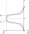
- the radiation characteristic 27 of the luminaire 1 is shown schematically.
- the intensity I of the light generated by means of an LED lamp varies with the beam angle b.
- the intensity I normalized to the maximum intensity I max is plotted over the emission angle b.
- the emission characteristic 27 is shown as a dashed line.
- a reference radiation characteristic 28 is also shown as a solid line in FIG Fig. 5 shown schematically.
- the reference emission characteristic 28 corresponds to the emission characteristic of a reference luminaire which has no cooling channels 7 on the first substrate surface 3, but is otherwise designed like the luminaire 1.
- the reference lamp the structure of which corresponds to the structure of conventional LED lamps, no part of the light generated by the LED lamps is diverted to cooling channels.
- the emission characteristic 27 has, in comparison with the reference emission characteristic 28, an increased intensity I for small amounts of the emission angle b.
- the intensity I of the emission characteristic 27 is reduced compared to the reference emission characteristic 28.
- the base angle d and / or the ratio of the refractive indices n K / n E is selected such that the condition in formula (5) is not met.
- the total reflection is therefore not guaranteed for all beam angles b.
- total reflection only takes place for light beams for whose radiation angle b applies b ⁇ 180 ° - d - sin - 1 n K n E.
- the cooling channels 7 have a different cross-sectional geometry.
- the cooling channels 7 have, for example, a polygonal cross section. Polygonal cross-sections have the advantage of flat areas of the cooling channel interface 14, so that a controlled deflection of the light incident thereon is ensured.
- FIG. 6 an alternative embodiment of a lamp 1a is shown.
- Components that are used in connection with the exemplary embodiment in Figs. 1 to 3 have already been described have the same reference numerals.
- Components that are structurally different but functionally the same have the same reference numerals with an a after them.
- the lamp 1a differs from that in the Figs. 1 to 3 lamp 1 shown only by the geometry of the cooling channels 7a.
- the cooling channels 7a have a dome-like cross section. With the dome-like cross section of the cooling channels 7a, a great height Ha is possible even with a small width Ba of the cooling channels 7a.
- the dome-shaped cross section has two side sections extending essentially in a straight line away from the first substrate surface 3. At their end facing away from the first substrate surface 3, the cooling channels 7a have a rounded tip.
- the cooling channel boundary surface 14a of the cooling channel 7a do not have a uniform base angle d.
- the base angle d is therefore defined in regions as the angle at which a surface tangent 17a of the respective region of the cooling channel interface 14a extends to the first substrate surface 3.
- the base angle d is small enough to satisfy equation (5).
- the angle of incidence c in relation to the surface normal 16a is large enough to generate total reflection, as is the case with the exemplary light beam S 5 in FIG Fig. 6 is shown.
- Fig. 7 a further alternative embodiment of a lamp 1b is shown.
- Components that are used in connection with the exemplary embodiment in Figs. 1 to 3 have already been described have the same reference numerals.
- Components that are structurally different but functionally the same have the same reference numerals with a subsequent b.
- the lamp 1b differs from that in the Figs. 1 to 3 lamp 1 shown or from the in Fig. 6 lamp 1a shown only by the geometry of the cooling channels 7b.
- the cooling channels 7b have a wedge-shaped cross section.
- the regions of the cooling channel boundary surface 14b facing the LED lighting means 5 are curved in a concave manner.
- the cooling channel 7b has an essentially lens-shaped cross section as a result. Due to the concave curvature of the regions of the cooling channel boundary surface 14b facing the LED lighting means 5, the base angle d decreases as the distance from the first substrate surface 3 decreases. this ensures that light rays with a large emission angle b strike regions of the cooling channel interface 14b which have a small base angle d.
- the cooling channels 7b enable the light generated by means of the LED lighting means 5 to be bundled in a particularly efficient manner.
- Fig. 7 an exemplary light beam S 6 is shown, which is totally reflected at the cooling channel interface 14b.
- a reflection layer is provided on the cooling channel interface in further exemplary embodiments (not shown).
- the cooling channel interface is coated with a reflective material for this purpose.
- the cooling channels have a cooling channel housing with a reflective surface. A reflective layer is particularly advantageous when the base angle d does not meet the condition of the formula (5) for all the regions of the cooling channel interface facing the respectively adjacent LED illuminant 5, for example in the case of the in Fig. 6 shown cross-sectional shape of the cooling channels 7a.
- radiators can be designed like the lights described above, the corresponding LED elements being designed to generate infrared light or UV light.
- the light to be emitted is at least partially deflected by the respective cooling channels without experiencing a change in frequency.
Landscapes
- Engineering & Computer Science (AREA)
- General Engineering & Computer Science (AREA)
- Microelectronics & Electronic Packaging (AREA)
- Led Device Packages (AREA)
- Arrangement Of Elements, Cooling, Sealing, Or The Like Of Lighting Devices (AREA)
- Non-Portable Lighting Devices Or Systems Thereof (AREA)
- Led Devices (AREA)
Description
- Die Erfindung betrifft einen Strahler zum Abstrahlen von Licht, insbesondere von sichtbaren Licht, Infrarotlicht und/oder UV-Licht. Insbesondere betrifft die Erfindung eine Leuchte zum Abstrahlen von sichtbarem Licht. Ferner betrifft die Erfindung ein Verfahren zum Abstrahlen von Licht mittels eines Strahlers.
- Aus der
EP 1 681 728 A1 ist eine Leuchte mit LED-Leuchtelementen bekannt, die ultraviolettes Licht (UV-Licht) erzeugen. Über eine Lichtwandeleinheit wird das UV-Licht in sichtbares Licht gewandelt. Zur Kühlung der Lichtwandeleinheit ist ein Wärmeableitungselement vorgesehen. Aus derDE 10 2007 054 039 A1 ist eine Leuchtdiode bekannt, bei der Flüssigkeit zur Lichtkonversion verwendet wird. DieDE 10 2010 007 687 A1 beschreibt eine LED-Lampe mit einem Wärmerohr als Kühlung. DieUS 2005/0094397 A1 beschreibt eine Lichtquelle und einen Projektor. Die DruckschriftenUS 2008/0191236 A1 ,US 2003/0052584 A1 ,US 2017/0009961 A1 ,EP 1 780 804 A1 undUS 2012/0044678 A1 beschreiben Strahler zum Abstrahlen von Licht. - Es ist die Aufgabe der vorliegenden Erfindung, einen verbesserten Strahler zur Abstrahlung von Licht zu schaffen. Es soll insbesondere ein Strahler bereitgestellt werden, der effizient und konstruktiv einfach ist.
- Diese Aufgabe ist gelöst durch einen Strahler mit den in Anspruch 1 angegebenen Merkmalen. Der Strahler weist ein Substrat mit einer Substrat-Oberfläche auf. Mindestens ein LED-Element zur Erzeugung des abzustrahlenden Lichts ist auf der Substrat-Oberfläche angeordnet. Der Strahler weist eine aktive Kühleinheit zur Kühlung des mindestens einen LED-Elements mit mindestens einem Kühlkanal für ein Kühlmittel auf. Der mindestens eine Kühlkanal ist in einem Strahlengang von zumindest einem Teil des mittels des mindestens einen LED-Elements erzeugbaren abzustrahlenden Lichts zur Umlenkung des abzustrahlenden Lichts angeordnet. Der mindestens eine Kühlkanal ist insbesondere an der Substrat-Oberfläche angeordnet. Erfindungsgemäß wurde erkannt, dass der mindestens eine zur Kühlung des mindestens einen LED-Elements verwendete Kühlkanal auch zur Umlenkung des mittels des LED-Elements erzeugbaren Lichts nutzbar ist. Hierdurch kann die Abstrahlcharakteristik des Strahlers auf einfache Weise angepasst werden. Auf die Verwendung weiterer Optiken kann verzichtet werden. Der Strahler ist effizient und weist einen einfachen Aufbau auf.
- Das durch das mindestens eine LED-Element erzeugbare Licht breitet sich im Regelfall gleichmäßig über den gesamten Raumwinkelbereich von 2π oberhalb der Substrat-Oberfläche aus. Durch die Umlenkung zumindest eines Teils des Lichts mittels des mindestens einen Kühlkanals ist die Verteilung des Lichts, insbesondere der abgedeckte Raumwinkelbereich, veränderbar. Die Umlenkung des Lichts erfolgt beispielsweise durch Reflexion und/oder Brechung des Lichts an dem mindestens einen Kühlkanal.
- Durch die Umlenkung zumindest eines Teils des Lichts durch den mindestens einen Kühlkanal ist insbesondere eine Bündelung des durch den Strahler abzustrahlenden Lichts möglich. Unter Bündelung wird verstanden, dass der Raumwinkelbereich, in welchen der Strahler Licht abstrahlt, verringert wird. Hierdurch wird die Intensität des abgestrahlten Lichts in dem abgedeckten Raumwinkelbereich erhöht. Der Strahler leuchtet einen vordefinierten Raumwinkelbereich effizient aus.
- Der Strahler dient zur Abstrahlung von Licht. Das mindestens eine LED-Element erzeugt bei Verwendung des Strahlers direkt das abzustrahlende Licht. Dies bedeutet, dass der Strahler das Licht in dem Frequenzbereich abstrahlt, der von dem mindestens einen LED-Element erzeugbar ist. Eine Umwandlung bzw. Frequenzänderung des mittels des mindestens einen LED-Elements erzeugten Lichts ist nicht erforderlich. Die Umlenkung des abzustrahlenden Lichts erfolgt ohne Änderung der Frequenz des abzustrahlenden Lichts. Erfindungsgemäß wird das mittels des mindestens einen LED-Elements erzeugte Licht nicht durch eine Lichtwandeleinheit absorbiert und in einen anderen Frequenzbereich gewandelt. Dementsprechend erfolgt die Umlenkung zumindest eines Teils des Lichts durch den mindestens einen Kühlkanal ohne Änderung der Frequenz des durch das mindestens eine LED-Element erzeugten Lichts. Die Effizienz des Strahlers ist verbessert. Das abzustrahlende Licht ist insbesondere sichtbares Licht, Infrarotlicht und/oder UV-Licht. Das abzustrahlende Licht kann beispielsweise eine Frequenz zwischen 180 THz und 3000 THz aufweisen. Sichtbares Licht ist elektromagnetische Strahlung in einem Frequenzbereich, der durch das menschliche Auge wahrgenommen werden kann. Im Allgemeinen erstreckt sich der sichtbare Frequenzbereich von etwa 400 THz bis etwa 790 THz. Zur Abstrahlung von sichtbaren Licht wird dieses direkt durch das LED-Element erzeugt. Eine Umwandlung von mittels des LED-Elements erzeugter elektromagnetischer Strahlung in sichtbares Licht erfolgt nicht. Insbesondere findet keine Umwandlung von mittels eines LED-Elements erzeugtem UV-Licht in sichtbares Licht statt. Ein Strahler zum Abstrahlen von sichtbaren Licht dient zur Beleuchtung und wird auch als Leuchte oder Luminaire bezeichnet. Bevorzugt deckt das abzustrahlende Licht den sichtbaren Frequenzbereich ab. Besonders bevorzugt ist das abzustrahlende Licht Weißlicht. Der Strahler kann eine Weißlicht-Leuchte sein.
- Strahler zur Abstrahlung von Infrarotlicht können beispielsweise zur Infrarotbeleuchtung bei Überwachungskameras, für Bilderkennungs- und Überwachungssysteme und für Datenübertragungssysteme eingesetzt werden. Besonders geeignet ist Infrarotlicht im nahen Infrarotbereich. Es weist beispielsweise eine Frequenz zwischen etwa 180 THz und etwa 399 THz auf.
- Strahler zur Abstrahlung von UV-Licht werden beispielsweise zur Desinfektion, UV-Aushärtung und UV-Trocknung eingesetzt. Besonders geeignet ist UV-Licht im nahen und mittleren UV-Bereich. Geeignetes UV-Licht kann beispielsweise eine Frequenz zwischen etwa 791 THz und etwa 3000 THz aufweisen. LED-Elemente zur Erzeugung von UV-Licht weisen regelmäßig einen nur geringen Wirkungsgrad auf, beispielsweise einen Wirkungsgrad von kleiner 20 %. Daher ist ein durch die Umlenkung, insbesondere Bündelung des abzustrahlenden Lichts erzielbarer Effizienzgewinn für Strahler zur Abstrahlung von UV-Licht besonders vorteilhaft.
- Das Substrat ist insbesondere eine Leiterplatte. Das Substrat weist eine Substrat-Oberfläche auf, auf welcher das mindestens eine LED-Element angeordnet ist. Das Substrat weist insbesondere eine weitere Substrat-Oberfläche auf, die von der ersten Substrat-Oberfläche um eine SubstratDicke beabstandet ist. Zur genaueren Unterscheidung werden im Folgenden die Substrat-Oberfläche, auf der das mindestens eine LED-Element angeordnet ist, auch als erste Substrat-Oberfläche beziehungsweise die weitere Substrat-Oberfläche, an der das mindestens eine LED-Element nicht angeordnet ist, als zweite Substrat-Oberfläche bezeichnet. Wird im Folgenden lediglich auf "die Substrat-Oberfläche" Bezug genommen, ist die Substrat-Oberfläche gemeint, auf welcher das mindestens eine LED-Element angeordnet ist.
- Der Strahler weist mindestens ein LED-Element, insbesondere mehrere LED-Elemente auf. Im Falle mehrerer LED-Elemente können diese beliebig auf der ersten Substrat-Oberfläche angeordnet sein. Bevorzugt sind mehrere LED-Elemente in regelmäßigen Abständen auf der ersten Substrat-Oberfläche angeordnet.
- Das mindestens eine LED-Element kann jeweils eine oder mehrere LEDs aufweisen. Das mindestens eine LED-Element weist insbesondere mindestens einen LED-Chip, insbesondere einen High-Power-Chip, auf. Insbesondere wenn mit dem LED-Element sichtbares Licht erzeugbar ist, wird das LED-Element auch als LED-Leuchtmittel bezeichnet. Zur Abstrahlung sichtbaren Lichts kann das LED-Leuchtmittel insbesondere einen LED-Chip aufweisen, mit dem sichtbares Licht, insbesondere ausschließlich sichtbares Licht erzeugbar ist. Alternativ oder zusätzlich hierzu kann mittels mindestens eines LED-Chips Licht im nicht sichtbaren Bereich erzeugbar sein. Gegebenenfalls kann das mindestens eine LED-Leuchtmittel eine Lichtwandeleinheit umfassen, über welche das mittels des mindestens einen LED-Chips erzeugte Licht in sichtbares Licht gewandelt wird.
- Die aktive Kühleinheit dient zur Kühlung des mindestens einen LED-Elements. Die aktive Kühleinheit weist mindestens einen Kühlkanal für ein Kühlmittel, insbesondere eine Kühlflüssigkeit, auf. Das Kühlmittel wird in dem mindestens einen Kühlkanal insbesondere durch eine Pumpe der aktiven Kühleinheit gepumpt.
- Der mindestens eine Kühlkanal ist an der bzw. benachbart zu der ersten Substrat-Oberfläche angeordnet. Der mindestens eine Kühlkanal ist an derselben Substrat-Oberfläche wie das mindestens eine LED-Element angeordnet. Die Kühlung des mindestens einen LED-Elements erfolgt direkt. Eine Wärmeabfuhr über das Substrat, beispielsweise zu an der zweiten Substrat-Oberfläche angeordneten Kühlkanälen, ist nicht nötig. Die Kühlung des mindestens einen LED-Elements ist effizient.
- Die aktive Kühleinheit weist insbesondere mehrere Kühlkanäle, bevorzugt ein Netzwerk aus Kühlkanälen, auf. Der Verlauf der Kühlkanäle kann an eine Anordnung mehrerer LED-Elemente auf der ersten Substrat-Oberfläche angepasst sein. Insbesondere verlaufen mehrere Kühlkanäle an der ersten Substrat-Oberfläche zwischen den LED-Elementen.
- Das mindestens eine LED-Element und der mindestens eine Kühlkanal sind in einer transparenten Einkapselung eingebettet. Der Strahler ist stabil und einfach fertigbar. Die transparente Einkapselung schützt das mindestens eine LED-Element und den mindestens einen Kühlkanal. Beschädigungen werden vermieden. Die Einkapselung weist insbesondere eine Abstrahl-Oberfläche auf, an welcher das mittels des Strahlers abzustrahlende Licht austritt. Die Abstrahl-Oberfläche ist insbesondere parallel zu der Substrat-Oberfläche ausgebildet. Die Abstrahl-Oberfläche ist insbesondere senkrecht zu der Hauptabstrahlrichtung.
- Die Einkapselung weist ein Silikon-Elastomer und/oder ein Harz, insbesondere ein Epoxidharz, auf. Der Strahler ist günstig und einfach fertigbar. Harze, insbesondere Epoxidharze, und/oder Silikon-Elastomere können auf einfache Weise aufgebracht und ausgehärtet werden. Die Geometrie der Einkapselung, insbesondere die Form der Abstrahl-Oberfläche, ist vorteilhafterweise an die jeweiligen Anforderungen, insbesondere die gewünschte Lampenform, einfach und flexibel anpassbar.
- Ein Strahler nach Anspruch 2 gewährleistet eine gezielte und effiziente Umlenkung, insbesondere Bündelung, des Lichts. Die Hauptabstrahlrichtung ist insbesondere senkrecht zu der Substrat-Oberfläche definiert. Eine Ablenkung in Richtung der Hauptabstrahlrichtung ist derart zu verstehen, dass eine Komponente der Ausbreitungsrichtung des Strahlengangs des Lichts in Hauptabstrahlrichtung vergrößert wird. Beispielsweise weist der Strahlengang von mittels des LED-Elements erzeugbaren Lichts einen Abstrahlwinkel b zu der Hauptabstrahlrichtung auf, wobei gilt: 0° ≤ b ≤ 90°. Für b ≠ 0° verläuft der Strahlengang nicht parallel zur Hauptabstrahlrichtung. Gegebenenfalls bewirkt die Ablenkung in Hauptabstrahlrichtung insbesondere einen abgelenkten Strahlengang, der zu der Hauptabstrahlrichtung einen Winkel b' hat, wobei gilt: 0° ≤ b' < b. Die Lichtintensität in Richtung der Hauptabstrahlrichtung ist erhöht.
- Ein Strahler nach Anspruch 3 gewährleistet eine besonders effiziente Umlenkung, insbesondere Bündelung, des abzustrahlenden Lichts. Die Reflexion an der Kühlkanal-Grenzfläche des mindestens einen Kühlkanals bewirkt eine gezielte und kontrollierte Umlenkung zumindest eines Teils des abzustrahlenden Lichts. Das an dem mindestens einen Kühlkanal reflektierte Licht dringt nicht in den Kühlkanal ein und erfährt hierdurch keine Abschwächung. Die Reflexion mindestens eines Teils des Lichts kann auch durch Totalreflexion des Lichts an der Kühlkanal-Grenzfläche erfolgen. Zusätzlich oder alternativ kann ein Bereich der Kühlkanal-Grenzfläche, auf den mindestens ein Teil des mittels des mindestens einen LED-Elements erzeugbaren Lichts trifft, verspiegelt sein.
- Ein Strahler nach Anspruch 4 gewährleistet eine direkte und effiziente Kühlung bei gleichzeitig hoher Lichtausbeute. Die benachbarte Anordnung des mindestens einen Kühlkanals und des mindestens einen LED-Elements hat weiterhin den Vorteil, dass seitlich von dem mindestens einen LED-Element ausgehendes Licht effizient umlenkbar ist. Der mindestens eine Kühlkanal kann auf der durch die Substrat-Oberfläche gebildeten Ebene direkt oder beabstandet benachbart zu dem mindestens einen LED-Element angeordnet sein. Der mindestens eine Kühlkanal ist insbesondere direkt auf der Substrat-Oberfläche angeordnet.
- Bevorzugt weisen der mindestens eine Kühlkanal und das mindestens eine LED-Element senkrecht zu der Substrat-Oberfläche keinen Überlapp auf. Besonders bevorzugt weisen der mindestens eine Kühlkanal und das mindestens eine LED-Element in der Hauptabstrahlrichtung keinen Überlapp auf. Das senkrecht zu der Substrat-Oberfläche abgestrahlte Licht, insbesondere das in Hauptabstrahlrichtung abgestrahlte Licht, erfährt keine Schwächung und/oder Umlenkung durch den mindestens einen Kühlkanal. Die Ausbeute des abzustrahlenden Lichts ist insbesondere in Hauptabstrahlrichtung verbessert.
- Ein Strahler nach Anspruch 5 gewährleistet eine effiziente Kühlung des mindestens einen LED-Elements. Zudem ist ein größerer Anteil des mittels des mindestens einen LED-Elements erzeugbaren Lichts in Richtung senkrecht zu der Substrat-Oberfläche, insbesondere in Hauptabstrahlrichtung, umlenkbar. Die Bündelung des Lichts ist weiter verbessert. Hier und im Folgenden ist unter "angrenzen" zu verstehen, dass das mindestens eine LED-Element direkt oder beabstandet benachbart zu dem mindestens einen Kühlkanal angeordnet ist.
- Bevorzugt grenzt das mindestens eine LED-Element an mindestens drei Seiten, insbesondere an allen Seiten, in der durch die Substrat-Oberfläche definierten Ebene an den mindestens einen Kühlkanal an. Besonders bevorzugt ist das mindestens eine LED-Element von dem mindestens einen Kühlkanal in der Ebene der ersten Substrat-Oberfläche vollumfänglich umgeben. An verschiedenen Seiten des LED-Elements kann der gleiche Kühlkanal, beispielsweise ein um das mindestens eine LED-Element gebogener Kühlkanal, angrenzen. Alternativ können an verschiedenen Seiten unterschiedliche Kühlkanäle an das mindestens eine LED-Element angrenzen.
- Ein Strahler nach Anspruch 6 weist eine hohe Lichtausbeute und eine präzise definierte Abstrahlcharakteristik auf. Die sich von dem jeweils benachbarten LED-Element weg erstreckenden Bereiche der Kühlkanal-Grenzfläche des mindestens einen Kühlkanals definieren ausgehend von der Substrat-Oberfläche einen sich öffnenden Abstrahlbereich bzw. Lichtkegel.
- Ein Strahler nach Anspruch 7 ist einfach und flexibel fertigbar. Die Geometrie der Kühlkanäle, insbesondere deren Querschnitt, ist flexibel festlegbar. Die als Hohlraum in der Einkapselung ausgebildeten Kühlkanäle weisen insbesondere keine zusätzliche Kühlkanal-Einhausung, insbesondere keine separat ausgebildeten Kühlkanal-Seitenwände auf. Der Wärmetransport erfolgt insbesondere direkt von dem mindestens einen LED-Element über die Einkapselung zu dem Kühlmittel in dem Kühlkanal. Die Kühlwirkung ist verbessert.
- Ein Strahler nach Anspruch 9 gewährleistet eine effiziente Umlenkung zumindest eines Teils des Lichts. Da der Brechungsindex nE der Einkapselung größer ist als der Brechungsindex nK des Kühlmittels, ist die Einkapselung ein optisch dichteres Medium als das Kühlmittel. Am Übergang vom optisch dichteren Medium der Einkapselung zu dem Kühlkanal ist somit eine Totalreflexion möglich. Hierdurch kann eine effiziente Reflexion zumindest eines Teils des Lichts an der Kühlkanal-Grenzfläche erfolgen, ohne dass eine Verspiegelung der Kühlkanal-Grenzfläche nötig ist. Hierdurch ist die Reflexion insbesondere ohne Einschränkungen des Wärmetransports durch die Kühlkanal-Grenzfläche möglich.
- Insbesondere wenn der mindestens eine Kühlkanal als Hohlraum in der Einkapselung ausgebildet ist, entspricht ein Brechungsindex des Kühlkanals dem Brechungsindex des Kühlmittels, insbesondere der Kühlflüssigkeit. Beispielhafte Kühlmittel enthalten Wasser mit einem Brechungsindex von 1,33 und/oder Ethylenglycol mit einem Brechungsindex von 1,43.
- Bevorzugt ist der Brechungsindex nE der transparenten Einkapselung größer als 1,33, insbesondere größer als 1,43, insbesondere größer als 1,45, insbesondere größer als 1,5. Die Einkapselung kann beispielsweise einen Brechungsindex nE im Bereich von 1,45 bis 1,59, insbesondere zwischen 1,45 und 1,54 aufweisen. Ein beispielhaftes Epoxidharz, das unter dem Handelsnamen "Nitto Denko NT-8524" vertrieben wird, weist einen Brechungsindex von 1,57 auf. Ein beispielhaftes Silikon-Elastomer, das unter dem Handelsnamen "Dow Corning OE-6550" vertrieben wird, weist einen Brechungsindex von 1,54 auf.
- Ein Strahler nach Anspruch 10 gewährleistet eine effiziente Umlenkung des auf die Kühlkanal-Grenzfläche des mindestens einen Kühlkanals treffenden Lichts. Der Winkel d zwischen der Oberflächentangente des dem mindestens einen LED-Element zugewandten Bereichs einer Kühlkanal-Grenzfläche und der ersten Substrat-Oberfläche bestimmt die relative Neigung des Bereichs der Kühlkanal-Grenzfläche relativ zu von dem LED-Element erzeugbaren Lichts. Abhängig von dem Winkel d erfährt Licht, das unter einem bestimmten Abstrahlwinkel b zu der Hauptabstrahlrichtung abgestrahlt wird, an der Kühlkanal-Grenzfläche eine Totalreflexion. Unter der Bedingung


- Bevorzugt ist der dem mindestens einen LED-Element zugewandte Bereich der Kühlkanal-Grenzfläche eben ausgebildet, besonders bevorzugt verläuft der gesamte dem mindestens einen LED-Element zugewandte Bereich unter dem Winkel d zur Oberfläche. Der Winkel d beschreibt gegebenenfalls den Winkel, unter welchem der gesamte dem mindestens einen LED-Element zugewandte Bereich der Kühlkanal-Grenzfläche zu der Substrat-Oberfläche verläuft. Der Winkel d wird im Folgenden auch als Basiswinkel bezeichnet.
- Ein Strahler nach Anspruch 11 ermöglicht eine kontrollierte und zuverlässige Umlenkung des Lichts. Polygonförmige Querschnitte des mindestens einen Kühlkanals weisen ebene Grenzflächen-Bereiche auf, an denen eine effiziente Umlenkung von Licht erfolgen kann. Bevorzugt weist der Querschnitt des mindestens einen Kühlkanals die Form eines Dreiecks, insbesondere eines gleichschenkligen Dreiecks, auf. Die Basis des Dreiecks liegt besonders bevorzugt parallel zu der durch die Substrat-Oberfläche gebildeten Ebene. Die Schenkel des Dreiecks erstrecken sich insbesondere von der Substrat-Oberfläche weg. Besonders bevorzugt verlaufen die Schenkel des dreieckförmigen Querschnitts des Kühlkanals unter einem Basiswinkel d zu der Substrat-Oberfläche, der die Bedingungen der Formel (2) erfüllt.
- Alternativ kann der mindestens eine Kühlkanals auch gebogene Bereiche der Kühlkanal-Grenzfläche aufweisen. Beispielsweise kann der mindestens eine Kühlkanals konvex gebogene Kühlkanal-Grenzflächenbereiche aufweisen, insbesondere kuppelförmig sein. Bevorzugt weist der mindestens eine Kühlkanal konkav gebogene Bereiche der Kühlkanal-Grenzfläche auf, insbesondere konkave Seitenflächen auf. Der Querschnitt des mindestens einen Kühlkanals kann zumindest bereichsweise linsenförmig sein. Dies ermöglicht eine besonders gute Bündelung des Lichts.
- Bevorzugt weist der mindestens eine Kühlkanal senkrecht zu der Substrat-Oberfläche eine Ausdehnung zwischen 1 mm und 20 mm, insbesondere zwischen 1 mm und 15 mm, auf. Ein derartiger Strahler ermöglicht eine effiziente Bündelung des Lichts. Die Ausdehnung des Kühlkanals senkrecht zu der Substrat-Oberfläche wird im Folgenden auch als Höhe des Kühlkanals bezeichnet. Mit steigender Höhe des Kühlkanals, insbesondere mit steigender Höhe des Kühlkanals bei gleichzeitig unveränderter, in Richtung der Substrat-Oberfläche gemessener Breite, verringert sich der Lichtkegel des mittels des Strahlers abzustrahlenden Lichts. Über die Höhe des Kühlkanals ist somit eine Anpassung der Abstrahlcharakteristik möglich.
- Allgemein kann die Abstrahlcharakteristik abhängig von der Höhe des Kühlkanals, von der Breite des Kühlkanals, von einer in Richtung der Substrat-Oberfläche gemessenen Ausdehnung des mindestens einen LED-Elements und/oder von einem in Richtung der Substrat-Oberfläche gemessenem Abstand zwischen LED-Element und benachbarten Kühlkanal sein. Zur Anpassung der Abstrahlcharakteristik an die jeweiligen Anforderungen, insbesondere zur Optimierung der Bündelung, können die oben genannten Parameter variiert und aufeinander abgestimmt werden.
- Ein Strahler nach Anspruch 12 weist eine effiziente Kühlung auf. Ethylenglycol hat sich als Kühlmittel bewährt. Ethylenglycol hat einen großen Temperaturbereich, in welchem es flüssig ist.
- Es ist eine weitere Aufgabe der Erfindung, ein Verfahren zum Abstrahlen von Licht zu verbessern, insbesondere ein Verfahren zum Abstrahlen von Licht effizient und einfach zu gestalten.
- Diese Aufgabe ist gelöst durch ein Verfahren mit den in Anspruch 13 angegebenen Schritten. Zunächst wird ein Strahler bereitgestellt. Der bereitgestellte Strahler weist ein Substrat mit einer Substrat-Oberfläche, mindestens ein auf der Substrat-Oberfläche angeordnetes LED-Element zur Erzeugung von abzustrahlendem Licht im sichtbaren Frequenzbereich und eine aktive Kühleinheit zur Kühlung des mindestens einen LED-Elements auf. Die aktive Kühleinheit weist mindestens einen Kühlkanal für ein Kühlmittel auf, der in einem Strahlengang von zumindest einem Teil des mittels des mindestens einen LED-Elements erzeugbaren, abzustrahlenden Lichts angeordnet ist. Das mindestens eine LED-Element und der mindestens eine Kühlkanal sind in einer transparenten Einkapselung eingebettet. Die Einkapselung weist ein Silikon-Elastomer und/oder ein Harz, insbesondere ein Epoxidharz, auf. Das abzustrahlende Licht wird im sichtbaren Frequenzbereich mittels des mindestens einen LED-Elements erzeugt. Das mindestens eine LED-Element wird mittels der aktiven Kühleinheit gekühlt. Zumindest ein Teil des abzustrahlenden Lichts wird mittels des mindestens einen Kühlkanals umgelenkt. Die Vorteile des Verfahrens entsprechen den Vorteilen des oben beschriebenen Strahlers. Der bereitgestellte Strahler kann insbesondere einzelne oder mehrere der oben im Zusammenhang mit dem Strahler beschriebenen Merkmale aufweisen.
- Ein Verfahren nach Anspruch 14 ermöglicht eine effiziente und gezielte Umlenkung, insbesondere Bündelung, des mittels des Strahlers abzustrahlenden Lichts.
- Ein Verfahren nach Anspruch 15 gewährleistet eine effiziente Umlenkung mindestens eines Teils des abzulenkenden Lichts. Insbesondere bei der Totalreflexion des Lichts an der Kühlkanal-Grenzfläche des mindestens einen Kühlkanals wird das Licht durch den Kühlkanal nicht absorbiert oder in diesen transmittiert. Das Licht erfährt durch den Kühlkanal keine Abschwächung. Die Intensität des mittels des Strahlers abgestrahlten Lichts ist erhöht.
- Weitere Merkmale, Vorteile und Einzelheiten der Erfindung ergeben sich aus der nachfolgenden Beschreibung mehrerer Ausführungsbeispiele. Es zeigen:
- Fig. 1
- eine Aufsicht eines schematisch dargestellten, ersten Ausführungsbeispiels einer Leuchte mit mehreren LED-Leuchtmitteln und einer aktiven Kühleinheit,
- Fig. 2
- einen Querschnitt durch die Leuchte gemäß
Fig. 1 entlang der Schnittlinie II-II, - Fig. 3
- ein Detail III der Schnittdarstellung gemäß
Fig. 2 , - Fig. 4
- einen schematischen Verfahrensablauf eines Betriebsver-fahrens für die Leuchte gemäß
Fig. 1 , - Fig. 5
- eine schematische Darstellung der Abstrahlcharakteristik der Leuchte gemäß
Fig. 1 , - Fig. 6
- einen Querschnitt durch ein zweites Ausführungsbeispiel einer Leuchte, und
- Fig. 7
- einen Querschnitt durch ein drittes Ausführungsbeispiel einer Leuchte.
- In den
Fig. 1 bis 3 ist ein erstes Ausführungsbeispiel eines Strahlers in Form einer Leuchte 1 gezeigt. Die Leuchte 1 weist ein Substrat 2 mit einer ersten Substrat-Oberfläche 3 und einer von der ersten Substrat-Oberfläche 3 um eine Substratdicke beabstandete zweite Substrat-Oberfläche 4 auf. Auf der ersten Substrat-Oberfläche 3 ist eine Mehrzahl von LED-Elementen in Form von LED-Leuchtmitteln 5 angeordnet. Die Leuchte 1 weist zudem eine aktive Kühleinheit 6 mit einem Netzwerk von auf der ersten Substrat-Oberfläche 3 angeordneten Kühlkanälen 7 auf. - In dem gezeigten Ausführungsbeispiel sind sechs LED-Leuchtmittel 5 auf der ersten Substrat-Oberfläche 3 angeordnet. Die LED-Leuchtmittel 5 sind in Form eines regelmäßigen Gitters von drei mal zwei LED-Leuchtmitteln 5 auf der ersten Substrat-Oberfläche 3 angeordnet. Anzahl und Anordnung der LED-Leuchtmittel sind nicht wesentlich und können je nach Ausführungsbeispiel variieren.
- Die LED-Leuchtmittel 5 dienen zur Erzeugung von durch die Leuchte 1 abzustrahlenden sichtbaren Lichts. Das mittels der LED-Leuchtmittel 5 erzeugbare Licht ist elektromagnetische Strahlung im sichtbaren Bereich. Dies bedeutet, das mittels der LED-Leuchtmittel 5 erzeugte Licht weist eine Frequenz bzw. eine Wellenlänge auf, die im Frequenzbereich bzw. Wellenlängenbereich des sichtbaren Lichts liegt. Die LED-Leuchtmittel 5 sind LED-Chips.
- Bei der Erzeugung von Licht mittels der LED-Leuchtmittel 5 entsteht Wärme. Die aktive Kühleinheit 6 dient zur Kühlung der LED-Leuchtmittel 5. Hierfür wird ein Kühlmittel 8 in den Kühlkanälen 7 gefördert. Das Kühlmittel 8 ist als Kühlflüssigkeit ausgeführt, welche in den
Fig. 1 und2 schematisch durch Punkte dargestellt ist. Das Kühlmittel 8 fließt in den Kühlkanälen 7 entlang der inFig. 1 symbolisch durch die Pfeile 9 angedeuteten Fließrichtung. Zum Pumpen bzw. Fördern des Kühlmittels 8 in den Kühlkanälen 7 weist die Leuchte 1 eine Pumpe 10 auf. Die Pumpe 10 ist inFig. 1 schematisch dargestellt und über eine ebenfalls schematisch dargestellte Fluidverbindung 11 mit den Kühlkanälen 7 verbunden. Bei dem gezeigten Ausführungsbeispiel ist die Pumpe 10 auf der ersten Substrat-Oberfläche 3 angeordnet. In weiteren, nicht dargestellten Ausführungsbeispielen ist die Pumpe 10 direkt in das Netzwerk der Kühlkanäle 7 integriert. In wiederum anderen, nicht dargestellten Ausführungsbeispielen ist die Pumpe 10 im Bereich der zweiten Substrat-Oberfläche 4 oder unabhängig von dem Substrat 2 angeordnet. Die Fluidverbindung 11 kann insbesondere durch das Substrat 2 oder von diesem weg führen. - Die Kühlkanäle 7 sind auf der ersten Substrat-Oberfläche 3 angeordnet. Die Kühlkanäle 7 sind in einer durch die erste Substrat-Oberfläche 3 gebildeten Ebene benachbart zu den LED-Leuchtmitteln 5 angeordnet. Die Kühlkanäle 7 grenzen umfangsseitig an die LED-Leuchtmittel 5 an. Die Kühlkanäle 7 sind umfangsseitig an allen vier Seiten der LED-Leuchtmittel 5 angeordnet. In der durch die erste Substrat-Oberfläche 3 gebildeten Ebene umschließen die Kühlkanäle 7 die einzelnen LED-Leuchtmittel 5 umfangseitig. Die Anordnung der Kühlkanäle 7 auf derselben Substrat-Oberfläche wie die LED-Leuchtmittel 5, nämlich auf der ersten Substrat-Oberfläche 3, hat insbesondere den Vorteil, dass die Kühlung der LED-Leuchtmittel 5 direkt und nicht über das Substrat 2 erfolgt. Hierdurch ist eine besonders effiziente Kühlung der LED-Leuchtmittel 5 durch die aktive Kühleinheit 6 gewährleistet.
- Die LED-Leuchtmittel 5 sowie die Kühlkanäle 7 sind in einer transparenten Einkapselung 12 eingebettet. Die Kühlkanäle 7 sind als Hohlraum in der Einkapselung 12 ausgebildet. Die Kühlkanäle 7 weisen daher keine weitere Kühlkanal-Einhausung auf. Dies erleichtert die Fertigung der Kühlkanäle 7. Die Geometrie der Kühlkanäle 7, insbesondere deren Querschnitt, ist flexibel festlegbar.
- Die Einkapselung 12 definiert eine bezogen auf die LED-Leuchtmittel 5 der ersten Substrat-Oberfläche 3 gegenüberliegende Abstrahl-Oberfläche 13. Mittels der LED-Leuchtmittel 5 erzeugtes Licht tritt aus der Abstrahl-Oberfläche 13 der Leuchte 1 aus. In dem gezeigten Ausführungsbeispiel ist die Abstrahl-Oberfläche 13 eben und parallel zu der ersten Substrat-Oberfläche 3. In anderen, nicht gezeigten Ausführungsbeispielen kann die Abstrahl-Oberfläche auch eine andere relative Lage zu der ersten Substrat-Oberfläche und/oder eine andere Form haben.
- In
Fig. 2 ist der Querschnitt der Kühlkanäle 7 der Leuchte 1 gezeigt. Die Kühlkanäle 7 weisen einen Querschnitt in Form eines gleichschenkligen Dreiecks auf. Die Basis des Dreiecks liegt in der durch die erste Substrat-Oberfläche 3 gebildeten Ebene. Die Schenkel des gleichschenkligen Dreiecks verlaufen unter einem Basiswinkel d von der ersten Substrat-Oberfläche 3 aus in Richtung der Abstrahl-Oberfläche 13. Die durch die Schenkel des gleichschenkligen Dreiecks definierten Ebenen weisen eine Flächennormale 16 und eine Oberflächentangente 17 auf. Die Oberflächentangente 17 verläuft parallel zu der Ebene des jeweiligen Schenkels. Der Basiswinkel d ist daher als der Winkel definiert, in welchem die Oberflächentangente 17 zu der ersten Substrat-Oberfläche 3 verläuft. Die Kühlkanäle 7 weisen in Richtung senkrecht zu der ersten Substrat-Oberfläche 3 eine Höhe H auf. - Die Kühlkanäle 7 weisen zu der Einkapselung 12 eine Kühlkanal-Grenzfläche 14 auf. In dem gezeigten Ausführungsbeispiel, in welchem die Kühlkanäle 7 durch Hohlräume in der Einkapselung 12 gebildet sind, ist die Kühlkanal-Grenzfläche 14 durch einen Übergang zwischen der Einkapselung 12 zu dem Kühlmittel 8 gebildet. In anderen, nicht dargestellten Ausführungsbeispielen kann die Kühlkanal-Grenzfläche 14 auch durch eine Kühlkanal-Einhausung ausgebildet sein.
- Die Kühlkanal-Grenzfläche 14 verläuft entlang der Schenkel des dreieckförmigen Querschnitts der Kühlkanäle 7. Wie in
Fig. 2 zu sehen ist, erstreckt sich ein einem der LED-Leuchtmittel 5 zugewandter Bereich der Kühlkanal-Grenzfläche 14 mit zunehmenden Abstand von der ersten Substrat-Oberfläche 3 von dem jeweils benachbarten LED-Leuchtmittel 5 weg. Mit anderen Worten nimmt ein in der Ebene der ersten Substrat-Oberfläche 3 gemessener Abstand der Kühlkanal-Grenzfläche 14 zu dem jeweils benachbarten LED-Leuchtmittel 5 mit zunehmendem Abstand senkrecht zu der ersten Substrat-Oberfläche 3 zu. Hierdurch definieren die Kühlkanäle 7, insbesondere deren Kühlkanal-Grenzflächen 14, einen sich von der ersten Substrat-Oberfläche 3 hin zu der Abstrahl-Oberfläche 13 öffnenden Lichtkegel für mittels der LED-Leuchtmittel 5 erzeugbares Licht. - Mit Bezug auf die
Fig. 2 und3 wird im Folgenden die Abstrahlung von Licht mittels der Leuchte 1 beschrieben. Aufgrund der Anordnung der Kühlkanäle 7 ermöglichen diese eine Bündelung des mittels der LED-Leuchtmittel 5 erzeugten Lichts. - Senkrecht zu der ersten Substrat-Oberfläche 3 ist eine Hauptabstrahlrichtung 15 definiert. Bei dem gezeigten Ausführungsbeispiel steht die Hauptabstrahlrichtung 15 senkrecht auf die Abstrahl-Oberfläche 13. Die LED-Leuchtmittel 5 erzeugen Licht, welches von den LED-Leuchtmitteln 5 über den gesamten Raumwinkelbereich von 2π oberhalb der ersten Substrat-Oberfläche 3 abgestrahlt wird. Durch Pfeile sind in
Fig. 2 Strahlengänge beispielhafter Lichtstrahlen Si mit i = 1, 2, 3, 4, die durch das inFig. 2 mittig dargestellte LED-Leuchtmittel 5 erzeugbar sind. - Die Kühlkanäle 7 weisen in Richtung der Hauptabstrahlrichtung 15 keinen Überlapp mit den LED-Leuchtmitteln 5 auf. Die Kühlkanäle 7 sind daher nicht in einem Strahlengang von Lichtstrahlen angeordnet, die im Wesentlichen in Richtung der Hauptabstrahlrichtung 15 verlaufen. Von den beispielhaft in
Fig. 2 gezeigten Strahlengängen treffen die Lichtstrahlen S1, S2, S3 nicht auf die Kühlkanäle 7. Die Lichtstrahlen S1, S2, S3 gelangen direkt an die Abstrahl-Oberfläche 13 und werden von dort in eine Umgebung der Leuchte 1 abgestrahlt. Die Kühlkanäle 7 sind jedoch in einem Strahlengang von zumindest einem Teil des mittels des mindestens einen LED-Leuchtmittels 5 erzeugten Lichts angeordnet. Von den beispielhaft inFig. 2 gezeigten Lichtstrahlen trifft der Lichtstrahl S4 auf den dem mittig dargestellten LED-Leuchtmittel 5 benachbarten Bereich der Kühlkanal-Grenzfläche 14 des inFig. 2 rechts dargestellten Kühlkanals 7. Der Lichtstrahl S4 wird an der Kühlkanal-Grenzfläche 14 in Richtung der Abstrahl-Oberfläche 13 reflektiert. Der reflektierte Lichtstrahl ist in denFig. 2 und3 als Lichtstrahl S'4 eingezeichnet. Das auf die Kühlkanäle 7 treffende Licht wird an der Kühlkanal-Grenzfläche 14 umgelenkt. Die Umlenkung wird im Folgenden anhand derFig. 3 im Detail beschrieben. - Der Lichtstrahl S4 weist zu der Hauptabstrahlrichtung 15 einen Abstrahlwinkel b auf. Der Abstrahlwinkel b beträgt im Allgemeinen zwischen 0° und 90°. Beim Auftreffen auf die Kühlkanal-Grenzfläche 14 weist der Lichtstrahl S4 zu einer Flächennormalen 16 der Kühlkanal-Grenzfläche 14 einen Einfallswinkel c auf. Der reflektierte Lichtstrahl S'4 weist zu der Flächennormalen 16 einen Ausfallswinkel c' auf, wobei der Ausfallswinkel c' betragsmäßig dem Einfallswinkel c entspricht. Der Winkel zwischen dem reflektierten Lichtstrahl S'4 und der Hauptabstrahlrichtung 15 wird mit b' bezeichnet. Aufgrund der Reflexion an der sich von dem LED-Leuchtmittel 5 weg erstreckenden Kühlkanal-Grenzfläche 14 gilt für den Winkel b': 0° ≤ b' < b. Aufgrund der Reflexion an der Kühlkanal-Grenzfläche 14 ist der Winkel b' des reflektierten Lichtstrahls S'4 zu der Hauptabstrahlrichtung 15 im Vergleich zu dem Abstrahlwinkel b des Lichtstrahls S4 verringert. Das an der Kühlkanal-Grenzfläche 14 reflektierte Licht erfährt eine Ablenkung in Richtung der Hauptabstrahlrichtung 15. Die Kühlkanäle 7 bewirken eine Umlenkung und Bündelung des mittels der LED-Leuchtmittel 5 erzeugten Lichts in Hauptabstrahlrichtung 15. Die Lichtintensität in Richtung der Hauptabstrahlrichtung 15 ist vergrößert.
- Im Regelfall wird elektromagnetische Strahlung beim Auftreffen auf eine Grenzfläche nicht nur reflektiert, sondern wird teilweise durch die Grenzfläche transmittiert. In
Fig. 3 ist daher auch ein transmittierter Lichtstrahl


- Der Einfallswinkel c ist abhängig von dem Abstrahlwinkel b und dem Basiswinkel d. Je kleiner der Abstrahlwinkel b ist, desto größer ist der Einfallswinkel c. Bei dem gezeigten Ausführungsbeispiel ist der Basiswinkel d derart gewählt, dass unabhängig von dem Abstrahlwinkel b, insbesondere also auch für den Abstrahlwinkel b = 90°, der Einfallswinkel c zur Totalreflexion führt. Für den Basiswinkel d gilt daher die Bedingung:

- Der Brechungsindex der transparenten Einkapselung 12 liegt im gezeigten Ausführungsbeispiel zwischen 1,45 und 1,59. Bei dem gezeigten Ausführungsbeispiel wird für die transparente Einkapselung 12 ein Epoxidharz verwendet. Als Einkapselung wird beispielsweise das unter dem Handelsnamen "Nitto Denko NT-8524" vertriebene Epoxidharz verwendet, das einen Brechungsindex von 1,57 aufweist.
- Als Kühlmittel 8 sind verschiedene Fluide, insbesondere Flüssigkeiten einsetzbar. Ein beispielhaftes Kühlmittel ist Ethylenglycol, das einen Brechungsindex von 1,43 aufweist. Für nE = 1,57 und nK = 1,43 ergibt sich gemäß Formel (5) für den Basiswinkel d, ab welchem die Totalreflexion unabhängig von dem Abstrahlwinkel b gewährleistet ist: d ≤ 21,7°. Ein alternatives Kühlmittel ist Wasser, das einen Brechungsindex von 1,33 hat. In diesem Fall ergibt sich für den Basiswinkel d, für den die Totalreflexion unabhängig von dem Abstrahlwinkel b gewährleistet ist: d ≤ 32°.
- In alternativen, nicht gezeigten Ausführungsbeispielen ist die transparente Einkapselung aus einem Silikon-Elastomer. Ein beispielhaftes Silikon-Elastomer, das unter dem Handelsnamen "Dow Corning OE-6550" vertrieben wird, hat den Brechungsindex 1,54.
- Die Kühlkanäle 7 weisen senkrecht zu der ersten Substrat-Oberfläche 3 und damit in Hauptabstrahlrichtung 15 eine Höhe H auf. Die Höhe H ist abhängig von einer Breite B der Basis des dreieckigen Querschnitts der Kühlkanäle 7 und dem Basiswinkel d. Mit Vergrößerung des Basiswinkels d und/oder Erhöhung der Breite B vergrößert sich die Höhe H. Mit steigender Höhe trifft ein größerer Anteil des mittels der LED-Leuchtmittel 5 erzeugten Lichts auf die Kühlkanal-Grenzfläche 14 und wird an dieser umgelenkt. Die mittels der Kühlkanäle 7 bewirkte Bündelungswirkung ist daher abhängig von der Höhe H und dem Basiswinkel d des Querschnitts des Kühlkanals 7. Die Lichtintensität und Bündelung des durch die Leuchte 1 abgestrahlten Lichts entlang der Hauptabstrahlrichtung 15 ist daher durch die Geometrie der Kühlkanäle 7 einstellbar. Die Höhe H beträgt beispielsweise zwischen 1 mm und 20 mm, insbesondere zwischen 1 mm und 15 mm, bevorzugt etwa 10 mm. Die Breite der Kühlkanäle 7 beträgt beispielsweise zwischen 5 mm und 50 mm, insbesondere zwischen5 mm und 40 mm, bevorzugt etwa 20 mm. Der Basiswinkel d beträgt beispielsweise zwischen 0° und 90°, insbesondere zwischen 10° und 80°, insbesondere zwischen 15° und 45°, bevorzugt etwa 35°.
- Weitere Parameter zur Beeinflussung der Abstrahlcharakteristik sind die in Richtung der ersten Substrat-Oberfläche 3 gemessene Ausdehnung L der LED-Leuchtmittel 5 sowie der in Richtung der ersten Substrat-Oberfläche 3 gemessene Abstand A zwischen den Kühlkanälen 7 und den LED-Leuchtmitteln 5 (vgl.
Fig. 2 ). Der Abstand A kann beispielsweise zwischen 0 mm und 5 mm, insbesondere zwischen 0,5 mm und 2 mm, insbesondere etwa 1 mm betragen. Bei einem Abstand A = 0 mm sind die LED-Leuchtmittel 5 und die Kühlkanäle 7 direkt zueinander benachbart auf der ersten Substrat-Oberfläche 3 angeordnet. Eine beispielhafte Ausdehnung L der LED-Leuchtmittel 5 kann zwischen 0,1 mm und 5 mm, insbesondere zwischen 0,2 mm und 2 mm, insbesondere etwa 1 mm betragen. In einem exemplarischen Ausführungsbeispiel beträgt die Ausdehnung der LED-Leuchtmittel 5 etwa 1 mm und der Abstand zwischen LED-Leuchtmittel 5 und den benachbarten Kühlkanälen 7 jeweils 1 mm. In dem exemplarischen Ausführungsbeispiel beträgt der Basiswinkel d = 35°, die Höhe H = 7,5 mm und die Breite B = 21 mm. - In
Fig. 4 ist der Ablauf eines Betriebsverfahrens 20 für die Leuchte 1 schematisch dargestellt. In einem Bereitstellungsschritt 21 wird die Leuchte 1 bereitgestellt. - An den Bereitstellungsschritt 21 schließt sich ein Abstrahlschritt 22 an. In dem Abstrahlschritt 22 wird mit Hilfe der Leuchte 1 Licht abgestrahlt. Das abzustrahlende Licht wird in einem Lichterzeugungsschritt 23 mit Hilfe der LED-Leuchtmittel 5 erzeugt. Das mit Hilfe der LED-Leuchtmittel 5 erzeugte Licht ist im sichtbaren Bereich. In einem Umlenkschritt 24 wird zumindest ein Teil des mit Hilfe der LED-Leuchtmittel 5 erzeugten Lichts durch die Kühlkanäle 7 umgelenkt. Hierbei wird das Licht an einer Kühlkanal-Grenzfläche 14 reflektiert, insbesondere totalreflektiert.
- In einem Kühlschritt 25 werden die LED-Leuchtmittel 5 mit Hilfe der aktiven Kühleinheit 6 gekühlt. Hierbei wird Kühlmittel 8 durch die Kühlkanäle 7 mit Hilfe der Pumpe 10 gepumpt.
- In
Fig. 5 wird schematisch die Abstrahlcharakteristik 27 der Leuchte 1 gezeigt. Die Intensität I des mittels eins LED-Leuchtmittels erzeugten Lichts variiert mit dem Abstrahlwinkel b. Zur Ermittlung der Abstrahlcharakteristik 27 wird die auf die maximale Intensität Imax normierte Intensität I über den Abstrahlwinkel b aufgetragen. Die Abstrahlcharakteristik 27 ist als gestrichelte Linie dargestellt. Zu Vergleichszwecken ist auch eine Referenz-Abstrahlcharakteristik 28 als durchgezogene Linie inFig. 5 schematisch dargestellt. Die Referenz-Abstrahlcharakteristik 28 entspricht der Abstrahlcharakteristik einer Referenz-Leuchte, die keine Kühlkanäle 7 auf der ersten Substrat-Oberfläche 3 aufweist, ansonsten aber wie die Leuchte 1 ausgebildet ist. Bei der Referenz-Leuchte, deren Aufbau dem Aufbau marktüblicher LED-Lampen entspricht, findet keine Umlenkung eines Teils des mittels der LED-Leuchtmittel erzeugten Lichts an Kühlkanälen statt. Der Vergleich der Abstrahlcharakteristik 27 mit der Referenz-Abstrahlcharakteristik 28 zeigt deutlich, dass durch die Umlenkung eines Teils des mittels der LED-Leuchtmittel 5 erzeugten Lichts an den Kühlkanälen 7 eine Bündelung des Lichts um die Hauptabstrahlrichtung 15, für die b = 0° gilt, erfolgt. Insbesondere weist die Abstrahlcharakteristik 27 im Vergleich mit der Referenz-Abstrahlcharakteristik 28 eine erhöhte Intensität I für kleine Beträge des Abstrahlwinkels b auf. Für größere Beträge des Abstrahlwinkels b, insbesondere in den Bereichen nahe von 90° bzw. - 90° ist die Intensität I der Abstrahlcharakteristik 27 gegenüber der Referenz-Abstrahlcharakteristik 28 verringert. - In weiteren, nicht gezeigten Ausführungsbeispielen ist der Basiswinkel d und/oder das Verhältnis der Brechungsindizes nK/nE derart gewählt, dass die Bedingung in Formel (5) nicht erfüllt ist. Die Totalreflexion ist daher nicht für alle Abstrahlwinkel b gewährleistet. Bei derartigen Ausführungsbeispielen erfolgt die Totalreflexion nur für Lichtstrahlen, für deren Abstrahlwinkel b gilt

- In weiteren Ausführungsbeispielen weisen die Kühlkanäle 7 eine andere Querschnittsgeometrie auf. Die Kühlkanäle 7 weisen beispielsweise einen polygonförmigen Querschnitt auf. Polygonförmige Querschnitte haben den Vorteil ebener Bereiche der Kühlkanal-Grenzfläche 14, sodass eine kontrollierte Umlenkung des hierauf einfallenden Lichts gewährleistet ist.
- In
Fig. 6 ist ein alternatives Ausführungsbeispiel einer Leuchte 1a gezeigt. Komponenten, die im Zusammenhang mit dem Ausführungsbeispiel in denFig. 1 bis 3 bereits beschrieben wurden, tragen die gleichen Bezugszeichen. Konstruktiv unterschiedliche, jedoch funktional gleiche Komponenten tragen das gleiche Bezugszeichen mit einem nachgestellten a. - Die Leuchte 1a unterscheidet sich von der in den
Fig. 1 bis 3 gezeigten Leuchte 1 nur durch die Geometrie der Kühlkanäle 7a. Die Kühlkanäle 7a weisen einen kuppelartigen Querschnitt auf. Mit dem kuppelartigen Querschnitt der Kühlkanäle 7a ist eine große Höhe Ha auch bei geringer Breite Ba der Kühlkanäle 7a möglich. Der kuppelförmige Querschnitt weist zwei im Wesentlichen geradlinig sich von der ersten Substrat-Oberfläche 3 weg erstreckende Seitenabschnitte auf. An ihrem der ersten Substrat-Oberfläche 3 abgewandten Ende weisen die Kühlkanäle 7a eine abgerundete Spitze auf. - Im Gegensatz zu dem in
Fig. 3 gezeigten, dreieckigen Querschnitt des Kühlkanals 7 weisen Seitenwände die Kühlkanal-Grenzfläche 14a des Kühlkanals 7a keinen einheitlichen Basiswinkel d auf. Der Basiswinkel d ist daher bereichsweise definiert als der Winkel, unter welchem eine Oberflächentangente 17a des jeweiligen Bereichs der Kühlkanal-Grenzfläche 14a zu der ersten Substrat-Oberfläche 3 verläuft. - Im Bereich der Spitze der Kühlkanäle 7a ist der Basiswinkel d klein genug, die Gleichung (5) zu erfüllen. In diesem Bereich ist der Einfallswinkel c in Bezug auf die Flächennormale 16a groß genug, um Totalreflexion zu erzeugen, wie dies an dem beispielhaften Lichtstrahl S5 in
Fig. 6 dargestellt ist. - In
Fig. 7 ist ein weiteres alternatives Ausführungsbeispiel einer Leuchte 1b gezeigt. Komponenten, die im Zusammenhang mit dem Ausführungsbeispiel in denFig. 1 bis 3 bereits beschrieben wurden, tragen die gleichen Bezugszeichen. Konstruktiv unterschiedliche, jedoch funktional gleiche Komponenten tragen das gleiche Bezugszeichen mit einem nachgestellten b. - Die Leuchte 1b unterscheidet sich von der in den
Fig. 1 bis 3 gezeigten Leuchte 1 bzw. von der inFig. 6 gezeigten Leuchte 1a nur durch die Geometrie der Kühlkanäle 7b. Die Kühlkanäle 7b weisen einen keilförmigen Querschnitt auf. Die den LED-Leuchtmitteln 5 zugewandten Bereiche der Kühlkanal-Grenzfläche 14b sind konkav gekrümmt. Insgesamt weist der Kühlkanal 7b hierdurch einen im Wesentlichen linsenförmigen Querschnitt auf. Durch die konkave Krümmung der den LED-Leuchtmitteln 5 zugewandten Bereiche der Kühlkanal-Grenzfläche 14b nimmt der Basiswinkel d mit abnehmendem Abstand von der ersten Substrat-Oberfläche 3 ab. Dies gewährleistet, dass Lichtstrahlen mit großem Abstrahlwinkel b auf Bereiche der Kühlkanal-Grenzfläche 14b treffen, die einen kleinen Basiswinkel d aufweisen. Hierdurch kann auf effiziente Weise die Bedingung für Totalreflexion an der Kühlkanal-Grenzfläche 14b gewährleistet werden. Die Kühlkanäle 7b ermöglichen eine besonders effiziente Bündelung des mittels der LED-Leuchtmittel 5 erzeugten Lichts. InFig. 7 ist ein beispielhafter Lichtstrahl S6 gezeigt, der an der Kühlkanal-Grenzfläche 14b total reflektiert wird. - Um die Reflexion der Lichtstrahlen an den Kühlkanälen zu verbessern, ist in weiteren, nicht dargestellten Ausführungsbeispielen eine Reflexionsschicht an der Kühlkanal-Grenzfläche vorhanden. In einigen Ausführungsbeispielen ist die Kühlkanal-Grenzfläche hierzu mit einem reflektierenden Material beschichtet. In wiederum anderen Ausführungsbeispielen weisen die Kühlkanäle eine Kühlkanal-Einhausung mit reflektierender Oberfläche auf. Eine Reflexionsschicht ist insbesondere dann von Vorteil, wenn der Basiswinkel d nicht für alle dem jeweils benachbarten LED-Leuchtmittel 5 zugewandte Bereiche der Kühlkanal-Grenzfläche die Bedingung der Formel (5) erfüllt, beispielsweise bei der in
Fig. 6 gezeigten Querschnittsform der Kühlkanäle 7a. - Alternative Ausführungsbeispiele betreffen Strahler zur Abstrahlung von Infrarotlicht oder UV-Licht. Die Strahler können wie die oben beschriebenen Leuchten ausgebildet sein, wobei die entsprechenden LED-Elemente zur Erzeugung von Infrarotlicht bzw. UV-Licht ausgelegt sind. Das abzustrahlende Licht wird durch die jeweiligen Kühlkanäle zumindest teilweise umgelenkt ohne eine Frequenzänderung zu erfahren.
Claims (15)
- Strahler zum Abstrahlen von Licht, aufweisend- ein Substrat (2) mit einer Substrat-Oberfläche (3),- mindestens ein auf der Substrat-Oberfläche (3) angeordnetes LED-Element (5) zur Erzeugung des abzustrahlenden Lichts, und- eine aktive Kühleinheit (6) zur Kühlung des mindestens einen LED-Elements (5) mit mindestens einem Kühlkanal (7; 7a; 7b) für ein Kühlmittel (8),wobei der mindestens eine Kühlkanal (7; 7a; 7b) in einem Strahlengang (S4; S5; S6) von zumindest einem Teil des mittels des mindestens einen LED-Elements (5) erzeugbaren abzustrahlenden Lichts zur Umlenkung des abzustrahlenden Lichts angeordnet ist,
wobei die Umlenkung des abzustrahlenden Lichts ohne Änderung einer Frequenz des abzustrahlenden Lichts erfolgt,
wobei das mindestens eine LED-Element (5) und der mindestens eine Kühlkanal (7; 7a; 7b) in einer transparenten Einkapselung (12) eingebettet sind,
dadurch gekennzeichnet, dass die Einkapselung (12) ein Silikon-Elastomer und/oder ein Harz aufweist. - Strahler nach Anspruch 1, dadurch gekennzeichnet,
dass durch den mindestens einen Kühlkanal (7; 7a; 7b) zumindest ein Teil des abzustrahlenden Lichts in Richtung einer vordefinierten Hauptabstrahlrichtung (15), insbesondere einer senkrecht zu der Substrat-Oberfläche (3) definierten Hauptabstrahlrichtung (15), ablenkbar ist. - Strahler nach mindestens einem der vorgenannten Ansprüche, dadurch gekennzeichnet,
dass eine Kühlkanal-Grenzfläche (14; 14a; 14b) des mindestens einen Kühlkanals (7; 7a; 7b) zumindest bereichsweise derart ausgebildet ist, dass zumindest ein Teil des abzustrahlenden Lichts an der Kühlkanal-Grenzfläche (14; 14a; 14b) reflektiert wird. - Strahler mindestens nach einem der vorgenannten Ansprüche, dadurch gekennzeichnet,
dass der mindestens eine Kühlkanal (7; 7a; 7b) auf einer durch die Substrat-Oberfläche (3) gebildeten Ebene benachbart zu dem mindestens einen LED-Element (5) angeordnet ist. - Strahler nach Anspruch 4, dadurch gekennzeichnet,
dass das mindestens eine LED-Element (5) an mindestens zwei Seiten auf der durch die Substrat-Oberfläche (3) definierten Ebene an den mindestens einen Kühlkanal (7; 7a; 7b) angrenzt. - Strahler nach einem der Ansprüche 4 oder 5, dadurch gekennzeichnet,
dass ein dem jeweils benachbarten LED-Element (5) zugewandter Bereich einer Kühlkanal-Grenzfläche (14; 14a; 14b) des mindestens einen Kühlkanals (7; 7a; 7b) sich mit zunehmendem Abstand von der Substrat-Oberfläche (3) von dem benachbarten LED-Element (5) wegerstreckt. - Strahler nach mindestens einem der vorgenannten Ansprüche, dadurch gekennzeichnet,
dass der mindestens eine Kühlkanal (7; 7a; 7b) als Hohlraum in der Einkapselung (12) ausgebildet ist. - Strahler nach mindestens einem der vorgenannten Ansprüche, dadurch gekennzeichnet,
dass die Einkapselung (12) ein Epoxidharz aufweist. - Strahler nach mindestens einem der vorgenannten Ansprüche, dadurch gekennzeichnet,
dass ein Brechungsindex nE der transparenten Einkapselung (12) größer als ein Brechungsindex nK eines in dem mindestens einen Kühlkanal (7; 7a; 7b) enthaltenen Kühlmittels (8) ist. - Strahler nach Anspruch 9, dadurch gekennzeichnet,
dass eine Oberflächentangente (17; 17a; 17b) eines dem mindestens einen LED-Element (5) zugewandten Bereichs einer Kühlkanal-Grenzfläche (14; 14a; 14b) des mindestens einen Kühlkanals (7; 7a; 7b) unter einem Winkel d zu der Substrat-Oberfläche (3) verläuft, wobei gilt:
- Strahler nach mindestens einem der vorgenannten Ansprüche, dadurch gekennzeichnet,
dass ein Querschnitt des mindestens einen Kühlkanals (7) polygonförmig, insbesondere dreieckig, ist. - Strahler nach mindestens einem der vorgenannten Ansprüche, dadurch gekennzeichnet,
dass der mindestens eine Kühlkanal (7; 7a; 7b) ein Ethylenglycol aufweisendes Kühlmittel (8) enthält. - Verfahren zum Abstrahlen von Licht mittels eines Strahlers mit den Schritten:- Bereitstellen eines Strahlers (1; 1a; 1b), aufweisend-- ein Substrat (2) mit einer Substrat-Oberfläche (3),-- mindestens ein auf der Substrat-Oberfläche (3) angeordnetes LED-Element (5) zur Erzeugung von abzustrahlenden Licht, und-- eine aktive Kühleinheit (6) zur Kühlung des mindestens einen LED-Elements (5) mit mindestens einem Kühlkanal (7; 7a; 7b) für ein Kühlmittel (8),wobei der mindestens eine Kühlkanal (7; 7a; 7b) in einem Strahlengang (S4; S5; S6) von zumindest einem Teil des mittels des mindestens einen LED-Elements (5) erzeugbaren abzustrahlenden Lichts angeordnet ist,
wobei das mindestens eine LED-Element (5) und der mindestens eine Kühlkanal (7; 7a; 7b) in einer transparenten Einkapselung (12) eingebettet sind, und
wobei die Einkapselung (12) ein Silikon-Elastomer und/oder ein Harz aufweist,- Erzeugen des abzustrahlenden Lichts mittels des mindestens einen LED-Elements (5),- Kühlen des mindestens einen LED-Elements (5) mittels der aktiven Kühleinheit (6) und- Umlenken mindestens eines Teils des abzustrahlenden Lichts mittels des mindestens einen Kühlkanals (7; 7a; 7b),wobei die Umlenkung des abzustrahlenden Lichts ohne Änderung einer Frequenz des abzustrahlenden Lichts erfolgt. - Verfahren nach Anspruch 13, dadurch gekennzeichnet,
dass mindestens ein Teil des abzustrahlenden Lichts durch den mindestens einen Kühlkanal (7; 7a; 7b) in Richtung einer vordefinierten Hauptabstrahlrichtung (15), insbesondere in Richtung einer senkrecht zu der Substrat-Oberfläche (3) definierten Hauptabstrahlrichtung (15), abgelenkt wird. - Verfahren nach einem der Ansprüche 13 oder 14, dadurch gekennzeichnet,
dass die Umlenkung mindestens eines Teils des abzustrahlenden Lichts durch Reflexion, insbesondere Totalreflexion an einer Kühlkanal-Grenzfläche (14; 14a; 14b) des mindestens einen Kühlkanals (7; 7a; 7b) erfolgt.
Applications Claiming Priority (2)
| Application Number | Priority Date | Filing Date | Title |
|---|---|---|---|
| DE102019213150.6A DE102019213150A1 (de) | 2019-08-30 | 2019-08-30 | Strahler und Verfahren zum Abstrahlen von Licht |
| PCT/EP2020/071189 WO2021037459A1 (de) | 2019-08-30 | 2020-07-28 | Strahler und verfahren zum abstrahlen von licht |
Publications (2)
| Publication Number | Publication Date |
|---|---|
| EP3810988A1 EP3810988A1 (de) | 2021-04-28 |
| EP3810988B1 true EP3810988B1 (de) | 2021-08-04 |
Family
ID=71846393
Family Applications (1)
| Application Number | Title | Priority Date | Filing Date |
|---|---|---|---|
| EP20747390.1A Active EP3810988B1 (de) | 2019-08-30 | 2020-07-28 | Strahler und verfahren zum abstrahlen von licht |
Country Status (6)
| Country | Link |
|---|---|
| US (1) | US12191436B2 (de) |
| EP (1) | EP3810988B1 (de) |
| CN (1) | CN114342097B (de) |
| DE (1) | DE102019213150A1 (de) |
| TW (1) | TWI823021B (de) |
| WO (1) | WO2021037459A1 (de) |
Families Citing this family (1)
| Publication number | Priority date | Publication date | Assignee | Title |
|---|---|---|---|---|
| CN117389051A (zh) * | 2023-11-10 | 2024-01-12 | 业成光电(深圳)有限公司 | 图像生成单元、抬头显示装置以及车辆 |
Family Cites Families (16)
| Publication number | Priority date | Publication date | Assignee | Title |
|---|---|---|---|---|
| JP3656715B2 (ja) * | 1999-07-23 | 2005-06-08 | 松下電工株式会社 | 光源装置 |
| JP4027063B2 (ja) | 2001-09-17 | 2007-12-26 | 松下電器産業株式会社 | 照明装置 |
| JP3753137B2 (ja) * | 2003-09-04 | 2006-03-08 | セイコーエプソン株式会社 | 光源装置、及びプロジェクタ |
| WO2005038935A1 (ja) | 2003-10-15 | 2005-04-28 | Nichia Corporation | 発光装置 |
| JP4300418B2 (ja) * | 2004-04-30 | 2009-07-22 | 信越化学工業株式会社 | エポキシ・シリコーン混成樹脂組成物及び発光半導体装置 |
| JP5320060B2 (ja) | 2005-04-27 | 2013-10-23 | コーニンクレッカ フィリップス エヌ ヴェ | 発光半導体デバイス用冷却装置及びそのような冷却装置の製造方法 |
| EP1780804A1 (de) | 2005-10-25 | 2007-05-02 | L&C Lighting Technology Corp. | Leuchtdiodenbauteil mit einer aktiven Kühlungseinrichtung |
| DE102007054039A1 (de) * | 2007-09-12 | 2009-03-19 | Osram Opto Semiconductors Gmbh | Leuchtdiode und Verfahren zur Einstellung des Farbortes bei einer Leuchtdiode |
| DE102010001007B4 (de) * | 2010-01-19 | 2013-01-03 | Osram Ag | Leuchte zum Ausleuchten eines Zielbereiches mittels Rückwärtsreflexion von Licht eines Leuchtdiodenmoduls an einem Reflektor |
| DE102010007687A1 (de) * | 2010-02-08 | 2011-08-11 | Siemens Aktiengesellschaft, 80333 | LED-Lampe mit Wärmerohr als Kühlung |
| US8596826B2 (en) * | 2010-08-23 | 2013-12-03 | Abl Ip Holding Llc | Active cooling systems for optics |
| DE102011003989A1 (de) | 2011-02-11 | 2012-08-16 | Osram Ag | Leuchtvorrichtung |
| KR20160030225A (ko) * | 2013-07-10 | 2016-03-16 | 골든아이 인코퍼레이티드 | 자냉식 광원 |
| WO2017008042A1 (en) | 2015-07-08 | 2017-01-12 | Air Motion Systems, Inc. | Led module |
| EP3475620A1 (de) * | 2016-06-27 | 2019-05-01 | Electrolux Appliances Aktiebolag | Haushaltsgerät mit einer beleuchtungsvorrichtung und einem kühlkanal |
| US10388838B2 (en) * | 2016-10-19 | 2019-08-20 | Genesis Photonics Inc. | Light-emitting device and manufacturing method thereof |
-
2019
- 2019-08-30 DE DE102019213150.6A patent/DE102019213150A1/de not_active Withdrawn
-
2020
- 2020-07-28 CN CN202080061271.1A patent/CN114342097B/zh active Active
- 2020-07-28 WO PCT/EP2020/071189 patent/WO2021037459A1/de not_active Ceased
- 2020-07-28 EP EP20747390.1A patent/EP3810988B1/de active Active
- 2020-07-28 US US17/629,195 patent/US12191436B2/en active Active
- 2020-08-14 TW TW109127795A patent/TWI823021B/zh active
Also Published As
| Publication number | Publication date |
|---|---|
| EP3810988A1 (de) | 2021-04-28 |
| TW202108935A (zh) | 2021-03-01 |
| CN114342097A (zh) | 2022-04-12 |
| US20220246817A1 (en) | 2022-08-04 |
| WO2021037459A1 (de) | 2021-03-04 |
| US12191436B2 (en) | 2025-01-07 |
| DE102019213150A1 (de) | 2021-03-04 |
| CN114342097B (zh) | 2025-11-04 |
| TWI823021B (zh) | 2023-11-21 |
Similar Documents
| Publication | Publication Date | Title |
|---|---|---|
| EP1805815B1 (de) | Beleuchtungseinrichtung, kfz-scheinwerfer und verfahren zur herstellung einer beleuctungseinrichtung | |
| EP1807877B1 (de) | Leuchtdioden-anordnung mit farbkonversions-material | |
| EP1630576B1 (de) | Leuchtmittel mit vorgegebener Abstrahlcharakteristik und Primäroptikelement für ein Leuchtmittel | |
| EP3108174A1 (de) | Beleuchtungsvorrichtung mit konversionseinrichtung | |
| DE102015122343B4 (de) | Led-lichtquelle, hintergrundbeleuchtungsmodul und flüssigkristallanzeigevorrichtung | |
| DE102013217319B4 (de) | Beleuchtungseinrichtung | |
| DE102012223854A1 (de) | Remote-Phosphor-Konvertereinrichtung | |
| DE102013200521B4 (de) | Primäroptikeinrichtung für KFZ-Schweinwerfer mit Laserlichtquelle, schichtartigem Photolumineszenzelement, Lichtleitelement und Reflexionsflächen für Licht des Photolumineszenzelements und entsprechender KFZ-Scheinwerfer | |
| DE102010028246A1 (de) | Optoelektronisches Bauelement und Verfahren zum Herstellen eines optoelektronischen Bauelements | |
| DE102005018336A1 (de) | Lichtleiter | |
| DE102011080458A1 (de) | Optoelektronische anordnung und verfahren zur herstellung einer optoelektronischen anordnung | |
| DE102007043192A1 (de) | Leuchtdioden-Modul | |
| DE102017111706A1 (de) | Lichtemissionsvorrichtung | |
| DE60320613T2 (de) | Optische Vorrichtung und deren Herstellungsverfahren, optisches Modul, und optisches Transmissionssystem | |
| WO2018146084A1 (de) | Led-einheit | |
| DE102019213150A1 (de) | Strahler und Verfahren zum Abstrahlen von Licht | |
| DE102017101769A1 (de) | Verfahren zum herstellen einer optoelektronischen faser und optoelektronische faser | |
| DE102017117006A1 (de) | Optische Vorrichtung | |
| DE102017129623A1 (de) | Licht emittierendes Halbleiterbauelement | |
| WO2013079684A1 (de) | Optoelektronische anordnung | |
| EP3502543B1 (de) | Flächiges oder stabförmiges lichtleiterelement | |
| WO2017174659A1 (de) | Lichtquelle für eine beieuchtungsvorrichtung sowie beleuchtungsvorrichtung mit einer derartigen lichtquelle | |
| DE102019121515A1 (de) | Lichtkonversionseinrichtung und Verfahren zur Herstellung einer Lichtkonversionseinrichtung | |
| DE102017212095A1 (de) | Beleuchtungsvorrichtung mit geneigten schrägen lichtleitern für ein fahrzeug, scheinwerfer sowie fahrzeug | |
| DE102007018354A1 (de) | Vorrichtung und Verfahren zur Einkopplung von Licht in eine Faser |
Legal Events
| Date | Code | Title | Description |
|---|---|---|---|
| STAA | Information on the status of an ep patent application or granted ep patent |
Free format text: STATUS: UNKNOWN |
|
| STAA | Information on the status of an ep patent application or granted ep patent |
Free format text: STATUS: EXAMINATION IS IN PROGRESS |
|
| PUAI | Public reference made under article 153(3) epc to a published international application that has entered the european phase |
Free format text: ORIGINAL CODE: 0009012 |
|
| 17P | Request for examination filed |
Effective date: 20201130 |
|
| AK | Designated contracting states |
Kind code of ref document: A1 Designated state(s): AL AT BE BG CH CY CZ DE DK EE ES FI FR GB GR HR HU IE IS IT LI LT LU LV MC MK MT NL NO PL PT RO RS SE SI SK SM TR |
|
| AX | Request for extension of the european patent |
Extension state: BA ME |
|
| GRAP | Despatch of communication of intention to grant a patent |
Free format text: ORIGINAL CODE: EPIDOSNIGR1 |
|
| STAA | Information on the status of an ep patent application or granted ep patent |
Free format text: STATUS: GRANT OF PATENT IS INTENDED |
|
| INTG | Intention to grant announced |
Effective date: 20210507 |
|
| GRAS | Grant fee paid |
Free format text: ORIGINAL CODE: EPIDOSNIGR3 |
|
| GRAA | (expected) grant |
Free format text: ORIGINAL CODE: 0009210 |
|
| STAA | Information on the status of an ep patent application or granted ep patent |
Free format text: STATUS: THE PATENT HAS BEEN GRANTED |
|
| DAV | Request for validation of the european patent (deleted) | ||
| DAX | Request for extension of the european patent (deleted) | ||
| AK | Designated contracting states |
Kind code of ref document: B1 Designated state(s): AL AT BE BG CH CY CZ DE DK EE ES FI FR GB GR HR HU IE IS IT LI LT LU LV MC MK MT NL NO PL PT RO RS SE SI SK SM TR |
|
| REG | Reference to a national code |
Ref country code: GB Ref legal event code: FG4D Free format text: NOT ENGLISH |
|
| REG | Reference to a national code |
Ref country code: AT Ref legal event code: REF Ref document number: 1417337 Country of ref document: AT Kind code of ref document: T Effective date: 20210815 |
|
| REG | Reference to a national code |
Ref country code: CH Ref legal event code: EP |
|
| REG | Reference to a national code |
Ref country code: DE Ref legal event code: R096 Ref document number: 502020000118 Country of ref document: DE |
|
| REG | Reference to a national code |
Ref country code: IE Ref legal event code: FG4D Free format text: LANGUAGE OF EP DOCUMENT: GERMAN |
|
| REG | Reference to a national code |
Ref country code: LT Ref legal event code: MG9D |
|
| REG | Reference to a national code |
Ref country code: NL Ref legal event code: MP Effective date: 20210804 |
|
| PG25 | Lapsed in a contracting state [announced via postgrant information from national office to epo] |
Ref country code: HR Free format text: LAPSE BECAUSE OF FAILURE TO SUBMIT A TRANSLATION OF THE DESCRIPTION OR TO PAY THE FEE WITHIN THE PRESCRIBED TIME-LIMIT Effective date: 20210804 Ref country code: FI Free format text: LAPSE BECAUSE OF FAILURE TO SUBMIT A TRANSLATION OF THE DESCRIPTION OR TO PAY THE FEE WITHIN THE PRESCRIBED TIME-LIMIT Effective date: 20210804 Ref country code: ES Free format text: LAPSE BECAUSE OF FAILURE TO SUBMIT A TRANSLATION OF THE DESCRIPTION OR TO PAY THE FEE WITHIN THE PRESCRIBED TIME-LIMIT Effective date: 20210804 Ref country code: SE Free format text: LAPSE BECAUSE OF FAILURE TO SUBMIT A TRANSLATION OF THE DESCRIPTION OR TO PAY THE FEE WITHIN THE PRESCRIBED TIME-LIMIT Effective date: 20210804 Ref country code: RS Free format text: LAPSE BECAUSE OF FAILURE TO SUBMIT A TRANSLATION OF THE DESCRIPTION OR TO PAY THE FEE WITHIN THE PRESCRIBED TIME-LIMIT Effective date: 20210804 Ref country code: LT Free format text: LAPSE BECAUSE OF FAILURE TO SUBMIT A TRANSLATION OF THE DESCRIPTION OR TO PAY THE FEE WITHIN THE PRESCRIBED TIME-LIMIT Effective date: 20210804 Ref country code: BG Free format text: LAPSE BECAUSE OF FAILURE TO SUBMIT A TRANSLATION OF THE DESCRIPTION OR TO PAY THE FEE WITHIN THE PRESCRIBED TIME-LIMIT Effective date: 20211104 Ref country code: NO Free format text: LAPSE BECAUSE OF FAILURE TO SUBMIT A TRANSLATION OF THE DESCRIPTION OR TO PAY THE FEE WITHIN THE PRESCRIBED TIME-LIMIT Effective date: 20211104 Ref country code: PT Free format text: LAPSE BECAUSE OF FAILURE TO SUBMIT A TRANSLATION OF THE DESCRIPTION OR TO PAY THE FEE WITHIN THE PRESCRIBED TIME-LIMIT Effective date: 20211206 |
|
| PG25 | Lapsed in a contracting state [announced via postgrant information from national office to epo] |
Ref country code: PL Free format text: LAPSE BECAUSE OF FAILURE TO SUBMIT A TRANSLATION OF THE DESCRIPTION OR TO PAY THE FEE WITHIN THE PRESCRIBED TIME-LIMIT Effective date: 20210804 Ref country code: LV Free format text: LAPSE BECAUSE OF FAILURE TO SUBMIT A TRANSLATION OF THE DESCRIPTION OR TO PAY THE FEE WITHIN THE PRESCRIBED TIME-LIMIT Effective date: 20210804 Ref country code: GR Free format text: LAPSE BECAUSE OF FAILURE TO SUBMIT A TRANSLATION OF THE DESCRIPTION OR TO PAY THE FEE WITHIN THE PRESCRIBED TIME-LIMIT Effective date: 20211105 |
|
| PG25 | Lapsed in a contracting state [announced via postgrant information from national office to epo] |
Ref country code: NL Free format text: LAPSE BECAUSE OF FAILURE TO SUBMIT A TRANSLATION OF THE DESCRIPTION OR TO PAY THE FEE WITHIN THE PRESCRIBED TIME-LIMIT Effective date: 20210804 |
|
| PG25 | Lapsed in a contracting state [announced via postgrant information from national office to epo] |
Ref country code: DK Free format text: LAPSE BECAUSE OF FAILURE TO SUBMIT A TRANSLATION OF THE DESCRIPTION OR TO PAY THE FEE WITHIN THE PRESCRIBED TIME-LIMIT Effective date: 20210804 |
|
| REG | Reference to a national code |
Ref country code: DE Ref legal event code: R097 Ref document number: 502020000118 Country of ref document: DE |
|
| PG25 | Lapsed in a contracting state [announced via postgrant information from national office to epo] |
Ref country code: SM Free format text: LAPSE BECAUSE OF FAILURE TO SUBMIT A TRANSLATION OF THE DESCRIPTION OR TO PAY THE FEE WITHIN THE PRESCRIBED TIME-LIMIT Effective date: 20210804 Ref country code: SK Free format text: LAPSE BECAUSE OF FAILURE TO SUBMIT A TRANSLATION OF THE DESCRIPTION OR TO PAY THE FEE WITHIN THE PRESCRIBED TIME-LIMIT Effective date: 20210804 Ref country code: RO Free format text: LAPSE BECAUSE OF FAILURE TO SUBMIT A TRANSLATION OF THE DESCRIPTION OR TO PAY THE FEE WITHIN THE PRESCRIBED TIME-LIMIT Effective date: 20210804 Ref country code: EE Free format text: LAPSE BECAUSE OF FAILURE TO SUBMIT A TRANSLATION OF THE DESCRIPTION OR TO PAY THE FEE WITHIN THE PRESCRIBED TIME-LIMIT Effective date: 20210804 Ref country code: CZ Free format text: LAPSE BECAUSE OF FAILURE TO SUBMIT A TRANSLATION OF THE DESCRIPTION OR TO PAY THE FEE WITHIN THE PRESCRIBED TIME-LIMIT Effective date: 20210804 Ref country code: AL Free format text: LAPSE BECAUSE OF FAILURE TO SUBMIT A TRANSLATION OF THE DESCRIPTION OR TO PAY THE FEE WITHIN THE PRESCRIBED TIME-LIMIT Effective date: 20210804 |
|
| PLBE | No opposition filed within time limit |
Free format text: ORIGINAL CODE: 0009261 |
|
| STAA | Information on the status of an ep patent application or granted ep patent |
Free format text: STATUS: NO OPPOSITION FILED WITHIN TIME LIMIT |
|
| 26N | No opposition filed |
Effective date: 20220506 |
|
| PG25 | Lapsed in a contracting state [announced via postgrant information from national office to epo] |
Ref country code: IT Free format text: LAPSE BECAUSE OF FAILURE TO SUBMIT A TRANSLATION OF THE DESCRIPTION OR TO PAY THE FEE WITHIN THE PRESCRIBED TIME-LIMIT Effective date: 20210804 |
|
| PG25 | Lapsed in a contracting state [announced via postgrant information from national office to epo] |
Ref country code: MC Free format text: LAPSE BECAUSE OF FAILURE TO SUBMIT A TRANSLATION OF THE DESCRIPTION OR TO PAY THE FEE WITHIN THE PRESCRIBED TIME-LIMIT Effective date: 20210804 |
|
| REG | Reference to a national code |
Ref country code: BE Ref legal event code: MM Effective date: 20220731 |
|
| PG25 | Lapsed in a contracting state [announced via postgrant information from national office to epo] |
Ref country code: LU Free format text: LAPSE BECAUSE OF NON-PAYMENT OF DUE FEES Effective date: 20220728 |
|
| PG25 | Lapsed in a contracting state [announced via postgrant information from national office to epo] |
Ref country code: BE Free format text: LAPSE BECAUSE OF NON-PAYMENT OF DUE FEES Effective date: 20220731 |
|
| P01 | Opt-out of the competence of the unified patent court (upc) registered |
Effective date: 20230517 |
|
| PG25 | Lapsed in a contracting state [announced via postgrant information from national office to epo] |
Ref country code: IE Free format text: LAPSE BECAUSE OF NON-PAYMENT OF DUE FEES Effective date: 20220728 |
|
| PG25 | Lapsed in a contracting state [announced via postgrant information from national office to epo] |
Ref country code: MK Free format text: LAPSE BECAUSE OF FAILURE TO SUBMIT A TRANSLATION OF THE DESCRIPTION OR TO PAY THE FEE WITHIN THE PRESCRIBED TIME-LIMIT Effective date: 20210804 Ref country code: CY Free format text: LAPSE BECAUSE OF FAILURE TO SUBMIT A TRANSLATION OF THE DESCRIPTION OR TO PAY THE FEE WITHIN THE PRESCRIBED TIME-LIMIT Effective date: 20210804 |
|
| PG25 | Lapsed in a contracting state [announced via postgrant information from national office to epo] |
Ref country code: HU Free format text: LAPSE BECAUSE OF FAILURE TO SUBMIT A TRANSLATION OF THE DESCRIPTION OR TO PAY THE FEE WITHIN THE PRESCRIBED TIME-LIMIT; INVALID AB INITIO Effective date: 20200728 |
|
| PG25 | Lapsed in a contracting state [announced via postgrant information from national office to epo] |
Ref country code: MT Free format text: LAPSE BECAUSE OF FAILURE TO SUBMIT A TRANSLATION OF THE DESCRIPTION OR TO PAY THE FEE WITHIN THE PRESCRIBED TIME-LIMIT Effective date: 20210804 |
|
| PGFP | Annual fee paid to national office [announced via postgrant information from national office to epo] |
Ref country code: DE Payment date: 20250722 Year of fee payment: 6 |
|
| PGFP | Annual fee paid to national office [announced via postgrant information from national office to epo] |
Ref country code: GB Payment date: 20250722 Year of fee payment: 6 |
|
| PGFP | Annual fee paid to national office [announced via postgrant information from national office to epo] |
Ref country code: AT Payment date: 20250722 Year of fee payment: 6 Ref country code: FR Payment date: 20250725 Year of fee payment: 6 |
|
| PGFP | Annual fee paid to national office [announced via postgrant information from national office to epo] |
Ref country code: CH Payment date: 20250801 Year of fee payment: 6 |
|
| PG25 | Lapsed in a contracting state [announced via postgrant information from national office to epo] |
Ref country code: TR Free format text: LAPSE BECAUSE OF FAILURE TO SUBMIT A TRANSLATION OF THE DESCRIPTION OR TO PAY THE FEE WITHIN THE PRESCRIBED TIME-LIMIT Effective date: 20210804 |
|
| PG25 | Lapsed in a contracting state [announced via postgrant information from national office to epo] |
Ref country code: SI Free format text: LAPSE BECAUSE OF FAILURE TO SUBMIT A TRANSLATION OF THE DESCRIPTION OR TO PAY THE FEE WITHIN THE PRESCRIBED TIME-LIMIT Effective date: 20210804 |