EP3810846B1 - Câble multi-torons à deux couches à pénétrabilité améliorée - Google Patents
Câble multi-torons à deux couches à pénétrabilité améliorée Download PDFInfo
- Publication number
- EP3810846B1 EP3810846B1 EP19742437.7A EP19742437A EP3810846B1 EP 3810846 B1 EP3810846 B1 EP 3810846B1 EP 19742437 A EP19742437 A EP 19742437A EP 3810846 B1 EP3810846 B1 EP 3810846B1
- Authority
- EP
- European Patent Office
- Prior art keywords
- strand
- layer
- external
- internal
- cable
- Prior art date
- Legal status (The legal status is an assumption and is not a legal conclusion. Google has not performed a legal analysis and makes no representation as to the accuracy of the status listed.)
- Active
Links
Images


Classifications
-
- D—TEXTILES; PAPER
- D07—ROPES; CABLES OTHER THAN ELECTRIC
- D07B—ROPES OR CABLES IN GENERAL
- D07B1/00—Constructional features of ropes or cables
- D07B1/06—Ropes or cables built-up from metal wires, e.g. of section wires around a hemp core
- D07B1/0606—Reinforcing cords for rubber or plastic articles
- D07B1/0613—Reinforcing cords for rubber or plastic articles the reinforcing cords being characterised by the rope configuration
-
- B—PERFORMING OPERATIONS; TRANSPORTING
- B60—VEHICLES IN GENERAL
- B60C—VEHICLE TYRES; TYRE INFLATION; TYRE CHANGING; CONNECTING VALVES TO INFLATABLE ELASTIC BODIES IN GENERAL; DEVICES OR ARRANGEMENTS RELATED TO TYRES
- B60C9/00—Reinforcements or ply arrangement of pneumatic tyres
- B60C9/0007—Reinforcements made of metallic elements, e.g. cords, yarns, filaments or fibres made from metal
-
- B—PERFORMING OPERATIONS; TRANSPORTING
- B60—VEHICLES IN GENERAL
- B60C—VEHICLE TYRES; TYRE INFLATION; TYRE CHANGING; CONNECTING VALVES TO INFLATABLE ELASTIC BODIES IN GENERAL; DEVICES OR ARRANGEMENTS RELATED TO TYRES
- B60C9/00—Reinforcements or ply arrangement of pneumatic tyres
- B60C9/18—Structure or arrangement of belts or breakers, crown-reinforcing or cushioning layers
- B60C9/20—Structure or arrangement of belts or breakers, crown-reinforcing or cushioning layers built-up from rubberised plies each having all cords arranged substantially parallel
- B60C9/2003—Structure or arrangement of belts or breakers, crown-reinforcing or cushioning layers built-up from rubberised plies each having all cords arranged substantially parallel characterised by the materials of the belt cords
- B60C9/2006—Structure or arrangement of belts or breakers, crown-reinforcing or cushioning layers built-up from rubberised plies each having all cords arranged substantially parallel characterised by the materials of the belt cords consisting of steel cord plies only
-
- D—TEXTILES; PAPER
- D07—ROPES; CABLES OTHER THAN ELECTRIC
- D07B—ROPES OR CABLES IN GENERAL
- D07B1/00—Constructional features of ropes or cables
- D07B1/06—Ropes or cables built-up from metal wires, e.g. of section wires around a hemp core
- D07B1/0606—Reinforcing cords for rubber or plastic articles
- D07B1/062—Reinforcing cords for rubber or plastic articles the reinforcing cords being characterised by the strand configuration
- D07B1/0633—Reinforcing cords for rubber or plastic articles the reinforcing cords being characterised by the strand configuration having a multiple-layer configuration
-
- B—PERFORMING OPERATIONS; TRANSPORTING
- B60—VEHICLES IN GENERAL
- B60C—VEHICLE TYRES; TYRE INFLATION; TYRE CHANGING; CONNECTING VALVES TO INFLATABLE ELASTIC BODIES IN GENERAL; DEVICES OR ARRANGEMENTS RELATED TO TYRES
- B60C9/00—Reinforcements or ply arrangement of pneumatic tyres
- B60C2009/0071—Reinforcements or ply arrangement of pneumatic tyres characterised by special physical properties of the reinforcements
- B60C2009/0092—Twist structure
-
- B—PERFORMING OPERATIONS; TRANSPORTING
- B60—VEHICLES IN GENERAL
- B60C—VEHICLE TYRES; TYRE INFLATION; TYRE CHANGING; CONNECTING VALVES TO INFLATABLE ELASTIC BODIES IN GENERAL; DEVICES OR ARRANGEMENTS RELATED TO TYRES
- B60C9/00—Reinforcements or ply arrangement of pneumatic tyres
- B60C9/02—Carcasses
- B60C9/04—Carcasses the reinforcing cords of each carcass ply arranged in a substantially parallel relationship
- B60C2009/0416—Physical properties or dimensions of the carcass cords
- B60C2009/0425—Diameters of the cords; Linear density thereof
-
- B—PERFORMING OPERATIONS; TRANSPORTING
- B60—VEHICLES IN GENERAL
- B60C—VEHICLE TYRES; TYRE INFLATION; TYRE CHANGING; CONNECTING VALVES TO INFLATABLE ELASTIC BODIES IN GENERAL; DEVICES OR ARRANGEMENTS RELATED TO TYRES
- B60C9/00—Reinforcements or ply arrangement of pneumatic tyres
- B60C9/02—Carcasses
- B60C9/04—Carcasses the reinforcing cords of each carcass ply arranged in a substantially parallel relationship
- B60C2009/0416—Physical properties or dimensions of the carcass cords
- B60C2009/0466—Twist structures
-
- B—PERFORMING OPERATIONS; TRANSPORTING
- B60—VEHICLES IN GENERAL
- B60C—VEHICLE TYRES; TYRE INFLATION; TYRE CHANGING; CONNECTING VALVES TO INFLATABLE ELASTIC BODIES IN GENERAL; DEVICES OR ARRANGEMENTS RELATED TO TYRES
- B60C9/00—Reinforcements or ply arrangement of pneumatic tyres
- B60C9/18—Structure or arrangement of belts or breakers, crown-reinforcing or cushioning layers
- B60C9/20—Structure or arrangement of belts or breakers, crown-reinforcing or cushioning layers built-up from rubberised plies each having all cords arranged substantially parallel
- B60C2009/2074—Physical properties or dimension of the belt cord
- B60C2009/2077—Diameters of the cords; Linear density thereof
-
- B—PERFORMING OPERATIONS; TRANSPORTING
- B60—VEHICLES IN GENERAL
- B60C—VEHICLE TYRES; TYRE INFLATION; TYRE CHANGING; CONNECTING VALVES TO INFLATABLE ELASTIC BODIES IN GENERAL; DEVICES OR ARRANGEMENTS RELATED TO TYRES
- B60C9/00—Reinforcements or ply arrangement of pneumatic tyres
- B60C9/18—Structure or arrangement of belts or breakers, crown-reinforcing or cushioning layers
- B60C9/20—Structure or arrangement of belts or breakers, crown-reinforcing or cushioning layers built-up from rubberised plies each having all cords arranged substantially parallel
- B60C2009/2074—Physical properties or dimension of the belt cord
- B60C2009/2096—Twist structures
-
- B—PERFORMING OPERATIONS; TRANSPORTING
- B60—VEHICLES IN GENERAL
- B60C—VEHICLE TYRES; TYRE INFLATION; TYRE CHANGING; CONNECTING VALVES TO INFLATABLE ELASTIC BODIES IN GENERAL; DEVICES OR ARRANGEMENTS RELATED TO TYRES
- B60C2200/00—Tyres specially adapted for particular applications
- B60C2200/06—Tyres specially adapted for particular applications for heavy duty vehicles
- B60C2200/065—Tyres specially adapted for particular applications for heavy duty vehicles for construction vehicles
-
- D—TEXTILES; PAPER
- D07—ROPES; CABLES OTHER THAN ELECTRIC
- D07B—ROPES OR CABLES IN GENERAL
- D07B1/00—Constructional features of ropes or cables
- D07B1/06—Ropes or cables built-up from metal wires, e.g. of section wires around a hemp core
- D07B1/0606—Reinforcing cords for rubber or plastic articles
- D07B1/062—Reinforcing cords for rubber or plastic articles the reinforcing cords being characterised by the strand configuration
- D07B1/0626—Reinforcing cords for rubber or plastic articles the reinforcing cords being characterised by the strand configuration the reinforcing cords consisting of three core wires or filaments and at least one layer of outer wires or filaments, i.e. a 3+N configuration
-
- D—TEXTILES; PAPER
- D07—ROPES; CABLES OTHER THAN ELECTRIC
- D07B—ROPES OR CABLES IN GENERAL
- D07B2201/00—Ropes or cables
- D07B2201/10—Rope or cable structures
- D07B2201/104—Rope or cable structures twisted
- D07B2201/1048—Rope or cable structures twisted using regular lay, i.e. the wires or filaments being parallel to rope axis
-
- D—TEXTILES; PAPER
- D07—ROPES; CABLES OTHER THAN ELECTRIC
- D07B—ROPES OR CABLES IN GENERAL
- D07B2201/00—Ropes or cables
- D07B2201/10—Rope or cable structures
- D07B2201/104—Rope or cable structures twisted
- D07B2201/1064—Rope or cable structures twisted characterised by lay direction of the strand compared to the lay direction of the wires in the strand
-
- D—TEXTILES; PAPER
- D07—ROPES; CABLES OTHER THAN ELECTRIC
- D07B—ROPES OR CABLES IN GENERAL
- D07B2201/00—Ropes or cables
- D07B2201/10—Rope or cable structures
- D07B2201/104—Rope or cable structures twisted
- D07B2201/1076—Open winding
-
- D—TEXTILES; PAPER
- D07—ROPES; CABLES OTHER THAN ELECTRIC
- D07B—ROPES OR CABLES IN GENERAL
- D07B2201/00—Ropes or cables
- D07B2201/20—Rope or cable components
- D07B2201/2001—Wires or filaments
- D07B2201/2006—Wires or filaments characterised by a value or range of the dimension given
-
- D—TEXTILES; PAPER
- D07—ROPES; CABLES OTHER THAN ELECTRIC
- D07B—ROPES OR CABLES IN GENERAL
- D07B2201/00—Ropes or cables
- D07B2201/20—Rope or cable components
- D07B2201/2015—Strands
- D07B2201/202—Strands characterised by a value or range of the dimension given
-
- D—TEXTILES; PAPER
- D07—ROPES; CABLES OTHER THAN ELECTRIC
- D07B—ROPES OR CABLES IN GENERAL
- D07B2201/00—Ropes or cables
- D07B2201/20—Rope or cable components
- D07B2201/2015—Strands
- D07B2201/2024—Strands twisted
- D07B2201/2025—Strands twisted characterised by a value or range of the pitch parameter given
-
- D—TEXTILES; PAPER
- D07—ROPES; CABLES OTHER THAN ELECTRIC
- D07B—ROPES OR CABLES IN GENERAL
- D07B2201/00—Ropes or cables
- D07B2201/20—Rope or cable components
- D07B2201/2015—Strands
- D07B2201/2024—Strands twisted
- D07B2201/2029—Open winding
-
- D—TEXTILES; PAPER
- D07—ROPES; CABLES OTHER THAN ELECTRIC
- D07B—ROPES OR CABLES IN GENERAL
- D07B2201/00—Ropes or cables
- D07B2201/20—Rope or cable components
- D07B2201/2015—Strands
- D07B2201/2024—Strands twisted
- D07B2201/2029—Open winding
- D07B2201/2031—Different twist pitch
-
- D—TEXTILES; PAPER
- D07—ROPES; CABLES OTHER THAN ELECTRIC
- D07B—ROPES OR CABLES IN GENERAL
- D07B2201/00—Ropes or cables
- D07B2201/20—Rope or cable components
- D07B2201/2015—Strands
- D07B2201/2038—Strands characterised by the number of wires or filaments
- D07B2201/204—Strands characterised by the number of wires or filaments nine or more wires or filaments respectively forming multiple layers
-
- D—TEXTILES; PAPER
- D07—ROPES; CABLES OTHER THAN ELECTRIC
- D07B—ROPES OR CABLES IN GENERAL
- D07B2201/00—Ropes or cables
- D07B2201/20—Rope or cable components
- D07B2201/2047—Cores
- D07B2201/2051—Cores characterised by a value or range of the dimension given
-
- D—TEXTILES; PAPER
- D07—ROPES; CABLES OTHER THAN ELECTRIC
- D07B—ROPES OR CABLES IN GENERAL
- D07B2201/00—Ropes or cables
- D07B2201/20—Rope or cable components
- D07B2201/2047—Cores
- D07B2201/2052—Cores characterised by their structure
- D07B2201/2059—Cores characterised by their structure comprising wires
- D07B2201/2061—Cores characterised by their structure comprising wires resulting in a twisted structure
-
- D—TEXTILES; PAPER
- D07—ROPES; CABLES OTHER THAN ELECTRIC
- D07B—ROPES OR CABLES IN GENERAL
- D07B2207/00—Rope or cable making machines
- D07B2207/40—Machine components
- D07B2207/4072—Means for mechanically reducing serpentining or mechanically killing of rope
-
- D—TEXTILES; PAPER
- D07—ROPES; CABLES OTHER THAN ELECTRIC
- D07B—ROPES OR CABLES IN GENERAL
- D07B2401/00—Aspects related to the problem to be solved or advantage
- D07B2401/20—Aspects related to the problem to be solved or advantage related to ropes or cables
- D07B2401/208—Enabling filler penetration
-
- D—TEXTILES; PAPER
- D07—ROPES; CABLES OTHER THAN ELECTRIC
- D07B—ROPES OR CABLES IN GENERAL
- D07B2501/00—Application field
- D07B2501/20—Application field related to ropes or cables
- D07B2501/2046—Tyre cords
Definitions
- the invention relates to multi-strand cables which can be used in particular for reinforcing tires, particularly tires for heavy industrial vehicles.
- a tire with a radial carcass reinforcement comprises a tread, two inextensible beads, two sidewalls connecting the beads to the tread and a belt, or crown reinforcement, arranged circumferentially between the carcass reinforcement and the tread.
- the carcass reinforcement and the crown reinforcement comprise several layers of elastomeric composition, possibly reinforced by reinforcing elements such as cables or monofilaments, of metallic or textile type.
- the carcass reinforcement is anchored in each bead and surmounted radially by the top reinforcement.
- the carcass reinforcement comprises a carcass ply comprising metallic carcass reinforcement wire elements.
- Each wire element of metallic carcass reinforcement makes an angle of between 80° and 90° with the circumferential direction of the tire.
- the top reinforcement generally comprises at least two superimposed top layers, sometimes called working layers or crossed layers, whose reinforcing elements, generally metallic, are arranged practically parallel to each other inside a layer , but crossed from one layer to another, that is to say inclined, symmetrically or not, with respect to the median circumferential plane, by an angle which is generally between 10° and 45°.
- the working layers generally include reinforcing elements having a very low elongation so as to ensure their function of guiding the tire.
- the crown reinforcement may also include various other layers or layers of auxiliary elastomeric composition, of varying widths depending on the case, including or not reinforcing elements.
- auxiliary elastomeric composition of varying widths depending on the case, including or not reinforcing elements.
- protective layers responsible for protecting the rest of the belt from external attacks, perforations, or even so-called hooping layers comprising reinforcing elements oriented substantially in the circumferential direction (so-called zero layers). degree), whether they are radially external or internal in relation to the working layers.
- the protective layers generally include reinforcing elements having a high elongation so as to deform under the effect of a stress exerted by an indenter, for example a rock.
- Each inner and outer strand includes an inner layer of the strand consisting of two, three or four inner wires, an intermediate layer consisting of seven to nine intermediate wires and an outer layer consisting of twelve to fifteen outer wires.
- the middle and outer layers of the inner strand are wound in the Z direction around the inner and middle layers of the inner strand, respectively.
- the intermediate and outer layers of each outer strand are wound in the Z direction around the inner and intermediate layers of each outer strand, respectively.
- the outer strands are wound helically around the inner strand in one winding direction of the cable, this being the S direction.
- Another solution to increase the life of the tire is to increase the breaking force of the cable.
- the breaking force is increased by increasing the diameter of the wires constituting the cable and/or the number of wires and/or the unit resistance of each wire.
- further increasing the diameter of the wires for example beyond 0.50 mm, necessarily leads to a reduction in the flexibility of the cable which is not desirable.
- Increasing the number of wires most of the time leads to a reduction in the penetrability of the strands due to the elastomer composition.
- increasing the unit resistance of each wire requires significant investment in wire manufacturing facilities.
- WO 2014/090996 A2 discloses a multi-strand cable comprising three-layer strands, the strand comprising a desaturated intermediate layer and an outer layer.
- the invention aims to provide a cable having improved penetrability of its external strands and better accessibility of the internal strand by the elastomer composition compared to the cable of the state of the art, thus making it possible to reduce the entry and propagation of corrosive agents in and along the cable.
- the subject of the invention is a two-layer multi-strand cable according to claim 1.
- the pitch of a strand represents the length of this strand, measured parallel to the axis of the cable, at the end of which the strand having this pitch makes a complete turn around said axis of the cable.
- the pitch of a wire represents the length of this wire, measured parallel to the axis of the strand in which it is located, at the end of which the wire having this pitch makes a complete turn around said axis of the strand.
- winding direction of a layer of strands or wires we mean the direction formed by the strands or wires relative to the axis of the cable or strand.
- the winding direction is commonly designated by the letter either Z or S.
- the pitches, winding direction and diameters of the wires and strands are determined in accordance with the 2014 ASTM D2969-04 standard.
- a desaturated layer of strands is such that there is sufficient space between the strands to allow the passage of an elastomer composition.
- a desaturated outer layer of strands means that the outer strands do not touch each other and that there is sufficient space between two adjacent outer strands allowing passage of an elastomer composition to the inner strands.
- a saturated layer of strands is such that there is not sufficient space between the strands of the layer so as to allow the passage of an elastomer composition, for example because the strands of the layer are affect two by two.
- the inter-strand distance of the outer layer of outer strands defined, on a section of the cable perpendicular to the main axis of the cable, as the shortest distance which separates, on average, the circular envelopes in which are inscribed two adjacent external strands, is greater than or equal to 30 ⁇ m.
- the average inter-strand distance E separating two adjacent external strands is greater than or equal to 70 ⁇ m, more preferably 100 ⁇ m, even more preferably 150 ⁇ m and very preferably 200 ⁇ m.
- the internal strand can be, in certain embodiments, two layers, that is to say that it only comprises two layers but does not only comprise one, nor three; and that in other embodiments, the internal strand may be three-layered, that is to say it comprises only three layers but does not comprise only two, nor four.
- the cable has two layers of strands, that is to say that it comprises an assembly consisting of two layers of strands, neither more nor less, that is to say that the assembly has two layers of strands, not one, not three, but only two.
- the outer layer of the cable is wrapped around the inner layer of the cable in contact with the inner layer of the cable.
- the cable according to the invention has improved penetrability compared to a cable whose ratio (p3'-p2')/p3' is outside the range of ratios in accordance with the invention, such as for example the cables of the examples of WO2011064065 , WO2016202622 And WO2009048054 and whose penetrability can be improved thanks to the invention.
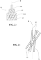
- the inventors behind the invention hypothesize that this ratio makes it possible to obtain relatively large radial passage windows for the elastomer composition within each external strand.
- the radial passage windows are defined as being the intersection between on the one hand the space projected on a plane parallel to the main axis of the cable between two adjacent wires of the outer layer of an external strand and on the other hand the space projected on a plane parallel to the main axis of the cable between two adjacent wires of the intermediate layer of this external strand.
- Such a radial passage window is illustrated on the Figure 24 .
- the cable according to the invention has spaces between the external strands allowing the passage of the elastomer composition.
- the high penetrability of the external strands made possible by the ratio (p3'-p2')/p3' and the desaturation of the external layer of the cable allows the elastomer composition to penetrate on the one hand, between the external strands and, on the other hand, between the external strands and the internal strand.
- this characteristic allows the elastomer composition to infiltrate between the outer layers of the inner and outer strands so as to create a mattress of elastomer composition at least partially absorbing the radial component of the force between the inner strands. and external.
- the direction of winding of the cable opposite the directions of winding of each external layer of each internal and external strand allows better penetrability of the cable, in particular between the external strands.
- the inventors hypothesize that thanks to these winding directions, the external wires of the external strands cross the external wires of the internal strand by forming a relatively point contact zone unlike the cables of the state of the art in which the direction winding direction of the cable is identical to the winding directions of external layers of each internal and external strand and in which the external wires of the external strands cross the external wires of the internal strand forming a less punctual and more linear contact zone, preventing the passage of the elastomer composition to the internal strand .
- each external strand has cylindrical layers.
- the internal strand has cylindrical layers whether this internal strand has two or three layers. It is recalled that such cylindrical layers are obtained when the different layers of a strand are wound at different pitches in pairs and/or when the directions of winding of these layers are distinct from one layer to another.
- a strand with cylindrical layers is very highly penetrable unlike a strand with compact layers in which the pitches of all the layers are equal and the directions of winding of all the layers are identical and has a much lower penetrability.
- the cable is devoid of any polymeric composition, in particular the cable is devoid of any sheath of any polymeric composition covering the internal strand.
- the cable is devoid of any elastomeric composition, in particular the cable is devoid of any sheath of any elastomeric composition covering the internal strand.
- the cable is metallic.
- metallic cable means a cable made up of wires consisting mainly (that is to say for more than 50% of these wires) or entirely (for 100% of the wires) of a metallic material.
- Such a metal cable is preferably implemented with a steel cable, more preferably in pearlitic (or ferrito-pearlitic) carbon steel designated below by "carbon steel”, or even in stainless steel (by definition, steel comprising at least 11% chromium and at least 50% iron). But it is of course possible to use other steels or other alloys.
- its carbon content (% by weight of steel) is preferably between 0.4% and 1.2%, in particular between 0.5% and 1.1%; these contents represent a good compromise between the mechanical properties required for the tire and the feasibility of the wires.
- the metal or steel used can itself be coated with a metallic layer improving, for example, the processing properties of the metal cable and/or its constituent elements, or the usage properties of the cable and/or the tire themselves, such as adhesion properties, corrosion resistance or even resistance to aging.
- the steel used is covered with a layer of brass (Zn-Cu alloy) or zinc.
- the wires of the same layer of a predetermined strand all have substantially the same diameter.
- the external strands all have substantially the same diameter.
- each wire of each strand has a diameter ranging from 0.15 mm to 0.60 mm, preferably from 0.20 mm to 0.50 mm, more preferably from 0.22 mm to 0.40 mm and even more preferably from 0.24 mm to 0.35 mm.
- polymer composition or polymeric composition is meant that the composition comprises at least one polymer.
- a polymer may be a thermoplastic, for example a polyester or a polyamide, a thermosetting polymer, an elastomer, for example natural rubber, a thermoplastic elastomer or a mixture of these polymers.
- elastomer composition or elastomeric composition is meant that the composition comprises at least one elastomer or a rubber (the two terms being synonymous) and at least one other component.
- the elastomer composition also includes a vulcanization system, a filler. More preferably, the elastomer is diene.
- the external strands are wound helically around the internal strand at a pitch ranging from 40 mm to 100 mm and preferably ranging from 50 mm to 90 mm.
- the dimension of the radial passage windows of the elastomer composition is maximum and makes it possible to optimize the penetrability of each external strand.
- the pitch p1' is such that 3 mm ⁇ p1' ⁇ 16 mm, preferably 4 mm ⁇ p1' ⁇ 13 mm and more preferably 5 mm ⁇ p1' ⁇ 10 mm.
- the pitch p2' is such that 8 mm ⁇ p2' ⁇ 20 mm, preferably 9 mm ⁇ p2' ⁇ 18 mm and more preferably 10 mm ⁇ p2' ⁇ 16 mm.
- the pitch p3' is such that 10 mm ⁇ p3' ⁇ 40 mm, preferably 12 mm ⁇ p3' ⁇ 30 mm and more preferably 15 mm ⁇ p3' ⁇ 25 mm.
- Steps p1', p2' and p3' in these preferential ranges make it possible to obtain a cable having mechanical properties compatible with pneumatic use, a cost and a relatively low linear mass of the cable.
- the diameter of a strand is the diameter of the smallest circle within which the strand is circumscribed.
- the internal strand TI has a diameter DI and each external strand TE has a diameter DE.
- DI/DE ⁇ 1.30 preferably DI/DE ⁇ 1.35 and more preferably DI/DE ⁇ 1.40.
- DI/DE ⁇ 1.70 preferably DI/DE ⁇ 1.65 and more preferably DI/DE ⁇ 1.60.
- DI/DE ⁇ 1.60 preferably DI/DE ⁇ 1.65 and more preferably DI/DE ⁇ 1.70.
- DI/DE ⁇ 2.0 preferably DI/DE ⁇ 1.95 and more preferably DI/DE ⁇ 1.90.
- DI/DE ⁇ 2.00 preferably DI/DE ⁇ 2.05 and more preferably DI/DE ⁇ 2.10.
- DI/DE ⁇ 2.50 preferably DI/DE ⁇ 2.45 and more preferably DI/DE ⁇ 2.40.
- the outer layer of the cable is completely unsaturated.
- a completely unsaturated layer of strands is, as opposed to an incompletely unsaturated layer, such that there is sufficient space in this layer to add at least one (X+1) th strand of the same diameter as the X strands of the layer, several strands may then be in contact with each other or not.
- the sum SIE of the interstrand distances E of the outer layer of the cable is such that SIE ⁇ DE.
- the sum SIE is the sum of the interstrand distances E separating each pair of adjacent strands of the layer.
- the inter-strand distance of a layer is defined, on a section of the cable perpendicular to the main axis of the cable, as the shortest distance which separates, on average, two adjacent strands of the layer.
- the interstrand distance E is calculated by dividing the sum SIE by the number of spaces separating the strands of the layer.
- the outer layer of the cable is incompletely unsaturated.
- An incompletely unsaturated layer of strands is such that there is not enough space in this layer to add at least one (X+1) th strand of the same diameter as the X strands of the layer.
- the sum SIE of the interstrand distances E of the outer layer of the cable is such that SIE ⁇ DE.
- each external wire of the internal strand has a diameter d3 greater than or equal to the diameter d3' of each external wire of each external strand, preferably each external wire of the internal strand has a diameter d3 greater than the diameter d3' of each external wire of each external strand.
- each external wire of the internal strand can support the radial component of the force exerted by the external strands on the internal strand during traction of the cable.
- This characteristic d3>d3' makes it possible to restore or even improve the breaking strength of the cable compared to a cable comprising an arch formed by the external strands or compared to a cable in which d3 ⁇ d3'.
- 1 ⁇ d3/d3' ⁇ 2 more preferably 1 ⁇ d3/d3' ⁇ 1.5 and even more preferably 1 ⁇ d3/d3' ⁇ 1.25 or 1.25 ⁇ d3/d3' ⁇ 1, 5.
- M' 7, 8, 9 or 10
- N' 12, 13, 14 or 15.
- the sum SI2' of the interwire distances of the intermediate layer is such that SI2' ⁇ d3' with d3' being the diameter of each external wire of each external strand, preferably SI2' ⁇ 0.8 x d3'.
- the sum SI2' is the sum of the interwire distances separating each pair of adjacent wires of the intermediate layer.
- the interwire distance of a layer is defined, on a section of the cable perpendicular to the main axis of the cable, as the shortest distance which separates, on average, two adjacent wires of the layer.
- the interwire distance is calculated by dividing the sum SI2' by the number of spaces separating the wires of the intermediate layer.
- the diameter d3' of the external wires of the external layer of each external strand being preferentially greater than the sum SI2', the external wires are prevented from penetrating into the intermediate layer. This ensures good architectural stability, which further reduces the risk of modification of the radial passage windows of the elastomer composition and therefore the risk of degrading the good penetrability of each external strand.
- the intermediate layer of each external strand is desaturated.
- a layer of threads desaturated with threads is such that there is sufficient space between the threads so as to allow the passage of an elastomer composition.
- a desaturated layer means that the wires of this layer do not touch each other and that there is enough space between two adjacent wires of the layer allowing the passage of an elastomer composition through the layer.
- a saturated layer of threads is such that there is not sufficient space between the threads of the layer so as to allow the passage of an elastomer composition, for example because the threads of the layer are affect two by two.
- the interwire distance of the intermediate layer of each external strand is greater than or equal to 35 ⁇ m, even more preferably greater than or equal to 50 ⁇ m and very preferably greater than or equal to 60 ⁇ m.
- the desaturation of the intermediate layer of each external strand advantageously makes it possible to facilitate the passage of the elastomer composition to the center of each external strand and therefore to make the external strand less sensitive to corrosion.
- the intermediate layer of each external strand is incompletely unsaturated.
- an incompletely unsaturated layer of wires is such that there is not enough space in this layer to add at least one (X'+1) th wire of the same diameter as the X' wires of the layer.
- the sum SI2' of the interwire distances I2' of the intermediate layer is less than the diameter d2' of the intermediate wires of the intermediate layer.
- the sum SI2' of the interwire distances of the intermediate layer of each external strand is such that SI2' ⁇ d2'.
- the incomplete unsaturation of the intermediate layer of each external strand ensures architectural stability of the intermediate layer. This reduces the risk of an external wire penetrating the intermediate layer, which would modify the radial passage windows of the elastomer composition and therefore degrade the good penetrability of each external strand. Furthermore, the incomplete unsaturation of the intermediate layer of each external strand ensures that each external strand comprises a relatively high number of intermediate wires and therefore has a relatively high breaking force.
- the intermediate layer of each external strand is completely unsaturated.
- a completely unsaturated layer of wires is such that there is enough space in this layer to add at least one (X'+1) th wire of the same diameter as the X' wires of the layer, several wires being able to then be or not in contact with each other.
- the sum SI2' of the interwire distances I2' of the intermediate layer is greater than or equal to the diameter d2' of the intermediate wires of the intermediate layer.
- the sum SI2' of the interwire distances of the intermediate layer of each external strand is such that SI2' ⁇ d2'.
- the outer layer of each outer strand is desaturated, preferably completely unsaturated.
- the desaturation of the external layer of each external strand advantageously makes it possible to facilitate the passage of the elastomer composition into and through each external strand and therefore to make each external strand less sensitive to corrosion. .
- the interwire distance of the outer layer of each outer strand is greater than or equal to 5 ⁇ m.
- the interwire distance of the outer layer of each outer strand is greater than or equal to 15 ⁇ m, more preferably greater than or equal to 35 ⁇ m, even more preferably greater than or equal to 50 ⁇ m and very preferably greater than or equal to 60 ⁇ m.
- a completely unsaturated layer of wires is such that there is enough space in this layer to add at least one (X'+1) th wire of the same diameter as the X' wires of the layer, several wires being able to then be or not in contact with each other.
- external layer of completely unsaturated external strand we mean that the sum SI3' of the interwire distances I3' of the external layer is greater than or equal to the diameter d3' of the external wires of the external layer.
- the sum SI3' of the interwire distances of the outer layer of each outer strand is such that SI3' ⁇ d3'.
- the sum SI3' is the sum of the inter-wire distances separating each pair of adjacent wires of the outer layer.
- the interwire distance of a layer is defined, on a section of the cable perpendicular to the main axis of the cable, as the shortest distance which separates, on average, two adjacent wires of the layer.
- the interwire distance is calculated by dividing the sum SI3' by the number spaces separating the wires from the outer layer.
- each outer strand makes it possible to maximize the penetration of the elastomer composition into each outer strand and therefore to make each outer strand even less sensitive to corrosion.
- each internal wire of each external strand has a diameter d1' greater than or equal to the diameter d2' of each intermediate wire of each external strand and very preferably 1 ⁇ d1'/d2' ⁇ 1.10.
- the use of diameters such as d1'>d2' makes it possible to promote the penetrability of the elastomer composition through the intermediate layer.
- d1'>d2' we very preferably have d1'/d2' ⁇ 1.10 which allows, on the one hand, to control the architectural stability of the intermediate layer and, on the other hand, to make the present invention of 'an even greater interest due to the relatively weak desaturation created by the difference between d1' and d2'.
- each internal wire of each external strand has a diameter d1' greater than or equal to the diameter d3' of each external wire of each external strand and very preferably 1 ⁇ d17d3' ⁇ 1.10.
- the use of diameters such as d1'>d3' makes it possible to promote the penetrability of the elastomer composition through the external layer.
- d1'>d3' we very preferably have d1'/d3' ⁇ 1.10 which allows, on the one hand, to control the architectural stability of the external layer and, on the other hand, to make the present invention of 'an even greater interest due to the relatively weak desaturation created by the difference between d1' and d3'.
- each intermediate wire of each external strand has a diameter d2' equal to the diameter d3' of each external wire of each external strand.
- each external strand is of the type not gummed in situ.
- non-gummed in situ we mean that before assembly of the outer layer of the cable and before assembly of the cable, each outer strand is made up of the wires of the different layers and devoid of polymer composition, in particular elastomer composition.
- the outer layer of the internal strand is desaturated, preferably completely unsaturated.
- the desaturation of the outer layer of the internal strand advantageously facilitates the passage of the elastomer composition to the center of the internal strand and therefore makes the internal strand less sensitive to corrosion.
- the interwire distance of the external layer of the internal strand is greater than or equal to 5 ⁇ m.
- the interwire distance of the outer layer of the internal strand is greater than or equal to 15 ⁇ m, more preferably greater than or equal to 35 ⁇ m, even more preferably greater than or equal to 50 ⁇ m and very preferably greater than or equal to 60 ⁇ m.
- the outer layer of the internal strand is preferably completely unsaturated.
- a completely unsaturated layer of wires is such that there is enough space in this layer to add at least one (X+1) th wire of the same diameter as the or not in contact with each other.
- the sum SI3 of the interwire distances I3 of the external layer is greater than or equal to the diameter d3 of the external wires of the external layer.
- the sum SI3 of the interwire distances of the outer layer of the internal strand is such that SI3 ⁇ d3.
- the sum SI3 is the sum of the inter-wire distances separating each pair of adjacent wires of the external layer.
- the interwire distance of a layer is defined, on a section of the cable perpendicular to the main axis of the cable, as the shortest distance which separates, on average, two adjacent wires of the layer.
- the interwire distance is calculated by dividing the sum SI3 by the number of spaces separating the wires of the outer layer.
- the complete unsaturation of the outer layer of the internal strand makes it possible to maximize the penetration of the elastomer composition into the internal strand and therefore to make the internal strand even less sensitive to corrosion.
- each internal wire of the internal strand has a diameter d1 greater than or equal to the diameter d3 of each external wire of the internal strand and very preferably 1 ⁇ d1/d3 ⁇ 1.10.
- the use of diameters such as d1>d3 makes it possible to promote the penetrability of the elastomer composition through the external layer.
- d1>d3 we very preferably have d1/d3 ⁇ 1.10 which allows, on the one hand, to control the architectural stability of the external layer and, on the other hand, to make the good penetrability of the internal strand of even greater interest due to the relatively low desaturation created by the difference between d1 and d3.
- the internal strand is of the gummed in situ type.
- a strand comprises, before assembling the cable, a layer of a polymer composition, in particular an elastomer composition arranged between at least two layers of radially adjacent wires, optionally between each layer of radially adjacent wires.
- a gummed strand in situ is notably described in WO2010054790 .
- the internal strand is of the type not gummed in situ.
- the internal strand is made up of the wires of the different layers and devoid of polymer composition, in particular elastomer composition.
- the internal strand has two layers.
- the outer layer of the inner strand is wound around the inner layer of the inner strand in contact with the inner layer of the inner strand.
- the internal strand comprises a wire assembly consisting of two layers of wires, neither more nor less, that is, the wire assembly has two layers of wires, not one, not three , but only two.
- Q 1, 2, 3 or 4.
- N 7, 8, 9 or 10
- the intermediate layer of each external strand is wound around the internal layer of each external strand in a winding direction identical to the winding direction of the cable.
- the internal layer of the internal strand is wound helically in a winding direction identical to the winding direction of the cable.
- the internal layer of the internal strand is wound helically in a winding direction opposite to the winding direction of the cable.
- the internal layer of each external strand is wound helically in a winding direction identical to the winding direction of the cable or, alternatively, in a winding direction opposite to the cable winding direction.
- the internal layer of each external strand is wound helically in a winding direction identical to the winding direction of the intermediate layer of each external strand.
- the intermediate layer of each outer strand is wound around the inner layer of each strand external in a direction of winding opposite to the direction of winding of the cable.
- the internal layer of the internal strand is wound helically in a winding direction identical to the winding direction of the cable.
- the internal layer of each external strand is wound helically in a winding direction identical to the winding direction of the cable or, alternatively, in a winding direction opposite to the cable winding direction.
- the internal layer of each external strand is wound helically in a winding direction identical to the winding direction of the intermediate layer of each external strand.
- the outer layer of the inner strand is wrapped around the middle layer of the inner strand in contact with the middle layer of the inner strand and the middle layer of the inner strand is wound around the inner layer of the inner strand in contact of the internal layer of the internal strand.
- the inner strand comprises a wire assembly consisting of three layers of wires, no more and no less, that is, the wire assembly has three layers of wires, not two, not four , but only three.
- Q 1, 2, 3 or 4.
- Q 1.
- the elastomer composition acts as a hooping layer around the internal strand, in particular around the external and intermediate layers of the internal strand preventing the exit of the wire internal even under repeated compressive forces.
- the dimension of the radial passage windows of the elastomer composition is maximum and makes it possible to optimize the penetrability of the internal strand.
- the pitch p1 is such that 3 mm ⁇ p1 ⁇ 16 mm, preferably 4 mm ⁇ p1 ⁇ 13 mm and more preferably 5 mm ⁇ p1 ⁇ 10 mm.
- the pitch p2 is such that 8 mm ⁇ p2 ⁇ 20 mm, preferably 9 mm ⁇ p2 ⁇ 18 mm and more preferably 10 mm ⁇ p2 ⁇ 16 mm.
- the pitch p3 is such that 10 mm ⁇ p3 ⁇ 40 mm, preferably 12 mm ⁇ p3 ⁇ 30 mm and more preferably 15 mm ⁇ p3 ⁇ 25 mm.
- Steps p1, p2 and p3 in these preferential ranges make it possible to obtain a cable having mechanical properties compatible with pneumatic use, a cost and a relatively low linear mass of the cable.
- the sum SI2 of the interwire distances of the intermediate layer is such that SI2 ⁇ d3 with d3 being the diameter of each external wire of the internal strand, preferably SI2 ⁇ 0.8 x d3.
- the diameter d3 of the external wires of the external layer of the internal strand being preferentially greater than the sum SI2, the external wires are prevented from penetrating into the intermediate layer. This ensures good architectural stability, which reduces the risk of modification of the radial passage windows of the elastomer composition and therefore the risk of degrading the good penetrability of the internal strand.
- the sum SI2 is the sum of the inter-wire distances separating each pair of adjacent wires of the intermediate layer.
- the interwire distance of a layer is defined, on a section of the cable perpendicular to the main axis of the cable, as the shortest distance which separates, on average, two adjacent wires of the layer.
- the interwire distance is calculated by dividing the sum SI2 by the number of spaces separating the wires of the intermediate layer.
- the intermediate layer of the internal strand is desaturated.
- the interwire distance of the intermediate layer of the internal strand is greater than or equal to 5 ⁇ m.
- the interwire distance of the intermediate layer of the internal strand is greater than or equal to 15 ⁇ m, more preferably greater than or equal to 35 ⁇ m, even more preferably greater than or equal to 50 ⁇ m and very preferably greater than or equal to 60 ⁇ m.
- the desaturation of the intermediate layer of the internal strand advantageously facilitates the passage of the elastomer composition to the center of the internal strand and therefore makes the internal strand less sensitive to corrosion.
- the intermediate layer of the internal strand is incompletely unsaturated.
- an incompletely unsaturated layer of wires is such that there is not enough space in this layer to add at least one (X+1) th wire of the same diameter as the X wires of the layer.
- the sum SI2 of the interwire distances I2 of the intermediate layer is less than the diameter d2 of the intermediate wires of the intermediate layer.
- the sum SI2 of the interwire distances of the intermediate layer of the internal strand is such that SI2 ⁇ d2.
- the incomplete unsaturation of the intermediate layer of the internal strand ensures architectural stability of the intermediate layer. Furthermore, the incomplete unsaturation of the intermediate layer of the internal strand ensures that the internal strand comprises a relatively high number of intermediate wires and therefore has a relatively high breaking strength.
- the intermediate layer of the internal strand is completely unsaturated.
- a completely unsaturated layer of wires is such that there is enough space in this layer to add at least one (X+1) th wire of the same diameter as the or not in contact with each other.
- the sum SI2 of the interwire distances I2 of the intermediate layer is greater than or equal to the diameter d2 of the intermediate wires of the intermediate layer.
- the sum SI2 of the interwire distances of the intermediate layer of the internal strand is such that SI2 ⁇ d2.
- each internal wire of the internal strand has a diameter d1 greater than or equal to the diameter d2 of each intermediate wire of the internal strand and very preferably 1 ⁇ d1/d2 ⁇ 1.10.
- the use of diameters such as d1>d2 makes it possible to promote the penetrability of the elastomer composition through the intermediate layer.
- d1>d2 we very preferably have d1/d2 ⁇ 1.10 which allows, on the one hand, to control the architectural stability of the intermediate layer and, on the other hand, to make the internal strand of an even greater interest due to the relatively low desaturation created by the difference between d1 and d2.
- each intermediate wire of the internal strand has a diameter d2 equal to the diameter d3 of each external wire of the internal strand.
- the intermediate layer of each external strand is wound around the internal layer of each external strand in a winding direction identical to the winding direction of the cable.
- the intermediate layer of the internal strand is wound around the internal layer of the internal strand in a winding direction identical to the winding direction of the cable.
- the intermediate layer of the internal strand is wound around the internal layer of the internal strand in a direction of winding opposite to the direction of winding of the cable.
- the internal layer of the internal strand is wound helically in a winding direction identical to the winding direction of the cable or, alternatively, in a direction of winding opposite to the direction of winding of the cable.
- the internal layer of the internal strand is wound helically in a direction of winding identical to the direction of winding of the intermediate layer of the internal strand.
- the internal layer of each external strand is wound helically in a winding direction identical to the winding direction of the cable or, alternatively, in a winding direction opposite to the cable winding direction.
- the internal layer of each external strand is wound helically in a winding direction identical to the winding direction of the intermediate layer of each external strand.
- the intermediate layer of each outer strand is wound around the inner layer of each outer strand in a winding direction opposite to the winding direction of the cable.
- the intermediate layer of the internal strand is wound around the internal layer of the internal strand in a winding direction identical to the winding direction of the cable.
- the intermediate layer of the internal strand is wound around the internal layer of the internal strand in a direction of winding opposite to the direction of winding of the cable.
- the friction of the wires of the adjacent layers and therefore their wear is limited.
- the internal layer of the internal strand is wound helically in a winding direction identical to the winding direction of the cable or, alternatively, in a direction of winding opposite to the direction of winding of the cable.
- the internal layer of the internal strand is wound helically in a direction of winding identical to the direction of winding of the intermediate layer of the internal strand.
- the internal layer of each external strand is wound helically in a winding direction identical to the winding direction of the cable or, alternatively, in a winding direction opposite to the cable winding direction.
- the internal layer of each external strand is wound helically in a winding direction identical to the winding direction of the intermediate layer of each external strand.
- Another object of the invention is a tire comprising a cable as defined above.
- the cable is particularly intended for industrial vehicles chosen from heavy vehicles such as "heavy goods vehicles” - i.e., metro, bus, road transport vehicles (trucks, tractors, trailers), off-road vehicles -, agricultural machinery or civil engineering, other transport or handling vehicles.
- heavy vehicles such as "heavy goods vehicles” - i.e., metro, bus, road transport vehicles (trucks, tractors, trailers), off-road vehicles -, agricultural machinery or civil engineering, other transport or handling vehicles.
- Examples of such dimensions are for example 40.00 R 57 or 59/80 R 63.
- the tire comprises a carcass reinforcement anchored in two beads and surmounted radially by a crown reinforcement itself surmounted by a tread, the crown reinforcement being joined to said beads by two sidewalls, carcass reinforcement comprising at least one cable as defined above.
- the tire comprises a carcass reinforcement anchored in two beads and surmounted radially by a crown reinforcement itself surmounted by a tread, the crown reinforcement being joined to said beads by two sidewalls and comprising at least one cable as defined above.
- the carcass reinforcement comprises at least one carcass ply comprising wire carcass metal reinforcement elements, each wire carcass metal reinforcement element making an angle of between 80° and 90° with the circumferential direction of the tire .
- the top frame comprises a working frame comprising at least one cable as defined above.
- the working frame comprises at least one working layer comprising wire working metal reinforcing elements arranged one substantially parallel to the other, each wire working metal reinforcing element making an angle at most equal to 60°, of preferably ranging from 15° to 40° with the circumferential direction of the tire and being formed by a cable as defined above.
- the working frame comprises at least first and second working layers, each first and second working layer comprising respectively first and second wire working metal reinforcing elements arranged one substantially parallel to the other in each first and second working ply, each first and second wire working metal reinforcement element making an angle at most equal to 60°, preferably ranging from 15° to 40° with the circumferential direction of the tire and being formed by a cable as defined above.
- the first and second working metal reinforcing wire elements are crossed from one working ply to the other, that is to say that the orientation of the angle made by the first wire elements of metal reinforcement working with the circumferential direction of the tire is opposite to the orientation of the angle made by the second wire elements of metal reinforcement working with the circumferential direction of the tire.
- the crown reinforcement comprises a protective reinforcement comprising at least one protective sheet comprising wire-shaped protective metal reinforcement elements arranged one substantially parallel to the other, each wire-shaped protective metal reinforcement element making an angle at least equal to each other. at 10°, preferably ranging from 10° to 35° and preferably from 15° to 30° with the circumferential direction of the tire.
- the protective reinforcement comprises first and second protective layers, each first and second protective layers respectively comprising first and second metallic protective reinforcement wire elements arranged one substantially parallel to the other in each first and second protective layer, each first and second wire element of protective metal reinforcement making an angle at least equal to 10°, preferably ranging from 10° to 35° and preferably from 15° to 30° with the circumferential direction of the pneumatic.
- the protective frame is radially interposed between the tread and the working frame.
- the crown reinforcement comprises an additional reinforcement comprising at least one additional sheet comprising additional wire-shaped metal reinforcing elements arranged one substantially parallel to the other in the additional sheet, each additional wire-shaped metal reinforcement element making an angle at most equal at 10°, preferably ranging from 5° to 10° with the circumferential direction of the tire.
- the additional reinforcement comprises first and second additional layers, each first and second additional layers respectively comprising first and second additional metal reinforcing wire elements arranged one substantially parallel to the other in each first and second layer additional, each first and second additional metallic reinforcement wire element making an angle at most equal to 10°, preferably ranging from 5° to 10° with the circumferential direction of the tire.
- any interval of values designated by the expression “between a and b” represents the range of values going from more than a to less than b (that is to say limits a and b excluded) while any interval of values designated by the expression “from a to b” means the range of values going from terminal “a” to terminal “b”, that is to say including the strict limits “a” and “b”.
- a reference mark X, Y, Z is shown corresponding to the usual respectively axial (X), radial (Y) and circumferential (Z) orientations of a tire.
- the “median circumferential plane” M of the tire is the plane which is normal to the axis of rotation of the tire and which is located equidistant from the annular reinforcement structures of each bead and passes through the middle of the crown reinforcement.
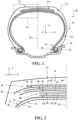
- the tire 10 is for heavy civil engineering type vehicles, for example of the “dumper” type.
- the tire 10 has a dimension of type 53/80R63.
- the tire 10 comprises a crown 12 reinforced by a crown reinforcement 14, two sidewalls 16 and two beads 18, each of these beads 18 being reinforced with an annular structure, here a rod 20.
- the crown reinforcement 14 is surmounted radially by a tread 22 and joined to the beads 18 by the sides 16.
- a carcass reinforcement 24 is anchored in the two beads 18, and is here wound around the two rods 20 and comprises a turnaround 26 disposed towards the outside of the tire 20 which is here shown mounted on a rim 28.
- the carcass reinforcement 24 is surmounted radially by the crown reinforcement 14.
- the carcass reinforcement 24 comprises at least one carcass ply 30 comprising metallic carcass reinforcement wire elements 31 and extending from one bead 18 to the other so as to make an angle of between 80° and 90° with the circumferential direction Z of the tire 10.
- the tire 10 also comprises a sealing ply 32 made of an elastomer (commonly called inner rubber) which defines the radially internal face 34 of the tire 10 and which is intended to protect the carcass ply 30 from the diffusion of air coming from of the interior space of the tire 10.
- a sealing ply 32 made of an elastomer (commonly called inner rubber) which defines the radially internal face 34 of the tire 10 and which is intended to protect the carcass ply 30 from the diffusion of air coming from of the interior space of the tire 10.
- the crown reinforcement 14 comprises, radially from the outside towards the inside of the tire 10, a protective reinforcement 36 arranged radially inside the tread 22, a working reinforcement 38 arranged radially inside of the protective frame 36 and an additional frame 80 arranged radially inside the working frame 38.
- the protective frame 36 is thus radially interposed between the tread 22 and the working frame 38.
- the working frame 38 is radially interposed between the protective frame 36 and the additional frame 80.
- the protective frame 36 comprises first and second protective layers 42, 44, the first layer 42 being arranged radially inside the second layer 44.
- Each first and second protective layers 42, 44 respectively comprise first and second wire elements of protective metal reinforcement 43, 45 arranged one substantially parallel to the other in each first and second protective layer 42, 44.
- Each first and second wire element of protective metal reinforcement 43, 45 makes an angle at least equal at 10°, preferably ranging from 10° to 35° and preferably from 15° to 30° with the circumferential direction Z of the tire.
- the working frame 38 comprises first and second working layers 46, 48, the first layer 46 being arranged radially inside the second layer 48.
- Each first and second working layer 46, 48 respectively comprises first and second wire working metal reinforcement elements 47, 49 arranged one substantially parallel to the other in each first and second working ply 46, 48.
- Each first and second wire working metal reinforcement element 47, 49 makes an angle at most equal at 60°, preferably ranging from 15° to 40° with the circumferential direction Z of the tire 10.
- first and second wire reinforcement elements working metal elements 47, 49 are crossed from one working ply to another, that is to say that the orientation of the angle made by the first wire working metal reinforcing elements 47 with the circumferential direction Z of the tire 10 is opposite the orientation of the angle made by the second wire working metal reinforcement elements 49 with the circumferential direction Z of the tire 10.
- the additional reinforcement 80 also called a limiter block, whose function is to partially take up the mechanical inflation stresses, comprises first and second additional layers 82, 84, each first and second additional layers 82, 84 respectively comprising first and second additional metallic reinforcing wire elements 83, 85 arranged one substantially parallel to the other in each first and second additional layer 82, 84.
- Each first and second additional metallic reinforcing wire element 83, 85 makes an angle at most equal to 10° , preferably ranging from 5° to 10° with the circumferential direction Z of the tire 10.
- the additional metallic reinforcing wire elements are for example as described in FR 2 419 181 Or FR 2 419 182 .
- each first and second wire working metal reinforcement element 47, 49 is formed by a cable according to the invention, for example the cable 50 described below.
- each wire frame metal reinforcement element 31 formed by a cable according to the invention for example the cable 50 described below.
- each first and second working metal reinforcement wire element 47, 49 and each carcass metal reinforcement wire element 31 is formed by a cable according to the invention, these cables being able to be identical or different depending on whether they are wire elements of metallic reinforcement 31, 47 or 49.
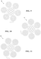
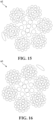
- the cable 50 is metallic and is of the multi-strand type with two cylindrical layers. Thus, we understand that the layers of strands constituting the cable 50 are two in number, no more, no less. The layers of strands are adjacent and concentric.
- the cable 50 is devoid of polymeric composition and elastomer composition when it is not integrated into the tire.
- the cable 50 comprises an internal layer CI of the cable 50 as well as a layer external CE of the cable 50.
- the internal layer CI consists of a single internal strand TI.
- the cable 50 also includes a hoop F consisting of a single hoop wire.
- the internal TI strand has an infinite pitch.
- the outer layer CE is wound around the inner layer CI in a winding direction of the cable, here the direction S.
- the outer strands TE are wound helically around the inner strand TI at a pitch p such that 40 mm ⁇ p ⁇ 100 mm and preferably 50 mm ⁇ p ⁇ 90 mm.
- p 70 mm.
- the hoop F is wound around the outer layer CE in a direction of winding of the hoop, here opposite to the direction of winding of the cable, in this case in the direction Z.
- the hoop wire is wound helically around the external TE strands with a pitch pf such as 2 mm ⁇ pf ⁇ 10 mm and preferably 3 mm ⁇ pf ⁇ 8 mm.
- pf 5.1 mm.
- the assembly constituted by the internal layers CI and external CE, that is to say the cable 50 without the hoop F, has a diameter D greater than or equal to 4 mm and less than or equal to 6 mm, preferably 5 .5 mm and more preferably 5.0 mm.
- D is 4.90 mm.
- the outer CE layer of cable 50 is desaturated.
- the average inter-strand distance E separating two adjacent external strands TE is greater than or equal to 30 ⁇ m, preferably greater than or equal to 70 ⁇ m, more preferably greater than or equal to 100 ⁇ m, even more preferably greater than or equal to 150 ⁇ m and very preferably greater than or equal to 200 ⁇ m.
- the inter-strand distance of the outer layer of outer strands is greater than or equal to 70 ⁇ m.
- E 98 ⁇ m.
- the internal strand TI has a diameter DI and each external strand TE has a diameter DE such that the ratio DI/DE>1, preferably DI/DE ⁇ 1.05 and more preferably DI/DE ⁇ 1.10.
- the TI internal strand has at least two layers.
- the internal strand TI is three-layered.
- the internal TI strand includes, here is made up of, three layers, no more, no less.
- the internal strand TI comprises an internal layer C1 made up of Q internal wire(s) F1, an intermediate layer C2 made up of M intermediate wires F2 wound helically around the internal layer C1 and an external layer C3 made up of N wires external F3 wound helically around the internal layer C1 and around and in contact with the intermediate layer C2.
- the internal wire F1 has an infinite pitch.
- the intermediate layer C2 of the internal strand TI is wound around the internal layer C1 of the internal strand TI in a direction of winding of the intermediate layer of the internal strand, here in the direction Z, opposite to the direction of winding of the cable S.
- M intermediate wires F2 are wound helically around the internal wire F1 at a pitch p2 such that 8 mm ⁇ p2 ⁇ 20 mm, preferably 9 mm ⁇ p2 ⁇ 18 mm and more preferably 10 mm ⁇ p2 ⁇ 16 mm.
- p2 14 mm.
- the outer layer C3 of the inner strand TI is wound around the inner C1 and intermediate layers C2 of the inner strand TI in a direction of winding of the outer layer of the inner strand, here in the direction Z, opposite to the direction of winding of the cable S and in the same direction Z as the intermediate layer C2 of the internal strand TI.
- the N external wires F3 are wound helically around the M intermediate wires F2 at a pitch p3 such that 10 mm ⁇ p3 ⁇ 40 mm, preferably 12 mm ⁇ p3 ⁇ 30 mm, more preferably 15 mm ⁇ p3 ⁇ 25 mm.
- p3 20 mm.
- the internal strand has cylindrical layers.
- the intermediate layer C2 of the internal strand TI is desaturated and incompletely unsaturated.
- the interwire distance I2 of the intermediate layer C2 separating on average the M intermediate wires is advantageously greater than or equal to 5 ⁇ m and here equal to 11.6 ⁇ m.
- the intermediate layer C2 being incompletely unsaturated, the sum SI2 of the interwire distances I2 of the intermediate layer C2 is less than the diameter d2 of the intermediate wires F2 of the intermediate layer C2.
- the sum SI2 of the interwire distances I2 of the intermediate layer C2 is less than the diameter d3 of the external wires F3 of the external layer C3 and preferably less than or equal to 0.8 x d3.
- the outer layer C3 of the inner strand TI is desaturated and completely unsaturated.
- the interwire distance I3 of the external layer C3 separating on average the N external wires is advantageously greater than or equal to 5 ⁇ m, preferably greater than or equal to 15 ⁇ m, more preferably greater than or equal to 35 ⁇ m and here equal to 45 ⁇ m.
- the sum SI3 of the interwire distances I3 of the external layer C3 is greater than the diameter d3 of the external wires F3 of the external layer C3.
- Each internal, intermediate and external wire of the internal strand TI has a diameter d1, d2 and d3 respectively.
- Each diameter of the internal d1, intermediate d2 and external d3 wires of the internal strand TI ranges from 0.15 mm to 0.60 mm, preferably from 0.20 mm to 0.50 mm, more preferably from 0.22 mm to 0 .40 mm and even more preferably from 0.24 mm to 0.35 mm.
- the internal wire F1 of the internal strand TI has a diameter d1 greater than or equal to the diameter d2 of each intermediate wire F2 of the internal strand TI and very preferably 1 ⁇ d1/d2 ⁇ 1.10.
- the internal wire F1 of the internal strand TI has a diameter d1 greater than or equal to the diameter d3 of each external wire F3 of the internal strand TI and very preferably 1 ⁇ d1/d3 ⁇ 1.10.
- each TE outer strand is three-layered.
- each external TE strand includes, here is made up of, three layers, no more, no less.
- the internal layer C1' of each external strand TE is wound helically in a direction of winding of the internal layer of each external strand, here in the direction Z, opposite to the direction of winding S of the cable.
- the Q' internal wires F1' are wound helically at a pitch p1' such that 3 mm ⁇ p1' ⁇ 16 mm, preferably 4 mm ⁇ p1' ⁇ 13 mm and more preferably 5 mm ⁇ p1' ⁇ 10 mm.
- p1' 6 mm.
- the intermediate layer C2' of each external strand TE is wound around the internal layer C1' of each external strand TE in a direction of winding of the intermediate layer of each external strand, here in the direction Z, opposite to the direction of winding S of the cable.
- the M' intermediate wires F2' are wound helically around the internal wires F1' at a pitch p2' such that 8 mm ⁇ p2' ⁇ 20 mm, preferably 9 mm ⁇ p2' ⁇ 18 mm and more preferably 10 mm ⁇ p2 ' ⁇ 16mm.
- p2' 11 mm.
- the outer layer C3' of each outer strand TE is wound around the intermediate layer C2' of each outer strand TE in a winding direction of the outer layer of each outer strand, here in the Z direction, opposite to the winding direction S of the cable and in the same direction Z as the internal C1' and intermediate C2' layers of each external strand TE and in the same direction Z as the external layer C3 of the internal strand TI.
- the N' external wires F3' are wound helically around the M' intermediate wires F2' at a pitch p3' such that 10 mm ⁇ p3' ⁇ 40 mm, preferably 12 mm ⁇ p3' ⁇ 30 mm, more preferably 15 mm ⁇ p3' ⁇ 25 mm.
- p3' 18 mm.
- Steps p2' and p3' verify 0.36 ⁇ (p3'-p2')/p3' ⁇ 0.45.
- each outer strand has cylindrical layers.
- the intermediate layer C2' of each external strand TE is desaturated and here completely unsaturated.
- the interwire distance I2' of the intermediate layer C2' separating on average the M' intermediate wires is advantageously greater than or equal to 5 ⁇ m, preferably greater than or equal to 15 ⁇ m, more preferably greater than or equal to 35 ⁇ m and even more preferably 50 ⁇ m and in this embodiment, the interwire distance I2' is very preferably greater than or equal to 60 ⁇ m and here equal to 75 ⁇ m.
- the sum SI2' of the interwire distances I2' of the intermediate layer C2' is less than the diameter d2' of the intermediate wires F2' of the intermediate layer C2'.
- the outer layer C3' of each outer strand TE is desaturated and completely unsaturated.
- the interwire distance I3' of the external layer C3' separating on average the N' external wires is advantageously greater than or equal to 5 ⁇ m, preferably greater than or equal to 15 ⁇ m, more preferably greater than or equal to 35 ⁇ m and even more preferably 50 ⁇ m and in this embodiment, the interwire distance I2' is very preferably greater than or equal to 60 ⁇ m and here equal to 71 ⁇ m.
- the sum SI3' of the interwire distances I3' of the external layer C3' is greater than the diameter d3' of the external wires F3' of the external layer C3'.
- Each internal, intermediate and external wire of each external TE strand has a diameter d1', d2' and d3' respectively.
- Each diameter of the internal d1', intermediate d2' and external d3' wires of each external strand TE ranges from 0.15 mm to 0.60 mm, preferably from 0.20 mm to 0.50 mm, more preferably from 0. 22 mm to 0.40 mm and even more preferably from 0.24 mm to 0.35 mm.
- the internal wire F1' of each external strand TE has a diameter d1' greater than or equal to the diameter d2' of each intermediate wire F2' of each external strand TE and very preferably 1 ⁇ d1'/d2' ⁇ 1.10.
- the internal wire F1' of each external strand TE has a diameter d1' greater than or equal to the diameter d3' of each external wire F3' of each external strand TE and very preferably 1 ⁇ d1'/d3' ⁇ 1.10.
- Each external wire F3 of the internal strand TI has a diameter d3 greater than or equal to the diameter d3' of each external wire F3 of each external strand TE.
- Each wire has a breaking strength, noted Rm, such that 2500 ⁇ Rm ⁇ 3100 MPa.
- the steel of these wires is said to be SHT (“Super High Tensile”) grade.
- Other yarns can be used, for example yarns of a lower grade, for example of grade NT (“Normal Tensile”) or HT (“High Tensile”), as well as yarns of a higher grade, for example of grade UT (“ Ultra Tensile”) or MT (“Mega Tensile”).
- the cable according to the invention is manufactured using a process comprising steps well known to those skilled in the art.
- torque balancing we mean here in a manner well known to those skilled in the art the cancellation of the residual torques (or the elastic return of torsion) exerted on each wire of the strand, in the intermediate layer as in the outer layer.
- each strand is wound on one or more receiving reels, for storage, before the subsequent operation of assembling the elementary strands by wiring to obtain the multi-strand cable.
- the cable is then incorporated by calendering into composite fabrics formed from a known composition based on natural rubber and carbon black as a reinforcing filler, conventionally used for the manufacture of crown reinforcements of radial tires.
- This composition essentially comprises, in addition to the elastomer and the reinforcing filler (carbon black), an antioxidant, stearic acid, an extension oil, cobalt naphthenate as an adhesion promoter, finally a vulcanization system (sulfur, accelerator, ZnO).
- the composite fabrics reinforced by these cables comprise a matrix of elastomeric composition formed of two thin layers of elastomeric composition which are superimposed on either side of the cables and which respectively have a thickness of between 1 and 4 mm inclusive.
- the calendering pitch (no laying of the cables in the elastomeric composition fabric) ranges from 4 mm to 8 mm.
- Such a permeability test is well known to those skilled in the art and makes it possible to determine the longitudinal air permeability of the cables tested, by measuring the volume of air passing through a test piece under constant pressure for a given time.
- the principle of such a test is to demonstrate the effectiveness of treating a cable to make it airtight; it was described for example in standard ASTM D2692-98.
- Such a test is carried out on cables from manufacturing and not aged.
- the raw cables are previously coated from the outside with an elastomeric composition called coating.
- coating an elastomeric composition
- a series of 10 cables arranged in parallel (inter-cable distance: 20 mm) is placed between two layers or “skims" (two rectangles of 80 x 200 mm) of a diene elastomeric composition in the raw state.
- each skim having a thickness of 5 mm; the whole is then blocked in a mold, each of the cables being maintained under sufficient tension (for example 3 daN) to guarantee its straightness when placed in the mold, using clamping modules; then vulcanization (cooking) is carried out for approximately 10 to 12 hours at a temperature of approximately 120°C and under a pressure of 15 bar (rectangular piston of 80 x 200 mm). After which, the assembly is unmolded and 10 test pieces of cables coated in this way are cut, in the form of parallelepipeds measuring 7x7x60 mm, for characterization.
- sufficient tension for example 3 daN
- vulcanization cooking
- elastomeric coating composition a composition of conventional diene elastomer(s) for tires is used, based on natural rubber (peptized) and carbon black N330 (65 phr), further comprising the following usual additives : sulfur (7 pce), sulfenamide accelerator (1 pce), ZnO (8 pce), stearic acid (0.7 pce), antioxidant (1.5 pce), cobalt naphthenate (1.5 pce) (pce meaning parts by weight per hundred parts of elastomer); the modulus E10 of the elastomeric coating composition is approximately 10 MPa.
- the test is carried out on a 6 cm length of cable, therefore coated with its surrounding elastomeric composition (or elastomeric coating composition) in the cooked state, in the following way: air is sent to the entrance of the cable , under a pressure of 1 bar, and the volume of air at the outlet is measured, using a flow meter (calibrated for example from 0 to 500 cm 3 /min). During the measurement, the cable sample is clamped in a compressed airtight seal (e.g.
- a dense foam or rubber seal such that only the amount of air passing through the cable from one end to the other, along its longitudinal axis, is taken into account by the measurement; the tightness of the waterproof seal itself is checked beforehand using a test piece of solid elastomeric composition, that is to say without cable.
- the average air flow measured (average over the 10 test specimens) is all the lower as the longitudinal impermeability of the cable is high.
- the measurement being made with an accuracy of ⁇ 0.2 cm3/min, measured values less than or equal to 0.2 cm3/min are considered zero; they correspond to a cable which can be described as airtight (totally airtight) along its axis (i.e., in its longitudinal direction).
- the capacity of a strand to be penetrable by an elastomeric composition was determined by simulating the size of the radial passage windows formed by two adjacent wires F2' of the intermediate layer C2' and by two adjacent wires F3 'of the outer layer C3'. Such windows are illustrated on the Figure 23 on which there is shown a schematic view of an external strand along its main axis P and on the Figure 24 which represents the radial passage window S defined previously.
- Such an indicator of strand penetrability is an image of the airtightness of the strand. Indeed, the larger the size of the windows, the higher the penetrability indicator, the more likely the elastomer composition is to penetrate into the strand and the more airtight the strand is.
- the permeability could also be determined by the permeability test described above applied to the strand. However, for the purposes of speed for the evaluation of the strands, the inventors favored the simulation and calculation of the S windows compared to the permeability test.
- Table 6 below shows the results of the permeability test and the penetrability indicator test for three control cables T1, T2 and T3.
- a result greater than 100 in one or other of these tests means that the cable or strand tested has greater impermeability or penetrability than the control cable or strand, here the T1 cable or the strands of the T1 cable.
- the T3 cable has a waterproofness more than twice that of the control cable T1 and this, only because of the ratio (p3'-p2')/p3' of the intermediate layers C2' and outer layers C3' of the outer strands YOU.
- Each table 50.1 to 52.6 corresponds respectively to a pitch p3' equal to 12, 14, 16, 18, 20 and 23 mm.
- the value of the penetrability indicator is significantly greater than that obtained for the corresponding control strand.
- the value of the penetrability indicator is significantly greater than that obtained for the corresponding control strand.
- DI/DE ⁇ 1.30 preferably DI/DE ⁇ 1.35 and more preferably DI/DE ⁇ 1.40 and DI/DE ⁇ 1.70, preferably DI/DE ⁇ 1.65 and more preferably DI/DE ⁇ 1.60.
- DI/DE ⁇ 1.60 preferably DI/DE ⁇ 1.65 and more preferably DI/DE ⁇ 1.70 and DI/ DE ⁇ 2.0, preferably DI/DE ⁇ 1.95 and more preferably DI/DE ⁇ 1.90.
- DI/DE ⁇ 2.00 preferably DI/DE ⁇ 2.05 and more preferably DI/DE ⁇ 2.10 and DI/DE ⁇ 2.50, preferably DI/DE ⁇ 2.45 and more preferably DI/DE ⁇ 2.40.
- the intermediate layer of each external strand is wound around the internal layer of each external strand in a direction of winding identical to the direction of winding of the cable.
- the internal layer of the internal strand is wound helically in a winding direction identical to the winding direction of the cable.
- the internal layer of the internal strand is wound helically in a winding direction opposite to the winding direction of the cable.
- the intermediate layer of each external strand is wound around the internal layer of each strand external in a direction of winding opposite to the direction of winding of the cable.
- the internal layer of the internal strand is wound helically in a winding direction identical to the winding direction of the cable.
- winding directions of the embodiments and alternatives considered above can be either S or Z.
Landscapes
- Engineering & Computer Science (AREA)
- Mechanical Engineering (AREA)
- Ropes Or Cables (AREA)
- Tires In General (AREA)
Applications Claiming Priority (2)
| Application Number | Priority Date | Filing Date | Title |
|---|---|---|---|
| FR1855458 | 2018-06-20 | ||
| PCT/FR2019/051313 WO2019243691A1 (fr) | 2018-06-20 | 2019-06-04 | Câble multi-torons à deux couches à pénétrabilité améliorée |
Publications (2)
| Publication Number | Publication Date |
|---|---|
| EP3810846A1 EP3810846A1 (fr) | 2021-04-28 |
| EP3810846B1 true EP3810846B1 (fr) | 2024-05-22 |
Family
ID=63407442
Family Applications (1)
| Application Number | Title | Priority Date | Filing Date |
|---|---|---|---|
| EP19742437.7A Active EP3810846B1 (fr) | 2018-06-20 | 2019-06-04 | Câble multi-torons à deux couches à pénétrabilité améliorée |
Country Status (5)
| Country | Link |
|---|---|
| EP (1) | EP3810846B1 (https=) |
| JP (1) | JP7345510B2 (https=) |
| AU (1) | AU2019291194B2 (https=) |
| CA (1) | CA3102045A1 (https=) |
| WO (1) | WO2019243691A1 (https=) |
Families Citing this family (4)
| Publication number | Priority date | Publication date | Assignee | Title |
|---|---|---|---|---|
| FR3111924B1 (fr) * | 2020-06-24 | 2022-06-17 | Michelin & Cie | Câble multi-torons à deux couches à endurance sous flexion améliorée |
| FR3111923B1 (fr) * | 2020-06-24 | 2022-06-17 | Michelin & Cie | Câble multi-torons à deux couches à endurance sous flexion améliorée |
| FR3115799B1 (fr) * | 2020-11-05 | 2022-10-14 | Michelin & Cie | Câble multi-torons à deux couches avec couche interne gainée à pénétrabilité améliorée |
| FR3122676B1 (fr) * | 2021-05-07 | 2024-07-12 | Michelin & Cie | Câble multi-torons à deux couches à énergie de rupture surfacique améliorée |
Citations (1)
| Publication number | Priority date | Publication date | Assignee | Title |
|---|---|---|---|---|
| WO2014090996A2 (fr) * | 2012-12-14 | 2014-06-19 | Compagnie Generale Des Etablissements Michelin | Câble métallique à couches à haute pénétrabilité |
Family Cites Families (13)
| Publication number | Priority date | Publication date | Assignee | Title |
|---|---|---|---|---|
| FR2419181A1 (fr) | 1978-03-10 | 1979-10-05 | Michelin & Cie | Perfectionnements aux pneumatiques a carcasse radiale |
| FR2419182A1 (fr) | 1978-03-10 | 1979-10-05 | Michelin & Cie | Pneumatique a carcasse radiale, notamment pour engins de genie civil |
| JP4628166B2 (ja) * | 2005-04-14 | 2011-02-09 | 株式会社ブリヂストン | ゴム補強用スチールコード及び空気入りラジアルタイヤ |
| JP5083943B2 (ja) * | 2007-04-03 | 2012-11-28 | 株式会社ブリヂストン | ゴム物品補強用スチールコードおよびそれを用いた空気入りタイヤ |
| JP2009024268A (ja) * | 2007-07-17 | 2009-02-05 | Bridgestone Corp | ゴム物品補強用コードおよび空気入りタイヤ |
| WO2009048054A1 (ja) | 2007-10-11 | 2009-04-16 | Bridgestone Corporation | ゴム物品補強用スチールコードおよびそれを用いた空気入りタイヤ |
| FR2938557B1 (fr) | 2008-11-17 | 2011-02-18 | Michelin Soc Tech | Cable a trois couches, gomme in situ, pour armature de carcasse de pneumatique |
| FR2947576B1 (fr) * | 2009-07-03 | 2011-08-19 | Michelin Soc Tech | Cable metallique a trois couches gomme in situ de construction 2+m+n |
| WO2011064065A1 (en) | 2009-11-27 | 2011-06-03 | Nv Bekaert Sa | Open muliti-strand cord |
| FR3020016B1 (fr) * | 2014-04-22 | 2016-04-01 | Michelin & Cie | Pneumatique pour vehicule industriel lourd |
| FR3017885A1 (fr) | 2015-06-16 | 2015-08-28 | Michelin & Cie | Cable metallique multi-torons |
| FR3060616A1 (fr) * | 2016-12-20 | 2018-06-22 | Compagnie Generale Des Etablissements Michelin | Cable multi-torons a deux couches a penetrabilite amelioree |
| FR3060617A1 (fr) * | 2016-12-20 | 2018-06-22 | Compagnie Generale Des Etablissements Michelin | Cable multi-torons a deux couches a penetrabilite amelioree |
-
2019
- 2019-06-04 JP JP2020570971A patent/JP7345510B2/ja active Active
- 2019-06-04 CA CA3102045A patent/CA3102045A1/fr active Pending
- 2019-06-04 EP EP19742437.7A patent/EP3810846B1/fr active Active
- 2019-06-04 AU AU2019291194A patent/AU2019291194B2/en active Active
- 2019-06-04 WO PCT/FR2019/051313 patent/WO2019243691A1/fr not_active Ceased
Patent Citations (1)
| Publication number | Priority date | Publication date | Assignee | Title |
|---|---|---|---|---|
| WO2014090996A2 (fr) * | 2012-12-14 | 2014-06-19 | Compagnie Generale Des Etablissements Michelin | Câble métallique à couches à haute pénétrabilité |
Also Published As
| Publication number | Publication date |
|---|---|
| WO2019243691A1 (fr) | 2019-12-26 |
| AU2019291194B2 (en) | 2025-05-22 |
| JP7345510B2 (ja) | 2023-09-15 |
| EP3810846A1 (fr) | 2021-04-28 |
| JP2021528578A (ja) | 2021-10-21 |
| CA3102045A1 (fr) | 2019-12-26 |
| AU2019291194A1 (en) | 2021-01-21 |
Similar Documents
| Publication | Publication Date | Title |
|---|---|---|
| EP3559337B1 (fr) | Câble multi-torons à deux couches à pénétrabilité améliorée | |
| EP3559338B1 (fr) | Câble multi-torons à deux couches à pénétrabilité améliorée | |
| FR3081489A1 (fr) | Dispositif de poignee d’ouvrant, notamment pour vehicule | |
| EP3728729B1 (fr) | Câbles multi-torons à deux couches à très bas, bas et moyen modules | |
| EP3810846B1 (fr) | Câble multi-torons à deux couches à pénétrabilité améliorée | |
| FR2999614A1 (fr) | Cable metallique a couches a haute penetrabilite | |
| WO2015090920A1 (fr) | Câble métallique multi-torons à deux couches | |
| WO2015090921A1 (fr) | Câble métallique multi-torons à deux couches | |
| EP3810851B1 (fr) | Câble multi-torons à deux couches à pénétrabilité améliorée | |
| EP3810848B1 (fr) | Câble multi-torons à deux couches à pénétrabilité améliorée | |
| EP3810847B1 (fr) | Câble multi-torons à deux couches à pénétrabilité améliorée | |
| EP3810850B1 (fr) | Câble multi-torons à deux couches à pénétrabilité améliorée | |
| EP3810849B1 (fr) | Câble multi-torons à deux couches à pénétrabilité améliorée | |
| EP4240897B1 (fr) | Câble multi-torons à deux couches avec couche interne gainée à pénétrabilité améliorée | |
| EP4058627B1 (fr) | Câble multi-torons à deux couches avec couche interne gainée à pénétrabilité améliorée | |
| EP4540456B1 (fr) | Câble multi-torons à deux couches de multi-torons | |
| EP4540455B1 (fr) | Câble multi-torons à deux couches de multi-torons | |
| EP4540458B1 (fr) | Câble multi-torons à une couche de multi-torons | |
| EP4058628B1 (fr) | Câble multi-torons à deux couches avec couche interne gainée à rendement amélioré | |
| WO2014090999A2 (fr) | Câble métallique à couches cylindriques de structure 3+9+14 |
Legal Events
| Date | Code | Title | Description |
|---|---|---|---|
| STAA | Information on the status of an ep patent application or granted ep patent |
Free format text: STATUS: UNKNOWN |
|
| STAA | Information on the status of an ep patent application or granted ep patent |
Free format text: STATUS: THE INTERNATIONAL PUBLICATION HAS BEEN MADE |
|
| PUAI | Public reference made under article 153(3) epc to a published international application that has entered the european phase |
Free format text: ORIGINAL CODE: 0009012 |
|
| STAA | Information on the status of an ep patent application or granted ep patent |
Free format text: STATUS: REQUEST FOR EXAMINATION WAS MADE |
|
| 17P | Request for examination filed |
Effective date: 20210120 |
|
| AK | Designated contracting states |
Kind code of ref document: A1 Designated state(s): AL AT BE BG CH CY CZ DE DK EE ES FI FR GB GR HR HU IE IS IT LI LT LU LV MC MK MT NL NO PL PT RO RS SE SI SK SM TR |
|
| AX | Request for extension of the european patent |
Extension state: BA ME |
|
| DAV | Request for validation of the european patent (deleted) | ||
| DAX | Request for extension of the european patent (deleted) | ||
| STAA | Information on the status of an ep patent application or granted ep patent |
Free format text: STATUS: EXAMINATION IS IN PROGRESS |
|
| 17Q | First examination report despatched |
Effective date: 20230125 |
|
| GRAP | Despatch of communication of intention to grant a patent |
Free format text: ORIGINAL CODE: EPIDOSNIGR1 |
|
| STAA | Information on the status of an ep patent application or granted ep patent |
Free format text: STATUS: GRANT OF PATENT IS INTENDED |
|
| INTG | Intention to grant announced |
Effective date: 20240202 |
|
| GRAS | Grant fee paid |
Free format text: ORIGINAL CODE: EPIDOSNIGR3 |
|
| GRAA | (expected) grant |
Free format text: ORIGINAL CODE: 0009210 |
|
| STAA | Information on the status of an ep patent application or granted ep patent |
Free format text: STATUS: THE PATENT HAS BEEN GRANTED |
|
| AK | Designated contracting states |
Kind code of ref document: B1 Designated state(s): AL AT BE BG CH CY CZ DE DK EE ES FI FR GB GR HR HU IE IS IT LI LT LU LV MC MK MT NL NO PL PT RO RS SE SI SK SM TR |
|
| REG | Reference to a national code |
Ref country code: GB Ref legal event code: FG4D Free format text: NOT ENGLISH |
|
| REG | Reference to a national code |
Ref country code: CH Ref legal event code: EP |
|
| REG | Reference to a national code |
Ref country code: DE Ref legal event code: R096 Ref document number: 602019052588 Country of ref document: DE |
|
| REG | Reference to a national code |
Ref country code: IE Ref legal event code: FG4D Free format text: LANGUAGE OF EP DOCUMENT: FRENCH |
|
| REG | Reference to a national code |
Ref country code: LT Ref legal event code: MG9D |
|
| REG | Reference to a national code |
Ref country code: NL Ref legal event code: MP Effective date: 20240522 |
|
| PG25 | Lapsed in a contracting state [announced via postgrant information from national office to epo] |
Ref country code: IS Free format text: LAPSE BECAUSE OF FAILURE TO SUBMIT A TRANSLATION OF THE DESCRIPTION OR TO PAY THE FEE WITHIN THE PRESCRIBED TIME-LIMIT Effective date: 20240922 |
|
| PG25 | Lapsed in a contracting state [announced via postgrant information from national office to epo] |
Ref country code: BG Free format text: LAPSE BECAUSE OF FAILURE TO SUBMIT A TRANSLATION OF THE DESCRIPTION OR TO PAY THE FEE WITHIN THE PRESCRIBED TIME-LIMIT Effective date: 20240522 |
|
| PG25 | Lapsed in a contracting state [announced via postgrant information from national office to epo] |
Ref country code: FI Free format text: LAPSE BECAUSE OF FAILURE TO SUBMIT A TRANSLATION OF THE DESCRIPTION OR TO PAY THE FEE WITHIN THE PRESCRIBED TIME-LIMIT Effective date: 20240522 Ref country code: HR Free format text: LAPSE BECAUSE OF FAILURE TO SUBMIT A TRANSLATION OF THE DESCRIPTION OR TO PAY THE FEE WITHIN THE PRESCRIBED TIME-LIMIT Effective date: 20240522 |
|
| PG25 | Lapsed in a contracting state [announced via postgrant information from national office to epo] |
Ref country code: GR Free format text: LAPSE BECAUSE OF FAILURE TO SUBMIT A TRANSLATION OF THE DESCRIPTION OR TO PAY THE FEE WITHIN THE PRESCRIBED TIME-LIMIT Effective date: 20240823 |
|
| PG25 | Lapsed in a contracting state [announced via postgrant information from national office to epo] |
Ref country code: PT Free format text: LAPSE BECAUSE OF FAILURE TO SUBMIT A TRANSLATION OF THE DESCRIPTION OR TO PAY THE FEE WITHIN THE PRESCRIBED TIME-LIMIT Effective date: 20240923 |
|
| REG | Reference to a national code |
Ref country code: AT Ref legal event code: MK05 Ref document number: 1688868 Country of ref document: AT Kind code of ref document: T Effective date: 20240522 |
|
| PG25 | Lapsed in a contracting state [announced via postgrant information from national office to epo] |
Ref country code: NL Free format text: LAPSE BECAUSE OF FAILURE TO SUBMIT A TRANSLATION OF THE DESCRIPTION OR TO PAY THE FEE WITHIN THE PRESCRIBED TIME-LIMIT Effective date: 20240522 |
|
| PG25 | Lapsed in a contracting state [announced via postgrant information from national office to epo] |
Ref country code: ES Free format text: LAPSE BECAUSE OF FAILURE TO SUBMIT A TRANSLATION OF THE DESCRIPTION OR TO PAY THE FEE WITHIN THE PRESCRIBED TIME-LIMIT Effective date: 20240522 |
|
| PG25 | Lapsed in a contracting state [announced via postgrant information from national office to epo] |
Ref country code: AT Free format text: LAPSE BECAUSE OF FAILURE TO SUBMIT A TRANSLATION OF THE DESCRIPTION OR TO PAY THE FEE WITHIN THE PRESCRIBED TIME-LIMIT Effective date: 20240522 |
|
| PG25 | Lapsed in a contracting state [announced via postgrant information from national office to epo] |
Ref country code: PL Free format text: LAPSE BECAUSE OF FAILURE TO SUBMIT A TRANSLATION OF THE DESCRIPTION OR TO PAY THE FEE WITHIN THE PRESCRIBED TIME-LIMIT Effective date: 20240522 |
|
| PG25 | Lapsed in a contracting state [announced via postgrant information from national office to epo] |
Ref country code: LV Free format text: LAPSE BECAUSE OF FAILURE TO SUBMIT A TRANSLATION OF THE DESCRIPTION OR TO PAY THE FEE WITHIN THE PRESCRIBED TIME-LIMIT Effective date: 20240522 |
|
| PG25 | Lapsed in a contracting state [announced via postgrant information from national office to epo] |
Ref country code: PT Free format text: LAPSE BECAUSE OF FAILURE TO SUBMIT A TRANSLATION OF THE DESCRIPTION OR TO PAY THE FEE WITHIN THE PRESCRIBED TIME-LIMIT Effective date: 20240923 Ref country code: PL Free format text: LAPSE BECAUSE OF FAILURE TO SUBMIT A TRANSLATION OF THE DESCRIPTION OR TO PAY THE FEE WITHIN THE PRESCRIBED TIME-LIMIT Effective date: 20240522 Ref country code: NO Free format text: LAPSE BECAUSE OF FAILURE TO SUBMIT A TRANSLATION OF THE DESCRIPTION OR TO PAY THE FEE WITHIN THE PRESCRIBED TIME-LIMIT Effective date: 20240822 Ref country code: NL Free format text: LAPSE BECAUSE OF FAILURE TO SUBMIT A TRANSLATION OF THE DESCRIPTION OR TO PAY THE FEE WITHIN THE PRESCRIBED TIME-LIMIT Effective date: 20240522 Ref country code: LV Free format text: LAPSE BECAUSE OF FAILURE TO SUBMIT A TRANSLATION OF THE DESCRIPTION OR TO PAY THE FEE WITHIN THE PRESCRIBED TIME-LIMIT Effective date: 20240522 Ref country code: IS Free format text: LAPSE BECAUSE OF FAILURE TO SUBMIT A TRANSLATION OF THE DESCRIPTION OR TO PAY THE FEE WITHIN THE PRESCRIBED TIME-LIMIT Effective date: 20240922 Ref country code: HR Free format text: LAPSE BECAUSE OF FAILURE TO SUBMIT A TRANSLATION OF THE DESCRIPTION OR TO PAY THE FEE WITHIN THE PRESCRIBED TIME-LIMIT Effective date: 20240522 Ref country code: GR Free format text: LAPSE BECAUSE OF FAILURE TO SUBMIT A TRANSLATION OF THE DESCRIPTION OR TO PAY THE FEE WITHIN THE PRESCRIBED TIME-LIMIT Effective date: 20240823 Ref country code: FI Free format text: LAPSE BECAUSE OF FAILURE TO SUBMIT A TRANSLATION OF THE DESCRIPTION OR TO PAY THE FEE WITHIN THE PRESCRIBED TIME-LIMIT Effective date: 20240522 Ref country code: ES Free format text: LAPSE BECAUSE OF FAILURE TO SUBMIT A TRANSLATION OF THE DESCRIPTION OR TO PAY THE FEE WITHIN THE PRESCRIBED TIME-LIMIT Effective date: 20240522 Ref country code: BG Free format text: LAPSE BECAUSE OF FAILURE TO SUBMIT A TRANSLATION OF THE DESCRIPTION OR TO PAY THE FEE WITHIN THE PRESCRIBED TIME-LIMIT Effective date: 20240522 Ref country code: AT Free format text: LAPSE BECAUSE OF FAILURE TO SUBMIT A TRANSLATION OF THE DESCRIPTION OR TO PAY THE FEE WITHIN THE PRESCRIBED TIME-LIMIT Effective date: 20240522 Ref country code: RS Free format text: LAPSE BECAUSE OF FAILURE TO SUBMIT A TRANSLATION OF THE DESCRIPTION OR TO PAY THE FEE WITHIN THE PRESCRIBED TIME-LIMIT Effective date: 20240822 |
|
| PG25 | Lapsed in a contracting state [announced via postgrant information from national office to epo] |
Ref country code: DK Free format text: LAPSE BECAUSE OF FAILURE TO SUBMIT A TRANSLATION OF THE DESCRIPTION OR TO PAY THE FEE WITHIN THE PRESCRIBED TIME-LIMIT Effective date: 20240522 |
|
| PG25 | Lapsed in a contracting state [announced via postgrant information from national office to epo] |
Ref country code: EE Free format text: LAPSE BECAUSE OF FAILURE TO SUBMIT A TRANSLATION OF THE DESCRIPTION OR TO PAY THE FEE WITHIN THE PRESCRIBED TIME-LIMIT Effective date: 20240522 |
|
| PG25 | Lapsed in a contracting state [announced via postgrant information from national office to epo] |
Ref country code: CZ Free format text: LAPSE BECAUSE OF FAILURE TO SUBMIT A TRANSLATION OF THE DESCRIPTION OR TO PAY THE FEE WITHIN THE PRESCRIBED TIME-LIMIT Effective date: 20240522 |
|
| PG25 | Lapsed in a contracting state [announced via postgrant information from national office to epo] |
Ref country code: SK Free format text: LAPSE BECAUSE OF FAILURE TO SUBMIT A TRANSLATION OF THE DESCRIPTION OR TO PAY THE FEE WITHIN THE PRESCRIBED TIME-LIMIT Effective date: 20240522 Ref country code: RO Free format text: LAPSE BECAUSE OF FAILURE TO SUBMIT A TRANSLATION OF THE DESCRIPTION OR TO PAY THE FEE WITHIN THE PRESCRIBED TIME-LIMIT Effective date: 20240522 |
|
| PG25 | Lapsed in a contracting state [announced via postgrant information from national office to epo] |
Ref country code: SM Free format text: LAPSE BECAUSE OF FAILURE TO SUBMIT A TRANSLATION OF THE DESCRIPTION OR TO PAY THE FEE WITHIN THE PRESCRIBED TIME-LIMIT Effective date: 20240522 |
|
| PG25 | Lapsed in a contracting state [announced via postgrant information from national office to epo] |
Ref country code: SM Free format text: LAPSE BECAUSE OF FAILURE TO SUBMIT A TRANSLATION OF THE DESCRIPTION OR TO PAY THE FEE WITHIN THE PRESCRIBED TIME-LIMIT Effective date: 20240522 Ref country code: SK Free format text: LAPSE BECAUSE OF FAILURE TO SUBMIT A TRANSLATION OF THE DESCRIPTION OR TO PAY THE FEE WITHIN THE PRESCRIBED TIME-LIMIT Effective date: 20240522 Ref country code: RO Free format text: LAPSE BECAUSE OF FAILURE TO SUBMIT A TRANSLATION OF THE DESCRIPTION OR TO PAY THE FEE WITHIN THE PRESCRIBED TIME-LIMIT Effective date: 20240522 Ref country code: EE Free format text: LAPSE BECAUSE OF FAILURE TO SUBMIT A TRANSLATION OF THE DESCRIPTION OR TO PAY THE FEE WITHIN THE PRESCRIBED TIME-LIMIT Effective date: 20240522 Ref country code: DK Free format text: LAPSE BECAUSE OF FAILURE TO SUBMIT A TRANSLATION OF THE DESCRIPTION OR TO PAY THE FEE WITHIN THE PRESCRIBED TIME-LIMIT Effective date: 20240522 Ref country code: CZ Free format text: LAPSE BECAUSE OF FAILURE TO SUBMIT A TRANSLATION OF THE DESCRIPTION OR TO PAY THE FEE WITHIN THE PRESCRIBED TIME-LIMIT Effective date: 20240522 |
|
| REG | Reference to a national code |
Ref country code: CH Ref legal event code: PL |
|
| PG25 | Lapsed in a contracting state [announced via postgrant information from national office to epo] |
Ref country code: MC Free format text: LAPSE BECAUSE OF FAILURE TO SUBMIT A TRANSLATION OF THE DESCRIPTION OR TO PAY THE FEE WITHIN THE PRESCRIBED TIME-LIMIT Effective date: 20240522 Ref country code: IT Free format text: LAPSE BECAUSE OF FAILURE TO SUBMIT A TRANSLATION OF THE DESCRIPTION OR TO PAY THE FEE WITHIN THE PRESCRIBED TIME-LIMIT Effective date: 20240522 |
|
| PG25 | Lapsed in a contracting state [announced via postgrant information from national office to epo] |
Ref country code: LU Free format text: LAPSE BECAUSE OF NON-PAYMENT OF DUE FEES Effective date: 20240604 |
|
| REG | Reference to a national code |
Ref country code: DE Ref legal event code: R097 Ref document number: 602019052588 Country of ref document: DE |
|
| PLBE | No opposition filed within time limit |
Free format text: ORIGINAL CODE: 0009261 |
|
| STAA | Information on the status of an ep patent application or granted ep patent |
Free format text: STATUS: NO OPPOSITION FILED WITHIN TIME LIMIT |
|
| PG25 | Lapsed in a contracting state [announced via postgrant information from national office to epo] |
Ref country code: IE Free format text: LAPSE BECAUSE OF NON-PAYMENT OF DUE FEES Effective date: 20240604 |
|
| GBPC | Gb: european patent ceased through non-payment of renewal fee |
Effective date: 20240822 |
|
| PG25 | Lapsed in a contracting state [announced via postgrant information from national office to epo] |
Ref country code: SI Free format text: LAPSE BECAUSE OF FAILURE TO SUBMIT A TRANSLATION OF THE DESCRIPTION OR TO PAY THE FEE WITHIN THE PRESCRIBED TIME-LIMIT Effective date: 20240522 Ref country code: BE Free format text: LAPSE BECAUSE OF NON-PAYMENT OF DUE FEES Effective date: 20240630 Ref country code: CH Free format text: LAPSE BECAUSE OF NON-PAYMENT OF DUE FEES Effective date: 20240630 |
|
| 26N | No opposition filed |
Effective date: 20250225 |
|
| REG | Reference to a national code |
Ref country code: BE Ref legal event code: MM Effective date: 20240630 |
|
| PGFP | Annual fee paid to national office [announced via postgrant information from national office to epo] |
Ref country code: DE Payment date: 20250618 Year of fee payment: 7 |
|
| PG25 | Lapsed in a contracting state [announced via postgrant information from national office to epo] |
Ref country code: GB Free format text: LAPSE BECAUSE OF NON-PAYMENT OF DUE FEES Effective date: 20240822 |
|
| PGFP | Annual fee paid to national office [announced via postgrant information from national office to epo] |
Ref country code: FR Payment date: 20250627 Year of fee payment: 7 |
|
| PG25 | Lapsed in a contracting state [announced via postgrant information from national office to epo] |
Ref country code: SE Free format text: LAPSE BECAUSE OF FAILURE TO SUBMIT A TRANSLATION OF THE DESCRIPTION OR TO PAY THE FEE WITHIN THE PRESCRIBED TIME-LIMIT Effective date: 20240522 |
|
| PG25 | Lapsed in a contracting state [announced via postgrant information from national office to epo] |
Ref country code: CY Free format text: LAPSE BECAUSE OF FAILURE TO SUBMIT A TRANSLATION OF THE DESCRIPTION OR TO PAY THE FEE WITHIN THE PRESCRIBED TIME-LIMIT; INVALID AB INITIO Effective date: 20190604 |
|
| PG25 | Lapsed in a contracting state [announced via postgrant information from national office to epo] |
Ref country code: HU Free format text: LAPSE BECAUSE OF FAILURE TO SUBMIT A TRANSLATION OF THE DESCRIPTION OR TO PAY THE FEE WITHIN THE PRESCRIBED TIME-LIMIT; INVALID AB INITIO Effective date: 20190604 |