EP3809400A1 - Flexible display device, electronic device and fabrication method for flexible display device - Google Patents
Flexible display device, electronic device and fabrication method for flexible display device Download PDFInfo
- Publication number
- EP3809400A1 EP3809400A1 EP18922553.5A EP18922553A EP3809400A1 EP 3809400 A1 EP3809400 A1 EP 3809400A1 EP 18922553 A EP18922553 A EP 18922553A EP 3809400 A1 EP3809400 A1 EP 3809400A1
- Authority
- EP
- European Patent Office
- Prior art keywords
- flexible display
- elastic adhesive
- supporting piece
- display screen
- display apparatus
- Prior art date
- Legal status (The legal status is an assumption and is not a legal conclusion. Google has not performed a legal analysis and makes no representation as to the accuracy of the status listed.)
- Withdrawn
Links
Images







Classifications
-
- G—PHYSICS
- G09—EDUCATION; CRYPTOGRAPHY; DISPLAY; ADVERTISING; SEALS
- G09F—DISPLAYING; ADVERTISING; SIGNS; LABELS OR NAME-PLATES; SEALS
- G09F9/00—Indicating arrangements for variable information in which the information is built-up on a support by selection or combination of individual elements
- G09F9/30—Indicating arrangements for variable information in which the information is built-up on a support by selection or combination of individual elements in which the desired character or characters are formed by combining individual elements
- G09F9/301—Indicating arrangements for variable information in which the information is built-up on a support by selection or combination of individual elements in which the desired character or characters are formed by combining individual elements flexible foldable or roll-able electronic displays, e.g. thin LCD, OLED
-
- H—ELECTRICITY
- H04—ELECTRIC COMMUNICATION TECHNIQUE
- H04M—TELEPHONIC COMMUNICATION
- H04M1/00—Substation equipment, e.g. for use by subscribers
- H04M1/02—Constructional features of telephone sets
- H04M1/0202—Portable telephone sets, e.g. cordless phones, mobile phones or bar type handsets
- H04M1/026—Details of the structure or mounting of specific components
- H04M1/0266—Details of the structure or mounting of specific components for a display module assembly
- H04M1/0268—Details of the structure or mounting of specific components for a display module assembly including a flexible display panel
-
- G—PHYSICS
- G06—COMPUTING OR CALCULATING; COUNTING
- G06F—ELECTRIC DIGITAL DATA PROCESSING
- G06F1/00—Details not covered by groups G06F3/00 - G06F13/00 and G06F21/00
- G06F1/16—Constructional details or arrangements
- G06F1/1613—Constructional details or arrangements for portable computers
- G06F1/1615—Constructional details or arrangements for portable computers with several enclosures having relative motions, each enclosure supporting at least one I/O or computing function
- G06F1/1616—Constructional details or arrangements for portable computers with several enclosures having relative motions, each enclosure supporting at least one I/O or computing function with folding flat displays, e.g. laptop computers or notebooks having a clamshell configuration, with body parts pivoting to an open position around an axis parallel to the plane they define in closed position
-
- G—PHYSICS
- G06—COMPUTING OR CALCULATING; COUNTING
- G06F—ELECTRIC DIGITAL DATA PROCESSING
- G06F1/00—Details not covered by groups G06F3/00 - G06F13/00 and G06F21/00
- G06F1/16—Constructional details or arrangements
- G06F1/1613—Constructional details or arrangements for portable computers
- G06F1/1633—Constructional details or arrangements of portable computers not specific to the type of enclosures covered by groups G06F1/1615 - G06F1/1626
- G06F1/1637—Details related to the display arrangement, including those related to the mounting of the display in the housing
- G06F1/1652—Details related to the display arrangement, including those related to the mounting of the display in the housing the display being flexible, e.g. mimicking a sheet of paper, or rollable
-
- G—PHYSICS
- G06—COMPUTING OR CALCULATING; COUNTING
- G06F—ELECTRIC DIGITAL DATA PROCESSING
- G06F1/00—Details not covered by groups G06F3/00 - G06F13/00 and G06F21/00
- G06F1/16—Constructional details or arrangements
- G06F1/1613—Constructional details or arrangements for portable computers
- G06F1/1633—Constructional details or arrangements of portable computers not specific to the type of enclosures covered by groups G06F1/1615 - G06F1/1626
- G06F1/1656—Details related to functional adaptations of the enclosure, e.g. to provide protection against EMI, shock, water, or to host detachable peripherals like a mouse or removable expansions units like PCMCIA cards, or to provide access to internal components for maintenance or to removable storage supports like CDs or DVDs, or to mechanically mount accessories
-
- H—ELECTRICITY
- H05—ELECTRIC TECHNIQUES NOT OTHERWISE PROVIDED FOR
- H05K—PRINTED CIRCUITS; CASINGS OR CONSTRUCTIONAL DETAILS OF ELECTRIC APPARATUS; MANUFACTURE OF ASSEMBLAGES OF ELECTRICAL COMPONENTS
- H05K5/00—Casings, cabinets or drawers for electric apparatus
- H05K5/02—Details
- H05K5/0217—Mechanical details of casings
-
- H—ELECTRICITY
- H04—ELECTRIC COMMUNICATION TECHNIQUE
- H04M—TELEPHONIC COMMUNICATION
- H04M1/00—Substation equipment, e.g. for use by subscribers
- H04M1/02—Constructional features of telephone sets
- H04M1/0202—Portable telephone sets, e.g. cordless phones, mobile phones or bar type handsets
- H04M1/0206—Portable telephones comprising a plurality of mechanically joined movable body parts, e.g. hinged housings
- H04M1/0208—Portable telephones comprising a plurality of mechanically joined movable body parts, e.g. hinged housings characterized by the relative motions of the body parts
- H04M1/0214—Foldable telephones, i.e. with body parts pivoting to an open position around an axis parallel to the plane they define in closed position
- H04M1/0216—Foldable in one direction, i.e. using a one degree of freedom hinge
-
- H—ELECTRICITY
- H04—ELECTRIC COMMUNICATION TECHNIQUE
- H04M—TELEPHONIC COMMUNICATION
- H04M1/00—Substation equipment, e.g. for use by subscribers
- H04M1/02—Constructional features of telephone sets
- H04M1/18—Telephone sets specially adapted for use in ships, mines, or other places exposed to adverse environment
Definitions
- the present disclosure relates to fields of display devices of electronic devices, and in particular to a flexible display apparatus, an electronic device having the flexible display apparatus, and a manufacturing method for the flexible display apparatus
- the existing electronic device having the foldable display screen generally realizes a bending of the flexible display screen through a hinge, and realize a support for the flexible display screen through the supporting plate attached to a back surface of the flexible display screen.
- the supporting plate and the flexible display screen are slidably attached to facilitate bending or flattening of the screen body.
- the supporting plate and the flexible display screen are in sliding fit, that is, there are slits between the supporting plate and the flexible display screen, so external dust, particles and other debris are easy to enter between the supporting plate and the flexible display screen, which causes the flexible display screen to be worn out, thereby affecting a performance of the display screen.
- the present disclosure provides a flexible display apparatus capable of preventing a back surface of the flexible display screen from being worn out, an electronic device having the flexible display apparatus, and a manufacturing method for the flexible display apparatus.
- a flexible display apparatus described in the present disclosure includes a supporting piece and a flexible display screen arranged on the supporting piece.
- the flexible display screen includes a bendable area.
- An elastic adhesive is arranged between a back surface of the flexible display screen in the bendable area and the supporting piece. The elastic adhesive is located at or near a position between an outer side of the flexible display screen and a corresponding outer side of the supporting piece.
- the present disclosure also provides an electronic device, including a housing and a flexible display apparatus.
- the housing includes a first frame, a second frame, and a hinge connected between the first frame and the second frame.
- the flexible display apparatus is arranged on the first frame, the second frame and the hinge.
- the flexible display apparatus includes a supporting piece and a flexible display screen arranged on the supporting piece.
- the flexible display screen includes a bendable area.
- An elastic adhesive is arranged between a back surface of the flexible display screen in the bendable area and the supporting piece. The elastic adhesive is located at or near a position between an outer side of the flexible display screen and a corresponding outer side of the supporting piece.
- the present disclosure also provides a manufacturing method for the flexible display apparatus, including following steps.
- a flexible display apparatus including a flexible display screen and a supporting piece is provided, wherein the flexible display screen includes a bendable area.
- An elastic adhesive is arranged between a back surface of the flexible display screen in the bendable area and the supporting piece, and the elastic adhesive is located at or near a position between an outer side of the flexible display screen and a corresponding outer side of the supporting piece.
- the elastic adhesive connects the flexible display screen and the supporting piece.
- an elastic adhesive is arranged between a back surface of the flexible display screen in the bendable area and the supporting piece, and the elastic adhesive is located at or near a position between an outer side of the flexible display screen and a corresponding outer side of the supporting piece. Therefore, the elastic adhesive can prevent dust, particles, or other debris from entering between the supporting plate and the flexible display screen.
- the elastic adhesive can prevent the flexible display screen from separating from the supporting piece.
- FIG. 1 is a schematic diagram of a three-dimensional structure of an electronic device in a first embodiment of the present disclosure
- FIG. 2 is a schematic diagram of a top view of the electronic device in FIG. 1
- FIG. 3 is a schematic diagram of a partial cross-sectional structure along the line III-III in FIG. 1
- the electronic device 100 in the first embodiment of the present disclosure includes a housing 20 and a flexible display apparatus 30 arranged on the housing 20.
- the housing 20 includes a first frame 21, a second frame 23 and a hinge 25 connected between the first frame 21 and the second frame 23.
- the flexible display apparatus 30 is arranged on the first frame 21, the second frame 23 and the hinge 25.
- the flexible display apparatus 30 includes a supporting piece 31 arranged on the hinge 25 and a flexible display screen 33 arranged on the supporting piece 31.
- the flexible display screen 33 includes a screen body 332 and a protective layer 334 fixedly attached to a back surface of the screen body 332.
- the screen body 332 includes a bendable area 3320, an elastic adhesive 50 is arranged between a back surface of the protective layer 334 in the bendable area 3320 and the supporting piece 31.
- the elastic adhesive 50 is located at or near a position between an outer side of the flexible display screen 33 and a corresponding outer side of the supporting piece 31.
- the elastic adhesive 50 connects the supporting piece 31 with the protective layer 334.
- the supporting piece 31 and the protective layer 334 of the flexible display screen 33 move relative to each other, and the elastic adhesive 50 is also elastically deformed.
- the back surface of the screen body 332 is provided with the protective layer 334, which can prevent the back surface of the flexible display screen 332 from directly contacting the supporting piece 31 and being worn; in addition, the elastic adhesive 50 is provided between the supporting piece 31 and the flexible display screen 33, which can also reduce external dust entering between the supporting piece 31 and the flexible display screen 33.
- the front surface of the flexible display screen 33 refers to a light emitting surface
- the back surface of the flexible display screen 33 refers to a surface facing away from the light emitting surface
- the outer side of the flexible display screen 33 and the outer side of the supporting piece 31 both refer to an outermost edge and an area close to the outermost edge.
- the supporting piece 31 is a bendable thin steel sheet
- the elastic adhesive 50 is an adhesive strip such as double-sided tape, solid glue, glue, and so on.
- the electronic device 100 is a mobile phone. It can be understood that, in other embodiments, the electronic device 100 may be, but is not limited to, a radio phone, a pager, a Web browser, a notebook, a calendar, and/or a PDA of a receiver of a global positioning system (GPS).
- GPS global positioning system
- the back surface of the screen body 332 of the electronic device 100 of the present disclosure is provided with the protective layer 334, and the elastic adhesive 50 is arranged between the back surface of the protective layer 334 in the bendable area 3320 and the supporting piece 31, and the elastic adhesive 50 can seal the gap between the supporting plate 31 and the flexible display screen 332, which can prevent the dust, particles and other debris from entering between the supporting plate 31 and the flexible display screen 332.
- the elastic adhesive 50 can prevent the flexible display screen 33 from separating from the supporting piece 31 to prevent display failure or damage of the flexible display screen 33.
- the elastic adhesives 50 are arranged on the left and right sides of the bendable area 3320 between the protective layer 334 and the supporting sheet 31 respectively.
- the area of the protective layer 334 corresponding to the bendable area 3320 is slidably stacked on the supporting piece 31 through the elastic adhesive 50.
- the protective layer 334 can prevent the supporting piece 31 from wearing the back surface of the screen body 332.
- a width of the supporting piece 31 is smaller than a width of the protective layer 334, that is, the left and right sides of the protective layer 334 extend out of the left and right sides of the supporting piece 31, respectively.
- the left and right sides are the two outer sides of the bendable area 3320 of the electronic device 100.
- the left and right sides of the back surface of the protective layer 334 adjacent to the supporting piece 31 are respectively provided with the elastic adhesives 50.
- the two elastic adhesives 50 are respectively provided on the left and right sides of the bendable area 3320 between the supporting piece 31 and the protective layer 334, so as to reduce dust entering between the supporting piece 31 and the protective layer 334.
- the protective layer 334 is a liquid metal sheet, and the liquid metal sheet is fixedly attached to the back surface of the screen body 332.
- the protective layer 334 may be a wear-resistant plastic sheet or a wear-resistant rubber sheet fixedly attached to the back surface of the screen body 332.
- the screen body 332 includes a flexible display plate 3321, a cover plate 3323 stacked on a front surface of the flexible display plate 3321, and a shading black glue layer 3325 stacked on a back surface of the flexible display plate 3321.
- the protective layer 334 is attached to a surface of the shading black glue layer 3325 facing away from the flexible display plate 3321.
- the width of the cover plate 3323 is greater than the width of the flexible display plate 3321, that is, the left and right sides of the cover plate 3323 extend out of the left and right sides of the flexible display plate 3321, respectively.
- the width of the shading black glue layer 3325 and the width of the flexible display plate 3321 are the same.
- the width of the screen body 332 is smaller than the width of the protective layer 334 and shrinks relative to the protective layer 334, which is beneficial for the protective layer 334 to better protect the screen body 332.
- the width of the supporting piece 31 is the same as the width of the protective layer 334.
- the elastic adhesive 50 has a long strip shape, and the elastic adhesive 50 extends along the outer side of the supporting piece 31, that is, the elastic adhesive 50 extends along a longitudinal direction of the screen body 332.
- the elastic adhesive 50 seals the gap between the supporting piece 31 and the protective layer 334 to prevent dust from entering between the supporting piece 31 and the protective layer 334.
- the elastic adhesive 50 is an adhesive strip.
- one side of the two elastic adhesives 50 are pasted on the front surface of the supporting piece 31 adjacent to the left and right sides of the supporting piece 31 respectively, so that each elastic adhesive 50 extends along the left and right outer sides of the supporting piece 31 in the bendable area 3320; then the flexible display screen 33 is stacked on the supporting piece 31, so that the other side of the two elastic adhesives 50 are pasted on the back surface of the protective layer 334, and the two elastic adhesives 50 are respectively adjacent to the left and right sides of the protective layer 334.
- the two elastic adhesives 50 are arranged between the supporting piece 31 and the protective layer 334, and the elastic adhesive 50 connects the supporting piece 31 and the flexible display screen 33 to prevent the flexible display screen 33 from separating from the supporting piece 31.
- the elastic adhesive can also be pasted on the back surface of the protective layer firstly and then pasted on the front surface of the supporting piece to achieve the same effect.
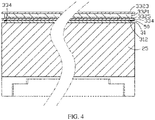
- FIG. 4 is a cross-sectional diagram of a partial structure of the electronic device in a second embodiment of the present disclosure.
- the structure of the second embodiment of the electronic device of the present disclosure is similar to that of the first embodiment, except that: in the second embodiment, two receiving grooves are defined in the surface of the supporting piece 31 facing the protective layer 334 and are adjacent to the left and right sides of the protective layer 334 respectively, and the two elastic adhesives 50 are received and attached to the two receiving grooves 312 respectively, and the surface of each elastic adhesive 50 facing the protective layer 334 exposes out of the surface of the supporting piece 334 facing the protective layer 334, which is convenient for each elastic adhesive 50 to be attached to the protective layer 334.
- Each receiving groove 312 extends along the corresponding outer side of the supporting piece 31, that is, each receiving groove 312 extends along a longitudinal direction of the screen body 332.
- the depth of each receiving groove 312 is slightly smaller than the thickness of the elastic adhesive 50.
- each receiving groove 312 is rectangular, and the cross section of the elastic adhesive 50 is also rectangular.
- the receiving groove 312 can increase the contact area between the elastic adhesive 50 and the supporting piece 334, thereby making the elastic adhesive 50 adhere to the supporting piece 31 and the protective layer 334 more firmly; and the elastic adhesive 50 is partially received in the receiving groove 312 such that the thickness of the flexible display apparatus 30 can be reduced, and the thickness of the electronic device 100 can be thus reduced, which is convenient to carry and use.
- each receiving groove 312 may be triangular, semi-circular, polygonal or irregular
- the cross-section of the elastic adhesive 50 may be triangular, semi-circular, polygonal or irregular
- FIG. 5 is a cross-sectional diagram of a partial structure of the electronic device in a third embodiment of the present disclosure.
- the structure of the third embodiment of the electronic device of the present disclosure is similar to the structure of the first embodiment, except that: in the third embodiment, two receiving grooves 3341 are defined in the surface of the protective layer 334 facing the supporting piece 31 and are adjacent to the left and right sides of the supporting piece 31 respectively.
- the two elastic adhesives 50 are received and attached to the two receiving grooves 3341 respectively.
- One surface of each elastic adhesive 50 facing the supporting piece 31 exposes out of the surface of the protective layer 334 facing the supporting piece 31 so that each elastic adhesive 50 is attached to the supporting piece 31.
- Each receiving groove 3341 extends along the corresponding side of the protective layer 334, that is, the receiving groove 3341 extends along the longitudinal direction of the screen body 332.
- the depth of each receiving groove 3341 is slightly smaller than the thickness of the elastic adhesive 50.
- each receiving groove 3341 is rectangular, and the cross section of the elastic adhesive 50 is also rectangular.
- the receiving groove 3341 can increase the contact area between the elastic adhesive 50 and the protective layer 334, so that the elastic adhesive 50 can be adhered to the protective layer 334 and the supporting piece 31 more firmly; and the elastic adhesive 50 is partially received in the receiving groove 3341 such that the thickness of the flexible display apparatus 30 and the electronic device 100 can be reduced, which is convenient to carry and use.
- each receiving groove 3341 may be triangular, semicircular, polygonal, or irregular
- the cross section of the elastic adhesive 50 may be triangular, semicircular, polygonal, or irregular
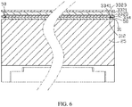
- FIG. 6 is a cross-sectional diagram of a partial structure of the electronic device in a fourth embodiment of the present disclosure.
- the structure of the fourth embodiment of the electronic device of the present disclosure is similar to the structure of the second embodiment, except that: in the fourth embodiment, the protective layer 334 and the supporting piece 31 are defined with corresponding receiving grooves on opposite sides, that is, receiving grooves 3341 are respectively defined in one surface of the protective layer 334 facing the supporting piece 31 adjacent to the left and right sides, and two receiving grooves 312 respectively corresponding to the receiving grooves 3341 are defined in one surface of the supporting piece 31 facing the protective layer 334.
- each elastic adhesive 50 is accommodated and attached to the receiving groove 3341 of the protective layer 334, and another part of the elastic adhesive 50 is accommodated and attached to the receiving groove 312 of the supporting piece 31.
- the elastic adhesive 50 can increase the contact area with the protective layer 334 and the supporting piece 31, so that the elastic adhesive 50 can be adhered to the protective layer 334 and the supporting piece 31 more firmly, and can reduce the thickness of the flexible display apparatus 30. That is, the elastic adhesive 50 does not occupy the thickness of the flexible display apparatus 30.
- FIG. 7 is a schematic diagram of a top view of the electronic device in a fifth embodiment of the present disclosure.
- the structure of the fifth embodiment of the electronic device of the present disclosure is similar to the structure of the first embodiment, except that: in the fifth embodiment, the elastic adhesive 50 which is located at the back surface of the protective layer 334 adjacent to the left and right sides of the supporting piece 31 includes a plurality of elastic adhesive pieces 54, and the elastic adhesive pieces 54 on the same side are distributed along the corresponding side of the supporting piece 31, that is, the elastic adhesive pieces 54 on the same side extend along the longitudinal direction of the screen body 332.
- the plurality of elastic adhesive pieces 54 on the same side are linearly arranged along the side of the supporting piece 31, and adjacent elastic adhesive pieces 54 on the same side are separated from each other by a gap.
- the length of the gap (that is, the distance between adjacent elastic adhesive pieces) is less than the length of each elastic adhesive piece 54.
- the plurality of elastic adhesive pieces 54 on the same side are arranged along the corresponding side of the supporting piece 31.
- the plurality of elastic adhesive pieces 54 in this embodiment can not only make the supporting piece 31 and the protective layer 334 connect firmly, but also save the amount of elastic adhesive 50.
- the elastic adhesive pieces 54 are independent of each other, even if one elastic adhesive piece 54 fails, it will not involve other elastic adhesive pieces 54, so that the overall structure of the electronic device 100 is more stable.
- a plurality of receiving grooves are defined in the surface of the supporting piece 31 facing the protective layer 334 adjacent to the left and right sides of the protective layer 334, and each receiving groove accommodates and attaches one elastic adhesive piece 54.
- a surface of each elastic adhesive piece 54 facing the protective layer 334 exposes out of a surface of the supporting piece 31 facing the protective layer 334, so that each elastic adhesive piece is attached to the protective layer 334.
- a plurality of receiving grooves are respectively defined in the surface of the protective layer 334 facing the supporting piece 31 adjacent to the left and right sides of the supporting piece 31, and each receiving groove accommodates and attaches one elastic adhesive piece 54.
- a surface of each elastic adhesive piece 54 facing the supporting piece 31 exposes out of a surface of the protective layer 334 facing the supporting piece 31, so that each elastic adhesive piece 54 is attached to the supporting piece 31.
- FIG. 8 is a schematic diagram of a top view of the electronic device in a sixth embodiment of the present disclosure.
- the structure of the sixth embodiment of the electronic device of the present disclosure is similar to the structure of the first embodiment, except that: in the sixth embodiment, a plurality of elastic adhesives 50 spaced apart from each other are arranged in the bendable area 3320 between the protective layer 334 and the supporting piece 31.
- Each elastic adhesive 50 is an elastic adhesive strip, and each elastic adhesive strip extends along the side of the supporting piece 31, that is, each elastic adhesive 50 extends along the longitudinal direction of the screen body 332.
- a plurality of the elastic adhesive strips are arranged in array along a width direction of the supporting piece 31, and the plurality of elastic adhesive strips can make the supporting piece 31 and the protective layer 334 connect more firmly, thereby preventing the protective layer 334 from arching in the bendable area 3320.
- FIG. 9 is a schematic diagram of a top view of the electronic device in a seventh embodiment of the present disclosure.
- the structure of the seventh embodiment of the electronic device of the present disclosure is similar to that of the first embodiment, except that: in the seventh embodiment, in addition to the elastic adhesives 50 provided on the left and right sides between the supporting piece 31 and the protective layer 334, the supporting piece 31 and the protective layer 334 are also provided with a plurality of elastic adhesives 50 spaced from each other in the bendable area 3320.
- the plurality of elastic adhesives 50 are distributed along the width direction of the screen body 332.
- Each elastic adhesive 50 includes a plurality of spaced elastic adhesive pieces 54 distributed along the side of the supporting piece 31, that is, the plurality of elastic adhesive pieces 54 are arranged in array along the longitudinal direction of the screen body 332.
- each adhesive piece 54 is rectangular.
- the plurality of elastic adhesive pieces 54 in this embodiment can make the supporting piece 31 and the protective layer 334 connect more firmly, and can save the amount of elastic adhesive 50.
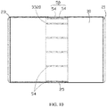
- FIG. 10 is a schematic diagram of a top view of the electronic device in an eighth embodiment of the present disclosure.
- the structure of the eighth embodiment of the electronic device of the present disclosure is similar to the structure of the fifth embodiment, except that: in the eighth embodiment, in addition to the elastic adhesives 50 each composed of a plurality of elastic adhesive pieces 54 are respectively arranged on the left and right sides between the supporting piece 31 and the protective layer 334, a plurality of elastic adhesives 50 spaced apart from each other are also arranged in the bendable area 3320 between the supporting piece 31 and the protective layer 334, and the plurality of the elastic adhesives 50 extend along the length of the screen body 332.
- Each elastic adhesive 50 includes a plurality of spaced elastic adhesive pieces 54 distributed along the side of the supporting piece 31, that is, the plurality of the elastic adhesive pieces 54 are arranged in array along the longitudinal direction of the screen body 332.
- each elastic adhesive piece 54 is rectangular, and the plurality of elastic adhesive pieces 54 can make the supporting piece 31 and the protective layer 334 connect more firmly, and can save the amount of elastic adhesive 50.
- FIG. 11 is a schematic diagram of a top view of an electronic device in a ninth embodiment of the present disclosure.
- the structure of the ninth embodiment of the electronic device of the present disclosure is similar to that of the seventh embodiment, except that: in the ninth embodiment, the plurality of elastic adhesives 50 spaced apart from each other which are located in the bendable area 3320 between the supporting piece 31 and the protective layer 334, each includes a plurality of prismatic elastic adhesive pieces 54 spaced apart from each other.
- the plurality of elastic adhesive pieces 54 can make the supporting piece 31 and the protective layer 334 connect more firmly, and can save the amount of elastic adhesive 50.
- FIG. 12 is a schematic diagram of a top view of the electronic device in a tenth embodiment of the present disclosure.
- the structure of the tenth embodiment of the electronic device of the present disclosure is similar to the structure of the seventh embodiment, except that: in the tenth embodiment, the plurality of elastic adhesives 50 spaced apart from each other which are located in the bendable area 3320 between the supporting piece 31 and the protective layer 334, each includes a plurality of circular elastic adhesive pieces 54 spaced apart from each other.
- the plurality of elastic adhesive pieces 54 can make the supporting piece 31 and the protective layer 334 connect more firmly, and can save the amount of elastic adhesive 50.
- each elastic adhesive piece 54 may also be polygonal, elliptical, or irregular.
- the flexible display screen of the present disclosure may not include or only include any one or more or all of the shading black glue layer, the protective layer and the cover plate.
- X is set to be a sliding direction of the supporting piece 31 relative to the flexible display screen 33
- Y is set to be a thickness direction of the supporting piece 31.
- a manufacturing method for a flexible display apparatus includes the following steps.
- Block S1 a flexible display apparatus 30 including a flexible display screen 33 and a supporting piece 31 is provided, where the flexible display screen 33 includes a bendable area 3320.
- Block S2 an elastic adhesive 50 is arranged between a back surface of the flexible display screen 33 in the bendable area and the supporting piece 31, and the elastic adhesive 50 is located at or near a position between an outer side of the flexible display screen 33 and a corresponding outer side of the supporting piece 31.
- the flexible display screen 33 and the supporting piece 31 are connected through the elastic adhesive 50, and the elastic adhesive 50 seals the gap between the supporting piece 31 and the flexible display screen 33.
- the elastic adhesive 50 is pasted on a front surface of the supporting piece 31 adjacent to the left and right sides, and the back surface of the flexible display screen 33 is stacked on the front surface of the supporting piece 31, so that the elastic adhesive 50 is pasted between the supporting piece 31 and the flexible display screen 33.
- the elastic adhesives 50 on the same side include a plurality of elastic adhesive pieces 54 linearly arranged along the length of the flexible display screen 33.
- the adjacent elastic adhesive pieces 54 are separated from each other by a gap.
- the length of the gap between two adjacent elastic adhesives 54 is less than the length of each elastic adhesive piece 54.
- the front surface of the supporting piece 31 defines receiving grooves 312 adjacent to the left and right sides.
- Two elastic adhesives 50 are respectively received and attached to the corresponding receiving grooves 312.
- Each elastic adhesive 312 exposes out of the front surface of the supporting piece 31 to facilitate each elastic adhesive50 to be pasted on the back surface of the flexible display screen 33.
- a plurality of receiving grooves 3341 are defined in the back surface of the flexible display screen 33 adjacent to the left and right sides.
- the two elastic adhesives 50 are respectively received and attached to the corresponding receiving grooves 3341.
- Each elastic adhesive 50 exposes out of the back surface of the flexible display screen 33 to facilitate the elastic adhesive 50 to be pasted on the front surface of the supporting piece 31.
- the front surface of the supporting piece 31 and the back surface of the flexible display screen 33 are defined with receiving grooves communicated with each other adjacent to the left and right sides, and the elastic adhesives 50 each is accommodated and attached to two communicated receiving grooves.
Landscapes
- Engineering & Computer Science (AREA)
- Theoretical Computer Science (AREA)
- Computer Hardware Design (AREA)
- Physics & Mathematics (AREA)
- General Engineering & Computer Science (AREA)
- General Physics & Mathematics (AREA)
- Human Computer Interaction (AREA)
- Signal Processing (AREA)
- Microelectronics & Electronic Packaging (AREA)
- Devices For Indicating Variable Information By Combining Individual Elements (AREA)
- Mathematical Physics (AREA)
- Liquid Crystal (AREA)
- Laminated Bodies (AREA)
- Electroluminescent Light Sources (AREA)
Abstract
Description
- The present disclosure relates to fields of display devices of electronic devices, and in particular to a flexible display apparatus, an electronic device having the flexible display apparatus, and a manufacturing method for the flexible display apparatus
- With the development of the flexible display screen, the electronic device having a foldable display screen has appeared in the related art. The existing electronic device having the foldable display screen generally realizes a bending of the flexible display screen through a hinge, and realize a support for the flexible display screen through the supporting plate attached to a back surface of the flexible display screen. The supporting plate and the flexible display screen are slidably attached to facilitate bending or flattening of the screen body. However, since the supporting plate and the flexible display screen are in sliding fit, that is, there are slits between the supporting plate and the flexible display screen, so external dust, particles and other debris are easy to enter between the supporting plate and the flexible display screen, which causes the flexible display screen to be worn out, thereby affecting a performance of the display screen.
- The present disclosure provides a flexible display apparatus capable of preventing a back surface of the flexible display screen from being worn out, an electronic device having the flexible display apparatus, and a manufacturing method for the flexible display apparatus.
- A flexible display apparatus described in the present disclosure includes a supporting piece and a flexible display screen arranged on the supporting piece. The flexible display screen includes a bendable area. An elastic adhesive is arranged between a back surface of the flexible display screen in the bendable area and the supporting piece. The elastic adhesive is located at or near a position between an outer side of the flexible display screen and a corresponding outer side of the supporting piece.
- The present disclosure also provides an electronic device, including a housing and a flexible display apparatus. The housing includes a first frame, a second frame, and a hinge connected between the first frame and the second frame. The flexible display apparatus is arranged on the first frame, the second frame and the hinge. The flexible display apparatus includes a supporting piece and a flexible display screen arranged on the supporting piece. The flexible display screen includes a bendable area. An elastic adhesive is arranged between a back surface of the flexible display screen in the bendable area and the supporting piece. The elastic adhesive is located at or near a position between an outer side of the flexible display screen and a corresponding outer side of the supporting piece.
- The present disclosure also provides a manufacturing method for the flexible display apparatus, including following steps.
- A flexible display apparatus including a flexible display screen and a supporting piece is provided, wherein the flexible display screen includes a bendable area.
- An elastic adhesive is arranged between a back surface of the flexible display screen in the bendable area and the supporting piece, and the elastic adhesive is located at or near a position between an outer side of the flexible display screen and a corresponding outer side of the supporting piece. The elastic adhesive connects the flexible display screen and the supporting piece.
- In the present disclosure, an elastic adhesive is arranged between a back surface of the flexible display screen in the bendable area and the supporting piece, and the elastic adhesive is located at or near a position between an outer side of the flexible display screen and a corresponding outer side of the supporting piece. Therefore, the elastic adhesive can prevent dust, particles, or other debris from entering between the supporting plate and the flexible display screen. When the electronic device is bent or flattened through the hinge, it is not easy to cause the back surface of the flexible display screen to be worn out, and the elastic adhesive can prevent the flexible display screen from separating from the supporting piece.
- In order to more clearly describe the technical solutions in the embodiments of the present disclosure, the following will briefly introduce the accompanying drawings needed in the embodiments. Obviously, the accompanying drawings in the following description are only some embodiments of the present disclosure. A person of ordinary skill in the art can obtain other drawings based on these drawings without creative work.
-
FIG. 1 is a schematic diagram of a three-dimensional structure of the electronic device in a first embodiment of the present disclosure. -
FIG. 2 is a schematic diagram of a top view of the electronic device inFIG. 1 . -
FIG. 3 is a schematic diagram of a partial cross-sectional structure along the line III-III inFIG. 1 . -
FIG. 4 is a schematic diagram of a partial cross-sectional structure of an electronic device in a second embodiment of the present disclosure. -
FIG. 5 is a schematic diagram of a partial cross-sectional structure of an electronic device in a third embodiment of the present disclosure. -
FIG. 6 is a schematic diagram of a partial cross-sectional structure of an electronic device in a fourth embodiment of the present disclosure. -
FIG. 7 is a schematic diagram of a top view of the electronic device in a fifth embodiment of the present disclosure. -
FIG. 8 is a schematic diagram of a top view of the electronic device in a sixth embodiment of the present disclosure. -
FIG. 9 is a schematic diagram of a top view of the electronic device in a seventh embodiment of the present disclosure. -
FIG. 10 is a schematic diagram of a top view of the electronic device in an eighth embodiment of the present disclosure. -
FIG. 11 is a schematic diagram of a top view of the electronic device in a ninth embodiment of the present disclosure. -
FIG. 12 is a schematic diagram of a top view of the electronic device in a tenth embodiment of the present disclosure. -
FIG. 13 is a flowchart of a manufacturing method for a flexible display apparatus of an electronic device of the present disclosure. - The technical solutions in the embodiments of the present disclosure will be clearly and completely described below with reference to the accompanying drawings in the embodiments of the present disclosure. Obviously, the described embodiments are only a part of the embodiments of the present disclosure, not all the embodiments. All other embodiments obtained by those of ordinary skill in the art based on the embodiments of the present disclosure without creative work shall fall within the protection scope of the present disclosure.
- In the description of the embodiments of the present disclosure, it should be understood that the orientation or positional relationship indicated by the terms "upper", "lower", "left", "right", etc. is based on an orientation or a positional relationship shown in the drawings, and is only for the convenience of describing the present disclosure and simplifying the description, instead of implying or indicating that the device or element referred to must have a specific orientation, be constructed and operated in a specific orientation, and therefore cannot be understood as a limitation of the present disclosure.
- In the description of the embodiments of the present disclosure, it should be understood that the orientation or positional relationship indicated by the term "thickness" is based on the orientation or the positional relationship shown in the drawings, which is only for the convenience of describing the present disclosure and simplifying the description, and instead of implying or indicating that the device or element referred to must have a specific orientation, be constructed and operated in a specific orientation, so it cannot be understood as a limitation of the present disclosure.
- Referring to
FIGS. 1 to 3 together,FIG. 1 is a schematic diagram of a three-dimensional structure of an electronic device in a first embodiment of the present disclosure;FIG. 2 is a schematic diagram of a top view of the electronic device inFIG. 1 ;FIG. 3 is a schematic diagram of a partial cross-sectional structure along the line III-III inFIG. 1 . Theelectronic device 100 in the first embodiment of the present disclosure includes ahousing 20 and aflexible display apparatus 30 arranged on thehousing 20. Thehousing 20 includes afirst frame 21, asecond frame 23 and ahinge 25 connected between thefirst frame 21 and thesecond frame 23. Theflexible display apparatus 30 is arranged on thefirst frame 21, thesecond frame 23 and thehinge 25. Theflexible display apparatus 30 includes a supportingpiece 31 arranged on thehinge 25 and aflexible display screen 33 arranged on the supportingpiece 31. Theflexible display screen 33 includes ascreen body 332 and aprotective layer 334 fixedly attached to a back surface of thescreen body 332. Thescreen body 332 includes abendable area 3320, anelastic adhesive 50 is arranged between a back surface of theprotective layer 334 in thebendable area 3320 and the supportingpiece 31. Theelastic adhesive 50 is located at or near a position between an outer side of theflexible display screen 33 and a corresponding outer side of the supportingpiece 31. Theelastic adhesive 50 connects the supportingpiece 31 with theprotective layer 334. When theelectronic device 100 is bent or unfolded through thehinge 25, the supportingpiece 31 and theprotective layer 334 of theflexible display screen 33 move relative to each other, and theelastic adhesive 50 is also elastically deformed. The back surface of thescreen body 332 is provided with theprotective layer 334, which can prevent the back surface of theflexible display screen 332 from directly contacting the supportingpiece 31 and being worn; in addition, theelastic adhesive 50 is provided between the supportingpiece 31 and theflexible display screen 33, which can also reduce external dust entering between the supportingpiece 31 and theflexible display screen 33. In this embodiment, the front surface of theflexible display screen 33 refers to a light emitting surface, and the back surface of theflexible display screen 33 refers to a surface facing away from the light emitting surface; the outer side of theflexible display screen 33 and the outer side of the supportingpiece 31 both refer to an outermost edge and an area close to the outermost edge. - In this embodiment, the supporting
piece 31 is a bendable thin steel sheet, and theelastic adhesive 50 is an adhesive strip such as double-sided tape, solid glue, glue, and so on. - In this embodiment, the
electronic device 100 is a mobile phone. It can be understood that, in other embodiments, theelectronic device 100 may be, but is not limited to, a radio phone, a pager, a Web browser, a notebook, a calendar, and/or a PDA of a receiver of a global positioning system (GPS). - The back surface of the
screen body 332 of theelectronic device 100 of the present disclosure is provided with theprotective layer 334, and theelastic adhesive 50 is arranged between the back surface of theprotective layer 334 in thebendable area 3320 and the supportingpiece 31, and theelastic adhesive 50 can seal the gap between the supportingplate 31 and theflexible display screen 332, which can prevent the dust, particles and other debris from entering between the supportingplate 31 and theflexible display screen 332. When theelectronic device 100 is bent or flattened through thehinge 25, it is not easy to cause theflexible display screen 332 to be worn out. In addition, theelastic adhesive 50 can prevent theflexible display screen 33 from separating from the supportingpiece 31 to prevent display failure or damage of theflexible display screen 33. - As shown in
FIG. 3 , theelastic adhesives 50 are arranged on the left and right sides of thebendable area 3320 between theprotective layer 334 and the supportingsheet 31 respectively. The area of theprotective layer 334 corresponding to thebendable area 3320 is slidably stacked on the supportingpiece 31 through theelastic adhesive 50. Theprotective layer 334 can prevent the supportingpiece 31 from wearing the back surface of thescreen body 332. - In this embodiment, a width of the supporting
piece 31 is smaller than a width of theprotective layer 334, that is, the left and right sides of theprotective layer 334 extend out of the left and right sides of the supportingpiece 31, respectively. The left and right sides are the two outer sides of thebendable area 3320 of theelectronic device 100. The left and right sides of the back surface of theprotective layer 334 adjacent to the supportingpiece 31 are respectively provided with theelastic adhesives 50. The twoelastic adhesives 50 are respectively provided on the left and right sides of thebendable area 3320 between the supportingpiece 31 and theprotective layer 334, so as to reduce dust entering between the supportingpiece 31 and theprotective layer 334. - In this embodiment, the
protective layer 334 is a liquid metal sheet, and the liquid metal sheet is fixedly attached to the back surface of thescreen body 332. - In other embodiments, the
protective layer 334 may be a wear-resistant plastic sheet or a wear-resistant rubber sheet fixedly attached to the back surface of thescreen body 332. - The
screen body 332 includes aflexible display plate 3321, acover plate 3323 stacked on a front surface of theflexible display plate 3321, and a shadingblack glue layer 3325 stacked on a back surface of theflexible display plate 3321. Theprotective layer 334 is attached to a surface of the shadingblack glue layer 3325 facing away from theflexible display plate 3321. The width of thecover plate 3323 is greater than the width of theflexible display plate 3321, that is, the left and right sides of thecover plate 3323 extend out of the left and right sides of theflexible display plate 3321, respectively. The width of the shadingblack glue layer 3325 and the width of theflexible display plate 3321 are the same. - In this embodiment, the width of the
screen body 332 is smaller than the width of theprotective layer 334 and shrinks relative to theprotective layer 334, which is beneficial for theprotective layer 334 to better protect thescreen body 332. - In other embodiments, the width of the supporting
piece 31 is the same as the width of theprotective layer 334. - The
elastic adhesive 50 has a long strip shape, and theelastic adhesive 50 extends along the outer side of the supportingpiece 31, that is, theelastic adhesive 50 extends along a longitudinal direction of thescreen body 332. The elastic adhesive 50 seals the gap between the supportingpiece 31 and theprotective layer 334 to prevent dust from entering between the supportingpiece 31 and theprotective layer 334. - The
elastic adhesive 50 is an adhesive strip. When installing theelastic adhesive 50, firstly, one side of the twoelastic adhesives 50 are pasted on the front surface of the supportingpiece 31 adjacent to the left and right sides of the supportingpiece 31 respectively, so that eachelastic adhesive 50 extends along the left and right outer sides of the supportingpiece 31 in thebendable area 3320; then theflexible display screen 33 is stacked on the supportingpiece 31, so that the other side of the twoelastic adhesives 50 are pasted on the back surface of theprotective layer 334, and the twoelastic adhesives 50 are respectively adjacent to the left and right sides of theprotective layer 334. At this time, the twoelastic adhesives 50 are arranged between the supportingpiece 31 and theprotective layer 334, and theelastic adhesive 50 connects the supportingpiece 31 and theflexible display screen 33 to prevent theflexible display screen 33 from separating from the supportingpiece 31. Of course, in other embodiments, the elastic adhesive can also be pasted on the back surface of the protective layer firstly and then pasted on the front surface of the supporting piece to achieve the same effect. - Please referring to
FIG. 4, FIG. 4 is a cross-sectional diagram of a partial structure of the electronic device in a second embodiment of the present disclosure. The structure of the second embodiment of the electronic device of the present disclosure is similar to that of the first embodiment, except that: in the second embodiment, two receiving grooves are defined in the surface of the supportingpiece 31 facing theprotective layer 334 and are adjacent to the left and right sides of theprotective layer 334 respectively, and the twoelastic adhesives 50 are received and attached to the two receivinggrooves 312 respectively, and the surface of eachelastic adhesive 50 facing theprotective layer 334 exposes out of the surface of the supportingpiece 334 facing theprotective layer 334, which is convenient for eachelastic adhesive 50 to be attached to theprotective layer 334. - Each receiving
groove 312 extends along the corresponding outer side of the supportingpiece 31, that is, each receivinggroove 312 extends along a longitudinal direction of thescreen body 332. The depth of each receivinggroove 312 is slightly smaller than the thickness of theelastic adhesive 50. When theelastic adhesive 50 is received and attached to the receivinggroove 312, theelastic adhesive 50 partially exposes out of the surface of the supportingpiece 31 facing theprotective layer 334. - In this embodiment, the cross section of each receiving
groove 312 is rectangular, and the cross section of theelastic adhesive 50 is also rectangular. The receivinggroove 312 can increase the contact area between theelastic adhesive 50 and the supportingpiece 334, thereby making theelastic adhesive 50 adhere to the supportingpiece 31 and theprotective layer 334 more firmly; and theelastic adhesive 50 is partially received in the receivinggroove 312 such that the thickness of theflexible display apparatus 30 can be reduced, and the thickness of theelectronic device 100 can be thus reduced, which is convenient to carry and use. - In other embodiments, the cross-section of each receiving
groove 312 may be triangular, semi-circular, polygonal or irregular, and the cross-section of theelastic adhesive 50 may be triangular, semi-circular, polygonal or irregular. - Please referring to
FIG. 5, FIG. 5 is a cross-sectional diagram of a partial structure of the electronic device in a third embodiment of the present disclosure. The structure of the third embodiment of the electronic device of the present disclosure is similar to the structure of the first embodiment, except that: in the third embodiment, two receivinggrooves 3341 are defined in the surface of theprotective layer 334 facing the supportingpiece 31 and are adjacent to the left and right sides of the supportingpiece 31 respectively. The twoelastic adhesives 50 are received and attached to the two receivinggrooves 3341 respectively. One surface of eachelastic adhesive 50 facing the supportingpiece 31 exposes out of the surface of theprotective layer 334 facing the supportingpiece 31 so that eachelastic adhesive 50 is attached to the supportingpiece 31. - Each receiving
groove 3341 extends along the corresponding side of theprotective layer 334, that is, the receivinggroove 3341 extends along the longitudinal direction of thescreen body 332. The depth of each receivinggroove 3341 is slightly smaller than the thickness of theelastic adhesive 50. When theelastic adhesive 50 is received and attached to the receivinggroove 3341, theelastic adhesive 50 partially exposes out of the surface of theprotective layer 334 facing the supportingpiece 31. - In this embodiment, the cross section of each receiving
groove 3341 is rectangular, and the cross section of theelastic adhesive 50 is also rectangular. The receivinggroove 3341 can increase the contact area between theelastic adhesive 50 and theprotective layer 334, so that theelastic adhesive 50 can be adhered to theprotective layer 334 and the supportingpiece 31 more firmly; and theelastic adhesive 50 is partially received in the receivinggroove 3341 such that the thickness of theflexible display apparatus 30 and theelectronic device 100 can be reduced, which is convenient to carry and use. - In other embodiments, the cross section of each receiving
groove 3341 may be triangular, semicircular, polygonal, or irregular, and the cross section of theelastic adhesive 50 may be triangular, semicircular, polygonal, or irregular. - Please referring to
FIG. 6, FIG. 6 is a cross-sectional diagram of a partial structure of the electronic device in a fourth embodiment of the present disclosure. The structure of the fourth embodiment of the electronic device of the present disclosure is similar to the structure of the second embodiment, except that: in the fourth embodiment, theprotective layer 334 and the supportingpiece 31 are defined with corresponding receiving grooves on opposite sides, that is, receivinggrooves 3341 are respectively defined in one surface of theprotective layer 334 facing the supportingpiece 31 adjacent to the left and right sides, and two receivinggrooves 312 respectively corresponding to the receivinggrooves 3341 are defined in one surface of the supportingpiece 31 facing theprotective layer 334. A part of eachelastic adhesive 50 is accommodated and attached to the receivinggroove 3341 of theprotective layer 334, and another part of theelastic adhesive 50 is accommodated and attached to the receivinggroove 312 of the supportingpiece 31. Theelastic adhesive 50 can increase the contact area with theprotective layer 334 and the supportingpiece 31, so that theelastic adhesive 50 can be adhered to theprotective layer 334 and the supportingpiece 31 more firmly, and can reduce the thickness of theflexible display apparatus 30. That is, theelastic adhesive 50 does not occupy the thickness of theflexible display apparatus 30. - Please referring to
FIG. 7 , which is a schematic diagram of a top view of the electronic device in a fifth embodiment of the present disclosure. The structure of the fifth embodiment of the electronic device of the present disclosure is similar to the structure of the first embodiment, except that: in the fifth embodiment, theelastic adhesive 50 which is located at the back surface of theprotective layer 334 adjacent to the left and right sides of the supportingpiece 31 includes a plurality of elasticadhesive pieces 54, and the elasticadhesive pieces 54 on the same side are distributed along the corresponding side of the supportingpiece 31, that is, the elasticadhesive pieces 54 on the same side extend along the longitudinal direction of thescreen body 332. The plurality of elasticadhesive pieces 54 on the same side are linearly arranged along the side of the supportingpiece 31, and adjacent elasticadhesive pieces 54 on the same side are separated from each other by a gap. The length of the gap (that is, the distance between adjacent elastic adhesive pieces) is less than the length of eachelastic adhesive piece 54. - In this embodiment, the plurality of elastic
adhesive pieces 54 on the same side are arranged along the corresponding side of the supportingpiece 31. The plurality of elasticadhesive pieces 54 in this embodiment can not only make the supportingpiece 31 and theprotective layer 334 connect firmly, but also save the amount ofelastic adhesive 50. In addition, since the elasticadhesive pieces 54 are independent of each other, even if oneelastic adhesive piece 54 fails, it will not involve other elasticadhesive pieces 54, so that the overall structure of theelectronic device 100 is more stable. - In other embodiments, a plurality of receiving grooves are defined in the surface of the supporting
piece 31 facing theprotective layer 334 adjacent to the left and right sides of theprotective layer 334, and each receiving groove accommodates and attaches oneelastic adhesive piece 54. A surface of eachelastic adhesive piece 54 facing theprotective layer 334 exposes out of a surface of the supportingpiece 31 facing theprotective layer 334, so that each elastic adhesive piece is attached to theprotective layer 334. - In other embodiments, a plurality of receiving grooves are respectively defined in the surface of the
protective layer 334 facing the supportingpiece 31 adjacent to the left and right sides of the supportingpiece 31, and each receiving groove accommodates and attaches oneelastic adhesive piece 54. A surface of eachelastic adhesive piece 54 facing the supportingpiece 31 exposes out of a surface of theprotective layer 334 facing the supportingpiece 31, so that eachelastic adhesive piece 54 is attached to the supportingpiece 31. - Please referring to
FIG. 8, FIG. 8 is a schematic diagram of a top view of the electronic device in a sixth embodiment of the present disclosure. The structure of the sixth embodiment of the electronic device of the present disclosure is similar to the structure of the first embodiment, except that: in the sixth embodiment, a plurality ofelastic adhesives 50 spaced apart from each other are arranged in thebendable area 3320 between theprotective layer 334 and the supportingpiece 31. Eachelastic adhesive 50 is an elastic adhesive strip, and each elastic adhesive strip extends along the side of the supportingpiece 31, that is, eachelastic adhesive 50 extends along the longitudinal direction of thescreen body 332. - In this embodiment, a plurality of the elastic adhesive strips are arranged in array along a width direction of the supporting
piece 31, and the plurality of elastic adhesive strips can make the supportingpiece 31 and theprotective layer 334 connect more firmly, thereby preventing theprotective layer 334 from arching in thebendable area 3320. - Please referring to
FIG. 9, FIG. 9 is a schematic diagram of a top view of the electronic device in a seventh embodiment of the present disclosure. The structure of the seventh embodiment of the electronic device of the present disclosure is similar to that of the first embodiment, except that: in the seventh embodiment, in addition to theelastic adhesives 50 provided on the left and right sides between the supportingpiece 31 and theprotective layer 334, the supportingpiece 31 and theprotective layer 334 are also provided with a plurality ofelastic adhesives 50 spaced from each other in thebendable area 3320. The plurality ofelastic adhesives 50 are distributed along the width direction of thescreen body 332. Eachelastic adhesive 50 includes a plurality of spaced elasticadhesive pieces 54 distributed along the side of the supportingpiece 31, that is, the plurality of elasticadhesive pieces 54 are arranged in array along the longitudinal direction of thescreen body 332. - In this embodiment, each
adhesive piece 54 is rectangular. The plurality of elasticadhesive pieces 54 in this embodiment can make the supportingpiece 31 and theprotective layer 334 connect more firmly, and can save the amount ofelastic adhesive 50. As the elasticadhesive pieces 54 are independent of each other, even if oneelastic adhesive piece 54 fails, it will not involve the elasticadhesive pieces 54 in other positions, which makes the overall structure of theelectronic device 100 more stable. - Please referring to
FIG. 10, FIG. 10 is a schematic diagram of a top view of the electronic device in an eighth embodiment of the present disclosure. The structure of the eighth embodiment of the electronic device of the present disclosure is similar to the structure of the fifth embodiment, except that: in the eighth embodiment, in addition to theelastic adhesives 50 each composed of a plurality of elasticadhesive pieces 54 are respectively arranged on the left and right sides between the supportingpiece 31 and theprotective layer 334, a plurality ofelastic adhesives 50 spaced apart from each other are also arranged in thebendable area 3320 between the supportingpiece 31 and theprotective layer 334, and the plurality of theelastic adhesives 50 extend along the length of thescreen body 332. Eachelastic adhesive 50 includes a plurality of spaced elasticadhesive pieces 54 distributed along the side of the supportingpiece 31, that is, the plurality of the elasticadhesive pieces 54 are arranged in array along the longitudinal direction of thescreen body 332. - In this embodiment, each
elastic adhesive piece 54 is rectangular, and the plurality of elasticadhesive pieces 54 can make the supportingpiece 31 and theprotective layer 334 connect more firmly, and can save the amount ofelastic adhesive 50. - Please referring to
FIG. 11, FIG. 11 is a schematic diagram of a top view of an electronic device in a ninth embodiment of the present disclosure. The structure of the ninth embodiment of the electronic device of the present disclosure is similar to that of the seventh embodiment, except that: in the ninth embodiment, the plurality ofelastic adhesives 50 spaced apart from each other which are located in thebendable area 3320 between the supportingpiece 31 and theprotective layer 334, each includes a plurality of prismatic elasticadhesive pieces 54 spaced apart from each other. The plurality of elasticadhesive pieces 54 can make the supportingpiece 31 and theprotective layer 334 connect more firmly, and can save the amount ofelastic adhesive 50. - Please referring to
FIG. 12, FIG. 12 is a schematic diagram of a top view of the electronic device in a tenth embodiment of the present disclosure. The structure of the tenth embodiment of the electronic device of the present disclosure is similar to the structure of the seventh embodiment, except that: in the tenth embodiment, the plurality ofelastic adhesives 50 spaced apart from each other which are located in thebendable area 3320 between the supportingpiece 31 and theprotective layer 334, each includes a plurality of circular elasticadhesive pieces 54 spaced apart from each other. The plurality of elasticadhesive pieces 54 can make the supportingpiece 31 and theprotective layer 334 connect more firmly, and can save the amount ofelastic adhesive 50. - In other embodiments, each
elastic adhesive piece 54 may also be polygonal, elliptical, or irregular. - Understandably, in addition to the screen body, the flexible display screen of the present disclosure may not include or only include any one or more or all of the shading black glue layer, the protective layer and the cover plate.
- The
elastic adhesive 50 of the above embodiments has elasticity, so it can produce tensile deformation when the supportingpiece 31 slides relative to theflexible display screen 33. When the relative position of the supportingpiece 31 and theflexible display screen 33 is restored, theelastic adhesive 50 will automatically shrink and deform to an initial state without being pulled off due to its elasticity. Furthermore, the degree of deformation of theelastic adhesive 50 is proportional to the sliding distance of the supportingpiece 31 relative to theflexible display screen 33, that is, c2=a2+b2, where c is the length of theelastic adhesive 50 after stretching and deformation, and a is the sliding distance of the supportingpiece 31 relative to theflexible display screen 33, b is the distance between the supportingpiece 31 and theflexible display screen 33 in the thickness direction. In other words, the stretching range of theelastic adhesive 50 satisfies
piece 31 relative to theflexible display screen 33, and Y is set to be a thickness direction of the supportingpiece 31. When the supportingpiece 31 slides relative to theflexible display screen 33, theelastic adhesive 50 stretches and deforms in a direction inclined to both X and the thickness direction Y. The stretching direction of theelastic adhesive 50 is inclined to the sliding direction of theflexible display screen 33 relative to the supportingpiece 31. - Referring to
FIG. 13 , a manufacturing method for a flexible display apparatus provided in the present disclosure includes the following steps. - Block S1: a
flexible display apparatus 30 including aflexible display screen 33 and a supportingpiece 31 is provided, where theflexible display screen 33 includes abendable area 3320. - Block S2: an
elastic adhesive 50 is arranged between a back surface of theflexible display screen 33 in the bendable area and the supportingpiece 31, and theelastic adhesive 50 is located at or near a position between an outer side of theflexible display screen 33 and a corresponding outer side of the supportingpiece 31. - The
flexible display screen 33 and the supportingpiece 31 are connected through theelastic adhesive 50, and the elastic adhesive 50 seals the gap between the supportingpiece 31 and theflexible display screen 33. - The
elastic adhesive 50 is pasted on a front surface of the supportingpiece 31 adjacent to the left and right sides, and the back surface of theflexible display screen 33 is stacked on the front surface of the supportingpiece 31, so that theelastic adhesive 50 is pasted between the supportingpiece 31 and theflexible display screen 33. - The
elastic adhesives 50 on the same side include a plurality of elasticadhesive pieces 54 linearly arranged along the length of theflexible display screen 33. The adjacent elasticadhesive pieces 54 are separated from each other by a gap. The length of the gap between two adjacentelastic adhesives 54 is less than the length of eachelastic adhesive piece 54. - The front surface of the supporting
piece 31 defines receivinggrooves 312 adjacent to the left and right sides. Twoelastic adhesives 50 are respectively received and attached to the corresponding receivinggrooves 312. Eachelastic adhesive 312 exposes out of the front surface of the supportingpiece 31 to facilitate each elastic adhesive50 to be pasted on the back surface of theflexible display screen 33. - A plurality of receiving
grooves 3341 are defined in the back surface of theflexible display screen 33 adjacent to the left and right sides. The twoelastic adhesives 50 are respectively received and attached to the corresponding receivinggrooves 3341. Eachelastic adhesive 50 exposes out of the back surface of theflexible display screen 33 to facilitate theelastic adhesive 50 to be pasted on the front surface of the supportingpiece 31. - The front surface of the supporting
piece 31 and the back surface of theflexible display screen 33 are defined with receiving grooves communicated with each other adjacent to the left and right sides, and theelastic adhesives 50 each is accommodated and attached to two communicated receiving grooves. - The above are the preferred embodiments of the present disclosure. It should be pointed out that for those of ordinary skill in the art, without departing from the principle of the present disclosure, several improvements and modifications can be made, and these improvements and modifications are also considered to be the protection scope of the present disclosure.
Claims (25)
- A flexible display apparatus, comprising a supporting piece and a flexible display screen arranged on the supporting piece, wherein the flexible display screen comprises a bendable area, and an elastic adhesive is arranged between a back surface of the flexible display screen in the bendable area and the supporting piece, and the elastic adhesive is located at or near a position between an outer side of the flexible display screen and a corresponding outer side of the supporting piece.
- The flexible display apparatus according to claim 1, wherein the back surface of the flexible display screen is provided with elastic adhesives adjacent to left and right sides of the supporting piece respectively.
- The flexible display apparatus according to claim 1, wherein the back surface of the flexible display screen slides relative to a supporting member when the bendable area is bent.
- The flexible display apparatus according to claim 2, wherein the elastic adhesive has a strip shape, and the elastic adhesive extends along a longitudinal direction of the outer side of the flexible display screen.
- The flexible display apparatus according to claim 2, wherein the elastic adhesives each comprises a plurality of elastic adhesive pieces, and the plurality of elastic adhesive pieces on a same side are distributed along a longitudinal direction of the outer side of the flexible display screen.
- The flexible display apparatus according to claim 5, wherein a gap is formed between two adjacent elastic adhesive pieces on the same side, and a distance between the two adjacent elastic adhesive pieces is smaller than a length of each elastic adhesive piece.
- The flexible display apparatus according to claim 1, wherein the flexible display screen comprises a flexible display plate and a protective layer on a back surface of the flexible display plate, and the protective layer is in sliding contact with the supporting plate.
- The flexible display apparatus according to claim 7, wherein a surface of the supporting piece facing the protective layer defines receiving grooves adjacent to the left and right sides of the protective layer, respectively, and two elastic adhesives are accommodated and attached to corresponding receiving grooves, respectively, and each elastic adhesive partially exposes out of the surface of the supporting piece facing the protective layer to attach to the protective layer.
- The flexible display apparatus according to claim 7, wherein a surface of the protective layer facing the supporting piece defines receiving grooves adjacent to the left and right sides of the supporting piece, respectively, and two elastic adhesives are accommodated and attached to the receiving grooves, respectively, and each elastic adhesive partially exposes out of the surface of the protective layer facing the supporting piece to attach to the supporting piece.
- The flexible display apparatus according to any one of claims 7 to 9, wherein a thickness of the elastic adhesive is greater than a depth of the corresponding receiving groove.
- The flexible display apparatus according to claim 7, wherein a plurality of elastic adhesives spaced apart from each other are arranged in the bendable area between the protective layer and the supporting piece.
- The flexible display apparatus according to claim 11, wherein each elastic adhesive is an elastic adhesive strip, and the elastic adhesive strip extends along a longitudinal direction of the outer side of the flexible display screen.
- The flexible display apparatus according to claim 11, wherein each elastic adhesive comprises a plurality of spaced elastic adhesive pieces, and the plurality of elastic adhesive pieces are distributed along a longitudinal direction of the outer side of the flexible display screen.
- The flexible display apparatus according to claim 7, wherein when the flexible display screen is bent, the supporting piece and the protective layer of the flexible display screen slide relative to each other in the bendable area, and the elastic adhesive produces stretch deformation when the flexible display screen slides relative to the supporting piece.
- The flexible display apparatus according to claim 1, wherein the elastic adhesive has a tensile deformation amplitude that satisfies

- The flexible display apparatus according to claim 7, wherein a stretching direction of the elastic adhesive is inclined to a sliding direction of the protective layer relative to the supporting piece.
- The flexible display apparatus according to claim 7, wherein the protective layer is a liquid metal sheet.
- The flexible display apparatus according to claim 1, wherein the elastic adhesive is a double-sided tape.
- An electronic device comprising a housing, wherein the electronic device further comprises a flexible display apparatus as claimed in any one of claims 1-18, and the housing comprises a first frame, a second frame, and a hinge connected to the first frame and the second frame, the flexible display apparatus is arranged on the first frame, the second frame, and the hinge.
- A manufacturing method for a flexible display apparatus, comprising:providing a flexible display apparatus comprising a flexible display screen and a supporting piece, the flexible display screen comprising a bendable area; andarranging an elastic adhesive between a back surface of the flexible display screen in the bendable area and the supporting piece, and the elastic adhesive being located at or near a position between an outer side of the flexible display screen and a corresponding outer side of the supporting piece.
- The manufacturing method for the flexible display apparatus according to claim 20, wherein the elastic adhesive is pasted on a front surface of the supporting piece adjacent to left and right sides, and the back surface of the flexible display screen is stacked on the front surface of the supporting piece, an elastic adhesive is pasted between the supporting piece and the flexible display screen.
- The manufacturing method for the flexible display apparatus according to claim 21, wherein the elastic adhesives on a same side each comprises a plurality of elastic adhesive pieces linearly arranged along a length of the flexible display screen, and adjacent elastic adhesive are separated from each other by a gap, a length of the gap is less than a length of the elastic adhesive piece.
- The manufacturing method for the flexible display apparatus according to claim 20, wherein a front surface of the supporting piece defines receiving grooves adjacent to left and right sides, and two elastic adhesives are respectively accommodated and attached to the corresponding receiving grooves, each elastic adhesive exposes the front surface of the supporting piece, so that each elastic adhesive can stick to the back surface of the flexible display screen.
- The manufacturing method for the flexible display apparatus according to claim 20, wherein the back surface of the flexible display screen defines receiving grooves adjacent to left and right sides, and two elastic adhesives are respectively accommodated and attached to the corresponding receiving grooves, each elastic adhesive exposes the back surface of the flexible display screen, so that each elastic adhesive can stick to a front surface of the supporting piece.
- The manufacturing method for the flexible display apparatus according to claim 20, wherein a front surface of the supporting piece and the back surface of the flexible display screen are defined receiving grooves interconnected with each other close to the left and right sides, and elastic adhesive is received and attached to one receiving groove.
Applications Claiming Priority (2)
| Application Number | Priority Date | Filing Date | Title |
|---|---|---|---|
| PCT/CN2018/091531 WO2019237340A1 (en) | 2018-06-15 | 2018-06-15 | Flexible screen dust-proof mechanism, electronic device and fabrication method for flexible screen dust-proof mechanism |
| PCT/CN2018/096872 WO2019237455A1 (en) | 2018-06-15 | 2018-07-24 | Flexible display device, electronic device and fabrication method for flexible display device |
Publications (2)
| Publication Number | Publication Date |
|---|---|
| EP3809400A1 true EP3809400A1 (en) | 2021-04-21 |
| EP3809400A4 EP3809400A4 (en) | 2021-08-04 |
Family
ID=65604305
Family Applications (1)
| Application Number | Title | Priority Date | Filing Date |
|---|---|---|---|
| EP18922553.5A Withdrawn EP3809400A4 (en) | 2018-06-15 | 2018-07-24 | FLEXIBLE DISPLAY DEVICE, ELECTRONIC DEVICE, AND MANUFACTURING METHOD FOR A FLEXIBLE DISPLAY DEVICE |
Country Status (4)
| Country | Link |
|---|---|
| US (1) | US11432415B2 (en) |
| EP (1) | EP3809400A4 (en) |
| CN (14) | CN112513961A (en) |
| WO (8) | WO2019237340A1 (en) |
Cited By (2)
| Publication number | Priority date | Publication date | Assignee | Title |
|---|---|---|---|---|
| EP3931664A4 (en) * | 2019-10-22 | 2022-04-20 | Samsung Electronics Co., Ltd. | FOLDABLE ELECTRONIC DEVICE INCLUDING A DISPLAY SCREEN PROTECTIVE STRUCTURE |
| EP4271151A4 (en) * | 2021-05-27 | 2024-07-24 | Samsung Electronics Co., Ltd. | Electronic device comprising waterproof structure |
Families Citing this family (67)
| Publication number | Priority date | Publication date | Assignee | Title |
|---|---|---|---|---|
| CN112513961A (en) * | 2018-06-15 | 2021-03-16 | 深圳市柔宇科技股份有限公司 | Flexible screen dustproof mechanism, electronic device and manufacturing method of flexible screen dustproof mechanism |
| CN111866223B (en) * | 2019-04-25 | 2021-06-01 | Oppo广东移动通信有限公司 | Folding machine shell and electronic device |
| CN111930177B (en) * | 2019-05-13 | 2023-04-04 | 华为技术有限公司 | Foldable electronic equipment |
| PH12023553346A1 (en) | 2019-05-31 | 2024-06-19 | Samsung Electronics Co Ltd | Foldable electronic device including display protection structure |
| WO2020257985A1 (en) * | 2019-06-24 | 2020-12-30 | 深圳市柔宇科技有限公司 | Flexible display device and flexible display module |
| CN110264888B (en) * | 2019-07-02 | 2022-11-04 | 京东方科技集团股份有限公司 | Back film structure, display panel and display device |
| CN110197624B (en) * | 2019-07-09 | 2021-04-09 | 京东方科技集团股份有限公司 | Foldable assembly and foldable display device |
| CN113366927A (en) * | 2019-07-15 | 2021-09-07 | 深圳市柔宇科技股份有限公司 | Folding device and electronic equipment |
| CN112230713A (en) * | 2019-07-15 | 2021-01-15 | 深圳市柔宇科技有限公司 | Folding device and electronic equipment |
| CN111798758B (en) * | 2019-07-16 | 2023-03-31 | 友达光电股份有限公司 | Display device |
| CN113366557A (en) * | 2019-07-17 | 2021-09-07 | 深圳市柔宇科技股份有限公司 | Flexible display device, electronic apparatus, and method of manufacturing flexible display device |
| CN113383379A (en) * | 2019-07-23 | 2021-09-10 | 深圳市柔宇科技股份有限公司 | Electronic equipment and flexible device |
| WO2021012252A1 (en) * | 2019-07-25 | 2021-01-28 | 深圳市柔宇科技有限公司 | Flexible display device and terminal |
| CN110400520B (en) | 2019-07-25 | 2022-02-01 | 京东方科技集团股份有限公司 | Support piece structure, manufacturing method thereof and folding display screen |
| CN110444121B (en) * | 2019-08-22 | 2022-02-08 | 京东方科技集团股份有限公司 | Flexible display module, preparation method thereof and flexible display device |
| CN110728911B (en) * | 2019-10-21 | 2021-09-14 | 云谷(固安)科技有限公司 | Display substrate, display panel and manufacturing method thereof |
| CN112767828A (en) * | 2019-10-21 | 2021-05-07 | 深圳市柔宇科技有限公司 | Bendable device |
| CN112711298A (en) * | 2019-10-25 | 2021-04-27 | 深圳市柔宇科技有限公司 | Flexible device and electronic equipment |
| CN110767095B (en) * | 2019-11-13 | 2022-02-08 | 京东方科技集团股份有限公司 | Flexible display module, preparation method thereof and flexible display device |
| CN110913628B (en) * | 2019-12-06 | 2022-04-15 | Oppo广东移动通信有限公司 | Housing assembly and foldable electronic device |
| CN113037896B (en) * | 2019-12-24 | 2022-06-14 | Oppo广东移动通信有限公司 | Flexible screen components and electronic equipment |
| KR102793995B1 (en) * | 2020-01-13 | 2025-04-14 | 삼성디스플레이 주식회사 | Organic light emitting display device |
| CN212061687U (en) * | 2020-01-20 | 2020-12-01 | 华为技术有限公司 | Electronic device |
| CN111105718B (en) * | 2020-02-20 | 2022-04-19 | 京东方科技集团股份有限公司 | Flexible display module, preparation method thereof and folding display device |
| CN111188972B (en) * | 2020-02-28 | 2022-01-18 | 联想(北京)有限公司 | Screen support and electronic equipment |
| CN111402727B (en) * | 2020-03-12 | 2021-03-23 | 武汉华星光电半导体显示技术有限公司 | Foldable display module |
| CN113409683B (en) * | 2020-03-17 | 2022-12-09 | 上海和辉光电股份有限公司 | Foldable display device |
| CN113628536B (en) * | 2020-05-07 | 2025-11-04 | 北京小米移动软件有限公司 | A foldable screen and electronic device |
| CN111724678A (en) * | 2020-06-08 | 2020-09-29 | 武汉华星光电半导体显示技术有限公司 | Flexible display device and flexible display equipment |
| CN113824819B (en) * | 2020-06-18 | 2022-11-22 | 华为技术有限公司 | Flexible screen assembly and terminal |
| KR20210156893A (en) * | 2020-06-18 | 2021-12-28 | 삼성디스플레이 주식회사 | Display device |
| CN113851041B (en) * | 2020-06-28 | 2023-06-09 | Oppo广东移动通信有限公司 | Display device and bearing device |
| CN111667768B (en) * | 2020-06-30 | 2021-11-16 | 联想(北京)有限公司 | Display device and manufacturing method thereof |
| CN113948000A (en) * | 2020-07-17 | 2022-01-18 | 深圳市柔宇科技股份有限公司 | Folding device and electronic equipment |
| WO2022025671A1 (en) * | 2020-07-29 | 2022-02-03 | 삼성전자 주식회사 | Electronic device including rollable or slidable display |
| CN114067672A (en) * | 2020-07-31 | 2022-02-18 | 深圳市柔宇科技股份有限公司 | Foldable display device and foldable terminal |
| CN112037654B (en) * | 2020-09-08 | 2022-05-31 | 武汉华星光电半导体显示技术有限公司 | Flexible display panel supporting structure and display device |
| CN112071204B (en) * | 2020-09-11 | 2022-10-18 | 维沃移动通信有限公司 | Electronic device |
| CN112037658B (en) * | 2020-09-15 | 2022-07-12 | 武汉华星光电半导体显示技术有限公司 | Flexible display device |
| KR102810222B1 (en) * | 2020-09-28 | 2025-05-20 | 삼성디스플레이 주식회사 | Display device |
| CN112382201A (en) * | 2020-11-17 | 2021-02-19 | 武汉华星光电半导体显示技术有限公司 | Flexible screen folding module and display device |
| CN112930028B (en) * | 2021-01-28 | 2022-11-29 | 优尔爱(常州)医疗科技有限公司 | Flexible electrode with ductility and preparation method |
| CN113098999B (en) * | 2021-03-31 | 2023-05-26 | Oppo广东移动通信有限公司 | Sliding device and electronic equipment |
| CN113066385B (en) * | 2021-04-09 | 2022-09-02 | 昆山国显光电有限公司 | Supporting structure and display device |
| CN113194181B (en) * | 2021-05-08 | 2023-07-25 | 维沃移动通信有限公司 | an electronic device |
| CN113241011B (en) * | 2021-06-02 | 2022-05-31 | 武汉华星光电半导体显示技术有限公司 | Folding display device |
| KR20220165381A (en) * | 2021-06-08 | 2022-12-15 | 엘지디스플레이 주식회사 | Display module and display device including the same |
| CN113380148A (en) * | 2021-06-22 | 2021-09-10 | 京东方科技集团股份有限公司 | Flexible screen module, method for preparing flexible screen module and display device |
| CN113539102B (en) | 2021-07-20 | 2022-09-27 | 武汉华星光电半导体显示技术有限公司 | Supporting component and flexible display module |
| CN113539105B (en) * | 2021-07-23 | 2022-04-26 | 武汉华星光电半导体显示技术有限公司 | Foldable display device |
| CN113938544B (en) * | 2021-09-02 | 2024-11-08 | 深圳市长盈精密技术股份有限公司 | Support assembly and mobile device |
| CN116095204A (en) * | 2021-11-08 | 2023-05-09 | Oppo广东移动通信有限公司 | Electronic equipment, display screen assembly, support piece and preparation method |
| CN113889011B (en) * | 2021-11-09 | 2024-03-22 | 维信诺科技股份有限公司 | Flexible support device and display device |
| CN114034577B (en) * | 2021-11-09 | 2024-05-14 | 合肥维信诺科技有限公司 | Flexible screen bending test fixture and test equipment |
| CN114125101B (en) * | 2021-11-09 | 2024-01-05 | Oppo广东移动通信有限公司 | Electronic equipment |
| CN116266850B (en) * | 2021-12-17 | 2025-11-18 | Oppo广东移动通信有限公司 | Electronic devices and their screen extension mechanisms |
| CN114220352A (en) * | 2021-12-28 | 2022-03-22 | Oppo广东移动通信有限公司 | Electronic device |
| CN114333607B (en) * | 2022-02-25 | 2023-12-12 | 京东方科技集团股份有限公司 | a display device |
| CN115150490B (en) * | 2022-06-22 | 2025-02-07 | Oppo广东移动通信有限公司 | Support sheet and electronic equipment |
| CN117437848A (en) * | 2022-07-13 | 2024-01-23 | 荣耀终端有限公司 | Display device and assembly process of display device |
| CN115348751B (en) * | 2022-07-20 | 2025-02-07 | 深圳市彤兴电子有限公司 | A COF protection device for display screen |
| CN115460311B (en) * | 2022-09-05 | 2025-12-02 | 维沃移动通信有限公司 | Foldable electronic devices |
| CN218670173U (en) * | 2022-09-15 | 2023-03-21 | 荣耀终端有限公司 | Folding mechanism, electronic equipment and dismounting structure |
| CN117156026B (en) * | 2023-01-04 | 2024-10-01 | 荣耀终端有限公司 | Screen assembly structure and assembly method thereof, and electronic device |
| CN115881000B (en) * | 2023-01-31 | 2025-01-28 | 武汉天马微电子有限公司 | A foldable screen |
| CN117133196B (en) * | 2023-08-28 | 2026-02-27 | 京东方科技集团股份有限公司 | A foldable display device and optical adhesive |
| CN118298718B (en) * | 2024-05-10 | 2026-05-12 | 京东方科技集团股份有限公司 | Folding structure and display device |
Family Cites Families (80)
| Publication number | Priority date | Publication date | Assignee | Title |
|---|---|---|---|---|
| JP4045026B2 (en) * | 1997-08-21 | 2008-02-13 | セイコーエプソン株式会社 | Electro-optical device and projection display device including the same |
| JP3473752B2 (en) * | 1999-12-09 | 2003-12-08 | Necアクセステクニカ株式会社 | Dustproof structure in display device and method of assembling dustproof structure |
| JP3984980B2 (en) * | 2004-07-27 | 2007-10-03 | 埼玉日本電気株式会社 | Dust-proof structure of electronic equipment |
| JP4883523B2 (en) * | 2006-03-22 | 2012-02-22 | Nltテクノロジー株式会社 | Liquid crystal display |
| CN201066417Y (en) * | 2007-06-15 | 2008-05-28 | 群康科技(深圳)有限公司 | Touch control LCD device |
| JP2009080164A (en) * | 2007-09-25 | 2009-04-16 | Fujitsu Ltd | Electronic equipment equipped with a liquid crystal display device |
| TWI434249B (en) * | 2010-11-11 | 2014-04-11 | Au Optronics Corp | Display device and method of making the same |
| KR101672345B1 (en) * | 2010-12-08 | 2016-11-04 | 삼성전자주식회사 | Foldable display apparatus |
| TWI457791B (en) * | 2011-05-13 | 2014-10-21 | Wistron Corp | Extended keyboard device |
| KR101876540B1 (en) * | 2011-12-28 | 2018-07-10 | 삼성디스플레이 주식회사 | Flexible display apparatus and the method of manufacturing the same |
| KR20140005404A (en) * | 2012-07-03 | 2014-01-15 | 인텔렉추얼디스커버리 주식회사 | Flexible display device |
| KR102790055B1 (en) * | 2013-07-12 | 2025-04-03 | 가부시키가이샤 한도오따이 에네루기 켄큐쇼 | Light-emitting device |
| KR102076519B1 (en) * | 2013-08-19 | 2020-02-12 | 엘지디스플레이 주식회사 | Flexible display device and manufacturing method thereof |
| KR20150034829A (en) * | 2013-08-30 | 2015-04-06 | 주식회사 엔씰텍 | A supporting substrate using temporary bonding/debonding layer, a method thereof, a method of fabricating a flexible information display device using the same, and a flexible information display device fabriacated by the method |
| US9811120B2 (en) * | 2013-11-28 | 2017-11-07 | Samsung Display Co., Ltd. | Flexible display device |
| KR20160103083A (en) * | 2013-12-24 | 2016-08-31 | 폴리에라 코퍼레이션 | Support structures for an attachable, two-dimensional flexible electronic device |
| CN105336875B (en) * | 2014-07-10 | 2017-10-13 | 上海和辉光电有限公司 | Flexible display device and release method thereof |
| KR102015398B1 (en) * | 2014-07-16 | 2019-08-29 | 엘지디스플레이 주식회사 | Foldable display apparatus |
| KR20210068636A (en) * | 2014-10-28 | 2021-06-09 | 가부시키가이샤 한도오따이 에네루기 켄큐쇼 | Light-emitting device |
| JP6399926B2 (en) * | 2014-12-25 | 2018-10-03 | アルパイン株式会社 | Display device |
| KR20160116122A (en) * | 2015-03-25 | 2016-10-07 | 삼성디스플레이 주식회사 | Display device |
| KR102369943B1 (en) * | 2015-06-25 | 2022-03-03 | 삼성디스플레이 주식회사 | Foldable display |
| CN105185239A (en) * | 2015-08-27 | 2015-12-23 | 京东方科技集团股份有限公司 | Flexible display panel, manufacturing method thereof and flexible display device |
| KR102366516B1 (en) * | 2015-08-31 | 2022-02-22 | 엘지디스플레이 주식회사 | Foldable display apparatus |
| CN106502319B (en) * | 2015-09-08 | 2022-02-22 | Lg电子株式会社 | Mobile terminal and control method thereof |
| CN105044957B (en) * | 2015-09-10 | 2018-11-23 | 京东方科技集团股份有限公司 | A kind of display device |
| US10440840B2 (en) * | 2015-09-24 | 2019-10-08 | Sharp Kabushiki Kaisha | Flexible device |
| US9947882B2 (en) * | 2015-09-25 | 2018-04-17 | Apple Inc. | Electronic devices with robust flexible displays |
| CN105336878A (en) * | 2015-09-29 | 2016-02-17 | 北京维信诺光电技术有限公司 | OLED display device and packaging technology thereof |
| CN105425445B (en) * | 2015-12-17 | 2018-12-28 | 魅族科技(中国)有限公司 | display screen, display screen component and terminal |
| CN105407194A (en) * | 2015-12-29 | 2016-03-16 | 广东欧珀移动通信有限公司 | Mobile terminal with flexible screen |
| CN105513497B (en) * | 2015-12-31 | 2019-11-05 | 京东方科技集团股份有限公司 | A kind of flexible apparatus |
| CN113085302A (en) * | 2016-01-15 | 2021-07-09 | 康宁股份有限公司 | Foldable electronic device assembly and cover element therefor |
| CN105872138B (en) * | 2016-03-29 | 2019-04-26 | 联想(北京)有限公司 | A kind of electronic equipment |
| CN107403873A (en) * | 2016-05-20 | 2017-11-28 | 上海和辉光电有限公司 | A kind of display panel and preparation method thereof, display device |
| CN205809784U (en) * | 2016-06-13 | 2016-12-14 | 厦门光莆显示技术有限公司 | A kind of flat board adhesive frame structure |
| CN205845416U (en) * | 2016-06-18 | 2016-12-28 | 南昌欧菲光科技有限公司 | Display device |
| CN107765907A (en) * | 2016-08-22 | 2018-03-06 | 东莞市健耀烨电子科技有限公司 | A digital device that does not need to distinguish directions |
| KR102697976B1 (en) * | 2016-08-29 | 2024-08-22 | 삼성디스플레이 주식회사 | Rollable display device |
| CN106297568A (en) * | 2016-10-31 | 2017-01-04 | 昆山国显光电有限公司 | Flexible display apparatus |
| CN206112430U (en) * | 2016-11-01 | 2017-04-19 | 京东方科技集团股份有限公司 | Foldable flexible screen's strutting arrangement and display device |
| KR102556395B1 (en) * | 2016-11-03 | 2023-07-17 | 삼성디스플레이 주식회사 | Display device |
| US10465099B1 (en) * | 2016-11-04 | 2019-11-05 | Seagate Technology Llc | Adhesive for processing a microelectronic substrate, and related methods |
| CN108076171B (en) * | 2016-11-17 | 2020-04-03 | 华为技术有限公司 | Folding components and mobile terminals |
| CN108109527B (en) * | 2016-11-24 | 2020-05-19 | 元太科技工业股份有限公司 | Foldable display device and its supporting structure |
| KR101995977B1 (en) * | 2016-11-28 | 2019-07-04 | 삼성디스플레이 주식회사 | Flexible display apparatus |
| CN106782091B (en) * | 2016-12-19 | 2019-06-04 | 上海天马微电子有限公司 | Flexible display panel, manufacturing method thereof, display device and portable terminal |
| CN107995988A (en) * | 2016-12-30 | 2018-05-04 | 深圳市柔宇科技有限公司 | Flexible displays and display devices |
| CN106710452A (en) * | 2017-03-24 | 2017-05-24 | 武汉华星光电技术有限公司 | Flexible display device and bent support |
| CN107026920B (en) * | 2017-04-19 | 2019-05-17 | 维沃移动通信有限公司 | A kind of assembly method of mobile terminal and mobile terminal |
| US20210216103A1 (en) * | 2017-04-20 | 2021-07-15 | Hewlett-Packard Development Company, L.P. | Foldable mechanism for electronic devices |
| CN107102692B (en) * | 2017-04-26 | 2019-08-23 | 京东方科技集团股份有限公司 | folding display device |
| CN106993385B (en) * | 2017-04-28 | 2019-07-23 | 武汉华星光电技术有限公司 | Bendable bottom case and display device |
| CN106910430B (en) * | 2017-05-02 | 2020-04-10 | 京东方科技集团股份有限公司 | Display assembly and mobile device with same |
| CN107193156A (en) * | 2017-05-11 | 2017-09-22 | 青岛海信电器股份有限公司 | A kind of backlight module and its display device |
| WO2018213687A2 (en) * | 2017-05-19 | 2018-11-22 | E Ink Corporation | Foldable electro-optic display including digitization and touch sensing |
| CN107181838B (en) * | 2017-05-26 | 2020-11-10 | 宇龙计算机通信科技(深圳)有限公司 | Flexible display device and mobile terminal with same |
| KR102362080B1 (en) * | 2017-05-31 | 2022-02-10 | 엘지디스플레이 주식회사 | Foldable display device |
| CN107230429B (en) * | 2017-06-08 | 2019-06-25 | 武汉天马微电子有限公司 | Flexible modules and flexible display panels |
| CN107146810A (en) * | 2017-06-19 | 2017-09-08 | 合肥市惠科精密模具有限公司 | A kind of flexible AMOLED display panels |
| US10082838B1 (en) * | 2017-06-21 | 2018-09-25 | Dell Products L.P. | Flexible information handling system display external hinge structure |
| KR101834793B1 (en) * | 2017-07-28 | 2018-03-06 | 엘지디스플레이 주식회사 | Flexible Display and Electronic Device Including the Same |
| CN207268852U (en) * | 2017-08-03 | 2018-04-24 | 深圳市柔宇科技有限公司 | Folding mechanism and terminal |
| CN207115888U (en) * | 2017-08-03 | 2018-03-16 | 深圳市柔宇科技有限公司 | Fold mechanism and terminal |
| CN107564415B (en) * | 2017-08-28 | 2019-06-21 | 上海天马有机发光显示技术有限公司 | Flexible display panel, display device and manufacturing method thereof |
| CN107527556B (en) * | 2017-08-31 | 2020-12-01 | 上海天马微电子有限公司 | Flexible display panel, display device and forming method of flexible display panel |
| CN107437378B (en) * | 2017-09-20 | 2020-09-11 | 上海天马微电子有限公司 | Flexible display module |
| CN107654484A (en) * | 2017-09-26 | 2018-02-02 | 联想(北京)有限公司 | A kind of connection member and flexible display screen, flexible electronic devices |
| KR102398331B1 (en) * | 2017-11-01 | 2022-05-16 | 엘지전자 주식회사 | Flexible display unit and mobile terminal having the same |
| CN107680489A (en) * | 2017-11-07 | 2018-02-09 | 成都爱可信科技有限公司 | A kind of deformable circular display device |
| CN107657895A (en) * | 2017-11-07 | 2018-02-02 | 成都爱可信科技有限公司 | It is a kind of can curved surface deformation display equipment |
| US10777776B2 (en) * | 2017-11-10 | 2020-09-15 | Wuhan China Star Optoelectronics Semiconductor Display Technology Co., Ltd. | Flexible display apparatus and method for fabricating flexible display apparatus |
| KR20170130342A (en) * | 2017-11-21 | 2017-11-28 | 김시환 | A portable display device |
| CN108124028A (en) * | 2017-11-29 | 2018-06-05 | 努比亚技术有限公司 | A kind of folding terminal |
| CN108034373B (en) * | 2017-12-15 | 2020-05-26 | 京东方科技集团股份有限公司 | Frame sealant and preparation method thereof, display panel and preparation method thereof |
| KR102529148B1 (en) * | 2017-12-27 | 2023-05-04 | 엘지디스플레이 주식회사 | Foldable Display Device |
| KR102454623B1 (en) * | 2017-12-29 | 2022-10-13 | 엘지디스플레이 주식회사 | Foldable display device and method of manufacturing the same |
| CN108282560A (en) * | 2018-01-26 | 2018-07-13 | 努比亚技术有限公司 | flexible screen assembly and mobile terminal |
| CN208316809U (en) * | 2018-06-15 | 2019-01-01 | 深圳市柔宇科技有限公司 | Electronic device and its flexible screen dust-proof mechanism |
| CN112513961A (en) * | 2018-06-15 | 2021-03-16 | 深圳市柔宇科技股份有限公司 | Flexible screen dustproof mechanism, electronic device and manufacturing method of flexible screen dustproof mechanism |
-
2018
- 2018-06-15 CN CN201880093868.7A patent/CN112513961A/en active Pending
- 2018-06-15 WO PCT/CN2018/091531 patent/WO2019237340A1/en not_active Ceased
- 2018-07-24 CN CN201821181478.9U patent/CN208737798U/en not_active Expired - Fee Related
- 2018-07-24 WO PCT/CN2018/096872 patent/WO2019237455A1/en not_active Ceased
- 2018-07-24 WO PCT/CN2018/096871 patent/WO2019237454A1/en not_active Ceased
- 2018-07-24 CN CN201821181438.4U patent/CN208737797U/en not_active Expired - Fee Related
- 2018-07-24 CN CN201880093901.6A patent/CN112585664A/en active Pending
- 2018-07-24 EP EP18922553.5A patent/EP3809400A4/en not_active Withdrawn
- 2018-07-24 US US17/252,188 patent/US11432415B2/en active Active
- 2018-07-24 CN CN201880093856.4A patent/CN112639659A/en active Pending
- 2018-08-03 CN CN201821254764.3U patent/CN208596508U/en not_active Expired - Fee Related
- 2018-08-03 CN CN201880093850.7A patent/CN112602138A/en active Pending
- 2018-08-03 WO PCT/CN2018/098644 patent/WO2019237473A1/en not_active Ceased
- 2018-08-09 CN CN201880093853.0A patent/CN112740306A/en active Pending
- 2018-08-09 CN CN201821300584.4U patent/CN208922656U/en not_active Expired - Fee Related
- 2018-08-09 WO PCT/CN2018/099730 patent/WO2019237488A1/en not_active Ceased
- 2018-10-12 CN CN201880093899.2A patent/CN112602308A/en active Pending
- 2018-10-12 CN CN201821661943.9U patent/CN209199496U/en not_active Expired - Fee Related
- 2018-10-12 WO PCT/CN2018/110027 patent/WO2019237598A1/en not_active Ceased
- 2018-10-29 CN CN201880093842.2A patent/CN112602137A/en active Pending
- 2018-10-29 WO PCT/CN2018/112489 patent/WO2019237632A1/en not_active Ceased
- 2018-12-21 CN CN201822181848.5U patent/CN209418053U/en not_active Expired - Fee Related
- 2018-12-21 CN CN201880093851.1A patent/CN112602033A/en active Pending
- 2018-12-21 WO PCT/CN2018/122690 patent/WO2019237706A1/en not_active Ceased
Cited By (7)
| Publication number | Priority date | Publication date | Assignee | Title |
|---|---|---|---|---|
| EP3931664A4 (en) * | 2019-10-22 | 2022-04-20 | Samsung Electronics Co., Ltd. | FOLDABLE ELECTRONIC DEVICE INCLUDING A DISPLAY SCREEN PROTECTIVE STRUCTURE |
| US11592865B2 (en) | 2019-10-22 | 2023-02-28 | Samsung Electronics Co., Ltd. | Foldable electronic device including display protection structure |
| EP4220347A1 (en) * | 2019-10-22 | 2023-08-02 | Samsung Electronics Co., Ltd. | Foldable electronic device including display protection structure |
| US12045089B2 (en) | 2019-10-22 | 2024-07-23 | Samsung Electronics Co., Ltd. | Foldable electronic device including display protection structure |
| EP4271151A4 (en) * | 2021-05-27 | 2024-07-24 | Samsung Electronics Co., Ltd. | Electronic device comprising waterproof structure |
| US12133348B2 (en) | 2021-05-27 | 2024-10-29 | Samsung Electronics Co., Ltd. | Electronic device including waterproof structure |
| EP4597999A3 (en) * | 2021-05-27 | 2025-09-17 | Samsung Electronics Co., Ltd. | Electronic device comprising waterproof structure |
Also Published As
| Publication number | Publication date |
|---|---|
| WO2019237340A1 (en) | 2019-12-19 |
| WO2019237598A1 (en) | 2019-12-19 |
| CN208737798U (en) | 2019-04-12 |
| CN112602137A (en) | 2021-04-02 |
| CN112513961A (en) | 2021-03-16 |
| WO2019237632A1 (en) | 2019-12-19 |
| CN112740306A (en) | 2021-04-30 |
| WO2019237488A1 (en) | 2019-12-19 |
| CN208737797U (en) | 2019-04-12 |
| CN208596508U (en) | 2019-03-12 |
| WO2019237455A1 (en) | 2019-12-19 |
| CN112602138A (en) | 2021-04-02 |
| CN112602308A (en) | 2021-04-02 |
| EP3809400A4 (en) | 2021-08-04 |
| CN112602033A (en) | 2021-04-02 |
| CN209418053U (en) | 2019-09-20 |
| WO2019237706A1 (en) | 2019-12-19 |
| CN112639659A (en) | 2021-04-09 |
| US20210267073A1 (en) | 2021-08-26 |
| WO2019237473A1 (en) | 2019-12-19 |
| CN112585664A (en) | 2021-03-30 |
| CN209199496U (en) | 2019-08-02 |
| US11432415B2 (en) | 2022-08-30 |
| WO2019237454A1 (en) | 2019-12-19 |
| CN208922656U (en) | 2019-05-31 |
Similar Documents
| Publication | Publication Date | Title |
|---|---|---|
| US11432415B2 (en) | Flexible display apparatus, electronic device and manufacturing method for flexible display apparatus | |
| KR101908878B1 (en) | Electronic device having flexible screen | |
| CN112470096A (en) | Flexible display screen supporting mechanism and flexible display device | |
| JP6391248B2 (en) | Flexible portable terminal device | |
| US20240157669A1 (en) | Display module and display apparatus | |
| CN208316809U (en) | Electronic device and its flexible screen dust-proof mechanism | |
| WO2019237337A1 (en) | Electronic apparatus and flexible screen supporting mechanism thereof | |
| US8316591B2 (en) | Solar cell module device | |
| KR20140101295A (en) | Flexible terminal device | |
| KR20180052291A (en) | Electronic device with side speaker hole | |
| CN106843388B (en) | Display panel assembly and its assembly method and electronic device | |
| US10444795B2 (en) | Glass cover plate for a display assembly, display assembly, and terminal | |
| CN111131570A (en) | Display module for folding screen and electronic equipment thereof | |
| CN114038324A (en) | Supporting assembly and flexible display device | |
| CN220189162U (en) | Display components and electronic devices | |
| CN110167304A (en) | Electronic device | |
| CN106790823A (en) | Display component, assembly method thereof, and electronic device | |
| CN209420084U (en) | Electronic equipment and its 3D cover assembly, 3D cover | |
| US8541697B2 (en) | Dustproof structure and electronic device employing the same | |
| CN112711298A (en) | Flexible device and electronic equipment | |
| CN209980123U (en) | Electronic device and flexible screen folding device thereof | |
| CN209859506U (en) | Flexible display device | |
| CN114373795A (en) | Back film, display module and display device | |
| US20160337488A1 (en) | Electronic device | |
| US20220140278A1 (en) | Flexible display device |
Legal Events
| Date | Code | Title | Description |
|---|---|---|---|
| STAA | Information on the status of an ep patent application or granted ep patent |
Free format text: STATUS: THE INTERNATIONAL PUBLICATION HAS BEEN MADE |
|
| PUAI | Public reference made under article 153(3) epc to a published international application that has entered the european phase |
Free format text: ORIGINAL CODE: 0009012 |
|
| STAA | Information on the status of an ep patent application or granted ep patent |
Free format text: STATUS: REQUEST FOR EXAMINATION WAS MADE |
|
| 17P | Request for examination filed |
Effective date: 20210108 |
|
| AK | Designated contracting states |
Kind code of ref document: A1 Designated state(s): AL AT BE BG CH CY CZ DE DK EE ES FI FR GB GR HR HU IE IS IT LI LT LU LV MC MK MT NL NO PL PT RO RS SE SI SK SM TR |
|
| AX | Request for extension of the european patent |
Extension state: BA ME |
|
| A4 | Supplementary search report drawn up and despatched |
Effective date: 20210706 |
|
| RIC1 | Information provided on ipc code assigned before grant |
Ipc: G06F 1/16 20060101AFI20210630BHEP Ipc: H04M 1/02 20060101ALI20210630BHEP Ipc: H04M 1/18 20060101ALI20210630BHEP |
|
| STAA | Information on the status of an ep patent application or granted ep patent |
Free format text: STATUS: THE APPLICATION HAS BEEN WITHDRAWN |
|
| 18W | Application withdrawn |
Effective date: 20210809 |