EP3808217A1 - Vorrichtung zum verbinden eines frontbauteils eines bewegbaren möbelteils mit einem seitenbauteil des bewegbaren möbelteils - Google Patents
Vorrichtung zum verbinden eines frontbauteils eines bewegbaren möbelteils mit einem seitenbauteil des bewegbaren möbelteils Download PDFInfo
- Publication number
- EP3808217A1 EP3808217A1 EP20199655.0A EP20199655A EP3808217A1 EP 3808217 A1 EP3808217 A1 EP 3808217A1 EP 20199655 A EP20199655 A EP 20199655A EP 3808217 A1 EP3808217 A1 EP 3808217A1
- Authority
- EP
- European Patent Office
- Prior art keywords
- locking
- locking element
- front component
- bearing
- movable furniture
- Prior art date
- Legal status (The legal status is an assumption and is not a legal conclusion. Google has not performed a legal analysis and makes no representation as to the accuracy of the status listed.)
- Granted
Links
Images
Classifications
-
- A—HUMAN NECESSITIES
- A47—FURNITURE; DOMESTIC ARTICLES OR APPLIANCES; COFFEE MILLS; SPICE MILLS; SUCTION CLEANERS IN GENERAL
- A47B—TABLES; DESKS; OFFICE FURNITURE; CABINETS; DRAWERS; GENERAL DETAILS OF FURNITURE
- A47B88/00—Drawers for tables, cabinets or like furniture; Guides for drawers
- A47B88/90—Constructional details of drawers
- A47B88/944—Drawers characterised by the front panel
- A47B88/95—Drawers characterised by the front panel characterised by connection means for the front panel
-
- A—HUMAN NECESSITIES
- A47—FURNITURE; DOMESTIC ARTICLES OR APPLIANCES; COFFEE MILLS; SPICE MILLS; SUCTION CLEANERS IN GENERAL
- A47B—TABLES; DESKS; OFFICE FURNITURE; CABINETS; DRAWERS; GENERAL DETAILS OF FURNITURE
- A47B88/00—Drawers for tables, cabinets or like furniture; Guides for drawers
- A47B88/90—Constructional details of drawers
- A47B88/944—Drawers characterised by the front panel
- A47B88/95—Drawers characterised by the front panel characterised by connection means for the front panel
- A47B2088/954—Drawers characterised by the front panel characterised by connection means for the front panel fastening the front panel by a sprung bolt, latch or lock-bolt
Definitions
- the invention relates to a device for connecting a front component of a movable furniture part to a side component of the movable furniture part.
- Two-part connecting means are often used to connect a front component and a side component of a movable furniture part, in particular a drawer.
- a part of the connecting means is attached to each component of the movable furniture part.
- the two components, the front component and the side component can then be connected to one another via the connecting means.
- the object of the invention is to provide an improved device for connecting a front component of a movable furniture part to a side component of the movable furniture part.
- the invention is based on a device for connecting a front component of a movable furniture part to a side component of the movable furniture part, the device being designed to be attached to the side component of the movable furniture part.
- the device is preferably a furniture connection device.
- the movable furniture part is designed as a drawer or as a drawer.
- the movable furniture part comprises a front component, in particular a drawer front and a side component, in particular a frame or a drawer side wall and / or a drawer frame.
- the front component can be produced from wood and / or metal and / or plastic and / or a composite material.
- the side component of the movable furniture part can be produced from wood and / or metal and / or plastic and / or a composite material.
- the side component preferably has a length.
- the side component also has a height, for example.
- a plane is spanned by the length and the height, which, for example, forms a main plane of the side component.
- the device has a locking unit, a fastening element, a spring element and a locking member, the locking unit comprising a locking element, the fastening element being designed to be arranged in a fixed position on the side component, the locking unit is mounted on the fastening element so as to be pivotable about a pivot axis, the locking element being designed to be arranged on the front component, the locking element being lockable with the locking element in the arranged state on the movable furniture part, the locking element being provided with force by the spring element, so that the locking element during a locking process with the locking member can be pivoted against a force of the spring element about the pivot axis, the locking unit having a bearing element and a restoring device, whereby i the locking element is mounted on the bearing element so as to be linearly displaceable, the locking element being movable relative to the bearing element by means of the restoring device.
- the locking unit is movably present along a plane of the side component.
- the locking unit can preferably be moved along the main plane of the side component, or in a plane that is parallel to the main plane.
- the locking unit is, for example, pivotable relative to the fastening element.
- the locking unit is advantageously pivotably mounted on the fastening element via a pivot mount.
- the locking unit is preferably attached at a distance from the fastening element.
- the swivel mount is formed between the locking unit and the fastening element.
- the swivel mount can be arranged between the bearing element and the fastening element.
- the bearing element is pivotable, in particular rotatable, about the pivot axis relative to the fastening element.
- the spring element can be arranged between the locking unit and the fastening element, in particular between the bearing element and the fastening element.
- the spring element is preferably connected with a first end, in particular directly with the bearing element, and with a second end, in particular directly with the fastening element.
- the first and the second end of the spring element are advantageously present opposite one another and spaced apart from one another.
- the locking unit advantageously comprises the swivel mount.
- the swivel mount preferably has the swivel axis about which the swivel mount is pivotably mounted.
- the pivot axis is angled at a connection point between the pivot mount and the fastening element, in particular perpendicular to the main plane of the side component.
- the fastening element is preferably firmly, in particular non-detachably, connectable to the side component.
- that is Fastening element can be welded or riveted to the side component.
- the fastening element is present, for example, in one piece on the side component.
- the fastening element is elongated.
- the fastening element has two ends which are spaced apart from one another, a first end preferably being oriented closer to the front component than a second end.
- the fastening element can be aligned approximately parallel to an edge of the side component, in particular to the edge in the longitudinal extension of the movable furniture part.
- the spring element is designed as a compression spring or as a tension spring.
- the spring element can be positioned at the end of the fastening element that faces the front component.
- the spring element is designed, for example, as a helical spring.
- the spring element can be positioned on the fastening element in such a way that the spring element is further away from the front component than the swivel mount.
- the tension spring is designed as a helical spring.
- a spring force of the spring element preferably presses or pulls the locking unit into a rest position.
- the spring element preferably engages, in particular directly on the bearing element and / or in particular directly on the fastening element.
- the locking element and the restoring device are arranged on the bearing element.
- the bearing element is preferably attached to the fastening element via the swivel mount.
- the components of the locking unit, bearing element and / or locking element and / or Resetting device made of metal.
- the bearing element and / or the locking element and / or the resetting device consist of a plastic and / or a composite material.
- the bearing element is preferably formed from a sheet metal material.
- the bearing element is bent into a shape.
- the bearing element has a flat side with a length and a height.
- a further side is advantageously angled, in particular perpendicular to the flat side of the bearing element.
- the other side of the bearing element extends, for example, in one width.
- the bearing element is preferably attached to the fastening element via the swivel mount.
- the locking element advantageously comprises a stop member, by means of which an in particular linear movement of the locking element relative to the bearing element is limited.
- the bearing element comprises a stop element on which the stop element rests in a stop position and thereby limits the movement of the locking element relative to the bearing element.
- the stop member is present, for example, as a bent tab on the locking element.
- the stop element is present, for example, as a recess on the bearing element.
- the tab of the locking element is movably arranged in the recess of the bearing element.
- the bearing element includes the swivel mount.
- the bearing element and the fastening element are connected to one another via the pivot mount.
- the bearing element is pivotably arranged on the fastening element by means of the pivot mount.
- the swivel mount is arranged at the second end of the fastening element, which is at a greater distance from the front component, in particular than the spring element.
- the swivel mount is formed in one piece on the bearing element. It is also possible to connect the swivel mount to the bearing element, for example by welding, soldering, gluing, riveting or the like.
- the locking element is slidably and / or pivotably mounted on the bearing element, in particular in a guided manner.
- the bearing element has one or more passages, in particular two passages, for the locking element.
- the implementation is, for example, a recess in the material from which the bearing element is made.
- the bushing is preferably bent out of the bearing element and protrudes at an angle, in particular perpendicularly, from the flat side of the bearing element.
- the leadthrough also has a slot, for example.
- the implementation is designed as a slot or as a tab.
- the locking element can be positioned in the slot, for example.
- the relative alignment of the bearing element and the locking element results from the recesses and / or from the resetting device.
- the locking element is preferably moved relative to the bearing element. In particular, the locking element can be moved via the reset device.
- the bearing element comprises an operating option, for example an operating structure.
- the operating option is designed as a serrated or serrated structure.
- the operating option is preferably arranged at the second end of the bearing element.
- the dimension of the operating option is advantageously based on the dimension of a screwdriver, for example Phillips screwdriver or Pozi screwdriver, matched.
- the bearing element comprises a holding surface.
- the bearing element preferably has four holding surfaces.
- the holding surfaces are preferably arranged in pairs.
- the holding surfaces are attached to the upper end of the bearing element.
- a holding surface is advantageously a region of the bearing element which is arranged at an angle, in particular perpendicular to a side surface of the bearing element, in particular is bent.
- the locking element is advantageously designed as a lever.
- the resetting device advantageously comprises an actuating element.
- the adjusting element of the restoring device is rotatably received in the bearing element and the adjusting element interacts with an engagement structure, in particular with cams, on the locking element.
- the locking element has a hook element at one end.
- the hook element is preferably attached to the locking element in a non-detachable manner.
- the hook element is formed in one piece on the locking element.
- elevations for example cams
- the elevations preferably form an engagement structure on the locking element.
- the engagement structure is made from the material of the locking element, in particular bent out. An additional application of material to the locking element for producing the elevations is also conceivable.
- the engagement structure of the locking element is matched to a guide contour of the reset device.
- the reset device is designed as a worm drive.
- the reset device is designed as an eccentric drive.
- the adjusting element is rotatably mounted on the bearing element.
- the adjusting element is rotatably received in a recess on the bearing element.
- the adjusting element of the resetting device is preferably a circular disk with a circumference.
- the disk of the adjusting element has a flattening, for example a straight section, along one circumference.
- the disk advantageously has two sides which are arranged opposite one another and at a distance from one another.
- a guide contour e.g. in the form of an elevation, is preferably provided on both sides of the disk of the adjusting element.
- the guide contour is designed as a, for example, spiral-shaped elevation on one side of the actuating element.
- the guide contour is designed as a contour raised from the surface of the pane, in particular as a web-shaped protruding guide contour.
- a tool for example a screwdriver
- the possibility of engagement is arranged on one side of the disk of the actuating element, in particular opposite the guide structure.
- the possibility of engagement is advantageously matched to the screwdriver, in particular as a slot-shaped and / or cross-slot-shaped engagement option.
- the worm drive by turning the screwdriver.
- the worm drive preferably produces a linear one Movement of the locking element relative to the bearing element.
- the guide contour of the resetting device engages in the engagement structure on the locking element.
- the locking element can be moved linearly to the bearing element.
- the device is designed in such a way that a superimposed movement takes place by means of the actuating element. It is also conceivable that the device is present in such a way that first a linear movement and then a pivoting movement of the actuating element relative to the bearing element takes place due to a rotation of the actuating element, or vice versa.
- the linear movement is advantageously oriented transversely, in particular perpendicular to the pivot axis of the pivot mount.
- a swivel axis is advantageously provided in the direction of or parallel to the swivel axis of the swivel mount.
- the locking member is preferably designed essentially in the shape of a pin, in particular in the shape of a cylinder.
- the locking member can preferably be configured to protrude from the front component, in particular perpendicular to the surface of the front component.
- the locking member has a head section and an adjoining pin section that is reduced in diameter to the head section.
- the pin section can be attached to the front component and is then protruding therefrom.
- the head section is preferably the region of the locking member which is most distant from the front component.
- connection between the front component and the side component can take place in two stages, with the locking element and the
- the locking member is connected to the locking member by snapping or reaching behind the locking member and in a second stage the locking member is movable relative to the bearing element via the restoring device, so that the distance between the front component and the side component can be reduced.
- the device preferably enables a simple assembly of the front component of the movable furniture part with the side component of the movable furniture part. This is given, for example, by the two-stage process.
- the front component is preferably attached to the side component by the device, so that it can no longer fall down, for example.
- the front component can be drawn closer to the side component if necessary.
- the device is designed to produce a non-positive connection between the front component and the side component.
- the front component can be pulled towards the side component in a clamping movement.
- the clamping movement is particularly important for tall front components.
- the hook element when the front component is pushed on, the hook element is pushed away over an inclined edge.
- the pivoting away of the hook element on the locking element takes place preferably against the force of the spring element.
- the head section of the locking member preferably slides over the inclined edge of the hook element.
- a slope in particular a run-on slope, is preferably also formed on the head section of the locking member.
- the bevel on the hook element and the bevel on the head section are matched to one another, so that the locking member can slide over the hook element.
- the head section of the locking member is advantageously held behind the hook element. If, for example, the head section of the locking element is behind the hook element, the pin section of the locking element lies between the two side surfaces of the U, which, for example, forms the hook element.
- the locking unit engages, in particular the locking element engages behind the locking member.
- a transmission of force from the locking element to the locking member is possible; in particular, the front component can be pulled against the side component.
- the preferred configuration of the two parts of the device creates a detachable connection.
- An unlocking mechanism is advantageously provided with which the locking element can be pivoted away from the locking element, in particular against the spring force of the spring element, so that the locking element is released.
- the hook element is first released from the head section of the locking member via the restoring device, in particular moved away linearly.
- the locking element is pivoted away from the locking element, in particular against the spring force of the spring element, and the locking element is thus released.
- a linear movement of the locking element relative to the bearing element and led to the locking member is advantageously, a connection, in particular a force-fit connection, between the locking element and the hook element and thus in particular between the front component and the side component to be released.
- the locking element is advantageously pivoted away by the unlocking mechanism against the spring force of the spring element.
- the locking element is preferably pivoted away by the unlocking mechanism via the worm drive.
- the actuating element can be moved by engaging the engagement facility, for example by means of a screwdriver.
- a movement of the unlocking mechanism can thereby be carried out.
- the unlocking mechanism includes the worm drive.
- the device is advantageously designed in such a way that, when unlocking by means of a worm drive, there is first a linear movement of the locking element relative to the bearing element. For example, the hook element of the locking element is released from the locking member. As a result of the selected configuration of the device, a further movement can then take place, for example, in particular in a further direction in the same plane. For example, this further movement of the locking element enables the device to pivot the hook element away from the head section of the locking member. This movement is guided, for example, by the engagement structure of the adjusting element and the guide contour on the locking element.
- the engagement structure is advantageously designed in such a way that a linear movement and / or a pivoting movement offset thereto is possible by means of a rotary movement of the actuating element.
- the movements when unlocking and the movement when locking the device are preferably carried out in the same way Level.
- the locking member can be released by the unlocking mechanism.
- an operating option for engaging a tool is attached to the end of the locking unit, in particular on the bearing element.
- the locking element is pivoted away.
- the locking element can preferably be moved downward so far that the locking member is released.
- An advantageous variant of the invention is a side component, in particular a drawer side wall, with a device as described above.
- Another advantageous embodiment of the invention is a piece of furniture with a side component and a device as described above.
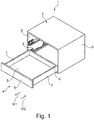
- FIG Figure 1 A piece of furniture 1 according to the invention with a box-shaped furniture body 2 and a drawer 4 guided movably via guide means 3 is shown in FIG Figure 1 shown.
- the drawer 4 is shown in an open position relative to the furniture body 2.
- the drawer 4 comprises, for example, a drawer bottom 5, a front component 6, two opposite side components 7 and a drawer rear wall 8.
- two guide means 3 with the same effect are provided between each side component 7 of the drawer 4 and an associated body side wall 9.
- the drawer 4 is mounted displaceably in an opening direction M1 and in a closing direction M2 via the guide means 3 on the furniture body 2.
- the guide means 3 comprise, for example, two similar partial or full extensions.
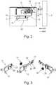
- FIG. 2 shows a device 10 according to the invention.
- the device 10 is shown in the installed state on the side component 7.
- the device 10 comprises a locking unit 11, a fastening element 12, a spring element 13 and a locking member 14.
- the locking unit 11 is preferably attached to the fastening element 12, in particular movably, via the spring element 13 and a swivel mount 19.
- the spring element 13 has a spring force, for example.
- the swivel mount 19 preferably has a swivel axis S. In particular, the pivot axis S is oriented perpendicular to the plane of movement of the pivot mount 19.
- the locking unit 11 comprises a bearing element 15, a locking element 16 and an actuating element 17.
- the locking member 14 can preferably be arranged in a protruding manner on the front component 6.
- the locking element 14 comprises a head section 23 and a pin section 24.
- the dimensions of the locking element 14 are preferably selected so that it can interact with a hook element 21 on the locking element 16.
- the hook element 21 is curved, for example U-shaped.
- the hook element 21 comprises, in particular in the U-shape, a plurality of spaced apart, for example exactly two, opposite surfaces 27. In a preferred variant, these surfaces 27 form the two sides of the U-shape.
- the surfaces 27 together with a connecting web 28 form the hook element 21.
- the connecting web 28 of the hook element 21 has a length, for example. The length of the connecting web preferably corresponds to the distance between the two surfaces 27 of the hook element 21. For example, the distance between the surfaces 27 of the hook element 21 is matched to the dimensions of the locking member 14.
- the surfaces 27 of the hook element 21 are preferably approximately rectangular. In one embodiment, the surfaces 27 have a beveled side in the form of, for example, a bevel. The surfaces 27 of the hook element 21 have, for example, the shape of an irregular pentagon.
- the surfaces 27 are preferably designed to be the same.
- the surfaces 27 are advantageously congruent in a side view in the direction of the pivot axis S through the pivot mount 19.
- the bevels are preferably located on the side of the hook element 21 which, in the assembled state, faces the locking member 14 and the front component 6.
- the head section 23 and the pin section 24 of the locking member are advantageously designed to be approximately cylindrical.
- the pin section 24 protrudes from the front component 6.
- the pin section 24 protrudes perpendicularly from the front component 6.
- the head section 23 adjoins the pin section 24.
- the head section 23 is spaced apart from the front component 6 via the pin section 24.
- the head section 23 and the pin section 24 preferably each have one Diameter on.
- the diameter of the head section 23 is preferably greater than the diameter of the pin section 24 of the locking member 14.
- the locking unit 11 is brought into a rest position by the spring element 13, as in FIG Figure 2 shown, brought.
- one end of the spring element 13 is attached directly to the fastening element 12. More preferably, the spring element 13 is attached directly to the bearing element 15 with a further end.
- the spring element 13 is advantageously designed as a compression spring, for example a helical spring.
- the spring element 13 has a height H. In particular, the height H is the length of the spring element 13 in the rest state.
- the spring element 13 is not acted upon by a force in the rest state, in particular not compressed or stretched.
- the height H of the helical spring of the spring element 13 is preferably adapted to a height H ′ of the swivel mount 19.
- the height H of the spring element 13 and the height H 'of the swivel mount 19 are advantageously selected such that the locking unit 11 is arranged, for example, approximately parallel, in particular parallel to the fastening element 12.
- the front component 6 is mounted on the side component 7 in a direction M3.
- the front component 6 is preferably moved towards the side component 7 during assembly.
- the locking member 14 is pushed onto the locking element 16 in the direction M3.
- the side component 7 and the front component 6 are dismantled in a direction M4.
- the direction M4 is opposite to the direction M3.
- the locking member 14 is moved away from the locking element 16 in the direction M4.
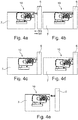
- FIG. 3 a) to 3 c) the locking unit 11 is shown.
- the locking unit 11 is shown in the assembled state.
- the other two representations Figure 3 b) and Figure 3 c) each show an exploded view of the locking unit 11 in different views.
- the components of the locking unit 11 are shown in a view that is a plan view from FIG Figure 2 corresponds to.
- Figure 3 c) the sides opposite to view 3 b) are visible.
- the locking unit 11 in the embodiment according to FIG Figure 3 a bearing element 15, a locking element 16 and an adjusting element 17.
- the adjusting element 17 is advantageously designed as a disk, in particular a circular disk.
- the adjusting element 17 as a disk comprises, for example, two sides, in particular two opposite sides of the disk.
- the adjusting element 17 is movably, in particular rotatably, received on the bearing element 15.
- the actuating element 17 shown has a guide contour 18.
- the guide contour 18 is designed as a web-shaped contour raised from the surface.
- a means of engagement 22 for a screwdriver is also arranged on the adjusting element 17.
- the guide contour 18 is preferably arranged on one side of the adjusting element 17 and the possibility of engagement 22 on an opposite side.
- the locking element 16 is guided via one or more passages 25 of the bearing element 15 on the bearing element 15.
- the locking element 16 further comprises, for example, an engagement structure 20 and the hook element 21.
- the dimensions of the guide contour 18 of the actuating element 17 are preferably matched to the engagement structure 20 of the locking element 16.
- the guide contour 18 is a spiral contour educated.
- a worm drive advantageously results together with the engagement structure 20, for example designed as a cam.
- the adjusting element 17 with the guide contour 18 and the engagement structure 20 of the locking element 16 form a restoring device.
- the pivot mount 19 is preferably formed in one piece on the bearing element 15.
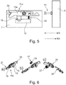
- FIGS 4 a) to c) show an exemplary sequence during assembly (direction M3) of the front component 6 on the side component 7. Further is in FIG Figures 4 d) and e) the dismantling (direction M4) of the front component 6 and the side component 7 is shown.
- the hook element 21 of the locking element 16 is advantageously moved by the locking element 14, in particular pressed downwards (see FIG Figure 4 a) ), in a direction towards the fastening element 12. For example, this takes place against the spring force of the spring element 13 and about the pivot axis S of the pivot mount 19. If the front component 6 is advantageously pushed on so far that the head section 23 of the locking member 14 is in Direction M3 is behind the hook element 21 (see Figure 4 b) ), the locking unit 11 is pressed away from the fastening element 12, in particular upwards, by the spring element 13, for example a helical spring. For example, the pin section 24 of the locking member 14 has a smaller diameter than the head section 23.
- the hook element 21 advantageously engages around the pin section 24 from three sides (see FIG Figure 4 c) ).
- the hook element 21 engages behind the head section 23 of the locking member 14. It is preferably possible to pull the front component 6 onto the side component 7 via the worm drive.
- a screwdriver is to be used, for example, to intervene in the engagement option 22 and to turn it in the corresponding direction so that the The locking element 16 is moved in the direction M3 and a force acts on the head section 23.
- the front component 6 is advantageously dismantled in the direction of M4.
- the locking element 16 can be moved away from the locking member 14 by rotating the engagement option 22 on the actuating element 17 (see FIG Figure 4 d) ).
- the hook element 21 can preferably be pivoted away from the locking member 14 via the adjusting element 17 and the engagement structure 20 on the locking element 16.
- the movement of the locking element 16 preferably takes place against the spring force of the spring element 13.
- the locking element 14 is free and the front component 6 can be removed (see FIG Figure 4 e) ).
- FIG. 5 a variant of the device 10 is shown in the installed state on the side component 7.
- the locking member 14 is arranged protruding on the front component 6.
- the device 10 comprises the locking unit 11a, the fastening element 12, the spring element 13 and the locking member 14.
- the locking unit 11a comprises the bearing element 15a, the locking element 16 and the actuating element 17.
- the actuating element 17 is movably, in particular rotatably, received on the bearing element 15a.
- the locking unit 11a according to FIG Figure 5 an operating option 26 on the bearing element 15a.
- the bearing element 15a can be moved, preferably pivoted, with reference to the pivot axis S of the pivot mount 19 via this operating option 26.
- the operating option 26 is advantageously at one end of the bearing element 15a appropriate.
- the operating option 26 is preferably arranged at the end of the bearing element 15 a which is opposite to the hook element 21.
- the locking unit 11a comprises, for example, the locking element 16 with the hook element 21.
- the hook element 21 is attached to one end of the locking element 16.
- the swivel mount 19 is preferably arranged on the bearing element 15a, in particular connected in a non-detachable manner to the bearing element 15a, for example in one piece.
- FIG. 6 b shows an exploded view of the locking unit 11a.
- the locking unit 11a preferably comprises the adjusting element 17 with the guide contour 18, which is designed in particular as a spiral contour.
- Figure 6 c) is a too Figure 6 b) rotated view shown.
- Figure 6 c) For example, the possibility of engagement 22 on the adjusting element 17 and a holding surface 29 on the bearing element 15a are shown.
- the bearing element 15a advantageously comprises several, in particular four, holding surfaces 29.
- the engagement structure 20 is preferably arranged on the locking element 16, in particular bent out of the material of the locking element 16.
- the hook element 21 is first pressed down by the locking member 14 against the spring force of the spring element 13, in particular in the direction of the fastening element 12.
- the head section preferably moves 23 of the locking member 14 over the hook element 21 (see Figure 7a )).
- the hook element 21 preferably engages around the pin section 24 of the locking member 14 (see FIG Figure 7 b) ).
- the locking unit 11 is preferably in the rest position again, see FIG Figure 7 c) .
- the locking element 11a can preferably be moved linearly by moving the guide contour 18.
- the guide contour 18 is arranged on the actuating element 17, for example.
- the possibility of engagement 20 is preferably also arranged on the actuating element 17.
- the adjusting element 17 can advantageously be moved, in particular rotated, by engaging a screwdriver in the engagement possibility 20.
- the front component 6 can be drawn closer to the side component 7 by moving the adjusting element 17.
- the hook element 21 must first be released from the head section 23 of the locking member 14.
- the guide contour 18 can advantageously be moved by rotating the adjusting element 17, so that the hook element 21 on the locking element 16 moves away from the locking member 14.
- the bearing element 15a can be pivoted away against the force of the spring element 13 (see Figure 7d )).
- the locking member 14 is free and the front component 6 is removable (see Figure 7e )).
Landscapes
- Connection Of Plates (AREA)
- Furniture Connections (AREA)
- Drawers Of Furniture (AREA)
Abstract
Description
- Die Erfindung betrifft eine Vorrichtung zum Verbinden eines Frontbauteils eines bewegbaren Möbelteils mit einem Seitenbauteil des bewegbaren Möbelteils.
- Zur Verbindung eines Frontbauteils und eines Seitenbauteils eines bewegbaren Möbelteils, insbesondere einer Schublade, werden häufig zweiteilige Verbindungsmittel verwendet. Meist wird an jedem Bauteil des bewegbaren Möbelteils ein Teil des Verbindungsmittels angebracht. Anschließend sind die beiden Bauteile, Frontbauteil und Seitenbauteil, über das Verbindungsmittel miteinander verbindbar.
- Aufgabe der Erfindung ist es, eine verbesserte Vorrichtung zum Verbinden eines Frontbauteils eines bewegbaren Möbelteils mit einem Seitenbauteil des bewegbaren Möbelteils bereitzustellen.
- Die Aufgabe wird durch die Merkmale der unabhängigen Ansprüche gelöst. In den abhängigen Ansprüchen sind vorteilhafte und zweckmäßige Varianten und Weiterbildungen der Erfindung ausgeführt.
- Die Erfindung geht aus von einer Vorrichtung zum Verbinden eines Frontbauteils eines bewegbaren Möbelteils mit einem Seitenbauteil des bewegbaren Möbelteils, wobei die Vorrichtung dazu ausgebildet ist, am Seitenbauteil des bewegbaren Möbelteils befestigt zu werden.
- Bei der Vorrichtung handelt es sich bevorzugt um eine Möbelverbindungsvorrichtung. Insbesondere ist das bewegbare Möbelteil als eine Schublade oder als ein Schubkasten ausgebildet. Das bewegbare Möbelteil umfasst ein Frontbauteil, insbesondere eine Schubladenfront und ein Seitenbauteil, insbesondere eine Zarge oder eine Schubladenseitenwand und/oder eine Schubladenzarge. Beispielsweise ist das Frontbauteil aus Holz und/oder Metall und/oder Kunststoff und/oder einem Verbundmaterial herstellbar. Beispielsweise ist das Seitenbauteil des bewegbaren Möbelteils aus Holz und/oder Metall und/oder Kunststoff und/oder einem Verbundmaterial herstellbar.
- Bevorzugt weist das Seitenbauteil eine Länge auf. Weiter hat das Seitenbauteil beispielsweise eine Höhe. Durch die Länge und die Höhe wird eine Ebene aufgespannt, welche zum Beispiel eine Hauptebene des Seitenbauteils bildet.
- Der Kern der Erfindung ist darin zu sehen, dass die Vorrichtung eine Verriegelungseinheit, ein Befestigungselement, ein Federelement und ein Verriegelungsorgan aufweist, wobei die Verriegelungseinheit, ein Verriegelungselement umfasst, wobei das Befestigungselement dazu ausgebildet ist, positionsfest am Seitenbauteil angeordnet zu werden, wobei die Verriegelungseinheit um eine Schwenkachse schwenkbeweglich am Befestigungselement gelagert ist, wobei das Verriegelungsorgan dazu ausgebildet ist, am Frontbauteil angeordnet zu werden, wobei das Verriegelungselement mit dem Verriegelungsorgan im angeordneten Zustand am bewegbaren Möbelteil verriegelbar ist, wobei das Verriegelungselement durch das Federelement kraftbeaufschlagt vorhanden ist, sodass das Verriegelungselement bei einem Verriegelungsvorgang mit dem Verriegelungsorgan gegen eine Kraft des Federelements um die Schwenkachse schwenkbar ist, wobei die Verriegelungseinheit ein Lagerelement und eine Rückstelleinrichtung aufweist, wobei das Verriegelungselement am Lagerelement linear verschieblich gelagert ist, wobei mittels der Rückstelleinrichtung das Verriegelungselement relativ zum Lagerelement bewegbar ist.
- Im, am bewegbaren Möbelteil, angeordneten Zustand ist beispielsweise die Verriegelungseinheit entlang einer Ebene des Seitenbauteils beweglich vorhanden. Bevorzugterweise ist die Verriegelungseinheit im angeordneten Zustand entlang der Hauptebene des Seitenbauteils bewegbar, oder in einer zur Hauptebene parallel ausgerichteten Ebene. Die Verriegelungseinheit ist zum Beispiel relativ zum Befestigungselement schwenkbar. Vorteilhafterweise ist die Verriegelungseinheit über eine Schwenkaufnahme schwenkbar am Befestigungselement gelagert. Bevorzugt ist die Verriegelungseinheit beabstandet zum Befestigungselement angebracht. In einer Ausführungsvariante ist zwischen der Verriegelungseinheit und dem Befestigungselement die Schwenkaufnahme ausgebildet. Beispielsweise ist die Schwenkaufnahme zwischen Lagerelement und Befestigungselement anordenbar. Beispielsweise ist das Lagerelement um die Schwenkachse relativ zum Befestigungselement schwenkbeweglich, insbesondere drehbar vorhanden. Weiter ist in einer Variante das Federelement zwischen Verriegelungseinheit und Befestigungselement anordenbar, insbesondere zwischen Lagerelement und Befestigungselement. Bevorzugterweise ist das Federelement mit einem ersten Ende, insbesondere unmittelbar mit dem Lagerelement verbunden und mit einem zweiten Ende, insbesondere unmittelbar mit dem Befestigungselement. Das erste und das zweite Ende des Federelements sind vorteilhafterweise gegenüberliegend und zueinander beabstandet vorhanden. Vorteilhafterweise umfasst die Verriegelungseinheit die Schwenkaufnahme. Bevorzugt weist die Schwenkaufnahme die Schwenkachse auf, um die die Schwenkaufnahme schwenkbar gelagert ist. Beispielsweise ist die Schwenkachse an einer Verbindungsstelle von Schwenkaufnahme und Befestigungselement winklig, insbesondere senkrecht zur Hauptebene des Seitenbauteils vorhanden.
- Vorzugsweise ist das Befestigungselement fest, insbesondere unlösbar mit dem Seitenbauteil verbindbar. Insbesondere ist das Befestigungselement am Seitenbauteil anschweißbar oder annietbar. Das Befestigungselement ist zum Beispiel einstückig an dem Seitenbauteil vorhanden. Auch eine lösbare Verbindung des Befestigungselements mit dem Seitenbauteil, beispielsweise über anschrauben oder aufstecken, ist möglich. Beispielsweise ist das Befestigungselement länglich ausgebildet. In dieser Variante weist das Befestigungselement zwei voneinander beabstandete Enden auf, wobei ein erstes Ende bevorzugt näher zum Frontbauteil hin ausgerichtet ist, als ein zweites Ende. Zum Beispiel ist das Befestigungselement annähernd parallel zu einer Kante des Seitenbauteils ausrichtbar, insbesondere zur Kante in Längserstreckung des bewegbaren Möbelteils.
- Beispielsweise ist das Federelement als eine Druckfeder oder als eine Zugfeder ausgebildet.
- In der Ausführungsform als Druckfeder ist das Federelement an dem Ende des Befestigungselements positionierbar, das dem Frontbauteil zugewandt ist. Das Federelement ist beispielsweise als eine Schraubenfeder ausgebildet. In einer Ausgestaltung als Zugfeder ist das Federelement so am Befestigungselement positionierbar, dass das Federelement weiter entfernt ist vom Frontbauteil als die Schwenkaufnahme. Beispielsweise ist die Zugfeder als eine Schraubenfeder ausgebildet.
- Vorzugsweise drückt oder zieht eine Federkraft des Federelements die Verriegelungseinheit in eine Ruheposition. Bevorzugt greift das Federelement, insbesondere unmittelbar am Lagerelement und/oder insbesondere unmittelbar am Befestigungselement an.
- In einer bevorzugten Ausführungsform sind am Lagerelement das Verriegelungselement und die Rückstelleinrichtung angeordnet. Bevorzugt ist das Lagerelement über die Schwenkaufnahme am Befestigungselement angebracht.
- Beispielsweise sind die Komponenten der Verriegelungseinheit, Lagerelement und/oder Verriegelungselement und/oder Rückstelleinrichtung aus Metall ausgebildet. In einer weiteren Variante bestehen das Lagerelement und/oder das Verriegelungselement und/oder die Rückstelleinrichtung aus einem Kunststoff und/oder einem Verbundwerkstoff. Bevorzugterweise ist das Lagerelement aus einem Blech-Material ausgebildet. Beispielsweise ist das Lagerelement in eine Form gebogen. In einer Ausführungsform weist das Lagerelement eine flache Seite mit einer Länge und einer Höhe auf. Vorteilhafterweise ist winklig, insbesondere senkrecht zur flachen Seite des Lagerelements eine weitere Seite vorhanden. Die weitere Seite des Lagerelements erstreckt sich zum Beispiel in eine Breite. Vorzugsweise ist das Lagerelement über die Schwenkaufnahme am Befestigungselement angebracht.
- Vorteilhafterweise umfasst das Verriegelungselement ein Anschlagsorgan, mittels welchem eine insbesondere lineare Bewegung des Verriegelungselements relativ zum Lagerelement begrenzt ist. Beispielsweise umfasst das Lagerelement ein Anschlagselement, an welchem das Anschlagsorgan in einer Anschlagsposition ansteht und dadurch die Bewegung des Verriegelungselements relativ zum Lagerelement begrenzt. Beispielsweise sind am Lagerelement zwei Anschlagselemente vorhanden, sodass das Verriegelungselements relativ zum Lagerelement zwischen zwei Anschlagspositionen beweglich vorhanden ist. Das Anschlagsorgan ist beispielsweise als eine umgebogenen Lasche am Verriegelungselement vorhanden. Das Anschlagselement ist zum Beispiel als eine Ausnehmung am Lagerelement vorhanden. Beispielsweise ist die Lasche des Verriegelungselements beweglich in der Ausnehmung des Lagerelements angeordnet.
- Beispielsweise umfasst das Lagerelement die Schwenkaufnahme. In einer Ausführungsform sind das Lagerelement und das Befestigungselement über die Schwenkaufnahme miteinander verbunden. Beispielsweise ist durch die Schwenkaufnahme das Lagerelement schwenkbeweglich am Befestigungselement angeordnet.
- Beispielsweise ist die Schwenkaufnahme an dem zweiten Ende des Befestigungselements angeordnet, das einen größeren Abstand zum Frontbauteil hat, insbesondere als das Federelement. In einer bevorzugten Variante ist die Schwenkaufnahme einstückig am Lagerelement ausgebildet. Auch eine Verbindung der Schwenkaufnahme mit dem Lagerelement, zum Beispiel durch anschweißen, anlöten, ankleben, annieten oder ähnlichem ist möglich.
- Beispielsweise ist das Verriegelungselement verschieblich und/oder schwenkbeweglich am Lagerelement insbesondere geführt gelagert.
- In einer Ausführungsvariante weist das Lagerelement eine oder mehrere Durchführungen, insbesondere zwei Durchführungen, für das Verriegelungselement auf. Bei der Durchführung handelt es sich beispielsweise um eine Ausnehmung im Material aus dem das Lagerelement besteht. Bevorzugt ist die Durchführung aus dem Lagerelement ausgebogen und steht winklig, insbesondere senkrecht von der flachen Seite des Lagerelements ab. Weiter weist die Durchführung beispielsweise einen Schlitz auf. Beispielsweise ist die Durchführung als ein Schlitz oder als eine Lasche ausgebildet. Das Verriegelungselement ist zum Beispiel in dem Schlitz positionierbar. In einer Variante ergibt sich die relative Ausrichtung von Lagerelement und Verriegelungselement durch die Ausnehmungen und/oder durch die Rückstelleinrichtung. Bevorzugt erfolgt die Bewegung des Verriegelungselements relativ zum Lagerelement. Insbesondere ist das Verriegelungselement über die Rückstelleinrichtung bewegbar.
- In einer weiteren Ausführungsform umfasst das Lagerelement eine Bedienmöglichkeit, zum Beispiel eine Bedienstruktur. Insbesondere ist die Bedienmöglichkeit zackenförmig oder als Zackenstruktur ausgebildet. Bevorzugt ist die Bedienmöglichkeit an dem zweiten Ende des Lagerelements angeordnet. Vorteilhafterweise ist die Dimension der Bedienmöglichkeit auf die Dimension eines Schraubdrehers, z.B. Kreuzschlitzschraubendreher oder Pozi-Schraubendreher, abgestimmt.
- Beispielsweise umfasst das Lagerelement eine Haltefläche. Bevorzugt weist das Lagerelement vier Halteflächen auf. Vorzugsweise sind die Halteflächen paarweise angeordnet. In einer Variante sind die Halteflächen am oberen Ende des Lagerelements angebracht. Vorteilhafterweise handelt es sich bei einer Haltefläche um einen Bereich des Lagerelements, welcher winklig, insbesondere senkrecht zu einer Seitenfläche des Lagerelements angeordnet ist, insbesondere umgebogen ist.
- Vorteilhafterweise ist das Verriegelungselement als ein Hebel ausgebildet.
- Vorteilhafterweise umfasst die Rückstelleinrichtung ein Stellelement. Vorteilhafterweise ist das Stellelement der Rückstelleinrichtung drehbar in dem Lagerelement aufgenommen und das Stellelement wirkt mit einer Eingreifstruktur, insbesondere mit Nocken, auf dem Verriegelungselement zusammen.
- Beispielsweise weist das Verriegelungselement an einem Ende ein Haken-Element auf. Bevorzugt ist das Haken-Element unlösbar am Verriegelungselement angebracht. Insbesondere ist das Haken-Element einstückig am Verriegelungselement ausgebildet.
- In einer Variante sind auf dem Verriegelungselement Erhebungen, beispielsweise Nocken angeordnet. Bevorzugt bilden die Erhebungen eine Eingreifstruktur auf dem Verriegelungselement aus. Beispielsweise ist die Eingreifstruktur aus dem Material des Verriegelungselements hergestellt, insbesondere ausgebogen. Auch ein zusätzlicher Materialauftrag auf das Verriegelungselement zur Herstellung der Erhebungen ist denkbar.
- In einer vorteilhaften Ausführungsform ist die Eingreifstruktur des Verriegelungselements auf eine Führungskontur der Rückstelleinrichtung abgestimmt.
- In einer vorteilhaften Ausgestaltung ist die Rückstelleinrichtung als ein Schneckentrieb ausgebildet. Beispielsweise ist die Rückstelleinrichtung als ein Exzentertrieb ausgebildet.
- Beispielsweise ist das Stellelement drehbar am Lagerelement gelagert. Insbesondere ist das Stellelement drehbar in einer Ausnehmung am Lagerelement aufgenommen.
- Bevorzugt ist das Stellelement der Rückstelleinrichtung eine kreisförmige Scheibe mit einem Umkreis. Beispielsweise weist die Scheibe des Stellelements entlang eines Umfangs eine Abflachung, z.B. einen geraden Abschnitt auf. Vorteilhafterweise weist die Scheibe zwei Seiten auf, welche gegenüberliegend und beabstandet zueinander angeordnet sind. Vorzugweise sind auf beiden Seiten der Scheibe des Stellelements eine Führungskontur, z.B. in Form einer Erhebung, vorhanden. In einer Variante ist die Führungskontur als eine zum Beispiel spiralförmige Erhebung auf einer Seite des Stellelements ausgebildet. Beispielsweise ist die Führungskontur als eine von der Oberfläche der Scheibe erhabene Kontur ausgebildet, insbesondere als eine stegförmig abstehende Führungskontur.
- Weiter ist in einer bevorzugten Ausführungsform eine Eingreifmöglichkeit zum Eingreifen eines Werkzeugs, zum Beispiel eines Schraubendrehers, an dem Stellelement vorhanden. Beispielsweise ist die Eingreifmöglichkeit auf einer Seite der Scheibe des Stellelements, insbesondere gegenüberliegend zu der Führungsstruktur angeordnet. Vorteilhafterweise ist die Eingreifmöglichkeit auf den Schraubendreher abgestimmt, insbesondere als schlitzförmige und/oder kreuzschlitzförmige Eingreifmöglichkeit.
- Weiter ist es in einer vorteilhaften Variante möglich, durch Drehen des Schraubendrehers den Schneckentrieb zu bedienen. Bevorzugterweise erzeugt der Schneckentrieb eine lineare Bewegung des Verriegelungselements relativ zum Lagerelement. Hierdurch ist im angeordneten Zustand der Vorrichtung das Frontbauteil an das Seitenbauteil heranziehbar.
- Beispielsweise greift beim Drehen des Stellelements die Führungskontur der Rückstelleinrichtung in die Eingreifstruktur am Verriegelungselement ein. So ist beispielsweise das Verriegelungselement linear zum Lagerelement bewegbar. Beispielsweise ist hierdurch das Verriegelungselement relativ zum Lagerelement sowohl schwenkbar als auch linear bewegbar. Beispielsweise ist die Vorrichtung derart ausgebildet, dass mittels des Stellelements eine überlagerte Bewegung stattfindet. Denkbar ist auch, dass die Vorrichtung derart vorhanden ist, dass zunächst eine lineare Bewegung und anschließend eine Schwenkbewegung des Stellelements relativ zum Lagerelement aufgrund einer Drehung des Stellelements stattfindet, oder umgekehrt. Vorteilhafterweise ist die lineare Bewegung quer, insbesondere senkrecht zur Schwenkachse der Schwenkaufnahme ausgerichtet. Vorteilhafterweise ist eine Schwenkachse in Richtung oder parallel zur Schwenkachse der Schwenkaufnahme vorhanden.
- Bevorzugt ist das Verriegelungsorgan im Wesentlichen stiftförmig, insbesondere zylinderförmig ausgebildet. Vorzugsweise ist das Verriegelungsorgan vom Frontbauteil abstehend ausbildbar, insbesondere senkrecht zur Fläche des Frontbauteils. In einer Variante weist das Verriegelungsorgan einen Kopf-Abschnitt und einen sich daran anschließenden, im Durchmesser zum Kopf-Abschnitt verringerten Stift-Abschnitt auf. Beispielsweise kann der Stift-Abschnitt am Frontbauteil befestigt werden und ist von diesem dann abstehend. Bevorzugterweise ist der Kopf-Abschnitt der am weitesten vom Frontbauteil beabstandete Bereich des Verriegelungsorgans.
- In einer vorteilhaften Variante kann die Verbindung zwischen dem Frontbauteil und dem Seitenbauteil in zwei Stufen erfolgen, wobei in einer ersten Stufe das Verriegelungselement und das Verriegelungsorgan durch ein Hinterschnappen oder Hintergreifen des Verriegelungselements mit dem Verriegelungsorgan verbunden wird und in einer zweiten Stufe das Verriegelungselement über die Rückstelleinrichtung relativ zum Lagerelement bewegbar ist, so dass sich der Abstand zwischen Frontbauteil und Seitenbauteil verringern lässt.
- Bevorzugt ermöglicht die Vorrichtung einen einfachen Zusammenbau des Frontbauteils des bewegbaren Möbelteils mit dem Seitenbauteil des bewegbaren Möbelteils. Dies ist beispielsweise durch den zweistufigen Ablauf gegeben. In einer bevorzugten Ausführungsvariante der Vorrichtung ist es möglich, das Frontbauteil auf das Seitenbauteil in einem ersten Schritt aufzuklipsen. Bevorzugt ist das Frontbauteil durch die Vorrichtung am Seitenbauteil befestigt, so dass es z.B. nicht mehr herunterfallen kann. Auch ist es von Vorteil, dass in einem zweiten Schritt das Frontbauteil bei Bedarf dichter an das Seitenbauteil herangezogen werden kann. So ist es beispielsweise möglich einen Spalt zwischen Frontbauteil und Seitenteil an allen bewegbaren Möbelteilen eines Möbels gleich einzustellen. Insbesondere entsteht durch die Einstellung des Spalts eine ebene und/oder gleichmäßige Ansicht des Möbels.
- Außerdem ist es von Vorteil, dass die Vorrichtung dazu ausgebildet ist, eine kraftschlüssige Verbindung zwischen dem Frontbauteil und dem Seitenbauteil herzustellen. Mittels der Vorrichtung ist in einer Spannbewegung das Frontbauteil an das Seitenbauteil heranziehbar. Die Spannbewegung ist insbesondere für hohe Frontbauteile wichtig.
- Beispielsweise wird bei einem Aufschieben des Frontbauteils das Haken-Element über eine schräge Kante weggedrückt. Das Wegschwenken des Hakenelements am Verriegelungselement erfolgt bevorzugt gegen die Kraft des Federelements.
- Vorzugsweise rutscht der Kopf-Abschnitt des Verriegelungsorgans über die schräge Kante des Haken-Elements hinweg.
- Bevorzugterweise ist dazu auch am Kopf-Abschnitt des Verriegelungsorgans eine Schräge, insbesondere eine Anlaufschräge, ausgebildet. Beispielsweise sind die Schräge am Haken-Element und die Schräge am Kopf-Abschnitt aufeinander abgestimmt, so dass das Verriegelungsorgan über das Haken-Element gleiten kann.
- Vorteilhafterweise bleibt der Kopf-Abschnitt des Verriegelungsorgans hinter dem Haken-Element gehalten. Ist beispielsweise der Kopf-Abschnitt des Verriegelungsorgans hinter dem Haken-Element, liegt der Stift-Abschnitt des Verriegelungsorgans zwischen den beiden Seitenflächen des Us, das das Haken-Element zum Beispiel bildet.
- In einer bevorzugten Ausführungsform der Verriegelungseinheit greift, insbesondere hintergreift das Verriegelungselement das Verriegelungsorgan. Beispielsweise ist ein Kraftübertrag vom Verriegelungselement auf das Verriegelungsorgan möglich, insbesondere ist das Frontbauteil an das Seitenbauteil heranziehbar. Durch die bevorzugte Ausgestaltung der beiden Teile der Vorrichtung wird eine lösbare Verbindung geschaffen. Vorteilhafterweise ist ein Entriegelungsmechanismus vorgesehen, mit welchem das Verriegelungselement von dem Verriegelungsorgan, insbesondere entgegen der Federkraft des Federelements, weggeschwenkt werden kann, so dass das Verriegelungsorgan freigegeben wird.
- In einer vorteilhaften Ausführungsform wird zuerst über die Rückstelleinrichtung das Haken-Element vom Kopf-Abschnitt des Verriegelungsorgans gelöst, insbesondere linear wegbewegt. Beispielsweise wird in einer zweiten Bewegung das Verriegelungselement vom Verriegelungsorgan, insbesondere entgegen der Federkraft des Federelements, weggeschwenkt und so das Verriegelungsorgan freigegeben.
- Bevorzugterweise wird über die Rückstelleinrichtung eine lineare Bewegung des Verriegelungselements relativ zum Lagerelement und zum Verriegelungsorgan geführt. Vorteilhafterweise wird durch diese lineare Bewegung des Verriegelungselements eine Verbindung, insbesondere eine kraftschlüssige Verbindung, zwischen dem Verriegelungsorgan und dem Haken-Element und damit insbesondere zwischen dem Frontbauteil und dem Seitenbauteil lösbar. Vorteilhafterweise erfolgt das Wegschwenken des Verriegelungselements durch den Entriegelungsmechanismus gegen die Federkraft des Federelements.
- Bevorzugterweise erfolgt das Wegschwenken des Verriegelungselements durch den Entriegelungsmechanismus über den Schneckentrieb.
- In einer Ausführungsform ist das Stellelement durch ein Eingreifen an der Eingreifmöglichkeit, z.B. mittels Schraubendreher bewegbar. Beispielsweise ist dadurch eine Bewegung des Entriegelungsmechanismus ausführbar. Beispielsweise umfasst der Entriegelungsmechanismus den Schneckentrieb.
- Vorteilhafterweise ist die Vorrichtung derart ausgebildet, dass bei der Entriegelung mittels Schneckentrieb zuerst eine lineare Bewegung des Verriegelungselements relativ zum Lagerelement erfolgt. Beispielsweise wird das Haken-Element des Verriegelungselements vom Verriegelungsorgan gelöst. Durch die gewählte Ausgestaltung der Vorrichtung kann anschließend beispielsweise noch eine weitere Bewegung erfolgen, insbesondere in eine weitere Richtung in der gleichen Ebene. Beispielsweise ermöglicht die Vorrichtung durch diese weitere Bewegung des Verriegelungselements ein Schwenken des Haken-Elements weg vom Kopf-Abschnitt des Verriegelungsorgans. Diese Bewegung ist beispielsweise durch die Eingreifstruktur des Stellelements und die Führungskontur am Verriegelungselement geführt. Vorteilhafterweise ist die Eingreifstruktur derart ausgebildet, dass mittels einer Drehbewegung des Stellelements eine lineare Bewegung und/oder eine dazu versetzte Schwenkbewegung möglich ist. Vorzugsweise erfolgen die Bewegungen beim Entriegeln und die Bewegung beim Verriegeln der Vorrichtung in einer gleichen Ebene. Durch den Entriegelungsmechanismus ist das Verriegelungsorgan freigebbar.
- In einer weiteren Ausführungsform ist am Ende der Verriegelungseinheit, insbesondere am Lagerelement eine Bedienmöglichkeit, zum Eingriff eines Werkzeugs, insbesondere eines Schraubendrehers angebracht.
- Beispielsweise wird durch das Eingreifen an der Bedienmöglichkeit ein Wegschwenken des Verriegelungselements bewirkt. Bevorzugt ist das Verriegelungselement so weit nach unten bewegbar, dass das Verriegelungsorgan freigegeben wird.
- Eine vorteilhafte Variante der Erfindung ist ein Seitenbauteil, insbesondere eine Schubladenseitenwand, mit einer Vorrichtung wie vorangegangen beschreiben.
- Eine weitere vorteilhafte Ausgestaltung der Erfindung ist ein Möbel mit einem Seitenbauteil und einer Vorrichtung wie vorangegangen beschrieben.
- Weitere Merkmale und Varianten der Vorrichtung werden nachfolgend anhand mehrerer Ausführungsbeispiele mit Hilfe von schematischen Zeichnungen erläutert.
- Es zeigen:
-
Figur 1 : ein Möbel perspektivisch von schräg oben mit einem bewegbaren Möbelteil, -
Figur 2 : eine Seitenansicht einer erfindungsgemäßen Vorrichtung eingebaut in ein Seitenbauteil des bewegbaren Möbelteils gemäßFigur 1 , -
Figur 3 a) bis c) : eine Explosionsdarstellung einer Verriegelungseinheit der Vorrichtung gemäßFigur 2 von zwei Seiten, -
Figur 4 a) bis e) : einen Ablauf beim Montieren eines Frontbauteils an das Seitenbauteil mit der Verriegelungseinheit gemäßFigur 2 und den Ablauf bei einem anschließenden Lösen der Verriegelungseinheit und Abnehmen des Frontbauteils, -
Figur 5 : eine Seitenansicht einer weiteren Variante einer Vorrichtung im angeordneten Zustand an einem Möbelteil, -
Figur 6 a) bis c) : eine Explosionsdarstellung der Verriegelungseinheit der Vorrichtung gemäßFigur 5 von zwei Seiten, -
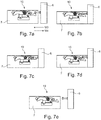
Figur 7 a) bis e) : einen Ablauf beim Montieren des Frontbauteils an ein Seitenbauteil mit der Verriegelungseinheit gemäßFigur 5 und den Ablauf bei einem anschließenden Lösen der Verriegelungseinheit, gemäßFigur 5 , und Abnehmen des Frontbauteils. - Ein erfindungsgemäßes Möbel 1 mit einem kastenförmigen Möbelkorpus 2 und einer über Führungsmittel 3 beweglich geführten Schublade 4 ist in
Figur 1 dargestellt. Die Schublade 4 ist in einer geöffneten Position relativ zum Möbelkorpus 2 dargestellt. Die Schublade 4 umfasst beispielsweise einen Schubladenboden 5, ein Frontbauteil 6, zwei gegenüberliegende Seitenbauteile 7 und eine Schubladenrückwand 8. Für eine Führung der Schublade 4 sind zwei gleichwirkende Führungsmittel 3 jeweils zwischen jedem Seitenbauteil 7 der Schublade 4 und einer dazugehörigen Korpusseitenwand 9 vorhanden. Die Schublade 4 ist über die Führungsmittel 3 am Möbelkorpus 2 in eine Öffnungsrichtung M1 und in eine Schließrichtung M2 verschiebbar gelagert. Die Führungsmittel 3 umfassen beispielsweise zwei gleichartige Teil- oder Vollauszüge. -
Figur 2 zeigt eine erfindungsgemäße Vorrichtung 10. Die Vorrichtung 10 ist im eingebauten Zustand am Seitenbauteil 7 gezeigt. Die Vorrichtung 10 umfasst eine Verriegelungseinheit 11, ein Befestigungselement 12, ein Federelement 13 und ein Verriegelungsorgan 14. Vorzugsweise ist die Verriegelungseinheit 11 über das Federelement 13 und eine Schwenkaufnahme 19 an dem Befestigungselement 12, insbesondere beweglich angebracht. Das Federelement 13 besitzt zum Beispiel eine Federkraft. Bevorzugterweise weist die Schwenkaufnahme 19 eine Schwenkachse S auf. Insbesondere ist die Schwenkachse S senkrecht zur Bewegungsebene der Schwenkaufnahme 19 ausgerichtet. - Beispielsweise umfasst die Verriegelungseinheit 11 ein Lagerelement 15, ein Verriegelungselement 16 und ein Stellelement 17.
- Bevorzugterweise ist am Frontbauteil 6 das Verriegelungsorgan 14 abstehend anordenbar. Das Verriegelungsorgan 14 umfasst in einer vorteilhaften Ausführungsform einen Kopf-Abschnitt 23 und einen Stift-Abschnitt 24. Vorzugsweise sind die Abmessungen des Verriegelungsorgans 14 so gewählt, dass es mit einem Haken-Element 21 am Verriegelungselement 16 zusammenwirken kann.
- In einer bevorzugten Ausführungsvariante ist das Haken-Element 21 gebogen, beispielsweise U-förmig. Das Haken-Element 21 umfasst, insbesondere in der U-Form, mehrere voneinander beabstandete, beispielsweise genau zwei, gegenüberliegende Flächen 27. In einer bevorzugten Variante bilden diese Flächen 27 die beiden Seiten der U-Form. Beispielsweise bilden die Flächen 27 zusammen mit einem Verbindungssteg 28 das Haken-Element 21. Der Verbindungssteg 28 des Haken-Elements 21 weist zum Beispiel eine Länge auf. Bevorzugt entspricht die Länge des Verbindungsstegs dem Abstand der beiden Flächen 27 des Haken-Elements 21. Beispielsweise ist der Abstand der Flächen 27 des Haken-Elements 21 auf die Abmessungen des Verriegelungsorgans 14 abgestimmt.
- Vorzugsweise sind die Flächen 27 des Haken-Elements 21 annähernd rechteckig. In einer Ausführungsform weisen die Flächen 27 eine abgeschrägte Seite in Form von beispielsweise einer Schräge auf. Die Flächen 27 des Haken-Elements 21 haben zum Beispiel die Form eines unregelmäßigen Fünfecks.
- Bevorzugt sind die Flächen 27 gleich ausgeführt. Vorteilhafterweise sind die Flächen 27 in einer Seitenansicht in Richtung der Schwenkachse S durch die Schwenkaufnahme 19 deckungsgleich. Vorzugsweise befinden sich die Schrägen an der Seite des Haken-Elements 21, welche im montierten Zustand dem Verriegelungsorgan 14 und dem Frontbauteil 6 zugewandt ist.
- Vorteilhafterweise sind der Kopf-Abschnitt 23 und der Stift-Abschnitt 24 des Verriegelungsorgans annähernd zylinderförmig ausgeführt. In einer bevorzugten Ausführungsform ist der Stift-Abschnitt 24 abstehend vom Frontbauteil 6 ausgebildet. Insbesondere steht der Stift-Abschnitt 24 senkrecht vom Frontbauteil 6 ab. An den Stift-Abschnitt 24 schließt sich der Kopf-Abschnitt 23 an. Der Kopf-Abschnitt 23 ist über den Stift-Abschnitt 24 vom Frontbauteil 6 beabstandet. Bevorzugt weisen der Kopf-Abschnitt 23 und der Stift-Abschnitt 24 jeweils einen Durchmesser auf. Vorzugsweise ist der Durchmesser des KopfAbschnitts 23 größer als der Durchmesser des Stift-Abschnitts 24 des Verriegelungsorgans 14.
- In einer vorteilhaften Ausführungsvariante wird die Verriegelungseinheit 11 durch das Federelement 13 in eine Ruheposition, wie in
Figur 2 dargestellt, gebracht. Beispielsweise ist das Federelement 13 mit einem Ende unmittelbar am Befestigungselement 12 angebracht. Weiter bevorzugt ist das Federelement 13 mit einem weiteren Ende unmittelbar am Lagerelement 15 angebracht. Vorteilhafterweise ist das Federelement 13 als eine Druckfeder, z.B. eine Schraubenfeder ausgebildet. Beispielsweise weist das Federelement 13 eine Höhe H auf. Insbesondere ist die Höhe H die Länge des Federelements 13 im Ruhezustand. Vorteilhafterweise ist das Federelement 13 im Ruhezustand nicht mit einer Kraft beaufschlagt, insbesondere nicht zusammengedrückt oder gedehnt. - Bevorzugt ist die Höhe H der Schraubenfeder des Federelements 13 an eine Höhe H' der Schwenkaufnahme 19 angepasst. Vorteilhafterweise sind die Höhe H des Federelements 13 und die Höhe H' der Schwenkaufnahme 19 so gewählt, dass die Verriegelungseinheit 11 z.B. annähernd parallel, insbesondere parallel zum Befestigungselement 12 angeordnet ist.
- Eine Montage des Frontbauteils 6 an das Seitenbauteil 7 erfolgt in eine Richtung M3. Bevorzugt wird das Frontbauteil 6 bei der Montage zum Seitenbauteil 7 hin bewegt. Insbesondere erfolgt ein Aufschieben des Verriegelungsorgans 14 auf das Verriegelungselement 16 in Richtung M3.
- Eine Demontage des Seitenbauteils 7 und des Frontbauteils 6 erfolgt in eine Richtung M4. Die Richtung M4 ist entgegengesetzt zur Richtung M3 ausgebildet. Insbesondere wird das Verriegelungsorgan 14 vom Verriegelungselement 16 in Richtung M4 wegbewegt.
- In den
Figuren 3 a) bis 3 c) ist die Verriegelungseinheit 11 gezeigt. InFigur 3 a) ist die Verriegelungseinheit 11 im zusammengebauten Zustand dargestellt. Die beiden weiteren DarstellungenFigur 3 b) und Figur 3 c) zeigen jeweils eine Explosionsdarstellung der Verriegelungseinheit 11 in unterschiedlicher Ansicht. InFigur 3 b) sind die Bauteile der Verriegelungseinheit 11 in einer Ansicht gezeigt, die einer Draufsicht ausFigur 2 entspricht. InFigur 3 c) sind die zur Ansicht 3 b) gegenüberliegenden Seiten sichtbar. - Beispielsweise umfasst die Verriegelungseinheit 11 in der Ausführungsform gemäß
Figur 3 ein Lagerelement 15, ein Verriegelungselement 16 und ein Stellelement 17. Vorteilhafterweise ist das Stellelement 17 als eine Scheibe, insbesondere eine kreisförmige Scheibe ausgebildet. Das Stellelement 17 als Scheibe umfasst beispielsweise zwei Seiten, insbesondere zwei gegenüberliegende Seiten der Scheibe. Zum Beispiel ist das Stellelement 17 beweglich, insbesondere drehbar am Lagerelement 15 aufgenommen. - Bevorzugt weist das in
Figur 3 b) gezeigte Stellelement 17 eine Führungskontur 18 auf. Insbesondere ist die Führungskontur 18 als eine stegförmige, von der Oberfläche erhabene, Kontur ausgebildet. Vorteilhafterweise ist an dem Stellelement 17 auch eine Eingreifmöglichkeit 22 für einen Schraubendreher angeordnet. Bevorzugt ist die Führungskontur 18 auf einer Seite des Stellelements 17 angeordnet und die Eingreifmöglichkeit 22 auf einer gegenüberliegenden Seite. - Beispielsweise ist das Verriegelungselement 16 über eine oder mehrere Durchführungen 25 des Lagerelements 15 am Lagerelement 15 geführt. Weiter umfasst das Verriegelungselement 16 z.B. eine Eingreifstruktur 20 und das Haken-Element 21. Bevorzugt ist die Führungskontur 18 des Stellelements 17 in ihren Abmessungen auf die Eingreifstruktur 20 des Verriegelungselements 16 abgestimmt. Beispielsweise ist die Führungskontur 18 als Spiralkontur ausgebildet. Vorteilhafterweise ergibt sich zusammen mit der Eingreifstruktur 20, z.B. ausgebildet als Nocken, ein Schneckentrieb. Beispielsweise bilden das Stellelement 17 mit der Führungskontur 18 und die Eingreifstruktur 20 des Verriegelungselements 16 eine Rückstelleinrichtung.
- Bevorzugterweise ist die Schwenkaufnahme 19 einstückig am Lagerelement 15 ausgebildet.
- Die
Figuren 4 a) bis c) zeigen einen beispielhaften Ablauf bei der Montage (Richtung M3) des Frontbauteils 6 an das Seitenbauteil 7. Weiter ist in denFiguren 4 d) und e) die Demontage (Richtung M4) des Frontbauteils 6 und des Seitenbauteils 7 gezeigt. - Vorteilhafterweise wird beim Aufschieben des Frontbauteils 6 mit dem Verriegelungsorgan 14 das Haken-Element 21 des Verriegelungselements 16 durch das Verriegelungsorgan 14 bewegt, insbesondere nach unten gedrückt (siehe
Figur 4 a) ), in eine Richtung hin zum Befestigungselement 12. Beispielsweise erfolgt dies gegen die Federkraft des Federelements 13 und um die Schwenkachse S der Schwenkaufnahme 19. Ist das Frontbauteil 6, vorteilhafterweise, so weit aufgeschoben, dass der Kopf-Abschnitt 23 des Verriegelungsorgans 14 sich in Richtung M3 hinter dem Haken-Element 21 befindet (sieheFigur 4 b) ), wird die Verriegelungseinheit 11 durch das Federelement 13, z.B. eine Schraubenfeder weg vom Befestigungselement 12, insbesondere nach oben gedrückt. Beispielsweise weist der Stift-Abschnitt 24 des Verriegelungsorgans 14 einen geringeren Durchmesser auf, als der Kopf-Abschnitt 23. Vorteilhafterweise umgreift das Haken-Element 21 den Stift-Abschnitt 24 von drei Seiten (sieheFigur 4 c) ). Insbesondere hintergreift das Haken-Element 21 den Kopf-Abschnitt 23 des Verriegelungsorgans 14. Bevorzugt ist über den Schneckentrieb ein Heranziehen des Frontbauteils 6 an das Seitenbauteil 7 möglich. Hierzu ist zum Beispiel mit einem Schraubdreher in die Eingreifmöglichkeit 22 einzugreifen und in die entsprechende Richtung zu drehen, so dass das Verriegelungselement 16 in Richtung M3 bewegt wird und eine Kraft auf den Kopf-Abschnitt 23 wirkt. - Vorteilhafterweise erfolgt die Demontage des Frontbauteils 6 in Richtung M4. Insbesondere ist durch ein Drehen der Eingreifmöglichkeit 22 am Stellelement 17 das Verriegelungselement 16 vom Verriegelungsorgan 14 wegbewegbar (siehe
Figur 4 d) ). Bevorzugt ist das Haken-Element 21 über das Stellelement 17 und die Eingreifstruktur 20 auf dem Verriegelungselement 16 vom Verriegelungsorgan 14 wegschwenkbar. Bevorzugt erfolgt die Bewegung des Verriegelungselements 16 gegen die Federkraft des Federelements 13. Das Verriegelungsorgan 14 ist frei und das Frontbauteil 6 ist abnehmbar (sieheFigur 4 e) ). - In den
Figuren 5 bis 7 ist eine weitere Ausführungsform der Vorrichtung 10 gezeigt. Zum leichteren Verständnis sind für sich entsprechende Teile die gleiche Bezugszeichen verwendet. - In
Figur 5 ist eine Variante der Vorrichtung 10 im eingebauten Zustand am Seitenbauteil 7 gezeigt. Beispielsweise ist am Frontbauteil 6 das Verriegelungsorgan 14 abstehend angeordnet. Die Vorrichtung 10 umfasst die Verriegelungseinheit lla, das Befestigungselement 12, das Federelement 13 und das Verriegelungsorgan 14. Weiter umfasst die Verriegelungseinheit 11a das Lagerelement 15a, das Verriegelungselement 16 und das Stellelement 17. Das Stellelement 17 ist beweglich, insbesondere drehbar am Lagerelement 15a aufgenommen. - In einer bevorzugten Ausführungsform weist die Verriegelungseinheit 11a gemäß
Figur 5 eine Bedienmöglichkeit 26 am Lagerelement 15a auf. Vorteilhafterweise ist über diese Bedienmöglichkeit 26 das Lagerelement 15a bewegbar, vorzugsweise schwenkbar, bezogen auf die Schwenkachse S der Schwenkaufnahme 19. Vorteilhafterweise ist die Bedienmöglichkeit 26 an einem Ende des Lagerelements 15a angebracht. Bevorzugt ist die Bedienmöglichkeit 26 an dem Ende des Lagerelements 15a angeordnet welches gegenüberliegend zum Haken-Element 21 ist. - Wie in
Figur 6 a) dargestellt, umfasst die Verriegelungseinheit 11a zum Beispiel das Verriegelungselement 16 mit dem Haken-Element 21. Das Haken-Element 21 ist an einem Ende des Verriegelungselements 16 angebracht. Bevorzugt ist am Lagerelement 15a die Schwenkaufnahme 19 angeordnet, insbesondere unlösbar mit dem Lagerelement 15a verbunden, z.B. einstückig. -
Figur 6 b) zeigt eine Explosionsdarstellung der Verriegelungseinheit 11a. Die Verriegelungseinheit 11a umfasst bevorzugt das Stellelement 17 mit der Führungskontur 18, welche insbesondere als Spiralkontur ausgebildet ist. - In
Figur 6 c) ist eine zuFigur 6 b) gedrehte Ansicht gezeigt. InFigur 6 c) ist z.B. die Eingreifmöglichkeit 22 am Stellelement 17 und eine Haltefläche 29 am Lagerelement 15a gezeigt. Das Lagerelement 15a umfasst vorteilhafterweise mehrere, insbesondere vier Halteflächen 29. Bevorzugt ist am Verriegelungselement 16 die Eingreifstruktur 20 angeordnet, insbesondere aus dem Material des Verriegelungselement 16 ausgebogen. - In den
Figuren 7 a) bis 7 c) ist der Ablauf der Montage (Richtung M3) des Frontbauteils 6 auf das Seitenbauteil 7 gezeigt. Die Demontage des Frontbauteils 6 vom Seitenbauteil 7 erfolgt in Richtung M4, gezeigt in denFiguren 7 d) und 7 e) . Vorteilhafterweise sind die Richtungen von M3 und M4 entgegengesetzt. - In der gezeigten Ausführung wird zuerst das Haken-Element 21 durch das Verriegelungsorgan 14 gegen die Federkraft des Federelements 13 herunter gedrückt, insbesondere in Richtung des Befestigungselements 12. Bevorzugt bewegt sich der Kopf-Abschnitt 23 des Verriegelungsorgans 14 über das Haken-Element 21 hinweg (siehe
Figur 7a )). Vorzugsweise umgreift das Haken-Element 21 den Stift-Abschnitt 24 des Verriegelungsorgans 14 (sieheFigur 7 b) ). - Bevorzugterweise befindet sich die Verriegelungseinheit 11 wieder in Ruheposition, siehe
Figur 7 c) . - Vorzugsweise ist durch ein Bewegen der Führungskontur 18 das Verriegelungselement 11a linear bewegbar. Die Führungskontur 18 ist beispielsweise am Stellelement 17 angeordnet. Bevorzugt ist die Eingreifmöglichkeit 20 auch am Stellelement 17 angeordnet. Vorteilhafterweise ist das Stellelement 17 durch den Eingriff eines Schraubendrehers in die Eingreifmöglichkeit 20 bewegbar, insbesondere drehbar. Beispielsweise kann das Frontbauteil 6 näher an das Seitenbauteil 7 herangezogen werden, indem das Stellelement 17 bewegt wird.
- Soll beispielsweise das Frontbauteil 6 wieder demontiert werden, muss zuerst das Haken-Element 21 vom Kopf-Abschnitt 23 des Verriegelungsorgans 14 gelöst werden. Vorteilhafterweise ist durch ein Drehen des Stellelements 17 die Führungskontur 18 bewegbar, so dass sich das Haken-Element 21 am Verriegelungselement 16 vom Verriegelungsorgan 14 wegbewegt. Zum Beispiel über ein Eingreifen z.B. mittels Schraubendreher an der Bedienmöglichkeit 26 ist das Lagerelement 15a gegen die Kraft des Federelements 13 wegschwenkbar (siehe
Figur 7d )). Das Verriegelungsorgan 14 ist frei und das Frontbauteil 6 abnehmbar (sieheFigur 7e )). -
- 1
- Möbel
- 2
- Möbelkorpus
- 3
- Führungsmittel
- 4
- Bewegbares Möbelteil
- 5
- Schubladenboden
- 6
- Frontbauteil
- 7
- Seitenbauteil
- 8
- Schubladenrückwand
- 9
- Korpusseitenwand
- 10
- Vorrichtung
- 11
- Verriegelungseinheit
- 11a
- Verriegelungseinheit
- 12
- Befestigungselement
- 13
- Federelement
- 14
- Verriegelungsorgan
- 15
- Lagerelement
- 15a
- Lagerelement
- 16
- Verriegelungselement
- 17
- Stellelement
- 18
- Führungskontur
- 19
- Schwenkaufnahme
- 20
- Eingreifstruktur
- 21
- Haken-Element
- 22
- Eingreifmöglichkeit
- 23
- Kopf-Abschnitt
- 24
- Stift-Abschnitt
- 25
- Durchführung
- 26
- Bedienmöglichkeit
- 27
- Fläche
- 28
- Verbindungssteg
- 29
- Haltefläche
Claims (10)
- Vorrichtung (10) zum Verbinden eines Frontbauteils (6) eines bewegbaren Möbelteils (4) mit einem Seitenbauteil (7) des bewegbaren Möbelteils (4),
wobei die Vorrichtung (10) dazu ausgebildet ist, am Seitenbauteil (7) des bewegbaren Möbelteils (4) befestigt zu werden,
wobei die Vorrichtung (10) eine Verriegelungseinheit (11, 11a), ein Befestigungselement (12), ein Federelement (13) und ein Verriegelungsorgan (14) aufweist,
wobei die Verriegelungseinheit (11, 11a), ein Verriegelungselement (16) umfasst,
wobei das Befestigungselement (12) dazu ausgebildet ist, positionsfest am Seitenbauteil (7) angeordnet zu werden,
wobei die Verriegelungseinheit (11, 11a) um eine Schwenkachse schwenkbeweglich am Befestigungselement (12) gelagert ist,
wobei das Verriegelungsorgan (14) dazu ausgebildet ist, am Frontbauteil (6) angeordnet zu werden,
wobei das Verriegelungselement (16) mit dem Verriegelungsorgan (14) im angeordneten Zustand am bewegbaren Möbelteil (4) verriegelbar ist,
wobei das Verriegelungselement (16) durch das Federelement (13) kraftbeaufschlagt vorhanden ist, sodass das Verriegelungselement (16) bei einem Verriegelungsvorgang mit dem Verriegelungsorgan (14) gegen eine Kraft des Federelements (13) um die Schwenkachse schwenkbar ist,
wobei die Verriegelungseinheit (11, 11a) ein Lagerelement (15, 15a) und eine Rückstelleinrichtung aufweist,
wobei das Verriegelungselement (16) am Lagerelement (15, 15a) linear verschieblich gelagert ist,
wobei mittels der Rückstelleinrichtung das Verriegelungselement (16) relativ zum Lagerelement (15, 15a) bewegbar ist. - Vorrichtung (10) nach Anspruch 1, dadurch gekennzeichnet, dass das Lagerelement (15, 15a) über eine Schwenkaufnahme (19) am Befestigungselement (12) angebracht ist.
- Vorrichtung (10) nach einem der vorhergehenden Ansprüche, dadurch gekennzeichnet, dass die Verbindung zwischen dem Frontbauteil (6) und dem Seitenbauteil (7) in zwei Stufen erfolgen kann, wobei in einer ersten Stufe das Verriegelungselement (16) und das Verriegelungsorgan (14) durch ein Hinterschnappen des Verriegelungselements (16) mit dem Verriegelungsorgan (14) verbunden wird und in einer zweiten Stufe das Verriegelungselement (16) über die Rückstelleinrichtung relativ zum Lagerelement (15, 15a) bewegbar ist, so dass sich der Abstand zwischen Frontbauteil (6) und Seitenbauteil (7) verringern lässt.
- Vorrichtung (10) nach einem der vorhergehenden Ansprüche, dadurch gekennzeichnet, dass die Rückstelleinrichtung als ein Schneckentrieb oder ein Exzentertrieb ausgebildet ist.
- Vorrichtung (10) nach einem der vorhergehenden Ansprüche, dadurch gekennzeichnet, dass ein Stellelement (17) der Rückstelleinrichtung drehbar in dem Lagerelement (15, 15a) aufgenommen ist und mit Nocken (20) auf dem Verriegelungselement (16) zusammenwirkt.
- Vorrichtung (10) nach einem der vorhergehenden Ansprüche, dadurch gekennzeichnet, dass ein Entriegelungsmechanismus vorgesehen ist, mit welchem das Verriegelungselement (16) von dem Verriegelungsorgan (14) weggeschenkt werden kann, so dass das Verriegelungsorgan (14) freigegeben wird.
- Vorrichtung (10) nach einem der vorhergehenden Ansprüche, dadurch gekennzeichnet, dass das Wegschwenken des Verriegelungselements (16) durch den Entriegelungsmechanismus gegen die Kraft des Federelements (13) erfolgt.
- Vorrichtung (10) nach einem der vorhergehenden Ansprüche, dadurch gekennzeichnet, dass das Wegschwenken des Verriegelungselements (16) durch den Entriegelungsmechanismus über den Schneckentrieb erfolgt.
- Seitenbauteil (7), insbesondere Schubladenseitenwand, mit einer Vorrichtung (10) nach einem der vorhergehenden Ansprüche.
- Möbel (1), insbesondere Schublade mit einer Vorrichtung (10) nach einem der vorhergehenden Ansprüche.
Applications Claiming Priority (1)
| Application Number | Priority Date | Filing Date | Title |
|---|---|---|---|
| DE102019128034.6A DE102019128034A1 (de) | 2019-10-17 | 2019-10-17 | Vorrichtung zum Verbinden eines Frontbauteils eines bewegbaren Möbelteils mit einem Seitenbauteil des bewegbaren Möbelteils |
Publications (2)
| Publication Number | Publication Date |
|---|---|
| EP3808217A1 true EP3808217A1 (de) | 2021-04-21 |
| EP3808217B1 EP3808217B1 (de) | 2024-01-17 |
Family
ID=72717790
Family Applications (1)
| Application Number | Title | Priority Date | Filing Date |
|---|---|---|---|
| EP20199655.0A Active EP3808217B1 (de) | 2019-10-17 | 2020-10-01 | Vorrichtung zum verbinden eines frontbauteils eines bewegbaren möbelteils mit einem seitenbauteil des bewegbaren möbelteils |
Country Status (3)
| Country | Link |
|---|---|
| EP (1) | EP3808217B1 (de) |
| DE (1) | DE102019128034A1 (de) |
| ES (1) | ES2977488T3 (de) |
Citations (2)
| Publication number | Priority date | Publication date | Assignee | Title |
|---|---|---|---|---|
| CN102334848A (zh) * | 2011-09-30 | 2012-02-01 | 广东中侨五金电器制造有限公司 | 抽屉侧板连接及调节装置 |
| CN106820676A (zh) * | 2015-12-03 | 2017-06-13 | 川湖科技股份有限公司 | 安装机构 |
Family Cites Families (3)
| Publication number | Priority date | Publication date | Assignee | Title |
|---|---|---|---|---|
| DE3047642A1 (de) * | 1980-12-17 | 1982-10-28 | Arturo Salice S.p.A., 22060 Novedrate, Como | Verbindungsbeschlag |
| AT399261B (de) * | 1991-04-02 | 1995-04-25 | Blum Gmbh Julius | Frontblendenhalterung für schubladen |
| DE202007015212U1 (de) * | 2007-11-02 | 2008-01-24 | Anton Schneider Gmbh & Co Kg | Befestigungsvorrichtung für Möbelteile |
-
2019
- 2019-10-17 DE DE102019128034.6A patent/DE102019128034A1/de active Pending
-
2020
- 2020-10-01 ES ES20199655T patent/ES2977488T3/es active Active
- 2020-10-01 EP EP20199655.0A patent/EP3808217B1/de active Active
Patent Citations (2)
| Publication number | Priority date | Publication date | Assignee | Title |
|---|---|---|---|---|
| CN102334848A (zh) * | 2011-09-30 | 2012-02-01 | 广东中侨五金电器制造有限公司 | 抽屉侧板连接及调节装置 |
| CN106820676A (zh) * | 2015-12-03 | 2017-06-13 | 川湖科技股份有限公司 | 安装机构 |
Also Published As
| Publication number | Publication date |
|---|---|
| DE102019128034A1 (de) | 2021-04-22 |
| ES2977488T3 (es) | 2024-08-26 |
| EP3808217B1 (de) | 2024-01-17 |
Similar Documents
| Publication | Publication Date | Title |
|---|---|---|
| EP3973126B1 (de) | Möbelbeschlag | |
| EP2961899B1 (de) | Betätigungshandhabe | |
| WO2020236101A1 (de) | Beschlaganordnung | |
| WO2000073026A2 (de) | Exzenterspannzwinge | |
| EP3973131A1 (de) | Möbelbeschlag | |
| DE10233766B4 (de) | Ratsche | |
| EP1050378A2 (de) | "Wasserpumpenzange mit Einhandbedienung" | |
| WO2018204956A1 (de) | Möbelantrieb | |
| EP3621483A1 (de) | Haltevorrichtung für eine frontblende einer schublade | |
| EP3411547B1 (de) | Vorreiberverschluss mit einem in unterschiedlicher höhe an einer schliesswelle fixierbaren verschlusselement | |
| EP3621484B1 (de) | Haltevorrichtung für eine frontblende einer schublade | |
| EP3568239A2 (de) | Kartuschenpresse | |
| DE202009016669U1 (de) | Möbel, Möbelteil und Vorrichtung zur Verbindung eines Frontbauteils eines Möbelteils | |
| EP3808217B1 (de) | Vorrichtung zum verbinden eines frontbauteils eines bewegbaren möbelteils mit einem seitenbauteil des bewegbaren möbelteils | |
| EP2233039B1 (de) | Schubkastenführung | |
| EP2578891B1 (de) | Adapter | |
| EP3701836B1 (de) | Vorrichtung zur verbindung eines frontelements mit einem seitenteil eines bewegbaren möbelteils | |
| DE102017125609B3 (de) | Bandteil | |
| DE4122753A1 (de) | Gripzange | |
| DE102006013361A1 (de) | Verriegelung für Tischtennis-Tische mit verschwenkbaren Plattenhälften | |
| DE102020126347B3 (de) | Abstandhalter, Führungsschiene für einen Raffstore oder eine Jalousie sowie Raffstore und Jalousie und Verfahren hierfür | |
| EP1158184B1 (de) | Halterung zur Fixierung eines Gegenstandes, insbesondere einer Leuchte | |
| DE102004011054B4 (de) | Ratschenartige Verstellvorrichtung | |
| EP1816009B1 (de) | Verschlussmechanik für gelochte, lose Blätter | |
| DE10120985B4 (de) | Klappmesser |
Legal Events
| Date | Code | Title | Description |
|---|---|---|---|
| PUAI | Public reference made under article 153(3) epc to a published international application that has entered the european phase |
Free format text: ORIGINAL CODE: 0009012 |
|
| STAA | Information on the status of an ep patent application or granted ep patent |
Free format text: STATUS: THE APPLICATION HAS BEEN PUBLISHED |
|
| AK | Designated contracting states |
Kind code of ref document: A1 Designated state(s): AL AT BE BG CH CY CZ DE DK EE ES FI FR GB GR HR HU IE IS IT LI LT LU LV MC MK MT NL NO PL PT RO RS SE SI SK SM TR |
|
| AX | Request for extension of the european patent |
Extension state: BA ME |
|
| STAA | Information on the status of an ep patent application or granted ep patent |
Free format text: STATUS: REQUEST FOR EXAMINATION WAS MADE |
|
| 17P | Request for examination filed |
Effective date: 20211006 |
|
| RBV | Designated contracting states (corrected) |
Designated state(s): AL AT BE BG CH CY CZ DE DK EE ES FI FR GB GR HR HU IE IS IT LI LT LU LV MC MK MT NL NO PL PT RO RS SE SI SK SM TR |
|
| GRAP | Despatch of communication of intention to grant a patent |
Free format text: ORIGINAL CODE: EPIDOSNIGR1 |
|
| STAA | Information on the status of an ep patent application or granted ep patent |
Free format text: STATUS: GRANT OF PATENT IS INTENDED |
|
| INTG | Intention to grant announced |
Effective date: 20230418 |
|
| GRAJ | Information related to disapproval of communication of intention to grant by the applicant or resumption of examination proceedings by the epo deleted |
Free format text: ORIGINAL CODE: EPIDOSDIGR1 |
|
| STAA | Information on the status of an ep patent application or granted ep patent |
Free format text: STATUS: REQUEST FOR EXAMINATION WAS MADE |
|
| GRAP | Despatch of communication of intention to grant a patent |
Free format text: ORIGINAL CODE: EPIDOSNIGR1 |
|
| STAA | Information on the status of an ep patent application or granted ep patent |
Free format text: STATUS: GRANT OF PATENT IS INTENDED |
|
| INTC | Intention to grant announced (deleted) | ||
| INTG | Intention to grant announced |
Effective date: 20230811 |
|
| GRAS | Grant fee paid |
Free format text: ORIGINAL CODE: EPIDOSNIGR3 |
|
| GRAA | (expected) grant |
Free format text: ORIGINAL CODE: 0009210 |
|
| STAA | Information on the status of an ep patent application or granted ep patent |
Free format text: STATUS: THE PATENT HAS BEEN GRANTED |
|
| AK | Designated contracting states |
Kind code of ref document: B1 Designated state(s): AL AT BE BG CH CY CZ DE DK EE ES FI FR GB GR HR HU IE IS IT LI LT LU LV MC MK MT NL NO PL PT RO RS SE SI SK SM TR |
|
| REG | Reference to a national code |
Ref country code: GB Ref legal event code: FG4D Free format text: NOT ENGLISH |
|
| REG | Reference to a national code |
Ref country code: DE Ref legal event code: R096 Ref document number: 502020006742 Country of ref document: DE |
|
| REG | Reference to a national code |
Ref country code: CH Ref legal event code: EP |
|
| REG | Reference to a national code |
Ref country code: IE Ref legal event code: FG4D Free format text: LANGUAGE OF EP DOCUMENT: GERMAN |
|
| REG | Reference to a national code |
Ref country code: LT Ref legal event code: MG9D |
|
| REG | Reference to a national code |
Ref country code: NL Ref legal event code: MP Effective date: 20240117 |
|
| PG25 | Lapsed in a contracting state [announced via postgrant information from national office to epo] |
Ref country code: NL Free format text: LAPSE BECAUSE OF FAILURE TO SUBMIT A TRANSLATION OF THE DESCRIPTION OR TO PAY THE FEE WITHIN THE PRESCRIBED TIME-LIMIT Effective date: 20240117 |
|
| PG25 | Lapsed in a contracting state [announced via postgrant information from national office to epo] |
Ref country code: NL Free format text: LAPSE BECAUSE OF FAILURE TO SUBMIT A TRANSLATION OF THE DESCRIPTION OR TO PAY THE FEE WITHIN THE PRESCRIBED TIME-LIMIT Effective date: 20240117 |
|
| PG25 | Lapsed in a contracting state [announced via postgrant information from national office to epo] |
Ref country code: IS Free format text: LAPSE BECAUSE OF FAILURE TO SUBMIT A TRANSLATION OF THE DESCRIPTION OR TO PAY THE FEE WITHIN THE PRESCRIBED TIME-LIMIT Effective date: 20240517 |
|
| PG25 | Lapsed in a contracting state [announced via postgrant information from national office to epo] |
Ref country code: LT Free format text: LAPSE BECAUSE OF FAILURE TO SUBMIT A TRANSLATION OF THE DESCRIPTION OR TO PAY THE FEE WITHIN THE PRESCRIBED TIME-LIMIT Effective date: 20240117 |
|
| PG25 | Lapsed in a contracting state [announced via postgrant information from national office to epo] |
Ref country code: GR Free format text: LAPSE BECAUSE OF FAILURE TO SUBMIT A TRANSLATION OF THE DESCRIPTION OR TO PAY THE FEE WITHIN THE PRESCRIBED TIME-LIMIT Effective date: 20240418 |
|
| PG25 | Lapsed in a contracting state [announced via postgrant information from national office to epo] |
Ref country code: HR Free format text: LAPSE BECAUSE OF FAILURE TO SUBMIT A TRANSLATION OF THE DESCRIPTION OR TO PAY THE FEE WITHIN THE PRESCRIBED TIME-LIMIT Effective date: 20240117 Ref country code: RS Free format text: LAPSE BECAUSE OF FAILURE TO SUBMIT A TRANSLATION OF THE DESCRIPTION OR TO PAY THE FEE WITHIN THE PRESCRIBED TIME-LIMIT Effective date: 20240417 |
|
| PG25 | Lapsed in a contracting state [announced via postgrant information from national office to epo] |
Ref country code: RS Free format text: LAPSE BECAUSE OF FAILURE TO SUBMIT A TRANSLATION OF THE DESCRIPTION OR TO PAY THE FEE WITHIN THE PRESCRIBED TIME-LIMIT Effective date: 20240417 Ref country code: NO Free format text: LAPSE BECAUSE OF FAILURE TO SUBMIT A TRANSLATION OF THE DESCRIPTION OR TO PAY THE FEE WITHIN THE PRESCRIBED TIME-LIMIT Effective date: 20240417 Ref country code: LT Free format text: LAPSE BECAUSE OF FAILURE TO SUBMIT A TRANSLATION OF THE DESCRIPTION OR TO PAY THE FEE WITHIN THE PRESCRIBED TIME-LIMIT Effective date: 20240117 Ref country code: IS Free format text: LAPSE BECAUSE OF FAILURE TO SUBMIT A TRANSLATION OF THE DESCRIPTION OR TO PAY THE FEE WITHIN THE PRESCRIBED TIME-LIMIT Effective date: 20240517 Ref country code: HR Free format text: LAPSE BECAUSE OF FAILURE TO SUBMIT A TRANSLATION OF THE DESCRIPTION OR TO PAY THE FEE WITHIN THE PRESCRIBED TIME-LIMIT Effective date: 20240117 Ref country code: GR Free format text: LAPSE BECAUSE OF FAILURE TO SUBMIT A TRANSLATION OF THE DESCRIPTION OR TO PAY THE FEE WITHIN THE PRESCRIBED TIME-LIMIT Effective date: 20240418 Ref country code: FI Free format text: LAPSE BECAUSE OF FAILURE TO SUBMIT A TRANSLATION OF THE DESCRIPTION OR TO PAY THE FEE WITHIN THE PRESCRIBED TIME-LIMIT Effective date: 20240117 Ref country code: BG Free format text: LAPSE BECAUSE OF FAILURE TO SUBMIT A TRANSLATION OF THE DESCRIPTION OR TO PAY THE FEE WITHIN THE PRESCRIBED TIME-LIMIT Effective date: 20240117 |
|
| PG25 | Lapsed in a contracting state [announced via postgrant information from national office to epo] |
Ref country code: PT Free format text: LAPSE BECAUSE OF FAILURE TO SUBMIT A TRANSLATION OF THE DESCRIPTION OR TO PAY THE FEE WITHIN THE PRESCRIBED TIME-LIMIT Effective date: 20240517 Ref country code: PL Free format text: LAPSE BECAUSE OF FAILURE TO SUBMIT A TRANSLATION OF THE DESCRIPTION OR TO PAY THE FEE WITHIN THE PRESCRIBED TIME-LIMIT Effective date: 20240117 |
|
| REG | Reference to a national code |
Ref country code: ES Ref legal event code: FG2A Ref document number: 2977488 Country of ref document: ES Kind code of ref document: T3 Effective date: 20240826 |
|
| PG25 | Lapsed in a contracting state [announced via postgrant information from national office to epo] |
Ref country code: SE Free format text: LAPSE BECAUSE OF FAILURE TO SUBMIT A TRANSLATION OF THE DESCRIPTION OR TO PAY THE FEE WITHIN THE PRESCRIBED TIME-LIMIT Effective date: 20240117 Ref country code: PT Free format text: LAPSE BECAUSE OF FAILURE TO SUBMIT A TRANSLATION OF THE DESCRIPTION OR TO PAY THE FEE WITHIN THE PRESCRIBED TIME-LIMIT Effective date: 20240517 Ref country code: PL Free format text: LAPSE BECAUSE OF FAILURE TO SUBMIT A TRANSLATION OF THE DESCRIPTION OR TO PAY THE FEE WITHIN THE PRESCRIBED TIME-LIMIT Effective date: 20240117 Ref country code: LV Free format text: LAPSE BECAUSE OF FAILURE TO SUBMIT A TRANSLATION OF THE DESCRIPTION OR TO PAY THE FEE WITHIN THE PRESCRIBED TIME-LIMIT Effective date: 20240117 |
|
| PG25 | Lapsed in a contracting state [announced via postgrant information from national office to epo] |
Ref country code: DK Free format text: LAPSE BECAUSE OF FAILURE TO SUBMIT A TRANSLATION OF THE DESCRIPTION OR TO PAY THE FEE WITHIN THE PRESCRIBED TIME-LIMIT Effective date: 20240117 |
|
| PG25 | Lapsed in a contracting state [announced via postgrant information from national office to epo] |
Ref country code: SM Free format text: LAPSE BECAUSE OF FAILURE TO SUBMIT A TRANSLATION OF THE DESCRIPTION OR TO PAY THE FEE WITHIN THE PRESCRIBED TIME-LIMIT Effective date: 20240117 |
|
| REG | Reference to a national code |
Ref country code: DE Ref legal event code: R097 Ref document number: 502020006742 Country of ref document: DE |
|
| PG25 | Lapsed in a contracting state [announced via postgrant information from national office to epo] |
Ref country code: EE Free format text: LAPSE BECAUSE OF FAILURE TO SUBMIT A TRANSLATION OF THE DESCRIPTION OR TO PAY THE FEE WITHIN THE PRESCRIBED TIME-LIMIT Effective date: 20240117 Ref country code: CZ Free format text: LAPSE BECAUSE OF FAILURE TO SUBMIT A TRANSLATION OF THE DESCRIPTION OR TO PAY THE FEE WITHIN THE PRESCRIBED TIME-LIMIT Effective date: 20240117 |
|
| PG25 | Lapsed in a contracting state [announced via postgrant information from national office to epo] |
Ref country code: SK Free format text: LAPSE BECAUSE OF FAILURE TO SUBMIT A TRANSLATION OF THE DESCRIPTION OR TO PAY THE FEE WITHIN THE PRESCRIBED TIME-LIMIT Effective date: 20240117 |
|
| PG25 | Lapsed in a contracting state [announced via postgrant information from national office to epo] |
Ref country code: SM Free format text: LAPSE BECAUSE OF FAILURE TO SUBMIT A TRANSLATION OF THE DESCRIPTION OR TO PAY THE FEE WITHIN THE PRESCRIBED TIME-LIMIT Effective date: 20240117 Ref country code: SK Free format text: LAPSE BECAUSE OF FAILURE TO SUBMIT A TRANSLATION OF THE DESCRIPTION OR TO PAY THE FEE WITHIN THE PRESCRIBED TIME-LIMIT Effective date: 20240117 Ref country code: RO Free format text: LAPSE BECAUSE OF FAILURE TO SUBMIT A TRANSLATION OF THE DESCRIPTION OR TO PAY THE FEE WITHIN THE PRESCRIBED TIME-LIMIT Effective date: 20240117 Ref country code: EE Free format text: LAPSE BECAUSE OF FAILURE TO SUBMIT A TRANSLATION OF THE DESCRIPTION OR TO PAY THE FEE WITHIN THE PRESCRIBED TIME-LIMIT Effective date: 20240117 Ref country code: DK Free format text: LAPSE BECAUSE OF FAILURE TO SUBMIT A TRANSLATION OF THE DESCRIPTION OR TO PAY THE FEE WITHIN THE PRESCRIBED TIME-LIMIT Effective date: 20240117 Ref country code: CZ Free format text: LAPSE BECAUSE OF FAILURE TO SUBMIT A TRANSLATION OF THE DESCRIPTION OR TO PAY THE FEE WITHIN THE PRESCRIBED TIME-LIMIT Effective date: 20240117 |
|
| PLBE | No opposition filed within time limit |
Free format text: ORIGINAL CODE: 0009261 |
|
| STAA | Information on the status of an ep patent application or granted ep patent |
Free format text: STATUS: NO OPPOSITION FILED WITHIN TIME LIMIT |
|
| 26N | No opposition filed |
Effective date: 20241018 |
|
| REG | Reference to a national code |
Ref country code: DE Ref legal event code: R082 Ref document number: 502020006742 Country of ref document: DE Representative=s name: RAVENSPAT PATENTANWAELTE PARTNERSCHAFT MBB, DE |
|
| PG25 | Lapsed in a contracting state [announced via postgrant information from national office to epo] |
Ref country code: SI Free format text: LAPSE BECAUSE OF FAILURE TO SUBMIT A TRANSLATION OF THE DESCRIPTION OR TO PAY THE FEE WITHIN THE PRESCRIBED TIME-LIMIT Effective date: 20240117 |
|
| REG | Reference to a national code |
Ref country code: CH Ref legal event code: PL |
|
| GBPC | Gb: european patent ceased through non-payment of renewal fee |
Effective date: 20241001 |
|
| PG25 | Lapsed in a contracting state [announced via postgrant information from national office to epo] |
Ref country code: MC Free format text: LAPSE BECAUSE OF FAILURE TO SUBMIT A TRANSLATION OF THE DESCRIPTION OR TO PAY THE FEE WITHIN THE PRESCRIBED TIME-LIMIT Effective date: 20240117 |
|
| PG25 | Lapsed in a contracting state [announced via postgrant information from national office to epo] |
Ref country code: GB Free format text: LAPSE BECAUSE OF NON-PAYMENT OF DUE FEES Effective date: 20241001 |
|
| PG25 | Lapsed in a contracting state [announced via postgrant information from national office to epo] |
Ref country code: LU Free format text: LAPSE BECAUSE OF NON-PAYMENT OF DUE FEES Effective date: 20241001 Ref country code: BE Free format text: LAPSE BECAUSE OF NON-PAYMENT OF DUE FEES Effective date: 20241031 |
|
| PG25 | Lapsed in a contracting state [announced via postgrant information from national office to epo] |
Ref country code: FR Free format text: LAPSE BECAUSE OF NON-PAYMENT OF DUE FEES Effective date: 20241031 |
|
| PG25 | Lapsed in a contracting state [announced via postgrant information from national office to epo] |
Ref country code: CH Free format text: LAPSE BECAUSE OF NON-PAYMENT OF DUE FEES Effective date: 20241031 |
|
| REG | Reference to a national code |
Ref country code: BE Ref legal event code: MM Effective date: 20241031 |
|
| PG25 | Lapsed in a contracting state [announced via postgrant information from national office to epo] |
Ref country code: IE Free format text: LAPSE BECAUSE OF NON-PAYMENT OF DUE FEES Effective date: 20241001 |
|
| PGFP | Annual fee paid to national office [announced via postgrant information from national office to epo] |
Ref country code: DE Payment date: 20251024 Year of fee payment: 6 |
|
| PGFP | Annual fee paid to national office [announced via postgrant information from national office to epo] |
Ref country code: AT Payment date: 20251027 Year of fee payment: 6 |
|
| PGFP | Annual fee paid to national office [announced via postgrant information from national office to epo] |
Ref country code: IT Payment date: 20251015 Year of fee payment: 6 |
|
| PG25 | Lapsed in a contracting state [announced via postgrant information from national office to epo] |
Ref country code: CY Free format text: LAPSE BECAUSE OF FAILURE TO SUBMIT A TRANSLATION OF THE DESCRIPTION OR TO PAY THE FEE WITHIN THE PRESCRIBED TIME-LIMIT; INVALID AB INITIO Effective date: 20201001 |
|
| PGFP | Annual fee paid to national office [announced via postgrant information from national office to epo] |
Ref country code: ES Payment date: 20251104 Year of fee payment: 6 |
|
| PG25 | Lapsed in a contracting state [announced via postgrant information from national office to epo] |
Ref country code: HU Free format text: LAPSE BECAUSE OF FAILURE TO SUBMIT A TRANSLATION OF THE DESCRIPTION OR TO PAY THE FEE WITHIN THE PRESCRIBED TIME-LIMIT; INVALID AB INITIO Effective date: 20201001 |