EP3807523B1 - Dispositif pour l'introduction de force longitudinale ou de traction ainsi que procédé pour la fabrication d'un tel dispositif - Google Patents
Dispositif pour l'introduction de force longitudinale ou de traction ainsi que procédé pour la fabrication d'un tel dispositif Download PDFInfo
- Publication number
- EP3807523B1 EP3807523B1 EP19733392.5A EP19733392A EP3807523B1 EP 3807523 B1 EP3807523 B1 EP 3807523B1 EP 19733392 A EP19733392 A EP 19733392A EP 3807523 B1 EP3807523 B1 EP 3807523B1
- Authority
- EP
- European Patent Office
- Prior art keywords
- arrangement
- component
- bolts
- transverse recesses
- bolt
- Prior art date
- Legal status (The legal status is an assumption and is not a legal conclusion. Google has not performed a legal analysis and makes no representation as to the accuracy of the status listed.)
- Active
Links
- 238000004519 manufacturing process Methods 0.000 title claims description 7
- 230000005540 biological transmission Effects 0.000 title 1
- 229920002430 Fibre-reinforced plastic Polymers 0.000 claims description 6
- 239000011151 fibre-reinforced plastic Substances 0.000 claims description 6
- 239000002131 composite material Substances 0.000 claims description 5
- 210000001503 joint Anatomy 0.000 claims description 3
- 238000000034 method Methods 0.000 description 3
- 239000007787 solid Substances 0.000 description 3
- 238000003801 milling Methods 0.000 description 2
- 238000010276 construction Methods 0.000 description 1
- 238000005553 drilling Methods 0.000 description 1
- 230000000694 effects Effects 0.000 description 1
- 239000003292 glue Substances 0.000 description 1
- 238000009434 installation Methods 0.000 description 1
- 230000001788 irregular Effects 0.000 description 1
- 239000000463 material Substances 0.000 description 1
- 230000036316 preload Effects 0.000 description 1
Images


Classifications
-
- F—MECHANICAL ENGINEERING; LIGHTING; HEATING; WEAPONS; BLASTING
- F03—MACHINES OR ENGINES FOR LIQUIDS; WIND, SPRING, OR WEIGHT MOTORS; PRODUCING MECHANICAL POWER OR A REACTIVE PROPULSIVE THRUST, NOT OTHERWISE PROVIDED FOR
- F03D—WIND MOTORS
- F03D1/00—Wind motors with rotation axis substantially parallel to the air flow entering the rotor
- F03D1/06—Rotors
- F03D1/065—Rotors characterised by their construction elements
- F03D1/0658—Arrangements for fixing wind-engaging parts to a hub
-
- Y—GENERAL TAGGING OF NEW TECHNOLOGICAL DEVELOPMENTS; GENERAL TAGGING OF CROSS-SECTIONAL TECHNOLOGIES SPANNING OVER SEVERAL SECTIONS OF THE IPC; TECHNICAL SUBJECTS COVERED BY FORMER USPC CROSS-REFERENCE ART COLLECTIONS [XRACs] AND DIGESTS
- Y02—TECHNOLOGIES OR APPLICATIONS FOR MITIGATION OR ADAPTATION AGAINST CLIMATE CHANGE
- Y02E—REDUCTION OF GREENHOUSE GAS [GHG] EMISSIONS, RELATED TO ENERGY GENERATION, TRANSMISSION OR DISTRIBUTION
- Y02E10/00—Energy generation through renewable energy sources
- Y02E10/70—Wind energy
- Y02E10/72—Wind turbines with rotation axis in wind direction
Definitions
- the present invention relates to an arrangement for introducing tensile or longitudinal forces in a component provided with transverse recesses for one fastening bolt each, with a tension bolt provided for introducing the force, comprising a first end and a second end, acting on each of the fastening bolts, as well as a method for Production of an arrangement for the introduction of tensile or longitudinal forces in a component.
- connection used therein is also referred to as a T-bolt connection or cross-bolt connection.
- the present invention is therefore based on the object of providing a connection which has a higher load-bearing capacity, with external dimensions which are in principle similar.
- this object is achieved by an arrangement for the introduction of tensile or longitudinal forces in a device provided with transverse recesses for fastening bolts Component, wherein at least one tension bolt provided for the introduction of force, comprising a first end and a second end, acts on each of the fastening bolts, wherein the or each tension bolt extends in a hole in the component and has an eyelet on at least one of its first and second ends has, through which an associated fastening bolt extends, wherein the component is a composite component or a fiber-reinforced plastic component.
- the object is achieved by a method for producing an arrangement for the introduction of tensile or longitudinal forces according to one of claims 1 to 6, comprising the steps: Providing a component with holes and transverse recesses, arranging tension bolts, each having an eyelet at at least one end, in associated holes, inserting fastening bolts into the transverse recesses and through the eyelets, and securing the fastening bolts, the component being a composite component or is a fiber-reinforced plastic component.
- the fastening bolts are secured against movement relative to the component with a securing means.
- transverse recesses are arranged next to one another in one plane.
- the transverse recesses can be arranged alternately in a number of planes offset with respect to one another.
- the holes are substantially perpendicular to the transverse recesses, preferably with each of the holes crossing an associated one of the transverse recesses.
- a ratio a/d between a distance a between the longitudinal axes of two adjacent transverse recesses and a diameter d of the transverse recesses has a value in the range between approximately 2 and approximately 3.
- the fastening bolts are expediently designed to be solid in cross section, at least at the point at which a respective tension bolt acts.
- the fastening bolts at least at the point at which a respective tension bolt acts, are designed in cross section such that they have a higher moment of inertia in the loading direction than perpendicular to the loading direction.
- the fastening bolts each comprise at least one wedge-shaped element for applying a prestressing force.
- the fastening bolt is designed in multiple parts, in particular in two or three parts.
- the tie bolt has an eyelet at only one of its first and second ends and a threaded shank at the other of its first and second ends.
- one of the first and second ends of the tie bolt can be designed as a multi-armed end, each with an eyelet through which an associated fastening bolt extends.
- the component is a composite component or a fiber-reinforced plastic component
- the component (12) is a rotor blade for a wind energy installation.
- Two or more tie bolts are expediently assigned to one of the fastening bolts.
- the invention also provides a blade connection for a rotor blade of a wind turbine for connecting the rotor blade to a connection part, in particular a rotor hub, comprising an arrangement according to claim 6, wherein the component is a rotor blade and the connection to the connection part is made by means of the tie bolts.
- the invention also provides a rotor blade for a wind turbine made from a transversely divided hollow profile with a butt joint, comprising an arrangement according to claim 6.
- the or each tension bolt has an eyelet at its first and second ends, through which an associated fastening bolt extends.
- the holes run essentially perpendicularly to the transverse recesses, preferably with each of the holes crossing an associated one of the transverse recesses.
- the holes and/or transverse recesses are advantageously produced by providing or producing grooves during manufacture of the component.
- the holes and/or transverse recesses are produced by subsequent processing, in particular by drilling and/or milling.
- the method further comprises: inserting one of the first and second ends of each tension bolt into a connection part, and connecting one of the first and second ends of each tension bolt to the connection part.
- the fastening bolts each comprise at least one wedge-shaped element for applying a prestressing force and that the method further comprises the step: moving the wedge-shaped elements in a respective associated transverse recess in a direction for applying a prestressing force to the tension bolt.
- the invention is based on the surprising finding that by adding an eyelet to one end of the tie bolt, with the outer dimensions of each tie rod remaining the same in principle, a distance between two adjacent tie rods can be significantly reduced compared to the prior art. As a result, the diameter of the transverse bolt no longer has to be larger than that of the traction device, which means that the number of traction devices per unit length and thus the load-bearing capacity of the arrangement can be significantly increased compared to the prior art.
- FIG 1 shows an arrangement 10 in a partial sectional view.
- the arrangement 10 has a component 12 which has transverse recesses 14 (in FIG figure 1 extending perpendicularly into the plane of the drawing) and holes 16 (in the figure 1 extending vertically parallel to the plane of the drawing).
- the transverse recesses 14 and the holes 16 are each arranged perpendicular to one another.
- the assembly 10 further includes mounting bolts 18, each extending in the transverse recesses 14, and tie bolts 20, having a first end 22 and a second end (not shown) and extending in the holes 16, respectively.
- the fastening bolts 18 also include a threaded bore 15 (not shown in detail) and the tie bolts 20 have a threaded shank 17 (not shown in detail).
- the tie bolts 20 are screwed with their threaded shank 17 into the threaded bores 15 of the fastening bolts 18 . Due to the required threaded bore 15, a diameter D of the fastening bolts 18 in this arrangement 10 is necessarily greater than a diameter d of the tie bolts 20. In order to ensure sufficient mechanical stability of the connection between the tie bolts 20 and the fastening bolts 18, values in the prior art are chosen from D ⁇ 2d.
- FIG. 12 shows a sectional view of the arrangement along a dashed line of FIG figure 1 . This shows how the tension bolt 20 engages in the fastening bolt 18 (T-bolt connection).
- figure 3 shows a sectional view of the special embodiment along a plane spanned by the tie bolts 20 .
- the arrangement 10 according to the invention has a component 12 which has transverse recesses 14 and holes 16 .
- the assembly 10 also includes mounting bolts 18, each extending in the transverse recesses 14, and tie bolts 20, having a first end 22 and a second end (not shown) and extending in the holes 16, respectively.
- a diameter of the transverse recesses 14 and/or the holes 16 can essentially correspond to a diameter of the fastening bolts 18 or the tie bolts 20 .
- a cross-sectional shape of the transverse recesses 14 and/or the holes 16 can essentially correspond to a cross-sectional shape of the fastening bolts 18 or the tie bolts 20 .
- the holes can also be in the form of blind holes or through-holes, for example.
- the holes and/or transverse recesses can have been produced by subsequent processing and/or by providing grooves during the manufacture of the component 12.
- the tension bolts 20 each have an eyelet 24 at their first ends 22, through which an associated fastening bolt 18 extends. One of the tension bolts 20 engages on each of the fastening bolts 18 via an eyelet 24 .
- two or more tie bolts 20 can also act on each of the fastening bolts 18 via an eyelet 24 in each case.
- a diameter D of the fastening bolts 18 can be selected to be smaller than or equal to a diameter d of the tie bolts 20.
- a distance a between the longitudinal axes of adjacent transverse recesses 14 can be reduced to the required minimum of a ⁇ 2d, which results, for example, from a wrench size and/or a tool diameter.
- the fastening bolts 18 are preferably secured against movement relative to the component 12 with a securing means (not shown). Suitable means of security can be found at other hooks, pins, glue, screws, rivets or welds.
- the fastening bolt 18 is fastened to the component 12 with the securing means.
- the fastening bolt 18 can also be fastened to the tension bolt 20 with the securing means, or another positive or non-positive connection of the fastening bolt 18 with respect to the component 12 can be created.
- the fastening bolts 18 have in accordance with the embodiment figure 3 a circular cross-section. However, they can also have a different cross section.
- a ratio a/d has between a distance a between the longitudinal axes of two adjacent transverse recesses 14 and a diameter d of the transverse recesses 14, preferably a value in the range between about 2 and about 3.
- the ratio a/d can thus be selected in a wider range than in the prior art.
- a low value for the ratio a/d allows the load-bearing capacity of the connection, among other things, to be significantly increased with an increased number of tie bolts 20 and fastening bolts 18, with the external dimensions remaining the same in principle.
- the fastening bolts 18 are designed to be solid in cross section, at least at the point at which a respective tension bolt 20 engages.
- the fastening bolts 18 are preferably designed to be solid throughout.
- the fastening bolts 18 have no bores, such as threaded bores 15 in areas subject to high loads. They are therefore not weakened in their cross section.
- FIG 4 shows a sectional view along the line IV-IV of FIG figure 3 .
- the component 12 is, for example, a fiber-reinforced plastic component, which has, for example, a first cover area 26, a second cover area 28 and an intermediate layer 30 (sandwich construction).
- the hole 16 is designed as a groove between the first and the second cover area 28, 30. The groove can already be made during the production of the Component 12 are held or by subsequent processing, such as by adding a hole and / or milling, are introduced.
- FIG. 5 and 6 shows an arrangement 10 for introducing tensile or longitudinal forces according to a further particular embodiment of the invention, according to which the fastening bolts 18, at least at the point at which a respective tension bolt 20 acts, are designed in cross section in such a way that they have a higher moment of inertia in the loading direction than perpendicular to the direction of loading.
- the fastening bolts 20 are designed here with a cross section, for example in the form of an ellipse, with a large semi-axis of the ellipse being aligned, for example, parallel to a longitudinal axis of the transverse recess 14 and a small semi-axis of the ellipse being aligned, for example, perpendicular to the longitudinal axis of the transverse recess 14.
- the cross section of the eyelet 24 is preferably adapted to the cross section of the fastening bolt 18 .
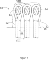
- the figures 7 and 8th show an arrangement 10 for introducing tensile or longitudinal forces according to a further particular embodiment of the invention, according to which the fastening bolts 18, at least at the point at which a respective tension bolt 20 acts, are configured in cross section in such a way that they have a higher moment of inertia in the load direction than vertically to the load direction.
- figure 8 shows a sectional view taken along the line VIII-VIII of FIG figure 7 .
- the fastening bolts 18 are configured here with a cross section in the form of a rectangle with rounded corners, the longer side of the rectangle running parallel to the direction of loading.
- the cross section of the eyelet 24 is also preferably adapted to the cross section of the fastening bolt 18 in this embodiment.
- the figures 9 and 10 show an arrangement 10 for the introduction of tensile or longitudinal forces according to a further particular embodiment of the invention, according to which the fastening bolts 18 each comprise at least one wedge-shaped element 32 for applying a prestressing force.
- the fastening bolts 18 can be designed in several parts, in particular in two or three parts.
- the figures 9 and 10 show a two-part embodiment of the fastening bolts 18, wherein figure 10 a sectional view along line XX of FIG figure 9 shows.
- the wedge-shaped element 32 has in this Embodiment a pointed end 34 and a blunt end 36 on. By moving the wedge-shaped element 32 in the direction of the pointed end 34, a preload force can be applied to the tie bolt 20.
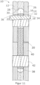
- figure 11 shows an arrangement 10 for introducing tensile or longitudinal forces according to a further particular embodiment of the invention, according to which a first end 22 of the tie bolt 20 extends into the component 12 and is connected to the component 12 and a second end 38 of the tie bolt 20 in a Connecting part 40 extends and is connected to the connecting part 40.
- figure 11 1 shows the connection of the tension bolt 20 to the component 12 according to an embodiment of the invention with a multi-part fastening bolt 20 having a wedge-shaped element 32 .
- this connection can also be provided by any other embodiment of the invention.
- figure 11 also shows the connection of the tension bolt 20 to the connection part 40 by means of a second fastening bolt 42, which can be designed according to the invention or according to a connection according to the prior art.
- the tie bolt 20 may have an eyelet 24 at only one of its first and second ends 22,38 and a threaded shank 17 (not shown) at the other of its first and second ends 22,38.
- the threaded shank 17 enables a screw connection into a threaded bore 15 (not shown) provided in the second fastening bolt 42 .
- the arrangement 10 shown for the introduction of tensile or longitudinal forces can be used in a further preferred embodiment of the invention to produce a blade connection for a rotor blade of a wind turbine.
- the blade connection serves to connect the rotor blade to a connection part 40, in particular a rotor hub.
- the component 12 is a rotor blade, in particular a rotor blade of a wind turbine.
- the connecting part 40 can be a rotor hub, for example.
- the arrangement 10 shown for the introduction of tensile or longitudinal forces can be used in a further preferred embodiment of the invention to produce a rotor blade for a wind turbine from a transversely divided hollow profile with a butt joint.
- the component 12 and the connection part 40 then correspond in this Embodiment each part of the transversely divided hollow profile.
- the or each tension bolt 20 preferably has an eyelet 24 at both of its first and second ends 22, 38, through which an associated fastening bolt 18 extends in each case.
- a plurality of tension bolts 20 can also act on a fastening bolt 18 .
- sectional view along the line XIII-XIII of figure 12 shows an embodiment with two tie bolts 20. Further embodiments can also have three or more tie bolts 20.
- figure 14 shows an arrangement 10 for the introduction of tensile or longitudinal forces according to a further special embodiment of the invention, according to which the transverse recesses 14 are arranged alternately in several planes offset to one another.
- the planes here are both perpendicular to the cutting plane and perpendicular to the longitudinal axes of the tie bolts 20.
- the in figure 14 The sectional view shown shows an embodiment in which the transverse recesses 14 are arranged alternately offset from one another in two planes.
- the transverse recesses 14 can also be arranged in three or more planes relative to one another.
- the transverse recesses 14 can also have a blockwise or irregular arrangement with respect to one another.
- the planes can be adapted to the shape of the component 12 and/or the connection part 40 .
- the in the figures 15 and 16 The further embodiment of the invention shown provides an arrangement for the introduction of tensile or longitudinal forces, in which a first end 22 of the tension bolt 20 is designed as a multi-armed end, each with an eyelet 24 .
- An associated fastening bolt 18 extends through each eyelet 24.
- the ends of the tension bolt(s) 20 can extend into a plurality of holes 16 according to this embodiment of the invention.
Landscapes
- Engineering & Computer Science (AREA)
- Life Sciences & Earth Sciences (AREA)
- Sustainable Development (AREA)
- Sustainable Energy (AREA)
- Chemical & Material Sciences (AREA)
- Combustion & Propulsion (AREA)
- Mechanical Engineering (AREA)
- General Engineering & Computer Science (AREA)
- Connection Of Plates (AREA)
Claims (9)
- Agencement (10) pour l'introduction d'une force de traction ou longitudinale dans un composant (12) pourvu d'évidements transversaux (14) pour des boulons de fixation (18), au moins un boulon de traction (20) prévu pour l'introduction d'une force, comprenant une première extrémité (22) et une deuxième extrémité, s'engageant sur chacun des boulons de fixation (18), le ou chaque boulon de traction (20) s'étendant dans un trou (16) dans le composant (12) et présentant à au moins une de ses première et deuxième extrémités (22) un œillet (24) à travers lequel s'étend un boulon de fixation (18) associé, le composant (12) étant un composant composite ou un composant en matière plastique composite fibreuse.
- Agencement (10) selon la revendication 1, dans lequel les boulons de fixation (18) sont sécurisés par un moyen de sécurisation contre un mouvement par rapport au composant (12).
- Agencement (10) selon la revendication 1 ou 2, dans lequel les évidements transversaux (14) sont agencés côte à côte dans un plan.
- Agencement (10) selon l'une quelconque des revendications précédentes, dans lequel un rapport a/d entre une distance a entre les axes longitudinaux de deux évidements transversaux adjacents (14) et un diamètre d des deux évidements transversaux adjacents (14) a une valeur dans la plage comprise entre environ 2 et environ 3.
- Agencement (10) selon l'une quelconque des revendications 1 à 4, dans lequel l'une des première et deuxième extrémités (22, 38) du boulon de traction (20) est réalisée sous la forme d'une extrémité à plusieurs bras avec respectivement un œillet (24) à travers lequel s'étend respectivement un boulon de fixation (18) associé.
- Agencement (10) selon l'une quelconque des revendications précédentes, dans lequel l'une des première et deuxième extrémités (22, 38) du boulon de traction (20) s'étend dans une pièce de raccordement (40) et est reliée à la pièce de raccordement (40).
- Raccordement de pale pour une pale de rotor d'une éolienne pour le raccordement de la pale de rotor à une pièce de raccordement (40), notamment un moyeu de rotor, comprenant un agencement (10) selon la revendication 6, dans lequel le composant (12) est une pale de rotor et le raccordement à la pièce de raccordement (40) est réalisé au moyen des boulons de traction (20).
- Pale de rotor pour une éolienne constituée d'un profilé creux divisé transversalement avec une liaison bout-à-bout, comprenant un agencement (10) selon la revendication 6.
- Procédé de fabrication d'un agencement (10) pour l'introduction d'une force de traction ou longitudinale selon l'une des revendications 1 à 6, comprenant les étapes suivantes :la fourniture d'un composant composite ou d'un composant en matière plastique composite fibreuse (12) avec des trous (16) et des évidements transversaux (14), l'agencement de boulons de traction (20), qui présentent chacun un œillet (24) à au moins une extrémité (22, 38), dans des trous associés (16),l'insertion de boulons de fixation (18) dans les évidements transversaux (14) et à travers les œillets (24), etla sécurisation des boulons de fixation (18).
Applications Claiming Priority (2)
| Application Number | Priority Date | Filing Date | Title |
|---|---|---|---|
| DE102018114098.3A DE102018114098A1 (de) | 2018-06-13 | 2018-06-13 | Anordnung zur Zug- bzw. Längskrafteinleitung sowie Verfahren zur Herstellung einer solchen Anordnung |
| PCT/DE2019/100503 WO2019238165A1 (fr) | 2018-06-13 | 2019-06-05 | Dispositif pour l'introduction de force longitudinale ou de traction ainsi que procédé pour la fabrication d'un tel dispositif |
Publications (3)
| Publication Number | Publication Date |
|---|---|
| EP3807523A1 EP3807523A1 (fr) | 2021-04-21 |
| EP3807523C0 EP3807523C0 (fr) | 2023-08-30 |
| EP3807523B1 true EP3807523B1 (fr) | 2023-08-30 |
Family
ID=67060240
Family Applications (1)
| Application Number | Title | Priority Date | Filing Date |
|---|---|---|---|
| EP19733392.5A Active EP3807523B1 (fr) | 2018-06-13 | 2019-06-05 | Dispositif pour l'introduction de force longitudinale ou de traction ainsi que procédé pour la fabrication d'un tel dispositif |
Country Status (3)
| Country | Link |
|---|---|
| EP (1) | EP3807523B1 (fr) |
| DE (1) | DE102018114098A1 (fr) |
| WO (1) | WO2019238165A1 (fr) |
Family Cites Families (5)
| Publication number | Priority date | Publication date | Assignee | Title |
|---|---|---|---|---|
| DE2832098C2 (de) | 1978-07-21 | 1982-06-03 | Messerschmitt-Bölkow-Blohm GmbH, 8000 München | Anordnung zur Zug- bzw. Längskrafteinleitung bei einem Bauteil in Sandwichbauweise |
| DE3608953A1 (de) * | 1986-03-18 | 1987-09-24 | Deha Baubedarf Kg | Fassadenplattenanker |
| US7517194B2 (en) * | 2006-04-30 | 2009-04-14 | General Electric Company | Rotor blade for a wind turbine |
| JP5242920B2 (ja) * | 2007-01-23 | 2013-07-24 | 株式会社日立製作所 | 風車用分割翼 |
| DE102010046518A1 (de) * | 2010-09-22 | 2012-03-22 | Nordex Energy Gmbh | Rotorblatt oder Rotorsegment für eine Windenergieanlage |
-
2018
- 2018-06-13 DE DE102018114098.3A patent/DE102018114098A1/de active Pending
-
2019
- 2019-06-05 EP EP19733392.5A patent/EP3807523B1/fr active Active
- 2019-06-05 WO PCT/DE2019/100503 patent/WO2019238165A1/fr unknown
Also Published As
| Publication number | Publication date |
|---|---|
| WO2019238165A1 (fr) | 2019-12-19 |
| EP3807523A1 (fr) | 2021-04-21 |
| DE102018114098A1 (de) | 2019-12-19 |
| EP3807523C0 (fr) | 2023-08-30 |
Similar Documents
| Publication | Publication Date | Title |
|---|---|---|
| DE102006022279B4 (de) | Rotorblatt für eine Windenergieanlage | |
| EP2786026B1 (fr) | Barre profilée, assemblage de profilés et procédé de fabrication d'un assemblage de profilés | |
| EP3469212B1 (fr) | Rotor pour éolienne, pale de rotor pour éolienne, manchon et procédé de montage d'un rotor | |
| DE102014208934B4 (de) | Lagerstruktur zur Lagerung von Windturbinenkomponenten | |
| DE69912867T2 (de) | Befestigungsvorrichtung für einen Triebwerkträger eines Flugzeuges | |
| DE2942519A1 (de) | Gabelkopf zur befestigung von rotorblaettern an einem hubschrauber-rotormast | |
| DE69800448T2 (de) | Verfahren zum Verbinden von Verbindungselementen und Bewehrungsstäben und dgl. Verbindungselement | |
| EP2434143B1 (fr) | Pale de rotor ou segment d'une pale de rotor pour une éolienne | |
| DE102011017460A1 (de) | Faserverbundbauteil, Flügelspitzenverlängerung und Flugzeug mit einem Faserverbundteil | |
| DE60204787T2 (de) | Konstruktionsteile für flugzeug | |
| EP3376024A1 (fr) | Pale de rotor d'éolienne divisible comprenant une liaison par boulonnage | |
| EP3807523B1 (fr) | Dispositif pour l'introduction de force longitudinale ou de traction ainsi que procédé pour la fabrication d'un tel dispositif | |
| EP3425195A1 (fr) | Pale de rotor d'éolienne divisible comprenant un module de douilles | |
| EP2133480B1 (fr) | Procédé destiné à la liaison de deux composants en bois | |
| WO1991000433A1 (fr) | Agencement d'ancrage de barres | |
| EP4146946A1 (fr) | Liaison de composants par complémentarité de forme, élément de liaison et accouplement de véhicule ferroviaire comportant une telle liaison de composants pour lier au moins deux composants | |
| DE102020205196B4 (de) | Crashelement, Fahrwerksteil und Fahrzeug | |
| DE2033979A1 (de) | Schäkel | |
| DE102014212828A1 (de) | Kraftübertragungselement für einen Prüfstand zum Testen eines Lagers sowie Prüfstand | |
| EP3372753B1 (fr) | Procédé, dispositif d'arrêt et système de précontrainte d'une tour | |
| EP3649371B1 (fr) | Système d'éléments statiquement résistants dans un seul bâtiment | |
| EP0930443A2 (fr) | Procédé de fabrication d'une bielle très chargée et bielle obtenue selon ce procédé | |
| DE9015572U1 (de) | Verbindungselement für Seile | |
| DE20306942U1 (de) | System miteinander verbundener Bauelemente | |
| DE10216918B4 (de) | Gabelkopf |
Legal Events
| Date | Code | Title | Description |
|---|---|---|---|
| STAA | Information on the status of an ep patent application or granted ep patent |
Free format text: STATUS: UNKNOWN |
|
| STAA | Information on the status of an ep patent application or granted ep patent |
Free format text: STATUS: THE INTERNATIONAL PUBLICATION HAS BEEN MADE |
|
| STAA | Information on the status of an ep patent application or granted ep patent |
Free format text: STATUS: THE INTERNATIONAL PUBLICATION HAS BEEN MADE |
|
| PUAI | Public reference made under article 153(3) epc to a published international application that has entered the european phase |
Free format text: ORIGINAL CODE: 0009012 |
|
| STAA | Information on the status of an ep patent application or granted ep patent |
Free format text: STATUS: REQUEST FOR EXAMINATION WAS MADE |
|
| 17P | Request for examination filed |
Effective date: 20201117 |
|
| AK | Designated contracting states |
Kind code of ref document: A1 Designated state(s): AL AT BE BG CH CY CZ DE DK EE ES FI FR GB GR HR HU IE IS IT LI LT LU LV MC MK MT NL NO PL PT RO RS SE SI SK SM TR |
|
| AX | Request for extension of the european patent |
Extension state: BA ME |
|
| DAV | Request for validation of the european patent (deleted) | ||
| DAX | Request for extension of the european patent (deleted) | ||
| GRAP | Despatch of communication of intention to grant a patent |
Free format text: ORIGINAL CODE: EPIDOSNIGR1 |
|
| STAA | Information on the status of an ep patent application or granted ep patent |
Free format text: STATUS: GRANT OF PATENT IS INTENDED |
|
| INTG | Intention to grant announced |
Effective date: 20230322 |
|
| GRAS | Grant fee paid |
Free format text: ORIGINAL CODE: EPIDOSNIGR3 |
|
| GRAA | (expected) grant |
Free format text: ORIGINAL CODE: 0009210 |
|
| STAA | Information on the status of an ep patent application or granted ep patent |
Free format text: STATUS: THE PATENT HAS BEEN GRANTED |
|
| AK | Designated contracting states |
Kind code of ref document: B1 Designated state(s): AL AT BE BG CH CY CZ DE DK EE ES FI FR GB GR HR HU IE IS IT LI LT LU LV MC MK MT NL NO PL PT RO RS SE SI SK SM TR |
|
| REG | Reference to a national code |
Ref country code: GB Ref legal event code: FG4D Free format text: NOT ENGLISH |
|
| REG | Reference to a national code |
Ref country code: CH Ref legal event code: EP |
|
| REG | Reference to a national code |
Ref country code: DE Ref legal event code: R096 Ref document number: 502019009157 Country of ref document: DE |
|
| REG | Reference to a national code |
Ref country code: IE Ref legal event code: FG4D Free format text: LANGUAGE OF EP DOCUMENT: GERMAN |
|
| U01 | Request for unitary effect filed |
Effective date: 20230921 |
|
| U07 | Unitary effect registered |
Designated state(s): AT BE BG DE DK EE FI FR IT LT LU LV MT NL PT SE SI Effective date: 20230929 |
|
| PG25 | Lapsed in a contracting state [announced via postgrant information from national office to epo] |
Ref country code: GR Free format text: LAPSE BECAUSE OF FAILURE TO SUBMIT A TRANSLATION OF THE DESCRIPTION OR TO PAY THE FEE WITHIN THE PRESCRIBED TIME-LIMIT Effective date: 20231201 |
|
| PG25 | Lapsed in a contracting state [announced via postgrant information from national office to epo] |
Ref country code: IS Free format text: LAPSE BECAUSE OF FAILURE TO SUBMIT A TRANSLATION OF THE DESCRIPTION OR TO PAY THE FEE WITHIN THE PRESCRIBED TIME-LIMIT Effective date: 20231230 |
|
| PG25 | Lapsed in a contracting state [announced via postgrant information from national office to epo] |
Ref country code: RS Free format text: LAPSE BECAUSE OF FAILURE TO SUBMIT A TRANSLATION OF THE DESCRIPTION OR TO PAY THE FEE WITHIN THE PRESCRIBED TIME-LIMIT Effective date: 20230830 Ref country code: NO Free format text: LAPSE BECAUSE OF FAILURE TO SUBMIT A TRANSLATION OF THE DESCRIPTION OR TO PAY THE FEE WITHIN THE PRESCRIBED TIME-LIMIT Effective date: 20231130 Ref country code: IS Free format text: LAPSE BECAUSE OF FAILURE TO SUBMIT A TRANSLATION OF THE DESCRIPTION OR TO PAY THE FEE WITHIN THE PRESCRIBED TIME-LIMIT Effective date: 20231230 Ref country code: HR Free format text: LAPSE BECAUSE OF FAILURE TO SUBMIT A TRANSLATION OF THE DESCRIPTION OR TO PAY THE FEE WITHIN THE PRESCRIBED TIME-LIMIT Effective date: 20230830 Ref country code: GR Free format text: LAPSE BECAUSE OF FAILURE TO SUBMIT A TRANSLATION OF THE DESCRIPTION OR TO PAY THE FEE WITHIN THE PRESCRIBED TIME-LIMIT Effective date: 20231201 |
|
| PG25 | Lapsed in a contracting state [announced via postgrant information from national office to epo] |
Ref country code: PL Free format text: LAPSE BECAUSE OF FAILURE TO SUBMIT A TRANSLATION OF THE DESCRIPTION OR TO PAY THE FEE WITHIN THE PRESCRIBED TIME-LIMIT Effective date: 20230830 |
|
| PG25 | Lapsed in a contracting state [announced via postgrant information from national office to epo] |
Ref country code: ES Free format text: LAPSE BECAUSE OF FAILURE TO SUBMIT A TRANSLATION OF THE DESCRIPTION OR TO PAY THE FEE WITHIN THE PRESCRIBED TIME-LIMIT Effective date: 20230830 |
|
| PG25 | Lapsed in a contracting state [announced via postgrant information from national office to epo] |
Ref country code: SM Free format text: LAPSE BECAUSE OF FAILURE TO SUBMIT A TRANSLATION OF THE DESCRIPTION OR TO PAY THE FEE WITHIN THE PRESCRIBED TIME-LIMIT Effective date: 20230830 Ref country code: RO Free format text: LAPSE BECAUSE OF FAILURE TO SUBMIT A TRANSLATION OF THE DESCRIPTION OR TO PAY THE FEE WITHIN THE PRESCRIBED TIME-LIMIT Effective date: 20230830 Ref country code: ES Free format text: LAPSE BECAUSE OF FAILURE TO SUBMIT A TRANSLATION OF THE DESCRIPTION OR TO PAY THE FEE WITHIN THE PRESCRIBED TIME-LIMIT Effective date: 20230830 Ref country code: CZ Free format text: LAPSE BECAUSE OF FAILURE TO SUBMIT A TRANSLATION OF THE DESCRIPTION OR TO PAY THE FEE WITHIN THE PRESCRIBED TIME-LIMIT Effective date: 20230830 Ref country code: SK Free format text: LAPSE BECAUSE OF FAILURE TO SUBMIT A TRANSLATION OF THE DESCRIPTION OR TO PAY THE FEE WITHIN THE PRESCRIBED TIME-LIMIT Effective date: 20230830 |
|
| REG | Reference to a national code |
Ref country code: DE Ref legal event code: R097 Ref document number: 502019009157 Country of ref document: DE |
|
| PLBE | No opposition filed within time limit |
Free format text: ORIGINAL CODE: 0009261 |
|
| STAA | Information on the status of an ep patent application or granted ep patent |
Free format text: STATUS: NO OPPOSITION FILED WITHIN TIME LIMIT |
|
| U20 | Renewal fee paid [unitary effect] |
Year of fee payment: 6 Effective date: 20240605 |
|
| 26N | No opposition filed |
Effective date: 20240603 |