EP3807017B1 - 1d-ultraschallwandler-einheit für die bereichsüberwachung - Google Patents
1d-ultraschallwandler-einheit für die bereichsüberwachung Download PDFInfo
- Publication number
- EP3807017B1 EP3807017B1 EP19731595.5A EP19731595A EP3807017B1 EP 3807017 B1 EP3807017 B1 EP 3807017B1 EP 19731595 A EP19731595 A EP 19731595A EP 3807017 B1 EP3807017 B1 EP 3807017B1
- Authority
- EP
- European Patent Office
- Prior art keywords
- sound
- ultrasonic transducer
- housing
- ultrasonic
- transducer unit
- Prior art date
- Legal status (The legal status is an assumption and is not a legal conclusion. Google has not performed a legal analysis and makes no representation as to the accuracy of the status listed.)
- Active
Links
Images
Classifications
-
- B—PERFORMING OPERATIONS; TRANSPORTING
- B06—GENERATING OR TRANSMITTING MECHANICAL VIBRATIONS IN GENERAL
- B06B—METHODS OR APPARATUS FOR GENERATING OR TRANSMITTING MECHANICAL VIBRATIONS OF INFRASONIC, SONIC, OR ULTRASONIC FREQUENCY, e.g. FOR PERFORMING MECHANICAL WORK IN GENERAL
- B06B1/00—Methods or apparatus for generating mechanical vibrations of infrasonic, sonic, or ultrasonic frequency
- B06B1/02—Methods or apparatus for generating mechanical vibrations of infrasonic, sonic, or ultrasonic frequency making use of electrical energy
- B06B1/06—Methods or apparatus for generating mechanical vibrations of infrasonic, sonic, or ultrasonic frequency making use of electrical energy operating with piezoelectric effect or with electrostriction
- B06B1/0607—Methods or apparatus for generating mechanical vibrations of infrasonic, sonic, or ultrasonic frequency making use of electrical energy operating with piezoelectric effect or with electrostriction using multiple elements
- B06B1/0622—Methods or apparatus for generating mechanical vibrations of infrasonic, sonic, or ultrasonic frequency making use of electrical energy operating with piezoelectric effect or with electrostriction using multiple elements on one surface
-
- G—PHYSICS
- G01—MEASURING; TESTING
- G01N—INVESTIGATING OR ANALYSING MATERIALS BY DETERMINING THEIR CHEMICAL OR PHYSICAL PROPERTIES
- G01N29/00—Investigating or analysing materials by the use of ultrasonic, sonic or infrasonic waves; Visualisation of the interior of objects by transmitting ultrasonic or sonic waves through the object
- G01N29/22—Details, e.g. general constructional or apparatus details
- G01N29/24—Probes
- G01N29/2462—Probes with waveguides, e.g. SAW devices
-
- G—PHYSICS
- G01—MEASURING; TESTING
- G01N—INVESTIGATING OR ANALYSING MATERIALS BY DETERMINING THEIR CHEMICAL OR PHYSICAL PROPERTIES
- G01N29/00—Investigating or analysing materials by the use of ultrasonic, sonic or infrasonic waves; Visualisation of the interior of objects by transmitting ultrasonic or sonic waves through the object
- G01N29/22—Details, e.g. general constructional or apparatus details
- G01N29/26—Arrangements for orientation or scanning by relative movement of the head and the sensor
- G01N29/262—Arrangements for orientation or scanning by relative movement of the head and the sensor by electronic orientation or focusing, e.g. with phased arrays
-
- G—PHYSICS
- G01—MEASURING; TESTING
- G01N—INVESTIGATING OR ANALYSING MATERIALS BY DETERMINING THEIR CHEMICAL OR PHYSICAL PROPERTIES
- G01N29/00—Investigating or analysing materials by the use of ultrasonic, sonic or infrasonic waves; Visualisation of the interior of objects by transmitting ultrasonic or sonic waves through the object
- G01N29/22—Details, e.g. general constructional or apparatus details
- G01N29/28—Details, e.g. general constructional or apparatus details providing acoustic coupling, e.g. water
-
- G—PHYSICS
- G01—MEASURING; TESTING
- G01N—INVESTIGATING OR ANALYSING MATERIALS BY DETERMINING THEIR CHEMICAL OR PHYSICAL PROPERTIES
- G01N29/00—Investigating or analysing materials by the use of ultrasonic, sonic or infrasonic waves; Visualisation of the interior of objects by transmitting ultrasonic or sonic waves through the object
- G01N29/34—Generating the ultrasonic, sonic or infrasonic waves, e.g. electronic circuits specially adapted therefor
- G01N29/348—Generating the ultrasonic, sonic or infrasonic waves, e.g. electronic circuits specially adapted therefor with frequency characteristics, e.g. single frequency signals, chirp signals
-
- G—PHYSICS
- G01—MEASURING; TESTING
- G01S—RADIO DIRECTION-FINDING; RADIO NAVIGATION; DETERMINING DISTANCE OR VELOCITY BY USE OF RADIO WAVES; LOCATING OR PRESENCE-DETECTING BY USE OF THE REFLECTION OR RERADIATION OF RADIO WAVES; ANALOGOUS ARRANGEMENTS USING OTHER WAVES
- G01S15/00—Systems using the reflection or reradiation of acoustic waves, e.g. sonar systems
- G01S15/02—Systems using the reflection or reradiation of acoustic waves, e.g. sonar systems using reflection of acoustic waves
-
- G—PHYSICS
- G01—MEASURING; TESTING
- G01S—RADIO DIRECTION-FINDING; RADIO NAVIGATION; DETERMINING DISTANCE OR VELOCITY BY USE OF RADIO WAVES; LOCATING OR PRESENCE-DETECTING BY USE OF THE REFLECTION OR RERADIATION OF RADIO WAVES; ANALOGOUS ARRANGEMENTS USING OTHER WAVES
- G01S15/00—Systems using the reflection or reradiation of acoustic waves, e.g. sonar systems
- G01S15/02—Systems using the reflection or reradiation of acoustic waves, e.g. sonar systems using reflection of acoustic waves
- G01S15/06—Systems determining the position data of a target
- G01S15/42—Simultaneous measurement of distance and other co-ordinates
-
- G—PHYSICS
- G01—MEASURING; TESTING
- G01S—RADIO DIRECTION-FINDING; RADIO NAVIGATION; DETERMINING DISTANCE OR VELOCITY BY USE OF RADIO WAVES; LOCATING OR PRESENCE-DETECTING BY USE OF THE REFLECTION OR RERADIATION OF RADIO WAVES; ANALOGOUS ARRANGEMENTS USING OTHER WAVES
- G01S15/00—Systems using the reflection or reradiation of acoustic waves, e.g. sonar systems
- G01S15/88—Sonar systems specially adapted for specific applications
-
- G—PHYSICS
- G01—MEASURING; TESTING
- G01S—RADIO DIRECTION-FINDING; RADIO NAVIGATION; DETERMINING DISTANCE OR VELOCITY BY USE OF RADIO WAVES; LOCATING OR PRESENCE-DETECTING BY USE OF THE REFLECTION OR RERADIATION OF RADIO WAVES; ANALOGOUS ARRANGEMENTS USING OTHER WAVES
- G01S5/00—Position-fixing by co-ordinating two or more direction or position line determinations; Position-fixing by co-ordinating two or more distance determinations
- G01S5/02—Position-fixing by co-ordinating two or more direction or position line determinations; Position-fixing by co-ordinating two or more distance determinations using radio waves
-
- G—PHYSICS
- G01—MEASURING; TESTING
- G01S—RADIO DIRECTION-FINDING; RADIO NAVIGATION; DETERMINING DISTANCE OR VELOCITY BY USE OF RADIO WAVES; LOCATING OR PRESENCE-DETECTING BY USE OF THE REFLECTION OR RERADIATION OF RADIO WAVES; ANALOGOUS ARRANGEMENTS USING OTHER WAVES
- G01S7/00—Details of systems according to groups G01S13/00, G01S15/00, G01S17/00
- G01S7/52—Details of systems according to groups G01S13/00, G01S15/00, G01S17/00 of systems according to group G01S15/00
- G01S7/521—Constructional features
-
- G—PHYSICS
- G01—MEASURING; TESTING
- G01S—RADIO DIRECTION-FINDING; RADIO NAVIGATION; DETERMINING DISTANCE OR VELOCITY BY USE OF RADIO WAVES; LOCATING OR PRESENCE-DETECTING BY USE OF THE REFLECTION OR RERADIATION OF RADIO WAVES; ANALOGOUS ARRANGEMENTS USING OTHER WAVES
- G01S7/00—Details of systems according to groups G01S13/00, G01S15/00, G01S17/00
- G01S7/52—Details of systems according to groups G01S13/00, G01S15/00, G01S17/00 of systems according to group G01S15/00
- G01S7/54—Details of systems according to groups G01S13/00, G01S15/00, G01S17/00 of systems according to group G01S15/00 with receivers spaced apart
-
- G—PHYSICS
- G10—MUSICAL INSTRUMENTS; ACOUSTICS
- G10K—SOUND-PRODUCING DEVICES; METHODS OR DEVICES FOR PROTECTING AGAINST, OR FOR DAMPING, NOISE OR OTHER ACOUSTIC WAVES IN GENERAL; ACOUSTICS NOT OTHERWISE PROVIDED FOR
- G10K11/00—Methods or devices for transmitting, conducting or directing sound in general; Methods or devices for protecting against, or for damping, noise or other acoustic waves in general
- G10K11/18—Methods or devices for transmitting, conducting or directing sound
- G10K11/22—Methods or devices for transmitting, conducting or directing sound for conducting sound through hollow pipes, e.g. speaking tubes
-
- G—PHYSICS
- G10—MUSICAL INSTRUMENTS; ACOUSTICS
- G10K—SOUND-PRODUCING DEVICES; METHODS OR DEVICES FOR PROTECTING AGAINST, OR FOR DAMPING, NOISE OR OTHER ACOUSTIC WAVES IN GENERAL; ACOUSTICS NOT OTHERWISE PROVIDED FOR
- G10K11/00—Methods or devices for transmitting, conducting or directing sound in general; Methods or devices for protecting against, or for damping, noise or other acoustic waves in general
- G10K11/18—Methods or devices for transmitting, conducting or directing sound
- G10K11/26—Sound-focusing or directing, e.g. scanning
- G10K11/34—Sound-focusing or directing, e.g. scanning using electrical steering of transducer arrays, e.g. beam steering
- G10K11/341—Circuits therefor
- G10K11/346—Circuits therefor using phase variation
-
- G—PHYSICS
- G01—MEASURING; TESTING
- G01N—INVESTIGATING OR ANALYSING MATERIALS BY DETERMINING THEIR CHEMICAL OR PHYSICAL PROPERTIES
- G01N2291/00—Indexing codes associated with group G01N29/00
- G01N2291/10—Number of transducers
- G01N2291/106—Number of transducers one or more transducer arrays
Definitions
- the invention relates to a 1D ultrasonic transducer unit for area monitoring with at least three discrete and individually controllable ultrasonic transducers for detecting objects, contours or distances.
- Ultrasound or ultrasonic transducers are used in a wide variety of measuring arrangements. Depending on the application, the ultrasound is decoupled in a liquid or gaseous medium.
- the array has a layered structure consisting of a layer of electret between two electrode structures, one electrode structure comprising a plurality of independently addressable electrode elements, as a result of which local thickness oscillations of the electret layer are generated.
- a 1.5D array of ultrasonic transducers with improved near-field resolution is from the US 2013/0283918 A1 famous.
- the US 2014/0283611 A1 and the US 6,310,831 B1 describe phased array ultrasonic transducers and adaptive or compensating control methods.
- More ultrasonic transducers are from the EP 0 940 801 A2 as well as from “ Phased array transducer for emitting 40 kHz air-coupled ultrasound without grating lobes", Eric Konetzke et al., IEEE International Ultrasonic Symposium, 2015, pp. 1-4 and from " Air-coupled 40-kHz ultrasonic 2D-phased array based on a 3D-printed waveguide structure", Jäger et al., IEEE International Ultrasonic Symposium, 2017, pp.
- the ultrasonic transducers used For use in an industrial environment, the ultrasonic transducers used must be able to guarantee temperature stability of the measurement from -40°C to sometimes over +100°C and electromagnetic compatibility with other technical devices. In addition, the ultrasonic transducers must be robust against harsh environmental influences, such as dust, moisture, aggressive chemicals, as well as against mechanical impacts or against mechanical scratching.
- piezoelectric ceramics such as lead zirconate titanate (PZT) are used, which have high coupling factors compared to other piezoelectric materials such as quartz, electrets or PVFD.
- the coupling factor represents a measure of the conversion efficiency between mechanically and electrically stored energy.
- PZT depending on the excitation direction, these are in the range from 0.3 to approx. 0.75, for example.
- resonant mechanical vibrations can be generated in the piezoelectric body with the help of alternating voltages, which are referred to as planar, thickness or shear vibrations depending on the geometric propagation.
- Typical dimensions of the piezoelectric body, which are necessary for a resonant oscillation at a given frequency, can be estimated for these oscillation forms from the material-specific frequency constant.
- these frequency constants are typically between 1300 kHz ⁇ mm and 2600 kHz ⁇ mm, depending on the type of vibration.
- a thin disc made of PZT suitable for sensor technology therefore has a diameter of approx. 4 mm to 100 mm for excitation frequencies of 20 kHz to 500 kHz in planar mode. Due to the capacitive properties of such a thin disk, low excitation voltages can be converted well with appropriate polarization.
- the thickness of the piezoelectric material increases, higher voltages, quickly also in the kV range, have to be applied for the same frequency range, which means higher safety costs.
- the thickness of the piezoelectric body also changes its rigidity, which has a direct impact on the reception of sound waves.
- ultrasonic transducers are used in a phase-controlled, at least one-dimensional array (phased array), it should also be noted that the distances between adjacent ultrasonic transducers must not be greater than the wavelength of the ultrasonic wave or preferably not greater than half the wavelength.
- This distance condition limits the size of the individual transducers or the frequency ranges that are possible with a specific design/size of the ultrasonic transducer.
- the object of the invention is to specify a device that develops the prior art.
- a 1D ultrasonic transducer unit for area monitoring, comprising a housing, at least three ultrasonic transducers and a control unit, the control unit being designed to control each ultrasonic transducer individually, the housing having fastening means for fastening to a surface, the control unit is at least partially arranged in the housing, the housing has a communication interface, each ultrasonic transducer has a transducer housing, a piezoelectric body arranged in the transducer housing and a sound decoupling layer arranged at an open end of the transducer housing for decoupling into a gaseous medium and on a fixed Position Located within the housing, each ultrasonic transducer is configured to radiate and/or receive a sound wave having a matching operating frequency and the operating frequency of the sound waves at a Be ranges from 20 kHz to 400 kHz.
- the 1D ultrasonic transducer unit has one sound channel per ultrasonic transducer, with each sound channel having an input opening and an output opening, exactly one of the input openings is assigned to each sound decoupling layer, the output openings are arranged along a straight line, the output openings are each arranged in a wall of the housing or the sound channels penetrate the wall of the housing.
- a distance from the center of one of the exit openings to the center of an immediately adjacent exit opening corresponds at most to the wavelength in the gaseous medium or at most to half the wavelength in the gaseous medium, with the distance between two immediately adjacent exit openings being smaller than the distance associated with the corresponding entrance openings is ultrasonic transducers, a quotient of a surface area of the outlet opening to a surface area of the inlet opening has a value between 0.30 and 1.2 and each sound channel has at least a length corresponding to the diameter of the inlet opening.
- the ultrasonic transducers of the 1D ultrasonic transducer unit are individual, discrete components, with each ultrasonic transducer being arranged in the housing and connected to the housing and thus having fixed distances from all other ultrasonic transducers.
- two ultrasonic transducers arranged next to one another, between which no further ultrasonic transducer is arranged, are directly adjacent to one another.
- the individual sound channels are tubular or rod-shaped, with the tube diameter decreasing and/or the shape of the cross-sectional area changing and/or the course of the channel being curved.
- the sound channels have no edge over their entire length from the sound decoupling layer to their exit opening.
- the sound channels lead the sound waves generated by the individual ultrasonic transducers out of the housing or reflected sound waves back to the ultrasonic transducers.
- a wave front is thus created at the outlet openings on the housing wall or outside the housing due to superimposition.
- Wavefronts with an adjustable main propagation direction can be generated with the several individually controllable ultrasonic transducers by control that is offset in time or phase. This makes it possible to cover a larger measuring range, at least in one dimension, with just one 1D ultrasonic transducer unit.
- the structure of the surface of an object and/or the shape of an object can also be recorded. For example, the type of an object can be determined.
- the individual sound sources are relocated to the respective ends or the exit openings of the sound channels when superimposed or for superimposing to form a common wave front.
- This makes it possible to set the distances between the individual sound sources independently of the size, e.g. the diameter, of the individual ultrasonic transducers or independently of the distances between the individual ultrasonic transducers. In particular, it is possible to reduce the distances between the sound sources compared to the distances between the individual transducers.
- the distance between two transducers is at least 14 mm.
- the distance between two transducers is at least 14 mm.
- only wave fronts with frequencies up to a maximum of 22 kHz ( ⁇ ⁇ 14mm) or a maximum of 11 kHz ( ⁇ /2 ⁇ 14mm) can be realized without a sound channel.
- the generation of wavefronts with higher frequencies, i.e. smaller wavelengths, is only possible with the same ultrasonic transducers with the aid of the sound channels according to the invention, since the distance between the individual "sound sources" in the superimposition is not determined by the size of the transducer housing, but is only determined by the size and the distance between the sound channel outlet openings.
- the sound channels also ensure precise, targeted detection.
- the radiating aperture of the piezoelectric transducer e.g. a circular aperture with a diameter predetermined by the piezoelectric body, is changed by means of the sound channels in such a way that they meet the conditions of a desired array arrangement in at least one dimension.
- This enables the use of robust, reliable and/or inexpensive discrete ultrasonic transducers in a phased array arrangement.
- the phased-array arrangement enables a large viewing angle with just a single 1D ultrasonic transducer unit and thus reliable monitoring of fill levels, for example. It is also possible to recognize surface structures and/or objects or object shapes.
- the housing has a movable covering device, the covering device being designed to close the exit openings of all the sound channels.
- the sound channels can be closed by means of the cover device as long as the 1D ultrasonic transducer unit is not being used, as a result of which the ingress of foreign bodies/contaminants can be prevented.
- the 1D ultrasonic transducer unit includes, for example, an adjusting means.
- the quotient between the surface area of the second cross-sectional area and the surface area of the first cross-sectional area has a value between 0.5 and 1.5 or between 0.9 and 1.1 on.
- the surface area of the entry surface can be increased, reduced or retained, while at the same time a reduction in at least the width of the exit opening compared to the entry opening is achieved.
- each sound channel has a length from the sound decoupling layer of each ultrasonic transducer to the exit opening of the associated sound channel, the length being an integer multiple of an eighth of the wavelength of the sound frequency or an integer multiple of half the wavelength of the sound frequency.
- the exit openings of all sound channels lie in a common flat plane or in a curved surface.
- a curved surface e.g., a concave surface, focused wavefronts can be generated.
- each sound channel consists of a metal or a plastic.
- each sound channel comprises a metal or a plastic.
- each ultrasonic converter has a sound decoupling layer between the sound decoupling layer and the converter housing.
- control unit is arranged entirely or partially in the housing.
- the housing of the 1D ultrasonic transducer unit is designed in accordance with at least IP 40 protection.
- the housing has at least one signal interface for transmitting a measurement signal and/or a control signal.
- the signal output is, for example, as a communication interface designed to communicate with an external control unit by means of a bus system or protocol.
- the signal interface can also provide wireless data transmission, for example using Bluetooth.
- each ultrasonic transducer protrudes into the assigned input opening with the sound decoupling layer first, with each sound channel accommodating at least part of the assigned ultrasonic transducer with a precise fit.
- an inner shape of the sound channels in the area of the inlet opening according to this embodiment corresponds as closely as possible to an outer shape of the respective ultrasonic transducer.
- the housing of each ultrasonic transducer has a diameter of at least 7 mm.
- the housing of each ultrasonic converter is designed, for example, as a cylindrical metal cup.
- a surface of the sound decoupling layer, an edge of the metal cup and, for example, a sound decoupling layer arranged in between of each individual ultrasonic transducer each span a flat plane.
- each ultrasonic transducer has electromagnetic shielding at a reference potential.
- the electromagnetic shielding can also be formed completely or at least partially by the housing, in particular a metal cup serving as the housing.
- the 1D ultrasonic transducer unit can also have a common shield for all ultrasonic transducers, e.g. a common housing.
- each sound channel has a wall thickness of at least 0.5 mm or at least 1 mm.
- two sound channels are at a distance of at least 0.5 mm or at least 1 mm from one another over the entire length of the two sound channels.
- the housing comprises a planar rear wall and a front wall running parallel to the rear wall.
- the ultrasonic transducers are preferably attached to the rear wall and the sound channels preferably end on or in the front wall.
- not only the outlet openings of the sound channels but also the ultrasonic transducers and the inlet openings of the sound channels are arranged along a straight line.
- the straight line spanned through the entrances of the sound channels is, for example, significantly longer than the straight line spanned through the exit openings.
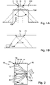
- FIG. 1A 12 shows a view of a first embodiment of a 1D ultrasonic transducer unit 10 for area monitoring according to the invention.
- the 1D ultrasonic transducer unit has a housing 14 which is attached to a wall 102 above a passage 104 using fastening means 11 .
- Sound waves 11 are generated by the 1D ultrasonic transducer unit 10 .
- the sound waves 11 have a main propagation direction, with the main propagation direction being pivotable in the image plane (dashed line, dotted line or dash-dotted line), as a result of which the entire area of the passage 104 can be reliably monitored.
- Objects 106 for example people and/or a floor and/or a side wall of the passage 104 reflect the sound waves 11.
- the entire area of the passage 104 can be reliably controlled by means of the 1D ultrasonic transducer unit 10.
- Objects 106 passing through passageway 104 may be identified by their shape.
- FIG. 1B a second embodiment according to the invention of the 1D ultrasonic transducer unit 10 is shown.
- the 1D ultrasonic transducer unit 10 is attached with the fastening means 11 to a building ceiling 106 above, so that objects 110 can be detected within the detection range of the unit 10, which is extended by the pivoting, by means of the ultrasonic waves.
- the shape or the surface structure of the objects 110 can also be determined using the unit 10 .
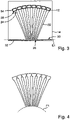
- FIG. 2 a sectional view of a housing 14 of an ultrasonic transducer unit 10 is shown.
- Five discrete ultrasonic transducers 12 are arranged in the housing 14 along a planar rear wall 16 of the housing 14 .
- Each ultrasonic transducer 12 has its own transducer housing 18 and a sound decoupling layer 20 .
- Each ultrasonic transducer 12 has a distance A1 from the center of the sound decoupling layer 20 to the center of the sound decoupling layer 20 to the one or more directly adjacent ultrasonic transducers 12 .
- a sound channel 22 is assigned to each ultrasonic transducer 12 , each sound channel 22 having an inlet opening 24 and an outlet opening 26 .
- the inlet openings 24 are each arranged in front of or around one of the ultrasonic transducers 12 in such a way that the respective ultrasonic transducer 12 radiates into the sound channel 22 .
- the outlet openings 26 of the sound channels 22 are arranged along a flat front wall 30 of the housing 14 opposite the rear wall or penetrate the front wall 30.
- Each two adjacent outlet openings 26 are at a distance A2 from the center of the outlet opening 26 to the center of the outlet opening 26 .
- the distance A2 of the outlet openings 26 is in each case less than or equal to the distance A1 of the assigned or associated ultrasonic transducers 12.
- a length L1 from each sound decoupling layer 20 to the exit opening 26 of the associated sound channel 22 is an integer multiple of an eighth of the wavelength of the sound frequency.
- a control unit is designed to control each ultrasonic transducer 12 individually.
- the 1D ultrasonic transducer unit 10 By driving the individual ultrasonic transducers 12 with a time offset or phase offset, the 1D ultrasonic transducer unit 10 generates planar ultrasonic waves with a main propagation direction (arrows), with the main propagation direction being adjustable by means of the phase offset between the sound waves emerging from the outlet openings 26 of the individual sound channels.
- each sound channel 22 run in such a way that the exit openings 26 of all sound channels 22 lie in a common planar plane E1.
- the front wall 30 of the housing 14 of the 1D ultrasonic transducer unit 10 runs within the plane E1.
- a region 34 of the respective sound channel 22 which is still in front of the inlet opening 24 of each sound channel 22 is designed in such a way that the respectively associated ultrasonic transducer 12 fits into the sound channel 22 with a precise fit.
- each sound channel 22 in the area has an inner diameter corresponding to the outer diameter D1 and an edge 36 serving as a stop.
- the housing 14 also includes a movable cover device 32.
- the covering device 32 is in a closed state.
- the covering device is arranged in front of the front wall 30 of the housing 14 with the outlet openings 26, so that the sound channels 22 are closed.
- the covering device 32 is no longer in front of the front housing wall 30 and the outlet openings 26, for example by folding or sliding, and the outlet openings 26 are exposed.
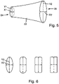
- FIG. 5 In the illustration of figure 5 is a single sound channel 22 is shown schematically, with the following the differences compared to the Figures 1 to 4 be explained.
- the inlet opening 24 has a cross-sectional area with a width x1 and a height y1
- the outlet opening 26 has a cross-sectional area with a width x2 and a height y2.
- the entrance opening 24 is formed in a circular shape, i.e., the width ⁇ 1 and the height y1 of the cross-sectional area have the same value.
- the exit opening 26 has an oval shape, so that the width x2 of the cross-sectional area is smaller than the width y2.
- the width x2 of the outlet opening 26 is preferably smaller than the width x1 of the inlet opening 26.
- the height y2 of the outlet opening 26, on the other hand, is preferably greater than the height y1 of the inlet opening 24.
- the increase in height of the sound channel 22 particularly preferably equals the decrease in the width of the sound channel 22 such that the area of the cross-sectional area of the inlet opening 24 corresponds to the area of the cross-sectional area of the outlet opening 26 .
- each exit opening 26 must be smaller than the wavelength of the sound frequency in order to be able to realize a distance from the center of the exit openings 26 to the center of an immediately adjacent exit opening 26 of at most the wavelength of the sound frequency.
Landscapes
- Engineering & Computer Science (AREA)
- Physics & Mathematics (AREA)
- Radar, Positioning & Navigation (AREA)
- Remote Sensing (AREA)
- General Physics & Mathematics (AREA)
- Acoustics & Sound (AREA)
- Computer Networks & Wireless Communication (AREA)
- Life Sciences & Earth Sciences (AREA)
- Health & Medical Sciences (AREA)
- Chemical & Material Sciences (AREA)
- Analytical Chemistry (AREA)
- Biochemistry (AREA)
- General Health & Medical Sciences (AREA)
- Immunology (AREA)
- Pathology (AREA)
- Multimedia (AREA)
- Mechanical Engineering (AREA)
- Transducers For Ultrasonic Waves (AREA)
Description
- Die Erfindung betrifft eine1D-Ultraschallwandler-Einheit für die Bereichsüberwachung mit mindestens drei diskreten und einzeln ansteuerbaren Ultraschallwandlern zur Erfassung von Objekten, Konturen oder Abständen. Ultraschall bzw. Ultraschallwandler werden in den unterschiedlichsten Messanordnungen verwendet. Je nach Anwendung wird der Ultraschall in ein flüssiges oder gasförmiges Medium ausgekoppelt.
- Aus der
WO 2008/135 004 A1 ist ein Ultraschallwandler-Array für die Anwendung in gasförmigen Medien bekannt. Das Array weist einen Schichtaufbau aus einer Schicht aus einem Elektret zwischen zwei Elektrodenstrukturen auf, wobei die eine Elektrodenstruktur mehrere unabhängig adressierbare Elektrodenelemente umfasst, wodurch lokale Dickenschwingungen der Elektretschicht erzeugt werden. - Ein 1,5D Array von Ultraschallwandlern mit verbesserter Nahfeldauflösung ist aus der
US 2013/0283918 A1 bekannt. In derUS 2014/0283611 A1 und derUS 6,310,831 B1 sind phasengesteuerte Ultraschallwandler-Arrays und adaptive bzw. kompensierende Steuerungsverfahren beschrieben. - Weitere Ultraschallwandler sind aus der
EP 0 940 801 A2 sowie aus "Phased array transducer for emitting 40 kHz air-coupled ultrasound without grating lobes", Eric Konetzke et al., IEEE International Ultrasonic Symposium, 2015, S. 1-4 und aus "Air-coupled 40-kHz ultrasonic 2D-phased array based on a 3D-printed waveguide structure", Jäger et al., IEEE International Ultrasonic Symposium, 2017, S. 1-4, und aus "Takahashi et al., Ultrasonic phased array sensor for electrical travel aids for visually impaired people, Proceedings of the spie -The international society for optical engineering spie - vertical-cavity surface-emitting lasers XIII, Bd. 6794, 3. Dezember 2007, Seite 67943V, ISSN: 0277-786X" und aus " "Manufactoring Murata: Ultrasonic Sensor Application Manual Cat. No. S15E-5, 1. Januar 2009, URL:https://cdn-reichelt.de/ documents/ datenblatt/8400/ultraschall%20sensor.pdf, Seite 3" bekannt. - Für den Einsatz in einer industriellen Umgebung müssen die eingesetzten Ultraschallwandler eine Temperaturstabilität der Messung von -40°C bis teilweise über +100°C und eine elektromagnetische Verträglichkeit mit anderen technischen Geräten gewährleisten können. Außerdem müssen die Ultraschallwandler gegenüber harschen Umwelteinflüssen, wie z.B. Staub, Nässe, aggressiven Chemikalien, sowie gegenüber mechanischen Schlägen oder gegenüber mechanischem Kratzen robust sein.
- Um hohe Detektionsreichweiten zu erzielen, werden piezoelektrische Keramiken, wie z.B. Blei-Zirkonat-Titanat (PZT) eingesetzt, die im Vergleich zu anderen piezoelektrischen Materialien, wie Quarz, Elektrete oder PVFD, hohe Kopplungsfaktoren besitzen. Der Kopplungsfaktor stellt dabei ein Maß für die Umwandlungseffizienz zwischen mechanisch und elektrischer gespeicherter Energie dar. Diese liegen für PZT je nach Anregungsrichtung beispielhaft im Bereich von 0,3 bis ca. 0,75.
- Je nach Polarisationsrichtung des piezoelektrischen Materials können mit Hilfe von Wechselspannungen resonante mechanische Schwingungen im piezoelektrischen Körper erzeugt werden, die je nach geometrischer Ausbreitung als Planar-, Dicken- oder Scheerschwingung bezeichnet werden. Für diese Schwingungsformen lassen sich aus der materialspezifischen Frequenzkonstanten typische Abmessungen des piezoelektrischen Körpers abschätzen, die für eine resonante Schwingung bei einer vorgegebenen Frequenz notwendig sind. Diese Frequenzkonstanten liegen für PZT je nach Schwingungsart typischerweise zwischen 1300 kHz∗mm bis 2600 kHz∗mm.
- Eine dünne Scheibe aus für Sensorik geeignetem PZT besitzt demnach für Anregungsfrequenzen von 20 kHz bis 500 kHz im Planarmodus einen Durchmesser von ca. 4 mm bis 100 mm. Aufgrund der kapazitativen Eigenschaften einer solchen dünnen Scheibe lassen sich bei entsprechender Polarisation niedrige Anregungsspannungen gut umsetzen.
- Größere Dicken der piezoscheibe sind nicht erstrebenswert. Einerseits müssen mit zunehmender Dicke des piezoelektrischen Materials für denselben Frequenzbereich höhere Spannungen, schnell auch im kV-Bereich, aufgebracht werden, was einen höheren Sicherheitsaufwand bedeutet. Andererseits verändert sich mit der Dicke des piezoelektrischen Körpers auch dessen Steifigkeit, was direkte Auswirkungen auf den Empfangsfall von Schallwellen hat.
- Bei einer Anwendung von mehreren Ultraschallwandlern in eine phasengesteuerten mindestens eindimensionalen Array (phased array) ist weiterhin zu beachten, dass die Abstände zwischen benachbarten Ultraschallwandlern nicht größer als die Wellenlänge der Ultraschallwelle oder bevorzugt nicht größer als die halbe Wellenlänge sein dürfen.
- Durch diese Abstandsbedingung wird entsprechend die Baugröße der einzelnen Wandler bzw. die mit einer bestimmten Bauform/Größe der Ultraschallwandler möglichen Frequenzbereiche beschränkt.
- Für einen Frequenzbereich zwischen 20 kHz und 500 kHz und eine Auskopplung In Luft ergib sich beispielsweise ein maximaler Abstände zwischen benachbarten Wandlern in der Größenordnung von ca. 8,5 mm bis ca. 0,3 mm. Der vorher beschriebene Wandler mit einer dünnen Scheibe aus für Sensorik geeignetem PZT weist jedoch schon aufgrund des Piezoscheibendurchmessers eine im Schnitt um mehr als 10 Mal größeren Durchmesser auf.
- Vor diesem Hintergrund besteht die Aufgabe der Erfindung darin, eine Vorrichtung anzugeben, die den Stand der Technik weiterbildet.
- Die Aufgabe wird durch eine 1D-Ultraschallwandler-Einheit für die Bereichsüberwachung mit den Merkmalen des Patentanspruchs 1 gelöst. Vorteilhafte Ausgestaltungen der Erfindung sind Gegenstand von Unteransprüchen.
- Gemäß dem Gegenstand der Erfindung wird eine 1D-Ultraschallwandler-Einheit für die Bereichsüberwachung bereitgestellt, umfassend ein Gehäuse, mindestens drei Ultraschallwandler und eine Steuereinheit, wobei die Steuereinheit dazu ausgelegt ist, jeden Ultraschallwandler einzeln anzusteuern, das Gehäuse Befestigungsmittel zur Befestigung an einer Oberfläche aufweist, die Steuereinheit zumindest teilweise in dem Gehäuse angeordnet ist, das Gehäuse eine Kommunikationsschnittstelle aufweist, jeder Ultraschallwandler jeweils ein Wandlergehäuse, einen in dem Wandlergehäuse angeordneten piezoelektrischen Körper und eine an einem offenen Ende des Wandlergehäuses angeordnete Schallauskoppelschicht zum Auskoppeln in ein gasförmiges Medium aufweist und an einer festen Position In dem Gehäuse angeordnet ist, jeder Ultraschallwandler dazu ausgelegt ist, eine Schallwelle mit einer übereinstimmenden Arbeitsfrequenz abzustrahlen und/oder zu empfangen und die Arbeitsfrequenz der Schallwellen in einem Bereich von 20 kHz bis 400 kHz liegt.
- Jeweils zwei zueinander unmittelbar benachbarte Ultraschallwandler weisen in dem Gehäuse einen Abstand von Mitte der Schallauskoppelschicht zu Mitte der Schallauskoppelschicht von höchstens 10 cm oder höchstens 5 cm oder höchstens 2 cm auf. Die 1D-Ultraschallwandler-Einheit weist pro Ultraschallwandler einen Schallkanal auf, wobei jeder Schallkanal eine Eingangsöffnung und eine Ausgangsöffnung aufweist, jeder Schallauskoppelschicht genau eine der Eingangsöffnungen zugeordnet ist, die Ausgangsöffnungen entlang einer Geraden angeordnet sind, die Ausgangsöffnungen jeweils in einer Wand des Gehäuses angeordnet sind oder die Schallkanäle die Wand des Gehäuses durchdringen. Ein Abstand von der Mitte einer der Ausgangsöffnung zu der Mitte einer unmittelbar benachbarten Ausgangsöffnung entspricht höchstens der Wellenlänge im gasförmigen Medium oder höchstens der Hälfte der Wellenlänge im gasförmigen Medium, wobei der Abstand zwischen zwei unmittelbar benachbarten Ausgangsöffnungen jeweils kleiner als der Abstand der den entsprechenden Eingangsöffnungen zugeordneten Ultraschallwandlern ist, ein Quotient aus einem Flächeninhalt der Ausgangsöffnung zu einem Flächeninhalt der Eingangsöffnung einen Wert zwischen 0,30 und 1,2 aufweist und jeder Schallkanal mindestens eine dem Durchmessers der Eingangsöffnung entsprechende Länge besitzt.
- Es versteht sich, dass es sich bei den Ultraschallwandlern der 1D-Ultraschallwandler-Einheit um einzelnen diskrete Bauteile handelt, wobei jeder Ultraschallwandler In dem Gehäuse angeordnet und mit dem Gehäuse verbunden ist und damit feste Abstände zu allen weiteren Ultraschallwandlern aufweist. Dabei sind zwei nebeneinander angeordnete Ultraschallwandler, zwischen denen kein weiterer Ultraschallwandler angeordnet ist, zueinander unmittelbar benachbarte.
- Es versteht sich auch, dass die einzelnen Schallkanäle rohrartig oder stangenförmig ausgebildet sind, wobei sich beispielsweise der Rohrdurchmesser verringert und/oder die Form der Querschnittsfläche verändert und/oder der Verlauf des Kanals bogenförmig ausgebildet ist. Vorteilhafterweise weisen die Schallkanäle über ihre gesamte Länge von der Schallauskopplungsschicht bis zu ihrer Ausgangsöffnung keine Kante auf.
- Die Schallkanäle führen die von den einzelnen Ultraschallwandlern erzeugten Schallwellen aus dem Gehäuse heraus bzw. reflektierte Schallwellen zu den Ultraschallwandlern zurück. So entsteht an den Ausgangsöffnungen an der Gehäusewand oder außerhalb des Gehäuses durch Überlagerung eine Wellenfront.
- Mit den mehreren einzeln ansteuerbaren Ultraschallwandlern lassen sich durch zeitlich versetzte bzw. Phasen-versetzte Ansteuerung Wellenfronten mit einstellbarer Hauptausbreitungsrichtung erzeugen. Hierdurch ist es möglich zumindest in einer Dimension einen größeren Messbereich mit nur einer 1D-Ultraschallwandler-Einheit zu erfassen. Außerdem kann zusätzlich die Struktur der Oberfläche eines Objekts und/oder die Form eines Objekts erfasst werden. So kann beispielsweise die Art eines Objekts bestimmt werden.
- Durch Anordnen von Schallkanälen vor den einzelnen Ultraschallwandlern werden die einzelnen Schallquellen bei Überlagerung bzw. für das Überlagern zu einer gemeinsamen Wellenfront an die jeweiligen Enden bzw. die Ausgangsöffnungen der Schallkanäle verlegt. Dies ermöglicht es, die Abstände zwischen den einzelnen Schallquellen unabhängig von der Größe, z.B. dem Durchmesser, der einzelnen Ultraschallwandler bzw. unabhängig von den Abständen zwischen den einzelnen Ultraschallwandlern einzustellen. Insbesondere ist es möglich, die Abstände zwischen den Schallquellen im Vergleich zu den Abständen zwischen den einzelnen Wandlern zu verringern.
- Bei einem Gehäusedurchmesser der einzelnen Ultraschallwandler von beispielsweise 7 mm beträgt der Abstand zweier Wandler mindestens 14 mm. Entsprechend sind ohne Schallkanal nur Wellenfronten mit Frequenzen bis höchstens 22 kHz (λ ≥ 14mm) bzw. bis höchstens 11 kHz (λ/2 ≥ 14mm) realisierbar. Das Erzeugen von Wellenfronten mit höheren Frequenzen, also kleineren Wellenlängen, ist mit denselben Ultraschallwandlern erst mit Hilfe der erfindungsgemäßen Schallkanäle möglich, da der Abstand der einzelnen "Schallquellen" bei der Überlagerung nicht durch die Größe der Wandlergehäuse, sondern nur noch durch die Größe und den Abstand der Schallkanalausgangsöffnungen bestimmt wird.
- Durch die Schallkanäle wird außerdem eine präzise, gerichtete Detektion sichergestellt.
- Die abstrahlende Apertur der piezoelektrischen Wandlers, z.B. eine kreisförmige Apertur mit einem durch den piezoelektrischen Körper vorgegebenen Durchmesser, wird mittels der Schallkanäle so verändert, dass sie in mindestens einer Dimension den Bedingungen einer gewünschten Array-Anordnung genügen. Dies ermöglicht den Einsatz robuster, zuverlässiger und/oder kostengünstiger diskreter Ultraschallwandler in einer phased-array Anordnung. Die phased-array Anordnung ermöglicht einen großen Blickwinkel mit nur einer einzigen 1D-Ultraschallwandler-Einheit und damit eine zuverlässige Überwachung beispielsweise von Füllständen. Auch das Erkennen von Oberflächenstrukturen und/oder Objekten bzw. Objektformen ist möglich.
- Es ist nicht nötig besonders kleine, beispielsweise integrierte Ultraschallwandler wie MEMS einzusetzen. Ebenso wenig ist es nötig mehrere Wandler-Einheiten anzubringen, auszulesen und gegebenenfalls aufeinander abzustimmen.
- Gemäß der Erfindung weist das Gehäuse eine bewegliche Abdeckvorrichtung auf, wobei die Abdeckvorrichtung dazu ausgelegt ist, die Ausgangsöffnungen aller Schallkanäle zu verschließen. Mittels der Abdeckvorrichtung können die Schallkanäle verschlossen werden, solange die 1D-Ultraschallwandler-Einheit nicht gebraucht wird, wodurch das Eindringen von Fremdkörpern/Verunreinigungen verhindert werden kann. Zum Öffnen und Schließen der Schallkanäle bzw. zum Bewegen der Abdeckvorrichtung umfasst die 1D-Ultraschallwandler-Einheit beispielsweise ein Stellmittel.
- Gemäß einer Weiterbildung weist der Quotient zwischen dem Flächeninhalt der zweiten Querschnittsfläche und dem Flächeninhalt der ersten Querschnittsfläche einen Wert zwischen 0,5 und 1,5 oder zwischen 0,9 und 1,1 auf. Der Flächeninhalt der Eingangsfläche kann erfindungsgemäß vergrößert, verkleinert oder erhalten bleiben, wobei gleichzeitig eine Verringerung zumindest der Breite der Ausgangsöffnung im Vergleich zu der Eingangsöffnung erreicht wird.
- Gemäß einer weiteren Ausführungsform besitzt jeder Schallkanal eine Länge von der Schallauskoppelschicht jedes Ultraschallwandlers zu der Ausgangsöffnung des zugeordneten Schallkanals, wobei die Länge ein ganzzahliges Vielfaches eines Achtels der Wellenlänge der Schallfrequenz oder ein ganzzahliges Vielfachen der halben Wellenlänge der Schallfrequenz beträgt.
- Gemäß der Erfindung liegen die Ausgangsöffnungen aller Schallkanäle in einer gemeinsamen planen Ebene oder in einer gekrümmten Fläche. Durch Anordnen in einer gekrümmten Fläche, z.B. einer konkaven Fläche, lassen sich beispielsweise fokussierte Wellenfronten erzeugen.
- In einer anderen Ausführungsform besteht jeder Schallkanal aus einem Metall oder einem Kunststoff. Alternativ umfasst jeder Schallkanal ein Metall oder einen Kunststoff.
- Gemäß einer weiteren Ausführungsform weist jeder Ultraschallwandler zwischen der Schallauskoppelschicht und dem Wandlergehäuse eine Schallentkopplungsschicht auf.
- In einer anderen Ausführungsform ist die Steuereinheit vollständig oder teilweise in dem Gehäuse angeordnet.
- Gemäß einer anderen Ausführungsform ist das Gehäuse der 1D-Ultraschallwandler-Einheit mindestens der IP 40 Schutzart entsprechend ausgebildet.
- In einer weiteren Weiterbildung weist das Gehäuse mindestens eine Signalschnittstelle zur Übermittlung eines Messsignals und/oder eines Steuersignals auf. Der Signalausgang ist beispielsweise als Kommunikationsschnittstelle ausgebildet, um mit einer externen Steuereinheit mittels eines Bus-Systems bzw. Protokolls zu kommunizieren. Ebenso kann die Signalschnittstelle eine drahtlose Datenübertragung beispielsweise mittels Bluetooth bereitstellen.
- Gemäß einer anderen Ausführungsform ragt jeder Ultraschallwandler mit der Schallauskoppelschicht voran in die zugeordnete Eingangsöffnung hinein, wobei in einer Weiterbildung jeder Schallkanal zumindest einen Teil des zugeordneten Ultraschallwandlers passgenau aufnimmt. Anders ausgedrückt entspricht eine innere Form der Schallkanäle im Bereich der Eingangsöffnung gemäß dieser Ausführungsform möglichst genau einer äußeren Form des jeweiligen Ultraschallwandlers.
- In einer weiteren Ausführungsform weist das Gehäuse jedes Ultraschallwandlers einen Durchmesser von mindestens 7 mm auf. Das Gehäuse jedes Ultraschallwandlers ist beispielsweise als ein zylinderförmiger Metallbecher ausgebildet. Gemäß einer Weiterbildung dieser Ausführungsform spannt eine Oberfläche der Schallauskoppelschicht, ein Rand des Metallbechers und beispielsweise eine dazwischen angeordnete Schallentkopplungsschicht jedes einzelnen Ultraschallwandlers jeweils eine plane Ebene auf.
- In einer anderen Ausführungsform weist jeder Ultraschallwandler eine auf einem Referenzpotential liegende elektromagnetische Abschirmung auf. Es versteht sich, dass die elektromagnetische Abschirmung auch vollständig oder zumindest teilweise durch das Gehäuse, insbesondere einen als Gehäuse dienenden Metallbecher ausgebildet sein kann. Alternativ kann die 1D-Ultraschallwandler-Einheit auch eine gemeinsame Abschirmung für alle Ultraschallwandler aufweisen, z.B. ein gemeinsames Gehäuse.
- In einer weiteren Ausführungsform weist jeder Schallkanal eine Wandstärke von mindestens 0,5 mm oder mindestens 1 mm auf. Gemäß einer anderen Weiterbildung weisen jeweils zwei Schallkanäle zueinander über eine gesamte Länge der beiden Schallkanäle einen Abstand von mindestens 0,5 mm oder mindestens 1 mm auf.
- Gemäß einer anderen Ausführungsform umfasst das Gehäuse eine plane Rückwand und eine parallel zu der Rückwand verlaufende vordere Wand. Hierdurch ist das Anbringen und Ausrichten der 1D-Ultrschallwandler-Einheit an Oberfläche besonders einfach und zuverlässig möglich. Die Ultraschallwandler sind bevorzugt an der Rückwand angebracht und die Schallkanäle enden bevorzugt an bzw. in der vorderen Wand. Besonders bevorzugt sind nicht nur die Ausgangsöffnungen der Schallkanäle, sondern auch die Ultraschallwandler sowie die Eingangsöffnungen der Schallkanäle entlang einer geraden angeordnet. Die durch die Eingänge der Schallkanäle aufgespannte Gerade ist beispielsweise deutlich länger als die durch die Ausgangsöffnungen aufgespannte Gerade.
- Die Erfindung wird nachfolgend unter Bezugnahme auf die Zeichnungen näher erläutert. Hierbei werden gleichartige Teile mit identischen Bezugszeichen beschriftet. Die dargestellten Ausführungsformen sind stark schematisiert, d.h. die Abstände und die lateralen und die vertikalen Erstreckung sind nicht maßstäblich und weisen, sofern nicht anders angegeben, auch keine ableitbaren geometrischen Relationen zueinander auf. Darin zeigt:
- Figur 1A
- eine Ansicht einer ersten erfindungsgemäßen Ausführungsform einer 1D-Ultraschallwandler-Einheit zur Bereichsüberwachung,
- Figur 1B
- eine Ansicht einer zweiten erfindungsgemäßen Ausführungsform einer 1D-Ultraschallwandler-Einheit zur Bereichsüberwachung,
- Figur 2
- eine Schnittansicht eines Beispiels eines Gehäuses einer 1D-Utraschallwandler-Einheit,
Figur 3 eine Ansicht eines weiteren Beispiels der Schallkanäle, - Figur 4
- eine Ansicht einer erfindungsgemäßen Ausführungsform der Schallkanäle,
- Figur 5
- eine Ansicht einer weiteren Ausführungsform eines einzelnen Schallkanals,
- Figur 6
- eine schematische Ansicht verschiedener Ausführungsformen einer Ausgangsfläche eines Schallkanals.
- Die Abbildung der
Figur 1A zeigt eine Ansicht einer ersten Ausführungsform einer erfindungsgemäßen 1D-Ultraschallwandler-Einheit 10 zur Bereichsüberwachung. Die 1D-Ultraschallwandler-Einheit weist ein Gehäuse 14 auf, welches mit Befestigungsmitteln 11 an einer Wand 102 oberhalb eines Durchgangs 104 angebracht ist. Durch die 1D-Ultraschallwandler-Einheit 10 werden Schallwellen 11 erzeugt. Die Schallwellen 11 weisen eine Hauptausbreitungsrichtung auf, wobei die Hauptausbreitungsrichtung in der Bildebene schwenkbar ist (gestrichelte Linie, gepunktete Linie oder strichpunktierte Linie), wodurch der gesamte Bereich des Durchgangs 104 zuverlässig überwacht werden kann. Objekte 106, z.B. Personen und/oder ein Boden und/oder eine Seitenwand des Durchgangs 104 reflektieren die Schallwellen 11. Mittels der 1D-Ultraschallwandler-Einheit 10 kann der komplette Bereich des Durchgangs 104 zuverlässig kontrolliert. Den Durchgang 104 durchquerende Objekte 106 können gegebenenfalls an ihrer Form erkannt werden. - In der Abbildung der
Figur 1B ist eine zweite erfindungsgemäße Ausführungsform der 1D-Ultraschallwandler-Einheit 10 dargestellt. Die 1D-Ulterschallwandlereinheit 10 ist mit den Befestigungsmitteln 11 an einer Gebäudedecke 106 oberhalb angebracht, so dass mittels der Ultraschallwellen Objekte 110 innerhalb des durch das Schwenken erweiterten Erfassungsbereichs der Einheit 10 erfasst werden können. Auch die Form oder die Oberflächenstruktur der Objekten 110 ist mittels der Einheit 10 ermittelbar. - In der Abbildung der
Figur 2 ist eine Schnittansicht eines Gehäuses 14 einer Ultraschallwandler-Einheit 10 dargestellt. In dem Gehäuse 14 sind entlang einer planen Rückwand 16 des Gehäuses 14 fünf diskrete Ultraschallwandler 12 angeordnet. Jeder Ultraschallwandler 12 weist ein eigenes Wandlergehäuse 18 und eine Schallauskoppelschicht 20 auf. Jeder Ultraschallwandler 12 weist zu dem oder den unmittelbar benachbarten Ultraschallwandlern 12 einen Abstand A1 von Mitte der Schallauskoppelschicht 20 zu Mitte der Schallauskoppelschicht 20 auf. - Jedem Ultraschallwandler 12 ist ein Schallkanal 22 zugeordnet, wobei jeder Schallkanal 22 eine Eingangsöffnung 24 und einen Ausgangsöffnung 26 aufweist. Die Eingangsöffnungen 24 sind jeweils so vor oder um einen der Ultraschallwandler 12 angeordnet, dass der jeweilige Ultraschallwandler 12 in den Schallkanal 22 hinein abstrahlt. Die Ausgangsöffnungen 26 der Schallkanäle 22 sind entlang einer der Rückwand gegenüberliegenden planen vorderen Wand 30 des Gehäuses 14 angeordnet bzw. durchdringen die vordere Wand 30.
- Jeweils zwei benachbarte Ausgangsöffnungen 26 weisen einen Abstand A2 von Mitte der Ausgangsöffnung 26 zu Mitte der Ausgangsöffnung 26 auf. Erfindungsgemäß ist der Abstand A2 der Ausgangsöffnungen 26 jeweils kleiner oder gleich dem Abstand A1 der zugeordneten bzw. zugehörigen Ultraschallwandler 12.
- Eine Länge L1 von jeder Schallauskoppelschicht 20 bis zu der Ausgangsöffnung 26 des zugehörigen Schallkanals 22 beträgt ein ganzzahliges Vielfachen eines Achtels der Wellenlänge der Schallfrequenz.
- Eine nicht dargestellte Steuereinheit ist dazu ausgelegt, jeden Ultraschallwandler 12 einzeln anzusteuern. Durch zeitlich versetztes bzw. Phasenversetztes Ansteuern der einzelnen Ultraschallwandler 12 erzeugt die 1D-Ultraschallwandler-Einheit 10 ebene Ultraschallwellen mit einer Hauptausbreitungsrichtung (Pfeile), wobei die Hauptausbreitungsrichtung mittels des Phasenversatzes zwischen den aus den Ausgangsöffnungen 26 der einzelnen Schallkanäle austretenden Schallwellen einstellbar ist.
- In dem in der
Figur 3 dargestellten Beispiel verlaufen die Schallkanäle 22 so, dass die Ausgangsöffnungen 26 aller Schallkanäle 22 in einer gemeinsamen planen Ebene E1 liegen. Im dargestellten Beispiel verläuft die vordere Wand 30 des Gehäuses 14 der 1D-Ultraschallwandler-Einheit 10 innerhalb der Ebene E1. Ein sich noch vor der Eingangsöffnung 24 jedes Schallkanals 22 befindlicher Bereich 34 des jeweiligen Schallkanals 22 ist so ausgebildet, dass der jeweils zugeordnete Ultraschallwandler 12 passgenau in den Schallkanal 22 hinein passt. Hierfür weist jeder Schallkanal 22 in dem Bereich einen dem Außendurchmesser D1 entsprechenden Innendurchmesser und eine als Anschlag dienende Kante 36 auf. - Das Gehäuse 14 umfasst außerdem eine bewegliche Abdeckvorrichtung 32.
- Die Abdeckvorrichtung 32 befindet sich in dem dargestellten Beispiel in einem geschlossenen Zustand. Die Abdeckvorrichtung ist hierfür vor der vorderen Wand 30 des Gehäuses 14 mit den Ausgangsöffnungen 26 angeordnet, so dass die Schallkanäle 22 verschlossen sind. In einem geöffneten Zustand befindet sich die Abdeckvorrichtung 32, beispielsweise durch Klappen oder Schieben, nicht mehr vor der vorderen Gehäusewand 30 und den Ausgangsöffnungen 26 und die Ausgangsöffnungen 26 liegen frei.
- In dem in der
Figur 4 dargestellten Ausführungsbeispiel liegen die Ausgangsöffnungen 40 aller Schallkanäle 36 in einer konkav gekrümmten Fläche F1. - In der Abbildung der
Figur 5 ist ein einzelner Schallkanal 22 schematisch dargestellt, wobei im Folgenden die Unterschiede gegenüber denFiguren 1 bis 4 erläutert werden. - Die Eingangsöffnung 24 weist eine Querschnittsfläche mit einer Breite x1 und einer Höhe y1 auf, die Ausgangsöffnung 26 eine Querschnittfläche mit einer Breite x2 und einer Höhe y2.
- Die Eingangsöffnung 24 ist kreisförmig ausgebildet, d.h. die Breite ×1 und die Höhe y1 der Querschnittsfläche weisen denselben Wert auf. Die Ausgangsöffnung 26 hat dagegen eine ovale Form, so dass die Breite x2 der Querschnittsfläche kleiner als die Breite y2 ist.
- Bevorzugt ist die Breite x2 der Ausgangsöffnung 26 kleiner als die Breite x1 der Eingangsöffnung 26. Die Höhe y2 der Ausgangsöffnung 26 ist dagegen bevorzugt größer als die Höhe y1 der Eingangsöffnung 24. Besonders bevorzugt gleicht der Höhenzuwachs des Schallkanals 22 die Abnahme der Breite des Schallkanals 22 so aus, dass der Flächeninhalt der Querschnittsfläche der Eingangsöffnung 24 dem Flächeninhalt der Querschnittsfläche der Ausgangsöffnung 26 entspricht.
- Es versteht sich, dass die Breite x2 jeder Ausgangsöffnung 26 kleiner als die Wellenlänge der Schallfrequenz sein muss, um einen Abstand von der Mitte der Ausgangsöffnungen 26 zu der Mitte einer unmittelbar benachbarten Ausgangsöffnung 26 von höchstens der Wellenlänge der Schallfrequenz realisieren zu können.
- In der Abbildung der
Figur 6 sind mehrere erfindungsgemäße Ausführungsbeispiele der Querschnittsflächen der Ausgangsöffnungen 26 schematisch dargestellt. Damit der Flächeninhalt der Querschnittsfläche der Ausgangsöffnung 26 dem Flächeninhalt der Querschnittsfläche der Eingangsöffnung 24 entspricht eignen sich insbesondere Formen die ein Verhältnis von Breite x2 zu Höhe y2 von ungefähr 1.5 aufweisen.
Claims (8)
Applications Claiming Priority (2)
| Application Number | Priority Date | Filing Date | Title |
|---|---|---|---|
| DE102018006139.7A DE102018006139B3 (de) | 2018-08-03 | 2018-08-03 | 1D-Ultraschallwandler-Einheit für die Bereichsüberwachung |
| PCT/EP2019/000164 WO2020025157A1 (de) | 2018-08-03 | 2019-05-23 | 1d-ultraschallwandler-einheit für die bereichsüberwachung |
Publications (2)
| Publication Number | Publication Date |
|---|---|
| EP3807017A1 EP3807017A1 (de) | 2021-04-21 |
| EP3807017B1 true EP3807017B1 (de) | 2022-05-04 |
Family
ID=66675045
Family Applications (1)
| Application Number | Title | Priority Date | Filing Date |
|---|---|---|---|
| EP19731595.5A Active EP3807017B1 (de) | 2018-08-03 | 2019-05-23 | 1d-ultraschallwandler-einheit für die bereichsüberwachung |
Country Status (7)
| Country | Link |
|---|---|
| US (1) | US11867805B2 (de) |
| EP (1) | EP3807017B1 (de) |
| JP (1) | JP7183386B2 (de) |
| KR (1) | KR102520546B1 (de) |
| CN (1) | CN112566731B (de) |
| DE (1) | DE102018006139B3 (de) |
| WO (1) | WO2020025157A1 (de) |
Families Citing this family (2)
| Publication number | Priority date | Publication date | Assignee | Title |
|---|---|---|---|---|
| DE102018006127B4 (de) | 2018-08-03 | 2021-07-08 | Pepperl+Fuchs Ag | 1D-Ultraschallwandler-Einheit für die Materialerfassung |
| GB2617404B (en) * | 2022-04-08 | 2024-09-11 | Darkvision Tech Inc | Industrial ultrasonic inspection with sparse receive |
Family Cites Families (22)
| Publication number | Priority date | Publication date | Assignee | Title |
|---|---|---|---|---|
| US4803670A (en) * | 1987-07-07 | 1989-02-07 | Li-Ling Lin | Ultrasonic ranging device |
| JPH0339187U (de) * | 1989-08-28 | 1991-04-16 | ||
| JP3446519B2 (ja) * | 1997-02-12 | 2003-09-16 | スズキ株式会社 | 超音波アレイセンサ |
| EP0928640A1 (de) | 1998-01-12 | 1999-07-14 | Imra Europe S.A. | Ultraschallwandler mit einem Trichter und phasengesteuerter Wandleranordnung mit derartigem Ultraschallwandler |
| DE19809206C2 (de) | 1998-03-04 | 2001-02-15 | Siemens Ag | Ultraschallwandlereinrichtung mit Zentrier-Formteil |
| JP2000098030A (ja) * | 1998-09-25 | 2000-04-07 | Matsushita Electric Works Ltd | 車輌検出装置 |
| US6310831B1 (en) | 2000-02-15 | 2001-10-30 | Richard F Dillman | Method and system for aperture adjustment in steered phased array transducer systems |
| DE60334231D1 (de) * | 2002-03-08 | 2010-10-28 | Univ Virginia | Intuitives ultraschallsystem und zugehöriges verfahren |
| US20050184859A1 (en) | 2004-02-19 | 2005-08-25 | Shih-Hsiung Li | Ultrasonic detector installable on a truck trailer |
| JP2007064740A (ja) * | 2005-08-30 | 2007-03-15 | Sysmex Corp | 測定結果管理装置 |
| EP2144715A1 (de) | 2007-05-04 | 2010-01-20 | Fraunhofer-Gesellschaft zur Förderung der angewandten Forschung e.V. | Ultraschallwandler-array für anwendungen in gasförmigen medien |
| US8043221B2 (en) * | 2007-08-17 | 2011-10-25 | General Electric Company | Multi-headed imaging probe and imaging system using same |
| TW201015099A (en) | 2008-09-10 | 2010-04-16 | Koninkl Philips Electronics Nv | System, device and method for emergency presence detection |
| DE102009046972A1 (de) | 2009-11-23 | 2011-05-26 | Robert Bosch Gmbh | Ultraschallsensor |
| US20140283611A1 (en) | 2013-03-25 | 2014-09-25 | Jason HABERMEHL | System and a method of adaptive focusing in a phased array ultrasonic system |
| US9080951B2 (en) | 2013-03-29 | 2015-07-14 | Olympus Scientific Solutions Americas Inc. | Method and system of using 1.5D phased array probe for cylindrical parts inspection |
| US9068345B2 (en) * | 2013-08-12 | 2015-06-30 | Hexcel Corporation | Multi-sectional acoustic septum |
| EP2922050A1 (de) * | 2014-03-10 | 2015-09-23 | Ciare s.r.l. | Akustischer Wellenleiter |
| TWI668442B (zh) * | 2014-10-17 | 2019-08-11 | Varian Semiconductor Equipment Associates, Inc. | 薄片形成設備、用於測量熔體表面的薄片的厚度的系統及用於在薄片形成設備中測定材料界面的位置的方法 |
| CN205944752U (zh) | 2016-08-28 | 2017-02-08 | 宁波奇奥电气科技集团有限公司 | 一种开关柜用的盖板 |
| JP6950590B2 (ja) * | 2018-03-08 | 2021-10-13 | 株式会社Jvcケンウッド | スロート、及びスピーカシステム |
| DE102018006127B4 (de) | 2018-08-03 | 2021-07-08 | Pepperl+Fuchs Ag | 1D-Ultraschallwandler-Einheit für die Materialerfassung |
-
2018
- 2018-08-03 DE DE102018006139.7A patent/DE102018006139B3/de not_active Withdrawn - After Issue
-
2019
- 2019-05-23 EP EP19731595.5A patent/EP3807017B1/de active Active
- 2019-05-23 CN CN201980046488.2A patent/CN112566731B/zh active Active
- 2019-05-23 JP JP2021505928A patent/JP7183386B2/ja active Active
- 2019-05-23 WO PCT/EP2019/000164 patent/WO2020025157A1/de not_active Ceased
- 2019-05-23 KR KR1020217002714A patent/KR102520546B1/ko active Active
-
2021
- 2021-02-03 US US17/167,073 patent/US11867805B2/en active Active
Also Published As
| Publication number | Publication date |
|---|---|
| CN112566731B (zh) | 2022-03-22 |
| KR20210024138A (ko) | 2021-03-04 |
| WO2020025157A1 (de) | 2020-02-06 |
| EP3807017A1 (de) | 2021-04-21 |
| CN112566731A (zh) | 2021-03-26 |
| KR102520546B1 (ko) | 2023-04-10 |
| JP2021532691A (ja) | 2021-11-25 |
| DE102018006139B3 (de) | 2019-06-19 |
| US11867805B2 (en) | 2024-01-09 |
| US20210156994A1 (en) | 2021-05-27 |
| JP7183386B2 (ja) | 2022-12-05 |
Similar Documents
| Publication | Publication Date | Title |
|---|---|---|
| EP3807633B1 (de) | 1d-ultraschallwandler-einheit zur gefahrenerkennung für ein fahrzeug | |
| DE102007046031B4 (de) | Ultraschallsensor | |
| EP2559024B1 (de) | Verfahren zum ansteuern eines ultraschallsensors und ultraschallsensor | |
| EP2856206B1 (de) | Ultraschallsensor sowie vorrichtung und verfahren zur messung eines abstands zwischen einem fahrzeug und einem hindernis | |
| EP3807018B1 (de) | 1d-ultraschallwandler-einheit für die materialerfassung | |
| DE102007044490A1 (de) | Ultraschallsensor zur Verwendung in einem Kraftfahrzeug | |
| DE102008040911A1 (de) | Verfahren zum Senden einer Ultraschallwelle und Vorrichtung zum Senden einer Ultraschallwelle | |
| EP3807632B1 (de) | 1d-ultraschallwandler-einheit | |
| EP3799966B1 (de) | Akustischer wandler und verfahren zum erzeugen/empfangen einer akustischen welle | |
| DE4434692A1 (de) | Ultraschallsensor | |
| DE102018006139B3 (de) | 1D-Ultraschallwandler-Einheit für die Bereichsüberwachung | |
| WO2014202335A1 (de) | Elektroakustischer wandler | |
| EP4260091B1 (de) | Ultraschallsensoranordnung für ein kraftfahrzeug und kraftfahrzeug | |
| DE19937479A1 (de) | Ultraschall-Sensoranordnung | |
| DE102019130488B3 (de) | Objekterkennungssensor | |
| EP3974783B1 (de) | Ultraschallwandler, verfahren zum betreiben eines ultraschallwandlers, ultraschalldurchflussmessgerät und verfahren zum betreiben eines ultraschalldurchflussmessgeräts | |
| EP2229242B1 (de) | Ultraschallwandler zur erzeugung asymmetrischer schallfelder | |
| DE10009129A1 (de) | Ultraschallsensor | |
| WO2022171585A2 (de) | Parkassistenzsystem und gebäude | |
| DE202019106292U1 (de) | Objekterkennungssensor | |
| DE102024208075A1 (de) | Sensorvorrichtung zum Aussenden und/oder Empfangen von Ultraschallsignalen | |
| DE102017122428B4 (de) | Ultraschallsensor für ein Kraftfahrzeug | |
| DE3913049C2 (de) | ||
| DE102024210196A1 (de) | Ultraschall-Wandler zum Senden und Empfangen eines Ultraschallsignals | |
| WO2017016739A1 (de) | Vorrichtung zum aussenden und/oder empfangen akustischer signale |
Legal Events
| Date | Code | Title | Description |
|---|---|---|---|
| STAA | Information on the status of an ep patent application or granted ep patent |
Free format text: STATUS: UNKNOWN |
|
| STAA | Information on the status of an ep patent application or granted ep patent |
Free format text: STATUS: THE INTERNATIONAL PUBLICATION HAS BEEN MADE |
|
| PUAI | Public reference made under article 153(3) epc to a published international application that has entered the european phase |
Free format text: ORIGINAL CODE: 0009012 |
|
| STAA | Information on the status of an ep patent application or granted ep patent |
Free format text: STATUS: REQUEST FOR EXAMINATION WAS MADE |
|
| 17P | Request for examination filed |
Effective date: 20210115 |
|
| AK | Designated contracting states |
Kind code of ref document: A1 Designated state(s): AL AT BE BG CH CY CZ DE DK EE ES FI FR GB GR HR HU IE IS IT LI LT LU LV MC MK MT NL NO PL PT RO RS SE SI SK SM TR |
|
| AX | Request for extension of the european patent |
Extension state: BA ME |
|
| DAV | Request for validation of the european patent (deleted) | ||
| DAX | Request for extension of the european patent (deleted) | ||
| GRAP | Despatch of communication of intention to grant a patent |
Free format text: ORIGINAL CODE: EPIDOSNIGR1 |
|
| STAA | Information on the status of an ep patent application or granted ep patent |
Free format text: STATUS: GRANT OF PATENT IS INTENDED |
|
| RIC1 | Information provided on ipc code assigned before grant |
Ipc: G01S 15/88 20060101ALI20220208BHEP Ipc: G01N 29/24 20060101ALI20220208BHEP Ipc: G01N 29/26 20060101ALI20220208BHEP Ipc: G01N 29/28 20060101ALI20220208BHEP Ipc: G01N 29/34 20060101ALI20220208BHEP Ipc: G10K 11/22 20060101ALI20220208BHEP Ipc: G10K 11/34 20060101ALI20220208BHEP Ipc: G01S 7/521 20060101ALI20220208BHEP Ipc: G01S 15/42 20060101ALI20220208BHEP Ipc: B06B 1/06 20060101AFI20220208BHEP |
|
| INTG | Intention to grant announced |
Effective date: 20220223 |
|
| GRAS | Grant fee paid |
Free format text: ORIGINAL CODE: EPIDOSNIGR3 |
|
| GRAA | (expected) grant |
Free format text: ORIGINAL CODE: 0009210 |
|
| STAA | Information on the status of an ep patent application or granted ep patent |
Free format text: STATUS: THE PATENT HAS BEEN GRANTED |
|
| AK | Designated contracting states |
Kind code of ref document: B1 Designated state(s): AL AT BE BG CH CY CZ DE DK EE ES FI FR GB GR HR HU IE IS IT LI LT LU LV MC MK MT NL NO PL PT RO RS SE SI SK SM TR |
|
| REG | Reference to a national code |
Ref country code: GB Ref legal event code: FG4D Free format text: NOT ENGLISH |
|
| REG | Reference to a national code |
Ref country code: CH Ref legal event code: EP |
|
| REG | Reference to a national code |
Ref country code: AT Ref legal event code: REF Ref document number: 1488461 Country of ref document: AT Kind code of ref document: T Effective date: 20220515 |
|
| REG | Reference to a national code |
Ref country code: DE Ref legal event code: R096 Ref document number: 502019004289 Country of ref document: DE |
|
| REG | Reference to a national code |
Ref country code: IE Ref legal event code: FG4D Free format text: LANGUAGE OF EP DOCUMENT: GERMAN |
|
| REG | Reference to a national code |
Ref country code: LT Ref legal event code: MG9D |
|
| REG | Reference to a national code |
Ref country code: NL Ref legal event code: MP Effective date: 20220504 |
|
| PG25 | Lapsed in a contracting state [announced via postgrant information from national office to epo] |
Ref country code: SE Free format text: LAPSE BECAUSE OF FAILURE TO SUBMIT A TRANSLATION OF THE DESCRIPTION OR TO PAY THE FEE WITHIN THE PRESCRIBED TIME-LIMIT Effective date: 20220504 Ref country code: PT Free format text: LAPSE BECAUSE OF FAILURE TO SUBMIT A TRANSLATION OF THE DESCRIPTION OR TO PAY THE FEE WITHIN THE PRESCRIBED TIME-LIMIT Effective date: 20220905 Ref country code: NO Free format text: LAPSE BECAUSE OF FAILURE TO SUBMIT A TRANSLATION OF THE DESCRIPTION OR TO PAY THE FEE WITHIN THE PRESCRIBED TIME-LIMIT Effective date: 20220804 Ref country code: NL Free format text: LAPSE BECAUSE OF FAILURE TO SUBMIT A TRANSLATION OF THE DESCRIPTION OR TO PAY THE FEE WITHIN THE PRESCRIBED TIME-LIMIT Effective date: 20220504 Ref country code: LT Free format text: LAPSE BECAUSE OF FAILURE TO SUBMIT A TRANSLATION OF THE DESCRIPTION OR TO PAY THE FEE WITHIN THE PRESCRIBED TIME-LIMIT Effective date: 20220504 Ref country code: HR Free format text: LAPSE BECAUSE OF FAILURE TO SUBMIT A TRANSLATION OF THE DESCRIPTION OR TO PAY THE FEE WITHIN THE PRESCRIBED TIME-LIMIT Effective date: 20220504 Ref country code: GR Free format text: LAPSE BECAUSE OF FAILURE TO SUBMIT A TRANSLATION OF THE DESCRIPTION OR TO PAY THE FEE WITHIN THE PRESCRIBED TIME-LIMIT Effective date: 20220805 Ref country code: FI Free format text: LAPSE BECAUSE OF FAILURE TO SUBMIT A TRANSLATION OF THE DESCRIPTION OR TO PAY THE FEE WITHIN THE PRESCRIBED TIME-LIMIT Effective date: 20220504 Ref country code: BG Free format text: LAPSE BECAUSE OF FAILURE TO SUBMIT A TRANSLATION OF THE DESCRIPTION OR TO PAY THE FEE WITHIN THE PRESCRIBED TIME-LIMIT Effective date: 20220804 |
|
| PG25 | Lapsed in a contracting state [announced via postgrant information from national office to epo] |
Ref country code: RS Free format text: LAPSE BECAUSE OF FAILURE TO SUBMIT A TRANSLATION OF THE DESCRIPTION OR TO PAY THE FEE WITHIN THE PRESCRIBED TIME-LIMIT Effective date: 20220504 Ref country code: PL Free format text: LAPSE BECAUSE OF FAILURE TO SUBMIT A TRANSLATION OF THE DESCRIPTION OR TO PAY THE FEE WITHIN THE PRESCRIBED TIME-LIMIT Effective date: 20220504 Ref country code: LV Free format text: LAPSE BECAUSE OF FAILURE TO SUBMIT A TRANSLATION OF THE DESCRIPTION OR TO PAY THE FEE WITHIN THE PRESCRIBED TIME-LIMIT Effective date: 20220504 Ref country code: IS Free format text: LAPSE BECAUSE OF FAILURE TO SUBMIT A TRANSLATION OF THE DESCRIPTION OR TO PAY THE FEE WITHIN THE PRESCRIBED TIME-LIMIT Effective date: 20220904 |
|
| REG | Reference to a national code |
Ref country code: BE Ref legal event code: MM Effective date: 20220531 |
|
| PG25 | Lapsed in a contracting state [announced via postgrant information from national office to epo] |
Ref country code: SM Free format text: LAPSE BECAUSE OF FAILURE TO SUBMIT A TRANSLATION OF THE DESCRIPTION OR TO PAY THE FEE WITHIN THE PRESCRIBED TIME-LIMIT Effective date: 20220504 Ref country code: SK Free format text: LAPSE BECAUSE OF FAILURE TO SUBMIT A TRANSLATION OF THE DESCRIPTION OR TO PAY THE FEE WITHIN THE PRESCRIBED TIME-LIMIT Effective date: 20220504 Ref country code: RO Free format text: LAPSE BECAUSE OF FAILURE TO SUBMIT A TRANSLATION OF THE DESCRIPTION OR TO PAY THE FEE WITHIN THE PRESCRIBED TIME-LIMIT Effective date: 20220504 Ref country code: LU Free format text: LAPSE BECAUSE OF NON-PAYMENT OF DUE FEES Effective date: 20220523 Ref country code: ES Free format text: LAPSE BECAUSE OF FAILURE TO SUBMIT A TRANSLATION OF THE DESCRIPTION OR TO PAY THE FEE WITHIN THE PRESCRIBED TIME-LIMIT Effective date: 20220504 Ref country code: EE Free format text: LAPSE BECAUSE OF FAILURE TO SUBMIT A TRANSLATION OF THE DESCRIPTION OR TO PAY THE FEE WITHIN THE PRESCRIBED TIME-LIMIT Effective date: 20220504 Ref country code: DK Free format text: LAPSE BECAUSE OF FAILURE TO SUBMIT A TRANSLATION OF THE DESCRIPTION OR TO PAY THE FEE WITHIN THE PRESCRIBED TIME-LIMIT Effective date: 20220504 Ref country code: CZ Free format text: LAPSE BECAUSE OF FAILURE TO SUBMIT A TRANSLATION OF THE DESCRIPTION OR TO PAY THE FEE WITHIN THE PRESCRIBED TIME-LIMIT Effective date: 20220504 |
|
| REG | Reference to a national code |
Ref country code: DE Ref legal event code: R097 Ref document number: 502019004289 Country of ref document: DE |
|
| PG25 | Lapsed in a contracting state [announced via postgrant information from national office to epo] |
Ref country code: MC Free format text: LAPSE BECAUSE OF FAILURE TO SUBMIT A TRANSLATION OF THE DESCRIPTION OR TO PAY THE FEE WITHIN THE PRESCRIBED TIME-LIMIT Effective date: 20220504 |
|
| PLBE | No opposition filed within time limit |
Free format text: ORIGINAL CODE: 0009261 |
|
| STAA | Information on the status of an ep patent application or granted ep patent |
Free format text: STATUS: NO OPPOSITION FILED WITHIN TIME LIMIT |
|
| PG25 | Lapsed in a contracting state [announced via postgrant information from national office to epo] |
Ref country code: AL Free format text: LAPSE BECAUSE OF FAILURE TO SUBMIT A TRANSLATION OF THE DESCRIPTION OR TO PAY THE FEE WITHIN THE PRESCRIBED TIME-LIMIT Effective date: 20220504 |
|
| 26N | No opposition filed |
Effective date: 20230207 |
|
| PG25 | Lapsed in a contracting state [announced via postgrant information from national office to epo] |
Ref country code: IE Free format text: LAPSE BECAUSE OF NON-PAYMENT OF DUE FEES Effective date: 20220523 |
|
| PG25 | Lapsed in a contracting state [announced via postgrant information from national office to epo] |
Ref country code: SI Free format text: LAPSE BECAUSE OF FAILURE TO SUBMIT A TRANSLATION OF THE DESCRIPTION OR TO PAY THE FEE WITHIN THE PRESCRIBED TIME-LIMIT Effective date: 20220504 Ref country code: BE Free format text: LAPSE BECAUSE OF NON-PAYMENT OF DUE FEES Effective date: 20220531 |
|
| PG25 | Lapsed in a contracting state [announced via postgrant information from national office to epo] |
Ref country code: IT Free format text: LAPSE BECAUSE OF FAILURE TO SUBMIT A TRANSLATION OF THE DESCRIPTION OR TO PAY THE FEE WITHIN THE PRESCRIBED TIME-LIMIT Effective date: 20220504 |
|
| PG25 | Lapsed in a contracting state [announced via postgrant information from national office to epo] |
Ref country code: MK Free format text: LAPSE BECAUSE OF FAILURE TO SUBMIT A TRANSLATION OF THE DESCRIPTION OR TO PAY THE FEE WITHIN THE PRESCRIBED TIME-LIMIT Effective date: 20220504 Ref country code: CY Free format text: LAPSE BECAUSE OF FAILURE TO SUBMIT A TRANSLATION OF THE DESCRIPTION OR TO PAY THE FEE WITHIN THE PRESCRIBED TIME-LIMIT Effective date: 20220504 |
|
| PG25 | Lapsed in a contracting state [announced via postgrant information from national office to epo] |
Ref country code: HU Free format text: LAPSE BECAUSE OF FAILURE TO SUBMIT A TRANSLATION OF THE DESCRIPTION OR TO PAY THE FEE WITHIN THE PRESCRIBED TIME-LIMIT; INVALID AB INITIO Effective date: 20190523 |
|
| PG25 | Lapsed in a contracting state [announced via postgrant information from national office to epo] |
Ref country code: MT Free format text: LAPSE BECAUSE OF FAILURE TO SUBMIT A TRANSLATION OF THE DESCRIPTION OR TO PAY THE FEE WITHIN THE PRESCRIBED TIME-LIMIT Effective date: 20220504 |
|
| PG25 | Lapsed in a contracting state [announced via postgrant information from national office to epo] |
Ref country code: BG Free format text: LAPSE BECAUSE OF FAILURE TO SUBMIT A TRANSLATION OF THE DESCRIPTION OR TO PAY THE FEE WITHIN THE PRESCRIBED TIME-LIMIT Effective date: 20220504 |
|
| PG25 | Lapsed in a contracting state [announced via postgrant information from national office to epo] |
Ref country code: BG Free format text: LAPSE BECAUSE OF FAILURE TO SUBMIT A TRANSLATION OF THE DESCRIPTION OR TO PAY THE FEE WITHIN THE PRESCRIBED TIME-LIMIT Effective date: 20220504 |
|
| PGFP | Annual fee paid to national office [announced via postgrant information from national office to epo] |
Ref country code: DE Payment date: 20250519 Year of fee payment: 7 |
|
| PGFP | Annual fee paid to national office [announced via postgrant information from national office to epo] |
Ref country code: GB Payment date: 20250522 Year of fee payment: 7 |
|
| PGFP | Annual fee paid to national office [announced via postgrant information from national office to epo] |
Ref country code: FR Payment date: 20250523 Year of fee payment: 7 |
|
| PGFP | Annual fee paid to national office [announced via postgrant information from national office to epo] |
Ref country code: CH Payment date: 20250601 Year of fee payment: 7 |
|
| PGFP | Annual fee paid to national office [announced via postgrant information from national office to epo] |
Ref country code: AT Payment date: 20250519 Year of fee payment: 7 |
|
| PG25 | Lapsed in a contracting state [announced via postgrant information from national office to epo] |
Ref country code: TR Free format text: LAPSE BECAUSE OF FAILURE TO SUBMIT A TRANSLATION OF THE DESCRIPTION OR TO PAY THE FEE WITHIN THE PRESCRIBED TIME-LIMIT Effective date: 20220504 |