US9080951B2 - Method and system of using 1.5D phased array probe for cylindrical parts inspection - Google Patents
Method and system of using 1.5D phased array probe for cylindrical parts inspection Download PDFInfo
- Publication number
- US9080951B2 US9080951B2 US13/853,764 US201313853764A US9080951B2 US 9080951 B2 US9080951 B2 US 9080951B2 US 201313853764 A US201313853764 A US 201313853764A US 9080951 B2 US9080951 B2 US 9080951B2
- Authority
- US
- United States
- Prior art keywords
- probe
- inspection
- aperture
- test object
- array
- Prior art date
- Legal status (The legal status is an assumption and is not a legal conclusion. Google has not performed a legal analysis and makes no representation as to the accuracy of the status listed.)
- Expired - Fee Related, expires
Links
- 239000000523 sample Substances 0.000 title claims abstract description 49
- 238000007689 inspection Methods 0.000 title claims abstract description 46
- 238000000034 method Methods 0.000 title abstract description 30
- 238000005457 optimization Methods 0.000 claims description 5
- 239000011159 matrix material Substances 0.000 claims description 3
- 238000010304 firing Methods 0.000 abstract description 16
- 230000000694 effects Effects 0.000 abstract description 4
- 238000003491 array Methods 0.000 abstract description 2
- 239000000463 material Substances 0.000 description 6
- 230000001976 improved effect Effects 0.000 description 4
- 238000002604 ultrasonography Methods 0.000 description 4
- 230000003213 activating effect Effects 0.000 description 3
- 238000009826 distribution Methods 0.000 description 3
- 238000005516 engineering process Methods 0.000 description 3
- 230000008878 coupling Effects 0.000 description 2
- 238000010168 coupling process Methods 0.000 description 2
- 238000005859 coupling reaction Methods 0.000 description 2
- 230000001934 delay Effects 0.000 description 2
- 230000003111 delayed effect Effects 0.000 description 2
- 238000009659 non-destructive testing Methods 0.000 description 2
- 238000004088 simulation Methods 0.000 description 2
- 230000004913 activation Effects 0.000 description 1
- 230000006978 adaptation Effects 0.000 description 1
- 230000003190 augmentative effect Effects 0.000 description 1
- 230000005540 biological transmission Effects 0.000 description 1
- 238000004364 calculation method Methods 0.000 description 1
- 238000012512 characterization method Methods 0.000 description 1
- 230000001427 coherent effect Effects 0.000 description 1
- 238000001514 detection method Methods 0.000 description 1
- 238000003745 diagnosis Methods 0.000 description 1
- 230000003292 diminished effect Effects 0.000 description 1
- 230000005284 excitation Effects 0.000 description 1
- 238000003384 imaging method Methods 0.000 description 1
- 238000004519 manufacturing process Methods 0.000 description 1
- 238000012544 monitoring process Methods 0.000 description 1
- 230000001902 propagating effect Effects 0.000 description 1
- 230000001360 synchronised effect Effects 0.000 description 1
- 230000001960 triggered effect Effects 0.000 description 1
Images


Classifications
-
- G—PHYSICS
- G01—MEASURING; TESTING
- G01N—INVESTIGATING OR ANALYSING MATERIALS BY DETERMINING THEIR CHEMICAL OR PHYSICAL PROPERTIES
- G01N29/00—Investigating or analysing materials by the use of ultrasonic, sonic or infrasonic waves; Visualisation of the interior of objects by transmitting ultrasonic or sonic waves through the object
- G01N29/22—Details, e.g. general constructional or apparatus details
- G01N29/26—Arrangements for orientation or scanning by relative movement of the head and the sensor
-
- G—PHYSICS
- G01—MEASURING; TESTING
- G01N—INVESTIGATING OR ANALYSING MATERIALS BY DETERMINING THEIR CHEMICAL OR PHYSICAL PROPERTIES
- G01N29/00—Investigating or analysing materials by the use of ultrasonic, sonic or infrasonic waves; Visualisation of the interior of objects by transmitting ultrasonic or sonic waves through the object
- G01N29/04—Analysing solids
- G01N29/06—Visualisation of the interior, e.g. acoustic microscopy
- G01N29/0654—Imaging
- G01N29/069—Defect imaging, localisation and sizing using, e.g. time of flight diffraction [TOFD], synthetic aperture focusing technique [SAFT], Amplituden-Laufzeit-Ortskurven [ALOK] technique
-
- G—PHYSICS
- G01—MEASURING; TESTING
- G01N—INVESTIGATING OR ANALYSING MATERIALS BY DETERMINING THEIR CHEMICAL OR PHYSICAL PROPERTIES
- G01N29/00—Investigating or analysing materials by the use of ultrasonic, sonic or infrasonic waves; Visualisation of the interior of objects by transmitting ultrasonic or sonic waves through the object
- G01N29/22—Details, e.g. general constructional or apparatus details
- G01N29/26—Arrangements for orientation or scanning by relative movement of the head and the sensor
- G01N29/262—Arrangements for orientation or scanning by relative movement of the head and the sensor by electronic orientation or focusing, e.g. with phased arrays
-
- G—PHYSICS
- G01—MEASURING; TESTING
- G01N—INVESTIGATING OR ANALYSING MATERIALS BY DETERMINING THEIR CHEMICAL OR PHYSICAL PROPERTIES
- G01N29/00—Investigating or analysing materials by the use of ultrasonic, sonic or infrasonic waves; Visualisation of the interior of objects by transmitting ultrasonic or sonic waves through the object
- G01N29/22—Details, e.g. general constructional or apparatus details
- G01N29/26—Arrangements for orientation or scanning by relative movement of the head and the sensor
- G01N29/265—Arrangements for orientation or scanning by relative movement of the head and the sensor by moving the sensor relative to a stationary material
-
- G—PHYSICS
- G01—MEASURING; TESTING
- G01N—INVESTIGATING OR ANALYSING MATERIALS BY DETERMINING THEIR CHEMICAL OR PHYSICAL PROPERTIES
- G01N2291/00—Indexing codes associated with group G01N29/00
- G01N2291/10—Number of transducers
- G01N2291/106—Number of transducers one or more transducer arrays
-
- G—PHYSICS
- G01—MEASURING; TESTING
- G01N—INVESTIGATING OR ANALYSING MATERIALS BY DETERMINING THEIR CHEMICAL OR PHYSICAL PROPERTIES
- G01N2291/00—Indexing codes associated with group G01N29/00
- G01N2291/26—Scanned objects
- G01N2291/263—Surfaces
- G01N2291/2634—Surfaces cylindrical from outside
Definitions
- the present invention relates to the field of industrial non-destructive testing and inspection (NDT/NDI) and in particular to a method of using a bi-dimensional phased array ultrasound probe for the characterization and flaw detection of seamless cylindrical products such as pipes and round bars.
- ultrasonic inspection techniques have become a recognized standard in the industry. With such techniques, it is customary to employ a transducer to apply high-frequency acoustic energy into the cylindrical part to be tested.
- the high-frequency acoustic field is first pulsed through a coupling medium and into the inspected part. As the acoustic wave propagates through the tested part, it gets scattered by the encountered inhomogeneity and discontinuities of the material.
- a fraction of the acoustic field is consequently reflected back to a receiving transducer which detects the incoming acoustic field echo.
- the material characteristics along the sound path such as wall thickness and possible flaws, are deduced by monitoring this returning signal.
- phased array PA
- multi-elements ultrasonic technology to enhance the performance of conventional ultrasonic single element probe inspection systems.
- a general description of how phased array technology can be adapted to imaging systems is given in U.S. Pat. No. 5,563,346 with recent examples of applications for the inspection of spherically bounded materials and turbine blades described in U.S. Pat. Nos. 6,279,397 and 6,082,198 respectively.
- phased array technology precisely amounts for the inspection of cylindrical parts during production.
- PA probes In order to ensure complete coverage of the concerned parts, it is necessary to place PA probes at positions that allow reaching the entire circumference of the cylindrical product. This may be accomplished either by placing the PA probes all around a non-rotating cylindrical part, or by having a rotating part to roll in front of a fixed PA probe.
- Typical phased array industrial inspection systems for rotating cylindrical parts currently comprise linear phased array probes that increase productivity significantly compared to conventional ultrasound systems.
- these probes lack the flexibility to provide optimal inspection results on a large range of tube and bar diameters and thicknesses without the need of changing either the PA probes or the probe holders.
- changing these components between inspection cycles adds downtime and inactive equipment costs.
- employing a non-optimal phased array probe and probe holder for a given inspection results in poor signal to noise ratio levels and diminished near-surface resolution.
- the figure of merit of the 1.5 D array rests in its ability to form custom electronically focused beams along an otherwise passive axis while requiring only (M+1)/2 ⁇ N electronic leads instead of M ⁇ N for a full 2 D array. It also permits the active control of the aperture size for field optimization as described in U.S. Pat. No. 5,846,201.
- the firing pattern is made concentrically to the cylindrical part. This configuration ensures that the pulsed acoustic field from each elemental transducer reaches the surface of the part with the same minimum time, thus minimizing the extent of the front wall echo and sharpening its boundaries.
- This type of firing setup is similar to the one found in US Patent Application No. 2006/0195273.
- the objective of the present invention is to provide a method for inspecting an extended range of tube and bar diameters and thicknesses with a single probe and probe holder that provides the advantages of improved near-surface resolution (herein later also as NSR) and improved signal to noise ratio by exploiting the benefits of a 1.5 D phased array probe.
- the present invention provides a method of using a 1.5 D probe to improve the range of cylindrical part diameters that may be adequately inspected in the near-surface area without changing either the PA probe or the distance separating the probe from the inspected part.
- the present method provides means of activating specific series of elements of a 1.5 D array both in transmission and reception.
- the acoustic field emitted from the transducer array is produced by the excitation of piezoelectric elements with properly delayed electronic pulsed signals.
- This method is known in the art to form custom acoustic beams.
- a preferred embodiment of the method uses sequential yet independent activation of the N individual columns of elements along the scan axis and applies specific delayed signals only on the (M+1)/2 leads of the elevation axis of a given column. Consequently, the preferred embodiment produces user-defined beams along the elevation axis only.
- the preferred embodiment adopts an aforementioned prior-art method for optimizing the near-surface resolution of cylindrical parts given a constant probe-to-part distance.
- the array is operated by activating the row transducers of a given column in such a way that the pulsed field from each transducer arrives simultaneously at the surface of the cylindrical part.
- the firing pattern is concentrical to the cylindrical part. This configuration ensures that the pulsed acoustic field from each elemental transducer reaches the surface of the part with the same minimum time, thus minimizing the extent of the front wall echo and sharpening its boundaries.
- This type of firing setup is similar to the one found in US Patent Application No. 2006/0195273, as mentioned in the BACKGROUND.
- the size of the aperture along the elevation is chosen as to increase the field intensity within a predefined range of inspection of the cylindrical part.
- This practice is known in the art to increase the signal to noise ratio of eventual flaws inside the inspection range.
- the optimal choice of aperture size may be drawn from empirical results or numerical simulations for instance.
- the preferred embodiment of the method is especially suited for the inspection of tubular parts, but may be used for the near surface inspection of whole cylindrical bars. This adapted aperture procedure is similar to the one found in U.S. Pat. No. 5,490,512.
- An important novel aspect of the preferred embodiment rests in the combination of the concentric firing pattern and the aperture adaptation for the near-surface inspection of cylindrical parts.
- the use of the 1.5 D array grants an extended range of bar diameters that may be optimally inspected without changing the probe-to-surface distance or the probe itself.
- the preferred embodiment also provides a way to increase the signal to noise ratio of eventual flaws within the inspected area. This property is especially suited for the inspection of orders of tubes of different wall thickness without changing the mechanical configuration of the inspection system.
- Another embodiment of the method could include the synchronized firing of many such adapted columns of transducers in order to produce focused and steered beams along the scan axis.
- FIG. 1 is a schematic of a cylindrical parts inspection system including modules for computing the optimal aperture size and preparing the delay-based concentric firing pattern.
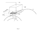
- FIG. 2 is a schematic of a phased array probe, free of the probe holder shown in FIG. 1 , and arranged in the manner of the preferred embodiment over a cylindrical part to inspect.
- FIG. 3 is a schematic of a 9 ⁇ N elemental transducers array in a 1.5 D configuration as found under the configuration of FIG. 2 .
- FIG. 4 is a schematic cross section view along the elevation axis of one column of transducers found in FIG. 3 of the concentric firing pattern put forward by the preferred.
- FIG. 5 is a schematic cross section view along the elevation axis of one column of transducers found in FIG. 3 of the time average envelope of the acoustic field for two aperture sizes.
- FIG. 6 is a flowchart of the method according to the preferred embodiment.
- the method proposed by the preferred embodiment is presented from a hierarchical high level-low level perspective.
- FIG. 1 a conceptual view of a subset of an inspection system for cylindrical parts is shown.
- the depicted cylindrical part 111 is a tube of outer diameter 112 .
- the complete inspection system 107 provides a way to rotate the cylindrical part with respect to the probes for complete coverage by the PA probes.
- a control module 106 directs the appropriate cylindrical part parameters and inspection range to an aperture optimization module 105 that optimizes through computation the aperture size along the elevation axis according to the intended inspection parameters.
- the optimal aperture parameters are then sent to a concentric delay module 104 that readies the delay-based concentric firing pattern for the computed aperture.
- the prepared focal law is then inputted in the acquisition unit 103 that serves as a two-way input-output 102 device for enabling ultrasound emission and reception from PA probes located inside a probe holder 101 .
- the received inspection data is then sent back to the control module 106 for further processing.
- a phased array probe enclosed inside the probe holder 101 is presented in FIG. 2 together with a section of an inspected cylindrical part 111 (depicted is a tube section).
- the transducer array 2010 embedded within the probe housing 202 is electronically reached through the uplink 203 , itself connected to the acquisition device 104 .
- the array itself is composed of columns of transducers such as 2011 and 2012 along the scan axis 212 .
- the perpendicular axis to the scan axis is the elevation axis 211 .
- the elevation axis is perpendicular to the cylindrical part axis, whereas the scan axis is parallel to the cylindrical part axis.
- the challenge that is met by the present method according to the preferred embodiment is to adapt the acoustic beam formed along the elevation axis 211 by each column of transducers 2011 , 2012 , . . . to the cylindrical part diameter 112 and near-surface inspection range 113 given a constant probe-to-part distance 210 .
- the volume separating the probe within the probe holder and the cylindrical part surface is filled with an appropriate acoustic coupling material.
- the present method makes use of a 1.5D array of transducers, a section of which is schematically represented on FIG. 3 , to achieve the fore mentioned objective.
- This array comprise a matrix of individual transducers 3011 - a , 3011 - b - 1 , 3011 - b - 2 . . . 3012 - a , 3012 - b - 1 , 3012 - b - 2 . . . along the rows of the elevation axis 211 and the columns 3011 , 3012 . . . along the scan axis 212 .
- each column say column 3011
- the elemental transducers are electronically grouped in pairs 3011 - b - 1 and 3011 - b - 2 , . . . , 3011 - e - 1 and 3011 - e - 2 through the leads 3011 -B, . . . , 3011 -E respectively.
- Only the center element 3011 - a has its own lead 3011 -A.
- the transducer array may possess any number of rows or columns: FIG. 3 depicts an array of 9 rows only for the sake of illustration.
- the 1.5D array is operated using two collaborating effects.
- the first one is the on-time arrival on the cylindrical part surface of the pulsed acoustic field emitted from every elemental transducer.
- This effect is related to the firing pattern as presented on FIG. 4 where a common cross section of the probe housing 202 , of the transducer array at the level of column 3011 , and of the cylindrical part 111 is presented.
- the firing sequence of a column of transducers is triggered as to form a series of acoustic pulses 401 that fall on a common arc of circle 403 positioned at the same minimum time of flight from the cylindrical part surface 402 .
- the arc of circle 403 is concentrical to the cylindrical part 111 and is thereof adapted to the probe-to-part distance 210 . This in turn is done by activating with adequate time delays the elements of the array through the electronic leads 3011 -A, . . . , 3011 -E of FIG. 3 . Following this configuration, since the pulsed acoustic field arrives simultaneously in time at the cylindrical bar interface, the front wall reflection echo reaches the probe with the same delays as the ones used for building the concentric firing pattern. This accounts for the sharp and coherent front wall reflection echo.
- the second effect to consider is the impact of the probe aperture size on the intensity profile of the acoustic field.
- a conceptual representation of this is shown on FIG. 5 where a common cross section of the probe housing 202 , of the enclosed array at the level of column 3011 , and of the cylindrical part 111 is presented.
- the envelope of the time averaged forward propagating acoustic field 502 has a maximum (modulus of) intensity distribution 503 at the farthest achievable position from the probe.
- Any smaller aperture size, 504 for instance produces a field envelope 505 whose maximum intensity distribution 506 is closer to the array.
- the present method is suitable to carry out improved material inspection using a single mechanical configuration of the inspection system over both a range of cylindrical part diameters and a range of inspection domains.
- the overall method is summarized in the flowchart presented on FIG. 6 .
- the main inputs for a successful implementation of the preferred embodiment are the cylindrical part diameter and intended range of inspection 601 , the 1.5 D probe characteristics 602 and the current probe-to-part distance 603 .
Landscapes
- Physics & Mathematics (AREA)
- Health & Medical Sciences (AREA)
- Life Sciences & Earth Sciences (AREA)
- Chemical & Material Sciences (AREA)
- Analytical Chemistry (AREA)
- Biochemistry (AREA)
- General Health & Medical Sciences (AREA)
- General Physics & Mathematics (AREA)
- Immunology (AREA)
- Pathology (AREA)
- Acoustics & Sound (AREA)
- Investigating Or Analyzing Materials By The Use Of Ultrasonic Waves (AREA)
Abstract
Description
Claims (6)
Priority Applications (1)
| Application Number | Priority Date | Filing Date | Title |
|---|---|---|---|
| US13/853,764 US9080951B2 (en) | 2013-03-29 | 2013-03-29 | Method and system of using 1.5D phased array probe for cylindrical parts inspection |
Applications Claiming Priority (1)
| Application Number | Priority Date | Filing Date | Title |
|---|---|---|---|
| US13/853,764 US9080951B2 (en) | 2013-03-29 | 2013-03-29 | Method and system of using 1.5D phased array probe for cylindrical parts inspection |
Publications (2)
| Publication Number | Publication Date |
|---|---|
| US20130283918A1 US20130283918A1 (en) | 2013-10-31 |
| US9080951B2 true US9080951B2 (en) | 2015-07-14 |
Family
ID=49476167
Family Applications (1)
| Application Number | Title | Priority Date | Filing Date |
|---|---|---|---|
| US13/853,764 Expired - Fee Related US9080951B2 (en) | 2013-03-29 | 2013-03-29 | Method and system of using 1.5D phased array probe for cylindrical parts inspection |
Country Status (1)
| Country | Link |
|---|---|
| US (1) | US9080951B2 (en) |
Families Citing this family (13)
| Publication number | Priority date | Publication date | Assignee | Title |
|---|---|---|---|---|
| JP2016042043A (en) * | 2014-08-15 | 2016-03-31 | 出光興産株式会社 | Outer shell corrosion inspection apparatus and outer shell corrosion inspection method |
| US10085718B2 (en) | 2015-01-30 | 2018-10-02 | Noble Sensors, Llc | Ultrasonic probe with a beam having an ultrasonic transducer |
| EP3265836A4 (en) * | 2015-03-06 | 2018-12-26 | Noble Sensors, LLC | System and method for phased array material imaging |
| US9778231B2 (en) * | 2015-05-13 | 2017-10-03 | Spirit Aerosystems, Inc. | Ultrasonic inspection end effector |
| CN105259253B (en) * | 2015-11-06 | 2018-09-07 | 国网山东省电力公司电力科学研究院 | A kind of phased array detection method of main inlet throttle-stop valve valve rod |
| CN106182154B (en) * | 2016-07-14 | 2019-03-15 | 长园和鹰智能科技有限公司 | A kind of cutting device intelligence sharpening system and its intelligent sharpening method |
| DE102018005540B4 (en) | 2018-07-13 | 2022-06-09 | Pepperl+Fuchs Ag | 1D ultrasonic transducer unit |
| DE102018006139B3 (en) | 2018-08-03 | 2019-06-19 | Pepperl+Fuchs Gmbh | 1D ultrasonic transducer unit for area monitoring |
| DE102018006127B4 (en) | 2018-08-03 | 2021-07-08 | Pepperl+Fuchs Ag | 1D ultrasonic transducer unit for material detection |
| DE102018006130B3 (en) * | 2018-08-03 | 2019-08-08 | Pepperl + Fuchs Gmbh | 1D ultrasonic transducer unit for hazard detection for a vehicle |
| US11628470B2 (en) | 2019-06-14 | 2023-04-18 | United States Of America As Represented By The Secretary Of The Air Force | Method for locating elements on a flexible ultrasound phased array |
| GB201911201D0 (en) * | 2019-08-06 | 2019-09-18 | Darkvision Tech | Methods and apparatus for coiled tubing inspection by ultrasound |
| CN113686960B (en) * | 2021-08-17 | 2022-11-04 | 武汉理工大学 | Phased array curved surface full-focusing imaging optimization method and system for sound field threshold segmentation |
Citations (5)
| Publication number | Priority date | Publication date | Assignee | Title |
|---|---|---|---|---|
| US6524254B2 (en) * | 2001-06-20 | 2003-02-25 | Bae Systems Information And Electronic Systems Integration, Inc. | Orthogonally reconfigurable integrated matrix acoustical array |
| US6789427B2 (en) * | 2002-09-16 | 2004-09-14 | General Electric Company | Phased array ultrasonic inspection method for industrial applications |
| US6813950B2 (en) * | 2002-07-25 | 2004-11-09 | R/D Tech Inc. | Phased array ultrasonic NDT system for tubes and pipes |
| US7338450B2 (en) * | 2004-08-27 | 2008-03-04 | General Electric Company | Method and apparatus for performing CW doppler ultrasound utilizing a 2D matrix array |
| US7431698B2 (en) * | 2004-01-13 | 2008-10-07 | Ge Medical Systems Global Technology Company, Llc | Apparatus and method for controlling an ultrasound probe |
-
2013
- 2013-03-29 US US13/853,764 patent/US9080951B2/en not_active Expired - Fee Related
Patent Citations (5)
| Publication number | Priority date | Publication date | Assignee | Title |
|---|---|---|---|---|
| US6524254B2 (en) * | 2001-06-20 | 2003-02-25 | Bae Systems Information And Electronic Systems Integration, Inc. | Orthogonally reconfigurable integrated matrix acoustical array |
| US6813950B2 (en) * | 2002-07-25 | 2004-11-09 | R/D Tech Inc. | Phased array ultrasonic NDT system for tubes and pipes |
| US6789427B2 (en) * | 2002-09-16 | 2004-09-14 | General Electric Company | Phased array ultrasonic inspection method for industrial applications |
| US7431698B2 (en) * | 2004-01-13 | 2008-10-07 | Ge Medical Systems Global Technology Company, Llc | Apparatus and method for controlling an ultrasound probe |
| US7338450B2 (en) * | 2004-08-27 | 2008-03-04 | General Electric Company | Method and apparatus for performing CW doppler ultrasound utilizing a 2D matrix array |
Also Published As
| Publication number | Publication date |
|---|---|
| US20130283918A1 (en) | 2013-10-31 |
Similar Documents
| Publication | Publication Date | Title |
|---|---|---|
| US9080951B2 (en) | Method and system of using 1.5D phased array probe for cylindrical parts inspection | |
| JP5721770B2 (en) | Ultrasonic flaw detection method and apparatus | |
| JP5590249B2 (en) | Defect detection apparatus, defect detection method, program, and storage medium | |
| JP2013156277A (en) | Ultrasonic flaw detection method and device thereof | |
| CN102047106B (en) | Method and device for the non-destructive ultrasonic testing of a test piece with flat surfaces at an angle to each other | |
| CN102282462B (en) | Ultrasonic flaw detection method and device | |
| JP5889742B2 (en) | Ultrasonic flaw detection apparatus and method | |
| CN105738478B (en) | Imaging method is detected based on the steel plate Lamb wave that linear array focal time is inverted | |
| WO2015053014A1 (en) | Probe, ultrasonic flaw detection apparatus, and ultrasonic flaw detection control method | |
| JP6926011B2 (en) | Ultrasonic flaw detector and ultrasonic flaw detection method | |
| JP2009540311A (en) | Ultrasonic testing equipment with array probe | |
| CN101622534B (en) | Ultrasonic inspection equipment | |
| US20210048413A1 (en) | Fast pattern recognition using ultrasound | |
| JP4564867B2 (en) | Ultrasonic flaw detection method and apparatus | |
| JP5115024B2 (en) | Coupling check method for ultrasonic oblique angle flaw detector | |
| JP6871534B2 (en) | Comparison test piece and ultrasonic phased array flaw detection test method | |
| JP2014535034A (en) | Device for non-destructive inspection of a test object by ultrasound, method for operating such a device, and method for non-destructive inspection of a test object by ultrasound | |
| JP4633268B2 (en) | Ultrasonic flaw detector | |
| KR100970948B1 (en) | 2-dimensional virtual array probe for 3-dimensional ultrasonic imaging | |
| JP6517539B2 (en) | Ultrasonic flaw detection apparatus and method | |
| JP2014232044A (en) | Ultrasonic flaw detection device, method, and program | |
| JP5709357B2 (en) | Ultrasonic flaw detection apparatus and ultrasonic flaw detection method | |
| Zhou et al. | Effects of directivity function on total focusing method imaging performance | |
| Bardouillet | Application of electronic focussing and scanning systems to ultrasonic testing | |
| Berke et al. | Phased array technology for standard ultrasonic testing. |
Legal Events
| Date | Code | Title | Description |
|---|---|---|---|
| AS | Assignment |
Owner name: OLYMPUS NDT INC., MASSACHUSETTS Free format text: ASSIGNMENT OF ASSIGNORS INTEREST;ASSIGNORS:HABERMEHL, JASON;ZHANG, JINCHI;REEL/FRAME:030817/0037 Effective date: 20130715 |
|
| STCF | Information on status: patent grant |
Free format text: PATENTED CASE |
|
| MAFP | Maintenance fee payment |
Free format text: PAYMENT OF MAINTENANCE FEE, 4TH YEAR, LARGE ENTITY (ORIGINAL EVENT CODE: M1551); ENTITY STATUS OF PATENT OWNER: LARGE ENTITY Year of fee payment: 4 |
|
| AS | Assignment |
Owner name: OLYMPUS SCIENTIFIC SOLUTIONS AMERICAS INC., MASSACHUSETTS Free format text: CHANGE OF NAME;ASSIGNOR:OLYMPUS NDT INC.;REEL/FRAME:062732/0498 Effective date: 20140401 |
|
| FEPP | Fee payment procedure |
Free format text: MAINTENANCE FEE REMINDER MAILED (ORIGINAL EVENT CODE: REM.); ENTITY STATUS OF PATENT OWNER: LARGE ENTITY |
|
| AS | Assignment |
Owner name: OLYMPUS AMERICA INC., PENNSYLVANIA Free format text: MERGER;ASSIGNOR:OLYMPUS SCIENTIFIC SOLUTIONS AMERICAS INC.;REEL/FRAME:063112/0940 Effective date: 20160404 |
|
| LAPS | Lapse for failure to pay maintenance fees |
Free format text: PATENT EXPIRED FOR FAILURE TO PAY MAINTENANCE FEES (ORIGINAL EVENT CODE: EXP.); ENTITY STATUS OF PATENT OWNER: LARGE ENTITY |
|
| STCH | Information on status: patent discontinuation |
Free format text: PATENT EXPIRED DUE TO NONPAYMENT OF MAINTENANCE FEES UNDER 37 CFR 1.362 |
|
| FP | Lapsed due to failure to pay maintenance fee |
Effective date: 20230714 |
|
| AS | Assignment |
Owner name: EVIDENT SCIENTIFIC, INC., MASSACHUSETTS Free format text: CONFIRMATORY ASSIGNMENT;ASSIGNOR:OLYMPUS AMERICA INC.;REEL/FRAME:066143/0724 Effective date: 20231130 |