EP3806600A1 - Replacement system and replacement device - Google Patents
Replacement system and replacement device Download PDFInfo
- Publication number
- EP3806600A1 EP3806600A1 EP18920492.8A EP18920492A EP3806600A1 EP 3806600 A1 EP3806600 A1 EP 3806600A1 EP 18920492 A EP18920492 A EP 18920492A EP 3806600 A1 EP3806600 A1 EP 3806600A1
- Authority
- EP
- European Patent Office
- Prior art keywords
- replacement
- detecting section
- feeder
- replacement element
- component mounting
- Prior art date
- Legal status (The legal status is an assumption and is not a legal conclusion. Google has not performed a legal analysis and makes no representation as to the accuracy of the status listed.)
- Pending
Links
Images



Classifications
-
- H—ELECTRICITY
- H05—ELECTRIC TECHNIQUES NOT OTHERWISE PROVIDED FOR
- H05K—PRINTED CIRCUITS; CASINGS OR CONSTRUCTIONAL DETAILS OF ELECTRIC APPARATUS; MANUFACTURE OF ASSEMBLAGES OF ELECTRICAL COMPONENTS
- H05K13/00—Apparatus or processes specially adapted for manufacturing or adjusting assemblages of electric components
- H05K13/02—Feeding of components
- H05K13/021—Loading or unloading of containers
-
- H—ELECTRICITY
- H05—ELECTRIC TECHNIQUES NOT OTHERWISE PROVIDED FOR
- H05K—PRINTED CIRCUITS; CASINGS OR CONSTRUCTIONAL DETAILS OF ELECTRIC APPARATUS; MANUFACTURE OF ASSEMBLAGES OF ELECTRICAL COMPONENTS
- H05K13/00—Apparatus or processes specially adapted for manufacturing or adjusting assemblages of electric components
- H05K13/04—Mounting of components, e.g. of leadless components
- H05K13/0417—Feeding with belts or tapes
Definitions
- the present invention relates to replacement systems and replacement devices.
- Patent Literature 1 discloses a replacement device as a replenishment device that automatically collects and replenishes feeders with a component mounting machine.
- a replacement device for example, is capable of detecting feeders in an accommodated state with a detection sensor provided in the device main body, and, based on detection results from the detection sensor, can recognize whether a feeder is being accommodated in the device main body or has been installed in the component mounting machine.
- Patent Literature 1 International Publication WO2014/010083
- the present specification discloses a replacement system, comprising: a device main body configured to contain a replacement element detachably installed in a component mounting machine; a holding portion configured to hold the replacement element and provided in the device main body so as to be movable in an attachment/detachment direction of the replacement element; a first detecting section and a second detecting section, each configured to detect the replacement element at different detection positions in the attachment/detachment direction of the replacement element; and a determination section configured to determine whether the replacement process of the replacement element between the device main body and the component mounting machine has been performed in a normal manner based on the detection result from the first detecting section and the detection result from the second detecting section.
- a replacement device comprising: a device main body configured to contain a replacement element detachably installed in a component mounting machine; a holding portion configured to hold the replacement element and provided in the device main body so as to be movable in an attachment/detachment direction of the replacement element; a first detecting section, provided in the device main body, configured to detect the replacement element at a predetermined detection position in the attachment/detachment direction of the replacement element; and a determination section configured to determine whether the replacement process of the replacement element between the device main body and the component mounting machine has been performed in a normal manner based on the detection result from a second detecting section and the detection result from the first detecting section, the second detecting section being provided in the component mounting machine and configured to detect the replacement element at a detection position, in the attachment/detachment direction of the replacement element, different from the detection position of the first detecting section.
- the replacement element is detected at different detection positions in the attachment/detachment direction by the first detecting section and the second detecting section. As a result, it is possible to more accurately determine the state of a replacement element undergoing a replacement process. Therefore, it is possible to determine whether a replacement process has been successful.
- the replacement system comprising the replacement device is intended for at least one of the various replacement elements provided in the component mounting machine and exchanges the replacement elements with the component mounting machine.
- a mode in which the replacement system is applied to a production line configured with multiple component mounting machines will be used as an example.
- Production line 1 is configured with multiple component mounting machine 10 installed side by side in the conveyance direction of board 90 (X-direction).
- Feeder storage device 5 used for storage of feeders 20 of the cassette type is installed at the board convey-in side of production line 1 (upper left side in Fig. 1 ).
- Production line 1 may also include, for example, screen printers, mounting inspection machines, reflow furnaces, and the like.
- replacement device 50 as a work device for performing a predetermined operation on each of multiple component mounting machines 10 and feeder storage device 5, is applied to production line 1.
- Each of the devices constituting production line 1 and replacement device 50 are configured to input and output various data to and from management device 6 via a network (not shown). A detailed configuration of replacement device 50 will be described later.
- Feeder storage device 5 has multiple slots and stocks feeders 20 set in the slots.
- feeder 20 is set in feeder storage device 5
- communication between feeder 20 and management device 6 is enabled.
- the slot of feeder storage device 5 and ID of feeder 20 set in the slot are linked to each other and recorded in management device 6.
- Management device 6 monitors the operational status of production line 1 and controls the production equipment including component mounting machines 10 and feeder storage device 5. Various data for controlling component mounting machines 10 are stored in management device 6. Management device 6 transmits various data such as a control program to each piece of production equipment as appropriate when executing the production process in each piece of production equipment.
- Each of multiple component mounting machines 10 constituting production line 1, as shown in Figs. 2 and 3 comprise board conveyance device 11, component supply device 12, head driving device 13, part camera 14, board camera 15, and height sensor 16.
- the conveyance direction of board 90 which is the horizontal width direction of component mounting machine 10 is the X-direction
- the horizontal depth direction of component mounting machine 10 is the Y-direction
- the vertical direction perpendicular to the X-direction and the Y-direction (the up-down direction in Fig. 1 ) is the Z-direction.
- Board conveyance device 11 includes a belt conveyor, a positioning device, and the like. Board conveyance device 11, together with sequentially conveying board 90 in the conveyance direction, positions board 90 at a predetermined position in the machine. Board conveyance device 11 conveys board 90 out of component mounting machine 10 after the mounting process by component mounting machine 10 is completed.
- Component supply device 12 supplies a component to be mounted on board 90.
- Component supply device 12 has upper slots 121 and lower slots 122 which can be installed with feeders 20.
- Upper slots 121 are disposed on the top of the front side of component mounting machine 10 and holds installed feeders 20 in an operational manner. That is, the operation of feeders 20 installed in upper slots 121 is controlled in the mounting process in component mounting machine 10, and components are supplied from a retrieving portion provided in a predetermined position of the upper portion of feeder 20.
- Lower slots 122 are located below upper slots 121 and stock installed feeders 20. That is, lower slots 122 preliminarily hold feeders 20 used in production or temporarily hold used feeders 20 that were used in production. The exchange of feeders 20 between upper slots 121 and lower slots 122 is performed by automatic exchange by replacement device 50 to be described later, or manual exchange by an operator.
- Head driving device 13 transfers components supplied by component feeder 12 to a predetermined mounting position on board 90 conveyed in by board conveyance device 11.
- Head driving device 13 moves moving table 131 in the horizontal direction (X-axis direction and Y-axis direction) by a linear motion mechanism.
- Mounting head 30 is fixed to moving table 131 in an exchangeable manner by a clamp member (not shown). In addition to picking up components, mounting head 30 adjusts the up-down directional position and angle of components and mounts the components on board 90.
- a holding member for holding components supplied by feeder 20 is attached to mounting head 30.
- suction nozzle 31 that is supplied with negative pressure and holds components, a chuck that grips and holds components, or the like can be applied to the holding member.
- Mounting head 30 can move the holding member in the Z-direction and can rotate the holding member around a ⁇ axis that is parallel to the Z-axis.
- Mounting head 30 is moved in the XY-direction by a linear motion mechanism of head driving device 13.
- Part camera 14 and board camera 15 are digital imaging devices having an imaging device such as a CMOS. Part camera 14 and board camera 15 perform imaging based on control signals and send image data acquired by the imaging. Part camera 14 is configured to image components held by suction nozzle 31 of mounting head 30 from below. Board camera 15 is configured to image board 90 from above.
- Height sensor 16 is provided on moving table 131. Height sensor 16 measures the height from a target object to mounting head 30 by measuring the distance to the target object located vertically below. Height sensor 16 may be, for example, an optical sensor utilizing a laser beam. Further, the target object described above, for example, can include board 90 positioned by board conveyance device 11, components mounted on board 90, such as components supplied by component supply device 12, and the like.
- Component mounting machine 10 having the above-described configuration executes a mounting process for mounting a component to board 90.
- component mounting machine 10 sends a control signal to head driving device 13 based on the result of image processing, detection results from various sensors, a control program stored in advance, and the like. With this, the position and angle of multiple suction nozzles 31 supported by mounting head 30 are controlled.
- Suction nozzle 31 to be held in mounting head 30 is appropriately changed in accordance with the type of component to be mounted on board 90 in the mounting process.
- Component mounting machine 10 causes mounting head 30 to pick up suction nozzle 31 accommodated in nozzle station 35 when suction nozzle 31 used in the mounting process to be executed is not held by mounting head 30.
- Nozzle station 35 described above is detachably installed in a predetermined position inside component mounting machine 10.
- Feeder 20 feeds and moves a carrier tape containing a large number of components such that components are supplied in a manner which allows the components to be picked up.
- Case 21 of feeder 20 has an overall rectangular shape. Case 21 detachably holds tape reel 23 on which carrier tape 22 is wound.
- Carrier tape 22 accommodates components in multiple cavities formed at regular intervals in the feeding direction.
- feeder 20 when feeder 20 is installed in upper slot 121 or lower slot 122 of component supply device 12, power is supplied from component mounting machine 10 via a connector. Feeder 20 is then able to communicate with component mounting machine 10. Feeder 20 controls the feeding operation of carrier tape 22 based on control instructions from component mounting machine 10 or the like. Thus, feeder 20 supplies components in a manner which allows the components to be picked up by the holding member of mounting head 30 in the retrieving portion provided at a predetermined position of the upper portion of feeder 20.
- Replacement system 40 includes first rail 41, second rail 42, and replacement device 50, as shown in Figs. 1 to 3 .
- First rail 41 as shown in Fig. 1 , is provided at the front of multiple component mounting machine 10. More specifically, first rail 41 is provided between upper slots 121 and lower slots 122, in the up-down direction, upper slots 121 and lower slots 122 being provided at each of the multiple component mounting machines 10.
- Second rail 42 is provided below lower slots 122 of component mounting machine 10.
- First rail 41 and second rail 42 extend over substantially the entire length of the conveyance direction of board 90 in production line 1.
- replacement device 50 by an operation of moving device 53 to be described later, is configured to be positioned at any position in the X-direction including the front of component mounting machines 10 and feeder storage device 5.
- replacement device 50 performs a replacement process of feeder 20 with multiple component mounting machines 10 and feeder storage device 5 which constitute production line 1.
- the replacement process described above includes at least one of recovery and replenishment of feeder 20.
- replacement device 50 conveys feeder 20 from feeder storage device 5 to upper slot 121 or lower slot 122 of component mounting machine 10. Replacement device 50 also exchanges feeder 20 between upper slot 121 and lower slot 122 of component mounting machine 10. Furthermore, replacement device 50 conveys used feeders 20 from component mounting machine 10 to feeder storage device 5.
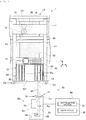
- Replacement device 50 includes, as shown in Fig. 3 , device main body 51, holding portion 52, moving device 53, reference sensor 54, and control device 60.
- Device main body 51 accommodates feeder 20 and holds holding portion 52. Further, a driving device (not shown) for operating holding portion 52 is provided in device main body 51.
- Holding portion 52 holds feeder 20. As for configurations by which holding portion 52 is to hold feeder 20, holding portion 52 can be configured to grip case 21 of feeder 20, holding portion 52 can be configured to lock a locking portion provided in case 21, holding portion 52 can be configured to connect to a connecting portion provided in case 21, and the like.
- Holding portion 52 is provided to device main body 51 so as to be movable in the attachment/detachment direction of feeder 20 (Y-direction in this embodiment). Further, holding portion 52 is provided so as to be movable in the Z-direction with respect to device main body 51. The YZ-direction position of holding portion 52 and holding state of feeder 20 by holding portion 52 is controlled by control device 60.
- Moving device 53 moves device main body 51 along the conveyance direction of board 90 in production line 1 (X-direction in this embodiment).
- Moving device 53 moves device main body 51 along first rail 41 by rotating a drive wheel (not shown) which is frictionally engaged with first rail 41. As this occurs, moving device 53 maintains the orientation of device main body 51 with a guide roller (not shown) which rolls along second rail 42.
- the X-direction position of moving device 53 is controlled by control device 60.
- Reference sensor 54 detects the accommodated state of feeder 20 in device main body 51.
- the "accommodated state” refers to a state in which feeder 20 is moved to accommodating position Pa in the attachment/detachment direction (Y-direction), as indicated by the one-dot chain line in Fig. 3 .
- reference sensor 54 is a proximity sensor provided to holding portion 52. In a non-contact manner, reference sensor 54 detects feeder 20 moved to accommodating position Pa. Reference sensor 54 does not detect feeder 20 in the case where feeder 20 in the attachment/detachment direction of feeder 20 is positioned deviated from accommodating position Pa and in the case where holding portion 52 does not hold feeder 20.
- Control device 60 is a controller mainly composed of a CPU, various types of memory, and a control circuit. Control device 60 is communicatively connected to multiple component mounting machines 10, feeder storage device 5, and management device 6. Control device 60 operates the driving device for operating moving device 53 and holding portion 52 based on the X-direction position of device main body 51, the YZ direction position of holding portion 52, the holding state of feeder 20, and the like. Thus, control device 60 controls the replacement process of feeder 20 by replacement device 50.
- feeder 20 When replacement process of feeder 20 by replacement device 50 is performed in a normal manner, feeder 20 assumes a state of being accommodated in device main body 51 or a state of being installed in component mounting machine 10.
- control device 60 After performing the replacement process, control device 60 recognizes whether feeder 20 is positioned in accommodating position Pa based on the detection result from reference sensor 54.
- replacement system 40 is configured to detect feeder 20 at different detection positions from each other in the attachment/detachment direction of feeder 20 and determine whether the replacement process has been performed in a normal manner based on the detection result.
- replacement system 40 includes first detecting section 71, second detecting section 72, determination section 61, and guide section 62.
- First detecting section 71 and second detecting section 72 detect feeder 20 at detection positions D1,D2 different from each other in the attachment/detachment direction of feeder 20.
- first detecting section 71 has optical sensor 711 as a first sensor provided in device main body 51.
- second detecting section 72 has optical sensor 721 as a second sensor provided in component mounting machine 10.
- optical sensors 711,721 receive light emitted in a direction (X-direction in this embodiment) intersecting the attachment/detachment direction of feeder 20 and detect the presence/absence of feeder 20 in the detection position.
- optical sensor 711 of first detecting section 71 detects feeder 20 at first detection position D1 separated by predetermined distance L1 toward the installation position Pe side from the end of feeder 20 located at accommodating position Pa (refer to states Y1,Y2 in Fig. 4 ).
- optical sensor 721 of second detecting section 72 detects feeder 20 at second detection position D2 separated by predetermined distance L2 toward the accommodating position Pa side from the end of feeder 20 located at installation position Pe (refer to states Y4,Y5 in Fig. 4 ).
- first detecting section 71 detects any protrusion of feeder 20 from device main body 51. Further, second detecting section 72 detects any protrusion of feeder 20 from component mounting machine 10.
- the detection width of optical sensor 721 of second detecting section 72 is set wider than the X-direction width of upper slots 121.
- second detecting section 72 is configured to detect feeder 20 protruding from any one of upper slots 121.
- distance Ld between first detection position D1 and second detection position D2 is set smaller than length Lf of feeder 20.
- determination section 61 and guide section 62 are incorporated in control device 60 of replacement device 50.
- Determination section 61 determines whether the replacement process of feeder 20 between device main body 51 and component mounting machine 10 has been performed in a normal manner based on the detection result from first detecting section 71 and the detection result from second detecting section 72. More specifically, determination section 61 determines that the replacement process has been abnormally terminated without having been performed in a normal manner in the case where only first detecting section 71 detects feeder 20 as shown in state Y2 of Fig. 4 ; in the case where both first detecting section 71 and second detecting section 72 detect feeder 20 as shown in state Y3 of Fig. 4 ; and in the case where only second detecting section 72 detects feeder 20 as shown in state Y4 of Fig. 4 .
- determination section 61 determines that the replacement process has been performed in a normal manner when both the detection result from first detecting section 71 and the detection result from second detecting section 72 indicate that feeder 20 is not detected.
- Fig. 4 displays each of the states of the same feeder 20 shifted in the X-direction. Therefore, the X-direction positions of feeders 20 in the states Y1 to Y5 of Fig. 4 are the same.
- Guide section 62 notifies the operator of the state of feeder 20 recognized based on the detection result from first detecting section 71 and the detection result from second detecting section 72 in the case where determining section 61 determines that the replacement process of feeder 20 has not been performed in a normal manner.
- the above “state of feeder 20" includes the position of feeder 20 in the attachment/detachment direction, whether holding portion 52 holds feeder 20, whether feeder 20 is communicable with component mounting machine 10, and the like.
- guide section 62 indicates the position of feeder 20 to be determined based on the detection result from first detecting section 71 and the detection result from second detecting section 72. In addition to or in place of the state of feeder 20 as described above, guide section 62 may notify the operator with error processing information.
- the information of error processing indicates restoration work or the like for the replacement process which has been abnormally terminated, and is changed in accordance with the state of feeder 20.
- Guide section 62 may display guidance information on management device 6 or display guidance information on a terminal device such as a portable terminal (smartphone, tablet) held by an operator.
- a terminal device such as a portable terminal (smartphone, tablet) held by an operator.
- the replacement process by the replacement system will be described with reference to Figs. 4 and 5 .
- the replacement element which is the target of the replacement process is feeder 20 which is installed in component mounting machine 10 in the same manner as described above.
- the replacement process includes a replenishment operation of installing feeder 20 from device main body 51 of replacement device 50 to upper slot 121 or lower slot 122 of component supply device 12, and, conversely, a recovery operation of withdrawing feeder 20 from component supply device 12 by device main body 51.
- the replenishment operation in the replacement process will now be described.
- replacement device 50 puts feeder 20 from feeder storage device 5 or lower slot 122 of component supply device 12 into an accommodated state in device main body 51, feeder 20 being scheduled for installation.
- Control device 60 recognizes that feeder 20 is in a normal accommodated state based on reference sensor 54 detecting feeder 20 held by holding portion 52 and the two optical sensors 711,721 not detecting feeder 20.
- control device 60 first performs positioning of replacement device 50 (S11). Specifically, control device 60 causes moving device 53 to operate based on the current position of replacement device 50 in the X-direction. As a result, feeder 20 held by holding portion 52 is positioned corresponding to the position of upper slot 121 scheduled for installation. Next, control device 60 causes holding portion 52 to operate, causing feeder 20 held by holding portion 52 to move to installation position Pe (S12).
- control device 60 releases the holding of feeder 20 by holding portion 52 and returns holding portion 52 to the device main body 51 side (S13).
- Determination section 61 determines whether the replacement process of feeder 20 between device main body 51 and component mounting machine 10 has been performed in a normal manner based on the detection result from first detecting section 71 and the detection result from second detecting section 72 (S14). Specifically, assuming that reference sensor 54 does not detect feeder 20 because the replenishment operation has been performed, in the case where first detecting section 71 and second detecting section 72 both do not detect feeder 20 (state Y1 or state Y5 in Fig. 4 ), determination section 61 determines that the replacement process has been performed in a normal manner (S14: Yes).
- determination section 61 determines that the replacement process has been abnormally terminated without having been performed in a normal manner (S14: No).
- Control device 60 executes error processing in the case where the replacement process has been abnormally terminated (S15).
- operation from the current state is restricted in replacement device 50 together with the stopping of operation of holding portion 52 and moving device 53.
- guide section 62 provides the state of feeder 20 and information on error processing (S16). Specifically, with the state of feeder 20 being the position of feeder 20 calculated based on the detection result from first detecting section 71 and the detection result from second detecting section 72, guide section 62 provides the operator with the position of feeder 20 in the installation operation of the replacement process. Furthermore, guide section 62 suggests restoration work in accordance with the state of feeder 20.
- Replacement system 40 comprises: device main body 51 configured to contain a replacement element (feeder 20) detachably installed in component mounting machine 10; holding portion 52 configured to hold the replacement element and provided in device main body 51 so as to be movable in the attachment/detachment direction of the replacement element; first detecting section 71 and second detecting section 72, each configured to detect the replacement element at different detection positions in the attachment/detachment direction of the replacement element; and determination section 61 configured to determine whether the replacement process of the replacement element between device main body 51 and component mounting machine 10 has been performed in a normal manner based on the detection result of first detecting section 71 and the detection result of second detecting section 72.
- replacement device 50 comprises: device main body 51 configured to contain a replacement element (feeder 20) detachably installed in component mounting machine 10; holding portion 52 configured to hold the replacement element and provided in device main body 51 so as to be movable in the attachment/detachment direction of the replacement element; first detecting section 71, provided in device main body 51, configured to detect the replacement element at a predetermined detection position in the attachment/detachment direction of the replacement element; determination section 61 configured to determine whether the replacement process of the replacement element between device main body 51 and component mounting machine 10 has been performed in a normal manner based on the detection result of second detecting section 72 and the detection result from first detecting section 71, second detecting section 72 being provided in component mounting machine 10 and configured to detect the replacement element at a detection position, in the attachment/detachment direction of the replacement element, different from the detection position of first detecting section 71.
- the replacement element (feeder 20) is detected at different detection positions D1, D2 in the attachment/detachment direction by first detecting section 71 and second detecting section 72.
- first detecting section 71 is provided in device main body 51 of replacement device 50 and second detecting section 72 is provided in component mounting machine 10.
- first detecting section 71 and second detecting section 72 may adopt various modes as long as they can detect feeder 20 at detection positions D1 ,D2 different from each other in the attachment/detachment direction of feeder 20.
- both first detecting section 71 and second detecting section 72 may be provided in replacement device 50.
- replacement device 50 is provided with moving device 53, it is possible to share first detecting section 71 and second detecting section 72 in the replacement process among multiple component mounting machines 10 and feeder storage device 5.
- first detecting section 71 and second detecting section 72 may be provided in component mounting machine 10. As a result, the positional relationship between first detecting section 71 and second detecting section 72 is fixed, and detection accuracy can be improved.
- first detecting section 71 and second detecting section 72 have optical sensors 711,721.
- first detecting section 71 and second detecting section 72 may be configured to have a contact sensor or an ultrasonic sensor.
- Second detecting section 72 may be configured as a second sensor in component mounting machine 10 and serve as height sensor 16 of component mounting machine 10.
- replacement device 50 makes a request to component mounting machine 10 so that height sensor 16 is moved to a position above feeder 20 and detects the height of feeder 20.
- second detection position D2 may be a position shifted toward the accommodating position Pa side from feeder 20 positioned at installation position Pe.
- Second detecting section 72 detects feeder 20 based on the detection result of height sensor 16.
- first detecting section 71 and second detecting section 72 may detect feeder 20 based on the result of image processing. Specifically, instead of optical sensors 711,721, first detecting section 71 and second detecting section 72 detect feeder 20 by image processing image data acquired by imaging with a camera including the detection position in the camera field of view. As a result, determination section 61 can recognize the state of feeder 20.
- board camera 15 provided on moving table 131 of head driving device 13 may be used for the camera described above.
- second detecting section 72 may detect feeder 20 based on the result of the determination as to whether component mounting machine 10 and feeder 20 can communicate with each other.
- feeder 20 is powered and activated by being installed in upper slot 121, it takes a certain amount of time to establish communication with component mounting machine 10. Therefore, from the viewpoint of immediately determining whether the replacement process has been performed in a normal manner, the example demonstrated by the embodiment is preferred.
- replacement system 40 is configured to include two detecting sections, that is, first detecting section 71 and second detecting section 72.
- replacement system 40 may include three or more detecting sections and recognize the state of feeder 20 based on the respective detection results. Further, the detection result of reference sensor 54 may be used to determine whether the replacement process has been performed in a normal manner.
- the replacement element which is the replacement target of replacement system 40 and replacement device 50 was assumed to be feeder 20 which is installed in component mounting machine 10 and supplies components to be mounted on board 90.
- the replacement element of replacement system 40 and replacement device 50 may be other than feeder 20.
- tape reel 23, nozzle station 35, waste tape receptacle, and the like that are installed in component mounting machine 10 can be replacement elements.
- a waste tape receptacle is provided below upper slot 121 of component mounting machine 10 and, for example, collects waste tape generated when each of feeders 20 supplies components.
- the waste tape is, for example, a portion of carrier tape 22, from which components have been taken out, cut to an appropriate length.
- the capacity of the waste tape receptacle is limited. Therefore, it is useful from the viewpoint of maintaining a good production state to use replacement device 50, for example, to maintain the amount of the waste tape collected with the waste tape receptacle at a constant level or less.
- replacement device 50 may be configured to supply a stick and recover an empty stick when feeder 20 is a stick feeder. Further, when feeder 20 is a bulk feeder, replacement device 50 may be configured to supply bulk components or may be configured to supply component cases for accommodating bulk components and recover empty component cases. Even in such a configuration, it is possible to automatically replenish and recover the replacement element, and improve the production efficiency in production line 1.
- control device 60 of replacement device 50 is configured to execute error processing (S15) when the replacement process is not performed in a normal manner (S14: No).
- control device 60 may execute the recovery process in addition to stopping operation of component mounting device 10 and replacement device 50.
- the above recovery process for example, in accordance with the state of feeder 20 based on the detection result from first detecting section 71 and the detection result from second detecting section 72, and includes the operation of attempting to move feeder 20 again to accommodating position Pa or installation position Pe.
- feeder 20 adjacent to feeder 20 recovered in the recovery operation of the replacement process is moved by being obstructed and it is assumed that the replacement process is abnormally terminated.
- the recovered feeder 20 is not detected by first detecting section 71 but is detected by reference sensor 54.
- the adjacent feeder 20 which has been moved by being obstructed is detected by second detecting section 72.
- determination section 61 determines that the replacement process has not been performed in a normal manner.
- control device 60 may identify feeder 20 moved from installation position Pe by image processing image data acquired by imaging with board camera 15 provided to moving table 131 or by acquiring a detection result from height sensor 16. As a result, the recovery process can be performed more reliably, and guide section 62 can accurately present feeder 20 that has resulted in an error to the operator.
- guide section 62 may acquire the detection result from first detecting section 71 and the detection result from second detecting section 72 again and present the state of feeder 20 based on these. Specifically, guide section 62 notifies the operator with identification information, the state, the operational availability of moving device 53, and the like of feeder 20 as guidance information. In addition, guide section 62 may omit the guidance process, for example, when the error in the replacement process is resolved by the recovery process.
- determination section 61 and guide section 62 are configured to be incorporated in control device 60 of replacement device 50.
- determination section 61 and guide section 62 may be configured to be incorporated into feeder storage device 5 communicably connected to replacement device 50 or management device 6 of production line 1.
- replacement device 50 is configured to be applied to production line 1 constituted by multiple component mounting machine 10.
- replacement device 50 may be installed as a dedicated device for one component mounting machine 10 and configured to exchange feeder 20 between upper slot 121 and lower slot 122. In this case, replacement device 50 achieves the same effect even if the replacement element is other than feeder 20, as described above.
Landscapes
- Engineering & Computer Science (AREA)
- Manufacturing & Machinery (AREA)
- Microelectronics & Electronic Packaging (AREA)
- Supply And Installment Of Electrical Components (AREA)
Abstract
Description
- The present invention relates to replacement systems and replacement devices.
- A replacement system consisting of a replacement device is used for replacing replacement elements which are installed in a component mounting machine.
Patent Literature 1 discloses a replacement device as a replenishment device that automatically collects and replenishes feeders with a component mounting machine. Such a replacement device, for example, is capable of detecting feeders in an accommodated state with a detection sensor provided in the device main body, and, based on detection results from the detection sensor, can recognize whether a feeder is being accommodated in the device main body or has been installed in the component mounting machine. - Patent Literature 1: International Publication
WO2014/010083 - In the replacement system described above, there is a possibility that the movement of the replacement element is hindered by an unexpected situation such as the introduction of foreign matter in the movement trajectory of the replacement element in the replacement process. This may affect subsequent operations of the replacement device when the replacement element is no longer in an accommodated or installed state.
- It is an object of the present specification to provide a replacement system and a replacement device capable of determining the success or failure of a replacement process by more accurately determining the state of a replacement element.
- The present specification discloses a replacement system, comprising: a device main body configured to contain a replacement element detachably installed in a component mounting machine; a holding portion configured to hold the replacement element and provided in the device main body so as to be movable in an attachment/detachment direction of the replacement element; a first detecting section and a second detecting section, each configured to detect the replacement element at different detection positions in the attachment/detachment direction of the replacement element; and a determination section configured to determine whether the replacement process of the replacement element between the device main body and the component mounting machine has been performed in a normal manner based on the detection result from the first detecting section and the detection result from the second detecting section.
- The present specification discloses a replacement device, comprising: a device main body configured to contain a replacement element detachably installed in a component mounting machine; a holding portion configured to hold the replacement element and provided in the device main body so as to be movable in an attachment/detachment direction of the replacement element; a first detecting section, provided in the device main body, configured to detect the replacement element at a predetermined detection position in the attachment/detachment direction of the replacement element; and a determination section configured to determine whether the replacement process of the replacement element between the device main body and the component mounting machine has been performed in a normal manner based on the detection result from a second detecting section and the detection result from the first detecting section, the second detecting section being provided in the component mounting machine and configured to detect the replacement element at a detection position, in the attachment/detachment direction of the replacement element, different from the detection position of the first detecting section.
- With such a configuration, the replacement element is detected at different detection positions in the attachment/detachment direction by the first detecting section and the second detecting section. As a result, it is possible to more accurately determine the state of a replacement element undergoing a replacement process. Therefore, it is possible to determine whether a replacement process has been successful.
-
- [
Fig. 1 ] A perspective view showing a production line to which a replacement system of an embodiment is applied. - [
Fig. 2 ] A perspective view showing a schematic configuration of the replacement device and the component mounting machine inFig. 1 . - [
Fig. 3 ] A plan view schematically showing a component mounting machine and a replacement device. - [
Fig. 4 ] A view schematically showing multiple states of a feeder with respect to a component mounting machine and a replacement device. - [
Fig. 5 ] A flowchart showing a replacement process using a replacement device. - An embodiment embodying a replacement system and a replacement device will be described below with reference to the accompanying drawings. The replacement system comprising the replacement device is intended for at least one of the various replacement elements provided in the component mounting machine and exchanges the replacement elements with the component mounting machine. In the present embodiment, a mode in which the replacement system is applied to a production line configured with multiple component mounting machines will be used as an example.
-
Production line 1, as shown inFig. 1 , is configured with multiplecomponent mounting machine 10 installed side by side in the conveyance direction of board 90 (X-direction).Feeder storage device 5 used for storage offeeders 20 of the cassette type is installed at the board convey-in side of production line 1 (upper left side inFig. 1 ).Production line 1 may also include, for example, screen printers, mounting inspection machines, reflow furnaces, and the like. - In the present embodiment,
replacement device 50, as a work device for performing a predetermined operation on each of multiplecomponent mounting machines 10 andfeeder storage device 5, is applied toproduction line 1. Each of the devices constitutingproduction line 1 andreplacement device 50 are configured to input and output various data to and frommanagement device 6 via a network (not shown). A detailed configuration ofreplacement device 50 will be described later. -
Feeder storage device 5 has multiple slots andstocks feeders 20 set in the slots. Whenfeeder 20 is set infeeder storage device 5, communication betweenfeeder 20 andmanagement device 6 is enabled. As a result, the slot offeeder storage device 5 and ID offeeder 20 set in the slot are linked to each other and recorded inmanagement device 6. -
Management device 6 monitors the operational status ofproduction line 1 and controls the production equipment includingcomponent mounting machines 10 andfeeder storage device 5. Various data for controllingcomponent mounting machines 10 are stored inmanagement device 6.Management device 6 transmits various data such as a control program to each piece of production equipment as appropriate when executing the production process in each piece of production equipment. - Each of multiple
component mounting machines 10 constitutingproduction line 1, as shown inFigs. 2 and3 , compriseboard conveyance device 11,component supply device 12,head driving device 13,part camera 14,board camera 15, andheight sensor 16. In the following description, the conveyance direction ofboard 90, which is the horizontal width direction ofcomponent mounting machine 10 is the X-direction, the horizontal depth direction ofcomponent mounting machine 10 is the Y-direction, the vertical direction perpendicular to the X-direction and the Y-direction (the up-down direction inFig. 1 ) is the Z-direction. -
Board conveyance device 11 includes a belt conveyor, a positioning device, and the like.Board conveyance device 11, together with sequentially conveyingboard 90 in the conveyance direction,positions board 90 at a predetermined position in the machine.Board conveyance device 11 conveysboard 90 out ofcomponent mounting machine 10 after the mounting process bycomponent mounting machine 10 is completed. -
Component supply device 12 supplies a component to be mounted onboard 90.Component supply device 12 hasupper slots 121 andlower slots 122 which can be installed withfeeders 20.Upper slots 121 are disposed on the top of the front side ofcomponent mounting machine 10 and holds installedfeeders 20 in an operational manner. That is, the operation offeeders 20 installed inupper slots 121 is controlled in the mounting process incomponent mounting machine 10, and components are supplied from a retrieving portion provided in a predetermined position of the upper portion offeeder 20. -
Lower slots 122 are located belowupper slots 121 and stock installedfeeders 20. That is,lower slots 122 preliminarily holdfeeders 20 used in production or temporarily hold usedfeeders 20 that were used in production. The exchange offeeders 20 betweenupper slots 121 andlower slots 122 is performed by automatic exchange byreplacement device 50 to be described later, or manual exchange by an operator. -
Head driving device 13 transfers components supplied bycomponent feeder 12 to a predetermined mounting position onboard 90 conveyed in byboard conveyance device 11.Head driving device 13 moves moving table 131 in the horizontal direction (X-axis direction and Y-axis direction) by a linear motion mechanism. Mountinghead 30 is fixed to moving table 131 in an exchangeable manner by a clamp member (not shown). In addition to picking up components, mountinghead 30 adjusts the up-down directional position and angle of components and mounts the components onboard 90. - Specifically, a holding member for holding components supplied by
feeder 20 is attached to mountinghead 30. For example,suction nozzle 31 that is supplied with negative pressure and holds components, a chuck that grips and holds components, or the like can be applied to the holding member. Mountinghead 30 can move the holding member in the Z-direction and can rotate the holding member around a θ axis that is parallel to the Z-axis. Mountinghead 30 is moved in the XY-direction by a linear motion mechanism ofhead driving device 13. -
Part camera 14 andboard camera 15 are digital imaging devices having an imaging device such as a CMOS.Part camera 14 andboard camera 15 perform imaging based on control signals and send image data acquired by the imaging.Part camera 14 is configured to image components held bysuction nozzle 31 of mountinghead 30 from below.Board camera 15 is configured to imageboard 90 from above. -
Height sensor 16 is provided on moving table 131.Height sensor 16 measures the height from a target object to mountinghead 30 by measuring the distance to the target object located vertically below.Height sensor 16 may be, for example, an optical sensor utilizing a laser beam. Further, the target object described above, for example, can includeboard 90 positioned byboard conveyance device 11, components mounted onboard 90, such as components supplied bycomponent supply device 12, and the like. -
Component mounting machine 10 having the above-described configuration executes a mounting process for mounting a component to board 90. In the mounting process,component mounting machine 10 sends a control signal to head drivingdevice 13 based on the result of image processing, detection results from various sensors, a control program stored in advance, and the like. With this, the position and angle ofmultiple suction nozzles 31 supported by mountinghead 30 are controlled. -
Suction nozzle 31 to be held in mountinghead 30 is appropriately changed in accordance with the type of component to be mounted onboard 90 in the mounting process.Component mounting machine 10causes mounting head 30 to pick upsuction nozzle 31 accommodated innozzle station 35 whensuction nozzle 31 used in the mounting process to be executed is not held by mountinghead 30.Nozzle station 35 described above is detachably installed in a predetermined position insidecomponent mounting machine 10. -
Feeder 20 feeds and moves a carrier tape containing a large number of components such that components are supplied in a manner which allows the components to be picked up.Case 21 offeeder 20 has an overall rectangular shape.Case 21 detachably holdstape reel 23 on whichcarrier tape 22 is wound.Carrier tape 22 accommodates components in multiple cavities formed at regular intervals in the feeding direction. - Further, when
feeder 20 is installed inupper slot 121 orlower slot 122 ofcomponent supply device 12, power is supplied fromcomponent mounting machine 10 via a connector.Feeder 20 is then able to communicate withcomponent mounting machine 10.Feeder 20 controls the feeding operation ofcarrier tape 22 based on control instructions fromcomponent mounting machine 10 or the like. Thus,feeder 20 supplies components in a manner which allows the components to be picked up by the holding member of mountinghead 30 in the retrieving portion provided at a predetermined position of the upper portion offeeder 20. -
Replacement system 40 includesfirst rail 41,second rail 42, andreplacement device 50, as shown inFigs. 1 to 3 .First rail 41, as shown inFig. 1 , is provided at the front of multiplecomponent mounting machine 10. More specifically,first rail 41 is provided betweenupper slots 121 andlower slots 122, in the up-down direction,upper slots 121 andlower slots 122 being provided at each of the multiplecomponent mounting machines 10.Second rail 42 is provided belowlower slots 122 ofcomponent mounting machine 10. -
First rail 41 andsecond rail 42, configured as described above, extend over substantially the entire length of the conveyance direction ofboard 90 inproduction line 1. Thus,replacement device 50, by an operation of movingdevice 53 to be described later, is configured to be positioned at any position in the X-direction including the front ofcomponent mounting machines 10 andfeeder storage device 5. - In the present embodiment, with
feeder 20 for supplying components to be mounted onboard 90 being a replacement element,replacement device 50 performs a replacement process offeeder 20 with multiplecomponent mounting machines 10 andfeeder storage device 5 which constituteproduction line 1. The replacement process described above includes at least one of recovery and replenishment offeeder 20. - In this embodiment,
replacement device 50 conveysfeeder 20 fromfeeder storage device 5 toupper slot 121 orlower slot 122 ofcomponent mounting machine 10.Replacement device 50 also exchangesfeeder 20 betweenupper slot 121 andlower slot 122 ofcomponent mounting machine 10. Furthermore,replacement device 50 conveys usedfeeders 20 fromcomponent mounting machine 10 tofeeder storage device 5. -
Replacement device 50 includes, as shown inFig. 3 , devicemain body 51, holdingportion 52, movingdevice 53,reference sensor 54, andcontrol device 60. Devicemain body 51 accommodatesfeeder 20 and holds holdingportion 52. Further, a driving device (not shown) for operating holdingportion 52 is provided in devicemain body 51. - Holding
portion 52 holdsfeeder 20. As for configurations by which holdingportion 52 is to holdfeeder 20, holdingportion 52 can be configured to gripcase 21 offeeder 20, holdingportion 52 can be configured to lock a locking portion provided incase 21, holdingportion 52 can be configured to connect to a connecting portion provided incase 21, and the like. Holdingportion 52 is provided to devicemain body 51 so as to be movable in the attachment/detachment direction of feeder 20 (Y-direction in this embodiment). Further, holdingportion 52 is provided so as to be movable in the Z-direction with respect to devicemain body 51. The YZ-direction position of holdingportion 52 and holding state offeeder 20 by holdingportion 52 is controlled bycontrol device 60. - Moving
device 53 moves devicemain body 51 along the conveyance direction ofboard 90 in production line 1 (X-direction in this embodiment). Movingdevice 53 moves devicemain body 51 alongfirst rail 41 by rotating a drive wheel (not shown) which is frictionally engaged withfirst rail 41. As this occurs, movingdevice 53 maintains the orientation of devicemain body 51 with a guide roller (not shown) which rolls alongsecond rail 42. The X-direction position of movingdevice 53 is controlled bycontrol device 60. -
Reference sensor 54 detects the accommodated state offeeder 20 in devicemain body 51. The "accommodated state" refers to a state in whichfeeder 20 is moved to accommodating position Pa in the attachment/detachment direction (Y-direction), as indicated by the one-dot chain line inFig. 3 . In the present embodiment,reference sensor 54 is a proximity sensor provided to holdingportion 52. In a non-contact manner,reference sensor 54 detectsfeeder 20 moved to accommodating position Pa.Reference sensor 54 does not detectfeeder 20 in the case wherefeeder 20 in the attachment/detachment direction offeeder 20 is positioned deviated from accommodating position Pa and in the case where holdingportion 52 does not holdfeeder 20. -
Control device 60 is a controller mainly composed of a CPU, various types of memory, and a control circuit.Control device 60 is communicatively connected to multiplecomponent mounting machines 10,feeder storage device 5, andmanagement device 6.Control device 60 operates the driving device for operating movingdevice 53 and holdingportion 52 based on the X-direction position of devicemain body 51, the YZ direction position of holdingportion 52, the holding state offeeder 20, and the like. Thus,control device 60 controls the replacement process offeeder 20 byreplacement device 50. - When replacement process of
feeder 20 byreplacement device 50 is performed in a normal manner,feeder 20 assumes a state of being accommodated in devicemain body 51 or a state of being installed incomponent mounting machine 10. The above "installed state", as shown by the two-dot chain line inFig. 3 , refers to a state in whichfeeder 20 is moved to installation position Pe in the attachment/detachment direction (Y-direction). After performing the replacement process,control device 60 recognizes whetherfeeder 20 is positioned in accommodating position Pa based on the detection result fromreference sensor 54. - However, if a component or waste that has fallen off
carrier tape 22 as foreign matter become incorporated in the movement trajectory offeeder 20, the movement offeeder 20 may be obstructed. Further, when afeeder 20 recovered by the replacement process is obstructed by anadjacent feeder 20, there is a possibility that theadjacent feeder 20 will move from installation position Pe slightly toward the accommodating position Pa side. In the case described above, whether the replacement process has been performed in a normal manner may not be accurately determined depending on whether thereplacement target feeder 20 is located at accommodating position Pa. - Therefore,
replacement system 40 is configured to detectfeeder 20 at different detection positions from each other in the attachment/detachment direction offeeder 20 and determine whether the replacement process has been performed in a normal manner based on the detection result. Specifically,replacement system 40 includes first detectingsection 71, second detectingsection 72,determination section 61, and guidesection 62. First detectingsection 71 and second detectingsection 72 detectfeeder 20 at detection positions D1,D2 different from each other in the attachment/detachment direction offeeder 20. - Specifically, first detecting
section 71 hasoptical sensor 711 as a first sensor provided in devicemain body 51. Similarly, second detectingsection 72 hasoptical sensor 721 as a second sensor provided incomponent mounting machine 10. optical sensors 711,721 receive light emitted in a direction (X-direction in this embodiment) intersecting the attachment/detachment direction offeeder 20 and detect the presence/absence offeeder 20 in the detection position. - Specifically,
optical sensor 711 of first detectingsection 71 detectsfeeder 20 at first detection position D1 separated by predetermined distance L1 toward the installation position Pe side from the end offeeder 20 located at accommodating position Pa (refer to states Y1,Y2 inFig. 4 ).optical sensor 721 of second detectingsection 72 detectsfeeder 20 at second detection position D2 separated by predetermined distance L2 toward the accommodating position Pa side from the end offeeder 20 located at installation position Pe (refer to states Y4,Y5 inFig. 4 ). - With such a configuration, first detecting
section 71 detects any protrusion offeeder 20 from devicemain body 51. Further, second detectingsection 72 detects any protrusion offeeder 20 fromcomponent mounting machine 10. The detection width ofoptical sensor 721 of second detectingsection 72 is set wider than the X-direction width ofupper slots 121. Thus, second detectingsection 72 is configured to detectfeeder 20 protruding from any one ofupper slots 121. - Further, in the attachment/detachment direction of
feeder 20, distance Ld between first detection position D1 and second detection position D2 is set smaller than length Lf offeeder 20. With such a configuration, it is possible to eliminate a space in whichfeeder 20 cannot be detected by first detection position D1 and second detection position D2. In other words, whenfeeder 20 is not positioned in any of accommodating position Pa and installation position Pe,feeder 20 is detected by at least one of first detectingsection 71 and second detectingsection 72. - In the present embodiment, as shown in
Fig. 3 ,determination section 61 andguide section 62 are incorporated incontrol device 60 ofreplacement device 50.Determination section 61 determines whether the replacement process offeeder 20 between devicemain body 51 andcomponent mounting machine 10 has been performed in a normal manner based on the detection result from first detectingsection 71 and the detection result from second detectingsection 72. More specifically,determination section 61 determines that the replacement process has been abnormally terminated without having been performed in a normal manner in the case where only first detectingsection 71 detectsfeeder 20 as shown in state Y2 ofFig. 4 ; in the case where both first detectingsection 71 and second detectingsection 72 detectfeeder 20 as shown in state Y3 ofFig. 4 ; and in the case where only second detectingsection 72 detectsfeeder 20 as shown in state Y4 ofFig. 4 . - On the other hand, as shown in state Y1 and state Y5 of
Fig. 4 ,determination section 61 determines that the replacement process has been performed in a normal manner when both the detection result from first detectingsection 71 and the detection result from second detectingsection 72 indicate thatfeeder 20 is not detected.Fig. 4 displays each of the states of thesame feeder 20 shifted in the X-direction. Therefore, the X-direction positions offeeders 20 in the states Y1 to Y5 ofFig. 4 are the same. -
Guide section 62 notifies the operator of the state offeeder 20 recognized based on the detection result from first detectingsection 71 and the detection result from second detectingsection 72 in the case where determiningsection 61 determines that the replacement process offeeder 20 has not been performed in a normal manner. The above "state offeeder 20" includes the position offeeder 20 in the attachment/detachment direction, whether holdingportion 52 holdsfeeder 20, whetherfeeder 20 is communicable withcomponent mounting machine 10, and the like. - In the present embodiment, guide
section 62 indicates the position offeeder 20 to be determined based on the detection result from first detectingsection 71 and the detection result from second detectingsection 72. In addition to or in place of the state offeeder 20 as described above, guidesection 62 may notify the operator with error processing information. The information of error processing indicates restoration work or the like for the replacement process which has been abnormally terminated, and is changed in accordance with the state offeeder 20. -
Guide section 62 may display guidance information onmanagement device 6 or display guidance information on a terminal device such as a portable terminal (smartphone, tablet) held by an operator. With the above-described configuration, the operator can determine what kind of restoration work should be performed. As a result, it is possible to shorten any stopping time ofreplacement device 50 which occurs when the replacement process has been abnormally terminated. As a result, a decrease in production efficiency can be prevented. - The replacement process by the replacement system will be described with reference to
Figs. 4 and5 . Here, the replacement element which is the target of the replacement process isfeeder 20 which is installed incomponent mounting machine 10 in the same manner as described above. Further, the replacement process includes a replenishment operation of installingfeeder 20 from devicemain body 51 ofreplacement device 50 toupper slot 121 orlower slot 122 ofcomponent supply device 12, and, conversely, a recovery operation of withdrawingfeeder 20 fromcomponent supply device 12 by devicemain body 51. The replenishment operation in the replacement process will now be described. - Further,
replacement device 50 putsfeeder 20 fromfeeder storage device 5 orlower slot 122 ofcomponent supply device 12 into an accommodated state in devicemain body 51,feeder 20 being scheduled for installation.Control device 60 recognizes thatfeeder 20 is in a normal accommodated state based onreference sensor 54 detectingfeeder 20 held by holdingportion 52 and the two optical sensors 711,721 not detectingfeeder 20. - As shown in
Fig. 5 ,control device 60 first performs positioning of replacement device 50 (S11). Specifically,control device 60causes moving device 53 to operate based on the current position ofreplacement device 50 in the X-direction. As a result,feeder 20 held by holdingportion 52 is positioned corresponding to the position ofupper slot 121 scheduled for installation. Next,control device 60causes holding portion 52 to operate, causingfeeder 20 held by holdingportion 52 to move to installation position Pe (S12). - Subsequently,
control device 60 releases the holding offeeder 20 by holdingportion 52 andreturns holding portion 52 to the devicemain body 51 side (S13).Determination section 61 determines whether the replacement process offeeder 20 between devicemain body 51 andcomponent mounting machine 10 has been performed in a normal manner based on the detection result from first detectingsection 71 and the detection result from second detecting section 72 (S14). Specifically, assuming thatreference sensor 54 does not detectfeeder 20 because the replenishment operation has been performed, in the case where first detectingsection 71 and second detectingsection 72 both do not detect feeder 20 (state Y1 or state Y5 inFig. 4 ),determination section 61 determines that the replacement process has been performed in a normal manner (S14: Yes). - On the other hand, in the case where at least one of first detecting
section 71 and second detectingsection 72 detects feeder 20 (states Y2,Y3,Y4 inFig. 4 ),determination section 61 determines that the replacement process has been abnormally terminated without having been performed in a normal manner (S14: No).Control device 60 executes error processing in the case where the replacement process has been abnormally terminated (S15). In the present embodiment, as a result of the above error processing, operation from the current state is restricted inreplacement device 50 together with the stopping of operation of holdingportion 52 and movingdevice 53. - Further, guide
section 62 provides the state offeeder 20 and information on error processing (S16). Specifically, with the state offeeder 20 being the position offeeder 20 calculated based on the detection result from first detectingsection 71 and the detection result from second detectingsection 72,guide section 62 provides the operator with the position offeeder 20 in the installation operation of the replacement process. Furthermore, guidesection 62 suggests restoration work in accordance with the state offeeder 20. -
Replacement system 40 comprises: devicemain body 51 configured to contain a replacement element (feeder 20) detachably installed incomponent mounting machine 10; holdingportion 52 configured to hold the replacement element and provided in devicemain body 51 so as to be movable in the attachment/detachment direction of the replacement element; first detectingsection 71 and second detectingsection 72, each configured to detect the replacement element at different detection positions in the attachment/detachment direction of the replacement element; anddetermination section 61 configured to determine whether the replacement process of the replacement element between devicemain body 51 andcomponent mounting machine 10 has been performed in a normal manner based on the detection result of first detectingsection 71 and the detection result of second detectingsection 72. - Further,
replacement device 50, comprises: devicemain body 51 configured to contain a replacement element (feeder 20) detachably installed incomponent mounting machine 10; holdingportion 52 configured to hold the replacement element and provided in devicemain body 51 so as to be movable in the attachment/detachment direction of the replacement element; first detectingsection 71, provided in devicemain body 51, configured to detect the replacement element at a predetermined detection position in the attachment/detachment direction of the replacement element;determination section 61 configured to determine whether the replacement process of the replacement element between devicemain body 51 andcomponent mounting machine 10 has been performed in a normal manner based on the detection result of second detectingsection 72 and the detection result from first detectingsection 71, second detectingsection 72 being provided incomponent mounting machine 10 and configured to detect the replacement element at a detection position, in the attachment/detachment direction of the replacement element, different from the detection position of first detectingsection 71. - With such a configuration, the replacement element (feeder 20) is detected at different detection positions D1, D2 in the attachment/detachment direction by first detecting
section 71 and second detectingsection 72. Thus, as compared with a configuration in which only the accommodated state is detected as in the prior art, it is possible to more accurately determine the state offeeder 20, which is a replacement element, by the execution of the replacement process. Therefore, it is possible to determine whether a replacement process has been successful. - In the embodiment, the configuration described is one in which first detecting
section 71 is provided in devicemain body 51 ofreplacement device 50 and second detectingsection 72 is provided incomponent mounting machine 10. In contrast to this, first detectingsection 71 and second detectingsection 72 may adopt various modes as long as they can detectfeeder 20 at detection positions D1 ,D2 different from each other in the attachment/detachment direction offeeder 20. - For example, both first detecting
section 71 and second detectingsection 72 may be provided inreplacement device 50. Thus, in a configuration in whichreplacement device 50 is provided with movingdevice 53, it is possible to share first detectingsection 71 and second detectingsection 72 in the replacement process among multiplecomponent mounting machines 10 andfeeder storage device 5. Further, first detectingsection 71 and second detectingsection 72 may be provided incomponent mounting machine 10. As a result, the positional relationship between first detectingsection 71 and second detectingsection 72 is fixed, and detection accuracy can be improved. - Further, in the embodiment, first detecting
section 71 and second detectingsection 72 have optical sensors 711,721. In contrast to this, first detectingsection 71 and second detectingsection 72 may be configured to have a contact sensor or an ultrasonic sensor. Second detectingsection 72 may be configured as a second sensor incomponent mounting machine 10 and serve asheight sensor 16 ofcomponent mounting machine 10. - Specifically, at the time of executing the replacement process,
replacement device 50 makes a request tocomponent mounting machine 10 so thatheight sensor 16 is moved to a position abovefeeder 20 and detects the height offeeder 20. When this occurs, for example, second detection position D2 may be a position shifted toward the accommodating position Pa side fromfeeder 20 positioned at installation position Pe. Second detectingsection 72 then detectsfeeder 20 based on the detection result ofheight sensor 16. With such a configuration, the same effect as that of the embodiment can be obtained. Further, since the existingheight sensor 16 can be repurposed, it is possible to reduce the equipment cost. - In addition to the above, first detecting
section 71 and second detectingsection 72 may detectfeeder 20 based on the result of image processing. Specifically, instead of optical sensors 711,721, first detectingsection 71 and second detectingsection 72 detectfeeder 20 by image processing image data acquired by imaging with a camera including the detection position in the camera field of view. As a result,determination section 61 can recognize the state offeeder 20. Incidentally,board camera 15 provided on moving table 131 ofhead driving device 13 may be used for the camera described above. - In addition, second detecting
section 72 may detectfeeder 20 based on the result of the determination as to whethercomponent mounting machine 10 andfeeder 20 can communicate with each other. However, when determining whether the replenishment operation of the replacement process has been performed in a normal manner, sincefeeder 20 is powered and activated by being installed inupper slot 121, it takes a certain amount of time to establish communication withcomponent mounting machine 10. Therefore, from the viewpoint of immediately determining whether the replacement process has been performed in a normal manner, the example demonstrated by the embodiment is preferred. - In addition, in the embodiment, in order to simplify the description,
replacement system 40 is configured to include two detecting sections, that is, first detectingsection 71 and second detectingsection 72. In contrast,replacement system 40 may include three or more detecting sections and recognize the state offeeder 20 based on the respective detection results. Further, the detection result ofreference sensor 54 may be used to determine whether the replacement process has been performed in a normal manner. - In the embodiment, the replacement element which is the replacement target of
replacement system 40 andreplacement device 50 was assumed to befeeder 20 which is installed incomponent mounting machine 10 and supplies components to be mounted onboard 90. In contrast to this, the replacement element ofreplacement system 40 andreplacement device 50 may be other thanfeeder 20. Specifically, for example,tape reel 23,nozzle station 35, waste tape receptacle, and the like that are installed incomponent mounting machine 10 can be replacement elements. - There is a type of feeder in which the reel holder for holding
tape reel 23 is disposed outside. In this case,replacement device 50 automatically replacestape reel 23 of feeder, thereby enabling accurate delivery of the tape reel. Further, nozzle stations are required to holdsuction nozzles 31 corresponding to the type of component used in the production of a board product. Therefore, production efficiency inproduction line 1 can be improved by placing a storage device for the nozzle station inproduction line 1 and automatically exchanging the nozzle station between the storage device andcomponent mounting machine 10. - Further, a waste tape receptacle is provided below
upper slot 121 ofcomponent mounting machine 10 and, for example, collects waste tape generated when each offeeders 20 supplies components. The waste tape is, for example, a portion ofcarrier tape 22, from which components have been taken out, cut to an appropriate length. The capacity of the waste tape receptacle is limited. Therefore, it is useful from the viewpoint of maintaining a good production state to usereplacement device 50, for example, to maintain the amount of the waste tape collected with the waste tape receptacle at a constant level or less. - In addition,
replacement device 50 may be configured to supply a stick and recover an empty stick whenfeeder 20 is a stick feeder. Further, whenfeeder 20 is a bulk feeder,replacement device 50 may be configured to supply bulk components or may be configured to supply component cases for accommodating bulk components and recover empty component cases. Even in such a configuration, it is possible to automatically replenish and recover the replacement element, and improve the production efficiency inproduction line 1. - In the embodiment,
control device 60 ofreplacement device 50 is configured to execute error processing (S15) when the replacement process is not performed in a normal manner (S14: No). In contrast to this, in error processing,control device 60 may execute the recovery process in addition to stopping operation ofcomponent mounting device 10 andreplacement device 50. The above recovery process, for example, in accordance with the state offeeder 20 based on the detection result from first detectingsection 71 and the detection result from second detectingsection 72, and includes the operation of attempting to movefeeder 20 again to accommodating position Pa or installation position Pe. - Incidentally,
feeder 20 adjacent tofeeder 20 recovered in the recovery operation of the replacement process is moved by being obstructed and it is assumed that the replacement process is abnormally terminated. In this case, the recoveredfeeder 20 is not detected by first detectingsection 71 but is detected byreference sensor 54. Further, theadjacent feeder 20 which has been moved by being obstructed is detected by second detectingsection 72. As a result,determination section 61 determines that the replacement process has not been performed in a normal manner. - In such a case, which
feeder 20 installed inupper slot 121 cannot be identified from only the detection result of second detectingsection 72 which performs detection withoptical sensor 721. Therefore, in error processing in the case where the recovery operation of the replacement process is abnormally terminated,control device 60 may identifyfeeder 20 moved from installation position Pe by image processing image data acquired by imaging withboard camera 15 provided to moving table 131 or by acquiring a detection result fromheight sensor 16. As a result, the recovery process can be performed more reliably, and guidesection 62 can accurately presentfeeder 20 that has resulted in an error to the operator. - Further, after error processing including the recovery process as described above is executed,
guide section 62 may acquire the detection result from first detectingsection 71 and the detection result from second detectingsection 72 again and present the state offeeder 20 based on these. Specifically, guidesection 62 notifies the operator with identification information, the state, the operational availability of movingdevice 53, and the like offeeder 20 as guidance information. In addition,guide section 62 may omit the guidance process, for example, when the error in the replacement process is resolved by the recovery process. - In the present embodiment,
determination section 61 andguide section 62 are configured to be incorporated incontrol device 60 ofreplacement device 50. In contrast to this, if it is possible to acquire the detection result from first detectingsection 71 and the detection result from second detectingsection 72,determination section 61 andguide section 62, for example, may be configured to be incorporated intofeeder storage device 5 communicably connected toreplacement device 50 ormanagement device 6 ofproduction line 1. - Further, in the present embodiment,
replacement device 50 is configured to be applied toproduction line 1 constituted by multiplecomponent mounting machine 10. In contrast to this,replacement device 50 may be installed as a dedicated device for onecomponent mounting machine 10 and configured to exchangefeeder 20 betweenupper slot 121 andlower slot 122. In this case,replacement device 50 achieves the same effect even if the replacement element is other thanfeeder 20, as described above. - 1: Production line, 5: Feeder storage device, 6: Management device, 10: Component mounting machine, 12: Component supply device, 121: Upper slot, 122: Lower slot, 16: Height sensor, 20: Feeder (replacement element), 30: Mounting head, 40: Replacement system, 50: Replacement device, 51: Device main body, 52: Holding portion, 53: Moving device, 54: Reference sensor, 60: Control device, 61: Determination section, 62: Guide section, 71: First detecting section, 711: optical sensor (first sensor), 72: Second detecting section, 721: optical sensor (second sensor), 90: Board, Pa: Accommodating position, Pe: Installation position, D1: First detection position, D2: Second detection position, L1,L2: Predetermined distance, Lf: Length (of the feeder)
Claims (10)
- A replacement system, comprising:a device main body configured to contain a replacement element detachably installed in a component mounting machine;a holding portion configured to hold the replacement element and provided in the device main body so as to be movable in an attachment/detachment direction of the replacement element;a first detecting section and a second detecting section, each configured to detect the replacement element at different detection positions in the attachment/detachment direction of the replacement element; anda determination section configured to determine whether the replacement process of the replacement element between the device main body and the component mounting machine has been performed in a normal manner based on the detection result from the first detecting section and the detection result from the second detecting section.
- The replacement system of claim 1, wherein
the first detecting section detects the replacement element at a first detection position spaced a predetermined distance from an accommodating position of the replacement element in the device main body toward an installation position side of the replacement element in the component mounting machine, and
the second detecting section detects the replacement element at a second detection position spaced a predetermined distance toward the accommodation position side from an installation position. - The replacement system of claim 2, wherein the distance between the first detection position and the second detection position in the attachment/detachment direction of the replacement element is set to be less than the length of the replacement element.
- The replacement system of any one of claims 1 to 3, wherein
the first detecting section is provided in the device main body and has a first sensor configured to detect the replacement element, and
the second detecting section is provided in the component mounting machine and has a second sensor configured to detect the replacement element. - The replacement system of claim 4, wherein the first sensor is an optical sensor configured to detect the presence/absence of the replacement element at a detection position by receiving light emitted in a direction intersecting the attachment/detachment direction of the replacement element.
- The replacement system of claim 4 or 5, wherein the second sensor is provided on a moving table to which a mounting head configured to move a component when the component mounting machine mounts the component on a board is mounted, and the second sensor is a height sensor configured to detect the height of the board.
- The replacement system of any one of claims 1 to 6, further comprising:
a guide section configured to notify an operator of the state of the replacement element recognized based on the detection result of the first detecting section and the detection result of the second detecting section when it is determined by the determination section that the replacement process of the replacement element has not been performed in a normal manner. - The replacement system of any one of claims 1 to 7, wherein
the replacement system is applied to a production line in which multiple component mounting machines are installed side by side,
the replacement system further comprising a moving device for moving the device main body along a board conveyance direction in the production line. - The replacement system of any one of claims 1 to 8, wherein
the replacement element is a feeder configured to supply components to be mounted on a board, and
the replacement system performs the replacement process of the feeder with each of the multiple component mounting machines. - A replacement device, comprising:a device main body configured to contain a replacement element detachably installed in a component mounting machine;a holding portion configured to hold the replacement element and provided in the device main body so as to be movable in an attachment/detachment direction of the replacement element;a first detecting section, provided in the device main body, configured to detect the replacement element at a predetermined detection position in the attachment/detachment direction of the replacement element; anda determination section configured to determine whether the replacement process of the replacement element between the device main body and the component mounting machine has been performed in a normal manner based on the detection result from a second detecting section and the detection result from the first detecting section, the second detecting section being provided in the component mounting machine and configured to detect the replacement element at a detection position, in the attachment/detachment direction of the replacement element, different from the detection position of the first detecting section.
Applications Claiming Priority (1)
| Application Number | Priority Date | Filing Date | Title |
|---|---|---|---|
| PCT/JP2018/021270 WO2019229996A1 (en) | 2018-06-01 | 2018-06-01 | Replacement system and replacement device |
Publications (2)
| Publication Number | Publication Date |
|---|---|
| EP3806600A1 true EP3806600A1 (en) | 2021-04-14 |
| EP3806600A4 EP3806600A4 (en) | 2021-05-26 |
Family
ID=68696864
Family Applications (1)
| Application Number | Title | Priority Date | Filing Date |
|---|---|---|---|
| EP18920492.8A Pending EP3806600A4 (en) | 2018-06-01 | 2018-06-01 | REPLACEMENT SYSTEM AND REPLACEMENT DEVICE |
Country Status (4)
| Country | Link |
|---|---|
| EP (1) | EP3806600A4 (en) |
| JP (1) | JP7080317B2 (en) |
| CN (1) | CN112205095B (en) |
| WO (1) | WO2019229996A1 (en) |
Cited By (1)
| Publication number | Priority date | Publication date | Assignee | Title |
|---|---|---|---|---|
| US20220104411A1 (en) * | 2019-02-06 | 2022-03-31 | Fuji Corporation | Management device, movable work device, mounting system, and management method |
Families Citing this family (3)
| Publication number | Priority date | Publication date | Assignee | Title |
|---|---|---|---|---|
| CN115299193B (en) * | 2020-03-23 | 2025-03-25 | 株式会社富士 | Management device, installation system and management method |
| JP7724303B2 (en) * | 2021-10-26 | 2025-08-15 | 株式会社Fuji | Feeder management method and operation system |
| WO2025126372A1 (en) * | 2023-12-13 | 2025-06-19 | 株式会社Fuji | Component mounting system |
Family Cites Families (24)
| Publication number | Priority date | Publication date | Assignee | Title |
|---|---|---|---|---|
| JP2804601B2 (en) * | 1989-05-31 | 1998-09-30 | 三洋電機株式会社 | Parts supply device |
| US5325305A (en) * | 1992-07-24 | 1994-06-28 | The Boeing Company | Automated setup verification system |
| JPH06177581A (en) * | 1992-12-04 | 1994-06-24 | Matsushita Electric Ind Co Ltd | Automatic packaging machine of electronic part |
| JP3552810B2 (en) * | 1995-09-27 | 2004-08-11 | 松下電器産業株式会社 | Method and device for batch replacement of parts in the parts supply section |
| JP3365398B2 (en) * | 1996-01-08 | 2003-01-08 | 松下電器産業株式会社 | Chip mounting equipment |
| US6480751B1 (en) * | 1997-01-16 | 2002-11-12 | Matsushita Electric Industrial Co., Ltd. | Component supplying method, component arrangement data forming method and electronic component mounting apparatus using the methods |
| DE69922467T2 (en) * | 1998-09-25 | 2005-12-15 | Matsushita Electric Industrial Co., Ltd., Kadoma | Component actuator and safety device therefor |
| JP4361348B2 (en) | 2003-11-11 | 2009-11-11 | アイパルス株式会社 | Surface mount machine |
| JP2007048838A (en) * | 2005-08-08 | 2007-02-22 | Yamaha Motor Co Ltd | Component supply device and surface mounter |
| JP2008311516A (en) * | 2007-06-15 | 2008-12-25 | Yamaha Motor Co Ltd | Mounting machine and feeder abnormality detection device |
| JP5258102B2 (en) * | 2009-03-11 | 2013-08-07 | 富士機械製造株式会社 | Tape feeder component supply tape mounting state confirmation device |
| JP5278122B2 (en) * | 2009-04-06 | 2013-09-04 | ソニー株式会社 | Tray feeder |
| JP2012004410A (en) | 2010-06-18 | 2012-01-05 | Hitachi High-Tech Instruments Co Ltd | Tape feeder of component supply device |
| JP5454481B2 (en) * | 2011-01-20 | 2014-03-26 | パナソニック株式会社 | Component mounting apparatus and component mounting method |
| JP5454482B2 (en) * | 2011-01-20 | 2014-03-26 | パナソニック株式会社 | Component mounting apparatus and component mounting method |
| JP5963863B2 (en) | 2012-07-13 | 2016-08-03 | 富士機械製造株式会社 | Component mounting system |
| JP6060387B2 (en) * | 2013-07-12 | 2017-01-18 | パナソニックIpマネジメント株式会社 | Component mounting equipment |
| JP6603705B2 (en) * | 2015-03-31 | 2019-11-06 | 株式会社Fuji | Automatic splicing equipment |
| CN107006144B (en) * | 2015-04-23 | 2019-05-17 | 雅马哈发动机株式会社 | Component mounting machine, control method of component mounting machine, recording medium, and component mounting system |
| JP6574979B2 (en) * | 2015-08-05 | 2019-09-18 | パナソニックIpマネジメント株式会社 | Electronic component mounting equipment |
| WO2017141377A1 (en) | 2016-02-17 | 2017-08-24 | 富士機械製造株式会社 | Work apparatus and production line |
| US10015919B2 (en) * | 2016-02-26 | 2018-07-03 | Panasonic Intellectual Property Management Co., Ltd. | Component supply device |
| JP6561317B2 (en) * | 2016-06-01 | 2019-08-21 | パナソニックIpマネジメント株式会社 | Component mounting system |
| US11470751B2 (en) | 2016-07-08 | 2022-10-11 | Fuji Corporation | Component-mounting system and management device |
-
2018
- 2018-06-01 JP JP2020522555A patent/JP7080317B2/en active Active
- 2018-06-01 EP EP18920492.8A patent/EP3806600A4/en active Pending
- 2018-06-01 WO PCT/JP2018/021270 patent/WO2019229996A1/en not_active Ceased
- 2018-06-01 CN CN201880094000.9A patent/CN112205095B/en active Active
Cited By (2)
| Publication number | Priority date | Publication date | Assignee | Title |
|---|---|---|---|---|
| US20220104411A1 (en) * | 2019-02-06 | 2022-03-31 | Fuji Corporation | Management device, movable work device, mounting system, and management method |
| US11943873B2 (en) * | 2019-02-06 | 2024-03-26 | Fuji Corporation | Management device, movable work device, mounting system, and management method |
Also Published As
| Publication number | Publication date |
|---|---|
| JP7080317B2 (en) | 2022-06-03 |
| CN112205095B (en) | 2021-12-17 |
| WO2019229996A1 (en) | 2019-12-05 |
| CN112205095A (en) | 2021-01-08 |
| EP3806600A4 (en) | 2021-05-26 |
| JPWO2019229996A1 (en) | 2021-03-11 |
Similar Documents
| Publication | Publication Date | Title |
|---|---|---|
| US11240949B2 (en) | Component mounting line | |
| CN114072743B (en) | job management system | |
| US11683922B2 (en) | Component mounting system | |
| JP6561317B2 (en) | Component mounting system | |
| US10935961B2 (en) | Working system | |
| JP7407151B2 (en) | Component mounting system | |
| CN112205095B (en) | Replacement systems and replacement devices | |
| JP2020014020A (en) | Component mounting line | |
| EP3618599B1 (en) | Work system | |
| JP2020014021A (en) | Unit storage and component mounting line | |
| EP3843514B1 (en) | Mobile work device, mobile work management system, mounting system, and management method | |
| WO2022113227A1 (en) | Component feeding method and management apparatus | |
| US12545518B2 (en) | Production system | |
| JP2020014019A (en) | Component mounting line | |
| WO2022079858A1 (en) | Component mounting system | |
| JP7713023B2 (en) | Information processing device, mounting system, and information processing method | |
| US20250120056A1 (en) | Preparation device, mounting device, mounting system, and information processing method | |
| JP7282857B2 (en) | Parts management method |
Legal Events
| Date | Code | Title | Description |
|---|---|---|---|
| STAA | Information on the status of an ep patent application or granted ep patent |
Free format text: STATUS: THE INTERNATIONAL PUBLICATION HAS BEEN MADE |
|
| PUAI | Public reference made under article 153(3) epc to a published international application that has entered the european phase |
Free format text: ORIGINAL CODE: 0009012 |
|
| STAA | Information on the status of an ep patent application or granted ep patent |
Free format text: STATUS: REQUEST FOR EXAMINATION WAS MADE |
|
| 17P | Request for examination filed |
Effective date: 20201113 |
|
| AK | Designated contracting states |
Kind code of ref document: A1 Designated state(s): AL AT BE BG CH CY CZ DE DK EE ES FI FR GB GR HR HU IE IS IT LI LT LU LV MC MK MT NL NO PL PT RO RS SE SI SK SM TR |
|
| AX | Request for extension of the european patent |
Extension state: BA ME |
|
| A4 | Supplementary search report drawn up and despatched |
Effective date: 20210426 |
|
| RIC1 | Information provided on ipc code assigned before grant |
Ipc: H05K 13/02 20060101AFI20210420BHEP Ipc: H05K 13/04 20060101ALI20210420BHEP Ipc: H05K 13/08 20060101ALI20210420BHEP |
|
| DAV | Request for validation of the european patent (deleted) | ||
| DAX | Request for extension of the european patent (deleted) | ||
| STAA | Information on the status of an ep patent application or granted ep patent |
Free format text: STATUS: EXAMINATION IS IN PROGRESS |
|
| 17Q | First examination report despatched |
Effective date: 20230417 |
|
| P01 | Opt-out of the competence of the unified patent court (upc) registered |
Effective date: 20230328 |